EP1108574A1 - Distribution of air in the passenger compartment of a vehicle - Google Patents
Distribution of air in the passenger compartment of a vehicleDownload PDFInfo
- Publication number
- EP1108574A1 EP1108574A1EP00126470AEP00126470AEP1108574A1EP 1108574 A1EP1108574 A1EP 1108574A1EP 00126470 AEP00126470 AEP 00126470AEP 00126470 AEP00126470 AEP 00126470AEP 1108574 A1EP1108574 A1EP 1108574A1
- Authority
- EP
- European Patent Office
- Prior art keywords
- air
- dashboard
- ventilation
- defrost
- diffusion
- Prior art date
- Legal status (The legal status is an assumption and is not a legal conclusion. Google has not performed a legal analysis and makes no representation as to the accuracy of the status listed.)
- Granted
Links
- 238000009423ventilationMethods0.000claimsabstractdescription35
- 238000009792diffusion processMethods0.000claimsdescription35
- 238000004378air conditioningMethods0.000claimsdescription7
- 238000005273aerationMethods0.000claimsdescription6
- 238000010438heat treatmentMethods0.000claimsdescription5
- 238000005192partitionMethods0.000claimsdescription4
- 238000010257thawingMethods0.000abstractdescription3
- 230000000295complement effectEffects0.000description6
- 241001417494SciaenidaeSpecies0.000description2
- 238000007373indentationMethods0.000description1
- 238000002347injectionMethods0.000description1
- 239000007924injectionSubstances0.000description1
- 239000000463materialSubstances0.000description1
- 238000000034methodMethods0.000description1
- 238000000465mouldingMethods0.000description1
Images


Classifications
- B—PERFORMING OPERATIONS; TRANSPORTING
- B60—VEHICLES IN GENERAL
- B60H—ARRANGEMENTS OF HEATING, COOLING, VENTILATING OR OTHER AIR-TREATING DEVICES SPECIALLY ADAPTED FOR PASSENGER OR GOODS SPACES OF VEHICLES
- B60H1/00—Heating, cooling or ventilating [HVAC] devices
- B60H1/00007—Combined heating, ventilating, or cooling devices
- B60H1/00021—Air flow details of HVAC devices
- B60H1/00028—Constructional lay-out of the devices in the vehicle
- B—PERFORMING OPERATIONS; TRANSPORTING
- B60—VEHICLES IN GENERAL
- B60H—ARRANGEMENTS OF HEATING, COOLING, VENTILATING OR OTHER AIR-TREATING DEVICES SPECIALLY ADAPTED FOR PASSENGER OR GOODS SPACES OF VEHICLES
- B60H1/00—Heating, cooling or ventilating [HVAC] devices
- B60H1/00642—Control systems or circuits; Control members or indication devices for heating, cooling or ventilating devices
- B60H1/00664—Construction or arrangement of damper doors
- B60H1/00671—Damper doors moved by rotation; Grilles
- B60H1/00685—Damper doors moved by rotation; Grilles the door being a rotating disc or cylinder or part thereof
Definitions
- the inventionrelates to a heating, ventilation and / or air conditioning of the passenger compartment of a motor vehicle, of the type comprising air treatment means accommodating, at least in part, in a box fitted with air outlets, defrost outlet and ventilation outlets opening into an upper face of determined shape of the housing and being capable of supplying treated air to at least one mouth of defrosting and air vents provided in a facade of a dashboard by conduits connecting said outlets to said mouths, said dashboard comprising an upper front and a front facade.
- the air flow from the air conditioning unit to the defrost and ventilation openingsis by end-to-end mounting end of several pieces which are assembled during assembly from the driving position.
- the air ventsare usually placed on the front panel of the dashboard in the handy envelope of the driver or front passenger and include in particular a central air vent located above center console, and two side air vents. These air vents, having limited diffusing surfaces, deliver a high speed ventilation air.
- the arrangement of the mouth central ventilation above the center consolelimits the volume of the latter.
- zones handy for the driver of a motor vehicleare defined as being included inside the envelope exterior of two spheres defined geometrically with respect to driver's seat. Each sphere corresponds to the travel of a driver's hand. Passenger hand range areas can be deduced by symmetry with respect to the plane of symmetry of the passenger compartment.
- Zone A1is the part of the dashboard that is in the intersection of the Cd and Pg envelopes.
- Zone B1is complementary to zone A1 in the envelope Pb of the dashboard.
- Zone A2is the part of the dashboard that is in the intersection of the Cdb and Pgb envelopes.
- Zone B2is complementary to zone A2 in the envelope Pb of the dashboard.
- Zone A3is the part of the dashboard that is in the meeting of Cd and Pg envelopes.
- Zone B3is complementary to zone A3 in the envelope Pb of the dashboard.
- the A4 areais the part of the dashboard that is in the meeting of Cd, Cg, Pd and Pg envelopes.
- Zone B4is complementary to zone A4 in the envelope Pb of the dashboard.
- Zone A5is the part of the dashboard that is in the meeting of Cdb and Pgb envelopes.
- Zone B5is complementary to zone A5 in the envelope Pb of the dashboard.
- Zone A6is the part of the dashboard that is in the meeting of Cdb, Cgb, Pdb and Pgb envelopes.
- Zone B6is complementary to zone A6 in the envelope Pb of the dashboard.
- a first object of the inventionis to propose a new architecture of the means for delivering defrost air and air ventilation which increases the space available above the console in the central instrumentation area of the driving position.
- a second object of the inventionis to propose a new architecture of the means for delivering defrost air and air ventilation which simplifies cockpit assembly thanks to including a decrease in the number of parts.
- a third object of the inventionis to propose a new architecture of the means of supplying the aeration air which allows, at the choice of vehicle occupants, a soft broadcast mode, or a forced broadcast mode.
- the inventionachieves the first two objects by the fact that the conduits defrost and aeration are provided in a diffusion module oblong which extends transversely above the upper face of the housing and under the upper facade of the dashboard, this module comprising in its lower face an opening adapted to the shape of the upper face of the case, and on its upper edge before the portions downstream of the defrost duct and the ventilation ducts, the downstream portions ventilation ducts extending transversely on either side of the defrost duct and ending with air vents located above zone B4 of the envelope Pb of the dashboard located outside the intersection A4 of the outer envelopes Cg, Cd, Pg, Pb of the right and left hands of the driver and the passenger, corresponding to a grip with three fingers, and directed towards the interior of the passenger compartment.
- the diffusion moduleis obtained by assembly of two thin-walled parts.
- the downstream portions of ventilation ductsare delimited by two parallel section walls curvilinear in vertical planes parallel to the longitudinal median plane of the passenger compartment. These two walls have convex surfaces on the side front of the diffusion module, and are connected by a plurality of partitions vertical.
- the air ventsare equipped with an adjustable divergent converging system which makes it possible to vary the air outlet speeds so as to obtain a gentle diffusion mode or a forced release.
- the total diffusing surface of the air ventsis at least equal to 2.5 dm 2 .
- the dissemination moduleadvantageously includes distribution to distribute the air entered in said module between the defrost and ventilation ducts.
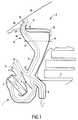
- the drawingsshow a heating, ventilation and / or air conditioning of the passenger compartment of a motor vehicle, which comprises in a housing 1, arranged in the middle area of the cockpit 2 of the vehicle and at the front of a central console 3, means 4 for heating part air A supplied by a fan unit not shown on the drawings.
- Air Aenters box 1 through an inlet 5, then is separated by a temperature adjustment flap 6, in a first upper flow, and in a second lower flow which passes through a heating branch in which a heat exchanger is installed 4.
- the two flowsare then join in a mixing zone 7, from which the treated air feeds a lower duct 8, intended to heat the lower zones of the passenger compartment, and in particular the feet of the front passengers, and a duct upper 9, substantially vertical, disposed behind the console 3.
- the upper duct 9is intended to supply, with defrosting air, a defrost branch 10 disposed in the upper facade 11 of the dashboard 12, and, in ventilation air, air vents, also arranged in the upper facade 11, of the dashboard 12.
- the upper duct 9opens into an upper face 13, of overall rectangular shape, of the housing 1. This upper face 13 preferably extends in a substantially horizontal plane, below of the upper front 11 of the dashboard 12 and at the front of the center console 3.
- An oblong diffusion module 14extends over the entire width of the passenger compartment H and at the rear of the foot of the windshield 15, and is disposed between the upper face 13 of the housing 1 and the upper facade 11 of the board on-board 12.
- This broadcasting module 14,which only includes thin walls delimiting the air ducts supplying the mouth of defrost 10 and the air vents, present on its lower wall 16, an opening 17 which fits on the upper face 13 of the housing 1 and which allows the introduction of the air delivered by the orifice of the upper face 13 of the housing 1 inside the diffusion module 14.
- the diffusion module 14is in the form of a box delimited by the bottom wall 16, a vertical front wall 18, a wall vertical rear 19, whose lateral ends 20a, 20b join the lateral ends of the front wall 18, and an upper wall 21, substantially horizontal disposed under the upper facade 13 of the dashboard 12.
- the front wall 18 and the rear wall 19are connected to the bottom wall 16.
- the top wall 21is also connected to the rear wall 19.
- the upper wall 21extends, towards the windshield 15, beyond of the front wall 19, by three portions of wall, with curvilinear section according to vertical planes parallel to the vertical median plane of cockpit 2, and directed upwards.
- the central wall portion 22constitutes the face rear of the defrost duct 23.
- the side wall portions 24a and 24b, arranged on either side of the central portion 22,form the rear faces of the ventilation ducts 25a and 25b. These two portions of side walls 24a and 24b extend laterally to the ends of the upper wall 21.
- the front wall 18has a height less than the height of the wall rear 19.
- the front face of the defrost duct 23is formed by a curved wall 26, connected to the upper end of the front wall 18, and the lateral edges of which are connected to the central wall portion 22 of the upper wall 21.
- the mouth 10 of the defrost duct 23is directed towards the windscreen 15.
- the front faces of the ventilation ducts 25a and 25bare formed by walls with a curvilinear section 27a and 27b, substantially parallel to the side wall portions 24a and 24b of the upper wall 21. These walls 27a and 27b are connected at the end upper of the front wall 18, and laterally connected to the portions side walls 24a and 24b, in order to form the downstream portions of the conduits 25a and 25b.
- the front and rear walls of the ventilation ductshave convex surfaces seen from the front of the cockpit 2, substantially in the shape of a half-cylinder, and they are connected by a plurality of vertical partitions 28, intended to channel the air of ventilation in vertical planes substantially parallel to the median plane of the cockpit 2.
- the ventilation openings 29a and 29bare arranged above the upper front 13 of the dashboard 12 and are directed towards the interior of the passenger compartment .
- the diffusing surface of these air vents 29a and 29bis at least equal to 2.5 dm 2 , in order to allow gentle diffusion of the aeration air. With a diffusing surface of this value, the aeration air exits the air vents 29a and 29b at low speed, and there is no turbulence in the passenger compartment.
- the front wall 18 of the diffusion module 14has possibly indentations not shown on the drawings intended to house cockpit indicators.
- the dashboard 12is preferably made in the form of a cap which covers the module broadcast 14.
- the portions of side walls 24a and 24bare shaped so as to spare, near their upper end, a housing 30 for a shutter adjustment 31 of the opening of the air vents 29a and 29b.
- the shutter of adjustment 31is controlled from the operator's station and allows the ventilation air outlet speeds, so as to obtain a mode of forced diffusion in a converging position of the flap 31 and a mode of soft diffusion in a divergent position of the flap 31.
- the diffusion module 14is obtained by assembling two thin-walled parts 32 and 33 made by molding a material plastic according to a known process, for example by injection.
- the plan of joint of these two partspasses through the bottom wall 16, the conduit defrost 23 and the air ducts 25a and 25b, as is shown in Figures 8 and 9.
- Distribution flaps 34are mounted on the diffusion module 14 during its assembly. These flaps 34 make it possible to distribute the air received by the diffusion module 14 between the defrost duct 23 and the air ducts 25a, 25b.
- the distribution module 14consisting of two parts 32 and 33 and equipped with flaps 31 and 34, can be fitted and tested before fitting on the cockpit.
- the ventilation ducts 25a and 25bare arranged laterally on each side of the defrost duct 25 which is located in the middle area of the cockpit.
- the broadcast module 14may have a single ventilation duct 25 which extends laterally over the entire width of the dashboard 12, behind the defrost duct 23.
- the upper wall 21 of the diffusion modulecomprises forward an edge 35 turned upwards, and the front wall 18 is extended forward and upward by a curvilinear wall 36 which forms the front face of the defrost duct 23.
- An intermediate wall 37is disposed between the edge 35 and the wall 36 to separate the conduit from defrost 23 and the ventilation duct 25.
- a distribution flap 38is then rotatably mounted on the lower end 39 of the wall intermediate 37.
- the intermediate wall 37is connected to the curvilinear wall 36 and at the edge 35 by a plurality of vertical partitions intended to channel the defrost air and the ventilation air.
- the air vents 29a and 29bare equipped so known by fins for adjusting the orientation of the air flow controlled by thumbwheels accessible respectively by the driver and front passenger.
- each conduit 25a, 25bis equipped with a means for selecting the ventilation air outlet zones.
- drum flap 50With this drum flap 50, convergent-divergent flaps can be associated 31a, 31b which make it possible to modify the speed of exit of the air in zones Z1, Z2, Z3.
- Figures 16a, 16b and 16cshow three settings of the flaps 31a and 31 b which make it possible to diffuse air respectively at low speed, at medium speed and high speed.
- the positioning of the drum flap 50 and the convergent-divergent flaps 31a, 31bcan be adjusted by manual actuation of knobs located in the handy envelope of the driver or passenger.
Landscapes
- Physics & Mathematics (AREA)
- Thermal Sciences (AREA)
- Engineering & Computer Science (AREA)
- Mechanical Engineering (AREA)
- Air-Conditioning For Vehicles (AREA)
- Instrument Panels (AREA)
Abstract
Description
Translated fromFrenchL'invention concerne un dispositif de chauffage, ventilation et/ouclimatisation de l'habitacle d'un véhicule automobile, du type comportantdes moyens de traitement d'air logeant, au moins en partie, dans unboítier muni de sorties d'air, la sortie de dégivrage et les sorties d'aérationdébouchant dans une face supérieure de forme déterminée du boítier etétant susceptibles d'alimenter en air traité au moins une bouche dedégivrage et des bouches d'aération prévues dans une façade d'uneplanche de bord par des conduits reliant lesdites sorties auxditesbouches, ladite planche de bord comportant une façade supérieure et unefaçade frontale.The invention relates to a heating, ventilation and / orair conditioning of the passenger compartment of a motor vehicle, of the type comprisingair treatment means accommodating, at least in part, in abox fitted with air outlets, defrost outlet and ventilation outletsopening into an upper face of determined shape of the housing andbeing capable of supplying treated air to at least one mouth ofdefrosting and air vents provided in a facade of adashboard by conduits connecting said outlets to saidmouths, said dashboard comprising an upper front and afront facade.
Aujourd'hui, l'acheminement de l'air de l'appareil de climatisationvers les bouches de dégivrage et d'aération se fait par le montage bout àbout de plusieurs pièces dont l'assemblage est effectué lors du montagedu poste de conduite. En outre, les bouches d'aération sonthabituellement déposées sur la façade frontale de la planche de borddans l'enveloppe de portée de main du conducteur ou du passager avantet comportent notamment une bouche d'aération centrale située au-dessusde la console centrale, et deux bouches latérales d'aération. Cesbouches d'aération, ayant des surfaces diffusantes limitées, délivrent unair d'aération à grande vitesse. En outre, la disposition de la bouched'aération centrale au-dessus de la console centrale limite le volume decette dernière.Today, the air flow from the air conditioning unitto the defrost and ventilation openings is by end-to-end mountingend of several pieces which are assembled during assemblyfrom the driving position. In addition, the air vents areusually placed on the front panel of the dashboardin the handy envelope of the driver or front passengerand include in particular a central air vent located abovecenter console, and two side air vents. Theseair vents, having limited diffusing surfaces, deliver ahigh speed ventilation air. In addition, the arrangement of the mouthcentral ventilation above the center console limits the volume ofthe latter.
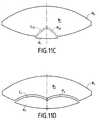
La norme internationale ISO 3958 du 15/02/1996 définit des zonesde portée de mains pour le conducteur d'un véhicule automobile. Ceszones sont définies comme étant incluses à l'intérieur de l'enveloppeextérieure de deux sphères définies géométriquement par rapport ausiège du conducteur. Chaque sphère correspond au débattement d'unemain du conducteur. Les zones de portée de mains du passager peuventêtre déduites par symétrie par rapport au plan de symétrie de l'habitacle.The international standard ISO 3958 of 02/15/1996 defines zoneshandy for the driver of a motor vehicle. Thesezones are defined as being included inside the envelopeexterior of two spheres defined geometrically with respect todriver's seat. Each sphere corresponds to the travel of adriver's hand. Passenger hand range areas canbe deduced by symmetry with respect to the plane of symmetry of the passenger compartment.
Sur la figure 10 on a représenté par les références :
Ces différentes enveloppes sphériques coupent l'enveloppeextérieure Pb de la planche de bord selon des lignes curvilignes quipartagent l'enveloppe extérieure Pb de la planche de bord en différenteszones, accessibles ou non accessibles par les doigts d'une main duconducteur ou du passager suite à une préhension avec trois doigts ou dubout des doigts. Ces lignes courbes et les zones correspondantes sontmontrées sur les figures 11a à 11 g.These different spherical envelopes cut the envelopeouter Pb of the dashboard along curvilinear lines whichshare the outer casing Pb of the dashboard in differentareas, accessible or not accessible by the fingers of one hand of thedriver or passenger following gripping with three fingers ortip of the fingers. These curved lines and the corresponding areas areshown in Figures 11a to 11g.
La zone A1 est la partie de la planche de bord qui se trouve dansl'intersection des enveloppes Cd et Pg.Zone A1 is the part of the dashboard that is inthe intersection of the Cd and Pg envelopes.
La zone B1 est complémentaire de la zone A1 dans l'enveloppe Pbde la planche de bord.Zone B1 is complementary to zone A1 in the envelope Pbof the dashboard.
La zone A2 est la partie de la planche de bord qui se trouve dansl'intersection des enveloppes Cdb et Pgb.Zone A2 is the part of the dashboard that is inthe intersection of the Cdb and Pgb envelopes.
La zone B2 est complémentaire de la zone A2 dans l'enveloppe Pbde la planche de bord.Zone B2 is complementary to zone A2 in the envelope Pbof the dashboard.
La zone A3 est la partie de la planche de bord qui se trouve dans laréunion des enveloppes Cd et Pg.Zone A3 is the part of the dashboard that is in themeeting of Cd and Pg envelopes.
La zone B3 est complémentaire de la zone A3 dans l'enveloppe Pbde la planche de bord.Zone B3 is complementary to zone A3 in the envelope Pbof the dashboard.
La zone A4 est la partie de la planche de bord qui se trouve dans laréunion des enveloppes Cd, Cg, Pd et Pg.The A4 area is the part of the dashboard that is in themeeting of Cd, Cg, Pd and Pg envelopes.
La zone B4 est complémentaire de la zone A4 dans l'enveloppe Pbde la planche de bord.Zone B4 is complementary to zone A4 in the envelope Pbof the dashboard.
La zone A5 est la partie de la planche de bord qui se trouve dans laréunion des enveloppes Cdb et Pgb.Zone A5 is the part of the dashboard that is in themeeting of Cdb and Pgb envelopes.
La zone B5 est complémentaire de la zone A5 dans l'enveloppe Pbde la planche de bord.Zone B5 is complementary to zone A5 in the envelope Pbof the dashboard.
La zone A6 est la partie de la planche de bord qui se trouve dans laréunion des enveloppes Cdb, Cgb, Pdb et Pgb.Zone A6 is the part of the dashboard that is in themeeting of Cdb, Cgb, Pdb and Pgb envelopes.
La zone B6 est complémentaire de la zone A6 dans l'enveloppe Pbde la planche de bord.Zone B6 is complementary to zone A6 in the envelope Pbof the dashboard.
Dans les définitions précédentes, le véhicule est supposé avoir unposte de conduite à gauche. Dans le cas d'un véhicule avec un poste deconduite à droite, il suffit d'inverser les mots conducteur et passager dansles définitions.In the previous definitions, the vehicle is assumed to have adriving position on the left. In the case of a vehicle with aright-hand drive, just reverse the words driver and passenger inthe definitions.
Un premier but de l'invention est de proposer une nouvellearchitecture des moyens de délivrance de l'air de dégivrage et de l'aird'aération qui permette d'augmenter la place disponible au-dessus de laconsole dans la zone d'instrumentation centrale du poste de conduite.A first object of the invention is to propose a newarchitecture of the means for delivering defrost air and airventilation which increases the space available above theconsole in the central instrumentation area of the driving position.
Un deuxième but de l'invention est de proposer une nouvellearchitecture des moyens de délivrance de l'air de dégivrage et de l'aird'aération qui permette de simplifier le montage du cockpit grâcenotamment à une diminution du nombre de pièces.A second object of the invention is to propose a newarchitecture of the means for delivering defrost air and airventilation which simplifies cockpit assembly thanks toincluding a decrease in the number of parts.
Un troisième but de l'invention est de proposer une nouvellearchitecture des moyens de délivrance de l'air d'aération qui permette, auchoix des occupants du véhicule, un mode de diffusion douce, ou unmode de diffusion forcée.A third object of the invention is to propose a newarchitecture of the means of supplying the aeration air which allows, at thechoice of vehicle occupants, a soft broadcast mode, or aforced broadcast mode.
L'invention atteint les deux premiers buts par le fait que les conduitsde dégivrage et d'aération sont ménagés dans un module de diffusionoblong qui s'étend transversalement au-dessus de la face supérieure duboítier et sous la façade supérieure de la planche de bord, ce modulecomportant dans sa face inférieure une ouverture adaptée à la forme dela face supérieure du boítier, et sur son bord supérieur avant les portionsaval du conduit de dégivrage et des conduits d'aération, les portions avaldes conduits d'aération s'étendant transversalement de part et d'autre duconduit de dégivrage et se terminant par des bouches d'aération situéesau-dessus de la zone B4 de l'enveloppe Pb de la planche de bord situéeen dehors de l'intersection A4 des enveloppes extérieures Cg, Cd, Pg, Pbde débattement des mains droite et gauche du conducteur et du passager, correspondant à une préhension avec trois doigts, et dirigéesvers l'intérieur de l'habitacle.The invention achieves the first two objects by the fact that the conduitsdefrost and aeration are provided in a diffusion moduleoblong which extends transversely above the upper face of thehousing and under the upper facade of the dashboard, this modulecomprising in its lower face an opening adapted to the shape ofthe upper face of the case, and on its upper edge before the portionsdownstream of the defrost duct and the ventilation ducts, the downstream portionsventilation ducts extending transversely on either side of thedefrost duct and ending with air vents locatedabove zone B4 of the envelope Pb of the dashboard locatedoutside the intersection A4 of the outer envelopes Cg, Cd, Pg, Pbof the right and left hands of the driver and thepassenger, corresponding to a grip with three fingers, and directedtowards the interior of the passenger compartment.
Avantageusement, le module de diffusion est obtenu parassemblage de deux pièces à parois minces. Les portions aval desconduits d'aération sont délimitées par deux parois parallèles à sectioncurviligne selon des plans verticaux parallèles au plan médian longitudinalde l'habitacle. Ces deux parois présentent des surfaces convexes du côtéavant du module de diffusion, et sont reliées par une pluralité de cloisonsverticales.Advantageously, the diffusion module is obtained byassembly of two thin-walled parts. The downstream portions ofventilation ducts are delimited by two parallel section wallscurvilinear in vertical planes parallel to the longitudinal median planeof the passenger compartment. These two walls have convex surfaces on the sidefront of the diffusion module, and are connected by a plurality of partitionsvertical.
Pour atteindre le troisième but de l'invention, les bouches d'aérationsont équipées d'un système convergent divergent réglable qui permet defaire varier les vitesses de sortie de l'air de manière à obtenir un mode dediffusion douce ou un mode de diffusion forcée. Dans le mode dediffusion douce, la surface diffusante totale des bouches d'aération est aumoins égale à 2,5 dm2.To achieve the third object of the invention, the air vents are equipped with an adjustable divergent converging system which makes it possible to vary the air outlet speeds so as to obtain a gentle diffusion mode or a forced release. In the soft diffusion mode, the total diffusing surface of the air vents is at least equal to 2.5 dm2 .
Le module de diffusion comporte avantageusement des volets dedistribution pour répartir l'air entré dans ledit module entre les conduit dedégivrage et les conduits d'aération.The dissemination module advantageously includesdistribution to distribute the air entered in said module between thedefrost and ventilation ducts.
D'autres avantages et caractéristiques de l'invention ressortiront àla lecture de la description suivante faite à titre d'exemple et en référenceaux dessins annexés dans lesquels :
Les figures 10 et 11a à 11g ont été commentés en introduction etne nécessitent pas d'explications complémentaires.Figures 10 and 11a to 11g have been commented on in the introduction anddo not require further explanation.
Les dessins montrent un dispositif de chauffage, ventilation et/ouclimatisation de l'habitacle d'un véhicule automobile, qui comporte dansun boítier 1, disposé dans la zone médiane du cockpit 2 du véhicule et àl'avant d'une console centrale 3, des moyens 4 pour réchauffer une partied'un air A délivré par un groupe motoventilateur non représenté sur lesdessins. L'air A entre dans le boítier 1 par une entrée 5, puis est séparépar un volet de réglage de température 6, en un premier flux supérieur, eten un deuxième flux inférieur qui transite par une branche de réchauffagedans laquelle est installé un échangeur de chaleur 4. Les deux flux serejoignent ensuite dans une zone de mixage 7, d'ou l'air traité alimente unconduit inférieur 8, destiné à réchauffer les zones inférieures del'habitacle, et notamment les pieds des passagers avant, et un conduitsupérieur 9, sensiblement vertical, disposé derrière la console 3. Le conduit supérieur 9 est destiné à alimenter, en air de dégivrage, unebranche de dégivrage 10 disposée dans la façade supérieure 11 de laplanche de bord 12, et, en air d'aération, des bouches d'aération,également disposées dans la façade supérieure 11, de la planche de bord12. Le conduit supérieur 9 débouche dans une face supérieure 13, deforme globalement rectangulaire, du boítier 1. Cette face supérieure 13s'étend de préférence dans un plan sensiblement horizontal, en dessousde la façade supérieure 11 de la planche de bord 12 et à l'avant de laconsole centrale 3.The drawings show a heating, ventilation and / orair conditioning of the passenger compartment of a motor vehicle, which comprises ina
Un module de diffusion 14 oblong, s'étend sur toute la largeur del'habitacle H et à l'arrière du pied du pare-brise 15, et est disposé entre laface supérieure 13 du boítier 1 et la façade supérieure 11 de la planchede bord 12. Ce module de diffusion 14, qui comporte uniquement desparois minces délimitant les conduits d'air alimentant la bouche dedégivrage 10 et les bouches d'aération, présente, sur sa paroi inférieure16, une ouverture 17 qui s'adapte sur la face supérieure 13 du boítier 1 etqui permet l'introduction de l'air délivré par l'orifice de la face supérieure13 du boítier 1 à l'intérieur du module de diffusion 14.An
Le module de diffusion 14 se présente sous la forme d'une boítedélimitée par la paroi inférieure 16, une paroi avant 18 verticale, une paroiarrière verticale 19, dont les extrémités latérales 20a, 20b rejoignent lesextrémités latérales de la paroi avant 18, et une paroi supérieure 21,sensiblement horizontale disposée sous la façade supérieure 13 de laplanche de bord 12. La paroi avant 18 et la paroi arrière 19 sontraccordées à la paroi inférieure 16. La paroi supérieure 21 est égalementraccordée à la paroi arrière 19.The
La paroi supérieure 21 se prolonge, vers le pare brise 15, au-delàde la paroi avant 19, par trois portions de paroi, à section curviligne selondes plans verticaux parallèles au plan médian vertical du cockpit 2, etdirigées vers le haut. La portion de paroi centrale 22 constitue la facearrière du conduit de dégivrage 23. Les portions de paroi latérales 24a et24b, disposées de part et d'autre de la portion centrale 22, forment lesfaces arrière des conduits d'aération 25a et 25b. Ces deux portions deparoi latérales 24a et 24b s'étendent latéralement jusqu'aux extrémités dela paroi supérieure 21.The
La paroi avant 18 a une hauteur inférieure à la hauteur de la paroiarrière 19. La face avant du conduit de dégivrage 23 est formé par uneparoi curviligne 26, raccordée à l'extrémité supérieure de la paroi avant18, et dont les bords latéraux sont raccordés à la portion de paroi centrale22 de la paroi supérieure 21. La bouche 10 du conduit de dégivrage 23est dirigée vers le pare brise 15. Les faces avant des conduits d'aération25a et 25b sont formées par des parois à section curviligne 27a et 27b,sensiblement parallèles aux portions de paroi latérales 24a et 24b de laparoi supérieure 21. Ces parois 27a et 27b sont raccordées à l'extrémitésupérieure de la paroi avant 18, et raccordées latéralement aux portionsde paroi latérales 24a et 24b, afin de former les portions aval des conduitsd'aération 25a et 25b.The
Les parois avant et arrière des conduits d'aération présentent dessurfaces convexes vues de l'avant du cockpit 2, sensiblement en forme dedemi-cylindre, et elles sont reliées par une pluralité de cloisons verticales28, destinées à canaliser l'air d'aération dans des plans verticauxsensiblement parallèles au plan médian du cockpit 2. Les bouchesd'aération 29a et 29b sont disposées au-dessus de la façade supérieure13 de la planche de bord 12 et sont dirigées vers l'intérieur de l'habitacle.La surface diffusante de ces bouches d'aération 29a et 29b est au moinségale à 2,5 dm2, afin de permettre une diffusion douce de l'air d'aération.Avec une surface diffusante de cette valeur, l'air d'aération sort desbouches d'aération 29a et 29b à faible vitesse, et il n'y a pas deturbulence dans l'habitacle.The front and rear walls of the ventilation ducts have convex surfaces seen from the front of the
La paroi avant 18 du module de diffusion 14 présenteéventuellement des renfoncements non montrés sur les dessins destinésà loger des indicateurs du poste de conduite. La planche de bord 12 estde préférence réalisée sous la forme d'une coiffe qui recouvre le modulede diffusion 14.The
Ainsi que cela est montré sur les figures 5 et 6, les portions deparoi latérales 24a et 24b sont mises en forme de manière à ménager,près de leur extrémité supérieure, un logement 30 pour un volet deréglage 31 de l'ouverture des bouches d'aération 29a et 29b. Le volet deréglage 31 est commandé du poste de conduite et permet de régler lesvitesses de sortie de l'air d'aération, de manière à obtenir un mode de diffusion forcée dans une position convergente du volet 31 et un mode dediffusion douce dans une position divergente du volet 31.As shown in Figures 5 and 6, the portions of
Le module de diffusion 14 est obtenu par assemblage de deuxpièces à paroi mince, 32 et 33, réalisées par moulage d'un matériauplastique selon un procédé connu, par injection par exemple. Le plan dejoint de ces deux pièces passe par la paroi inférieure 16, le conduit dedégivrage 23 et les conduits d'aération 25a et 25b, ainsi que cela estmontré sur les figures 8 et 9.The
Des volets de distribution 34 sont montés sur le module de diffusion14 lors de son assemblage. Ces volets 34 permettent de distribuer l'airreçu par le module de diffusion 14 entre le conduit de dégivrage 23 et lesconduits d'aération 25a, 25b.Distribution flaps 34 are mounted on the
Le module de distribution 14, constitué des deux pièces 32 et 33 etéquipé des volets 31 et 34, peut être monté et testé avant son montagesur le cockpit.The
Dans la description faite ci-dessus, les conduits d'aération 25a et25b sont disposés latéralement de chaque côté du conduit de dégivrage25 qui, lui, est situé dans la zone médiane du cockpit.In the description given above, the
Ainsi que cela est montré sur la figure 13, le module de diffusion 14peut comporter un seul conduit d'aération 25 qui s'étend latéralement surtoute la largeur de la planche de bord 12, derrière le conduit de dégivrage23. Dans ce cas, la paroi supérieure 21 du module de diffusion comportevers l'avant un bord 35 retourné vers le haut, et la paroi avant 18 estprolongée vers l'avant et vers le haut par une paroi curviligne 36 qui formela face avant du conduit de dégivrage 23. Une paroi intermédiaire 37 estdisposée entre le bord 35 et la paroi 36 pour séparer le conduit dedégivrage 23 et le conduit d'aération 25. Un volet de distribution 38 estalors monté à rotation sur l'extrémité inférieure 39 de la paroiintermédiaire 37. La paroi intermédiaire 37 est reliée à la paroi curviligne36 et au bord 35 par une pluralité de cloisons verticales destinées àcanaliser l'air de dégivrage et l'air d'aération.As shown in Figure 13, the
Les bouches d'aération 29a et 29b sont équipées de manièreconnue par des ailettes de réglage de l'orientation du flux d'aircommandées par des molettes accessibles respectivement par leconducteur et le passager avant.The air vents 29a and 29b are equipped soknown by fins for adjusting the orientation of the air flowcontrolled by thumbwheels accessible respectively by thedriver and front passenger.
Selon une autre caractéristique de l'invention, chaque conduitd'aération 25a, 25b est équipé d'un moyen permettant de sélectionner leszones de sortie du flux d'air d'aération.According to another characteristic of the invention, each
Il peut s'agir, par exemple, ainsi que cela est montré sur les figures14 et 15a à 15d, d'un volet tambour 50, qui comporte des canauxinternes, décalés angulairement autour de l'axe de rotation du volettambour 50, afin d'alimenter sélectivement des zones Z1, Z2, Z3 de labouche d'aération correspondante 29 a ou 29b. Le volet tambour 50 peutcomporter par exemple trois canaux internes 51a, 51b, 51cc, les canauxlatéraux 51a et 51c se déduisent l'un de l'autre par translation le long del'axe de rotation. Le volet tambour 50 peut prendre notamment quatrepositions telles que définies ci-après :
- une position A, montrée sur la figure 15a, dans laquelle la zone centraleZ2 est alimentée en air, et les zones latérales Z1 et Z3 de la bouched'aération correspondante sont fermées ;
- une position B, montrée sur la figure 15b, dans laquelle les trois zonesZ1, Z2, Z3 sont alimentées en air ;
- une position C, montrée sur la figure 15c, dans laquelle seules les zoneslatérales Z1, Z3 de la bouche d'aération correspondante sont alimentéesen air ;
- une position D montrée sur la figure 15d, dans laquelle la bouched'aération correspondante est fermée.
- a position A, shown in FIG. 15a, in which the central zone Z2 is supplied with air, and the lateral zones Z1 and Z3 of the corresponding air outlet are closed;
- a position B, shown in FIG. 15b, in which the three zones Z1, Z2, Z3 are supplied with air;
- a position C, shown in FIG. 15c, in which only the lateral zones Z1, Z3 of the corresponding air outlet are supplied with air;
- a position D shown in Figure 15d, in which the corresponding air vent is closed.
A ce volet tambour 50 on peut associer des volets convergent-divergent31a, 31b qui permettent de modifier la vitesse de sortie de l'airdans les zones Z1, Z2, Z3.With this
Les figures 16a, 16b et 16c montrent trois réglages des volets 31aet 31 b qui permettent de diffuser de l'air respectivement à petite vitesse, àvitesse moyenne et à grande vitesse.Figures 16a, 16b and 16c show three settings of the
Le positionnement du volet tambour 50 et des volets convergent-divergent31a, 31b peut être réglé par actionnement manuel de molettessituées dans l'enveloppe de portée de main du conducteur ou dupassager.The positioning of the
Claims (11)
Translated fromFrenchcaractérisé par le fait que lesdits conduits (23, 25a, 25b) sont ménagésdans un module de diffusion (14) oblong qui s'étend transversalement au-dessusde la face supérieure (13) du boítier (1) et sous la façadesupérieure (11) de la planche de bord (12), ce module (14) comportantdans sa face inférieure (16) une ouverture (17) adaptée à la forme de laface supérieure (13) du boítier (1), et sur son bord supérieur avant lesportions aval du conduit de dégivrage (23) et des conduits d'aération (25a,25b), les portions aval des conduits d'aération (25a, 25b) s'étendanttransversalement de part et d'autre du conduit de dégivrage (23) et seterminant par des bouches d'aération (29a, 29b) situées dans la zone (B4)de l'enveloppe (Pb) de la planche de bord (12) située en dehors del'intersection (A4) des enveloppes extérieures (Cg, Cd, Pg, Pd) dudébattement des mains droite et gauche du conducteur et du passager,correspondant à une préhension avec trois doigts, et dirigées versl'intérieur de l'habitacle.Device for heating, ventilating and / or air conditioning the passenger compartment of a motor vehicle, of the type comprising means (4) for air treatment accommodating, at least in part, in a housing (1) provided with outputs air, the defrost outlet and the ventilation outlets opening into an upper face (13) of determined shape of the housing (1) and being capable of supplying treated air to at least one defrost mouth (10) and air outlets ventilation (29a, 29b) provided in a facade of a dashboard (12) by conduits (23, 25a, 25b) connecting said outlets to said outlets, said dashboard comprising an upper facade (11) and a facade frontal,
characterized in that said conduits (23, 25a, 25b) are formed in an oblong diffusion module (14) which extends transversely above the upper face (13) of the housing (1) and under the upper facade (11) of the dashboard (12), this module (14) comprising in its lower face (16) an opening (17) adapted to the shape of the upper face (13) of the housing (1), and on its upper edge before the downstream portions of the defrost duct (23) and of the ventilation ducts (25a, 25b), the downstream portions of the ventilation ducts (25a, 25b) extending transversely on either side of the duct defrost (23) and ending with air vents (29a, 29b) located in the area (B4) of the casing (Pb) of the dashboard (12) located outside the intersection (A4 ) outer envelopes (Cg, Cd, Pg, Pd) of the movement of the right and left hands of the driver and passenger, corresponding to a grip with three fingers, e t directed towards the interior of the passenger compartment.
Applications Claiming Priority (2)
| Application Number | Priority Date | Filing Date | Title |
|---|---|---|---|
| FR9915653 | 1999-12-13 | ||
| FR9915653AFR2802150B1 (en) | 1999-12-13 | 1999-12-13 | AIR DIFFUSION IN AN AUTOMOBILE INTERIOR |
Publications (2)
| Publication Number | Publication Date |
|---|---|
| EP1108574A1true EP1108574A1 (en) | 2001-06-20 |
| EP1108574B1 EP1108574B1 (en) | 2007-04-25 |
Family
ID=9553155
Family Applications (1)
| Application Number | Title | Priority Date | Filing Date |
|---|---|---|---|
| EP00126470AExpired - LifetimeEP1108574B1 (en) | 1999-12-13 | 2000-12-07 | Distribution of air in the passenger compartment of a vehicle |
Country Status (6)
| Country | Link |
|---|---|
| US (1) | US6450876B2 (en) |
| EP (1) | EP1108574B1 (en) |
| JP (1) | JP2001199235A (en) |
| DE (1) | DE60034533T2 (en) |
| ES (1) | ES2285988T3 (en) |
| FR (1) | FR2802150B1 (en) |
Cited By (1)
| Publication number | Priority date | Publication date | Assignee | Title |
|---|---|---|---|---|
| EP1270288A3 (en)* | 2001-06-26 | 2004-01-02 | J. Eberspächer GmbH & Co. | Heating apparatus for a compartment to be heated, in particular a passenger compartment of a vehicle |
Families Citing this family (17)
| Publication number | Priority date | Publication date | Assignee | Title |
|---|---|---|---|---|
| FR2814987B1 (en)* | 2000-10-11 | 2003-04-18 | Valeo Climatisation | AIR DIFFUSION PANEL FOR MOTOR VEHICLE |
| JP3885711B2 (en)* | 2002-08-09 | 2007-02-28 | 株式会社デンソー | Air conditioning system |
| US6752712B1 (en) | 2003-02-10 | 2004-06-22 | The Boeing, Company | Slotted air distribution nozzle restrictor assembly |
| JP4475012B2 (en)* | 2004-05-31 | 2010-06-09 | 日本プラスト株式会社 | Air outlet structure for vehicles |
| FR2876958A1 (en)* | 2004-10-21 | 2006-04-28 | Renault Sas | DEVICE FOR AIR CONDITIONING A VEHICLE COMPRISING A DEFROST CHANNEL NETWORK |
| KR100683220B1 (en)* | 2005-07-05 | 2007-02-15 | 현대모비스 주식회사 | Flow structure of car defrost duct |
| US20070243812A1 (en)* | 2006-03-27 | 2007-10-18 | Behr America, Inc. | Device for ventilating a vehicle |
| PL3379152T3 (en)* | 2006-04-18 | 2021-10-11 | Oy Halton Group Ltd. | Cooking appliance and method of conveying heat energy from a cooking exhaust hood |
| FR2909935B1 (en)* | 2006-12-19 | 2015-04-24 | Renault Sas | AIR CONDITIONING DEVICE FOR A VEHICLE COMPRISING A DEFROST PIPING NETWORK |
| DE102007019539B4 (en)* | 2007-04-25 | 2012-12-13 | Airbus Operations Gmbh | Air supply device for the air conditioning of passenger compartments in airplanes |
| US20100087134A1 (en)* | 2008-10-07 | 2010-04-08 | Gm Global Technology Operations, Inc. | Vehicle hvac system |
| DE102008052794B4 (en)* | 2008-10-22 | 2014-11-20 | Airbus Operations Gmbh | Air guide element with a disturbance control element |
| US10315490B2 (en)* | 2014-07-10 | 2019-06-11 | Ford Global Technologies, Llc | Noise-attenuating snorkel duct for air-handling system recirculation vent |
| JP6417188B2 (en)* | 2014-10-31 | 2018-10-31 | ダイキョーニシカワ株式会社 | Vehicle defroster structure |
| JP2017013704A (en)* | 2015-07-03 | 2017-01-19 | 株式会社ヴァレオジャパン | Air conditioner for vehicle and vehicle mounted with air conditioner for vehicle |
| US20170313281A1 (en)* | 2016-04-28 | 2017-11-02 | GM Global Technology Operations LLC | Defrost duct with acoustic material inserts |
| JP7372093B2 (en)* | 2019-09-18 | 2023-10-31 | 三菱重工サーマルシステムズ株式会社 | Vehicle air blowing device |
Citations (3)
| Publication number | Priority date | Publication date | Assignee | Title |
|---|---|---|---|---|
| US5113748A (en)* | 1990-08-09 | 1992-05-19 | Nissan Motor Co., Ltd. | Defroster construction for automotive air conditioner |
| GB2302404A (en)* | 1995-06-15 | 1997-01-15 | Nihon Plast Co Ltd | Air conditioning duct structure for an automobile |
| FR2756801A1 (en)* | 1996-12-10 | 1998-06-12 | Reydel Sa | DASHBOARD FOR A VEHICLE, PARTICULARLY FOR MOTOR VEHICLES |
Family Cites Families (5)
| Publication number | Priority date | Publication date | Assignee | Title |
|---|---|---|---|---|
| GB9423776D0 (en)* | 1994-11-25 | 1995-01-11 | Acg Deutschland Gmbh | Dashboard assembly |
| DE19508983C1 (en)* | 1995-03-13 | 1996-02-15 | Daimler Benz Ag | Device for diffuse ventilation of vehicle interior |
| US5673964A (en)* | 1995-08-04 | 1997-10-07 | Ford Motor Company | Integral center-mounted airhandling system with integral instrument panel air-conditioning duct and structural beam |
| US5934744A (en)* | 1997-10-01 | 1999-08-10 | General Motors Corporation | Cross car structural beam |
| JPH11165524A (en)* | 1997-12-01 | 1999-06-22 | Moriroku Company Ltd | Duct device for air conditioning of automobile |
- 1999
- 1999-12-13FRFR9915653Apatent/FR2802150B1/ennot_activeExpired - Fee Related
- 2000
- 2000-12-07ESES00126470Tpatent/ES2285988T3/ennot_activeExpired - Lifetime
- 2000-12-07EPEP00126470Apatent/EP1108574B1/ennot_activeExpired - Lifetime
- 2000-12-07DEDE60034533Tpatent/DE60034533T2/ennot_activeExpired - Fee Related
- 2000-12-12USUS09/733,922patent/US6450876B2/ennot_activeExpired - Fee Related
- 2000-12-13JPJP2000379285Apatent/JP2001199235A/enactivePending
Patent Citations (3)
| Publication number | Priority date | Publication date | Assignee | Title |
|---|---|---|---|---|
| US5113748A (en)* | 1990-08-09 | 1992-05-19 | Nissan Motor Co., Ltd. | Defroster construction for automotive air conditioner |
| GB2302404A (en)* | 1995-06-15 | 1997-01-15 | Nihon Plast Co Ltd | Air conditioning duct structure for an automobile |
| FR2756801A1 (en)* | 1996-12-10 | 1998-06-12 | Reydel Sa | DASHBOARD FOR A VEHICLE, PARTICULARLY FOR MOTOR VEHICLES |
Cited By (2)
| Publication number | Priority date | Publication date | Assignee | Title |
|---|---|---|---|---|
| EP1270288A3 (en)* | 2001-06-26 | 2004-01-02 | J. Eberspächer GmbH & Co. | Heating apparatus for a compartment to be heated, in particular a passenger compartment of a vehicle |
| DE10164694B4 (en)* | 2001-06-26 | 2010-02-11 | J. Eberspächer GmbH & Co.KG | Heating device for arrangement in a room to be heated, in particular passenger compartment of a vehicle |
Also Published As
| Publication number | Publication date |
|---|---|
| FR2802150B1 (en) | 2002-03-01 |
| DE60034533T2 (en) | 2007-12-27 |
| EP1108574B1 (en) | 2007-04-25 |
| FR2802150A1 (en) | 2001-06-15 |
| JP2001199235A (en) | 2001-07-24 |
| US20010039178A1 (en) | 2001-11-08 |
| DE60034533D1 (en) | 2007-06-06 |
| US6450876B2 (en) | 2002-09-17 |
| ES2285988T3 (en) | 2007-12-01 |
Similar Documents
| Publication | Publication Date | Title |
|---|---|---|
| EP1108574B1 (en) | Distribution of air in the passenger compartment of a vehicle | |
| FR2659907A1 (en) | HEATING AND VENTILATION DEVICE WITH SEPARATE MEANS OF TEMPERATURE ADJUSTMENT IN THE PLACES BEFORE THE COCKPIT OF A MOTOR VEHICLE. | |
| FR2909935A1 (en) | AIR CONDITIONING DEVICE FOR A VEHICLE COMPRISING A DEFROST PIPING NETWORK | |
| EP1173340B1 (en) | Device for circulating an air flow in a passenger compartment with soft diffusion | |
| FR2799157A1 (en) | Climate control system, for vehicles, has central ventilating outlet in defined location to give smoother flow of air and increased space for central console | |
| EP0600778A1 (en) | Heating, ventilation and/or air conditioning device for a motor vehicle interior | |
| EP0566474B2 (en) | Heating, ventilation and/or conditioning device for a motor vehicle interior | |
| EP1254795B1 (en) | Device for diffusing air to the forward section of a motor vehicle passenger compartment | |
| EP0961698B2 (en) | Heating/air-conditioning device integrated in a motor vehicle instrument panel | |
| EP2106941B1 (en) | Heating, ventilating and / or air conditioning apparatus for motor vehicle | |
| EP2814678B1 (en) | Heating, ventilation and/or air conditioning facility for a passenger compartment of a motor vehicle | |
| EP1484206B1 (en) | A heating/air-conditioning device suitable for housing in a vehicle flat instrument panel | |
| EP3303030B1 (en) | Roof fitting for diffusing conditioned air into the rear part of the cabin of a motor vehicle | |
| WO2014041304A1 (en) | Compact heating/air-conditioning unit for motor vehicles | |
| FR2876958A1 (en) | DEVICE FOR AIR CONDITIONING A VEHICLE COMPRISING A DEFROST CHANNEL NETWORK | |
| FR2778150A1 (en) | DEVICE FOR HEATING AND / OR AIR-CONDITIONING THE INTERIOR OF A VEHICLE, WITH IMPROVED AIR MIXING | |
| FR2781428A1 (en) | HEATING-VENTILATION DEVICE FOR A MOTOR VEHICLE, WITH INDIVIDUAL CONTROL ACCORDING TO THE AREAS OF THE COCKPIT | |
| FR3136405A1 (en) | Ventilation device for a motor vehicle, ventilation assembly and corresponding motor vehicle | |
| FR3148829A1 (en) | COANDA EFFECT VENTILATOR FOR A MOTOR VEHICLE DASHBOARD | |
| EP4201719A1 (en) | Arrangement of a dashboard provided with a display screen | |
| FR2869844A1 (en) | VEHICLE DASHBOARD | |
| FR3132052A1 (en) | Front type aerator for automotive vehicle | |
| FR2891201A3 (en) | Grille for air ducts in cars has sloping bores linking its rear surface and its front surface which direct air to position in front of and above head of passenger | |
| FR3101285A1 (en) | Vehicle ventilation device | |
| FR2904262A1 (en) | SOFT DIFFUSION AERATION DEVICE |
Legal Events
| Date | Code | Title | Description |
|---|---|---|---|
| PUAI | Public reference made under article 153(3) epc to a published international application that has entered the european phase | Free format text:ORIGINAL CODE: 0009012 | |
| AK | Designated contracting states | Kind code of ref document:A1 Designated state(s):DE ES GB IT | |
| AX | Request for extension of the european patent | Free format text:AL;LT;LV;MK;RO;SI | |
| 17P | Request for examination filed | Effective date:20011212 | |
| AKX | Designation fees paid | Free format text:DE ES GB IT | |
| GRAP | Despatch of communication of intention to grant a patent | Free format text:ORIGINAL CODE: EPIDOSNIGR1 | |
| GRAS | Grant fee paid | Free format text:ORIGINAL CODE: EPIDOSNIGR3 | |
| GRAA | (expected) grant | Free format text:ORIGINAL CODE: 0009210 | |
| RAP1 | Party data changed (applicant data changed or rights of an application transferred) | Owner name:VALEO SYSTEMES THERMIQUES | |
| AK | Designated contracting states | Kind code of ref document:B1 Designated state(s):DE ES GB IT | |
| REG | Reference to a national code | Ref country code:GB Ref legal event code:FG4D Free format text:NOT ENGLISH | |
| REF | Corresponds to: | Ref document number:60034533 Country of ref document:DE Date of ref document:20070606 Kind code of ref document:P | |
| GBV | Gb: ep patent (uk) treated as always having been void in accordance with gb section 77(7)/1977 [no translation filed] | Effective date:20070425 | |
| REG | Reference to a national code | Ref country code:ES Ref legal event code:FG2A Ref document number:2285988 Country of ref document:ES Kind code of ref document:T3 | |
| PLBE | No opposition filed within time limit | Free format text:ORIGINAL CODE: 0009261 | |
| STAA | Information on the status of an ep patent application or granted ep patent | Free format text:STATUS: NO OPPOSITION FILED WITHIN TIME LIMIT | |
| 26N | No opposition filed | Effective date:20080128 | |
| PG25 | Lapsed in a contracting state [announced via postgrant information from national office to epo] | Ref country code:GB Free format text:LAPSE BECAUSE OF FAILURE TO SUBMIT A TRANSLATION OF THE DESCRIPTION OR TO PAY THE FEE WITHIN THE PRESCRIBED TIME-LIMIT Effective date:20070425 | |
| PGFP | Annual fee paid to national office [announced via postgrant information from national office to epo] | Ref country code:ES Payment date:20081222 Year of fee payment:9 | |
| PGFP | Annual fee paid to national office [announced via postgrant information from national office to epo] | Ref country code:IT Payment date:20081219 Year of fee payment:9 | |
| PGFP | Annual fee paid to national office [announced via postgrant information from national office to epo] | Ref country code:DE Payment date:20081210 Year of fee payment:9 | |
| PG25 | Lapsed in a contracting state [announced via postgrant information from national office to epo] | Ref country code:DE Free format text:LAPSE BECAUSE OF NON-PAYMENT OF DUE FEES Effective date:20100701 | |
| PG25 | Lapsed in a contracting state [announced via postgrant information from national office to epo] | Ref country code:IT Free format text:LAPSE BECAUSE OF NON-PAYMENT OF DUE FEES Effective date:20091207 | |
| REG | Reference to a national code | Ref country code:ES Ref legal event code:FD2A Effective date:20110401 | |
| PG25 | Lapsed in a contracting state [announced via postgrant information from national office to epo] | Ref country code:ES Free format text:LAPSE BECAUSE OF NON-PAYMENT OF DUE FEES Effective date:20110322 | |
| PG25 | Lapsed in a contracting state [announced via postgrant information from national office to epo] | Ref country code:ES Free format text:LAPSE BECAUSE OF NON-PAYMENT OF DUE FEES Effective date:20091208 |