EP1107052B1 - Method and apparatus for image projection, and apparatus for controlling image projection - Google Patents
Method and apparatus for image projection, and apparatus for controlling image projectionDownload PDFInfo
- Publication number
- EP1107052B1 EP1107052B1EP00935576AEP00935576AEP1107052B1EP 1107052 B1EP1107052 B1EP 1107052B1EP 00935576 AEP00935576 AEP 00935576AEP 00935576 AEP00935576 AEP 00935576AEP 1107052 B1EP1107052 B1EP 1107052B1
- Authority
- EP
- European Patent Office
- Prior art keywords
- image
- curved surface
- mask
- image projection
- projected
- Prior art date
- Legal status (The legal status is an assumption and is not a legal conclusion. Google has not performed a legal analysis and makes no representation as to the accuracy of the status listed.)
- Expired - Lifetime
Links
Images


Classifications
- H—ELECTRICITY
- H04—ELECTRIC COMMUNICATION TECHNIQUE
- H04N—PICTORIAL COMMUNICATION, e.g. TELEVISION
- H04N9/00—Details of colour television systems
- H04N9/12—Picture reproducers
- H04N9/31—Projection devices for colour picture display, e.g. using electronic spatial light modulators [ESLM]
- H04N9/3191—Testing thereof
- H04N9/3194—Testing thereof including sensor feedback
- H—ELECTRICITY
- H04—ELECTRIC COMMUNICATION TECHNIQUE
- H04N—PICTORIAL COMMUNICATION, e.g. TELEVISION
- H04N5/00—Details of television systems
- H04N5/74—Projection arrangements for image reproduction, e.g. using eidophor
Definitions
- This inventionrelates to a method and apparatus for projecting an image on a three-dimensional curved surface and an image projection control apparatus for controlling the image projection on a three-dimensional curved surface.
- the conventional image projection apparatusis designed to project an image on the stationary planar object; see e.g. JP 08201913A . Therefore, the conventional image projection device has found only limited application.
- the present inventionhas been proposed for overcoming the above-mentioned deficiency, and is aimed at providing an image projection method and apparatus for projecting an image on an object other than a stationary planar object, and an image projection control apparatus for controlling the image projection.
- the present inventionprovides an image projection apparatus according to claim 3.
- the present inventionalso provides an image projection method according to claim 8.
- the present inventionalso provides an image projection control apparatus according to claim 1.
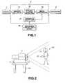
- the image projection apparatusincludes a camera 1, used as image pickup means for detecting the position and the orientation of a curved surface of an object on which an image is to be projected, a computer 3 for processing an image being projected based on image pickup signals from the camera 1, and a projector 2 for projecting the image from the computer 3 on the curved surface under consideration.
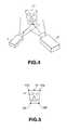
- the image projection apparatus of the present embodimentis used for a configuration shown for example in Fig.2 .
- the curved surfaceas an object for image projection, is assumed to be a mask 11 worn by a person 10.
- the mask 11is preferably white in color to display an image formed by the projector 2, it is not limitative.
- an image projection apparatusmade up of the camera 1, projector 2 and the computer 3 on a desk 101, at a pre-set distance from the person 10 under consideration.
- the camera 1images the mask 11 set on the head of the person 10 to output image signals.
- the computer 2detects the attitude or the position of the mask 11 from the image signals from the camera 1 to prepare an image of a face from the image signals of the camera 1.
- the projector 2projects an image of the face prepared by the computer 3 on the mask 11.
- the person 11is able to control the expressions of the image of the face projected on the mask by an expression control signal input device 12.
- the expression control signal input device 12can, of course, be directly connected to the computer 3.
- a keyboardfor example, may be employed.
- the camera 1, constituting the image projection apparatus of Fig.1detects an image incident from the mask 11 as a three-dimensional curved surface by a two-dimensional image frame.
- the camera 1may, for example, be a so-called CCD image pickup device, comprised of a two-dimensional array of plural charge-coupled devices (CCDs) as image pickup elements.
- CCDscharge-coupled devices
- the camera 1outputs image signals of, for example, the NTSC (National Television System Committee) system.
- the computer 3is made up of a marker follower 31 for detecting the positions of markers on the mask 11 to pursue the mask 11, an attitude and/or position prediction unit 32 for predicting the attitude and/or position such as the direction or the position of the mask 11, an image preparing unit 33 for preparing an image based on the attitude and/or the position predicted by the attitude and/or position prediction unit 32 and a parameter outputting unit 34 for outputting parameters to the image preparing unit 33 responsive to control signals sent from the expression control signal input device 12.
- a so-called personal computermay, for example, be employed.
- the marker follower 31, attitude and/or position prediction unit 32, image preparing unit 33 and the parameter outputting unit 34are realized as functional blocks of a program executed on the computer 3.
- the projector 2forms an image from the computer 1 on the mask 11 as the three-dimensional curved surface.
- a so-called video projectornot having a cathode ray tube nor an objective lens, may, for example, be employed.
- the expression control signal input device 12is fed with a control signal controlling the expression of a face projected on the mask by the user, and transmits the input signal to the computer 3.
- the expression control signal input device 12modulates the input control signal with e.g., IR rays to transmit the modulated control signal to the computer 3.
- FIG.3A specified embodiment of the above-described image projection apparatus, realized in a so-called distributed processing system comprised of plural computers interconnected over a network, is explained with reference to Fig.3 .
- the parts of the present specified embodiment corresponding to those of the image projection apparatus shown in Fig.1are depicted by the same reference numerals.
- FIG.3This distributed processing system is partially shown in Fig.3 , in which an ith computer 3i and a jth computer 3j are connected to the network 10.
- the network 10is e.g., LAN (Local Area Network) and, more specifically, may be constituted e.g., by so-called Ethernet.
- LANLocal Area Network
- EthernetEthernet
- the ith computer 3iis employed as an image projection apparatus.
- This ith computer 3iincludes a CPU 4, a ROM 5 and a RAM 6.
- a so-called stand-alone personal computermay be used.
- the ith computerused as the image projection apparatus, is connected to the network over a communication device 23, while being connected to the camera 1, projector 2, an input device 12 and a reception device 22.
- the communication device 23adjusts data transmission/reception between the ith computer 3i and the network 10.
- a network interfacing devicefor example, is used.
- Ethernetis used as the network 10
- a so-called Ethernet controlleris used as the communication device 23.
- a keyboardfor example, is used, and data is inputted by the user to the ith computer 3i.
- the reception device 22receives a signal sent from a remote controller 21 to send the received signal to the ith computer 3i.
- the reception device 22includes a photodetector for detecting a signal sent from the remote controller 21 by IR rays and demodulates the signal detected by this photodetector to send the demodulated signal to the ith computer 3i.
- This reception device 22may, for example, be a parallel interfacing device.
- an external storage device 7such as a hard disc drive
- a portable storage device 8such as a so-called CD-ROM drive.
- the external storage device 8is a large-capacity storage device and stores image data photographed e.g., by the camera 1.
- the portable storage device 8stores data in the portable medium.
- In the portable mediumthere is stored a control program necessary to utilize the ith computer 3i as an image projection apparatus.
- a control program for controlling the ith computer 3i as the image projection apparatusis read into the RAM 6.
- the CPU 4executes this control program to cause the operation of th ith computer 3i as the image projection apparatus.
- the marker follower 31, attitude and/or position prediction unit 32, image preparing unit 33 and the parameter outputting unit 34correspond to the functional blocks of the control program executed by the CPU 4.
- the expression control signal input device 12 in the image projection apparatus shown in Fig.1is realized by the remote controller 21 or by the input device 12. That is, in the ith computer 3i, the control signal for controlling the expression is remote-inputted by the remote controller 21 or inputted to the input device 12 such as a keyboard connected to the ith computer 3i.
- the processing pertinent to the image projection such as image creationis executed by the ith computer 3i to which are connected the camera 1 and the projector 2.
- this processingneed not necessarily be executed by the ith computer 3i to which are connected the camera 1 and the projector 2.
- this processingmay be executed by the jth computer 3j connected to the ith computer 3i over the network 10.
- the computer 3detects the position of the mask 11 from the image thereof photographed by the camera 1, prepares the image based on the position by the computer 3 and projects the image formed by the projector 2 on the mask 11 at this position, as shown in Fig.4 .
- the marker positionis detected, in the present embodiment, in place of using the algorithm for detecting characteristic points extremely sensitive to the continuity of the digitizing process and the noise.
- the markeran infrared LED is used.
- An IR paint or physical markersmay also be used as a marker.
- first to fifth markers 12a, 12b, 12c, 12d and 13by LEDs (light emitting diodes), are mounted on the mask 11 of Fig.4 , for detecting the mask position, as shown in Fig.5 .
- These first to fifth markers 12a, 12b, 12c, 12d and 13are mounted so as not to overlap with one another by usual bodily movements of the user 10 wearing the mask 11, such as movement of swinging his or her head.
- the marker follower 31 of the computer 3pursues the first to fifth markers 12a, 12b, 12c, 12d and 13 to detect the position of the mask 11.
- the first to fifth markers 12a, 12b, 12c, 12d and 13can readily be recognized in the photographed image by mounting an IR filter eliminating light rays other than the IR rays on the camera 11. Since the mask 11 is moving, the first to fifth markers 12a, 12b, 12c, 12d and 13 appear as a cluster (aggregated mass) of pixels in the image photographed by the camera 1 carrying the IR filter.
- the marker follower 31first detects the cluster of pixels (set of pixels) associated with the first to fifth markers 12a, 12b, 12c, 12d and 13.
- the marker follower 31detects a "source point", which proves a center point of the pixel cluster, for each pixel cluster.
- the marker follower 31detects the source points in real-time. A label is affixed to each source point.
- the marker follower 31detects the position of the mask 11 by adapting the source points, detected as described above, ultimately to a known pattern. Since the mask rotates freely, a label indicating each source point is affixed to each source point in order to discriminate the source points, changed in their positions or orientation by rotation, from one another. The pattern is selected so as not to be ambiguous to permit facilitated labelling of the respective source points, and is stored in a storage device.
- the first to fifth markers 12a, 12b, 12c, 12d and 13are attached to the right end of an upper side of the face, at the right end of the lower side of the face, opposite to the upper side, at the left end of the lower side, at the right end of the upper side and at a mid point of the upper side of the face, respectively.
- the first marker 12athe second marker 12b, the third marker 12c and the fourth marker 12d are sufficient to detect the position in the three-dimensional space of the mask 11.
- the fifth marker 13is arranged on a collinear point lying on the same straight line as that of the first and fourth markers 12a, 12d, and hence eliminates ambiguity in labelling. That is, this fifth marker 13 lies on a straight line interconnecting the first and fourth markers 12a, 12d and is disposed therebetween to facilitate its discrimination.
- the attitude and/or position prediction unit 32predicts the attitude and the position of the mask 11 based on the position of the mask 11 as detected by the marker follower 31. This attitude and/or position prediction unit 32 reduces the "shift effect" caused by movement of the mask 11.
- the shift effectis meant such an effect in which, since the image pickup by the camera 1 occurs at discrete time points, the image prepared on the basis of the image c(t) photographed at time point t is projected at time t + ⁇ t, however, the mask position at time point t differs from the mask position at time point t + ⁇ t, with the result that the image projected from the projector 2 is deviated with respect to the mask 11.
- the noise elimination processingis carried out in connection with the prediction of the attitude and/or position performing by the attitude and/or position prediction unit 32.
- a noise filteris used for this noise elimination.
- Kalman filterwhich is an optimum filter derived from the root mean square (rms) standard.
- the Kalman filteroptimally uses non-accurate data in a linear or substantially linear system having a Gaussian error to continuously update the optimum evaluation of the current state of the system.
- an extended Kalman filteris used for a non-linear system. In the present invention, the latter is used in view of the problem to be solved.
- the image preparing unit 33 of the image projection apparatusprepares an image of a face to be projected on the mask 11.
- the position of the projected imageis calculated using the homography. This will be explained substantially in detail in connection with calibration.
- the image of the mask projected on the mask 11 presenting a three-dimensional curved surfaceneeds to be prepared more meticulously than the image projected on the two-dimensional plane. It is because a surface which should be hidden in the virtual theoretical mask should not appear on the physical virtual mask. To this end, it is necessary to find the three-dimensional coordinates of the mask 11 so that the hidden surface will not be projected on the mask 11.
- the picture qualityis improved by routine techniques such as splatting or deghosting.
- the image preparing unit 33prepares an image of a face taking the feeling expression, mouth movement synchronization to the speech, expression and character into account. This improves the expression capabilities of an actor as a user wearing the mask 11.
- the image preparing unit 33varies the image of the face projected on the mask 11, time lapse or the reaction of the spectator viewing the image projected on the mask 11.
- the mouth opening/closureis synchronized in its movement with the speech enunciation by the user.
- the mouth movementis made by predicting the mouth movement based on the speech enunciation by the user. Specifically, mouth movement is predicted based on the vowel by exploiting the fact that the vowel in general is articulated with a larger mouth movement. This prediction of the mouth movement is by the neural network which has learned the relation between the vowel and the mouth movement.
- the image preparing unit 33is fed with a control signal from the expression control input device actuated by the user.
- the image preparing unit 33is responsive to parameters inputted by the parameter outputting unit 34 to vary the image of the face to be produced. For example, if the actor as a user wearing the mask 11 is performing a play, the expression of the image of the face projected on the mask 11 can be varied responsive to the performance by the input to the expression control signal input device 12. For example, the actor is able to vary the expression of a face projected on the mask 11, responsive to the dialog the actor has with the spectator.
- the parameter outputting unit 34 of the image projection apparatusreceives a control signal controlling the expression of the image of the face sent from the expression control signal input device 12 to output the received contents as parameters to the image preparing unit 33.
- the image preparing unitdemodulates the control signal sent from the expression control signal input device 12 by IR communication to output the demodulated control signal as pre-set parameters,
- the projector 2can be deemed to be a camera 1 having the opposite light propagating direction, the relative positions of the points observed from the camera 1 and the projector 2 are equivalent insofar as the camera 1 and the projector 2 are concerned.
- the relation between the camera 1 and the projector 2may be handled as a geometrical problem by homography or collinearity.
- the homography or collinearitydefines the linear relation which preserves the incidence relation and straightness of lines in the projective space and may be represented as a 3-row 3-column matrix.
- the geometrical relative positions between the camera 1 and the projector 2is negatively calibrated without directly calculating the intrinsic and extrinsic parameters in their entirety. This evades occurrence of voluminous computations or errors undesirably produced when directly computing the parameters.
- calibration of the relative positionsmeans that a known fixed pattern projected on the mask 11 needs to be brought into coincidence with the corresponding real pattern drawn on the mask 11 by a manual operation.
- the position of a screen 14 relative to the camera 1 and the projector 2is adjusted with the first to fifth markers 12a, 12b, 12c, 12d and 13, mounted on the screen 14, shown in Fig.5 , corresponding to the mask 11, as a reference pattern.
- the sequence of the calibrationis now explained with reference to Fig.7 .
- the projector 2projects first to fifth source points, making up a reference pattern, associated with the first to fifth markers 12a, 12b, 12c, 12d and 13 on the mask 11, respectively, on the screen 14.
- the projector 2is adjusted as to the position of the screen 14 corresponding to the mask 11 so that the first to fifth source points will be in register with the positions of the first to fifth markers 12a, 12b, 12c, 12d and 13 of the mask 11 as drawn on the screen 14..
- the projector 2may be moved, with the screen 14, that is the mask 11, remaining fixed, or both the projector and the screen 14, that is the mask 11, may be moved.
- This adjustmentis performed by the user by visual inspection so that the first to fifth source points will overlap with the first to fifth markers 12a, 12b, 12c, 12d and 13 on the screen 14 (mask 11). If the user has confirmed that the first to fifth source points are in register with the first to fifth markers 12a, 12b, 12c, 12d and 13 on the mask 11, he or she pushes a "calibration button" provided on the image projection apparatus to input the effect that the relative position calibration has been completed. Meanwhile, the "calibration button” may be implemented by an input key of a keyboard, if so desired.
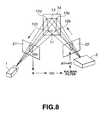
- the points c photographed by the camera 1 and the points p projected by the projector 2are given as positions of the projections in a first frame 21 and in a second frame 22, respectively.
- the points c and pare expressed as the positions in image elements of the camera 1 or the projector 2.
- the image projection apparatuscan use the geometrical relation of correspondence between the image of the mask 11 photographed by the camera 1 and the image of the mask projected by the projector 2. That is, the image projection apparatus is able to prepare an image based on the position of the screen 14 (mask 11) photographed by the camera 1 to project the so-prepared image at a position in register with the screen 14 (mask 11).
- the relative positions between the camera 1, photographing the image of the mask 11 as a three-dimensional curved surface, and the projector 2, projecting the image to the mask 11,are calibrated.
- the above-described calibrationis executed.
- the camera 1photographs an image including the first to fifth markers 12a, 12b, 12c, 12d and 13 of the screen 14 (mask 11).
- the marker follower 31 of the computer 3predicts the marker positions. That is, the marker follower 31 observes and detects the positions of the points c(t) corresponding to the first to fifth markers 12a, 12b, 12c, 12d and 13 on the screen 14 (mask 11), as shown in Fig.10 . This is carried out by detecting a center source point from a pixel cluster representing the point c(t).
- the observed values c ⁇ (t) of the points c(t), thus detected,are converted into observed values p ⁇ (t), corresponding to the projector 2, by the matrix H representing the homography as discussed above.
- the observed values p ⁇ (t) of the points p(t)are corrupted by errors. It is noted that the symbol " ⁇ " indicates that the value is the observed value.
- the points p(t) corresponding to the first to fifth markers 12a, 12b, 12c, 12d and 13 projected by the projector 2correspond to the points c(t) corresponding in turn to the first to fifth markers 12a, 12b, 12c, 12d and 13 photographed by the camera 1 at the time point t.
- the above-mentioned conversionis based on this relation of correspondence.
- step S32the noise is removed by calculations by the two-dimensional Kalman filter, based on the observed value p ⁇ (t) of the points p(t) obtained at step S31, so that the predicted value p (t + 1) at a time point t+1 advanced by one cycle is predicted based on the observed value p ⁇ (t). Specifically, the time is advanced by 1 in order to cope with the image creation at step S26 and with image projection at step S27 as will be explained subsequently. After this step S32, processing reverts to step S23.
- the attitude and/or position prediction unit 32 of the computer 3prepares the three-dimensional information from the two-dimensional information, based on the predicted value p(t+1) at time point t + 1.
- the position in the three-dimensional spacecan be found for the positions thereof in the two-dimensional plane.
- the similar processingmay be used for preparing the three-dimensional information from the two-dimensional information.
- the attitude and/or position prediction unit 32 of the computer 3predicts the attitude and position of the mask 11 based on the three-dimensional information as found at step S24.
- the attitude and/or position prediction unit 32 at step S41predicts the attitude and the position by the Kalman filter, using (T ⁇ , R ⁇ ) of the mask 11 obtained based on the three-dimensional information from step S24, as shown in Fig.11 .
- T ⁇ and R ⁇denote transform vector and rotation matrix, respectively, and represent the coordinate system indicating the attitude and/or position of the mask 11 with respect to the reference coordinate system by transform and rotation, respectively.
- step S41prediction values (T, R) indicating the attitude and/or position of the mask are obtained by calculations of the three-dimensional Kalman filter. After the processing at this step S41, processing reverts to step S25.
- the image preparing unit 33 of the computer 3prepares an image based on the positions of the points p (t+1) corresponding to the first to fifth markers 12a, 12b, 12c, 12d and 13 predicted by the attitude and/or position prediction unit 32.
- the projector 2projects the image prepared at step S26 on the screen 14.
- This modificationcauses movement of the image projection apparatus.
- the image projection apparatusis arranged within a hand-driven cart 102.
- An image projection apparatus, arranged within the hand-driven cart 102,includes a camera 1, a projector 2, a computer 3 and an expression control signal input device 12. Meanwhile, parts or components constituting the image projection apparatus are similar to those of the previous embodiment and hence are not explained specifically.
- the hand-driven cart 102is moved by a user 10 thrusting its one end.
- the camera 1 and the projector 2, arranged in the inside of the hand-driven cart 102,have the image-pickup direction and the projection direction oriented towards the head of the user 10 wearing the mask 11.
- the image projected from the projector 2is directed to the mask 11 of the user 10 so that the mask 11 is imaged by the camera 1.
- On the mask 11 of the user 10is projected an image of the face expression.
- the expression control signal input device 12fed with a control signal controlling the expression projected on the mask 11.
- the person 10, acting on the expression control signal input device 12,is able to control the expression projected on the mask 11, as he or she moves the hand-driven cart 102.
- the hand-driven cart 102is simulated to a linen cart carrying a linen, such as pillow cover or sheets, and an actress playing the part of a motel maid thrusts the cart.
- the expression of the face projected on the mask 11 worn on the head of the actoris changed with the elocution, contents of the story, and with the dialog with the spectator.
- the image projection apparatus of the above-described embodimentprojects an image of the face of the moving image on a physical mask worn by the user who is an actor.
- a pre-set areasuch as a stage
- the position and the direction of the mask 11is detected by the camera 1, while the projected image is also moved with the mask 11.
- the attitude, such as the orientation, of the mask 11is changed, the projected image is changed with the viewing point of the spectator as a reference.
- the lip of the face projected on the mask 11is automatically synchronized with the user speech in real-time.
- the useris also able to control the expression of the face.
- infra-red LEDsare used, as an example, as the markers.
- the present inventionis not limited to this configuration.
- physical markerssuch as IR paint or magnetic materials, can also be utilized as the markers.
- the position of the mask 11 symmetrical with respect to the camera 1 and the projector 2is adjusted.
- the present inventionis not limited to this configuration. For example, it is possible to control the positions of at last two or all of the camera, projector 1 and the mask 11.
- an imagecan be projected on a moving curved surface, so that, by projecting expressions of a face of a moving picture on a mask worn by an actor, there may be provided a new method for performing a story. That is, by controlling the expressions of a face projected on a mask worn by an actor to desired ones, the actor and the image projected on the mask may be adapted to each other in relation to the spectator.
Landscapes
- Engineering & Computer Science (AREA)
- Multimedia (AREA)
- Signal Processing (AREA)
- Controls And Circuits For Display Device (AREA)
- Projection Apparatus (AREA)
- Transforming Electric Information Into Light Information (AREA)
Description
- This invention relates to a method and apparatus for projecting an image on a three-dimensional curved surface and an image projection control apparatus for controlling the image projection on a three-dimensional curved surface.
- There has hitherto been furnished an image projection apparatus for projecting a still image on a fixed planar object, such as a so-called overhead projector. There has also been furnished an image projection apparatus for projecting an image of a moving picture on a fixed planar object, such as a film projection device.
- So, the conventional image projection apparatus is designed to project an image on the stationary planar object; see e.g.
JP 08201913A - One image projection apparatus designed to project an image on a moving object is shown in
EP044 76 10 A1 , - The present invention has been proposed for overcoming the above-mentioned deficiency, and is aimed at providing an image projection method and apparatus for projecting an image on an object other than a stationary planar object, and an image projection control apparatus for controlling the image projection.
- For accomplishing the above object, the present invention provides an image projection apparatus according to
claim 3. - The present invention also provides an image projection method according to
claim 8. - The present invention also provides an image projection control apparatus according to
claim 1. Fig.1 is a block diagram showing a schematic structure of an image projection apparatus.Fig.2 shows an example of the using state of the image projection apparatus.Fig.3 is a block diagram showing a specified example of the image projection apparatus.Fig.4 shows the state of image projection on a mask by the image projection apparatus.Fig.5 shows markers fitted on a mask.Fig.6 illustrates calibration of the image projection apparatus.Fig.7 shows a flowchart illustrating the operation of the image projection apparatus.Fig.8 illustrates the use of a Kalman filter in the image projection apparatus.Fig.9 is a flowchart showing a step of image projection of the image projection apparatus.Fig.10 shows a flowchart for illustrating the step of predicting a marker position.Fig.11 shows a flowchart for illustrating the step of predicting a attitude and/or a position.Fig.12 shows another embodiment of the image projection apparatus.- In the following, preferred embodiments of the image projection apparatus according to the present invention will be explained by referring to the drawings.
- The image projection apparatus according to the present invention includes a
camera 1, used as image pickup means for detecting the position and the orientation of a curved surface of an object on which an image is to be projected, acomputer 3 for processing an image being projected based on image pickup signals from thecamera 1, and aprojector 2 for projecting the image from thecomputer 3 on the curved surface under consideration. - The image projection apparatus of the present embodiment is used for a configuration shown for example in
Fig.2 . In the present embodiment:, the curved surface, as an object for image projection, is assumed to be amask 11 worn by aperson 10. Although themask 11 is preferably white in color to display an image formed by theprojector 2, it is not limitative. There is shown in the drawing an image projection apparatus, made up of thecamera 1,projector 2 and thecomputer 3 on adesk 101, at a pre-set distance from theperson 10 under consideration. - In the image projection apparatus, the
camera 1 images themask 11 set on the head of theperson 10 to output image signals. Thecomputer 2 detects the attitude or the position of themask 11 from the image signals from thecamera 1 to prepare an image of a face from the image signals of thecamera 1. Theprojector 2 projects an image of the face prepared by thecomputer 3 on themask 11. Theperson 11 is able to control the expressions of the image of the face projected on the mask by an expression controlsignal input device 12. - Although a device such as a remote controller is drawn on the expression control
signal input device 12, the expression controlsignal input device 12 can, of course, be directly connected to thecomputer 3. As this expression controlsignal input device 12, a keyboard, for example, may be employed. - The
camera 1, constituting the image projection apparatus ofFig.1 , detects an image incident from themask 11 as a three-dimensional curved surface by a two-dimensional image frame. Thecamera 1 may, for example, be a so-called CCD image pickup device, comprised of a two-dimensional array of plural charge-coupled devices (CCDs) as image pickup elements. Thecamera 1 outputs image signals of, for example, the NTSC (National Television System Committee) system. - The
computer 3 is made up of amarker follower 31 for detecting the positions of markers on themask 11 to pursue themask 11, an attitude and/orposition prediction unit 32 for predicting the attitude and/or position such as the direction or the position of themask 11, animage preparing unit 33 for preparing an image based on the attitude and/or the position predicted by the attitude and/orposition prediction unit 32 and aparameter outputting unit 34 for outputting parameters to theimage preparing unit 33 responsive to control signals sent from the expression controlsignal input device 12. - As the
computer 3, a so-called personal computer may, for example, be employed. In this case, themarker follower 31, attitude and/orposition prediction unit 32,image preparing unit 33 and theparameter outputting unit 34 are realized as functional blocks of a program executed on thecomputer 3. - The
projector 2 forms an image from thecomputer 1 on themask 11 as the three-dimensional curved surface. As theprojector 2, a so-called video projector, not having a cathode ray tube nor an objective lens, may, for example, be employed. - The expression control
signal input device 12 is fed with a control signal controlling the expression of a face projected on the mask by the user, and transmits the input signal to thecomputer 3. The expression controlsignal input device 12 modulates the input control signal with e.g., IR rays to transmit the modulated control signal to thecomputer 3. - A specified embodiment of the above-described image projection apparatus, realized in a so-called distributed processing system comprised of plural computers interconnected over a network, is explained with reference to
Fig.3 . For simplicity, the parts of the present specified embodiment corresponding to those of the image projection apparatus shown inFig.1 are depicted by the same reference numerals. - This distributed processing system is partially shown in
Fig.3 , in which an ith computer 3i and a jth computer 3j are connected to thenetwork 10. - The
network 10 is e.g., LAN (Local Area Network) and, more specifically, may be constituted e.g., by so-called Ethernet. - Of the computers connected to the
network 10, the ith computer 3i is employed as an image projection apparatus. This ith computer 3i includes aCPU 4, aROM 5 and aRAM 6. As the computer 3i, a so-called stand-alone personal computer may be used. - The ith computer, used as the image projection apparatus, is connected to the network over a
communication device 23, while being connected to thecamera 1,projector 2, aninput device 12 and areception device 22. - The
communication device 23 adjusts data transmission/reception between the ith computer 3i and thenetwork 10. As thiscommunication device 23, a network interfacing device, for example, is used. For example, if the so-called Ethernet is used as thenetwork 10, a so-called Ethernet controller is used as thecommunication device 23. - As the
input device 12, a keyboard, for example, is used, and data is inputted by the user to the ith computer 3i. - The
reception device 22 receives a signal sent from aremote controller 21 to send the received signal to the ith computer 3i. Thereception device 22 includes a photodetector for detecting a signal sent from theremote controller 21 by IR rays and demodulates the signal detected by this photodetector to send the demodulated signal to the ith computer 3i. Thisreception device 22 may, for example, be a parallel interfacing device. - To the ith computer 3i are connected an
external storage device 7, such as a hard disc drive, and aportable storage device 8, such as a so-called CD-ROM drive. - The
external storage device 8 is a large-capacity storage device and stores image data photographed e.g., by thecamera 1. Theportable storage device 8 stores data in the portable medium. In the portable medium, there is stored a control program necessary to utilize the ith computer 3i as an image projection apparatus. - If the ith computer 3i is used as the image projection apparatus, a control program for controlling the ith computer 3i as the image projection apparatus is read into the
RAM 6. TheCPU 4 executes this control program to cause the operation of th ith computer 3i as the image projection apparatus. - In the ith computer 3i, the
marker follower 31, attitude and/orposition prediction unit 32,image preparing unit 33 and theparameter outputting unit 34 correspond to the functional blocks of the control program executed by theCPU 4. - Also, in the ith computer 3i, the expression control
signal input device 12 in the image projection apparatus shown inFig.1 is realized by theremote controller 21 or by theinput device 12. That is, in the ith computer 3i, the control signal for controlling the expression is remote-inputted by theremote controller 21 or inputted to theinput device 12 such as a keyboard connected to the ith computer 3i. - In the present specified embodiment, the processing pertinent to the image projection such as image creation is executed by the ith computer 3i to which are connected the
camera 1 and theprojector 2. However, this processing need not necessarily be executed by the ith computer 3i to which are connected thecamera 1 and theprojector 2. For example, this processing may be executed by the jth computer 3j connected to the ith computer 3i over thenetwork 10. - From the
projector 2 of the image projection apparatus, an image is projected to themask 11 worn by theperson 10. The person wearing themask 11 moves freely so that the position of themask 11 also is moved. Thus, the processing for detecting the movingmask 11 is required. The processing of detecting themask 11 in thecomputer 3 of the image projection apparatus is hereinafter explained. - The
computer 3 detects the position of themask 11 from the image thereof photographed by thecamera 1, prepares the image based on the position by thecomputer 3 and projects the image formed by theprojector 2 on themask 11 at this position, as shown inFig.4 . - As a method for pursuing the position of the
mask 11, the marker position is detected, in the present embodiment, in place of using the algorithm for detecting characteristic points extremely sensitive to the continuity of the digitizing process and the noise. As the marker, an infrared LED is used. An IR paint or physical markers may also be used as a marker. - To this end, first to
fifth markers mask 11 ofFig.4 , for detecting the mask position, as shown inFig.5 . These first tofifth markers user 10 wearing themask 11, such as movement of swinging his or her head. Themarker follower 31 of thecomputer 3 pursues the first tofifth markers mask 11. - The first to
fifth markers camera 11. Since themask 11 is moving, the first tofifth markers camera 1 carrying the IR filter. - The
marker follower 31 first detects the cluster of pixels (set of pixels) associated with the first tofifth markers marker follower 31 detects a "source point", which proves a center point of the pixel cluster, for each pixel cluster. Themarker follower 31 detects the source points in real-time. A label is affixed to each source point. - The
marker follower 31 detects the position of themask 11 by adapting the source points, detected as described above, ultimately to a known pattern. Since the mask rotates freely, a label indicating each source point is affixed to each source point in order to discriminate the source points, changed in their positions or orientation by rotation, from one another. The pattern is selected so as not to be ambiguous to permit facilitated labelling of the respective source points, and is stored in a storage device. - On the square-shaped
mask 11, shown inFig.5 , the first tofifth markers - As will be described later, four markers, that is, the
first marker 12a, thesecond marker 12b, thethird marker 12c and thefourth marker 12d are sufficient to detect the position in the three-dimensional space of themask 11. - The
fifth marker 13 is arranged on a collinear point lying on the same straight line as that of the first andfourth markers fifth marker 13 lies on a straight line interconnecting the first andfourth markers - The attitude and/or
position prediction unit 32 predicts the attitude and the position of themask 11 based on the position of themask 11 as detected by themarker follower 31. This attitude and/orposition prediction unit 32 reduces the "shift effect" caused by movement of themask 11. - By the shift effect is meant such an effect in which, since the image pickup by the
camera 1 occurs at discrete time points, the image prepared on the basis of the image c(t) photographed at time point t is projected at time t + Ät, however, the mask position at time point t differs from the mask position at time point t + Ät, with the result that the image projected from theprojector 2 is deviated with respect to themask 11. - Thus, there is produced an error in the position of the
mask 11 detected by themarker follower 31 and the position of the projected image produced in association with the position of themask 11. - The noise elimination processing is carried out in connection with the prediction of the attitude and/or position performing by the attitude and/or
position prediction unit 32. For this noise elimination, a noise filter is used. - For this noise filter a Kalman filter, which is an optimum filter derived from the root mean square (rms) standard.
- The Kalman filter optimally uses non-accurate data in a linear or substantially linear system having a Gaussian error to continuously update the optimum evaluation of the current state of the system. For a non-linear system, an extended Kalman filter is used. In the present invention, the latter is used in view of the problem to be solved.
- Based on the results of the attitude and/or position prediction as detected by the attitude and/or
position prediction unit 32, theimage preparing unit 33 of the image projection apparatus prepares an image of a face to be projected on themask 11. The position of the projected image, required for this purpose, is calculated using the homography. This will be explained substantially in detail in connection with calibration. - The image of the mask projected on the
mask 11 presenting a three-dimensional curved surface needs to be prepared more meticulously than the image projected on the two-dimensional plane. It is because a surface which should be hidden in the virtual theoretical mask should not appear on the physical virtual mask. To this end, it is necessary to find the three-dimensional coordinates of themask 11 so that the hidden surface will not be projected on themask 11. The picture quality is improved by routine techniques such as splatting or deghosting. - The
image preparing unit 33 prepares an image of a face taking the feeling expression, mouth movement synchronization to the speech, expression and character into account. This improves the expression capabilities of an actor as a user wearing themask 11. Theimage preparing unit 33 varies the image of the face projected on themask 11, time lapse or the reaction of the spectator viewing the image projected on themask 11. - In the image of the face formed for projecting the
mask 11, the mouth opening/closure is synchronized in its movement with the speech enunciation by the user. The mouth movement is made by predicting the mouth movement based on the speech enunciation by the user. Specifically, mouth movement is predicted based on the vowel by exploiting the fact that the vowel in general is articulated with a larger mouth movement. This prediction of the mouth movement is by the neural network which has learned the relation between the vowel and the mouth movement. This technique is disclosed in, for example, inShiego Morishima, Fumio Kawakami, Hiroshi Yamada and Hiroshi Harashima, A Modelling of Facial Expression and Emotion for Recognition and Synthesis, and In proceedings of the Sixth International Conference on Human-Computer Interaction, volume I. Human and Future Computing of 1.8 Nonverbal Communication, pages 251 to 256, 1997. - The
image preparing unit 33 is fed with a control signal from the expression control input device actuated by the user. Theimage preparing unit 33 is responsive to parameters inputted by theparameter outputting unit 34 to vary the image of the face to be produced. For example, if the actor as a user wearing themask 11 is performing a play, the expression of the image of the face projected on themask 11 can be varied responsive to the performance by the input to the expression controlsignal input device 12. For example, the actor is able to vary the expression of a face projected on themask 11, responsive to the dialog the actor has with the spectator. - The
parameter outputting unit 34 of the image projection apparatus receives a control signal controlling the expression of the image of the face sent from the expression controlsignal input device 12 to output the received contents as parameters to theimage preparing unit 33. The image preparing unit demodulates the control signal sent from the expression controlsignal input device 12 by IR communication to output the demodulated control signal as pre-set parameters, - Referring to
Fig.6 , calibration of the relative position between the camera photographing an image of themask 11 as a three-dimensional curved surface and theprojector 2 projecting an image to themask 11 is explained with reference toFig.6 . - Taking into account the fact that the
projector 2 can be deemed to be acamera 1 having the opposite light propagating direction, the relative positions of the points observed from thecamera 1 and theprojector 2 are equivalent insofar as thecamera 1 and theprojector 2 are concerned. - Therefore, the relation between the
camera 1 and theprojector 2 may be handled as a geometrical problem by homography or collinearity. - The homography or collinearity defines the linear relation which preserves the incidence relation and straightness of lines in the projective space and may be represented as a 3-row 3-column matrix.
- In the present embodiment, the geometrical relative positions between the
camera 1 and theprojector 2 is negatively calibrated without directly calculating the intrinsic and extrinsic parameters in their entirety. This evades occurrence of voluminous computations or errors undesirably produced when directly computing the parameters. - In calibration of the relative positions, in a static case, projections of four points in the three-dimensional space need to be coincident in the image photographed by the
camera 1 and in the image projected from theprojector 2. If there are more than four corresponding point pairs between the image photographed by thecamera 1 and the image projected from theprojector 2, it is possible to adapt the homography by the least squares of the corresponding points. - The relation of homography means that the point p1 of an image of the
projector 2 corresponds to the point p2 of the image of thecamera 1 in accordance with the following equation:
- According to homogeneous coordinates,


- In actuality, calibration of the relative positions means that a known fixed pattern projected on the
mask 11 needs to be brought into coincidence with the corresponding real pattern drawn on themask 11 by a manual operation. - For example, in the image projection apparatus, the position of a
screen 14 relative to thecamera 1 and theprojector 2 is adjusted with the first tofifth markers screen 14, shown inFig.5 , corresponding to themask 11, as a reference pattern. The sequence of the calibration is now explained with reference toFig.7 . - At the first step S11, the
projector 2 projects first to fifth source points, making up a reference pattern, associated with the first tofifth markers mask 11, respectively, on thescreen 14. - At step S12, the
projector 2 is adjusted as to the position of thescreen 14 corresponding to themask 11 so that the first to fifth source points will be in register with the positions of the first tofifth markers mask 11 as drawn on thescreen 14.. - Although the
screen 14, that is themask 11, is here moved to bring the source points into coincidence with the markers, theprojector 2 may be moved, with thescreen 14, that is themask 11, remaining fixed, or both the projector and thescreen 14, that is themask 11, may be moved. - This adjustment is performed by the user by visual inspection so that the first to fifth source points will overlap with the first to
fifth markers fifth markers mask 11, he or she pushes a "calibration button" provided on the image projection apparatus to input the effect that the relative position calibration has been completed. Meanwhile, the "calibration button" may be implemented by an input key of a keyboard, if so desired. - If, the position of the
screen 14 has been adjusted, homography is established between the points c corresponding to the first tofifth markers camera 1 and the points p corresponding to the first to fifth source points projected from theprojector 2. That is, a matrix H representing the homography of three rows and three columns is calculated. The calculated matrix is referred to subsequently and hence is saved in a memory in thecomputer 3. - The points c photographed by the
camera 1 and the points p projected by theprojector 2 are given as positions of the projections in afirst frame 21 and in asecond frame 22, respectively. In thefirst frame 21 and in thesecond frame 22, the points c and p are expressed as the positions in image elements of thecamera 1 or theprojector 2. - If once the calibration operation has come to a close, the image projection apparatus can use the geometrical relation of correspondence between the image of the
mask 11 photographed by thecamera 1 and the image of the mask projected by theprojector 2. That is, the image projection apparatus is able to prepare an image based on the position of the screen 14 (mask 11) photographed by thecamera 1 to project the so-prepared image at a position in register with the screen 14 (mask 11). - Next, the operation of the image projection apparatus is explained by referring to
Fig.9 . In the image projection apparatus, image projection actually occurs on themask 11 which is a moving curved surface. Here, for comparison to the calibration operation shown with reference toFig.6 , the same screen as that used for calibration is used. - At the first step S21, the relative positions between the
camera 1, photographing the image of themask 11 as a three-dimensional curved surface, and theprojector 2, projecting the image to themask 11, are calibrated. In this step S21, the above-described calibration is executed. - At step S22, the
camera 1 photographs an image including the first tofifth markers - At step S23, the
marker follower 31 of thecomputer 3 predicts the marker positions. That is, themarker follower 31 observes and detects the positions of the points c(t) corresponding to the first tofifth markers Fig.10 . This is carried out by detecting a center source point from a pixel cluster representing the point c(t). - The observed values c ∼(t) of the points c(t), thus detected, are converted into observed values p ∼(t), corresponding to the
projector 2, by the matrix H representing the homography as discussed above. The observed values p ∼(t) of the points p(t) are corrupted by errors. It is noted that the symbol "∼" indicates that the value is the observed value. - By the above-described matrix H of the homography, the points p(t) corresponding to the first to
fifth markers projector 2 correspond to the points c(t) corresponding in turn to the first tofifth markers camera 1 at the time point t. The above-mentioned conversion is based on this relation of correspondence. - At step S32, the noise is removed by calculations by the two-dimensional Kalman filter, based on the observed value p ∼ (t) of the points p(t) obtained at step S31, so that the predicted value p (t + 1) at a time point t+1 advanced by one cycle is predicted based on the observed value p ∼ (t). Specifically, the time is advanced by 1 in order to cope with the image creation at step S26 and with image projection at step S27 as will be explained subsequently. After this step S32, processing reverts to step S23.
- The calculations by the two-dimensional Kalman filter at this step S32 give a noise-free value mi(t) by processing the observed values m ∼i(t), representing the positions of points in the two-dimensional plane, where i = 1, 2, ···,5, with a two-dimensional Kalman filter. It is noted that the observed values m ∼j(t) correspond to p ∼ (t), whilst the noise-free value corresponds to p(t).
- At step S24, the attitude and/or
position prediction unit 32 of thecomputer 3 prepares the three-dimensional information from the two-dimensional information, based on the predicted value p(t+1) at time point t + 1. - As described above, four or more points are required in order to find the position in a three-dimensional space from a position in a two-dimensional space forwarded from the
camera 1. In the present embodiment, since the five points, namely the first tofifth markers - Although the points p(t) corresponding to the
projector 2, as converted by homography from the points c(t) photographed by thecamera 1 are processed here, the similar processing may be used for preparing the three-dimensional information from the two-dimensional information. - At step S25, the attitude and/or
position prediction unit 32 of thecomputer 3 predicts the attitude and position of themask 11 based on the three-dimensional information as found at step S24. - That is, the attitude and/or
position prediction unit 32 at step S41 predicts the attitude and the position by the Kalman filter, using (T ∼, R ∼) of themask 11 obtained based on the three-dimensional information from step S24, as shown inFig.11 . It is noted that T ∼ and R ∼ denote transform vector and rotation matrix, respectively, and represent the coordinate system indicating the attitude and/or position of themask 11 with respect to the reference coordinate system by transform and rotation, respectively. - At step S41, prediction values (T, R) indicating the attitude and/or position of the mask are obtained by calculations of the three-dimensional Kalman filter. After the processing at this step S41, processing reverts to step S25.
- At step S26, the
image preparing unit 33 of thecomputer 3 prepares an image based on the positions of the points p (t+1) corresponding to the first tofifth markers position prediction unit 32. - At step S27, the
projector 2 projects the image prepared at step S26 on thescreen 14. - By the above-described sequence of steps, the image created responsive to the predicted attitude and/or position of the
mask 11, as a moving curved surface, on thismask 11. - Referring to
Fig.12 , a modification of the present invention is explained. This modification causes movement of the image projection apparatus. - In this modification, the image projection apparatus is arranged within a hand-driven
cart 102. An image projection apparatus, arranged within the hand-drivencart 102, includes acamera 1, aprojector 2, acomputer 3 and an expression controlsignal input device 12. Meanwhile, parts or components constituting the image projection apparatus are similar to those of the previous embodiment and hence are not explained specifically. - The hand-driven
cart 102 is moved by auser 10 thrusting its one end. Thecamera 1 and theprojector 2, arranged in the inside of the hand-drivencart 102, have the image-pickup direction and the projection direction oriented towards the head of theuser 10 wearing themask 11. The image projected from theprojector 2 is directed to themask 11 of theuser 10 so that themask 11 is imaged by thecamera 1. On themask 11 of theuser 10 is projected an image of the face expression. - On a handle of the hand-driven
cart 102, acted on by theuser 10, there is provided the expression controlsignal input device 12 fed with a control signal controlling the expression projected on themask 11. Theperson 10, acting on the expression controlsignal input device 12, is able to control the expression projected on themask 11, as he or she moves the hand-drivencart 102. - This modification can be applied to the following play performance. The hand-driven
cart 102 is simulated to a linen cart carrying a linen, such as pillow cover or sheets, and an actress playing the part of a motel maid thrusts the cart. The expression of the face projected on themask 11 worn on the head of the actor is changed with the elocution, contents of the story, and with the dialog with the spectator. - The image projection apparatus of the above-described embodiment projects an image of the face of the moving image on a physical mask worn by the user who is an actor. As the
mask 11 is moved in a pre-set area, such as a stage, the position and the direction of themask 11 is detected by thecamera 1, while the projected image is also moved with themask 11. If the attitude, such as the orientation, of themask 11 is changed, the projected image is changed with the viewing point of the spectator as a reference. The lip of the face projected on themask 11 is automatically synchronized with the user speech in real-time. The user is also able to control the expression of the face. - In the present embodiment, infra-red LEDs are used, as an example, as the markers. The present invention, however, is not limited to this configuration. For example, physical markers, such as IR paint or magnetic materials, can also be utilized as the markers.
- In the above-described calibration operations, the position of the
mask 11 symmetrical with respect to thecamera 1 and theprojector 2 is adjusted. The present invention, however, is not limited to this configuration. For example, it is possible to control the positions of at last two or all of the camera,projector 1 and themask 11. - According to the present invention, as described above, an image can be projected on a moving curved surface, so that, by projecting expressions of a face of a moving picture on a mask worn by an actor, there may be provided a new method for performing a story. That is, by controlling the expressions of a face projected on a mask worn by an actor to desired ones, the actor and the image projected on the mask may be adapted to each other in relation to the spectator.


Claims (10)
- An image projection control apparatus (3, 33) for controlling the projection of an image on a moving three-dimensional curved surface (11), wherein
control is performed so that an image to be projected on said curved surface (11) will be created based on a detected position of the curved surface (11) in the three-dimensional space so that a surface which should be hidden from a viewing point of a spectator as a reference will not be projected on said curved surface (11) and;
control is performed so that the created image will be projected on said curved surface (11) based on the detected position of the curved surface (11). - The image projection control apparatus according to claim 1 wherein the position of said curved surface (11) is predicted based on the position of the curved surface (11) detected at a previous time point to create the image corresponding to the predicted position.
- An image projection apparatus for projecting an image on a moving three-dimensional curved surface (11), comprising: position detection means (1) for detecting the position of said curved surface (11); projection means (2) for projecting an image on said curved surface (11);characterized by further comprising a control means (3,33) according to claim 1 or 2.
- The image projection apparatus according to claim 3 wherein said control means performs initialization so that a two-dimensional pattern (12a, 12b, 12c, 12d, 13) projected by said projection means will be coincident with a pattern of said three-dimensional curved surface (11).
- The image projection apparatus according to claim 4 wherein said control means performs initialization so that the two-dimensional pattern (12a, 12b, 12c, 12d, 13) projected by said projection means will be coincident with at least four points (12a, 12b, 12c, 12d) arranged as a pattern on said curved surface (11).
- The image projection apparatus according to claim 3 wherein said control means predicts the position of said moving curved surface (11) based on the position of said curved surface (11) as detected by said position detection means at a previous time point to generate an image associated with the predicted positions.
- The image projection apparatus according to claim 3 further comprising:inputting means (35) for inputting the control signal controlling the expressions of a human being created by said control means when said image created by said control means is the expression of a human being.
- An image projection method for projecting an image on a moving three-dimensional curved surface (11), comprising:detecting a position of said curved surface (11) by a position detection means (1);creating an image to be projected on said curved surface (11) by a control means (3, 33) based on the position of said curved surface (11) in the three-dimensional space so that the surface which should be hidden from a viewing point of a spectator as a reference will not be projected on said curved surface (11); andprojecting the created image by a projection means (2) on said curved surface (11) based on the position of the detected curved surface (11).
- The image projection method according to claim 8 wherein the position of the moving curved surface (11) is predicted based on the position of the moving curved surface (11) detected at a previous time point and an image corresponding to the predicted position is generated.
- The image projection method according to claim 8 wherein the attitude and/or position of said curved surface (11) is predicted, using a Kalman filter, based on the position of the moving curved surface (11), detected at a previous time point.
Applications Claiming Priority (3)
| Application Number | Priority Date | Filing Date | Title |
|---|---|---|---|
| JP16444599 | 1999-06-10 | ||
| JP16444599AJP3978938B2 (en) | 1999-06-10 | 1999-06-10 | Image projection apparatus and method |
| PCT/JP2000/003701WO2000077572A1 (en) | 1999-06-10 | 2000-06-07 | Method and apparatus for image projection, and apparatus for controlling image projection |
Publications (3)
| Publication Number | Publication Date |
|---|---|
| EP1107052A1 EP1107052A1 (en) | 2001-06-13 |
| EP1107052A4 EP1107052A4 (en) | 2006-12-27 |
| EP1107052B1true EP1107052B1 (en) | 2009-10-14 |
Family
ID=15793315
Family Applications (1)
| Application Number | Title | Priority Date | Filing Date |
|---|---|---|---|
| EP00935576AExpired - LifetimeEP1107052B1 (en) | 1999-06-10 | 2000-06-07 | Method and apparatus for image projection, and apparatus for controlling image projection |
Country Status (5)
| Country | Link |
|---|---|
| US (1) | US6554431B1 (en) |
| EP (1) | EP1107052B1 (en) |
| JP (1) | JP3978938B2 (en) |
| DE (1) | DE60043140D1 (en) |
| WO (1) | WO2000077572A1 (en) |
Families Citing this family (105)
| Publication number | Priority date | Publication date | Assignee | Title |
|---|---|---|---|---|
| GB0019349D0 (en)* | 2000-08-08 | 2000-09-27 | Bae Systems Plc | Display apparatus |
| JP2002324239A (en)* | 2001-04-25 | 2002-11-08 | Olympus Optical Co Ltd | Information presentation system |
| US20020175915A1 (en)* | 2001-05-23 | 2002-11-28 | Lichtfuss Hans A. | Internet image projector |
| JP2003131319A (en)* | 2001-10-25 | 2003-05-09 | Seiko Epson Corp | Optical transceiver |
| US20030085934A1 (en)* | 2001-11-07 | 2003-05-08 | Tucker Robert Carey | Ink-jet printing system for printing colored images on contact lenses |
| US7133083B2 (en)* | 2001-12-07 | 2006-11-07 | University Of Kentucky Research Foundation | Dynamic shadow removal from front projection displays |
| JP2005515487A (en)* | 2002-01-04 | 2005-05-26 | ニューローケイ・エルエルシー | 3D image projection using retroreflective screen |
| KR100490407B1 (en)* | 2002-07-12 | 2005-05-17 | 삼성전자주식회사 | Apparatus and method for correcting focus of CRTs |
| EP1385335B1 (en)* | 2002-07-23 | 2009-04-22 | NEC Display Solutions, Ltd. | Image projector with image-feedback control |
| US6811264B2 (en)* | 2003-03-21 | 2004-11-02 | Mitsubishi Electric Research Laboratories, Inc. | Geometrically aware projector |
| US7292269B2 (en)* | 2003-04-11 | 2007-11-06 | Mitsubishi Electric Research Laboratories | Context aware projector |
| US8064684B2 (en)* | 2003-04-16 | 2011-11-22 | Massachusetts Institute Of Technology | Methods and apparatus for visualizing volumetric data using deformable physical object |
| TWI261723B (en)* | 2003-05-09 | 2006-09-11 | Benq Corp | Projector for adjusting a screen size and brightness depending on various environment and a method thereof |
| US7001023B2 (en) | 2003-08-06 | 2006-02-21 | Mitsubishi Electric Research Laboratories, Inc. | Method and system for calibrating projectors to arbitrarily shaped surfaces with discrete optical sensors mounted at the surfaces |
| JP3735624B2 (en)* | 2003-09-26 | 2006-01-18 | Necビューテクノロジー株式会社 | Projection display device |
| US6984039B2 (en)* | 2003-12-01 | 2006-01-10 | Eastman Kodak Company | Laser projector having silhouette blanking for objects in the output light path |
| JP3928623B2 (en)* | 2004-02-27 | 2007-06-13 | カシオ計算機株式会社 | Projection apparatus, distance measurement processing method, and program |
| US7090358B2 (en)* | 2004-03-04 | 2006-08-15 | International Business Machines Corporation | System, apparatus and method of displaying information for foveal vision and peripheral vision |
| US7137707B2 (en)* | 2004-07-01 | 2006-11-21 | Mitsubishi Electric Research Laboratories, Inc | Projector-camera system with laser pointers |
| DE102004050351B3 (en)* | 2004-10-15 | 2006-06-08 | Fraunhofer-Gesellschaft zur Förderung der angewandten Forschung e.V. | Apparatus and method for generating an image |
| US7241016B2 (en)* | 2004-10-22 | 2007-07-10 | Hewlett-Packard Development Company, L.P. | Projector alignment method and user interface |
| JP4736426B2 (en)* | 2004-12-27 | 2011-07-27 | 富士ゼロックス株式会社 | Annotation image presentation system |
| JP2006189712A (en)* | 2005-01-07 | 2006-07-20 | Nippon Telegr & Teleph Corp <Ntt> | Information presenting apparatus, information presenting method, and program |
| US20060262188A1 (en)* | 2005-05-20 | 2006-11-23 | Oded Elyada | System and method for detecting changes in an environment |
| WO2007052261A2 (en)* | 2005-10-31 | 2007-05-10 | Mark Fireman | A screen projection system |
| US7717569B2 (en)* | 2006-04-13 | 2010-05-18 | Nokia Corporation | Projector screen with one or more markers |
| JP4594272B2 (en)* | 2006-04-26 | 2010-12-08 | 日本電信電話株式会社 | POSITION DATA CONVERSION DEVICE AND POSITION DATA CONVERSION METHOD |
| EP2104930A2 (en) | 2006-12-12 | 2009-09-30 | Evans & Sutherland Computer Corporation | System and method for aligning rgb light in a single modulator projector |
| US20110001935A1 (en)* | 2007-06-25 | 2011-01-06 | Spotless, Llc | Digital image projection system |
| US20080316432A1 (en)* | 2007-06-25 | 2008-12-25 | Spotless, Llc | Digital Image Projection System |
| JP4379532B2 (en)* | 2007-07-26 | 2009-12-09 | パナソニック電工株式会社 | Lighting device |
| JP4925369B2 (en)* | 2007-07-26 | 2012-04-25 | パナソニック株式会社 | Lighting device |
| US7874681B2 (en)* | 2007-10-05 | 2011-01-25 | Huebner Kenneth J | Interactive projector system and method |
| JP4270329B1 (en)* | 2007-10-17 | 2009-05-27 | パナソニック電工株式会社 | Lighting device |
| JP4341723B2 (en)* | 2008-02-22 | 2009-10-07 | パナソニック電工株式会社 | Light projection device, lighting device |
| JP4985516B2 (en)* | 2008-03-27 | 2012-07-25 | ソニー株式会社 | Information processing apparatus, information processing method, and computer program |
| US8358317B2 (en) | 2008-05-23 | 2013-01-22 | Evans & Sutherland Computer Corporation | System and method for displaying a planar image on a curved surface |
| US8702248B1 (en) | 2008-06-11 | 2014-04-22 | Evans & Sutherland Computer Corporation | Projection method for reducing interpixel gaps on a viewing surface |
| US20110176119A1 (en)* | 2008-06-17 | 2011-07-21 | Searete Llc, A Limited Liability Corporation Of The State Of Delaware | Methods and systems for projecting in response to conformation |
| US8267526B2 (en)* | 2008-06-17 | 2012-09-18 | The Invention Science Fund I, Llc | Methods associated with receiving and transmitting information related to projection |
| US20090310039A1 (en)* | 2008-06-17 | 2009-12-17 | Searete Llc, A Limited Liability Corporation Of The State Of Delaware | Methods and systems for user parameter responsive projection |
| US8262236B2 (en)* | 2008-06-17 | 2012-09-11 | The Invention Science Fund I, Llc | Systems and methods for transmitting information associated with change of a projection surface |
| US8820939B2 (en)* | 2008-06-17 | 2014-09-02 | The Invention Science Fund I, Llc | Projection associated methods and systems |
| US8733952B2 (en)* | 2008-06-17 | 2014-05-27 | The Invention Science Fund I, Llc | Methods and systems for coordinated use of two or more user responsive projectors |
| US8608321B2 (en)* | 2008-06-17 | 2013-12-17 | The Invention Science Fund I, Llc | Systems and methods for projecting in response to conformation |
| US8384005B2 (en)* | 2008-06-17 | 2013-02-26 | The Invention Science Fund I, Llc | Systems and methods for selectively projecting information in response to at least one specified motion associated with pressure applied to at least one projection surface |
| US20090312854A1 (en)* | 2008-06-17 | 2009-12-17 | Searete Llc, A Limited Liability Corporation Of The State Of Delaware | Methods and systems for transmitting information associated with the coordinated use of two or more user responsive projectors |
| US20090309826A1 (en)* | 2008-06-17 | 2009-12-17 | Searete Llc, A Limited Liability Corporation Of The State Of Delaware | Systems and devices |
| US8944608B2 (en)* | 2008-06-17 | 2015-02-03 | The Invention Science Fund I, Llc | Systems and methods associated with projecting in response to conformation |
| US20090313152A1 (en)* | 2008-06-17 | 2009-12-17 | Searete Llc, A Limited Liability Corporation Of The State Of Delaware | Systems associated with projection billing |
| US20090313153A1 (en)* | 2008-06-17 | 2009-12-17 | Searete Llc, A Limited Liability Corporation Of The State Of Delaware. | Systems associated with projection system billing |
| US20090313151A1 (en)* | 2008-06-17 | 2009-12-17 | Searete Llc, A Limited Liability Corporation Of The State Of Delaware | Methods associated with projection system billing |
| US8723787B2 (en)* | 2008-06-17 | 2014-05-13 | The Invention Science Fund I, Llc | Methods and systems related to an image capture projection surface |
| US20100066983A1 (en)* | 2008-06-17 | 2010-03-18 | Jun Edward K Y | Methods and systems related to a projection surface |
| US20090310103A1 (en)* | 2008-06-17 | 2009-12-17 | Searete Llc, A Limited Liability Corporation Of The State Of Delaware | Methods and systems for receiving information associated with the coordinated use of two or more user responsive projectors |
| US8936367B2 (en)* | 2008-06-17 | 2015-01-20 | The Invention Science Fund I, Llc | Systems and methods associated with projecting in response to conformation |
| US20090310040A1 (en)* | 2008-06-17 | 2009-12-17 | Searete Llc, A Limited Liability Corporation Of The State Of Delaware | Methods and systems for receiving instructions associated with user parameter responsive projection |
| US20090310098A1 (en)* | 2008-06-17 | 2009-12-17 | Searete Llc, A Limited Liability Corporation Of The State Of Delaware | Methods and systems for projecting in response to conformation |
| US8641203B2 (en)* | 2008-06-17 | 2014-02-04 | The Invention Science Fund I, Llc | Methods and systems for receiving and transmitting signals between server and projector apparatuses |
| US8308304B2 (en)* | 2008-06-17 | 2012-11-13 | The Invention Science Fund I, Llc | Systems associated with receiving and transmitting information related to projection |
| US8430515B2 (en)* | 2008-06-17 | 2013-04-30 | The Invention Science Fund I, Llc | Systems and methods for projecting |
| US8602564B2 (en)* | 2008-06-17 | 2013-12-10 | The Invention Science Fund I, Llc | Methods and systems for projecting in response to position |
| US8231225B2 (en)* | 2008-08-08 | 2012-07-31 | Disney Enterprises, Inc. | High dynamic range scenographic image projection |
| US20100091248A1 (en)* | 2008-10-10 | 2010-04-15 | Peter Sarkisian | Novel System and Method of Creating a Visual Display |
| US8591039B2 (en)* | 2008-10-28 | 2013-11-26 | Smart Technologies Ulc | Image projection methods and interactive input/projection systems employing the same |
| US8077378B1 (en) | 2008-11-12 | 2011-12-13 | Evans & Sutherland Computer Corporation | Calibration system and method for light modulation device |
| WO2010071620A1 (en)* | 2008-12-17 | 2010-06-24 | Thomson Licensing | Method and system for digital cinema presentation synchronized with a live performer |
| US8388151B2 (en)* | 2009-07-23 | 2013-03-05 | Kenneth J. Huebner | Object aware, transformable projection system |
| US8118438B2 (en)* | 2009-07-24 | 2012-02-21 | Optimet, Optical Metrology Ltd. | Method and apparatus for real-time projection onto an object of data obtained from 3-D measurement |
| US8814363B2 (en)* | 2010-04-08 | 2014-08-26 | Disney Enterprises, Inc. | Trackable projection surfaces using hidden marker tracking |
| JP5692904B2 (en)* | 2010-11-17 | 2015-04-01 | 任天堂株式会社 | Input system, information processing apparatus, information processing program, and pointing position calculation method |
| JP5673191B2 (en)* | 2011-02-21 | 2015-02-18 | セイコーエプソン株式会社 | Interactive system, position information conversion method, and projector |
| DE102011015987A1 (en)* | 2011-04-04 | 2012-10-04 | EXTEND3D GmbH | System and method for visual presentation of information on real objects |
| US9179182B2 (en) | 2011-04-12 | 2015-11-03 | Kenneth J. Huebner | Interactive multi-display control systems |
| US9641826B1 (en) | 2011-10-06 | 2017-05-02 | Evans & Sutherland Computer Corporation | System and method for displaying distant 3-D stereo on a dome surface |
| US8902158B2 (en)* | 2011-10-21 | 2014-12-02 | Disney Enterprises, Inc. | Multi-user interaction with handheld projectors |
| US8662676B1 (en)* | 2012-03-14 | 2014-03-04 | Rawles Llc | Automatic projector calibration |
| US9132346B2 (en) | 2012-04-04 | 2015-09-15 | Kenneth J. Huebner | Connecting video objects and physical objects for handheld projectors |
| JP6079135B2 (en)* | 2012-10-29 | 2017-02-15 | カシオ計算機株式会社 | Image processing apparatus, video data correction method, and program |
| US9881383B2 (en) | 2013-01-28 | 2018-01-30 | Virtek Vision International Ulc | Laser projection system with motion compensation and method |
| JP2014179698A (en)* | 2013-03-13 | 2014-09-25 | Ricoh Co Ltd | Projector and control method of projector, and program of control method and recording medium with program recorded thereon |
| US9488901B1 (en)* | 2013-09-25 | 2016-11-08 | Bott & Dolly, LLC | Crowd-deployable objects to control a presentation |
| US20170026636A1 (en)* | 2013-12-12 | 2017-01-26 | Testo Ag | Method for the positionally accurate projection of a mark onto an object, and projection apparatus |
| US10181193B2 (en)* | 2014-03-10 | 2019-01-15 | Microsoft Technology Licensing, Llc | Latency reduction in camera-projection systems |
| JP6319804B2 (en)* | 2014-09-18 | 2018-05-09 | 日本電信電話株式会社 | Projection image generation apparatus, projection image generation method, and projection image generation program |
| FI20145860A7 (en) | 2014-10-02 | 2016-04-03 | D I E Tech Oy | Arrangement for providing visual effects and related method |
| JP6307426B2 (en)* | 2014-10-14 | 2018-04-04 | 株式会社東通 | Image projection method and image projection system |
| US9654748B2 (en) | 2014-12-25 | 2017-05-16 | Panasonic Intellectual Property Management Co., Ltd. | Projection device, and projection method |
| KR101656618B1 (en)* | 2015-01-15 | 2016-09-09 | 한양대학교 산학협력단 | Method and Device for Providing Augmented Reality to Physical Object |
| JP6115603B2 (en)* | 2015-09-01 | 2017-04-19 | 株式会社ニコン | camera |
| JP6615541B2 (en)* | 2015-09-02 | 2019-12-04 | 株式会社バンダイナムコアミューズメント | Projection system |
| US9800851B2 (en)* | 2016-01-26 | 2017-10-24 | Disney Enterprises, Inc. | Apparatus and methods for bringing an object to life |
| US10362300B2 (en)* | 2016-02-12 | 2019-07-23 | Disney Enterprises, Inc. | Three dimensional content projection |
| US20170272716A1 (en)* | 2016-03-15 | 2017-09-21 | Casio Computer Co., Ltd. | Projection apparatus, projection control method, and storage medium |
| US10108083B2 (en)* | 2016-11-23 | 2018-10-23 | Hooshmand Harooni | Lighting systems for microphones and other objects |
| JP2018097148A (en)* | 2016-12-13 | 2018-06-21 | パナソニックIpマネジメント株式会社 | Image projection system, image projection device, and image projection method |
| CN106797455A (en)* | 2016-12-23 | 2017-05-31 | 深圳前海达闼云端智能科技有限公司 | A kind of projecting method, device and robot |
| US9989777B1 (en)* | 2017-06-05 | 2018-06-05 | Disney Enterprises, Inc. | Accurate and balanced lighting in a pepper's ghost projection system for live cinematic performances |
| US11492137B2 (en)* | 2019-03-22 | 2022-11-08 | The Boeing Company | Display systems and methods |
| JP7352239B2 (en)* | 2019-06-10 | 2023-09-28 | 株式会社アブストラクトエンジン | Projection system, projection control device, projection control program, and projection system control method |
| US11772276B2 (en)* | 2020-01-02 | 2023-10-03 | Universal City Studios Llc | Systems and methods for optical performance captured animated figure with real-time reactive projected media |
| JP2021158627A (en)* | 2020-03-30 | 2021-10-07 | セイコーエプソン株式会社 | Projector control methods, projectors, and projection systems |
| JP7184072B2 (en) | 2020-10-23 | 2022-12-06 | セイコーエプソン株式会社 | IDENTIFICATION METHOD, IDENTIFICATION SYSTEM AND PROGRAM |
| EP4309086A4 (en)* | 2021-03-18 | 2025-02-12 | Digital Domain Virtual Human (US), Inc. | METHODS AND SYSTEMS FOR MARKERLESS FACIAL MOTION CAPTURE |
| US12015882B2 (en)* | 2022-04-28 | 2024-06-18 | At&T Intellectual Property I, L.P. | System and method to evaluate nearby surfaces and to adapt content for projection thereon |
Family Cites Families (18)
| Publication number | Priority date | Publication date | Assignee | Title |
|---|---|---|---|---|
| US3053144A (en)* | 1958-08-13 | 1962-09-11 | Harries Television Res Ltd | Optical projection display devices |
| US4232334A (en)* | 1979-05-22 | 1980-11-04 | Revlon, Inc. | Cosmetic apparatus and method |
| JPS5831348A (en) | 1981-08-20 | 1983-02-24 | Matsushita Electric Ind Co Ltd | Copy machine |
| JPS601137U (en)* | 1983-06-21 | 1985-01-07 | 株式会社 ナムコ | Portrait reproduction device |
| JPH0767298B2 (en) | 1983-10-26 | 1995-07-19 | 株式会社東芝 | Document scanning controller for image forming apparatus |
| US4951151A (en)* | 1988-07-28 | 1990-08-21 | Dawntreader, Inc. | Image display system and method |
| JP2575910B2 (en)* | 1990-02-19 | 1997-01-29 | 株式会社 電通プロックス | Automatic tracking projector |
| JPH05249428A (en)* | 1992-03-05 | 1993-09-28 | Koudo Eizou Gijutsu Kenkyusho:Kk | Projection system |
| JPH0636031A (en)* | 1992-07-15 | 1994-02-10 | N T T Data Tsushin Kk | Moving body tracking system utilizing computer |
| US5394202A (en)* | 1993-01-14 | 1995-02-28 | Sun Microsystems, Inc. | Method and apparatus for generating high resolution 3D images in a head tracked stereo display system |
| US5883476A (en)* | 1994-06-09 | 1999-03-16 | Hitachi, Ltd. | Convergence correction system with recovery function and display apparatus using the same |
| JPH086158A (en)* | 1994-06-17 | 1996-01-12 | Hitachi Ltd | Projection display device |
| JP3382045B2 (en)* | 1995-01-24 | 2003-03-04 | 富士通株式会社 | Image projection system |
| JPH08211495A (en) | 1995-02-06 | 1996-08-20 | Japan Aviation Electron Ind Ltd | Screen and stereoscopic image projection device using the screen |
| JPH09175084A (en)* | 1995-12-27 | 1997-07-08 | Tec Corp | Electronic white board |
| US5870136A (en)* | 1997-12-05 | 1999-02-09 | The University Of North Carolina At Chapel Hill | Dynamic generation of imperceptible structured light for tracking and acquisition of three dimensional scene geometry and surface characteristics in interactive three dimensional computer graphics applications |
| JP3900446B2 (en)* | 1998-06-19 | 2007-04-04 | 株式会社東京大学Tlo | Image display method and apparatus |
| JP3509652B2 (en)* | 1999-08-23 | 2004-03-22 | 日本電気株式会社 | Projector device |
- 1999
- 1999-06-07USUS09/762,734patent/US6554431B1/ennot_activeExpired - Lifetime
- 1999-06-10JPJP16444599Apatent/JP3978938B2/ennot_activeExpired - Fee Related
- 2000
- 2000-06-07WOPCT/JP2000/003701patent/WO2000077572A1/enactiveApplication Filing
- 2000-06-07DEDE60043140Tpatent/DE60043140D1/ennot_activeExpired - Lifetime
- 2000-06-07EPEP00935576Apatent/EP1107052B1/ennot_activeExpired - Lifetime
Also Published As
| Publication number | Publication date |
|---|---|
| JP3978938B2 (en) | 2007-09-19 |
| EP1107052A4 (en) | 2006-12-27 |
| JP2000352761A (en) | 2000-12-19 |
| DE60043140D1 (en) | 2009-11-26 |
| US6554431B1 (en) | 2003-04-29 |
| EP1107052A1 (en) | 2001-06-13 |
| WO2000077572A1 (en) | 2000-12-21 |
Similar Documents
| Publication | Publication Date | Title |
|---|---|---|
| EP1107052B1 (en) | Method and apparatus for image projection, and apparatus for controlling image projection | |
| CN107909061B (en) | A head attitude tracking device and method based on incomplete features | |
| US6075557A (en) | Image tracking system and method and observer tracking autostereoscopic display | |
| JP4243767B2 (en) | Fisheye lens camera device and image extraction method thereof | |
| US10599920B2 (en) | Automated digital magnifier system with hand gesture controls | |
| US20050251015A1 (en) | Magnified display apparatus and magnified image control apparatus | |
| US20040246229A1 (en) | Information display system, information processing apparatus, pointing apparatus, and pointer cursor display method in information display system | |
| WO1998012866A1 (en) | Image synthesizing device and method | |
| JP2011166305A (en) | Image processing apparatus and imaging apparatus | |
| JP7230345B2 (en) | Information processing device and information processing program | |
| US9241141B1 (en) | Projection block extraction | |
| JP3382045B2 (en) | Image projection system | |
| CN109996048A (en) | A kind of projection correction's method and its system based on structure light | |
| KR20040035803A (en) | Intelligent quad display through cooperative distributed vision | |
| KR101718081B1 (en) | Super Wide Angle Camera System for recognizing hand gesture and Transport Video Interface Apparatus used in it | |
| KR100844129B1 (en) | Mouse interface device using camera, system and method by the device, and computer readable recording medium for realizing this | |
| JPH1115979A (en) | Face detection and method and device for tracing face | |
| US7602943B2 (en) | Image processing apparatus, image processing method, and image processing program | |
| KR20140137564A (en) | 3 Dimensional Image Sensing System for Human Tracking and Its Method | |
| JP2004295776A (en) | Image recognition device and image recognition program | |
| CN112749664A (en) | Gesture recognition method, device, equipment, system and storage medium | |
| EP1410332B1 (en) | Method for automatic tracking of a moving body | |
| CN110211155A (en) | Method for tracking target and relevant apparatus | |
| CN114647983B (en) | Display device and distance detection method based on portrait | |
| JP2020201880A (en) | Image processing apparatus and image processing program |
Legal Events
| Date | Code | Title | Description |
|---|---|---|---|
| PUAI | Public reference made under article 153(3) epc to a published international application that has entered the european phase | Free format text:ORIGINAL CODE: 0009012 | |
| 17P | Request for examination filed | Effective date:20010125 | |
| AK | Designated contracting states | Kind code of ref document:A1 Designated state(s):AT BE CH CY DE DK ES FI FR GB GR IE IT LI LU MC NL PT SE | |
| RBV | Designated contracting states (corrected) | Designated state(s):DE FR GB | |
| A4 | Supplementary search report drawn up and despatched | Effective date:20061129 | |
| RIC1 | Information provided on ipc code assigned before grant | Ipc:G03B 21/00 20060101AFI20001228BHEP Ipc:G05D 3/12 20060101ALI20061123BHEP | |
| 17Q | First examination report despatched | Effective date:20071214 | |
| GRAP | Despatch of communication of intention to grant a patent | Free format text:ORIGINAL CODE: EPIDOSNIGR1 | |
| RIC1 | Information provided on ipc code assigned before grant | Ipc:G03B 21/00 20060101AFI20090420BHEP Ipc:G03B 37/00 20060101ALI20090420BHEP Ipc:G03B 21/53 20060101ALI20090420BHEP Ipc:G05D 3/12 20060101ALI20090420BHEP Ipc:H04N 5/74 20060101ALI20090420BHEP | |
| GRAS | Grant fee paid | Free format text:ORIGINAL CODE: EPIDOSNIGR3 | |
| GRAA | (expected) grant | Free format text:ORIGINAL CODE: 0009210 | |
| AK | Designated contracting states | Kind code of ref document:B1 Designated state(s):DE FR GB | |
| REG | Reference to a national code | Ref country code:GB Ref legal event code:FG4D | |
| REF | Corresponds to: | Ref document number:60043140 Country of ref document:DE Date of ref document:20091126 Kind code of ref document:P | |
| PLBE | No opposition filed within time limit | Free format text:ORIGINAL CODE: 0009261 | |
| STAA | Information on the status of an ep patent application or granted ep patent | Free format text:STATUS: NO OPPOSITION FILED WITHIN TIME LIMIT | |
| 26N | No opposition filed | Effective date:20100715 | |
| REG | Reference to a national code | Ref country code:GB Ref legal event code:746 Effective date:20120702 | |
| REG | Reference to a national code | Ref country code:DE Ref legal event code:R084 Ref document number:60043140 Country of ref document:DE Effective date:20120614 | |
| REG | Reference to a national code | Ref country code:FR Ref legal event code:PLFP Year of fee payment:17 | |
| REG | Reference to a national code | Ref country code:FR Ref legal event code:PLFP Year of fee payment:18 | |
| REG | Reference to a national code | Ref country code:FR Ref legal event code:PLFP Year of fee payment:19 | |
| PGFP | Annual fee paid to national office [announced via postgrant information from national office to epo] | Ref country code:DE Payment date:20190619 Year of fee payment:20 | |
| PGFP | Annual fee paid to national office [announced via postgrant information from national office to epo] | Ref country code:FR Payment date:20190619 Year of fee payment:20 | |
| PGFP | Annual fee paid to national office [announced via postgrant information from national office to epo] | Ref country code:GB Payment date:20190619 Year of fee payment:20 | |
| REG | Reference to a national code | Ref country code:DE Ref legal event code:R071 Ref document number:60043140 Country of ref document:DE | |
| REG | Reference to a national code | Ref country code:GB Ref legal event code:PE20 Expiry date:20200606 | |
| PG25 | Lapsed in a contracting state [announced via postgrant information from national office to epo] | Ref country code:GB Free format text:LAPSE BECAUSE OF EXPIRATION OF PROTECTION Effective date:20200606 |