EP1107031A1 - Alignment system for mating connectors - Google Patents
Alignment system for mating connectorsDownload PDFInfo
- Publication number
- EP1107031A1 EP1107031A1EP00126631AEP00126631AEP1107031A1EP 1107031 A1EP1107031 A1EP 1107031A1EP 00126631 AEP00126631 AEP 00126631AEP 00126631 AEP00126631 AEP 00126631AEP 1107031 A1EP1107031 A1EP 1107031A1
- Authority
- EP
- European Patent Office
- Prior art keywords
- connector
- housing
- alignment
- mating
- adapter
- Prior art date
- Legal status (The legal status is an assumption and is not a legal conclusion. Google has not performed a legal analysis and makes no representation as to the accuracy of the status listed.)
- Granted
Links
Images


Classifications
- H—ELECTRICITY
- H01—ELECTRIC ELEMENTS
- H01R—ELECTRICALLY-CONDUCTIVE CONNECTIONS; STRUCTURAL ASSOCIATIONS OF A PLURALITY OF MUTUALLY-INSULATED ELECTRICAL CONNECTING ELEMENTS; COUPLING DEVICES; CURRENT COLLECTORS
- H01R13/00—Details of coupling devices of the kinds covered by groups H01R12/70 or H01R24/00 - H01R33/00
- H01R13/02—Contact members
- H01R13/22—Contacts for co-operating by abutting
- G—PHYSICS
- G02—OPTICS
- G02B—OPTICAL ELEMENTS, SYSTEMS OR APPARATUS
- G02B6/00—Light guides; Structural details of arrangements comprising light guides and other optical elements, e.g. couplings
- G02B6/24—Coupling light guides
- G02B6/36—Mechanical coupling means
- G02B6/38—Mechanical coupling means having fibre to fibre mating means
- G02B6/3807—Dismountable connectors, i.e. comprising plugs
- G02B6/389—Dismountable connectors, i.e. comprising plugs characterised by the method of fastening connecting plugs and sockets, e.g. screw- or nut-lock, snap-in, bayonet type
- G02B6/3893—Push-pull type, e.g. snap-in, push-on
- G—PHYSICS
- G02—OPTICS
- G02B—OPTICAL ELEMENTS, SYSTEMS OR APPARATUS
- G02B6/00—Light guides; Structural details of arrangements comprising light guides and other optical elements, e.g. couplings
- G02B6/24—Coupling light guides
- G02B6/36—Mechanical coupling means
- G02B6/38—Mechanical coupling means having fibre to fibre mating means
- G02B6/3807—Dismountable connectors, i.e. comprising plugs
- G02B6/381—Dismountable connectors, i.e. comprising plugs of the ferrule type, e.g. fibre ends embedded in ferrules, connecting a pair of fibres
- G02B6/3825—Dismountable connectors, i.e. comprising plugs of the ferrule type, e.g. fibre ends embedded in ferrules, connecting a pair of fibres with an intermediate part, e.g. adapter, receptacle, linking two plugs
- G—PHYSICS
- G02—OPTICS
- G02B—OPTICAL ELEMENTS, SYSTEMS OR APPARATUS
- G02B6/00—Light guides; Structural details of arrangements comprising light guides and other optical elements, e.g. couplings
- G02B6/24—Coupling light guides
- G02B6/36—Mechanical coupling means
- G02B6/38—Mechanical coupling means having fibre to fibre mating means
- G02B6/3807—Dismountable connectors, i.e. comprising plugs
- G02B6/3873—Connectors using guide surfaces for aligning ferrule ends, e.g. tubes, sleeves, V-grooves, rods, pins, balls
- G02B6/3874—Connectors using guide surfaces for aligning ferrule ends, e.g. tubes, sleeves, V-grooves, rods, pins, balls using tubes, sleeves to align ferrules
- G02B6/3878—Connectors using guide surfaces for aligning ferrule ends, e.g. tubes, sleeves, V-grooves, rods, pins, balls using tubes, sleeves to align ferrules comprising a plurality of ferrules, branching and break-out means
- G02B6/3879—Linking of individual connector plugs to an overconnector, e.g. using clamps, clips, common housings comprising several individual connector plugs
- G—PHYSICS
- G02—OPTICS
- G02B—OPTICAL ELEMENTS, SYSTEMS OR APPARATUS
- G02B6/00—Light guides; Structural details of arrangements comprising light guides and other optical elements, e.g. couplings
- G02B6/24—Coupling light guides
- G02B6/36—Mechanical coupling means
- G02B6/38—Mechanical coupling means having fibre to fibre mating means
- G02B6/3807—Dismountable connectors, i.e. comprising plugs
- G02B6/3897—Connectors fixed to housings, casing, frames or circuit boards
- G—PHYSICS
- G02—OPTICS
- G02B—OPTICAL ELEMENTS, SYSTEMS OR APPARATUS
- G02B6/00—Light guides; Structural details of arrangements comprising light guides and other optical elements, e.g. couplings
- G02B6/24—Coupling light guides
- G02B6/36—Mechanical coupling means
- G02B6/38—Mechanical coupling means having fibre to fibre mating means
- G02B6/3807—Dismountable connectors, i.e. comprising plugs
- G02B6/381—Dismountable connectors, i.e. comprising plugs of the ferrule type, e.g. fibre ends embedded in ferrules, connecting a pair of fibres
- G02B6/3818—Dismountable connectors, i.e. comprising plugs of the ferrule type, e.g. fibre ends embedded in ferrules, connecting a pair of fibres of a low-reflection-loss type
- G02B6/3821—Dismountable connectors, i.e. comprising plugs of the ferrule type, e.g. fibre ends embedded in ferrules, connecting a pair of fibres of a low-reflection-loss type with axial spring biasing or loading means
- G—PHYSICS
- G02—OPTICS
- G02B—OPTICAL ELEMENTS, SYSTEMS OR APPARATUS
- G02B6/00—Light guides; Structural details of arrangements comprising light guides and other optical elements, e.g. couplings
- G02B6/24—Coupling light guides
- G02B6/36—Mechanical coupling means
- G02B6/38—Mechanical coupling means having fibre to fibre mating means
- G02B6/3807—Dismountable connectors, i.e. comprising plugs
- G02B6/3869—Mounting ferrules to connector body, i.e. plugs
- G—PHYSICS
- G02—OPTICS
- G02B—OPTICAL ELEMENTS, SYSTEMS OR APPARATUS
- G02B6/00—Light guides; Structural details of arrangements comprising light guides and other optical elements, e.g. couplings
- G02B6/24—Coupling light guides
- G02B6/36—Mechanical coupling means
- G02B6/38—Mechanical coupling means having fibre to fibre mating means
- G02B6/3807—Dismountable connectors, i.e. comprising plugs
- G02B6/3898—Tools, e.g. handheld; Tuning wrenches; Jigs used with connectors, e.g. for extracting, removing or inserting in a panel, for engaging or coupling connectors, for assembling or disassembling components within the connector, for applying clips to hold two connectors together or for crimping
Definitions
- This inventiongenerally relates to the art of connector assemblies and. particularly, to an alignment system between a pair of mateable connectors.
- a typical fiber optic connectorincludes a ferrule which mounts and centers an optical fiber or fibers within the connector.
- the ferrulemay be fabricated of such material as ceramic.
- a ferrule holder or other housing component of the connectorembraces the ferrule and may be fabricated of such material as molded plastic.
- a springmay be disposed within the housing or ferrule holder such that the ferrule is yieldably biased forwardly for engaging another fiber-mounting ferrule of a mating connecting device.
- a pair of fiber optic connectors or a connector and another optical fiber transmission deviceoften are mated in an adapter which centers the fibers to provide low insertion losses.
- the adaptercouples the connectors together so that their encapsulated fibers connect end-to-end.
- the adaptermay be an in-line component, or the adapter can be designed for mounting in an opening in a panel, backplane, circuit board or the like.
- An object, therefore, of the inventionis to provide a new and improved alignment system between a pair of connectors mateable in a given mating direction.
- a first connectorincludes a housing having an alignment projection on one side thereof extending generally transversely of the mating direction.
- a second connectorincludes a housing having an alignment flange projecting forwardly thereof generally in the mating direction.
- the alignment flangeis flared outwardly generally transversely of the mating direction for engaging the housing of the first connector during mating and allowing a degree of misalignment between the connectors in an "X" direction generally perpendicular to the mating direction.
- the alignment flangefurther includes a slot for receiving the alignment projection of the first connector.
- the slothas a flared mouth allowing a degree of misalignment between the connectors in a "Y" direction generally perpendicular to the mating direction and generally perpendicular to the "X" direction. Therefore, the single flange of the second connector, in operative association with the alignment projection on the first connector, provides for a degree of misalignment in two different mutually transverse directions.
- the alignment projection on the housing of the first connectoris formed by a projecting rib which is elongated in the mating direction.
- the first connectorcomprises an open-ended adapter, with one open end for mating with the second connector.
- the second connectorcomprises a fiber optic connector.
- a pair of the alignment flangesare provided on the housing of the second connector spaced transversely of the mating direction and between which the second connector is mated with the first connector.
- the transversely spaced flangesare formed by forwardly projecting arms having distal ends with inside surfaces which are divergingly flared away from the housing of the second connector.
- Each armincludes one of the slots in the inside thereof.
- Each slothas a flared mouth, and the housing of the first connector has one of the alignment projections on opposite sides thereof for receipt in the slots.
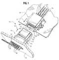
- the inventionis embodied in a mating connector assembly, generally designated 24, which includes a backplane connector assembly, generally designated 26, mateable with a daughterboard connector assembly, generally designated 28.
- the backplane connector assemblyis mounted in an aperture 30 in a substrate, panel or backplane which, in the preferred embodiment, is a printed circuit board.
- backplane 32can be considered the "motherboard” herein.
- the daughterboard connector assemblyis mounted on a top surface of a second printed circuit board 34 which is considered the "daughterboard" herein.
- Backplane connector assembly 26includes an adapter, generally designated 36, which is mounted in aperture 30 in motherboard 32.
- Fiber optic connector modulesgenerally designated 38, are inserted into adapter 36, through aperture 30, from the front of backplane 32.
- Each fiber optic connector moduleis terminated to a multi-fiber cable 40.
- Each cableis a flat or "ribbon" cable having a plurality of optical fibers.
- daughterboard connector assembly 28After daughterboard connector assembly 28 is mounted on daughterboard 34, four fiber optic connector modules, generally designated 42, are inserted into the back of the connector housing, as described hereinafter. Each module 42 is terminated to a flat, multi-fiber cable 44 similar to fiber optic cables 40.
- Backplane connector assembly 26 and daughterboard connector assembly 28are mateable in the direction of arrows "A" (Figs. 1 and 2) to a mated condition shown in Figure 3, wherein the fibers of cables 40 and 44 are functionally connected.
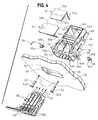
- adapter 36includes a housing 46 which may be fabricated of molded plastic material.
- the housingdefines a front mating end 46a and a rear terminating end 46b.
- the front mating endis open, as at 46c, and through which the ferrules (described hereinafter) of fiber optic connector modules 38 can project.
- Terminating end 46bis open, as at 46d, for receiving connector modules 38 in the direction of arrows "B".
- Housing 46 of adapter 36has an outwardly projecting alignment rib 48 on each opposite side thereof and extending in the mating direction of the connector assembly, for purposes described hereinafter.
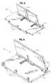
- FIG. 5shows a shutter assembly, generally designated 50, for closing opening 46b of adapter 46
- Figure 6shows a shutter assembly, generally designated 52, for closing mating opening 46c of the adapter.
- Shutter assembly 50includes a pair of spring-loaded shutters 50a which close opening 46d on opposite sides of an interior partition 54 (Fig. 4).
- the shutter membersare pivotally mounted on a plate 50b which includes a plurality of pegs 50c which are press-fit into holes 56 in adapter housing 46.
- shutter 52a of shutter assembly 52is spring-loaded and is mounted on a plate 52b which has a plurality of pegs 52c which are press-fit into a plurality of holes 58 in adapter housing 46.
- Shutters 50a and 52aprovide dust covers for the interior of adapter 36.
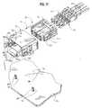
- a pair of T-nutsare floatingly mounted to adapter 36 and receive a pair of rivets 62 insertable in the direction of arrows "C" through a pair of mounting holes 64 in the backplane.
- the rivetshave enlarged head portions 62a which will engage the surface of the backplane.
- Mounting holes 64are spaced on opposite sides of opening 30.
- each T-nut 60includes a shank portion 60a and an enlarged head 60b.
- a mounting flange, generally designed 66,is molded integrally with each opposite side of adapter housing 46.
- Each flange 66includes an interior cavity 66a which receives head portion 60b of one of the T-nuts 60.
- a passage 66bextends through flange 66 toward backplane 32 in communication with cavity 66a for receiving shank portion 60a of the T-nut.
- head portion 60bare smaller than cavity 66a so that the head portion can float within the cavity
- the cross dimensions of shank portion 60aare less than the dimensions of passage 66b so that the shank portion can float within the passage
- the length of shank portion 60ais greater than the thickness of a wall portion 67 of flange 66 below the head portion (i.e., the thickness indicated by double-headed arrow "D" (Fig. 7). Therefore, when rivet 62 tightens the T-nut onto surface 32a of backplane 32, the adapter does not become tightened to the backplane and is allowed to float relative thereto.
- passage 66bhas a restricted mouth, as at 66e, so that the T-nut can be snap-fit into flange 66 to mount the nut to adapter housing 46.
- rivet 62equally could be a threaded fastener, such as a screw, for threadingly engaging the T-nut.
- FIGs 8-10show one of the fiber optic connector modules 38 which are inserted into adapter 36 as described above.
- each module 38includes a ferrule 68 terminated to one of the multi-fiber cables 40 with ends 40a (Fig. 8) of the fibers exposed at a mating face 68a of the ferrule.
- the ferruleincludes a pair of alignment holes 68b opening into mating face 68a.
- the ferruleis captured by a manually manipulatable housing, generally designated 70, which includes a front portion 70a which actually captures the ferrule, and a rear portion defined by a pair of laterally spaced arms 70b that are graspable between an operator's fingers.
- Figure 10shows that ferrule 68 has a peripheral flange 68c.
- the front portion 70a of housing 70includes a pair of forward latch hooks 70c on two opposite sides of the housing and a pair of flexible latch arms 70d on the other two opposite sides of the housing.
- each latch arm 70dincludes an inside chamfered latch hook 70e.
- Latch hooks 70cengage the front of flange 68c of the ferrule
- latch hooks 70e on latch arms 70dengage the rear edges of flange 68c to hold the ferrule encapsulated within front portion 70a of housing 70.
- manually graspable arms 70include serrations 71 on the outsides thereof to facilitate manual grasping thereof.
- a latch block 70fprojects outwardly from each arm for latching engagement within adapter 36.
- Each arm 70balso includes an interior channel 70g for guiding ferrule 68 into front portion 70a of the housing.
- FIG 10shows that ferrule 68 is insertable into housing 70 of connector module 38 in the direction of arrow "E".
- the ferrulemoves within channels 70g of arms 70b and through an open rear end 70h of front portion 70a of the housing.
- the ferrulebecomes latched in a position projecting out of an open front end 70i (Fig. 9) of the housing and is locked in the position shown in Figure 8, with the ferrule projecting forwardly of the manually manipulatable housing.
- FIGs 11-13show daughterboard connector assembly 28 to include a two-part housing defined by a front housing part, generally designated 72, and a rear housing part, generally designated 74.
- the rear housing partis insertable into the front housing part in the direction of arrow "F" (Fig. 11).
- Rear housing part 74has a flexible latch arm 74a with a latch hook 74b which latches behind a front latch shoulder 72a (Fig. 13) when the two housing parts are initially assembled.
- Figure 13also shows a second latch shoulder 72b which is located rearwardly of latch shoulder 72a, for purposes described hereinafter.
- Each housing part 72 and 74may be a one-piece structure unitarily molded of dielectric material such as plastic or the like.
- a systemfor mounting front housing part 72 of daughterboard connector assembly 28 on daughterboard 34 with considerable precision.
- the daughterboardhas a pre-placement hole 76 spaced between a pair of positioning holes 78 of as seen in Figure 11.
- a pair of rivets 80are insertable through positioning holes 78.
- a pre-positioning peg 82projects downwardly from a bottom surface 72d of front housing part 72 for insertion into pre-placement hole 76 with substantially zero insertion forces.
- hole 76is larger than peg 82.
- a pair of positioning pegs 84project downwardly from surface 70d for insertion into positioning holes 78 in daughterboard 34 by a press-fit to precisely fix the housing on the substrate.
- Peg 82is solid, but pegs 84 are hollow for receiving rivets 80 therethrough to solidly lock the front housing part to the daughterboard.
- Pre-placement peg 82is longer than positioning pegs 84 so that it is easy for an operator to locate and insert pre-placement peg 82 into pre-placement hole 76. The housing then can be easily pivoted about peg 82 until positioning pegs 84 are aligned with positioning holes 78.
- positioning pegs 84are provided with crushable ribs 84a on the exterior thereof and which are crushed or deformed when pegs 84 are press-fit into holes 78.
- Bottom surface 72d of front housing part 72is recessed, as at 86, around each positioning peg 84. This recessed area is provided for receiving any plastic material, such as crushable ribs 84a, which might be shaved off of positioning pegs 84 when they are press-fit into positioning holes 78. This ensures that bottom surface 72d of front housing part 72 is mounted flush on the flat top surface of daughterboard 34.
- front housing part 72includes a pair of alignment flanges 88 at opposite sides of an open mating end 72e of the front housing part.
- Each flangehas an outwardly chamfered or flared distal end 88a which is engageable by the front edges 90 (Fig.1) of adapter 36 upon mating of the two connector assemblies.
- flared distal ends 88aallow for a degree of misalignment between the connector assemblies in an "X" direction generally perpendicular to mating direction "A" (Fig. 1) of the connectors, the "X" direction being generally parallel to daughterboard 34.
- Alignment flanges 88have grooves or slots 88b on the insides thereof for receiving alignment ribs 48 (Fig. 1) on opposite sides of adapter housing 46. Slots 88b have flared mouths 88c which are engageable by the distal ends of alignment ribs 48 to allow for a degree of misalignment between the two connector assemblies in a "Y" direction generally perpendicular to mating direction "A” as well as generally perpendicular to the aforesaid "X" direction and daughterboard 44.
- alignment flanges 88with the outwardly flared distal ends 88a thereof in combination with flared mouths 88c of slots 88b, are unique in utilizing a singular structure to allow for misalignment in two different "X" and "Y" directions.
- a bottom flange 92projects forwardly of front housing part 72 flush with bottom surface 72d (Fig. 12) of the front housing part.
- the flangehas a bottom hook portion 92a and a top chamfered portion 92b.
- the bottom hook portionoverlaps an edge 94 of daughterboard 34.
- the top chamfered portion 92bis engageable by the front bottom edge of adapter housing 46 to prevent the bottom edge of the housing from "stubbing" the front edge of the daughterboard during mating of the connector assemblies.
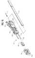
- FIGs 14-19show in greater detail one of the fiber optic connector modules 42 inserted into rear housing part 74 of daughterboard connector assembly 28.
- each module 42includes a ferrule 96 for terminating multi-fiber cable 44, with a resilient boot 98 providing strain-relief for the cable.
- the ferruleincludes a pair of through holes or passages 96a (Fig. 15) for receiving a pair of alignment pins 100 fixed to a pin keeper 102 which abuts against the rear of ferrule 96 so that the distal ends of alignment pins 100 project forwardly of a front mating face 96b of ferrule 96.
- a coil spring 104is fixed to a rear end of pin keeper 102 as described hereinafter, and a spring pusher member 106 is fixed to the rear end of the coil spring.
- Both pin keeper 102 and pusher member 106may be fabricated of molded plastic material.
- An integral, flexible latch arm 107projects outwardly from the pusher member for latching the fiber optic connector module within rear housing part 74 of daughterboard connector assembly 28.
- Figure 16shows that pin keeper 102 has a receptacle 102a at a rear end thereof for receiving a front end of coil spring 104, along with a locking flange 102b for locking with a coil at the front end of the spring.
- one of the locking flanges 102bare disposed at each opposite side of receptacle 102a of pin keeper 102.
- Figure 17shows pusher member 106 to have a front receptacle 106a at a front end thereof for receiving a rear end of coil spring 104.
- a locking flange 106bis disposed at each opposite side of receptacle 106a for locking with a coil at the rear end of the coil spring.
- Figures 18 and 19show the procedure for assembling coil spring 104 between pin keeper 102 and pusher member 106 and locking the coil spring to those components.
- coil spring 104is oval in cross-configuration.
- a tool 110has a generally oval shaft 112 for insertion in the direction of arrow "G” into oval coil spring 104. The tool then is rotated in the direction of arrow "H” to effectively rotate the coil spring and cause the front open end coil 104a to lock behind flanges 102b (Fig. 16) of pin keeper 102.
- This subassemblythen is positioned as shown in Figure 19 so that the opposite open end coil 104b (Fig. 18) is aligned with locking flanges 106b of pusher member 106.
- Shaft 112 of tool 110then is inserted in the direction of arrow "I” (Fig. 19) into a rectangular hole 114 in pin keeper 102 and into coil spring 104, and the tool rotated in the direction of arrow "J".
- Alignment pins 100then are fixed within slots 116 (Fig. 19) so that they extend from the pin keeper as seen in Figure 15.
- Boot 98then is inserted into opening 114 of the pin keeper; ferrule 96 is positioned onto alignment pins 100; fiber optic cable 44 is inserted into and through the entire assembly in the direction of arrow "K” (Fig. 15); and the alignment pins and cable are epoxied within the ferrule so that an entire self-contained unit is formed as shown in Figure 14.
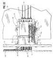
- Figures 20-22show the mating procedure of backplane connector assembly 26 and daughterboard connector assembly 28 in the direction of arrows "A", after the backplane assembly is mounted to backplane or motherboard 32 and after the daughterboard connector assembly is mounted to daughterboard 34. These depictions also show that fiber optic cables 40 are engaged with yet another substrate or board 120.
- Figure 20best shows that adapter 36 of backplane connector assembly 26 has a pair of actuator arms 122 spaced outwardly from opposite sides thereof. The distal ends of actuator arms 122 are formed with a latch hook 122a and a forwardly facing chamfer 122b.
- Backplane connector assembly 26 and daughterboard connector assembly 28are mateable in a two-step process represented by Figures 21 and 22.
- hooks 122a of actuator arms 122snap behind a pair of preliminary latch shoulders 124 (Figs. 1 and 20) of rear housing part 74 of daughterboard connector assembly 28.
- Latch hooks 74b on the ends of latch arms 74a at opposite sides of the rear housing partalready have latched behind latch shoulders 72a (Fig. 14) of front housing part 72. This prevents any rearward movement of any part of daughterboard connector assembly 28 in response to the preliminary latching of backplane connector assembly 26 thereto.
Landscapes
- Physics & Mathematics (AREA)
- General Physics & Mathematics (AREA)
- Optics & Photonics (AREA)
- Mechanical Coupling Of Light Guides (AREA)
- Details Of Connecting Devices For Male And Female Coupling (AREA)
Abstract
Description
Claims (12)
- An alignment system between a pair of connectors (36,28) mateablein a given mating direction (A), comprising:a first connector (36) including a housing (46) having an alignmentprojection (48) on one side thereof extending generally transversely of said matingdirection (A); anda second connector (28) including a housing (72) having an alignmentflange (88) projecting forwardly thereof generally in said mating direction (A).said alignment flange (88) being flared (88a) outwardly generallytransversely of said mating direction (A) for engaging the housing (46) of the firstconnector (36) during mating and allowing a degree of misalignment between theconnectors (36,28) in an "X" direction generally perpendicular to the mating direction(A), andsaid alignment flange (88) including a slot (88b) for receiving thealignment projection (48) of the first connector (36), the slot having a flared mouth (88c)allowing a degree of misalignment between the connectors in a "Y" direction generallyperpendicular to the mating direction (A) and generally perpendicular to said "X"direction.
- The alignment system of claim 1 wherein said alignment projection onthe housing of the first connector (36) comprises a projecting rib (48) which is elongatedin said mating direction (A).
- The alignment system of claim 1, including a pair of said alignmentflanges (88) on the housing (72) of the second connector (28), the flanges being spacedtransversely of said mating direction (A) and between which the second connector (28)is mated with the first connector (36).
- The alignment system of claim 3 wherein said transversely spacedflanges comprise forwardly projecting arms (88) having distal ends with inside surfaces(88a) which are divergingly flared away from the housing (72) of the second connector(28).
- The alignment system of claim 4 wherein each of said arms (88)includes one of said slots (88b) in the inside thereof, each slot having said flared mouth(88c), and the housing (46) of the first connector (36) having one of said alignmentprojections (48) on opposite sides thereof for receipt in said slots (88c).
- The alignment system of claim 1 wherein said first connectorcomprises an open-ended adapter (36), with one open end (46c) for mating with thesecond connector (28).
- The alignment system of claim 6 wherein said second connectorcomprises a fiber optic connector (28).
- An alignment system between an adapter (36) and a fiber opticconnector (28) mateable in a given mating direction (A), comprising:an adapter (36) including a housing (46) having an open end (46c) and analignment projection (48) on one side thereof extending generally transversely of saidmating direction (A); anda fiber optic connector (28) including a housing (72) having a pair oftransversely spaced alignment arms (88) projecting forwardly thereof generally in saidmating direction (A) and between which the adapter (36) is mated with the connector.the arms having distal ends (88a) which are divergingly flared away from the housing forallowing a degree of misalignment between the adapter and the connector in an "X"direction generally perpendicular to the mating direction (A), andsaid alignment arms (88) including slots (88b) forreceiving the alignmentprojections (48) of the adapter, the slots having flared mouths (88c) allowing a degree ofmisalignment between the adapter and the connector in a "Y" direction (A) generallyperpendicular to the mating direction and generally perpendicular to said "X" direction.
- The alignment system of claim 8 wherein said alignment projectionson the housing (46) of the adapter (36) comprise projecting ribs (48) which are elongatedin the mating direction (A).
- A connector (28) for mounting on a surface of a substrate (34) at anedge (94) thereof, comprising a connector housing (72) adapted for mounting on thesurface of the substrate with a mating end (72e) of the housing adjacent the edge (94) ofthe substrate (34), and a chamfered member (92) overlapping the edge of the substratefor guiding a complementary connecting device (36) into mating engagement with saidmating end of the housing.
- The connector of claim 1 wherein said chamfered member (92) is anintegral part of the connector housing (72).
- The connector of claim 11 wherein said connector housing (72) ismolded of plastic material with the chamfered member (92) being molded integrallytherewith.
Priority Applications (1)
| Application Number | Priority Date | Filing Date | Title |
|---|---|---|---|
| EP08006848AEP1942359A3 (en) | 1999-12-07 | 2000-12-04 | Alignment system for mating connectors |
Applications Claiming Priority (2)
| Application Number | Priority Date | Filing Date | Title |
|---|---|---|---|
| US454853 | 1999-12-07 | ||
| US09/454,853US6371657B1 (en) | 1999-12-07 | 1999-12-07 | Alignment system for mating connectors |
Related Child Applications (1)
| Application Number | Title | Priority Date | Filing Date |
|---|---|---|---|
| EP08006848ADivisionEP1942359A3 (en) | 1999-12-07 | 2000-12-04 | Alignment system for mating connectors |
Publications (2)
| Publication Number | Publication Date |
|---|---|
| EP1107031A1true EP1107031A1 (en) | 2001-06-13 |
| EP1107031B1 EP1107031B1 (en) | 2008-04-09 |
Family
ID=23806364
Family Applications (2)
| Application Number | Title | Priority Date | Filing Date |
|---|---|---|---|
| EP08006848AWithdrawnEP1942359A3 (en) | 1999-12-07 | 2000-12-04 | Alignment system for mating connectors |
| EP00126631AExpired - LifetimeEP1107031B1 (en) | 1999-12-07 | 2000-12-04 | Alignment system for mating connectors |
Family Applications Before (1)
| Application Number | Title | Priority Date | Filing Date |
|---|---|---|---|
| EP08006848AWithdrawnEP1942359A3 (en) | 1999-12-07 | 2000-12-04 | Alignment system for mating connectors |
Country Status (8)
| Country | Link |
|---|---|
| US (1) | US6371657B1 (en) |
| EP (2) | EP1942359A3 (en) |
| JP (3) | JP3463244B2 (en) |
| KR (1) | KR100367392B1 (en) |
| CN (1) | CN1203342C (en) |
| DE (1) | DE60038529T2 (en) |
| SG (1) | SG97983A1 (en) |
| TW (1) | TW504059U (en) |
Cited By (52)
| Publication number | Priority date | Publication date | Assignee | Title |
|---|---|---|---|---|
| EP1391762A1 (en)* | 2002-08-16 | 2004-02-25 | Agilent Technologies, Inc. | Optical connecting device for coupling connectors to an apparatus with multiple ports |
| WO2006127397A1 (en)* | 2005-05-25 | 2006-11-30 | Adc Telecommunications, Inc. | Fiber optic adapter module consisting of plurality of integrally formed adapters |
| WO2006138460A1 (en)* | 2005-06-17 | 2006-12-28 | Fiber Optics Network Solutions Corp. | Compact blind mateable optical splitter |
| US7346254B2 (en) | 2005-08-29 | 2008-03-18 | Adc Telecommunications, Inc. | Fiber optic splitter module with connector access |
| US7376322B2 (en) | 2004-11-03 | 2008-05-20 | Adc Telecommunications, Inc. | Fiber optic module and system including rear connectors |
| US7391954B1 (en) | 2007-05-30 | 2008-06-24 | Corning Cable Systems Llc | Attenuated optical splitter module |
| US7400813B2 (en) | 2005-05-25 | 2008-07-15 | Adc Telecommunications, Inc. | Fiber optic splitter module |
| WO2009048680A1 (en)* | 2007-08-06 | 2009-04-16 | Adc Telecommunications, Inc. | Fiber optic enclosure with internal cable spool |
| US7715679B2 (en) | 2007-05-07 | 2010-05-11 | Adc Telecommunications, Inc. | Fiber optic enclosure with external cable spool |
| US7869682B2 (en) | 2007-09-05 | 2011-01-11 | Adc Telecommunications, Inc. | Fiber optic enclosure with tear-away spool |
| US8265447B2 (en) | 2008-09-16 | 2012-09-11 | Adc Telecommunications, Inc. | Modular fiber optic enclosure with external cable spool |
| US8346045B2 (en) | 2006-02-13 | 2013-01-01 | Adc Telecommunications, Inc. | Fiber optic splitter module |
| US8422847B2 (en) | 2009-07-21 | 2013-04-16 | Adc Telecommunications, Inc. | Rapid universal rack mount enclosure |
| US8467651B2 (en) | 2009-09-30 | 2013-06-18 | Ccs Technology Inc. | Fiber optic terminals configured to dispose a fiber optic connection panel(s) within an optical fiber perimeter and related methods |
| US8520996B2 (en) | 2009-03-31 | 2013-08-27 | Corning Cable Systems Llc | Removably mountable fiber optic terminal |
| US8792767B2 (en) | 2010-04-16 | 2014-07-29 | Ccs Technology, Inc. | Distribution device |
| US8798427B2 (en) | 2007-09-05 | 2014-08-05 | Corning Cable Systems Llc | Fiber optic terminal assembly |
| US8837940B2 (en) | 2010-04-14 | 2014-09-16 | Adc Telecommunications, Inc. | Methods and systems for distributing fiber optic telecommunication services to local areas and for supporting distributed antenna systems |
| US8879882B2 (en) | 2008-10-27 | 2014-11-04 | Corning Cable Systems Llc | Variably configurable and modular local convergence point |
| US8909019B2 (en) | 2012-10-11 | 2014-12-09 | Ccs Technology, Inc. | System comprising a plurality of distribution devices and distribution device |
| US9004778B2 (en) | 2012-06-29 | 2015-04-14 | Corning Cable Systems Llc | Indexable optical fiber connectors and optical fiber connector arrays |
| US9049500B2 (en) | 2012-08-31 | 2015-06-02 | Corning Cable Systems Llc | Fiber optic terminals, systems, and methods for network service management |
| US9188760B2 (en) | 2011-12-22 | 2015-11-17 | Adc Telecommunications, Inc. | Mini rapid delivery spool |
| US9219546B2 (en) | 2011-12-12 | 2015-12-22 | Corning Optical Communications LLC | Extremely high frequency (EHF) distributed antenna systems, and related components and methods |
| US9239442B2 (en) | 2010-04-27 | 2016-01-19 | Adc Communications (Shanghai) Co., Ltd. | Fiber optic module and chassis |
| US9261663B2 (en) | 2010-06-18 | 2016-02-16 | Adc Communications (Shanghai) Co., Ltd. | Fiber optic distribution terminal and method of deploying fiber distribution cable |
| US9301030B2 (en) | 2013-11-11 | 2016-03-29 | Commscope Technologies Llc | Telecommunications module |
| US9323020B2 (en) | 2008-10-09 | 2016-04-26 | Corning Cable Systems (Shanghai) Co. Ltd | Fiber optic terminal having adapter panel supporting both input and output fibers from an optical splitter |
| US9395509B2 (en) | 2014-06-23 | 2016-07-19 | Commscope Technologies Llc | Fiber cable fan-out assembly and method |
| US9417401B2 (en) | 2011-09-06 | 2016-08-16 | Commscope Technologies Llc | Adapter for fiber optic module |
| US9513445B2 (en) | 2007-05-31 | 2016-12-06 | Corning Optical Communications LLC | Direct-connect optical splitter module |
| US9547144B2 (en) | 2010-03-16 | 2017-01-17 | Corning Optical Communications LLC | Fiber optic distribution network for multiple dwelling units |
| US9547145B2 (en) | 2010-10-19 | 2017-01-17 | Corning Optical Communications LLC | Local convergence point for multiple dwelling unit fiber optic distribution network |
| US9753238B2 (en) | 2011-03-31 | 2017-09-05 | Commscope Technologies Llc | Adapter plate for fiber optic module |
| US9995898B2 (en) | 2010-06-23 | 2018-06-12 | Commscope Technologies Llc | Telecommunications assembly |
| US10031305B2 (en) | 2012-12-19 | 2018-07-24 | CommScope Connectivity Belgium BVBA | Distribution device with incrementally added splitters |
| US10110307B2 (en) | 2012-03-02 | 2018-10-23 | Corning Optical Communications LLC | Optical network units (ONUs) for high bandwidth connectivity, and related components and methods |
| US10162131B2 (en) | 2015-08-21 | 2018-12-25 | Commscope Technologies Llc | Telecommunications module |
| US10222571B2 (en) | 2016-04-07 | 2019-03-05 | Commscope Technologies Llc | Telecommunications module and frame |
| WO2019120618A1 (en)* | 2017-12-19 | 2019-06-27 | Eaton Intelligent Power Limited | Connectors for fiber optic cables |
| US10371914B2 (en) | 2011-06-24 | 2019-08-06 | Commscope Technologies Llc | Fiber termination enclosure with modular plate assemblies |
| US10514520B2 (en) | 2014-10-27 | 2019-12-24 | Commscope Technologies Llc | Fiber optic cable with flexible conduit |
| US10606009B2 (en) | 2015-12-01 | 2020-03-31 | CommScope Connectivity Belgium BVBA | Cable distribution system with fan out devices |
| US10606019B2 (en) | 2015-07-31 | 2020-03-31 | Commscope Technologies Australia Pty Ltd | Cable breakout assembly |
| US10637220B2 (en) | 2016-01-28 | 2020-04-28 | CommScope Connectivity Belgium BVBA | Modular hybrid closure |
| USRE48063E1 (en) | 2007-01-13 | 2020-06-23 | Commscope Technologies Llc | Fiber optic cable distribution box |
| US10732370B2 (en) | 2014-06-17 | 2020-08-04 | CommScope Connectivity Belgium BVBA | Cable distribution system |
| US10890730B2 (en) | 2016-08-31 | 2021-01-12 | Commscope Technologies Llc | Fiber optic cable clamp and clamp assembly |
| US10914909B2 (en) | 2016-10-13 | 2021-02-09 | Commscope Technologies Llc | Fiber optic breakout transition assembly incorporating epoxy plug and cable strain relief |
| US11131821B2 (en) | 2016-03-18 | 2021-09-28 | Commscope Technologies Llc | Optic fiber cable fanout conduit arrangements; components, and methods |
| US11131822B2 (en) | 2017-05-08 | 2021-09-28 | Commscope Technologies Llc | Fiber-optic breakout transition assembly |
| USRE49374E1 (en) | 2003-09-08 | 2023-01-17 | Commscope Technologies Llc | Fiber optic cable and furcation module |
Families Citing this family (40)
| Publication number | Priority date | Publication date | Assignee | Title |
|---|---|---|---|---|
| US5883995A (en) | 1997-05-20 | 1999-03-16 | Adc Telecommunications, Inc. | Fiber connector and adapter |
| US6422760B1 (en)* | 2001-01-31 | 2002-07-23 | Molex Incorporated | Fiber optic connector module |
| US7167499B2 (en)* | 2001-04-18 | 2007-01-23 | Tcz Pte. Ltd. | Very high energy, high stability gas discharge laser surface treatment system |
| US6688780B2 (en) | 2002-02-07 | 2004-02-10 | Amphenol Corporation | Cantilevered shutter for optical adapter |
| US7144163B2 (en)* | 2003-01-27 | 2006-12-05 | Fujikura Ltd. | Optical connector with shutter, shutter unit, and inner piece |
| JP2005156603A (en)* | 2003-11-20 | 2005-06-16 | Molex Japan Co Ltd | Optical fiber adaptor |
| US7835006B2 (en)* | 2004-11-05 | 2010-11-16 | Nomadics, Inc. | Optical fiber sensors using grating-assisted surface plasmon-coupled emission (GASPCE) |
| US7364366B2 (en)* | 2005-02-02 | 2008-04-29 | Viasystems Group, Inc. | Circuit board assembly having a guide insert |
| US7484530B2 (en)* | 2005-04-22 | 2009-02-03 | Parker-Hannifin Corporation | Dual purpose alignment and fluid coupling |
| JP4858750B2 (en)* | 2005-10-06 | 2012-01-18 | 日本電気株式会社 | Information processing device |
| JP4728917B2 (en)* | 2006-09-06 | 2011-07-20 | 日本電信電話株式会社 | Optical connector |
| JP4863319B2 (en)* | 2009-05-19 | 2012-01-25 | 日本航空電子工業株式会社 | Optical connector |
| CN102315558B (en)* | 2010-07-08 | 2013-11-13 | 富士康(昆山)电脑接插件有限公司 | Plug connector and socket connector |
| US20140301700A1 (en)* | 2011-07-28 | 2014-10-09 | Takahiro Matsubara | Optical connector, optical transmission module, and method for producing optical connector |
| JP2013029624A (en)* | 2011-07-28 | 2013-02-07 | Kyocera Corp | Optical connector and optical transmission module |
| CN104040395B (en) | 2012-01-06 | 2016-06-01 | 惠普发展公司,有限责任合伙企业 | Optics is connected to the connector modules of electronic installation |
| JP6244173B2 (en)* | 2012-11-09 | 2017-12-06 | 株式会社フジクラ | Optical connector |
| CN107656339B (en)* | 2013-11-12 | 2019-08-13 | 华为技术有限公司 | Fiber connector, fiber adapter and optical fiber connector |
| WO2015087385A1 (en)* | 2013-12-09 | 2015-06-18 | 株式会社日立製作所 | Optical wiring board, optical wiring board manufacturing method, and information processing apparatus using optical wiring board |
| WO2016068892A1 (en)* | 2014-10-29 | 2016-05-06 | Hewlett Packard Enterprise Development Lp | Optical connector assembly apparatus |
| WO2016071998A1 (en)* | 2014-11-06 | 2016-05-12 | 株式会社日立製作所 | Substrate and device having same |
| WO2016121059A1 (en)* | 2015-01-29 | 2016-08-04 | 株式会社日立製作所 | Optical interconnection device |
| CN108352657A (en) | 2015-11-17 | 2018-07-31 | 惠普发展公司有限责任合伙企业 | Equipment connector |
| JP2018036477A (en)* | 2016-08-31 | 2018-03-08 | 住友電気工業株式会社 | Optical connection structure |
| TWI608261B (en)* | 2016-11-29 | 2017-12-11 | 普泰光電股份有限公司 | Optical fiber adapter with shutter member |
| US10409010B2 (en)* | 2017-01-11 | 2019-09-10 | Eaton Corporation | Connectors for fiber optic cables |
| US11333836B2 (en) | 2017-01-30 | 2022-05-17 | Senko Advanced Components, Inc. | Adapter for optical connectors |
| US10116090B2 (en)* | 2017-03-17 | 2018-10-30 | Hosiden Corporation | Female connector and connection structure of female connector and male connector |
| US10989884B2 (en) | 2017-04-07 | 2021-04-27 | Senko Advanced Components, Inc. | Behind the wall optical connector with reduced components |
| US10754098B2 (en) | 2017-04-07 | 2020-08-25 | Senko Advanced Components, Inc. | Behind the wall optical connector with reduced components |
| US10209461B2 (en)* | 2017-04-07 | 2019-02-19 | Senko Advanced Components | Behind the wall optical connector with reduced components |
| US10401576B2 (en) | 2017-05-10 | 2019-09-03 | Senko Advanced Components, Inc. | MPO micro-latch-lock connector |
| US10359576B2 (en) | 2017-06-15 | 2019-07-23 | Senko Advanced Components, Inc. | SC low profile connector with optional boot |
| CN110596826B (en)* | 2018-06-30 | 2021-11-09 | 中航光电科技股份有限公司 | Socket with improved structure |
| EP4592721A2 (en)* | 2018-11-14 | 2025-07-30 | US Conec, Ltd | Guide pin insert for guide pins in an adapter |
| US12038613B2 (en) | 2019-03-28 | 2024-07-16 | Senko Advanced Components, Inc. | Behind-the-wall optical connector and assembly of the same |
| US11579379B2 (en) | 2019-03-28 | 2023-02-14 | Senko Advanced Components, Inc. | Fiber optic adapter assembly |
| JP7036772B2 (en)* | 2019-05-27 | 2022-03-15 | 矢崎総業株式会社 | Optical connector |
| EP4004619A4 (en) | 2019-07-26 | 2023-08-09 | CommScope Technologies LLC | FIBER OPTIC ADAPTERS CONVERTIBLE BETWEEN DIFFERENT TYPES OF POLARITY |
| US12386124B2 (en)* | 2022-11-30 | 2025-08-12 | Mellanox Technologies, Ltd. | Device for holding a plurality of ferrules against a respective plurality of receptacles |
Citations (3)
| Publication number | Priority date | Publication date | Assignee | Title |
|---|---|---|---|---|
| US4611887A (en)* | 1983-02-24 | 1986-09-16 | Amp Incorporated | Fiber optic connector assembly and wall outlet thereof |
| WO1988005925A1 (en)* | 1987-02-03 | 1988-08-11 | American Telephone & Telegraph Company | Duplex optical fiber connector |
| US5909526A (en)* | 1998-04-08 | 1999-06-01 | Molex Incorporated | Fiber optic connector assembly |
Family Cites Families (11)
| Publication number | Priority date | Publication date | Assignee | Title |
|---|---|---|---|---|
| JP2771870B2 (en) | 1989-12-01 | 1998-07-02 | 日本電信電話株式会社 | Optical connector |
| US5121454A (en) | 1989-11-24 | 1992-06-09 | Nippon Telegraph And Telephone Corporation | Optical connector |
| US5082344A (en)* | 1990-03-09 | 1992-01-21 | Mulholland Denis G | Adapter assembly with improved receptacle for a push-pull coupling type of optical fiber connector |
| US5073045A (en)* | 1991-03-25 | 1991-12-17 | Amp Incorporated | Connector with improved clip connector half |
| JPH0589926A (en)* | 1991-09-27 | 1993-04-09 | Fujikura Ltd | Low inserting force connector |
| GB9307488D0 (en) | 1993-04-08 | 1993-06-02 | Amp Holland | Optical fibre connector latching mechanism |
| EP0805366A1 (en)* | 1996-05-02 | 1997-11-05 | Harting KGaA | Connector |
| US5909926A (en) | 1996-09-04 | 1999-06-08 | Hi-Tech Seating Products, Inc. | Vehicle seating assembly |
| US5903426A (en)* | 1996-10-18 | 1999-05-11 | Balluff, Inc. | Overvoltage protection apparatus for a data interface |
| SG78280A1 (en)* | 1997-12-03 | 2001-02-20 | Molex Inc | Circuit board mounted electrical connector assembly and method of using same |
| KR20000011169A (en)* | 1998-07-28 | 2000-02-25 | 다니시타 다다시 | Auxiliary power source device for portable electronic instrument |
- 1999
- 1999-12-07USUS09/454,853patent/US6371657B1/ennot_activeExpired - Lifetime
- 2000
- 2000-11-16SGSG200006845Apatent/SG97983A1/enunknown
- 2000-11-27TWTW089220559Upatent/TW504059U/ennot_activeIP Right Cessation
- 2000-12-04EPEP08006848Apatent/EP1942359A3/ennot_activeWithdrawn
- 2000-12-04EPEP00126631Apatent/EP1107031B1/ennot_activeExpired - Lifetime
- 2000-12-04DEDE60038529Tpatent/DE60038529T2/ennot_activeExpired - Fee Related
- 2000-12-04JPJP2000403840Apatent/JP3463244B2/ennot_activeExpired - Fee Related
- 2000-12-06CNCNB001360663Apatent/CN1203342C/ennot_activeExpired - Lifetime
- 2000-12-06KRKR10-2000-0073563Apatent/KR100367392B1/ennot_activeExpired - Fee Related
- 2003
- 2003-04-21JPJP2003115663Apatent/JP2003294982A/enactivePending
- 2006
- 2006-01-18JPJP2006000294Upatent/JP3120395U/ennot_activeExpired - Lifetime
Patent Citations (3)
| Publication number | Priority date | Publication date | Assignee | Title |
|---|---|---|---|---|
| US4611887A (en)* | 1983-02-24 | 1986-09-16 | Amp Incorporated | Fiber optic connector assembly and wall outlet thereof |
| WO1988005925A1 (en)* | 1987-02-03 | 1988-08-11 | American Telephone & Telegraph Company | Duplex optical fiber connector |
| US5909526A (en)* | 1998-04-08 | 1999-06-01 | Molex Incorporated | Fiber optic connector assembly |
Cited By (166)
| Publication number | Priority date | Publication date | Assignee | Title |
|---|---|---|---|---|
| US6908234B2 (en) | 2002-08-16 | 2005-06-21 | Agilent Technologies, Inc. | Optical connecting device for coupling connectors to an apparatus with multiple ports |
| EP1391762A1 (en)* | 2002-08-16 | 2004-02-25 | Agilent Technologies, Inc. | Optical connecting device for coupling connectors to an apparatus with multiple ports |
| USRE49374E1 (en) | 2003-09-08 | 2023-01-17 | Commscope Technologies Llc | Fiber optic cable and furcation module |
| US8331753B2 (en) | 2004-11-03 | 2012-12-11 | Adc Telecommunications, Inc. | Fiber optic module and system including rear connectors |
| US8023791B2 (en) | 2004-11-03 | 2011-09-20 | Adc Telecommunications, Inc. | Fiber optic module and system including rear connectors |
| US9213159B2 (en) | 2004-11-03 | 2015-12-15 | Commscope Technologies Llc | Fiber optic module and system including rear connectors |
| US8705928B2 (en) | 2004-11-03 | 2014-04-22 | Adc Telecommunications, Inc. | Fiber optic module and system including rear connectors |
| US10359591B2 (en) | 2004-11-03 | 2019-07-23 | Commscope Technologies Llc | Fiber optic module and system including rear connectors |
| US7376322B2 (en) | 2004-11-03 | 2008-05-20 | Adc Telecommunications, Inc. | Fiber optic module and system including rear connectors |
| US11280974B2 (en) | 2004-11-03 | 2022-03-22 | Comm Scope Technologies LLC | Fiber optic module and system including rear connectors |
| US7593614B2 (en) | 2004-11-03 | 2009-09-22 | Adc Telecommunications, Inc. | Fiber optic module and system including rear connectors |
| US9964726B2 (en) | 2004-11-03 | 2018-05-08 | Commscope Technologies Llc | Fiber optic module and system including rear connectors |
| US7376323B2 (en) | 2005-05-25 | 2008-05-20 | Adc Telecommunications, Inc. | Fiber optic adapter module |
| US7706656B2 (en) | 2005-05-25 | 2010-04-27 | Adc Telecommunications, Inc. | Fiber optic adapter module |
| US7400813B2 (en) | 2005-05-25 | 2008-07-15 | Adc Telecommunications, Inc. | Fiber optic splitter module |
| US7835611B2 (en) | 2005-05-25 | 2010-11-16 | Adc Telecommunications, Inc. | Fiber optic splitter module |
| US8520997B2 (en) | 2005-05-25 | 2013-08-27 | Adc Telecommunications, Inc. | Fiber optic splitter module |
| US8121457B2 (en) | 2005-05-25 | 2012-02-21 | Adc Telecommunications, Inc. | Fiber optic adapter module |
| WO2006127397A1 (en)* | 2005-05-25 | 2006-11-30 | Adc Telecommunications, Inc. | Fiber optic adapter module consisting of plurality of integrally formed adapters |
| US8180192B2 (en) | 2005-05-25 | 2012-05-15 | Adc Telecommunications, Inc. | Fiber optic splitter module |
| US7636507B2 (en) | 2005-06-17 | 2009-12-22 | Adc Telecommunications, Inc. | Compact blind mateable optical splitter |
| US8086085B2 (en) | 2005-06-17 | 2011-12-27 | Adc Telecommunications, Inc. | Compact blind mateable optical splitter |
| WO2006138460A1 (en)* | 2005-06-17 | 2006-12-28 | Fiber Optics Network Solutions Corp. | Compact blind mateable optical splitter |
| US7346254B2 (en) | 2005-08-29 | 2008-03-18 | Adc Telecommunications, Inc. | Fiber optic splitter module with connector access |
| US11105994B2 (en) | 2006-02-13 | 2021-08-31 | Commscope Technologies Llc | Fiber optic splitter module |
| US10473876B2 (en) | 2006-02-13 | 2019-11-12 | Commscope Technologies Llc | Fiber optic splitter module |
| US8798428B2 (en) | 2006-02-13 | 2014-08-05 | Adc Telecommunications, Inc. | Fiber optic splitter module |
| US8346045B2 (en) | 2006-02-13 | 2013-01-01 | Adc Telecommunications, Inc. | Fiber optic splitter module |
| US12222572B2 (en) | 2006-02-13 | 2025-02-11 | Commscope Technologies Llc | Fiber optic splitter module |
| US11579391B2 (en) | 2006-02-13 | 2023-02-14 | Commscope Technologies Llc | Fiber optic splitter module |
| US9563017B2 (en) | 2006-02-13 | 2017-02-07 | Commscope Technologies Llc | Fiber optic splitter module |
| USRE49385E1 (en) | 2007-01-13 | 2023-01-24 | Commscope Technologies Llc | Fiber optic cable distribution box |
| USRE48063E1 (en) | 2007-01-13 | 2020-06-23 | Commscope Technologies Llc | Fiber optic cable distribution box |
| US7715679B2 (en) | 2007-05-07 | 2010-05-11 | Adc Telecommunications, Inc. | Fiber optic enclosure with external cable spool |
| US10627592B2 (en) | 2007-05-07 | 2020-04-21 | Commscope Technologies Llc | Fiber optic assembly with cable spool |
| US9535227B2 (en) | 2007-05-07 | 2017-01-03 | Commscope Technologies Llc | Fiber optic cable spool assembly |
| US10788642B2 (en) | 2007-05-07 | 2020-09-29 | Commscope Technologies Llc | Fiber optic assembly with cable storage arrangement |
| US11009671B2 (en) | 2007-05-07 | 2021-05-18 | Commscope Technologies Llc | Fiber optic assembly with cable storage arrangement |
| US8380035B2 (en) | 2007-05-07 | 2013-02-19 | Adc Telecommunications, Inc. | Fiber optic enclosure with external cable spool |
| US8131126B2 (en) | 2007-05-07 | 2012-03-06 | Adc Telecommunications, Inc. | Fiber optic enclosure with external cable spool |
| US12235506B2 (en) | 2007-05-07 | 2025-02-25 | Commscope Technologies Llc | Fiber optic enclosure with external cable spool |
| US9057860B2 (en) | 2007-05-07 | 2015-06-16 | Adc Telecommunications, Inc. | Fiber optic enclosure with external cable spool |
| US7391954B1 (en) | 2007-05-30 | 2008-06-24 | Corning Cable Systems Llc | Attenuated optical splitter module |
| US9513445B2 (en) | 2007-05-31 | 2016-12-06 | Corning Optical Communications LLC | Direct-connect optical splitter module |
| US10606015B2 (en) | 2007-08-06 | 2020-03-31 | Commscope Technologies Llc | Fiber optic payout assembly including cable spool |
| US11573390B2 (en) | 2007-08-06 | 2023-02-07 | Commscope Technologies Llc | Fiber optic enclosure with internal cable spool |
| US8891931B2 (en) | 2007-08-06 | 2014-11-18 | Adc Telecommunications, Inc. | Fiber optic enclosure with internal cable spool |
| WO2009048680A1 (en)* | 2007-08-06 | 2009-04-16 | Adc Telecommunications, Inc. | Fiber optic enclosure with internal cable spool |
| US12253734B2 (en) | 2007-08-06 | 2025-03-18 | Commscope Technologies Llc | Fiber optic enclosure with internal cable spool |
| US10247897B2 (en) | 2007-08-06 | 2019-04-02 | Commscope Technologies Llc | Fiber optic enclosure with internal cable spool |
| US7756379B2 (en) | 2007-08-06 | 2010-07-13 | Adc Telecommunications, Inc. | Fiber optic enclosure with internal cable spool |
| US10996417B2 (en) | 2007-08-06 | 2021-05-04 | Commscope Technologies Llc | Fiber optic enclosure with internal cable spool and movable cover |
| US7894701B2 (en) | 2007-08-06 | 2011-02-22 | Adc Telecommunications, Inc. | Fiber optic enclosure with internal cable spool |
| US10996418B2 (en) | 2007-08-06 | 2021-05-04 | Commscope Technologies Llc | Connecting subscribers to a fiber optic network using a cable spool |
| US8189984B2 (en) | 2007-08-06 | 2012-05-29 | Adc Telecommunications, Inc. | Fiber optic enclosure with internal cable spool |
| US10712518B2 (en) | 2007-08-06 | 2020-07-14 | Commscope Technologies Llc | Fiber optic enclosure with lockable internal cable spool |
| US9261666B2 (en) | 2007-08-06 | 2016-02-16 | Commscope Technologies Llc | Fiber optic enclosure with internal cable spool |
| CN101802672B (en)* | 2007-08-06 | 2013-01-02 | Adc电信公司 | Fiber optic enclosure with internal cable spool |
| US8705929B2 (en) | 2007-08-06 | 2014-04-22 | Adc Telecommunications, Inc. | Fiber optic enclosure with internal cable spool |
| US10495836B2 (en) | 2007-08-06 | 2019-12-03 | Commscope Technologies Llc | Fiber optic payout assembly including cable spool |
| US12019301B2 (en) | 2007-08-06 | 2024-06-25 | Commscope Technologies Llc | Fiber optic enclosure with internal cable spool |
| US10895705B2 (en) | 2007-08-06 | 2021-01-19 | Commscope Technologies Llc | Fiber optic enclosure with internal cable spool |
| US9606319B2 (en) | 2007-08-06 | 2017-03-28 | Commscope Technologies Llc | Fiber optic enclosure with internal cable spool |
| US10606017B2 (en) | 2007-08-06 | 2020-03-31 | Commscope Technologies Llc | Fiber optic payout assembly including cable spool |
| US10234648B2 (en) | 2007-08-06 | 2019-03-19 | Commscope Technologies Llc | Fiber optic enclosure with internal cable spool |
| EP2618195A3 (en)* | 2007-08-06 | 2013-08-07 | ADC Telecommunications, Inc. | Method of paying out a fiber optic cable from a fiber optic enclosure with internal cable spool |
| US8494333B2 (en) | 2007-08-06 | 2013-07-23 | Adc Telecommunications, Inc. | Dispensing cable from an internal cable spool of a fiber optic enclosure |
| US7869682B2 (en) | 2007-09-05 | 2011-01-11 | Adc Telecommunications, Inc. | Fiber optic enclosure with tear-away spool |
| US8494334B2 (en) | 2007-09-05 | 2013-07-23 | Adc Telecommunications, Inc. | Fiber optic enclosure with tear-away spool |
| US8798427B2 (en) | 2007-09-05 | 2014-08-05 | Corning Cable Systems Llc | Fiber optic terminal assembly |
| US9563032B2 (en) | 2007-09-05 | 2017-02-07 | Commscope Technologies Llc | Fiber optic enclosure with tear-away spool |
| US8774588B2 (en) | 2007-09-05 | 2014-07-08 | Adc Telecommunications, Inc. | Fiber optic enclosure with tear-away spool |
| US9229185B2 (en) | 2007-09-05 | 2016-01-05 | Commscope Technologies Llc | Fiber optic enclosure with tear-away spool |
| US8229267B2 (en) | 2007-09-05 | 2012-07-24 | Adc Telecommunications, Inc. | Fiber optic enclosure with tear-away spool |
| US8265447B2 (en) | 2008-09-16 | 2012-09-11 | Adc Telecommunications, Inc. | Modular fiber optic enclosure with external cable spool |
| US9323020B2 (en) | 2008-10-09 | 2016-04-26 | Corning Cable Systems (Shanghai) Co. Ltd | Fiber optic terminal having adapter panel supporting both input and output fibers from an optical splitter |
| US8879882B2 (en) | 2008-10-27 | 2014-11-04 | Corning Cable Systems Llc | Variably configurable and modular local convergence point |
| US8520996B2 (en) | 2009-03-31 | 2013-08-27 | Corning Cable Systems Llc | Removably mountable fiber optic terminal |
| US9448377B2 (en) | 2009-07-21 | 2016-09-20 | Commscope Technologies Llc | Rapid universal rack mount enclosure |
| US9885846B2 (en) | 2009-07-21 | 2018-02-06 | Commscope Technologies Llc | Rapid universal rack mount enclosure |
| US10768386B2 (en) | 2009-07-21 | 2020-09-08 | Commscope Technologies Llc | Rapid universal rack mount enclosure |
| US12265274B2 (en) | 2009-07-21 | 2025-04-01 | Commscope Technologies Llc | Rapid universal rack mount enclosure |
| US11809008B2 (en) | 2009-07-21 | 2023-11-07 | Commscope Technologies Llc | Rapid universal rack mount enclosure |
| US8798429B2 (en) | 2009-07-21 | 2014-08-05 | Adc Telecommunications, Inc. | Rapid universal rack mount enclosure |
| US11287592B2 (en) | 2009-07-21 | 2022-03-29 | Commscope Technologies Llc | Rapid universal rack mount enclosure |
| US8422847B2 (en) | 2009-07-21 | 2013-04-16 | Adc Telecommunications, Inc. | Rapid universal rack mount enclosure |
| US8467651B2 (en) | 2009-09-30 | 2013-06-18 | Ccs Technology Inc. | Fiber optic terminals configured to dispose a fiber optic connection panel(s) within an optical fiber perimeter and related methods |
| US9547144B2 (en) | 2010-03-16 | 2017-01-17 | Corning Optical Communications LLC | Fiber optic distribution network for multiple dwelling units |
| US9414137B2 (en) | 2010-04-14 | 2016-08-09 | Commscope Technologies Llc | Methods and systems for distributing fiber optic telecommunication services to local areas and for supporting distributed antenna systems |
| US8837940B2 (en) | 2010-04-14 | 2014-09-16 | Adc Telecommunications, Inc. | Methods and systems for distributing fiber optic telecommunication services to local areas and for supporting distributed antenna systems |
| US10819444B2 (en) | 2010-04-14 | 2020-10-27 | Commscope Technologies Llc | Methods and systems for distributing fiber optic telecommunication services to local areas and for supporting distributed antenna systems |
| US8792767B2 (en) | 2010-04-16 | 2014-07-29 | Ccs Technology, Inc. | Distribution device |
| US9239442B2 (en) | 2010-04-27 | 2016-01-19 | Adc Communications (Shanghai) Co., Ltd. | Fiber optic module and chassis |
| US9618719B2 (en) | 2010-04-27 | 2017-04-11 | Adc Telecommunications (Shanghai) Distribution Co., Ltd. | Fiber optic module and chassis |
| US12099247B2 (en) | 2010-04-27 | 2024-09-24 | Commscope Telecommunications (Shanghai) Co. Ltd. | Fiber optic module and chassis |
| US11619792B2 (en) | 2010-04-27 | 2023-04-04 | Commscope Telecommunications (Shanghai) Co. Ltd. | Fiber optic module and chassis |
| US10969555B2 (en) | 2010-04-27 | 2021-04-06 | Commscope Telecommunications (Shanghai) Co. Ltd. | Fiber optic module and chassis |
| US10073233B2 (en) | 2010-04-27 | 2018-09-11 | ADC Telecommunications (Shanghai) Distribution Co. Ltd. | Fiber optic module and chassis |
| US10473877B2 (en) | 2010-04-27 | 2019-11-12 | Commscope Telecommunications (Shanghai) Co., Ltd. | Fiber optic module and chassis |
| US9563031B2 (en) | 2010-06-18 | 2017-02-07 | Adc Telecommunications (Shanghai) Distribution Co., Ltd. | Fiber optic enclosure with internal cable spool |
| US9261663B2 (en) | 2010-06-18 | 2016-02-16 | Adc Communications (Shanghai) Co., Ltd. | Fiber optic distribution terminal and method of deploying fiber distribution cable |
| US10627593B2 (en) | 2010-06-23 | 2020-04-21 | Commscope Technologies Llc | Telecommunications assembly |
| US10126516B1 (en) | 2010-06-23 | 2018-11-13 | Commscope Technologies Llc | Telecommunications assembly |
| US11402595B2 (en) | 2010-06-23 | 2022-08-02 | Commscope Technologies Llc | Telecommunications assembly |
| US10884211B2 (en) | 2010-06-23 | 2021-01-05 | Commscope Technologies Llc | Telecommunications assembly |
| US9995898B2 (en) | 2010-06-23 | 2018-06-12 | Commscope Technologies Llc | Telecommunications assembly |
| US11789226B2 (en) | 2010-06-23 | 2023-10-17 | Commscope Technologies Llc | Telecommunications assembly |
| US10268014B2 (en) | 2010-06-23 | 2019-04-23 | Commscope Technologies Llc | Telecommunications assembly |
| US12235504B2 (en) | 2010-06-23 | 2025-02-25 | Commscope Technologies Llc | Telecommunications assembly |
| US9720197B2 (en) | 2010-10-19 | 2017-08-01 | Corning Optical Communications LLC | Transition box for multiple dwelling unit fiber optic distribution network |
| US9547145B2 (en) | 2010-10-19 | 2017-01-17 | Corning Optical Communications LLC | Local convergence point for multiple dwelling unit fiber optic distribution network |
| US10175442B2 (en) | 2011-03-31 | 2019-01-08 | Commscope Technologies Llc | Adapter plate for fiber optic module |
| US9753238B2 (en) | 2011-03-31 | 2017-09-05 | Commscope Technologies Llc | Adapter plate for fiber optic module |
| US10935744B2 (en) | 2011-06-24 | 2021-03-02 | Commscope Technologies Llc | Fiber termination enclosure with modular plate assemblies |
| US11624884B2 (en) | 2011-06-24 | 2023-04-11 | Commscope Technologies Llc | Fiber termination enclosure with modular plate assemblies |
| US10371914B2 (en) | 2011-06-24 | 2019-08-06 | Commscope Technologies Llc | Fiber termination enclosure with modular plate assemblies |
| US11988883B2 (en) | 2011-06-24 | 2024-05-21 | Commscope Technologies Llc | Fiber termination enclosure with modular plate assemblies |
| US10502916B2 (en) | 2011-06-24 | 2019-12-10 | Commscope Technologies Llc | Fiber termination enclosure with modular plate assemblies |
| US11327262B2 (en) | 2011-06-24 | 2022-05-10 | Commscope Technologies Llc | Fiber termination enclosure with modular plate assemblies |
| US9417401B2 (en) | 2011-09-06 | 2016-08-16 | Commscope Technologies Llc | Adapter for fiber optic module |
| US10139570B2 (en) | 2011-09-06 | 2018-11-27 | Commscope Technologies Llc | Adapter for fiber optic module |
| US10649151B2 (en) | 2011-09-06 | 2020-05-12 | Commscope Technologies Llc | Adapter for fiber optic module |
| US9602209B2 (en) | 2011-12-12 | 2017-03-21 | Corning Optical Communications LLC | Extremely high frequency (EHF) distributed antenna systems, and related components and methods |
| US9800339B2 (en) | 2011-12-12 | 2017-10-24 | Corning Optical Communications LLC | Extremely high frequency (EHF) distributed antenna systems, and related components and methods |
| US10110305B2 (en) | 2011-12-12 | 2018-10-23 | Corning Optical Communications LLC | Extremely high frequency (EHF) distributed antenna systems, and related components and methods |
| US9219546B2 (en) | 2011-12-12 | 2015-12-22 | Corning Optical Communications LLC | Extremely high frequency (EHF) distributed antenna systems, and related components and methods |
| US9523834B2 (en) | 2011-12-22 | 2016-12-20 | Commscope Technologies Llc | Fiber optic enclosure |
| US9188760B2 (en) | 2011-12-22 | 2015-11-17 | Adc Telecommunications, Inc. | Mini rapid delivery spool |
| US10110307B2 (en) | 2012-03-02 | 2018-10-23 | Corning Optical Communications LLC | Optical network units (ONUs) for high bandwidth connectivity, and related components and methods |
| US9004778B2 (en) | 2012-06-29 | 2015-04-14 | Corning Cable Systems Llc | Indexable optical fiber connectors and optical fiber connector arrays |
| US9049500B2 (en) | 2012-08-31 | 2015-06-02 | Corning Cable Systems Llc | Fiber optic terminals, systems, and methods for network service management |
| US8909019B2 (en) | 2012-10-11 | 2014-12-09 | Ccs Technology, Inc. | System comprising a plurality of distribution devices and distribution device |
| US10545305B2 (en) | 2012-12-19 | 2020-01-28 | CommScope Connectivity Belgium BVBA | Distribution device with incrementally added splitters |
| US10031305B2 (en) | 2012-12-19 | 2018-07-24 | CommScope Connectivity Belgium BVBA | Distribution device with incrementally added splitters |
| US10063947B2 (en) | 2013-11-11 | 2018-08-28 | Commscope Technologies Llc | Telecommunications module |
| US9609404B2 (en) | 2013-11-11 | 2017-03-28 | Commscope Technologies Llc | Telecommunications module |
| US9301030B2 (en) | 2013-11-11 | 2016-03-29 | Commscope Technologies Llc | Telecommunications module |
| US10732370B2 (en) | 2014-06-17 | 2020-08-04 | CommScope Connectivity Belgium BVBA | Cable distribution system |
| US11726285B2 (en) | 2014-06-17 | 2023-08-15 | CommScope Connectivity Belgium BVBA | Cable distribution system |
| US9395509B2 (en) | 2014-06-23 | 2016-07-19 | Commscope Technologies Llc | Fiber cable fan-out assembly and method |
| US11543613B2 (en) | 2014-10-27 | 2023-01-03 | Commscope Technologies Llc | Fiber optic cable with flexible conduit |
| US12066676B2 (en) | 2014-10-27 | 2024-08-20 | Commscope Technologies Llc | Fiber optic cable with flexible conduit |
| US10514520B2 (en) | 2014-10-27 | 2019-12-24 | Commscope Technologies Llc | Fiber optic cable with flexible conduit |
| US10606019B2 (en) | 2015-07-31 | 2020-03-31 | Commscope Technologies Australia Pty Ltd | Cable breakout assembly |
| US11150420B2 (en) | 2015-08-21 | 2021-10-19 | Commscope Technologies Llc | Telecommunications module |
| US11513297B2 (en) | 2015-08-21 | 2022-11-29 | Commscope Technologies Llc | Telecommunications module |
| US12055782B2 (en) | 2015-08-21 | 2024-08-06 | Commscope Technologies Llc | Telecommunications module |
| US10809465B2 (en) | 2015-08-21 | 2020-10-20 | Commscope Technologies Llc | Telecommunications module |
| US10162131B2 (en) | 2015-08-21 | 2018-12-25 | Commscope Technologies Llc | Telecommunications module |
| US10606009B2 (en) | 2015-12-01 | 2020-03-31 | CommScope Connectivity Belgium BVBA | Cable distribution system with fan out devices |
| US12057689B2 (en) | 2016-01-28 | 2024-08-06 | CommScope Connectivity Belgium BVBA | Modular hybrid closure |
| US11387637B2 (en) | 2016-01-28 | 2022-07-12 | CommScope Connectivity Belgium BVBA | Modular hybrid closure |
| US10637220B2 (en) | 2016-01-28 | 2020-04-28 | CommScope Connectivity Belgium BVBA | Modular hybrid closure |
| US11131821B2 (en) | 2016-03-18 | 2021-09-28 | Commscope Technologies Llc | Optic fiber cable fanout conduit arrangements; components, and methods |
| US10222571B2 (en) | 2016-04-07 | 2019-03-05 | Commscope Technologies Llc | Telecommunications module and frame |
| US11934024B2 (en) | 2016-04-07 | 2024-03-19 | Commscope Technologies Llc | Telecommunications module and frame |
| US11467362B2 (en) | 2016-04-07 | 2022-10-11 | Commscope Technologies Llc | Telecommunications module and frame |
| US10802238B2 (en) | 2016-04-07 | 2020-10-13 | Commscope Technologies Llc | Telecommunications module and frame |
| US12271047B2 (en) | 2016-04-07 | 2025-04-08 | Commscope Technologies Llc | Telecommunications module and frame |
| US11372188B2 (en) | 2016-08-31 | 2022-06-28 | Commscope Technologies Llc | Fiber optic cable clamp and clamp assembly |
| US10890730B2 (en) | 2016-08-31 | 2021-01-12 | Commscope Technologies Llc | Fiber optic cable clamp and clamp assembly |
| US11994733B2 (en) | 2016-10-13 | 2024-05-28 | Commscope Technologies Llc | Fiber optic breakout transition assembly incorporating epoxy plug and cable strain relief |
| US11579394B2 (en) | 2016-10-13 | 2023-02-14 | Commscope Technologies Llc | Fiber optic breakout transition assembly incorporating epoxy plug and cable strain relief |
| US10914909B2 (en) | 2016-10-13 | 2021-02-09 | Commscope Technologies Llc | Fiber optic breakout transition assembly incorporating epoxy plug and cable strain relief |
| US11131822B2 (en) | 2017-05-08 | 2021-09-28 | Commscope Technologies Llc | Fiber-optic breakout transition assembly |
| WO2019120618A1 (en)* | 2017-12-19 | 2019-06-27 | Eaton Intelligent Power Limited | Connectors for fiber optic cables |
Also Published As
| Publication number | Publication date |
|---|---|
| CN1203342C (en) | 2005-05-25 |
| CN1305248A (en) | 2001-07-25 |
| JP2001228368A (en) | 2001-08-24 |
| JP2003294982A (en) | 2003-10-15 |
| EP1107031B1 (en) | 2008-04-09 |
| TW504059U (en) | 2002-09-21 |
| EP1942359A2 (en) | 2008-07-09 |
| KR100367392B1 (en) | 2003-01-14 |
| DE60038529D1 (en) | 2008-05-21 |
| JP3120395U (en) | 2006-03-30 |
| SG97983A1 (en) | 2003-08-20 |
| JP3463244B2 (en) | 2003-11-05 |
| KR20010062142A (en) | 2001-07-07 |
| EP1942359A3 (en) | 2008-10-08 |
| US6371657B1 (en) | 2002-04-16 |
| DE60038529T2 (en) | 2009-05-07 |
Similar Documents
| Publication | Publication Date | Title |
|---|---|---|
| EP1107031B1 (en) | Alignment system for mating connectors | |
| EP1107032B1 (en) | Fiber optic connector module | |
| EP1107367B1 (en) | Connector assembly floating mount | |
| EP1107368B1 (en) | Mounting system for a connector assembly to a substrate | |
| US6715931B1 (en) | Self-contained fiber optic connector module | |
| US7422376B2 (en) | Self-contained fiber optic connector module | |
| EP1139504B1 (en) | Floating connector assembly | |
| EP1014126B1 (en) | Connector assembly | |
| US6981803B2 (en) | Fiber optic connector module having rear extender |
Legal Events
| Date | Code | Title | Description |
|---|---|---|---|
| PUAI | Public reference made under article 153(3) epc to a published international application that has entered the european phase | Free format text:ORIGINAL CODE: 0009012 | |
| AK | Designated contracting states | Kind code of ref document:A1 Designated state(s):DE FR GB IT | |
| AX | Request for extension of the european patent | Free format text:AL;LT;LV;MK;RO;SI | |
| 17P | Request for examination filed | Effective date:20011127 | |
| AKX | Designation fees paid | Free format text:DE FR GB IT | |
| 17Q | First examination report despatched | Effective date:20050513 | |
| 17Q | First examination report despatched | Effective date:20050513 | |
| GRAP | Despatch of communication of intention to grant a patent | Free format text:ORIGINAL CODE: EPIDOSNIGR1 | |
| GRAS | Grant fee paid | Free format text:ORIGINAL CODE: EPIDOSNIGR3 | |
| GRAA | (expected) grant | Free format text:ORIGINAL CODE: 0009210 | |
| AK | Designated contracting states | Kind code of ref document:B1 Designated state(s):DE FR GB IT | |
| REG | Reference to a national code | Ref country code:GB Ref legal event code:FG4D | |
| REF | Corresponds to: | Ref document number:60038529 Country of ref document:DE Date of ref document:20080521 Kind code of ref document:P | |
| EN | Fr: translation not filed | ||
| PLBE | No opposition filed within time limit | Free format text:ORIGINAL CODE: 0009261 | |
| STAA | Information on the status of an ep patent application or granted ep patent | Free format text:STATUS: NO OPPOSITION FILED WITHIN TIME LIMIT | |
| ET | Fr: translation filed | ||
| REG | Reference to a national code | Ref country code:FR Ref legal event code:EERR Free format text:CORRECTION DE BOPI 09/05 - BREVETS EUROPEENS DONT LA TRADUCTION N A PAS ETE REMISE A L INPI. IL Y A LIEU DE SUPPRIMER : LA MENTION DE LA NON-REMISE. LA REMISE DE LA TRADUCTION EST PUBLIEE DANS LE PRESENT BOPI. | |
| 26N | No opposition filed | Effective date:20090112 | |
| PGFP | Annual fee paid to national office [announced via postgrant information from national office to epo] | Ref country code:IT Payment date:20081222 Year of fee payment:9 | |
| PGFP | Annual fee paid to national office [announced via postgrant information from national office to epo] | Ref country code:DE Payment date:20090202 Year of fee payment:9 | |
| GBPC | Gb: european patent ceased through non-payment of renewal fee | Effective date:20081204 | |
| REG | Reference to a national code | Ref country code:FR Ref legal event code:ST Effective date:20090831 | |
| PG25 | Lapsed in a contracting state [announced via postgrant information from national office to epo] | Ref country code:GB Free format text:LAPSE BECAUSE OF NON-PAYMENT OF DUE FEES Effective date:20081204 | |
| PG25 | Lapsed in a contracting state [announced via postgrant information from national office to epo] | Ref country code:FR Free format text:LAPSE BECAUSE OF NON-PAYMENT OF DUE FEES Effective date:20081231 | |
| PG25 | Lapsed in a contracting state [announced via postgrant information from national office to epo] | Ref country code:DE Free format text:LAPSE BECAUSE OF NON-PAYMENT OF DUE FEES Effective date:20100701 | |
| PG25 | Lapsed in a contracting state [announced via postgrant information from national office to epo] | Ref country code:IT Free format text:LAPSE BECAUSE OF NON-PAYMENT OF DUE FEES Effective date:20091204 |