EP1105319B1 - Dual tamper evident closure - Google Patents
Dual tamper evident closureDownload PDFInfo
- Publication number
- EP1105319B1 EP1105319B1EP00938388AEP00938388AEP1105319B1EP 1105319 B1EP1105319 B1EP 1105319B1EP 00938388 AEP00938388 AEP 00938388AEP 00938388 AEP00938388 AEP 00938388AEP 1105319 B1EP1105319 B1EP 1105319B1
- Authority
- EP
- European Patent Office
- Prior art keywords
- closure
- neck portion
- tamper evident
- container
- tear tab
- Prior art date
- Legal status (The legal status is an assumption and is not a legal conclusion. Google has not performed a legal analysis and makes no representation as to the accuracy of the status listed.)
- Expired - Lifetime
Links
Images


Classifications
- B—PERFORMING OPERATIONS; TRANSPORTING
- B65—CONVEYING; PACKING; STORING; HANDLING THIN OR FILAMENTARY MATERIAL
- B65D—CONTAINERS FOR STORAGE OR TRANSPORT OF ARTICLES OR MATERIALS, e.g. BAGS, BARRELS, BOTTLES, BOXES, CANS, CARTONS, CRATES, DRUMS, JARS, TANKS, HOPPERS, FORWARDING CONTAINERS; ACCESSORIES, CLOSURES, OR FITTINGS THEREFOR; PACKAGING ELEMENTS; PACKAGES
- B65D47/00—Closures with filling and discharging, or with discharging, devices
- B65D47/04—Closures with discharging devices other than pumps
- B65D47/06—Closures with discharging devices other than pumps with pouring spouts or tubes; with discharge nozzles or passages
- B65D47/08—Closures with discharging devices other than pumps with pouring spouts or tubes; with discharge nozzles or passages having articulated or hinged closures
- B65D47/0804—Closures with discharging devices other than pumps with pouring spouts or tubes; with discharge nozzles or passages having articulated or hinged closures integrally formed with the base element provided with the spout or discharge passage
- B—PERFORMING OPERATIONS; TRANSPORTING
- B65—CONVEYING; PACKING; STORING; HANDLING THIN OR FILAMENTARY MATERIAL
- B65D—CONTAINERS FOR STORAGE OR TRANSPORT OF ARTICLES OR MATERIALS, e.g. BAGS, BARRELS, BOTTLES, BOXES, CANS, CARTONS, CRATES, DRUMS, JARS, TANKS, HOPPERS, FORWARDING CONTAINERS; ACCESSORIES, CLOSURES, OR FITTINGS THEREFOR; PACKAGING ELEMENTS; PACKAGES
- B65D55/00—Accessories for container closures not otherwise provided for
- B65D55/02—Locking devices; Means for discouraging or indicating unauthorised opening or removal of closure
- B65D55/024—Closures in which a part has to be ruptured to gain access to the contents
- B—PERFORMING OPERATIONS; TRANSPORTING
- B65—CONVEYING; PACKING; STORING; HANDLING THIN OR FILAMENTARY MATERIAL
- B65D—CONTAINERS FOR STORAGE OR TRANSPORT OF ARTICLES OR MATERIALS, e.g. BAGS, BARRELS, BOTTLES, BOXES, CANS, CARTONS, CRATES, DRUMS, JARS, TANKS, HOPPERS, FORWARDING CONTAINERS; ACCESSORIES, CLOSURES, OR FITTINGS THEREFOR; PACKAGING ELEMENTS; PACKAGES
- B65D2401/00—Tamper-indicating means
- B65D2401/15—Tearable part of the closure
- B65D2401/25—Non-metallic tear-off strips
Definitions
- the present inventionrelates to a dual tamper evident closure according to the preamble of claim 1 for use on a container, bottle or any similar article (hereinafter called "container" only) provided with a neck portion that defines an outlet.
- the inventionrelates to a dual tamper evident closure which, thanks to its improved structure, warrants the consumer that the container has never been opened at all by either removal of the whole closure or opening of the cap of the closure.
- Tamper evident closure for containers of the typecomprising a tamper evident band in the form of a ring connected by means of frangible bridges to the lower edge of the skirt of the body of the closure, are well known and commonly used in the trade.
- Tamper evident closurescomprising a foldable cap which is connected to the closure body by means of a security band or a frangible bridge that must be torn out before the cap is opened for the first time, are also known. Examples of such closures are disclosed in U.S. patent Nos. 4,487,324 (OSTROWSKY); 5,147,054 (PEHR) and 5,392,938 (DUBACH).
- Document JP 9-58716 Adiscloses a dual tamper evident closure corresponding to the preamble of claim 1.
- the object of the inventionis to provide a dual tamper evident closure which, in addition to comprising a tamper evident band of conventional structure, also comprises an "integral" tear tab that warrants the consumer who buys the container that the cap of the closure has never been opened.
- the inventionprovides a dual tamper evident closure as defined in claim 1 for sealing a container comprising a neck portion that defines an outlet and has an external surface provided with upper and lower connection means.
- This closurecomprises:
- the closurealso comprises a top wall and a peripheral edge.
- the closure capis connected to the closure body by means of a hinge and is sized and shaped to cover the opening of the closure body and thus to close the outlet of the neck portion when folded down in a closed position.
- the closurefurther comprises a tamper-evident band comprising a ring connected by means of frangible bridges to the lower edge of the skirt of the closure body.
- the bandis provided with hooking means designed to cooperate with the lower connection means of the neck portion in order to rigidly retain the closure body onto this neck portion.
- the closurecomprises also a tear tab integrally projecting from the peripheral edge of the closure cap in a position that is opposite to the hinge.
- This tear tabhas an upper end that is connected by a frangible bridge to the peripheral edge of the closure cap and a lower end that is rigidly connected to the tamper-evident band, such that in use, the tear tab, as long as it remains connected to the closure cap, warrants that the closure cap has not been lifted up and thus that the container has not been opened.
- the closureis made of one single piece of plastic material, preferably polypropylene.
- the lower end of the tear tabis connected to the tamper evident band by ultrasonic welding.
- the capis folded down onto the body to close the opening in the top surface of the same.
- the tear tabthat is integral to the cap, is then rigidly connected preferably by ultrasonic welding to the tamper evident band which thus assumes two separate functions:
- the closurecan be removed from the neck portion of the container to give access to the same and to allow removal of a liner that is usually applied on top of the outlet of the container.
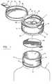
- the dual tamper evident closure 1is intended to be used for sealing a container 3 comprising a neck portion 5 that defines an outlet 7.
- the neck portion 5has an external surface 9 provided with upper and lower connection means 11, 13.
- the upper connection means 11consists of one or more threads made on the external surface 9 of the neck portion 5.
- any other connection means commonly used in the trade for detachably connecting a closure to the neck of a containercould alternatively be used.
- the lower connection means 13 of the neck portion 5consists of an annular bead projecting out from the external surface of the neck portion.
- other connection means used in the trade for the same purposecould alternatively be used.
- the outlet 7 of the neck portion 5 of the containeris closed by a liner 8 that can be glued or welded to the upper edge of the neck portion, and must be pulled out to give access to the container.
- a liner 8is rather conventional, especially for containers in medical field, and needs not be further discussed.
- the closure 1comprises a closure body 15 which comprises a skirt 17 sized and shaped to fit onto the neck portion 5.
- the skirthas a lower edge 19 and comprises an internal surface 21 provided with skirt connection means 23 designed and positioned to cooperate with the upper connection means 11 of the neck portion 5 in order to detachably connect the closure body 15 to the neck portion.
- the skirt connection means 23consists of one or more threads that are opposite to and cooperatively mounted relative to the thread(s) 11 to allow the closure body to be screwed onto the neck.
- the closure body 15also comprises a top surface 25 comprising an opening 27 that is in registry with the outlet 7 of the neck portion 5 when the closure body is connected to this neck portion.
- the shape and configuration of the top surface 25 and the size of the opening 27may of course vary depending on the kind of product stored in the container 3.
- the closure 1also comprises a closure cap 29 which comprises a top wall 31 and a peripheral edge 33.
- the closure cap 29is connected to the closure body 15 by means of a hinge 35 and is sized and shaped to cover the opening 27 of the closure body and thus to close the outlet 7 of the neck portion 5 when folded down in a closed position.
- the closure 1further comprises a tamper evident band 37 consisting of a ring connected by means of frangible bridges 39 to the lower edge 19 of the skirt 17 of the closure body 15.
- the band 37is provided with hooking means 41 designed to cooperate with the lower connection means 13 of the neck portion 5 in order to rigidly retain the closure body 15 onto the neck portion.
- the closure 1the structure of which has just been disclosed, is characterized in that it further comprises a tear tab 43 integrally projecting from the peripheral edge of the closure cap in a position that is opposite to the hinge 35.
- the tab 43has an upper end that is connected by a frangible bridge 45 to the peripheral edge 33 of the closure cap 29. It also has a lower end 47 that is devised to be rigidly connected to the tamper evident band 37.
- the tab 43is sized so that its lower end 49 be connectable to the external surface of the tamper evident band 37.
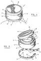
- the tear tabcan be folded down as shown in Figure 2 and then attached to the tamper-evident band 37 as shown in Figure 3. With the tear tab in such an attached position, the tamper evident band 37 assumes two separate functions:
- the closure 1may be removed from the container 3 in order to facilitate removal of the liner 8 closing the outlet of the same.
- the liner 8may be fully removed only after the tear tab 43 and the tamper evident band 37 have been pulled out and the closure body 15 and the closure cap 29 have been unscrewed from the neck portion 5.
- the ring forming said band 37is preferably provided with a frangible portion 51 (see Figures 1 and 5) that allows the ring 37 to be easily cut and then tom away for the skirt 17 when one pulls on the tear tab 49 after the upper end of the tear tab has been torn away from the closure cap 29 (see the arrow in Figures 4 and 5).
- the tear tab 43as long as it remains connected to the closure cap 29, warrants that the closure cap 29 has not been lifted up and thus the container 3 has not been opened.
- the closure 1is made of one single piece of plastic material by molding.
- the plastic materialis preferably polypropylene or other suitable material.
- the lower end 49 of the tear tab 43is connected to the tamper evident band 39 by ultrasonic welding.
- other means for connecting the lower end 49 of the tear tab 43 to the tamper evident band 39could be used.
- the tear tab 43could be integral to the tamper evident band 37 and welded to the cap 29. This would probably be less efficient than the preferred embodiment illustrated in the drawings since additional frangible lines or bridges would be required, but such would work in the same way.
- the basic structure of the skirt and capcould be modified depending on the kind of container the closure would fit, and the kind of product contained in the container.
Landscapes
- Engineering & Computer Science (AREA)
- Mechanical Engineering (AREA)
- Closures For Containers (AREA)
- Filters For Electric Vacuum Cleaners (AREA)
- Seal Device For Vehicle (AREA)
- Pharmaceuticals Containing Other Organic And Inorganic Compounds (AREA)
Abstract
Description
- it warrants, as long as it remains attached to the lower edge of the body skirt, that the closure has not been removed from the neck portion; and
- it warrants, as long as the tear tab remains attached to the cap and to it, thatthe cap has not been opened.
- it warrants, as long as it remains attached to the
lower edge 19 of theskirt 17,that theclosure 1 has not been removed from theneck portion 5; and - it warrants, as long as the
tear tab 43 remains attached to it, that the cap hasnot been opened.
Claims (7)
- A dual tamper evident closure (1) for sealing a container (3) comprisinga neck portion (5) that defines an outlet (7) and has an external surface (9) providedwith upper and lower connection means (11,13), said closure comprising :whereby, in use, the tear tab (43), as long as it remains connected to the closurecap (29), warrants that the closure cap has not been lifted up and thus the container (3)has not been opened.a) a closure body (15)comprising:a skirt (17) sized and shaped to fit onto the neck portion (5), saidskirt having a lower edge (19) and comprising an internal surface (21)provided with skirt connection means (23) designed and positioned tocooperate with the upper connection means (11) of the neck portion inorder to detachably connect the closure body (15) to the neck portion(5); anda top surface (25) comprising an opening (27) that is in registrywith the outlet of the neck portion when the closure body is connectedto said neck portion,b) a closure cap (29) comprising a top wall (31) and a peripheral edge (33),said closure cap being connected to the closure body (15) by means of a hinge (35) andbeing sized and shaped to cover the opening (27) of said dosure body and thus to closethe outlet (7) of the neck portion (5) when folded down in a closed position; andc) a tamper-evident band (37) comprising a ring connected by means offrangible bridges (39) to the lower edge (19) of the skirt (17) of the closure body, saidband (37) being provided with hooking means (41) designed to cooperate with the lowerconnection means (13) of the neck portion (5) in order to rigidly retain the closure bodyonto said neck portion;
characterized in that said closure further comprises:d) either a tear tab (43) integrally projecting from the peripheral edge of theclosure cap in a position that is opposite to the hinge (35), said tear tab having an upperend that is connected by a frangible bridge (45) to the peripheral edge (33) of theclosure cap (29) and a lower end (47) that is rigidly connected to the tamper-evidentband (37), or a tear tab (43) integrally formed with the tamper evident band (37) and welded to the cap (29), - A dual tamper evident closure as claimed in claim 1,characterized inthat said closure (1) is made of one single piece of plastic material.
- A dual tamper evident closure as claimed in claim 2,characterized inthat said plastic material is polypropylene.
- A dual tamper evident closure as claimed in claim 2 or 3,characterizedin that the lower end (47) of the tear tab (43) is connected to the tamper evident band(37) by ultrasonic welding.
- Combination of a container and a dual tamper evident closure as claimed in any one of claims 1 to 4,characterized in that:the lower connection means (13) of the neck portion (5) consists of an annularbead projecting out from the external surface of the neck portion; andthe ring of the tamper evident band (37) comprises a frangible portion (51) thatallows the ring (37) to be easily cut and then to be torn away from the skirt (17) whenone pulls on the tear tab (49) after the upper end of said tear tab has been torn awayfrom the closure cap (29).
- Combination of a container and a dual tamper evident closure as claimed in any one of claims 1 to 5,characterized in that the upper connection means (11) of the neck portion (5) and theskirt connection means (23) of the closure body (15) consist of opposite threads madein the external surface of the neck portion (5) and in the internal surface of the skirt (17),respectively.
- Combination of a container and a dual tamper evident closure as claimed in any one of claims 1 to 6,characterized in that the outlet (7) of the neck portion (5) of the container is closed bya liner (8) that is pulled out to give access to the container after the tear tab (43) and thetamper evident band (37) have been pulled out and the closure body and the closurecap (29) have been unscrewed from the neck portion (5).
Applications Claiming Priority (3)
| Application Number | Priority Date | Filing Date | Title |
|---|---|---|---|
| CA002275012ACA2275012C (en) | 1999-06-15 | 1999-06-15 | Dual tamper evident closure |
| CA2275012 | 1999-06-15 | ||
| PCT/CA2000/000682WO2000076875A1 (en) | 1999-06-15 | 2000-06-06 | Dual tamper evident closure |
Publications (2)
| Publication Number | Publication Date |
|---|---|
| EP1105319A1 EP1105319A1 (en) | 2001-06-13 |
| EP1105319B1true EP1105319B1 (en) | 2004-09-08 |
Family
ID=4163644
Family Applications (1)
| Application Number | Title | Priority Date | Filing Date |
|---|---|---|---|
| EP00938388AExpired - LifetimeEP1105319B1 (en) | 1999-06-15 | 2000-06-06 | Dual tamper evident closure |
Country Status (9)
| Country | Link |
|---|---|
| EP (1) | EP1105319B1 (en) |
| JP (1) | JP2003502223A (en) |
| CN (1) | CN1304374A (en) |
| AT (1) | ATE275507T1 (en) |
| AU (1) | AU5380100A (en) |
| BR (1) | BR0006188A (en) |
| CA (1) | CA2275012C (en) |
| DE (1) | DE60013543T2 (en) |
| WO (1) | WO2000076875A1 (en) |
Families Citing this family (29)
| Publication number | Priority date | Publication date | Assignee | Title |
|---|---|---|---|---|
| US6550626B1 (en) | 2000-10-03 | 2003-04-22 | Seaquist Closures Foreign, Inc. | Closure lid and resealable closure system with tamper-evident features |
| US7281638B2 (en) | 2001-07-24 | 2007-10-16 | Obrist Closures Switzerland Gmbh | Snap-hinge closure with tamper-evident lid and method of making |
| FR2842177B1 (en)* | 2002-07-12 | 2004-12-03 | Bericap | CAP WITH AN IMPERDABLE AND CLEARLY VISIBLE INDICATOR LAMP |
| RU2295483C2 (en)* | 2002-07-12 | 2007-03-20 | Берикап | Sealing device with hinge-fastened cap molded in closed position |
| US6848603B2 (en) | 2002-07-17 | 2005-02-01 | Crown Cork & Seal Technologies Corporation | Closure having improved tamper evident features |
| FR2883261B1 (en)* | 2005-03-16 | 2008-10-10 | Qualipac Soc Par Actions Simpl | ARTICULATED LID CAP AND SAFETY TAB |
| NZ541605A (en)* | 2005-08-01 | 2007-10-26 | Alto Packaging Ltd | Screw closure |
| FR2909975B1 (en) | 2006-12-13 | 2009-04-17 | Eskiss Packaging Soc Par Actio | BOTTLE FOR RECEIVING A DETERMINED DOSE OF A LIQUID |
| WO2010065998A1 (en)* | 2008-12-10 | 2010-06-17 | Raymond John Baker | Secure closure |
| CN201712948U (en)* | 2010-06-18 | 2011-01-19 | 彭实 | Rotary quantifying device |
| CN102582946B (en)* | 2011-01-14 | 2014-09-24 | 林相伍 | Cover used for container |
| AU2012100441B4 (en)* | 2012-04-20 | 2012-11-29 | Etherington, Elizabeth | Improved drink bottle cap |
| WO2015027182A1 (en)* | 2013-08-22 | 2015-02-26 | Cequent Consumer Products, Inc. | Point of sale packaging |
| USD747201S1 (en) | 2013-09-18 | 2016-01-12 | Bericap | Closure |
| CN103538779B (en)* | 2013-10-15 | 2016-03-09 | 李红彪 | A kind of enclosuring structure of packing container |
| FR3015442B1 (en) | 2013-12-24 | 2016-02-05 | Bericap | ARTICULATED CLAMPING DEVICE WITH FIRST OPENING INDICATOR |
| CA2939346C (en) | 2014-02-13 | 2019-08-13 | Obrist Closures Switzerland Gmbh | A tamper-evident closure |
| WO2015128091A1 (en)* | 2014-02-28 | 2015-09-03 | Ferrari, Silvia | Reclosable stopper revealing a first opening |
| PL408833A1 (en) | 2014-07-11 | 2016-01-18 | Zakład Przetwórstwa Tworzyw Sztucznych Witoplast Spółka Jawna | Top piece for packaging, preferably the packaging of cosmetic products |
| USD833278S1 (en) | 2014-09-03 | 2018-11-13 | Bericap | Closure for a container |
| AU367126S (en) | 2015-06-01 | 2016-02-15 | Obrist Closures Switzerland | Bottle neck finish |
| CN105059708B (en)* | 2015-08-04 | 2017-10-03 | 泉州华硕实业有限公司 | A kind of anti-theft bottle cap |
| CN105566389B (en)* | 2016-01-29 | 2017-12-29 | 湖南大学 | [base of 2 (1H) quinolinone 3] application of naphthalene AminomethylphosphoniAcid Acid ester as cancer therapy drug |
| CN105902320A (en)* | 2016-06-03 | 2016-08-31 | 宁波和平鸽口腔医疗器材有限公司 | High-speed turbine dental handpiece suitable for single-use with safety |
| FR3052756B1 (en)* | 2016-06-15 | 2020-08-14 | Albea Services | SERVICE CAPSULE WITH DETACHABLE TAB |
| CN108996006A (en)* | 2016-06-24 | 2018-12-14 | 佛山市海盈食品有限公司 | Bottle cap applied to flexible package punch |
| EP4014810B1 (en) | 2016-07-20 | 2024-06-12 | Blix Ltd. | Single-use food preparation container assembly, system and method |
| CN113998311B (en) | 2017-07-18 | 2024-03-15 | 布利克斯有限公司 | Container, container content processor, container content processing system and method |
| NL2023251B1 (en) | 2019-06-03 | 2020-12-11 | Weener Plastics Group B V | Closure with bonded tamper evidence |
Family Cites Families (9)
| Publication number | Priority date | Publication date | Assignee | Title |
|---|---|---|---|---|
| FR1595945A (en)* | 1968-10-19 | 1970-06-15 | ||
| DE2155664A1 (en)* | 1970-11-13 | 1972-06-29 | Captocap Ltd., Vaduz | Closure |
| US4658976A (en) | 1983-04-15 | 1987-04-21 | Aluminum Company Of America | Lined plastic closure |
| US4487324A (en) | 1984-02-08 | 1984-12-11 | Seaquist Closures | Tamper-evident dispensing closure |
| FI76985C (en)* | 1986-07-07 | 1989-01-10 | Yhtyneet Paperitehtaat Oy | Lid, stopper or equivalent provided with seal and procedure for the ss manufacture. |
| IT1224357B (en) | 1988-04-13 | 1990-10-04 | Bormioli Metalplast Spa | ONE-PIECE CAPSULE WITH DEFORMABLE INVIOLABILITY CLAMP |
| US5147054A (en) | 1991-05-20 | 1992-09-15 | Pehr Harold T | Tamper-proof container |
| CH683417A5 (en) | 1991-06-21 | 1994-03-15 | Createchnic Ag | Snap hinge closure with tamper-evident band. |
| JP3471984B2 (en)* | 1995-06-09 | 2003-12-02 | 株式会社ミツカングループ本社 | Removable cap |
- 1999
- 1999-06-15CACA002275012Apatent/CA2275012C/ennot_activeExpired - Fee Related
- 2000
- 2000-06-06ATAT00938388Tpatent/ATE275507T1/ennot_activeIP Right Cessation
- 2000-06-06EPEP00938388Apatent/EP1105319B1/ennot_activeExpired - Lifetime
- 2000-06-06BRBR0006188-3Apatent/BR0006188A/ennot_activeApplication Discontinuation
- 2000-06-06JPJP2001503351Apatent/JP2003502223A/ennot_activeWithdrawn
- 2000-06-06CNCN00800807Apatent/CN1304374A/enactivePending
- 2000-06-06AUAU53801/00Apatent/AU5380100A/ennot_activeAbandoned
- 2000-06-06WOPCT/CA2000/000682patent/WO2000076875A1/enactiveIP Right Grant
- 2000-06-06DEDE60013543Tpatent/DE60013543T2/ennot_activeExpired - Lifetime
Also Published As
| Publication number | Publication date |
|---|---|
| ATE275507T1 (en) | 2004-09-15 |
| EP1105319A1 (en) | 2001-06-13 |
| WO2000076875A1 (en) | 2000-12-21 |
| CA2275012C (en) | 2006-06-13 |
| AU5380100A (en) | 2001-01-02 |
| BR0006188A (en) | 2001-04-17 |
| JP2003502223A (en) | 2003-01-21 |
| DE60013543D1 (en) | 2004-10-14 |
| CN1304374A (en) | 2001-07-18 |
| CA2275012A1 (en) | 2000-12-15 |
| DE60013543T2 (en) | 2005-09-29 |
Similar Documents
| Publication | Publication Date | Title |
|---|---|---|
| US6116441A (en) | Dual tamper evident closure | |
| EP1105319B1 (en) | Dual tamper evident closure | |
| US5755360A (en) | Multi-material, multi-shot, injection molded dispensing closure having a removable seal | |
| CN113015683A (en) | Tethered closure with stable opening angle | |
| EP1086024B1 (en) | Closure with dual hinge means | |
| US6631820B2 (en) | Tamper-evident dispensing closure with partial breakaway cover | |
| US5855288A (en) | Resealable closure | |
| US6347716B1 (en) | Flip top cap with tamper evident flap | |
| AU593266B2 (en) | Plastic closure with safety band | |
| US6460712B2 (en) | One-piece tamper-evident closure system with a resealable, hinged lid | |
| EP2213584B1 (en) | A tamper-evident closure | |
| US5207783A (en) | Safety closures for containers | |
| US5697509A (en) | Hinged tamper-evidencing closure | |
| CA2247813A1 (en) | Flip top cap with tamper evident flap | |
| WO2003010061A2 (en) | Hinged tamper evident closure | |
| WO2014122314A2 (en) | Improvements in or relating to closures | |
| US5405031A (en) | Closure for a medicine bottle | |
| US6237818B1 (en) | Tamper evident pouring spout | |
| JP2003040299A (en) | Cap with pouring out cylinder | |
| JP3241460B2 (en) | cap | |
| JPH0245364A (en) | Cap with hinge | |
| JP2004175436A (en) | Hinge cap having tamper-evident property | |
| JP2001287761A (en) | Resin cap excellent in fractional disposal properties | |
| GB2316399A (en) | Tamper evident container |
Legal Events
| Date | Code | Title | Description |
|---|---|---|---|
| PUAI | Public reference made under article 153(3) epc to a published international application that has entered the european phase | Free format text:ORIGINAL CODE: 0009012 | |
| 17P | Request for examination filed | Effective date:20010307 | |
| AK | Designated contracting states | Kind code of ref document:A1 Designated state(s):AT BE CH CY DE DK ES FI FR GB GR IE IT LI LU MC NL PT SE | |
| AX | Request for extension of the european patent | Free format text:AL;LT;LV;MK;RO;SI | |
| GRAP | Despatch of communication of intention to grant a patent | Free format text:ORIGINAL CODE: EPIDOSNIGR1 | |
| GRAS | Grant fee paid | Free format text:ORIGINAL CODE: EPIDOSNIGR3 | |
| GRAA | (expected) grant | Free format text:ORIGINAL CODE: 0009210 | |
| AK | Designated contracting states | Kind code of ref document:B1 Designated state(s):AT BE CH CY DE DK ES FI FR GB GR IE IT LI LU MC NL PT SE | |
| PG25 | Lapsed in a contracting state [announced via postgrant information from national office to epo] | Ref country code:IT Free format text:LAPSE BECAUSE OF FAILURE TO SUBMIT A TRANSLATION OF THE DESCRIPTION OR TO PAY THE FEE WITHIN THE PRESCRIBED TIME-LIMIT;WARNING: LAPSES OF ITALIAN PATENTS WITH EFFECTIVE DATE BEFORE 2007 MAY HAVE OCCURRED AT ANY TIME BEFORE 2007. THE CORRECT EFFECTIVE DATE MAY BE DIFFERENT FROM THE ONE RECORDED. Effective date:20040908 Ref country code:CH Free format text:LAPSE BECAUSE OF FAILURE TO SUBMIT A TRANSLATION OF THE DESCRIPTION OR TO PAY THE FEE WITHIN THE PRESCRIBED TIME-LIMIT Effective date:20040908 Ref country code:FI Free format text:LAPSE BECAUSE OF FAILURE TO SUBMIT A TRANSLATION OF THE DESCRIPTION OR TO PAY THE FEE WITHIN THE PRESCRIBED TIME-LIMIT Effective date:20040908 Ref country code:LI Free format text:LAPSE BECAUSE OF FAILURE TO SUBMIT A TRANSLATION OF THE DESCRIPTION OR TO PAY THE FEE WITHIN THE PRESCRIBED TIME-LIMIT Effective date:20040908 Ref country code:AT Free format text:LAPSE BECAUSE OF FAILURE TO SUBMIT A TRANSLATION OF THE DESCRIPTION OR TO PAY THE FEE WITHIN THE PRESCRIBED TIME-LIMIT Effective date:20040908 Ref country code:BE Free format text:LAPSE BECAUSE OF FAILURE TO SUBMIT A TRANSLATION OF THE DESCRIPTION OR TO PAY THE FEE WITHIN THE PRESCRIBED TIME-LIMIT Effective date:20040908 Ref country code:NL Free format text:LAPSE BECAUSE OF FAILURE TO SUBMIT A TRANSLATION OF THE DESCRIPTION OR TO PAY THE FEE WITHIN THE PRESCRIBED TIME-LIMIT Effective date:20040908 | |
| REG | Reference to a national code | Ref country code:GB Ref legal event code:FG4D | |
| REG | Reference to a national code | Ref country code:CH Ref legal event code:EP | |
| REG | Reference to a national code | Ref country code:IE Ref legal event code:FG4D | |
| REF | Corresponds to: | Ref document number:60013543 Country of ref document:DE Date of ref document:20041014 Kind code of ref document:P | |
| PG25 | Lapsed in a contracting state [announced via postgrant information from national office to epo] | Ref country code:SE Free format text:LAPSE BECAUSE OF FAILURE TO SUBMIT A TRANSLATION OF THE DESCRIPTION OR TO PAY THE FEE WITHIN THE PRESCRIBED TIME-LIMIT Effective date:20041208 Ref country code:GR Free format text:LAPSE BECAUSE OF FAILURE TO SUBMIT A TRANSLATION OF THE DESCRIPTION OR TO PAY THE FEE WITHIN THE PRESCRIBED TIME-LIMIT Effective date:20041208 Ref country code:DK Free format text:LAPSE BECAUSE OF FAILURE TO SUBMIT A TRANSLATION OF THE DESCRIPTION OR TO PAY THE FEE WITHIN THE PRESCRIBED TIME-LIMIT Effective date:20041208 | |
| PG25 | Lapsed in a contracting state [announced via postgrant information from national office to epo] | Ref country code:ES Free format text:LAPSE BECAUSE OF FAILURE TO SUBMIT A TRANSLATION OF THE DESCRIPTION OR TO PAY THE FEE WITHIN THE PRESCRIBED TIME-LIMIT Effective date:20041219 | |
| LTIE | Lt: invalidation of european patent or patent extension | Effective date:20040908 | |
| NLV1 | Nl: lapsed or annulled due to failure to fulfill the requirements of art. 29p and 29m of the patents act | ||
| REG | Reference to a national code | Ref country code:CH Ref legal event code:PL | |
| PG25 | Lapsed in a contracting state [announced via postgrant information from national office to epo] | Ref country code:IE Free format text:LAPSE BECAUSE OF NON-PAYMENT OF DUE FEES Effective date:20050606 Ref country code:CY Free format text:LAPSE BECAUSE OF FAILURE TO SUBMIT A TRANSLATION OF THE DESCRIPTION OR TO PAY THE FEE WITHIN THE PRESCRIBED TIME-LIMIT Effective date:20050606 Ref country code:LU Free format text:LAPSE BECAUSE OF NON-PAYMENT OF DUE FEES Effective date:20050606 | |
| PG25 | Lapsed in a contracting state [announced via postgrant information from national office to epo] | Ref country code:MC Free format text:LAPSE BECAUSE OF NON-PAYMENT OF DUE FEES Effective date:20050630 | |
| PLBE | No opposition filed within time limit | Free format text:ORIGINAL CODE: 0009261 | |
| STAA | Information on the status of an ep patent application or granted ep patent | Free format text:STATUS: NO OPPOSITION FILED WITHIN TIME LIMIT | |
| ET | Fr: translation filed | ||
| 26N | No opposition filed | Effective date:20050609 | |
| REG | Reference to a national code | Ref country code:IE Ref legal event code:MM4A | |
| PG25 | Lapsed in a contracting state [announced via postgrant information from national office to epo] | Ref country code:PT Free format text:LAPSE BECAUSE OF NON-PAYMENT OF DUE FEES Effective date:20050208 | |
| PGFP | Annual fee paid to national office [announced via postgrant information from national office to epo] | Ref country code:DE Payment date:20120627 Year of fee payment:13 | |
| PGFP | Annual fee paid to national office [announced via postgrant information from national office to epo] | Ref country code:GB Payment date:20120625 Year of fee payment:13 Ref country code:FR Payment date:20120705 Year of fee payment:13 | |
| GBPC | Gb: european patent ceased through non-payment of renewal fee | Effective date:20130606 | |
| REG | Reference to a national code | Ref country code:DE Ref legal event code:R119 Ref document number:60013543 Country of ref document:DE Effective date:20140101 | |
| REG | Reference to a national code | Ref country code:FR Ref legal event code:ST Effective date:20140228 | |
| PG25 | Lapsed in a contracting state [announced via postgrant information from national office to epo] | Ref country code:GB Free format text:LAPSE BECAUSE OF NON-PAYMENT OF DUE FEES Effective date:20130606 Ref country code:DE Free format text:LAPSE BECAUSE OF NON-PAYMENT OF DUE FEES Effective date:20140101 | |
| PG25 | Lapsed in a contracting state [announced via postgrant information from national office to epo] | Ref country code:FR Free format text:LAPSE BECAUSE OF NON-PAYMENT OF DUE FEES Effective date:20130701 |