EP1105181B1 - Preformed wire guide - Google Patents
Preformed wire guideDownload PDFInfo
- Publication number
- EP1105181B1 EP1105181B1EP99942312AEP99942312AEP1105181B1EP 1105181 B1EP1105181 B1EP 1105181B1EP 99942312 AEP99942312 AEP 99942312AEP 99942312 AEP99942312 AEP 99942312AEP 1105181 B1EP1105181 B1EP 1105181B1
- Authority
- EP
- European Patent Office
- Prior art keywords
- wire guide
- mandril
- wire
- vessel
- preformed bend
- Prior art date
- Legal status (The legal status is an assumption and is not a legal conclusion. Google has not performed a legal analysis and makes no representation as to the accuracy of the status listed.)
- Expired - Lifetime
Links
- 229910001000nickel titaniumInorganic materials0.000claimsdescription25
- 239000000463materialSubstances0.000claimsdescription19
- 229910000734martensiteInorganic materials0.000claimsdescription16
- 238000000576coating methodMethods0.000claimsdescription11
- 238000005482strain hardeningMethods0.000claimsdescription9
- 239000011248coating agentSubstances0.000claimsdescription7
- 229920000642polymerPolymers0.000claimsdescription7
- 238000004873anchoringMethods0.000claimsdescription3
- 238000000034methodMethods0.000description23
- HLXZNVUGXRDIFK-UHFFFAOYSA-Nnickel titaniumChemical compound[Ti].[Ti].[Ti].[Ti].[Ti].[Ti].[Ti].[Ti].[Ti].[Ti].[Ti].[Ni].[Ni].[Ni].[Ni].[Ni].[Ni].[Ni].[Ni].[Ni].[Ni].[Ni].[Ni].[Ni].[Ni]HLXZNVUGXRDIFK-UHFFFAOYSA-N0.000description21
- 210000002254renal arteryAnatomy0.000description12
- RVTZCBVAJQQJTK-UHFFFAOYSA-Noxygen(2-);zirconium(4+)Chemical compound[O-2].[O-2].[Zr+4]RVTZCBVAJQQJTK-UHFFFAOYSA-N0.000description9
- 230000008901benefitEffects0.000description7
- 229910045601alloyInorganic materials0.000description5
- 239000000956alloySubstances0.000description5
- 238000000137annealingMethods0.000description5
- 210000000709aortaAnatomy0.000description5
- 208000014674injuryDiseases0.000description5
- 229920001343polytetrafluoroethylenePolymers0.000description5
- 239000004810polytetrafluoroethyleneSubstances0.000description5
- 210000003484anatomyAnatomy0.000description4
- 238000002399angioplastyMethods0.000description4
- 238000013459approachMethods0.000description4
- 230000003902lesionEffects0.000description4
- 230000008569processEffects0.000description4
- 239000007787solidSubstances0.000description4
- 239000010935stainless steelSubstances0.000description4
- 229910001220stainless steelInorganic materials0.000description4
- 230000008733traumaEffects0.000description4
- 208000007536ThrombosisDiseases0.000description3
- HZEWFHLRYVTOIW-UHFFFAOYSA-N[Ti].[Ni]Chemical compound[Ti].[Ni]HZEWFHLRYVTOIW-UHFFFAOYSA-N0.000description3
- 229910052751metalInorganic materials0.000description3
- 239000002184metalSubstances0.000description3
- 210000002796renal veinAnatomy0.000description3
- 229910000679solderInorganic materials0.000description3
- XEEYBQQBJWHFJM-UHFFFAOYSA-NIronChemical compound[Fe]XEEYBQQBJWHFJM-UHFFFAOYSA-N0.000description2
- PXHVJJICTQNCMI-UHFFFAOYSA-NNickelChemical compound[Ni]PXHVJJICTQNCMI-UHFFFAOYSA-N0.000description2
- 208000031481Pathologic ConstrictionDiseases0.000description2
- -1PolytetrafluoroethylenePolymers0.000description2
- 208000004531Renal Artery ObstructionDiseases0.000description2
- 210000001367arteryAnatomy0.000description2
- 229910001566austeniteInorganic materials0.000description2
- 230000006378damageEffects0.000description2
- 238000004519manufacturing processMethods0.000description2
- 230000036262stenosisEffects0.000description2
- 208000037804stenosisDiseases0.000description2
- 230000001954sterilising effectEffects0.000description2
- 238000004659sterilization and disinfectionMethods0.000description2
- 238000012546transferMethods0.000description2
- 230000009466transformationEffects0.000description2
- 230000007704transitionEffects0.000description2
- VYZAMTAEIAYCRO-UHFFFAOYSA-NChromiumChemical compound[Cr]VYZAMTAEIAYCRO-UHFFFAOYSA-N0.000description1
- 229910000881Cu alloyInorganic materials0.000description1
- 229910017535Cu-Al-NiInorganic materials0.000description1
- 208000005189EmbolismDiseases0.000description1
- 206010019280Heart failuresDiseases0.000description1
- 208000001647Renal InsufficiencyDiseases0.000description1
- RTAQQCXQSZGOHL-UHFFFAOYSA-NTitaniumChemical compound[Ti]RTAQQCXQSZGOHL-UHFFFAOYSA-N0.000description1
- 208000027418Wounds and injuryDiseases0.000description1
- 230000001154acute effectEffects0.000description1
- 208000037849arterial hypertensionDiseases0.000description1
- 238000007630basic procedureMethods0.000description1
- 238000005452bendingMethods0.000description1
- 210000004204blood vesselAnatomy0.000description1
- 230000036760body temperatureEffects0.000description1
- 230000008859changeEffects0.000description1
- 229910052804chromiumInorganic materials0.000description1
- 239000011651chromiumSubstances0.000description1
- 238000010622cold drawingMethods0.000description1
- 230000000295complement effectEffects0.000description1
- 238000007887coronary angioplastyMethods0.000description1
- 208000029078coronary artery diseaseDiseases0.000description1
- 210000004351coronary vesselAnatomy0.000description1
- 239000013078crystalSubstances0.000description1
- 230000001419dependent effectEffects0.000description1
- 230000003467diminishing effectEffects0.000description1
- 230000009977dual effectEffects0.000description1
- 210000001105femoral arteryAnatomy0.000description1
- 238000002594fluoroscopyMethods0.000description1
- 238000009472formulationMethods0.000description1
- PCHJSUWPFVWCPO-UHFFFAOYSA-NgoldChemical compound[Au]PCHJSUWPFVWCPO-UHFFFAOYSA-N0.000description1
- 229910052737goldInorganic materials0.000description1
- 239000010931goldSubstances0.000description1
- 238000003384imaging methodMethods0.000description1
- 229910052742ironInorganic materials0.000description1
- 210000003734kidneyAnatomy0.000description1
- 201000006370kidney failureDiseases0.000description1
- 150000002739metalsChemical class0.000description1
- 239000000203mixtureSubstances0.000description1
- 238000012986modificationMethods0.000description1
- 230000004048modificationEffects0.000description1
- 229910052759nickelInorganic materials0.000description1
- 230000010363phase shiftEffects0.000description1
- 230000000704physical effectEffects0.000description1
- 239000004033plasticSubstances0.000description1
- BASFCYQUMIYNBI-UHFFFAOYSA-NplatinumChemical compound[Pt]BASFCYQUMIYNBI-UHFFFAOYSA-N0.000description1
- 239000002243precursorSubstances0.000description1
- 230000009467reductionEffects0.000description1
- 210000005227renal systemAnatomy0.000description1
- 238000005476solderingMethods0.000description1
- 238000010561standard procedureMethods0.000description1
- 230000002966stenotic effectEffects0.000description1
- 238000004381surface treatmentMethods0.000description1
- 238000001356surgical procedureMethods0.000description1
- 229910052715tantalumInorganic materials0.000description1
- GUVRBAGPIYLISA-UHFFFAOYSA-Ntantalum atomChemical compound[Ta]GUVRBAGPIYLISA-UHFFFAOYSA-N0.000description1
- 239000010936titaniumSubstances0.000description1
- 229910052719titaniumInorganic materials0.000description1
- 230000001052transient effectEffects0.000description1
- WFKWXMTUELFFGS-UHFFFAOYSA-NtungstenChemical compound[W]WFKWXMTUELFFGS-UHFFFAOYSA-N0.000description1
- 229910052721tungstenInorganic materials0.000description1
- 239000010937tungstenSubstances0.000description1
- 229910052720vanadiumInorganic materials0.000description1
- LEONUFNNVUYDNQ-UHFFFAOYSA-Nvanadium atomChemical compound[V]LEONUFNNVUYDNQ-UHFFFAOYSA-N0.000description1
- 210000005166vasculatureAnatomy0.000description1
Images


Classifications
- A—HUMAN NECESSITIES
- A61—MEDICAL OR VETERINARY SCIENCE; HYGIENE
- A61M—DEVICES FOR INTRODUCING MEDIA INTO, OR ONTO, THE BODY; DEVICES FOR TRANSDUCING BODY MEDIA OR FOR TAKING MEDIA FROM THE BODY; DEVICES FOR PRODUCING OR ENDING SLEEP OR STUPOR
- A61M25/00—Catheters; Hollow probes
- A61M25/01—Introducing, guiding, advancing, emplacing or holding catheters
- A61M25/09—Guide wires
- A61M2025/09175—Guide wires having specific characteristics at the distal tip
Definitions
- This inventionrelates generally to medical devices and, in particular, to a wire guide.
- Balloon angioplastya medical procedure by which an occluded or narrowed blood vessel is dilated and reopened using an inflatable balloon mounted on a catheter, was pioneered by Andreas Greuntzig in the 1970's.
- the coronary version of this new procedurePercutaneous Transluminal Coronary Angioplasty (PTCA)
- PTCAPercutaneous Transluminal Coronary Angioplasty
- angioplastyhas become a standard approach for treatment of renal artery stenoses.
- PTRAPercutaneous Transluminal Renal Angioplasty
- the basic angioplasty procedureusually involves percutaneously introducing a guiding catheter through an introducer sheath to the target site and then engaging the ostium of the vessel.
- a wire guideis fed through the guiding catheter and ostium where it is placed across the lesion in the vessel.
- a balloon catheteris introduced over the wire guide and positioned at the lesion to dilate the vessel.
- a stentis also placed following balloon dilatation to prevent restenoses of the lesion.
- One procedure for placing the balloon catheter at the treatment siteis known as the "Push-Pull" Technique whereby the physician advances the balloon catheter through the guiding catheter ("push") while applying slight forward pressure to the latter.
- an assistantholds the proximal end of the wire guide, providing gentle traction ("pull"). Care must be taken during the advancement of the catheter to avoid dislodging the wire guide from the treatment site. This is especially of concern during a renal procedure due to the relatively short length of the renal artery and the acute angle of the artery relative to the aorta.
- US-A-5295493is disclosed in US-A-5295493 to be of solid flexible wire such as of stainless steel, that is formed to have a preformed shape conforming when unstressed to the general anatomical shape of the particular segment of a vessel that has a stenosis to be removed in an atherectomy.
- Another prior art guidewireis disclosed in US-A-5238004, which is used as a basis for the preamble of claim 1.
- At least the distal portionis formed from a precursor of a superelastic alloy (e.g., nitinol) by cold drawing;
- the guidewirehas a solid core with a tapered elongate distal tip portion that is elastic and deformable, and a highly flexible spring coil wire is secured about the distal tip portion, such that the distal tip portion can be manually shaped into a curvature to complement the curvature of the lumen of the patient.
- the wire guidehas a mandril with a flexible tip portion that is atraumatic to the vessel as the wire guide is advanced.
- the flexible tip portionhas a distal tip.
- a proximal portionincludes a preformed bend approximating the takeoff angle of a vessel, for example, a renal artery relative to the aorta from which it branches.
- a related benefit of the present inventionis lowering the risk of displacing thrombus that often forms just inside the ostium, especially in the presence of a stenotic lesion.
- a straight wirewould receive much of the force at the turn into the ostium created by the advancing catheter and potentially transfer much of that force to the wall of the vessel.
- Nitinolcan be permanently shaped by annealing with extreme heat, or by cold-working which involves overstressing the wire. To produce a more rigid bend segment for protecting the vessel, cold working the nitinol mandril is preferred over the annealed embodiment which exhibits less resistance to the tracking forces of the catheter.
- the second major benefit of having an anatomically shaped preformed bendis providing a portion of the wire guide to serve as an anchor to maintain the device within the vessel during advancement of a catheter over the wire.
- a straight wire guidewould be much more likely to become dislodged during the course of tracking the catheter to the treatment site.
- the flexible tip portionincludes a spring coil wire that is attached over a solid wire mandril.
- the transition between the highly-flexible atraumatic tip and the stiffer mandrilis relatively abrupt, compared to typical wire guides, due to the short available length of vessel in which the anchoring portion of the mandril can reside and the need for that mandril to be of sufficient stiffness to maintain a proper anchor.
- a bend having a preferred range of 30° to 150° formed in the mandril wireallows the wire guide to more easily enter the ostium of the renal artery or vein, depending on the particular anatomy of the patient, and whether a superior or inferior approach is used.
- a more preferred range of bend anglesis 45° to 135°, with the most preferred range being 60° to 120°.
- the solid mandril wireis of sufficient stiffness to retain the anatomical preformed bend and allow the wire guide to remain anchored in the vessel while a catheter is being fed over the wire.
- the mandril wireis made of a superelastic material such as a nickel-titanium (Ni-Ti) alloy (commercially available as nitinol).
- Ni-Tinickel-titanium
- the bend in the mandrilis formed by mechanically stressing (cold working) and plastically deforming the wire While in its austenitic state to create at least a partial localized zone of martensite.
- the nitinol wirecan be made relatively thin while still retaining the preformed bend and the requisite stiffness.
- the annealed wire guideis completely in an austenitic state, even in the curved regions.
- the face-centered crystals of the austenitic materialshift to martensite until the stress is removed.
- the bend and straight portions of the annealed wire guidehave very similar flexural properties.
- the cold-worked wire guideis comprised of regions of both austenite and martensite along its length. Consequently, the preformed bend of a cold-worked renal wire guide remains in at least a partial martensitic state and does not exhibit the unusual superelastic phenomenon that occurs during an austenitic to martensitic transformation.
- the flexible tip portion of the preferred embodimenthas a curved shape.
- the "J"-tip of the illustrative embodimentprotects the vessel and delicate tissues as the wire guide is advanced into the renal vein.
- a curved shape tipis more easily deflected and prevents the stiff mandril wire from exerting a dangerous amount of force against the vessel wall.
- the transition from a flexible tip to the stiffer mandrilis achieved by soldering the spring coil tip to the tapered end of the mandril at the point where the taper begins.
- the tapered distal end of the mandrilprovides the overlapping coiled portion with a diminishing degree of stiffness toward its distal end.
- a polymer coatingis added to the mandril of the wire guide for improved lubricity.
- Polytetrafluoroethylene (PTFE)is the preferred material; however, hydrophilic coatings such as SLIP-COATTM (Sterilization Technical Services, Inc., Rush, NY) can be used as an alternative material as well as other lubricious coatings or coating materials.
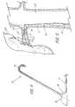
- FIG. 1depicts a side view of an illustrative embodiment of wire guide 10 of the present invention.
- the wire guide 10includes both a mandril 11 and a tip portion 12, preferably a flexible tip portion 12, extending proximally from the distal tip 30 of the wire guide.
- the mandril 11extends the entire length of the wire guide with distal end 25 of the flexible tip portion 12 extending from distal tip 30 of the wire guide to proximal end 26 of the flexible tip portion 12 and to solder joint 13.
- the mandril 11includes a preformed bend 14 that marks the beginning of a distal portion 27 of the wire guide. Angling the distal portion 27 facilitates entry of the wire guide into the ostium of the renal artery.
- the distal portion 27becomes an anchor to help prevent dislodgment of the wire after it has been placed.
- the wire guideis also anatomically shaped for procedures involving the renal vein, however these are far less common.
- the takeoff of the renal artery from the aortavaries in its angle. Therefore, it is contemplated that the wire guide be made available with different bend angles to accommodate the normal variation in patient anatomy.
- An additional factoris that the wire guide can be introduced using either an inferior approach via the femoral artery (preferred) or a superior approach, typically via a brachial access site.
- the wire guide bend anglescan range from 30° to 150°, with a more preferred range of 45° to 135°.
- the distal portion 27 of the first illustrative embodimentis bent at an angle 15 of approximately 60° relative to the longitudinal axis 28 of the wire guide 10.
- a second embodiment depicted in FIG. 4has a preformed bend 14 with an angle 15 of approximately 120°. Together, these two embodiments represent the most common, and therefore, most preferred range of angles for accessing the renal artery.
- a third preferred embodimentis depicted in FIG. 5 whereby the distal portion 27 of the wire guide 10 is formed at a 90° angle.
- the portion of the mandril 11 proximal to the flexible tip portion 12is comprised of a mandril core 18 and a microthin polymer outer coating 19 such as polytetrafluoroethylene (PTFE) as depicted in FIG. 3.
- PTFEpolytetrafluoroethylene
- Alternative coatingsinclude hydrophilic materials such as SLIP-COATTM polymers (Sterilization Technical Services, Inc., Rush, NY) or other polymers that have been surface treated to increase lubricity.
- the mandril core 18includes material having superelastic properties such as the Ni-Ti alloy commercially known and available as nitinol.
- Nitinolis comprised of nearly equal parts of nickel and titanium and can also include small amounts of other metals such as vanadium, chromium, or iron to affect the physical properties of the alloy.
- the preferred nitinol formulation for this applicationhas a martensitic to austenitic transformation temperature below body temperature, and most preferably, below normal room temperature. The remarkable ability of a superelastic alloy to return to its predetermined shape when subjected to stress, makes it an excellent material for this application.
- the plastic deformation that can occur with ordinary metal wires during manipulationcan affect the efficacy of the device.
- superelastic copper alloyssuch as Cu-Al-Ni and Cu-Al-Zi are available as alternative wire guide materials.
- the preferred diameter for the wire guideranges from about .010 to .035 in (0.254 to 0.889 mm) with a diameter of approximately .018 in (0.457 mm). mostly comprised of the nitinol metallic core 18, being generally preferred when using a single diameter wire guide.
- Another embodimentincludes making the mandril 11 larger in diameter, e.g., .023 in (0.584 mm), and attenuating the tip 12 to .018 in (0.457 mm).
- the larger mandrilprovides better positional support for placement in the renal vessel, while attenuation of the distal portion 27 advantageously provides a substantially atraumatic tip.
- the basic procedureinvolves maintaining the device in the desired final shape while subjecting it to extreme heat for a prescribed period of time. Stressing the wire guide under annealing temperatures "locks" the curve in an austenitic state. When the annealed wire guide is deflected, there is a localized, transient shift of the austenitic material to martensite, known as stress-induced martensite (SIM). While annealing represents a viable method of producing the specific bend in the present invention, the preferred method involves cold working the wire guide, i.e., reshaping the wire guide by the application of sufficient mechanical force to permanently shift a portion of the crystalline structure of the nitinol from austenite to martensite within the region of the preformed bend.
- SIMstress-induced martensite
- the stress required to permanently deform the device to the degree requiredis considerable.
- One method of cold working the nitinol wireinvolves using a fixture or forming tool which holds the wire and includes a pin around which the wire is deformed into a much tighter angle than the final angle. The diameter of the pin, the position of wire within the fixture, and the degree of force applied determine the tightness of the resulting bend.
- predetermined wire and fixture parametersit is possible to achieve a predictable angle of bend using such a forming tool to overstress the nitinol wire.
- FIG. 7graphically depicts the generalized stress-strain curves 35 and 36 for similar wires made from cold-worked nitinol and annealed nitinol 35 and 36, respectively.
- stress 37is applied to the cold-worked nitinol wire 35, there is an initial resistance 38 to the increase in strain 39.
- annealed nitinol curve 36exhibits the traditional SIM stress-strain curve whereby following an initial resistance to strain exhibited by portion 41 of the curve, the material enters the stress-induced martensitic phase, depicted by portion 42 of the curve.
- the devicecan continue to deflect (strain) with minimal application of additional stress.
- strainthe stress-strain relationship for the material becomes much more linear.
- Both processesproduce a device with nitinol's superelastic properties, yet the preformed bend of the annealed device becomes highly flexible when subjected to stress and undergoes the phase change
- the stiffer preformed bend of the cold-worked deviceis ideal for the renal wire guide because of its dual function as an anchor into the renal artery and a track over which a catheter is guided. While increased flexibility can be an advantage for certain medical applications, a more flexible annealed wire guide would be more likely to dislodge from the vessel as the PTRA balloon catheter is tracking over the guide.
- the second advantage of cold working the bend of the wire guide of the present inventionis that stock polymer-coated nitinol wire can be used to manufacture the finished device.
- the high temperatures required to produce the annealed wire guidepreclude using the pre-coated wire stock since the polymer coating cannot withstand the temperatures used in the annealing process. This means that virtually any coatings or treatment must be performed by the manufacturer as a final step.
- Cold workingallows a manufacturer the flexibility to purchase pre-coated nitinol wire stock, easily customizing the shape of the stock or existing straight wire guides for a given application, and doing so at a lower cost.
- the flexible tip portion 12 of the wire guide 10provides a distal tip 30 that is atraumatic to the vessel and far less likely to damage delicate tissues during introduction and positioning of the wire guide.
- the flexible tip portion 12comprises a segment of spring coil wire 16 with closely adjacent turns.
- Platinum wireis used to make the distal end of the device highly visible under fluoroscopy.
- Other possible radiopaque materialsinclude gold, tantalum, or tungsten. Radiolucent materials such as stainless steel can also be used.
- the poor imaging disadvantagecan be overcome if a second radiopaque material is used in conjunction with the stainless steel such as at the tip or being interwound with the stainless steel coil.
- a surface treatmentcan also be used to make the coil radiopaque or echogenic.
- the distal tip 30 of the coiled flexible portionterminates in a solder tip that is ground into a rounded shape and then buffed to minimize potential trauma.
- the solder joint 13 that joins the coiled, flexible portion to the mandrilis made through a process that is fully described in U.S. Patent No. 5,242,759 to Hall entitled, "Joint, a Laminate, and a Nickel-Titanium Alloy Member Surface for Bonding to Another Layer of Metal".
- the distal end 25 of the flexible tip portion 12includes a curve 31 to reduce the likelihood of trauma caused from the advancing wire guide.
- the curve 31comprises a hook-shaped tip 29, such as a "J" or "Shepard's crook". Directing the distal tip 30 of flexible portion away from the distal end 25 of the wire guide provides a higher degree of protection against damaging tissue compared to the concentrated force that is potentially exerted by a forward-directed tip, even though the tip is made to flex with contact.
- FIG. 2depicts an alternative atraumatic flexible tip portion 12 that contains a curve 31 of approximately 45° that causes the distal tip 30 to laterally deflect when it encounters resistance.
- FIG. 6depicts an enlarged, partially sectioned side view of the flexible tip portion 12 of the illustrative wire guide 10 of FIG. 1.
- one end portion 20 of the mandril 11includes a tapered distal portion 20 wherein the taper begins at the point 13 at where the coiled, flexible tip portion 12 is soldered to the mandril.
- the tapercontinues to soldered distal tip 30 at the distal end of the mandril.
- the taperis produced by performing a centerless grind of the nitinol core 18, a process which also removes the existing PTFE coating.
- the reduction in diameter of the tapered distal portion 20is gradual across its entire length.
- the overall tapercan be accomplished in a stepped manner with an alternating series of tapered and straight portions.
- the taperboth permits the flexible portion to attach relatively flush to the coated mandril wire such that the outside diameter of the wire guide remains constant across its entire length, and imparts an increasing degree of flexibility to the flexible portion of the wire guide.
- the taper of the mandrilnormally begins prior to the attachment point of the flexible portion.
- the flexible portioncan be soldered to the distal end of the mandril, usually making a standard safety wire necessary so that the flexible portion remains secured to the mandril, the result would be a tip of uniform flexibility that would provide less protection to the patient from the much stiffer advancing mandril wire.
- the coiled wire 16 of the flexible tip portion 12assumes the shape of the shaped tapered distal portion 20 and would otherwise comprise a straight segment at the distal end of the device. Creating a curve 31 such as the "J"-shaped hook 29 at the distal end 25 of the wire guide is accomplished in similar manner as the anatomical preformed bend 14 of the mandril (depicted in FIG. 1).
- the distal tapered portion 20is formed into a curve 31 by overstressing the wire over a forming tool to produce the desired final preformed bend.
- the distal bend 32 in the tapered nitinol portion 20undergoes at least a partial localized phase shift to martensite due to the mechanical stress.
- the distal bend 32 in the tapered portiondiffers in structure from stress-induced martensite produced by the combination of heat and mechanical stress, although the latter technique is also an alternative method of forming the distal bend 32.
- a wire guide that lacks the coiled portionwould represent a viable alternative embodiment.
- the primary requirementis that the distal portion is sufficiently flexible to be atraumatic to tissue, whether by tapering or other structural modifications.
- FIG. 5depicts partially-sectioned view of the wire guide 10 of the present invention placed within the renal anatomy of a patient to illustrate its use.
- the distal portion 27 of the wire guideis anchored within the renal artery 23 which supplies the right kidney 24.
- the preformed bend 14 of mandril portionwhich is at a 90° angle in this particular embodiment, is situated at the ostium 22 where the aorta 33 feeds into the renal artery.
- the flexible tip portion 12 of the wire guidelies distal to the ostium 22 within the renal artery 23 and usually extends to a point proximal to where the renal artery branches to form the interlobar arteries 34.
- the distal portion 27 of the wire guideprovides a firm anchor to resist dislodgment when a PTRA catheter 21 is fed over the wire to dilate a stenosis 17 of the renal artery. This is especially critical as the advancing catheter nears the ostium 22.
Landscapes
- Health & Medical Sciences (AREA)
- Life Sciences & Earth Sciences (AREA)
- Biophysics (AREA)
- Pulmonology (AREA)
- Engineering & Computer Science (AREA)
- Anesthesiology (AREA)
- Biomedical Technology (AREA)
- Heart & Thoracic Surgery (AREA)
- Hematology (AREA)
- Animal Behavior & Ethology (AREA)
- General Health & Medical Sciences (AREA)
- Public Health (AREA)
- Veterinary Medicine (AREA)
- Media Introduction/Drainage Providing Device (AREA)
- Surgical Instruments (AREA)
Description
Claims (12)
- A wire guide (10) comprising a mandril (11) of superelastic material, and a tip portion (12) disposed at a distal end(25) of the mandril, wherein the mandril (11) includes at least one preformed bend (14)disposed therealong for anchoring the wire guide in a vessel,characterised in that said mandril (11) is ofsuperelastic material in the austenitic phase, and said at least one preformedbend (14) is at least a partial localised martensitic zone.
- The wire guide of claim 1, wherein the tip portion is flexible, thereby being atraumatic to thevessel when introduced therein, wherein the distal end (25) of the mandril comprises a tapereddistal portion (20).
- The wire guide of claim 2, wherein the flexible tip portion includes a spring coil wire (16)disposed about the tapered distal portion (20).
- The wire guide of claim 2 or 3, wherein the flexible tip portion (12) includes a curved shape(31).
- The wire guide of claim 2, 3 or 4, wherein the flexible tip portion (12) includes a hook shape(29).
- The wire guide of any one of the preceding claims, wherein the said at least one preformedbend (14) approximates a takeoff angle (15) of a first vessel with respect to a second vessel whenpositioned therein, and wherein a distal portion (27) of the wire guide extends beyond the said atleast one preformed bend for anchoring the wire guide in the first vessel.
- The wire guide of any one of the preceding claims, wherein the martensite of the at leastpartial localised martensitic zone is cold-working-induced martensite.
- The wire guide of any one of the preceding claims, wherein the superelastic material is anickel-titanium alloy.
- The wire guide of any one of the preceding claims, wherein the mandril (11) further includesa polymer coating (19).
- The wire guide of any one of the preceding claims, wherein the preformed bend (14) formsan angle (15) with a longitudinal axis (28) ofthe mandril of between 30 and 150 degrees.
- The wire guide of any one of claims 1 to 9, wherein the preformed bend forms an angle (15)with a longitudinal axis (28) of the mandril of between 45 and 135 degrees.
- The wire guide of any one of claims 1 to 9, wherein the preformed bend forms an angle (15)with a longitudinal axis (28) of the mandril of between 60 and 120 degrees.
Applications Claiming Priority (3)
| Application Number | Priority Date | Filing Date | Title |
|---|---|---|---|
| US9705698P | 1998-08-19 | 1998-08-19 | |
| US97056P | 1998-08-19 | ||
| PCT/US1999/018878WO2000010636A1 (en) | 1998-08-19 | 1999-08-19 | Preformed wire guide |
Publications (2)
| Publication Number | Publication Date |
|---|---|
| EP1105181A1 EP1105181A1 (en) | 2001-06-13 |
| EP1105181B1true EP1105181B1 (en) | 2004-02-04 |
Family
ID=22260670
Family Applications (1)
| Application Number | Title | Priority Date | Filing Date |
|---|---|---|---|
| EP99942312AExpired - LifetimeEP1105181B1 (en) | 1998-08-19 | 1999-08-19 | Preformed wire guide |
Country Status (9)
| Country | Link |
|---|---|
| US (1) | US6254550B1 (en) |
| EP (1) | EP1105181B1 (en) |
| JP (1) | JP2002523152A (en) |
| KR (1) | KR100618932B1 (en) |
| AU (1) | AU765505B2 (en) |
| CA (1) | CA2347391C (en) |
| DE (1) | DE69914609T2 (en) |
| ES (1) | ES2216556T3 (en) |
| WO (1) | WO2000010636A1 (en) |
Cited By (9)
| Publication number | Priority date | Publication date | Assignee | Title |
|---|---|---|---|---|
| US8728010B2 (en) | 2006-08-24 | 2014-05-20 | Boston Scientific Scimed, Inc. | Elongate medical device including deformable distal end |
| EP2396067B1 (en) | 2009-02-12 | 2016-02-10 | Medtronic CV Luxembourg S.a.r.l. | Percutaneous guidewire |
| US11400261B2 (en) | 2012-11-21 | 2022-08-02 | Concert Medical, Llc | Preformed guidewire |
| EP4203858A4 (en)* | 2020-08-31 | 2024-10-16 | Shifamed Holdings, LLC | ANCHOR FOR PROSTHETIC HEART VALVE DEVICES |
| US12201521B2 (en) | 2021-03-22 | 2025-01-21 | Shifamed Holdings, Llc | Anchor position verification for prosthetic cardiac valve devices |
| US12290456B2 (en) | 2018-08-21 | 2025-05-06 | Shifamed Holdings, Llc | Prosthetic cardiac valve devices, systems, and methods |
| US12329635B2 (en) | 2020-12-04 | 2025-06-17 | Shifamed Holdings, Llc | Flared prosthetic cardiac valve delivery devices and systems |
| US12403008B2 (en) | 2018-10-19 | 2025-09-02 | Shifamed Holdings, Llc | Adjustable medical device |
| US12419743B2 (en) | 2018-10-05 | 2025-09-23 | Shifamed Holdings, Llc | Prosthetic cardiac valve devices, systems, and methods |
Families Citing this family (180)
| Publication number | Priority date | Publication date | Assignee | Title |
|---|---|---|---|---|
| US6666883B1 (en) | 1996-06-06 | 2003-12-23 | Jacques Seguin | Endoprosthesis for vascular bifurcation |
| US7037316B2 (en) | 1997-07-24 | 2006-05-02 | Mcguckin Jr James F | Rotational thrombectomy device |
| WO2001028618A2 (en) | 1999-10-22 | 2001-04-26 | Boston Scientific Corporation | Double balloon thrombectomy catheter |
| ES2228165T3 (en) | 1998-12-09 | 2005-04-01 | Cook Incorporated | HOLLOW NEEDLE, CURVED, SUPERELASTIC, FOR MEDICAL USE. |
| US8414543B2 (en) | 1999-10-22 | 2013-04-09 | Rex Medical, L.P. | Rotational thrombectomy wire with blocking device |
| US7632303B1 (en) | 2000-06-07 | 2009-12-15 | Advanced Cardiovascular Systems, Inc. | Variable stiffness medical devices |
| ATE287747T1 (en)* | 2000-10-03 | 2005-02-15 | Cook William Europ | GUIDE WIRE |
| DE10105592A1 (en) | 2001-02-06 | 2002-08-08 | Achim Goepferich | Placeholder for drug release in the frontal sinus |
| US6702835B2 (en) | 2001-09-07 | 2004-03-09 | Core Medical, Inc. | Needle apparatus for closing septal defects and methods for using such apparatus |
| AU2002323634A1 (en)* | 2001-09-06 | 2003-03-24 | Nmt Medical, Inc. | Flexible delivery system |
| US20060052821A1 (en) | 2001-09-06 | 2006-03-09 | Ovalis, Inc. | Systems and methods for treating septal defects |
| US6776784B2 (en) | 2001-09-06 | 2004-08-17 | Core Medical, Inc. | Clip apparatus for closing septal defects and methods of use |
| US7175655B1 (en) | 2001-09-17 | 2007-02-13 | Endovascular Technologies, Inc. | Avoiding stress-induced martensitic transformation in nickel titanium alloys used in medical devices |
| US6926725B2 (en) | 2002-04-04 | 2005-08-09 | Rex Medical, L.P. | Thrombectomy device with multi-layered rotational wire |
| US6953431B2 (en)* | 2002-04-11 | 2005-10-11 | University Of South Florida | Eccentric dilation balloons for use with endoscopes |
| US7115134B2 (en) | 2002-07-22 | 2006-10-03 | Chambers Technology, Llc. | Catheter with flexible tip and shape retention |
| WO2004018031A2 (en)* | 2002-08-22 | 2004-03-04 | William A. Cook Australia Pty. Ltd. | Guide wire |
| US20040045645A1 (en)* | 2002-09-10 | 2004-03-11 | Scimed Life Systems, Inc. | Shaped reinforcing member for medical device and method for making the same |
| US8317816B2 (en) | 2002-09-30 | 2012-11-27 | Acclarent, Inc. | Balloon catheters and methods for treating paranasal sinuses |
| US20040167438A1 (en)* | 2003-02-26 | 2004-08-26 | Sharrow James S. | Reinforced medical device |
| US20040167439A1 (en)* | 2003-02-26 | 2004-08-26 | Sharrow James S. | Guidewire having textured proximal portion |
| US8167821B2 (en)* | 2003-02-26 | 2012-05-01 | Boston Scientific Scimed, Inc. | Multiple diameter guidewire |
| US7651469B2 (en)* | 2003-04-25 | 2010-01-26 | Cook Incorporated | Low friction coated marked wire guide for over the wire insertion of a catheter |
| US7632288B2 (en) | 2003-05-12 | 2009-12-15 | Boston Scientific Scimed, Inc. | Cutting balloon catheter with improved pushability |
| US7758604B2 (en) | 2003-05-29 | 2010-07-20 | Boston Scientific Scimed, Inc. | Cutting balloon catheter with improved balloon configuration |
| US20040267163A1 (en)* | 2003-06-03 | 2004-12-30 | Opie John C. | Medical guide wires |
| US7780626B2 (en)* | 2003-08-08 | 2010-08-24 | Boston Scientific Scimed, Inc. | Catheter shaft for regulation of inflation and deflation |
| US7887557B2 (en)* | 2003-08-14 | 2011-02-15 | Boston Scientific Scimed, Inc. | Catheter having a cutting balloon including multiple cavities or multiple channels |
| US7455737B2 (en)* | 2003-08-25 | 2008-11-25 | Boston Scientific Scimed, Inc. | Selective treatment of linear elastic materials to produce localized areas of superelasticity |
| EP1660168B1 (en)* | 2003-09-05 | 2008-12-10 | Cook Urological Inc. | Double ended wire guide |
| JP2007504885A (en) | 2003-09-11 | 2007-03-08 | エヌエムティー メディカル, インコーポレイティッド | Devices, systems and methods for suturing tissue |
| WO2005105191A2 (en)* | 2003-10-27 | 2005-11-10 | Besselink, Petrus, A. | Self-activating endoluminal device |
| US7553287B2 (en)* | 2003-10-30 | 2009-06-30 | Boston Scientific Scimed, Inc. | Guidewire having an embedded matrix polymer |
| US7666203B2 (en) | 2003-11-06 | 2010-02-23 | Nmt Medical, Inc. | Transseptal puncture apparatus |
| US8292910B2 (en) | 2003-11-06 | 2012-10-23 | Pressure Products Medical Supplies, Inc. | Transseptal puncture apparatus |
| US20050101968A1 (en)* | 2003-11-12 | 2005-05-12 | Dadourian Daniel G. | Ostial locator device and methods for transluminal interventions |
| EP1713401A2 (en) | 2004-01-30 | 2006-10-25 | NMT Medical, Inc. | Devices, systems, and methods for closure of cardiac openings |
| US20070038283A1 (en)* | 2004-02-06 | 2007-02-15 | Mustapha Jihad A | Ostial stent and balloon |
| EP1727585B1 (en)* | 2004-03-17 | 2010-10-13 | Cook Incorporated | Second wire apparatus and installation procedure |
| US7754047B2 (en) | 2004-04-08 | 2010-07-13 | Boston Scientific Scimed, Inc. | Cutting balloon catheter and method for blade mounting |
| US7410480B2 (en) | 2004-04-21 | 2008-08-12 | Acclarent, Inc. | Devices and methods for delivering therapeutic substances for the treatment of sinusitis and other disorders |
| US20060004323A1 (en) | 2004-04-21 | 2006-01-05 | Exploramed Nc1, Inc. | Apparatus and methods for dilating and modifying ostia of paranasal sinuses and other intranasal or paranasal structures |
| US20190314620A1 (en) | 2004-04-21 | 2019-10-17 | Acclarent, Inc. | Apparatus and methods for dilating and modifying ostia of paranasal sinuses and other intranasal or paranasal structures |
| US20060063973A1 (en) | 2004-04-21 | 2006-03-23 | Acclarent, Inc. | Methods and apparatus for treating disorders of the ear, nose and throat |
| US8864787B2 (en) | 2004-04-21 | 2014-10-21 | Acclarent, Inc. | Ethmoidotomy system and implantable spacer devices having therapeutic substance delivery capability for treatment of paranasal sinusitis |
| US8894614B2 (en) | 2004-04-21 | 2014-11-25 | Acclarent, Inc. | Devices, systems and methods useable for treating frontal sinusitis |
| US8146400B2 (en) | 2004-04-21 | 2012-04-03 | Acclarent, Inc. | Endoscopic methods and devices for transnasal procedures |
| US9089258B2 (en) | 2004-04-21 | 2015-07-28 | Acclarent, Inc. | Endoscopic methods and devices for transnasal procedures |
| US7462175B2 (en) | 2004-04-21 | 2008-12-09 | Acclarent, Inc. | Devices, systems and methods for treating disorders of the ear, nose and throat |
| US20070167682A1 (en) | 2004-04-21 | 2007-07-19 | Acclarent, Inc. | Endoscopic methods and devices for transnasal procedures |
| US9554691B2 (en) | 2004-04-21 | 2017-01-31 | Acclarent, Inc. | Endoscopic methods and devices for transnasal procedures |
| US7559925B2 (en) | 2006-09-15 | 2009-07-14 | Acclarent Inc. | Methods and devices for facilitating visualization in a surgical environment |
| US9399121B2 (en) | 2004-04-21 | 2016-07-26 | Acclarent, Inc. | Systems and methods for transnasal dilation of passageways in the ear, nose or throat |
| US8747389B2 (en) | 2004-04-21 | 2014-06-10 | Acclarent, Inc. | Systems for treating disorders of the ear, nose and throat |
| US20070208252A1 (en) | 2004-04-21 | 2007-09-06 | Acclarent, Inc. | Systems and methods for performing image guided procedures within the ear, nose, throat and paranasal sinuses |
| US9351750B2 (en) | 2004-04-21 | 2016-05-31 | Acclarent, Inc. | Devices and methods for treating maxillary sinus disease |
| US7419497B2 (en) | 2004-04-21 | 2008-09-02 | Acclarent, Inc. | Methods for treating ethmoid disease |
| US8764729B2 (en) | 2004-04-21 | 2014-07-01 | Acclarent, Inc. | Frontal sinus spacer |
| US7654997B2 (en) | 2004-04-21 | 2010-02-02 | Acclarent, Inc. | Devices, systems and methods for diagnosing and treating sinusitus and other disorders of the ears, nose and/or throat |
| US10188413B1 (en) | 2004-04-21 | 2019-01-29 | Acclarent, Inc. | Deflectable guide catheters and related methods |
| US7803150B2 (en) | 2004-04-21 | 2010-09-28 | Acclarent, Inc. | Devices, systems and methods useable for treating sinusitis |
| US7566319B2 (en) | 2004-04-21 | 2009-07-28 | Boston Scientific Scimed, Inc. | Traction balloon |
| US9101384B2 (en) | 2004-04-21 | 2015-08-11 | Acclarent, Inc. | Devices, systems and methods for diagnosing and treating sinusitis and other disorders of the ears, Nose and/or throat |
| US7361168B2 (en) | 2004-04-21 | 2008-04-22 | Acclarent, Inc. | Implantable device and methods for delivering drugs and other substances to treat sinusitis and other disorders |
| US8702626B1 (en) | 2004-04-21 | 2014-04-22 | Acclarent, Inc. | Guidewires for performing image guided procedures |
| US8932276B1 (en) | 2004-04-21 | 2015-01-13 | Acclarent, Inc. | Shapeable guide catheters and related methods |
| US7416534B2 (en)* | 2004-06-22 | 2008-08-26 | Boston Scientific Scimed, Inc. | Medical device including actuator |
| US7682352B2 (en)* | 2004-09-28 | 2010-03-23 | Medtronic Vascular, Inc. | Catheter with curved distal section having reinforcing strip and method of making same |
| WO2006042114A1 (en) | 2004-10-06 | 2006-04-20 | Cook, Inc. | Emboli capturing device having a coil and method for capturing emboli |
| US8382786B2 (en)* | 2004-10-27 | 2013-02-26 | Petrus A. Besselink | Self-activating endoluminal device |
| JP5580802B2 (en)* | 2004-11-01 | 2014-08-27 | テルモ株式会社 | Medical guidewire |
| JP4907945B2 (en)* | 2004-11-01 | 2012-04-04 | テルモ株式会社 | Medical guidewire |
| US8038691B2 (en) | 2004-11-12 | 2011-10-18 | Boston Scientific Scimed, Inc. | Cutting balloon catheter having flexible atherotomes |
| US7291158B2 (en) | 2004-11-12 | 2007-11-06 | Boston Scientific Scimed, Inc. | Cutting balloon catheter having a segmented blade |
| US7819887B2 (en)* | 2004-11-17 | 2010-10-26 | Rex Medical, L.P. | Rotational thrombectomy wire |
| US20060184191A1 (en) | 2005-02-11 | 2006-08-17 | Boston Scientific Scimed, Inc. | Cutting balloon catheter having increased flexibility regions |
| US8221446B2 (en) | 2005-03-15 | 2012-07-17 | Cook Medical Technologies | Embolic protection device |
| US8945169B2 (en) | 2005-03-15 | 2015-02-03 | Cook Medical Technologies Llc | Embolic protection device |
| US20070021828A1 (en)* | 2005-05-23 | 2007-01-25 | Jeff Krolik | Mechanically actuated stents and apparatus and methods for delivering them |
| US8951225B2 (en) | 2005-06-10 | 2015-02-10 | Acclarent, Inc. | Catheters with non-removable guide members useable for treatment of sinusitis |
| US7850708B2 (en) | 2005-06-20 | 2010-12-14 | Cook Incorporated | Embolic protection device having a reticulated body with staggered struts |
| US8109962B2 (en) | 2005-06-20 | 2012-02-07 | Cook Medical Technologies Llc | Retrievable device having a reticulation portion with staggered struts |
| US7901367B2 (en)* | 2005-06-30 | 2011-03-08 | Cook Incorporated | Wire guide advancement system |
| US8579936B2 (en) | 2005-07-05 | 2013-11-12 | ProMed, Inc. | Centering of delivery devices with respect to a septal defect |
| US7771452B2 (en) | 2005-07-12 | 2010-08-10 | Cook Incorporated | Embolic protection device with a filter bag that disengages from a basket |
| US7766934B2 (en) | 2005-07-12 | 2010-08-03 | Cook Incorporated | Embolic protection device with an integral basket and bag |
| US8187298B2 (en) | 2005-08-04 | 2012-05-29 | Cook Medical Technologies Llc | Embolic protection device having inflatable frame |
| US9005138B2 (en)* | 2005-08-25 | 2015-04-14 | Cook Medical Technologies Llc | Wire guide having distal coupling tip |
| US8075497B2 (en)* | 2005-08-25 | 2011-12-13 | Cook Medical Technologies Llc | Wire guide having distal coupling tip |
| US7846179B2 (en) | 2005-09-01 | 2010-12-07 | Ovalis, Inc. | Suture-based systems and methods for treating septal defects |
| US20070066881A1 (en)* | 2005-09-13 | 2007-03-22 | Edwards Jerome R | Apparatus and method for image guided accuracy verification |
| EP1924198B1 (en) | 2005-09-13 | 2019-04-03 | Veran Medical Technologies, Inc. | Apparatus for image guided accuracy verification |
| US8377092B2 (en) | 2005-09-16 | 2013-02-19 | Cook Medical Technologies Llc | Embolic protection device |
| US8114113B2 (en) | 2005-09-23 | 2012-02-14 | Acclarent, Inc. | Multi-conduit balloon catheter |
| US20070173918A1 (en)* | 2005-09-30 | 2007-07-26 | Dreher James H | Apparatus and methods for locating an ostium of a vessel |
| US8632562B2 (en) | 2005-10-03 | 2014-01-21 | Cook Medical Technologies Llc | Embolic protection device |
| US8182508B2 (en) | 2005-10-04 | 2012-05-22 | Cook Medical Technologies Llc | Embolic protection device |
| US8252017B2 (en) | 2005-10-18 | 2012-08-28 | Cook Medical Technologies Llc | Invertible filter for embolic protection |
| US7758565B2 (en)* | 2005-10-18 | 2010-07-20 | Cook Incorporated | Identifiable wire guide |
| US8137291B2 (en)* | 2005-10-27 | 2012-03-20 | Cook Medical Technologies Llc | Wire guide having distal coupling tip |
| US7731693B2 (en)* | 2005-10-27 | 2010-06-08 | Cook Incorporated | Coupling wire guide |
| US8216269B2 (en) | 2005-11-02 | 2012-07-10 | Cook Medical Technologies Llc | Embolic protection device having reduced profile |
| US8152831B2 (en) | 2005-11-17 | 2012-04-10 | Cook Medical Technologies Llc | Foam embolic protection device |
| US7811238B2 (en) | 2006-01-13 | 2010-10-12 | Cook Incorporated | Wire guide having distal coupling tip |
| US7798980B2 (en) | 2006-01-31 | 2010-09-21 | Cook Incorporated | Wire guide having distal coupling tip for attachment to a previously introduced wire guide |
| US7785275B2 (en) | 2006-01-31 | 2010-08-31 | Cook Incorporated | Wire guide having distal coupling tip |
| US20070191790A1 (en)* | 2006-02-16 | 2007-08-16 | Cook Incorporated | Wire guide having distal coupling tip |
| US8702720B2 (en)* | 2006-05-03 | 2014-04-22 | Cook Medical Technologies Llc | Tassel tip wire guide |
| US8190389B2 (en) | 2006-05-17 | 2012-05-29 | Acclarent, Inc. | Adapter for attaching electromagnetic image guidance components to a medical device |
| US8133190B2 (en)* | 2006-06-22 | 2012-03-13 | Cook Medical Technologies Llc | Weldable wire guide with distal coupling tip |
| WO2008013441A1 (en) | 2006-07-26 | 2008-01-31 | Johan Willem Pieter Marsman | Facilitation of antegrade insertion of a guidewire into the superficial femoral artery |
| US9820688B2 (en) | 2006-09-15 | 2017-11-21 | Acclarent, Inc. | Sinus illumination lightwire device |
| US20080071307A1 (en) | 2006-09-19 | 2008-03-20 | Cook Incorporated | Apparatus and methods for in situ embolic protection |
| US8439687B1 (en) | 2006-12-29 | 2013-05-14 | Acclarent, Inc. | Apparatus and method for simulated insertion and positioning of guidewares and other interventional devices |
| WO2008098191A2 (en)* | 2007-02-08 | 2008-08-14 | C. R. Bard, Inc. | Shape memory medical device and methods of manufacturing |
| US9901434B2 (en) | 2007-02-27 | 2018-02-27 | Cook Medical Technologies Llc | Embolic protection device including a Z-stent waist band |
| US9192449B2 (en) | 2007-04-02 | 2015-11-24 | C. R. Bard, Inc. | Medical component scrubbing device with detachable cap |
| US8065773B2 (en)* | 2007-04-02 | 2011-11-29 | Bard Access Systems, Inc. | Microbial scrub brush |
| US8336152B2 (en) | 2007-04-02 | 2012-12-25 | C. R. Bard, Inc. | Insert for a microbial scrubbing device |
| US8118757B2 (en) | 2007-04-30 | 2012-02-21 | Acclarent, Inc. | Methods and devices for ostium measurement |
| US8485199B2 (en) | 2007-05-08 | 2013-07-16 | Acclarent, Inc. | Methods and devices for protecting nasal turbinate during surgery |
| US9138307B2 (en) | 2007-09-14 | 2015-09-22 | Cook Medical Technologies Llc | Expandable device for treatment of a stricture in a body vessel |
| US8252018B2 (en) | 2007-09-14 | 2012-08-28 | Cook Medical Technologies Llc | Helical embolic protection device |
| US8419748B2 (en) | 2007-09-14 | 2013-04-16 | Cook Medical Technologies Llc | Helical thrombus removal device |
| US8241230B2 (en)* | 2007-09-25 | 2012-08-14 | Cook Medical Technologies Llc | Variable stiffness wire guide |
| US10206821B2 (en) | 2007-12-20 | 2019-02-19 | Acclarent, Inc. | Eustachian tube dilation balloon with ventilation path |
| US20090177119A1 (en)* | 2008-01-03 | 2009-07-09 | Boston Scientific Scimed, Inc. | Articulating intracorporeal medical device |
| US8182432B2 (en) | 2008-03-10 | 2012-05-22 | Acclarent, Inc. | Corewire design and construction for medical devices |
| US8696820B2 (en) | 2008-03-31 | 2014-04-15 | Bard Access Systems, Inc. | Method of removing a biofilm from a surface |
| US8002715B2 (en)* | 2008-05-30 | 2011-08-23 | Boston Scientific Scimed, Inc. | Medical device including a polymer sleeve and a coil wound into the polymer sleeve |
| EP2135638B1 (en)* | 2008-06-20 | 2015-03-11 | Ela Medical | Preformed mandrel for guiding a probe in contact with the wall of the septum |
| RU2500337C2 (en) | 2008-07-30 | 2013-12-10 | Аккларент, Инк. | Device and methods of identifying orifice of paranasal sinus |
| US20110202037A1 (en)* | 2008-08-18 | 2011-08-18 | Bolger William E | Fluid delivery catheter apparatus |
| BRPI0919195A2 (en) | 2008-09-18 | 2019-09-24 | Acclarent Inc | Methods and Apparatus for the Treatment of Ear, Nose, and Throat Disorders |
| US8069523B2 (en)* | 2008-10-02 | 2011-12-06 | Bard Access Systems, Inc. | Site scrub brush |
| JP6113955B2 (en) | 2008-10-31 | 2017-04-12 | ダブリュ.エル.ゴア アンド アソシエイツ,インコーポレイティドW.L. Gore & Associates, Incorporated | Method for transferring improved fatigue strength to wires made of shape memory alloys and medical devices made from such wires |
| US8388644B2 (en) | 2008-12-29 | 2013-03-05 | Cook Medical Technologies Llc | Embolic protection device and method of use |
| US8444577B2 (en) | 2009-01-05 | 2013-05-21 | Cook Medical Technologies Llc | Medical guide wire |
| US20100241155A1 (en) | 2009-03-20 | 2010-09-23 | Acclarent, Inc. | Guide system with suction |
| CN102427844B (en)* | 2009-03-30 | 2014-09-03 | C·R·巴德股份有限公司 | Tip-shapeable guidewire |
| US7978742B1 (en) | 2010-03-24 | 2011-07-12 | Corning Incorporated | Methods for operating diode lasers |
| US8435290B2 (en) | 2009-03-31 | 2013-05-07 | Acclarent, Inc. | System and method for treatment of non-ventilating middle ear by providing a gas pathway through the nasopharynx |
| TW201039875A (en)* | 2009-03-31 | 2010-11-16 | Toray Industries | Guide wire and ablation catheter with balloon having the same |
| EP2413978B1 (en)* | 2009-04-01 | 2014-07-09 | C.R. Bard, Inc. | Microbial scrubbing device |
| KR101632457B1 (en) | 2009-04-14 | 2016-06-21 | 테루모 가부시키가이샤 | Medical guide wire |
| US8663259B2 (en) | 2010-05-13 | 2014-03-04 | Rex Medical L.P. | Rotational thrombectomy wire |
| US9795406B2 (en) | 2010-05-13 | 2017-10-24 | Rex Medical, L.P. | Rotational thrombectomy wire |
| US8764779B2 (en) | 2010-05-13 | 2014-07-01 | Rex Medical, L.P. | Rotational thrombectomy wire |
| US9023070B2 (en) | 2010-05-13 | 2015-05-05 | Rex Medical, L.P. | Rotational thrombectomy wire coupler |
| US9155492B2 (en) | 2010-09-24 | 2015-10-13 | Acclarent, Inc. | Sinus illumination lightwire device |
| US10052459B2 (en) | 2011-01-28 | 2018-08-21 | Cook Medical Technologies Llc | Catheter assembly and method |
| US20140243688A1 (en)* | 2011-10-28 | 2014-08-28 | Three Rivers Cardiovascular Systems Inc. | Fluid temperature and flow sensor apparatus and system for cardiovascular and other medical applications |
| US10463259B2 (en) | 2011-10-28 | 2019-11-05 | Three Rivers Cardiovascular Systems Inc. | System and apparatus comprising a multi-sensor catheter for right heart and pulmonary artery catheterization |
| EP2816966B1 (en) | 2012-02-22 | 2023-10-25 | Veran Medical Technologies, Inc. | Steerable surgical catheter comprising a biopsy device at the distal end portion thereof |
| US9821145B2 (en) | 2012-03-23 | 2017-11-21 | Pressure Products Medical Supplies Inc. | Transseptal puncture apparatus and method for using the same |
| USD704338S1 (en)* | 2012-04-17 | 2014-05-06 | Orfit Industries | Radiotherapy mask |
| US20130304108A1 (en)* | 2012-05-08 | 2013-11-14 | Daniel C. Weber | Systems and apparatus for treating blood vessels and related methods |
| USD753984S1 (en)* | 2012-06-12 | 2016-04-19 | Terry A. Combs | Shower curtain stay |
| US9433437B2 (en) | 2013-03-15 | 2016-09-06 | Acclarent, Inc. | Apparatus and method for treatment of ethmoid sinusitis |
| US9629684B2 (en) | 2013-03-15 | 2017-04-25 | Acclarent, Inc. | Apparatus and method for treatment of ethmoid sinusitis |
| US20150305612A1 (en) | 2014-04-23 | 2015-10-29 | Mark Hunter | Apparatuses and methods for registering a real-time image feed from an imaging device to a steerable catheter |
| US20150305650A1 (en) | 2014-04-23 | 2015-10-29 | Mark Hunter | Apparatuses and methods for endobronchial navigation to and confirmation of the location of a target tissue and percutaneous interception of the target tissue |
| WO2015171602A1 (en) | 2014-05-07 | 2015-11-12 | Muffin Incorporated | Guide members and associated apparatuses useful for intravascular ultrasound procedures |
| US10391282B2 (en) | 2014-07-08 | 2019-08-27 | Teleflex Innovations S.À.R.L. | Guidewires and methods for percutaneous occlusion crossing |
| CA2954959C (en) | 2014-07-13 | 2018-03-20 | Three Rivers Cardiovascular Systems Inc. | System and apparatus comprising a multisensor guidewire for use in interventional cardiology |
| US11833034B2 (en) | 2016-01-13 | 2023-12-05 | Shifamed Holdings, Llc | Prosthetic cardiac valve devices, systems, and methods |
| US11272847B2 (en) | 2016-10-14 | 2022-03-15 | Hemocath Ltd. | System and apparatus comprising a multi-sensor catheter for right heart and pulmonary artery catheterization |
| US11224910B2 (en)* | 2017-03-03 | 2022-01-18 | Cook Medical Technologies Llc | Method of forming a bend of a predetermined bend angle in a shape memory alloy wire and method of making a self-expanding stent |
| EP3700615B1 (en) | 2017-10-26 | 2022-08-24 | Teleflex Life Sciences Limited | Subintimal catheter device and assembly |
| CN115054293A (en)* | 2017-12-29 | 2022-09-16 | 先健科技(深圳)有限公司 | Conveying cable and preparation method thereof |
| DE102018208555A1 (en) | 2018-05-30 | 2019-12-05 | Kardion Gmbh | Apparatus for anchoring a cardiac assist system in a blood vessel, method of operation, and method of making a device and cardiac assist system |
| CN109173006A (en)* | 2018-10-25 | 2019-01-11 | 大连科万维医疗科技有限公司 | Prevent blockking up vein intubate |
| US11504172B2 (en)* | 2018-11-01 | 2022-11-22 | Arthrex, Inc. | Variable stiffness hammertoe K-wire and methods for use |
| EP3941391B1 (en) | 2019-03-19 | 2024-12-04 | Shifamed Holdings, LLC | Prosthetic cardiac valve devices, systems |
| WO2021062527A1 (en) | 2019-09-30 | 2021-04-08 | Hemocath Ltd. | Multi-sensor catheter for right heart and pulmonary artery catheterization |
| EP4114313B1 (en)* | 2020-03-03 | 2025-10-01 | Shifamed Holdings, LLC | Prosthetic cardiac valve devices, systems |
| JP7586520B2 (en)* | 2020-06-09 | 2024-11-19 | メディケアテック カンパニー リミテッド | Tube member having locally excellent foldability and manufacturing method thereof |
| CN116456937A (en) | 2020-08-31 | 2023-07-18 | 施菲姆德控股有限责任公司 | Prosthetic Valve Delivery System |
| US20220192689A1 (en)* | 2020-12-21 | 2022-06-23 | Fortuna Clinic, LLC | Lesion Crossing Device with Embolic Protection |
| CN118750738B (en)* | 2024-07-05 | 2025-02-11 | 南京纽诺英特医疗科技有限公司 | Variable support guide wire |
Family Cites Families (60)
| Publication number | Priority date | Publication date | Assignee | Title |
|---|---|---|---|---|
| US4548206A (en) | 1983-07-21 | 1985-10-22 | Cook, Incorporated | Catheter wire guide with movable mandril |
| CA1232814A (en) | 1983-09-16 | 1988-02-16 | Hidetoshi Sakamoto | Guide wire for catheter |
| JPS6063065A (en)* | 1983-09-16 | 1985-04-11 | テルモ株式会社 | Guide wire for catheter |
| US5190546A (en) | 1983-10-14 | 1993-03-02 | Raychem Corporation | Medical devices incorporating SIM alloy elements |
| US4665906A (en) | 1983-10-14 | 1987-05-19 | Raychem Corporation | Medical devices incorporating sim alloy elements |
| US4854330A (en) | 1986-07-10 | 1989-08-08 | Medrad, Inc. | Formed core catheter guide wire assembly |
| US5171383A (en) | 1987-01-07 | 1992-12-15 | Terumo Kabushiki Kaisha | Method of manufacturing a differentially heat treated catheter guide wire |
| US4867174A (en) | 1987-11-18 | 1989-09-19 | Baxter Travenol Laboratories, Inc. | Guidewire for medical use |
| US4934380A (en) | 1987-11-27 | 1990-06-19 | Boston Scientific Corporation | Medical guidewire |
| CA1323539C (en)* | 1988-08-16 | 1993-10-26 | Stuart J. Lind | Flexible guide with safety tip |
| US4917102A (en) | 1988-09-14 | 1990-04-17 | Advanced Cardiovascular Systems, Inc. | Guidewire assembly with steerable adjustable tip |
| US4994069A (en) | 1988-11-02 | 1991-02-19 | Target Therapeutics | Vaso-occlusion coil and method |
| US4976691A (en) | 1989-01-23 | 1990-12-11 | Harvinder Sahota | Topless catheters |
| US4935068A (en) | 1989-01-23 | 1990-06-19 | Raychem Corporation | Method of treating a sample of an alloy |
| EP0395098B1 (en) | 1989-04-28 | 1994-04-06 | Tokin Corporation | Readily operable catheter guide wire using shape memory alloy with pseudo elasticity |
| US5269793A (en)* | 1989-07-20 | 1993-12-14 | Devices For Vascular Intervention, Inc. | Guide wire systems for intravascular catheters |
| DE3931350A1 (en) | 1989-09-20 | 1991-03-28 | Kaltenbach Martin | GUIDE SLEEVE FOR IMPORTING CATHETERS |
| US5122136A (en) | 1990-03-13 | 1992-06-16 | The Regents Of The University Of California | Endovascular electrolytically detachable guidewire tip for the electroformation of thrombus in arteries, veins, aneurysms, vascular malformations and arteriovenous fistulas |
| JP3297434B2 (en)* | 1990-04-10 | 2002-07-02 | ボストン サイエンティフィック コーポレーション | Highly stretchable linear elastic guidewire |
| US5238004A (en)* | 1990-04-10 | 1993-08-24 | Boston Scientific Corporation | High elongation linear elastic guidewire |
| US5069217A (en) | 1990-07-09 | 1991-12-03 | Lake Region Manufacturing Co., Inc. | Steerable guide wire |
| CA2057799C (en) | 1990-12-18 | 1999-02-02 | Robert M. Abrams | Superelastic guiding member |
| US5231989A (en)* | 1991-02-15 | 1993-08-03 | Raychem Corporation | Steerable cannula |
| CA2069052A1 (en)* | 1991-05-21 | 1992-11-22 | L. Venkata Raman | Superelastic formable guidewire |
| US5242759A (en) | 1991-05-21 | 1993-09-07 | Cook Incorporated | Joint, a laminate, and a method of preparing a nickel-titanium alloy member surface for bonding to another layer of metal |
| US5184621A (en) | 1991-05-29 | 1993-02-09 | C. R. Bard, Inc. | Steerable guidewire having electrodes for measuring vessel cross-section and blood flow |
| US5147370A (en) | 1991-06-12 | 1992-09-15 | Mcnamara Thomas O | Nitinol stent for hollow body conduits |
| US5234437A (en) | 1991-12-12 | 1993-08-10 | Target Therapeutics, Inc. | Detachable pusher-vasoocclusion coil assembly with threaded coupling |
| US5261916A (en) | 1991-12-12 | 1993-11-16 | Target Therapeutics | Detachable pusher-vasoocclusive coil assembly with interlocking ball and keyway coupling |
| US5243996A (en) | 1992-01-03 | 1993-09-14 | Cook, Incorporated | Small-diameter superelastic wire guide |
| US5234003A (en) | 1992-02-20 | 1993-08-10 | Cook Incorporated | Flexible tip wire guide |
| US5246007A (en) | 1992-03-13 | 1993-09-21 | Cardiometrics, Inc. | Vascular catheter for measuring flow characteristics and method |
| US5295493A (en)* | 1992-03-19 | 1994-03-22 | Interventional Technologies, Inc. | Anatomical guide wire |
| EP0633798B1 (en) | 1992-03-31 | 2003-05-07 | Boston Scientific Corporation | Vascular filter |
| IL106946A0 (en) | 1992-09-22 | 1993-12-28 | Target Therapeutics Inc | Detachable embolic coil assembly |
| US5250071A (en) | 1992-09-22 | 1993-10-05 | Target Therapeutics, Inc. | Detachable embolic coil assembly using interlocking clasps and method of use |
| US5365943A (en) | 1993-03-12 | 1994-11-22 | C. R. Bard, Inc. | Anatomically matched steerable PTCA guidewire |
| US5720300A (en) | 1993-11-10 | 1998-02-24 | C. R. Bard, Inc. | High performance wires for use in medical devices and alloys therefor |
| US5358479A (en) | 1993-12-06 | 1994-10-25 | Electro-Catheter Corporation | Multiform twistable tip deflectable catheter |
| JPH0737199U (en) | 1993-12-24 | 1995-07-11 | テルモ株式会社 | Guide wire |
| US5488959A (en) | 1993-12-27 | 1996-02-06 | Cordis Corporation | Medical guidewire and welding process |
| US5728122A (en)* | 1994-01-18 | 1998-03-17 | Datascope Investment Corp. | Guide wire with releaseable barb anchor |
| US5488960A (en) | 1994-04-11 | 1996-02-06 | Abbott Laboratories | Coronary sinus catheter introducer system |
| US6139510A (en) | 1994-05-11 | 2000-10-31 | Target Therapeutics Inc. | Super elastic alloy guidewire |
| US5749370A (en) | 1994-10-14 | 1998-05-12 | Advanced Cardiovascular Systems, Inc. | Method and system for holding the position of a guiding member |
| US5558101A (en) | 1994-10-14 | 1996-09-24 | Advanced Cardiovascular System, Inc. | Method and system for holding the position of a guiding member |
| US5542434A (en)* | 1994-10-28 | 1996-08-06 | Intelliwire Inc. | Guide wire with deflectable tip and method |
| US5578074A (en) | 1994-12-22 | 1996-11-26 | Target Therapeutics, Inc. | Implant delivery method and assembly |
| DK175166B1 (en) | 1995-01-03 | 2004-06-21 | Cook William Europ | Method of manufacturing an assembly for placing an embolization coil in the vascular system and such assembly as well as an apparatus for advancing the assembly |
| US5624508A (en) | 1995-05-02 | 1997-04-29 | Flomenblit; Josef | Manufacture of a two-way shape memory alloy and device |
| DE69600950T2 (en)* | 1995-05-26 | 1999-04-01 | Target Therapeutics, Inc., Fremont, Calif. | Super elastic composite guide wire |
| US5833632A (en)* | 1995-12-07 | 1998-11-10 | Sarcos, Inc. | Hollow guide wire apparatus catheters |
| US5827202A (en)* | 1996-06-10 | 1998-10-27 | Baxter International Inc. | Guide wire dispenser apparatus and method |
| US5843002A (en)* | 1996-06-10 | 1998-12-01 | Baxter International Inc. | Guide wire dispenser apparatus and method |
| US5827201A (en)* | 1996-07-26 | 1998-10-27 | Target Therapeutics, Inc. | Micro-braided guidewire |
| JP3563540B2 (en)* | 1996-09-13 | 2004-09-08 | テルモ株式会社 | catheter |
| US6001068A (en) | 1996-10-22 | 1999-12-14 | Terumo Kabushiki Kaisha | Guide wire having tubular connector with helical slits |
| US5749890A (en) | 1996-12-03 | 1998-05-12 | Shaknovich; Alexander | Method and system for stent placement in ostial lesions |
| US5924998A (en)* | 1997-03-06 | 1999-07-20 | Scimed Life System, Inc. | Guide wire with hydrophilically coated tip |
| US6132389A (en) | 1998-04-23 | 2000-10-17 | Advanced Cardiovascular Systems, Inc. | Proximally tapered guidewire tip coil |
- 1999
- 1999-08-19EPEP99942312Apatent/EP1105181B1/ennot_activeExpired - Lifetime
- 1999-08-19USUS09/377,293patent/US6254550B1/ennot_activeExpired - Lifetime
- 1999-08-19AUAU55718/99Apatent/AU765505B2/ennot_activeCeased
- 1999-08-19JPJP2000565954Apatent/JP2002523152A/enactivePending
- 1999-08-19DEDE69914609Tpatent/DE69914609T2/ennot_activeExpired - Fee Related
- 1999-08-19KRKR1020017000718Apatent/KR100618932B1/ennot_activeExpired - Lifetime
- 1999-08-19CACA002347391Apatent/CA2347391C/ennot_activeExpired - Lifetime
- 1999-08-19WOPCT/US1999/018878patent/WO2000010636A1/enactiveIP Right Grant
- 1999-08-19ESES99942312Tpatent/ES2216556T3/ennot_activeExpired - Lifetime
Cited By (11)
| Publication number | Priority date | Publication date | Assignee | Title |
|---|---|---|---|---|
| US8728010B2 (en) | 2006-08-24 | 2014-05-20 | Boston Scientific Scimed, Inc. | Elongate medical device including deformable distal end |
| EP2396067B1 (en) | 2009-02-12 | 2016-02-10 | Medtronic CV Luxembourg S.a.r.l. | Percutaneous guidewire |
| US9968761B2 (en) | 2009-02-12 | 2018-05-15 | Medtronic CV Luxembourg S.a.r.l. | Percutaneous guidewire |
| EP2396067B2 (en)† | 2009-02-12 | 2023-03-01 | Medtronic CV Luxembourg S.à.r.l. | Percutaneous guidewire |
| US11400261B2 (en) | 2012-11-21 | 2022-08-02 | Concert Medical, Llc | Preformed guidewire |
| US12290456B2 (en) | 2018-08-21 | 2025-05-06 | Shifamed Holdings, Llc | Prosthetic cardiac valve devices, systems, and methods |
| US12419743B2 (en) | 2018-10-05 | 2025-09-23 | Shifamed Holdings, Llc | Prosthetic cardiac valve devices, systems, and methods |
| US12403008B2 (en) | 2018-10-19 | 2025-09-02 | Shifamed Holdings, Llc | Adjustable medical device |
| EP4203858A4 (en)* | 2020-08-31 | 2024-10-16 | Shifamed Holdings, LLC | ANCHOR FOR PROSTHETIC HEART VALVE DEVICES |
| US12329635B2 (en) | 2020-12-04 | 2025-06-17 | Shifamed Holdings, Llc | Flared prosthetic cardiac valve delivery devices and systems |
| US12201521B2 (en) | 2021-03-22 | 2025-01-21 | Shifamed Holdings, Llc | Anchor position verification for prosthetic cardiac valve devices |
Also Published As
| Publication number | Publication date |
|---|---|
| CA2347391A1 (en) | 2000-03-02 |
| US6254550B1 (en) | 2001-07-03 |
| WO2000010636A1 (en) | 2000-03-02 |
| DE69914609D1 (en) | 2004-03-11 |
| JP2002523152A (en) | 2002-07-30 |
| CA2347391C (en) | 2008-11-18 |
| EP1105181A1 (en) | 2001-06-13 |
| ES2216556T3 (en) | 2004-10-16 |
| AU765505B2 (en) | 2003-09-18 |
| KR20010079540A (en) | 2001-08-22 |
| AU5571899A (en) | 2000-03-14 |
| DE69914609T2 (en) | 2005-01-05 |
| KR100618932B1 (en) | 2006-09-04 |
Similar Documents
| Publication | Publication Date | Title |
|---|---|---|
| EP1105181B1 (en) | Preformed wire guide | |
| EP0515201B1 (en) | Formable guidewire | |
| JP5020461B2 (en) | Improved radiopaque intraluminal medical device | |
| JP4722378B2 (en) | Radiopaque intraluminal medical device | |
| JP4463477B2 (en) | Guide wire device for complete occlusion | |
| JP4429623B2 (en) | Low profile radiopaque endovascular medical device | |
| US8360995B2 (en) | Wire guide | |
| EP2632528B1 (en) | Nickel-titanium core guidewire | |
| JP5499375B2 (en) | Intracavity delivery device | |
| US6132389A (en) | Proximally tapered guidewire tip coil | |
| US20080269641A1 (en) | Method of using a guidewire with stiffened distal section | |
| HK1002626B (en) | Formable guidewire | |
| US20070239259A1 (en) | Nitinol alloy design and composition for medical devices | |
| WO2001045787A1 (en) | Composite guidewire with drawn and filled tube construction | |
| US8777873B2 (en) | Wire guide having a rib for coil attachment | |
| JP2005517462A (en) | Tip for guide wire | |
| WO2004050163A1 (en) | Guide wire for medical treatment | |
| US20240374870A1 (en) | Guidewire and method of use | |
| WO2010078335A1 (en) | Retrograde wire guide | |
| JP4685218B2 (en) | Medical guidewire |
Legal Events
| Date | Code | Title | Description |
|---|---|---|---|
| PUAI | Public reference made under article 153(3) epc to a published international application that has entered the european phase | Free format text:ORIGINAL CODE: 0009012 | |
| 17P | Request for examination filed | Effective date:20010208 | |
| AK | Designated contracting states | Kind code of ref document:A1 Designated state(s):AT BE CH CY DE DK ES FI FR GB GR IE IT LI LU MC NL PT SE | |
| RAP1 | Party data changed (applicant data changed or rights of an application transferred) | Owner name:COOK INCORPORATED | |
| RAP1 | Party data changed (applicant data changed or rights of an application transferred) | Owner name:COOK INCORPORATED | |
| 17Q | First examination report despatched | Effective date:20021010 | |
| RTI1 | Title (correction) | Free format text:PREFORMED WIRE GUIDE | |
| GRAP | Despatch of communication of intention to grant a patent | Free format text:ORIGINAL CODE: EPIDOSNIGR1 | |
| GRAS | Grant fee paid | Free format text:ORIGINAL CODE: EPIDOSNIGR3 | |
| GRAA | (expected) grant | Free format text:ORIGINAL CODE: 0009210 | |
| AK | Designated contracting states | Kind code of ref document:B1 Designated state(s):DE ES FR GB IT | |
| REG | Reference to a national code | Ref country code:GB Ref legal event code:FG4D | |
| REF | Corresponds to: | Ref document number:69914609 Country of ref document:DE Date of ref document:20040311 Kind code of ref document:P | |
| REG | Reference to a national code | Ref country code:ES Ref legal event code:FG2A Ref document number:2216556 Country of ref document:ES Kind code of ref document:T3 | |
| RAP2 | Party data changed (patent owner data changed or rights of a patent transferred) | Owner name:COOK INCORPORATED | |
| ET | Fr: translation filed | ||
| PLBE | No opposition filed within time limit | Free format text:ORIGINAL CODE: 0009261 | |
| STAA | Information on the status of an ep patent application or granted ep patent | Free format text:STATUS: NO OPPOSITION FILED WITHIN TIME LIMIT | |
| 26N | No opposition filed | Effective date:20041105 | |
| PGFP | Annual fee paid to national office [announced via postgrant information from national office to epo] | Ref country code:ES Payment date:20070723 Year of fee payment:9 | |
| PGFP | Annual fee paid to national office [announced via postgrant information from national office to epo] | Ref country code:DE Payment date:20070731 Year of fee payment:9 | |
| PGFP | Annual fee paid to national office [announced via postgrant information from national office to epo] | Ref country code:GB Payment date:20070618 Year of fee payment:9 | |
| PGFP | Annual fee paid to national office [announced via postgrant information from national office to epo] | Ref country code:IT Payment date:20071128 Year of fee payment:9 | |
| PGFP | Annual fee paid to national office [announced via postgrant information from national office to epo] | Ref country code:FR Payment date:20070622 Year of fee payment:9 | |
| GBPC | Gb: european patent ceased through non-payment of renewal fee | Effective date:20080819 | |
| REG | Reference to a national code | Ref country code:FR Ref legal event code:ST Effective date:20090430 | |
| PG25 | Lapsed in a contracting state [announced via postgrant information from national office to epo] | Ref country code:IT Free format text:LAPSE BECAUSE OF NON-PAYMENT OF DUE FEES Effective date:20080819 Ref country code:FR Free format text:LAPSE BECAUSE OF NON-PAYMENT OF DUE FEES Effective date:20080901 Ref country code:DE Free format text:LAPSE BECAUSE OF NON-PAYMENT OF DUE FEES Effective date:20090303 | |
| REG | Reference to a national code | Ref country code:ES Ref legal event code:FD2A Effective date:20080820 | |
| PG25 | Lapsed in a contracting state [announced via postgrant information from national office to epo] | Ref country code:GB Free format text:LAPSE BECAUSE OF NON-PAYMENT OF DUE FEES Effective date:20080819 | |
| PG25 | Lapsed in a contracting state [announced via postgrant information from national office to epo] | Ref country code:ES Free format text:LAPSE BECAUSE OF NON-PAYMENT OF DUE FEES Effective date:20080820 | |
| REG | Reference to a national code | Ref country code:GB Ref legal event code:732E Free format text:REGISTERED BETWEEN 20111117 AND 20111123 |