EP1105073B1 - Food intake restriction device - Google Patents
Food intake restriction deviceDownload PDFInfo
- Publication number
- EP1105073B1 EP1105073B1EP99943570AEP99943570AEP1105073B1EP 1105073 B1EP1105073 B1EP 1105073B1EP 99943570 AEP99943570 AEP 99943570AEP 99943570 AEP99943570 AEP 99943570AEP 1105073 B1EP1105073 B1EP 1105073B1
- Authority
- EP
- European Patent Office
- Prior art keywords
- restriction member
- adjustment means
- restriction
- energy
- elongated
- Prior art date
- Legal status (The legal status is an assumption and is not a legal conclusion. Google has not performed a legal analysis and makes no representation as to the accuracy of the status listed.)
- Expired - Lifetime
Links
- 230000037406food intakeEffects0.000titleclaimsdescription11
- 235000012631food intakeNutrition0.000titleclaimsdescription11
- 210000002784stomachAnatomy0.000claimsabstractdescription20
- 230000008859changeEffects0.000claimsabstractdescription17
- 210000003238esophagusAnatomy0.000claimsabstractdescription11
- 239000012530fluidSubstances0.000claimsdescription47
- 230000004044responseEffects0.000claimsdescription17
- 239000000463materialSubstances0.000claimsdescription10
- 238000006073displacement reactionMethods0.000claimsdescription9
- 230000005540biological transmissionEffects0.000claimsdescription7
- 230000009471actionEffects0.000claimsdescription4
- 230000005684electric fieldEffects0.000claimsdescription4
- 238000005452bendingMethods0.000claimsdescription3
- 238000005086pumpingMethods0.000claimsdescription2
- 238000002347injectionMethods0.000description17
- 239000007924injectionSubstances0.000description17
- 239000003990capacitorSubstances0.000description16
- 239000007788liquidSubstances0.000description12
- 210000001015abdomenAnatomy0.000description7
- 230000004913activationEffects0.000description6
- 230000002496gastric effectEffects0.000description6
- 230000003213activating effectEffects0.000description5
- 230000008901benefitEffects0.000description5
- 230000007246mechanismEffects0.000description5
- 238000010586diagramMethods0.000description4
- 239000000243solutionSubstances0.000description4
- 238000001356surgical procedureMethods0.000description4
- 235000013305foodNutrition0.000description3
- 208000015181infectious diseaseDiseases0.000description3
- 230000000149penetrating effectEffects0.000description3
- 229920002379silicone rubberPolymers0.000description3
- 239000004945silicone rubberSubstances0.000description3
- 230000000712assemblyEffects0.000description2
- 238000000429assemblyMethods0.000description2
- 230000003247decreasing effectEffects0.000description2
- 239000012266salt solutionSubstances0.000description2
- 241000167880HirundinidaeSpecies0.000description1
- 241000124008MammaliaSpecies0.000description1
- 241001465754MetazoaSpecies0.000description1
- 208000008589ObesityDiseases0.000description1
- 208000031481Pathologic ConstrictionDiseases0.000description1
- 235000014676Phragmites communisNutrition0.000description1
- 206010047700VomitingDiseases0.000description1
- 208000012696congenital leptin deficiencyDiseases0.000description1
- 238000002513implantationMethods0.000description1
- 230000001939inductive effectEffects0.000description1
- 239000000696magnetic materialSubstances0.000description1
- 230000004048modificationEffects0.000description1
- 238000012986modificationMethods0.000description1
- 208000001022morbid obesityDiseases0.000description1
- 230000037368penetrate the skinEffects0.000description1
- 230000035515penetrationEffects0.000description1
- 229920001296polysiloxanePolymers0.000description1
- 230000002035prolonged effectEffects0.000description1
- 230000000306recurrent effectEffects0.000description1
- 230000009467reductionEffects0.000description1
- 238000007789sealingMethods0.000description1
- 208000037804stenosisDiseases0.000description1
- 230000036262stenosisEffects0.000description1
- 230000008673vomitingEffects0.000description1
Images


Classifications
- A—HUMAN NECESSITIES
- A61—MEDICAL OR VETERINARY SCIENCE; HYGIENE
- A61F—FILTERS IMPLANTABLE INTO BLOOD VESSELS; PROSTHESES; DEVICES PROVIDING PATENCY TO, OR PREVENTING COLLAPSING OF, TUBULAR STRUCTURES OF THE BODY, e.g. STENTS; ORTHOPAEDIC, NURSING OR CONTRACEPTIVE DEVICES; FOMENTATION; TREATMENT OR PROTECTION OF EYES OR EARS; BANDAGES, DRESSINGS OR ABSORBENT PADS; FIRST-AID KITS
- A61F5/00—Orthopaedic methods or devices for non-surgical treatment of bones or joints; Nursing devices ; Anti-rape devices
- A61F5/0003—Apparatus for the treatment of obesity; Anti-eating devices
- A61F5/0013—Implantable devices or invasive measures
- A61F5/005—Gastric bands
- A61F5/0066—Closing devices for gastric bands
- A—HUMAN NECESSITIES
- A61—MEDICAL OR VETERINARY SCIENCE; HYGIENE
- A61F—FILTERS IMPLANTABLE INTO BLOOD VESSELS; PROSTHESES; DEVICES PROVIDING PATENCY TO, OR PREVENTING COLLAPSING OF, TUBULAR STRUCTURES OF THE BODY, e.g. STENTS; ORTHOPAEDIC, NURSING OR CONTRACEPTIVE DEVICES; FOMENTATION; TREATMENT OR PROTECTION OF EYES OR EARS; BANDAGES, DRESSINGS OR ABSORBENT PADS; FIRST-AID KITS
- A61F5/00—Orthopaedic methods or devices for non-surgical treatment of bones or joints; Nursing devices ; Anti-rape devices
- A61F5/0003—Apparatus for the treatment of obesity; Anti-eating devices
- A61F5/0013—Implantable devices or invasive measures
- A61F5/005—Gastric bands
- A61F5/0053—Gastric bands remotely adjustable
- A—HUMAN NECESSITIES
- A61—MEDICAL OR VETERINARY SCIENCE; HYGIENE
- A61B—DIAGNOSIS; SURGERY; IDENTIFICATION
- A61B17/00—Surgical instruments, devices or methods
- A61B17/12—Surgical instruments, devices or methods for ligaturing or otherwise compressing tubular parts of the body, e.g. blood vessels or umbilical cord
- A61B17/12009—Implements for ligaturing other than by clamps or clips, e.g. using a loop with a slip knot
- A—HUMAN NECESSITIES
- A61—MEDICAL OR VETERINARY SCIENCE; HYGIENE
- A61B—DIAGNOSIS; SURGERY; IDENTIFICATION
- A61B17/00—Surgical instruments, devices or methods
- A61B2017/00535—Surgical instruments, devices or methods pneumatically or hydraulically operated
- A61B2017/00539—Surgical instruments, devices or methods pneumatically or hydraulically operated hydraulically
- A—HUMAN NECESSITIES
- A61—MEDICAL OR VETERINARY SCIENCE; HYGIENE
- A61B—DIAGNOSIS; SURGERY; IDENTIFICATION
- A61B17/00—Surgical instruments, devices or methods
- A61B2017/00535—Surgical instruments, devices or methods pneumatically or hydraulically operated
- A61B2017/00557—Surgical instruments, devices or methods pneumatically or hydraulically operated inflatable
Definitions
- the present inventionrelates to a food intake restriction device for forming a stoma opening in the stomach or esophagus of a patient, the device comprising an elongated restriction member, forming means for forming the elongated restriction member into at least a substantially closed loop around the stomach or esophagus, said loop defining a restriction opening, and an adjustment means for adjusting the restriction member in said loop to change the size of said restriction opening.
- patientincludes an animal or a human being.
- Food intake restriction devicesin the form of gastric banding devices, in which a band encircles a portion of a patient's stomach to restrict the food intake of the patient, have been used in surgery for morbid obesity to form a small gastric pouch above the band and a reduced stoma opening in the stomach. Although such a band is applied around the stomach to obtain an optimal stoma opening during surgery, some prior gastric banding devices are provided with an adjustment means enabling a minor post-operation adjustment of the size of the stoma opening. In all such prior art devices such as disclosed in U.S. Patent No. 4,592,339, European Patent No.
- the adjustment meanstypically comprises an inflatable cavity in the band and an injection port in fluid connection with the inflatable cavity.
- the injection portis subcutaneously implanted to allow the addition of fluid to or withdrawal of fluid from the cavity by an injection needle penetrating the patient's skin into the injection port.
- the bandis made of silicone rubber which is a material approved for implantation and the fluid is a liquid such as an isotonic salt solution.
- the bands of this type of prior art devices used for forming a stoma opening in a patient's stomachmay eventually dislocate downwardly on the stomach and there is an increased risk of stoma stenosis due to a small range of adjustment of the band.
- the volume of the gastric pouch above the bandincreases in size up to ten times after operation. Therefore the pouch substantially reduced, as the pouch volume increases.
- the cavity in the bandhas to be relatively large and is defined by a thin flexible wall, normally made of silicone material.
- the size of the stoma openinghas to be gradually reduced during the first year after surgery as the gastric pouch increases in size. As indicated above, the reduction of the stoma opening using the prior art devices is achieved by adding liquid to the cavity of the band via the injection port to expand the band radially inwardly.
- a great disadvantage of repeatedly injecting liquid via the injection portis the increased risk of the patient getting an infection in the body area surrounding the injection port. If such an infection occurs the injection port has to be surgically removed from the patient. Moreover, such an infection might be spread along the tube interconnecting the injection port and the band to the stomach, causing even more serious complications. Thus, the stomach might be infected where it is in contact with the band, which might result in the band migrating through the wall of the stomach. Also, it is uncomfortable for the patient when the necessary, often many, post-operation adjustments of the stoma opening are carried out using an injection needle penetrating the skin of the patient into the injection port.
- isotonic salt solutioncan diffuse from the inflatable cavity of the band through the surrounding band walls of silicone rubber when there is a slight overpressure prevailing in the cavity.
- isotonic salt solutioncan diffuse from the inflatable cavity of the band through the surrounding band walls of silicone rubber when there is a slight overpressure prevailing in the cavity.
- isotonic salt solutioncan diffuse from the inflatable cavity of the band through the surrounding band walls of silicone rubber when there is a slight overpressure prevailing in the cavity.
- isotonic salt solutioncan diffuse from the inflatable cavity of the band through the surrounding band walls of silicone rubber when there is a slight overpressure prevailing in the cavity.
- Most criticalis the inflatable balloon cavity.
- the straphas a variable volume cavity filled with a liquid.
- the volume of liquid in the cavityis adjusted by a system which includes a control box that is connected to the cavity and implanted in the patient's body.
- the control boxcontains a battery, an electronic control unit and an electrically driven pump.
- An object of the present inventionis to provide a food intake restriction device which does not require the use of an injection needle for accomplishing post-operation adjustments of the stoma opening.
- Yet another object of the inventionis to provide a food intake restriction device which permits post-operation adjustments that are comfortable for the patient.
- a food intake restriction deviceof the kind stated initially, and further comprising a control unit for controlling the adjustment means, comprising an implantable signal receiving means for receiving signals from a wireless remote control means; and an implantable energizer unit for providing energy to energy consuming components of the device, characterised in that:the energizer unit is capable of being provided with energy via wireless energy transfer.
- post-operation non-invasive adjustment meansmeans that the adjustment means is capable of adjusting the restriction member after the operation without the need for invasive measures, such as penetration of the skin for example by injection needles or surgery, or by any other means that penetrate the skin.
- an injection portcould be used in embodiments using hydraulic means, the port preferably would be for enabling a single, once and for all, calibration of the amount of liquid contained by the hydraulic means.
- the adjustment meansis adapted to adjust the longitudinal extension of the elongated restriction member in a loop form.
- the restriction membercomprises a main portion and two elongated end portions
- the adjustment meansis adapted to establish longitudinal relative displacement between the end portions of the restriction member, so that the size of the restriction opening is adjusted.
- the forming meansmay comprise any suitable known or conventional device capable of practicing the desired function, such as a spring material forming the elongated restriction member into the loop, so that the restriction opening has a enabling a single, once and for all, calibration of the amount of liquid contained by the hydraulic means.
- the adjustment meansis adapted to adjust the longitudinal extension of the elongated restriction member in a loop form.
- the restriction membercomprises a main portion and two elongated end portions, and the adjustment means is adapted to establish longitudinal relative displacement between the end portions of the restriction member, so that the size of the restriction opening is adjusted.
- the forming meansmay comprise any suitable known or conventional device capable of practicing the desired function, such as a spring material forming the elongated restriction member into the loop, so that the restriction opening has a predetermined size, and the adjustment means may be adapted to adjust the restriction member against the spring action of the spring material.
- the restriction membermay comprise a spring clip.
- the spring materialmay be integrated in the restriction member.
- the adjustment meanscomprises a movement transferring member, suitably a drive wheel, in engagement with at least one of the end portions of the restriction member and operable to displace said one end portion relative to the other end portion of the restriction member.
- the drive wheelmay advantageously be in engagement with both of the end portions of the restriction member and be operable to displace said end portions relative to each other.
- An elongated flexible drive shaftmay be operatively connected to the drive wheel, for transferring manual or motor generated power from a location remote from the restriction member.
- the drive wheelmay comprise a pulley in frictional engagement with the restriction member.
- a gear rackmay be formed on at least one of the end portions of the restriction member and the drive wheel may comprise a gear wheel in mesh with the gear rack.
- Other suitable known or conventional mechanismsmay also or alternatively be used as the adjustment means.
- the movement transferring membermay alternatively comprise at least one cylinder and a piston, which is movable therein and is connected to one of the end portions of the restriction member, the piston being operable to longitudinally displace said one end portion of the restriction member relative to the other end portion of the restriction member.
- the movement transferring meansmay comprise two interconnected cylinders and two pistons in the respective cylinders connected to said end portions, respectively, of the restriction member, the pistons being operable to longitudinally displace the end portions of the restriction member relative to each other.
- Other known or conventional devicesalso or alternatively can be used as the movement transferring member.
- a motorwhich is fixed relative to the main portion of the restriction member and has a rotating drive shaft operatively connected to the movement transferring member, may be positioned relative to the elongated restriction member such that the drive shaft extends transverse thereto.
- the motormay be positioned relative to the elongated restriction member such that the drive shaft extends substantially tangentially to the loop of the restriction member.
- the elongated restriction memberis longitudinally resilient and the adjustment means comprises a contracting means adapted to longitudinally contract the resilient restriction member.
- the elongated restriction membercomprises a substantially nonresilient main portion and an end portion forming an elongated helical spring, which is contractable by the contracting means.
- the contracting meansmay suitably comprise an elongated flexible pulling member connected to the main portion of the restriction member and extending through the helical spring to contract the helical spring against an arresting member, which is fixed relative to the main portion of the restriction member.
- the pulling membermay extend in an elongated tube joined at one end thereof to the arresting member, so that a motor remote from the restriction member may be attached to the other end of the elongated tube and pulls the pulling member through the tube to contract the helical spring.
- the elongated restriction membercomprises an elongated helical spring having a free end, and a body to which the spring is nonrotatably secured at its opposite end.
- the adjustment meansis adapted to rotate the helical spring in one direction to enlarge the coils of the helical spring to longitudinally contract the spring and to rotate the spring in the opposite direction to reduce the size of the coils of the spring to longitudinally extend spring.
- the restriction membercomprises a further elongated helical spring having a free end and nonrotatably secured to the body at its opposite end
- the adjustment meanscomprises a drive shaft having two opposite end portions connected to the springs, respectively, at their free ends, the helical coils forming left and right hand helices, respectively.
- the adjustment meansmay alternatively comprise gearing having an input shaft and two opposite aligned output shafts connected to the helical springs, respectively, at their free ends, the input shaft being connected to said output shafts so that the output shafts rotate in the opposite directions upon rotation of the input shaft, the helical coils forming the same helices.
- the adjustment meansis adapted to mechanically adjust the restriction member so that at least a portion of a radially innermost circumferential confinement surface formed by the restriction member in the loop of the restriction member is substantially radially displaced in the loop.
- the restriction membercomprises an elongated voltage responsive element forming part of the confinement surface and capable of bending into a bow in response to a voltage applied across the element, the radius of curvature of the bow being adjustable by changing the level of the voltage.
- the adjustment meansis adapted to change the diameter of an elastic annular element of the restriction member, which forms the confinement surface.
- the forming meanscomprises a substantially rigid outer annular element coaxially surrounding the elastic annular element
- the adjustment meanscomprises means for pulling the elastic annular element radially outwardly towards the outer annular element to expand the elastic annular element.
- the pulling meansmay comprise a plurality of threads secured to the elastic annular element along the circumference thereof and running from the elastic annular element via guide members attached to the outer annular element.
- the forming meanscomprises a substantially rigid outer annular element
- the restriction membercomprises an elongated helical spring extending internally along the outer annular element and contacting the latter.
- the helical springforms part of the circumferential confinement surface and has a free end.
- the restriction memberfurther comprises a body to which the spring is nonrotatably secured at its opposite end.
- the adjustment meansis adapted to rotate the helical spring in one direction to enlarge the coils of the spring to contract the circumferential confinement surface and to rotate the spring in the opposite direction to reduce the size of the coils of the spring to expand the circumferential confinement surface.
- the restriction membercomprises two elongated helical springs forming part of the circumferential confinement surface and connected to the body of the restriction member.
- the adjustment meansis adapted to rotate each spring in one direction to enlarge the coils of the spring to contract the circumferential confinement surface and to rotate the spring in the opposite direction to reduce the size of the coils of the spring to expand the circumferential confinement surface.
- the restriction membercomprises at least two separate elements, at least one of which is pivoted so that it may turn in a plane in which the loop of the restriction member extends, and the adjustment means is adapted to turn the pivoted element to change the size of the restriction opening.
- the restriction membercomprises a plurality of separate pivoted elements disposed in series, each pivoted element being turnable in the plane, and the adjustment means is adapted to turn all of the pivoted elements to change the size of the restriction opening.
- the pivoted elementsmay comprise lamellae arranged like the conventional adjustable aperture mechanism of a camera.
- the adjustment meansis adapted to fold at least two foldable frame elements of the restriction member towards each other.
- the foldable frame elementscomprise two substantially semi-circular frame elements which are hinged together so that the semi-circular elements are swingable relative to each other from a fully open state in which they form a circle to a fully folded state in which they form a semi-circle.
- the adjustment meansis adapted to turn the restriction member around a longitudinal extension thereof, the elongated restriction member being elastic and varying in thickness as seen in a cross-section therethrough.
- the elongated restriction membercomprises an elastic belt.
- the adjustment meansis conveniently operated by any suitable motor, preferably an electric motor, which may be fixed directly to or be placed in association with the restriction member, or alternatively be located remote from the restriction member, advantageously in the abdomen or subcutaneously.
- the motoris advantageously connected to the adjustment means by a flexible power transmission conduit to permit a suitable positioning of the motor in the abdomen of the patient.
- the motormay be manually activatable, for example by an implanted switch.
- the adjustment meansmay conveniently be operable by a hydraulic operation means, which preferably is manually activatable.
- the hydraulic operation meansmay advantageously include hydraulic servo means to facilitate manual activation.
- the hydraulic meansmay be powered by an electric motor, which may be manually activatable or controlled by remote control means.
- the components of such a hydraulic operation meansmay be placed in association with the restriction member and/or be located at a suitable place in the abdomen or subcutaneously.
- a reservoirmay be provided containing a predetermined amount of fluid for supplying the hydraulic operation means with fluid.
- the reservoirdefines a chamber for the predetermined amount of fluid and the hydraulic operation means is adapted to change the size of the chamber.
- the hydraulic operation meansmay comprise first and second wall portions of the reservoir, which are displaceable relative to each other to change the size of the chamber of the reservoir.
- the first and second wall portions of the reservoirmay be designed to be displaceable relative to each other by manual manipulation thereof, preferably to permit manual pushing, pulling or rotation of any of the wall portions in one direction.
- the wall portionsmay be displaceable relative to each other by magnetic means (such as a permanent magnet and magnetic material reed switch, or other known or conventional magnetic devices), hydraulic means or electrical control means such as an electric motor.
- the magnetic means, hydraulic means, or electrical control meansmay all be activated by manual manipulation, preferably using a subcutaneously located manually manipulatable device. This control may be indirect, for example via a switch.
- the hydraulic operation meansmay be adapted to operate the adjustment means with fluid from the reservoir in response to a predetermined first displacement of the first wall portion of the reservoir relative to the second wall portion of the reservoir, to increase the size of the restriction opening, and to operate the adjustment means with fluid from the reservoir in response to a predetermined second displacement of the first wall portion of the reservoir relative to the second wall portion of the reservoir, to decrease the size of the restriction opening.
- no pumpis used, only the volume of the reservoir is varied. This is of great advantage compared to the solution described below when a pump is used to pump fluid between the reservoir and the adjustment means because there is no need for a non-return valve and it is still possible to have fluid going both to and from the reservoir.
- the hydraulic operation meansmay comprise an activatable pump adapted to pump fluid between the reservoir and the adjustment means.
- the pumpmay pump fluid both to and away from the adjustment means, or hydraulic means controlling the adjustment device.
- a mechanical manual solutionis proposed in which it is possible to pump in both directions just by pushing an activating member in one direction.
- Another alternativeis a pump pumping in only one direction and an adjustable valve to change the direction of fluid to either increase or decrease the amount of fluid in the reservoir. This valve may be manipulated manually, mechanically, electrically, magnetically, or hydraulically. Any kind of motor could of course be used for all the different operations as well as wireless remote solutions.
- the pumpmay comprise a first activation member for activating the pump means to pump fluid from the reservoir to the adjustment means and a second activation member for activating the pump means to pump fluid from the adjustment means to the reservoir.
- the activation membersmay be operable by manual manipulation, preferably to permit manual pushing, pulling or rotating thereof in one direction.
- at least one of the activation membersis adapted to operate when subjected to an external pressure exceeding a predetermined magnitude.
- At least one of the first and second activating membersmay be operable by magnetic means, hydraulic means or electrical control means such as an electric motor.
- the magnetic means, hydraulic means, or electrical control meansmay all be activated by manual manipulating means preferably located subcutaneously. This activation may be indirect, for example via a switch.
- a servo means systemcould be used. With servo means less force is needed for controlling the adjustment device. Hydraulic means is preferably used with servo means.
- One exampleis a closed system that controls another closed system in which the hydraulic means of the adjustment means is incorporated. Minor changes in the amount of fluid in a reservoir of the first system could then lead to major changes in the amount of fluid in a reservoir in the second system. In consequence, the change of volume in the reservoir of the second system affects the hydraulic means of the adjustment means, which is incorporated in the second closed system.
- the great advantage of this servo systemis that the larger volume system could be placed inside the abdomen where there is more space and still would be possible to use manual manipulation means of the smaller system subcutaneously.
- the servo reservoircould control the reservoir of the larger volume.
- the servo reservoircould be controlled directly or indirectly by a fluid supply means.
- the fluid supply meansmay be a small reservoir, which may be placed subcutaneously and may be activated by manual manipulation means controlling the servo reservoir.
- the servo meanscomprises hydraulic means and a servo reservoir and eventually a fluid supply reservoir. Both reservoirs define a chamber containing servo fluid, and the hydraulic means comprises first and second wall portions of the servo reservoir, which are displaceable relative to each other to change the size of the chamber of the servo reservoir.
- the hydralic meansmay control the adjustment means indirectly, e . g . via an increased amount of fluid in the servo reservoir, in response to a predetermined first displacement of the first wall portion of any of the reservoirs relative to the second wall portion of the reservoir to decrease the size of the restriction opening, and to control the adjustment means in response to a second displacement of the first wall portion of any reservoir relative to the second wall portion, to indirectly increase the size of the restriction opening.
- the wall portions of the reservoirsmay be designed to be displaceable relative to each other by manual manipulation thereof or be displaceable relative to each other by manually pushing, pulling or rotating any of the wall portions of the reservoir in one direction.
- the wall portions of the servo reservoirmay be displaceable relative to each other by magnetic means, hydraulic means or electric control means including an electric motor.
- the magnetic means, hydraulic means, or electrical control meansmay all be activated by manually manipulated means preferably located-subcutaneously. This control may be indirect for example via a switch.
- the adjustment meansmay comprise a servo means.
- the servo meansmay comprise a hydraulic operation means, an electrical control means, a magnetic means, mechanical means or a manual manipulation means.
- the hydraulic operation means, electrical control means, mechanical means or magnetic meansmay be activated by manual manipulating means.
- Using a servo systemwill save the use of force when adjusting the adjusting means which may be of importance in many applications, for example when a battery cannot put out enough current although the total energy in the battery is more than enough to power the system.
- All solutionsmay be controlled by a wireless remote control means for non-invasively controlling the adjustment means.
- the remote control meansmay advantageously be capable of obtaining information on the size of the restriction opening and to command the adjustment means to adjust the restriction member in response to obtained information.
- the remote control meanscomprises means for wireless transfer of energy from outside the patient's body to energy consuming implantable components of the device.
- An implantable motormay suitably be provided for operating the adjustment means and said means for wireless transfer of energy may be adapted to directly power the motor with transferred energy.
- the energy transferred by said means for transfer of energymay comprise wave signals, an electric field or a magnetic field.
- the wireless remote control meanscomprises separate signal transmitting means and implantable signal receiving means.
- the signal transmitting and signal receiving meansmay be adapted to transmit and receive signals in the form of digital pulses, which may comprise a magnetic or electric field.
- the signal transmitting and signal receiving meansmay be adapted to transmit and receive signals, which may comprise electromagnetic waves, sound waves or carrier waves for remote control signals.
- the receiving meansmay comprise a control unit adapted to control the adjustment means in response to signals from the signal transmitting means.
- the food intake restriction devicemay further comprise an implantable energizer unit for providing energy to energy consuming components of the device to be implanted in the patient, such as electronic circuits and/or a motor for operating the adjustment means.
- the control unitmay be adapted to power such an implanted motor with energy provided by the energizer unit in response to signals received from the signal transmitting means.
- Any known or conventional signal transmitting or signal receiving devicethat is suitable for use with a human or mammal patient may be provided as the signal transmitting or signal receiving means.
- the signalsmay comprise electromagnetic waves, such as infrared light, visible light, laser light, micro waves, or sound waves, such as ultrasonic waves or infrasonic waves, or any other type of wave signals.
- the signalsmay also comprise electric or magnetic fields, or pulses. All of the above-mentioned signals may comprise digital signals.
- the motormay be any type of motor, such as a pneumatic, hydraulic or electric motor and the energizer unit may be adapted to power the motor with pressurized gas or liquid, or electrical energy, depending on the type of motor. Where the motor is an electric motor, it may power pneumatic or hydraulic equipment.
- the energizer unitmay comprise a power supply and the control unit may be adapted to power the motor with energy from the power supply.
- the power supplyis an electric power supply, such as a battery
- the motoris an electric motor.
- the batteryalso continuously powers the circuitry of the signal receiving means between the adjustment operations, in order to keep the signal receiving means prepared for receiving signals transmitted from the signal transmitting means.
- Ihe energizer unitmay be adapted to transfer energy from the signals, as they are transmitted to the signal receiving means, into electric energy for powering the implanted electronic components.
- the energizer unitmay be adapted to transfer the energy from the signals into direct or alternating current.
- the energizer unitmay also power the motor with the transferred energy.
- the control unitis adapted to directly power the electric motor with electric energy, as the energizer unit transfers the signal energy into the electric energy.
- the energizer unitmay comprise a rechargeable electric power supply for storing the electric energy obtained and the control unit be adapted to power the electric motor with energy from the rechargeable electric power supply in response to signals received from the signal transmitting means.
- the rechargeable power supplycan be charged over a relatively long time (e.g. a few seconds up to a half hour) without powering the electric motor.
- the control unitpowers the electric motor with energy from the charged power supply to operate the adjustment means, so that a desired change of the patient's stoma opening is achieved. If the capacity of the power supply is insignificant to achieve the necessary adjustment in one single operating step, the above steps may conveniently be repeated until the desired adjustment is achieved.
- the electric power supplysuitably comprises an inexpensive simple capacitor.
- the electric motormay be a stepping motor.
- the signal transmitting meansmay be adapted to transmit electromagnetic signals and the energizer unit be adapted to draw radiant energy from the electromagnetic wave signals, as they are transmitted to the signal receiving means, and transfer the radiant energy into electric energy.
- the energizer unitmay comprise a battery, an electrically operable switch adapted to connect the battery to the signal receiving means in an "on" mode when the switch is powered and to keep the battery disconnected from the signal receiving means in a "standby” mode when the switch is unpowered, and a rechargeable electric power supply for powering the switch.
- the control unitmay be adapted to power the electric motor with energy from the battery in response to signals received from the signal transmitting means, when the switch is in its "on” mode.
- the energizer unitmay be adapted to transfer wave energy from the signals, as they are transmitted to the signal receiving means, into a current for charging the rechargeable electric power supply, which suitably is a capacitor.
- This embodimentis suited for adjustment means of the type that require relatively high power for their operation and has the advantage that the electronic circuitry of the signal receiving means does not have to be powered by the battery between adjustment operations. As a result, the life-time of the battery can be significantly prolonged.
- the signal transmitting meansmay be adapted to transmit electromagnetic wave signals and the energizer unit be adapted to draw radiant energy from the electromagnetic wave signals, as they are transmitted to the signal receiving means, and to transfer the radiant energy into said current.
- the energizer unitsuitably comprises a coil of the signal receiving means for inducing an alternating current as electromagnetic wave signals are transmitted through the coil and a rectifier for rectifying the alternating current. The rectified current is used for charging the rechargeable power source.
- the signal transmitting and receiving meansmay solely be used for control signals and further signal transmitting and receiving means be provided for transferring signal energy to implanted components.
- the advantageis obtained that the two systems can be designed optimally for their respective purposes, namely to transmit control signals and to transfer energy from signals.
- the adjustment meansmay be operated by control means or manual manipulation means implanted under the skin of the patient, such as a pump, an electrical switch or a mechanical movement transferring means.
- control means or manual manipulation meansimplanted under the skin of the patient, such as a pump, an electrical switch or a mechanical movement transferring means.
- manual embodimentit is not necessary to use a motor for operating the adjustment means.
- an injection port connected to the hydraulic meansmay be provided for enabling, normally single, once-and-for-all, calibration of the amount of fluid in the hydraulic system.
- Figs. 1-3show a preferred embodiment of the food intake restriction device of the invention comprising a restriction member in the form of a circular resilient core 2 with two overlapping end portions 4,6.
- the core 2defines a substantially circular restriction opening and is enclosed in an elastic soft hose 8 except at a releasable and lockable joint 10 of the core 2, which when released enables application of the core 2 with its hose 8 around the esophagus or the stomach of a patient.
- the materials of all of these elementsare bio-compatible so that the patient's body will not reject them.
- a post-operation mechanical adjustment means 12 for mechanically adjusting the longitudinal extension of the core 2 to change the size of the restriction openingcomprises a drive wheel 14 in frictional engagement with the overlapping end portions 4,6 of the core 2.
- the drive wheel 14is journalled on a holder 16 placed in the hose 8 and provided with two counter pressure rollers 18,20 pressing the respective end portions 4, 6 of the core 2 against the drive wheel 14 to increase the frictional engagement therebetween.
- An electric motor 22is connected to the drive wheel 14 via a long flexible drive shaft 24 and is moulded together with a remote controlled power supply unit 26 in a body 28 of silicone rubber.
- the length of the flexible drive shaft 34is selected so that the body 28 can be placed in a desired position in the patient's body, suitably in the abdomen.
- the power supply unit 26is controlled to power the electric motor 22 either to turn the drive wheel 14 in one direction to reduce the diameter of the core 2 or to turn the drive wheel 14 in the opposite direction to increase the diameter of the core 2.
- a rack gearmay be formed on one of the end portions 4,6 of the core 2 and the drive wheel 14 may be replaced by a drive gear wheel connected to the other end portion of the core 2 and in mesh with the rack gear.
- Fig.4shows an embodiment of the invention which is identical to the embodiment of Figs. 1-3, except that the motor 22 is encapsulated in a lateral protrusion 30 of the hose 8 so that it is fixed to the core 2 and has a short drive shaft 32 onto which the drive wheel 14 is mounted, the motor 22 being positioned relative to the circular core 2 such that the drive shaft 32 extends radially thereto.
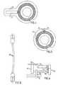
- Fig. 5shows an embodiment of the invention which likewise is identical to the embodiment of Figs. 1-3, except that the motor 22 is encapsulated in the hose 8 so that it is fixed to the core 2 and has a short drive shaft 32, the motor 22 being positioned relative to the core 2 such that the drive shaft 32 extends substantially tangentially to the circular core 2. There is an angular gearing 34 connecting the drive shaft 32 to the drive wheel 14.
- Fig. 6shows a suitable arrangement for the motor 22 in the embodiment of Fig. 5, comprising a first clamping member 36 secured to one end portion of the core 2 and a second clamping member 38 secured to the other end portion 6 of the core 2.
- the motor 22is secured to the first clamping member 36 and is operatively connected to a worm 40 via a gear transmission 42.
- the worm 40is journalled at its opposite ends on holders 44 and 46, which are rigidly secured to the clamping member 36 and the motor 22, respectively.
- the second clamping member 38has a pinion in mesh with the worm 40.
- Fig. 7shows an embodiment of the invention in which a restriction member comprises an elongated core 48 and a helical spring 50.
- a spring contracting meansin the form of a flexible pulling member 52, i.e. a string, wire or cable, is connected to the core 48 at one end thereof and extends through the helical spring 50.
- a hydralic motor in the form of a cylinder/piston unit 54is adapted to pull the flexible pulling member 52. to contract the helical spring 50 against an arresting member 56, which is fixed relative to the core 48.
- FIG. 8shows a similar embodiment in which a hydraulic transmission conduit 59 is provided between two piston-cylinder assemblies 54, for use as the hydraulic motor/device in Fig. 7.
- Fig. 9shows an embodiment of the invention in which the restriction member comprises two elongated helical springs 60 and 62 having free ends, and a body 64 to which the springs 60,62 are nonrotatably secured at their opposite ends.
- the body 64comprises two separate parts secured to opposite end portions of the enclosing elastic hose 8 and is designed with a releasable and lockable joint between the separate parts.
- An adjustment means in the form of a drive shaft 66has two opposite end portions connected to the helical springs 60,62, respectively, at their free ends.
- the coils of the springs 60,62form left and right hand helices, respectively.
- a motor 68is adapted to rotate the drive shaft 66 in one direction to enlarge the coils of the helical springs 60,62 to longitudinally contract the springs 60,62 and to rotate the drive shaft 66 in the opposite direction to reduce the size of the coils of the springs 60,62 to longitudinally extend the springs 60,62.
- the elongated helical springs 60,62defines a restriction opening, the size of which is increased when the springs 60,62 are extended and decreased when the springs 60,62 are contracted.
- Fig. 10shows an embodiment according to the invention which is identical to the embodiment of Fig.9, except that the adjustment means comprises a gearing having an input shaft 72 and two opposite aligned output shafts 74 and 76 connected to the helical springs 60 and 62, respectively, at their free ends.
- the input shaft 72is connected to the output shafts 74,76 such that they rotate at opposite directions upon rotation of the input shaft 72.
- the coils of the springs 60, 62form the same helices.
- Figs. 11-14show an embodiment of the device of the invention in which a hydraulic motor comprises two interconnected cylinders 78 and 80 and two pistons 82 and 84 in the respective cylinders 78,80.
- the cylinders 78,80have a common fluid supply inlet member 86, which together with the cylinders 78,80 takes the shape of a Y-pipe.
- the restriction membercomprises an elongated resilient arcuate core 88.
- the adjustment meanscomprises two bars 90 and 92 secured to opposite ends of the core 88 and connected to the pistons 82 and 84, respectively.
- the core 88defines a restriction opening and is provided with a releasable and lockable joint 94 (Fig.
- the core 88 and the cylinders 90,92are enclosed by a soft elastic hose 96 except at the joint 94 and the inlet member 86.
- the hose 96has an outer tubular wall 98 and a central coaxial inner tubular wall 100, which is fixed to the outer wall 98 by spoke members 102 (Fig. 14).
- the core 88is loosely fit in the inner tubular wall 100.
- Figs. 15-17show an embodiment of the invention which is identical to the embodiment of Figs. 11-14, except that the adjustment means comprises an elongated voltage responsive element 104 secured to the opposite ends of the core 88, so that the core 88 and the element 104 form the restriction member.
- the element 104is capable of bending inwardly into a bow in response to a voltage applied across the element 104.
- the radius of curvature of said bowis adjustable by changing the level of the voltage applied to element 104.
- Fig. 18shows an embodiment of the device of the invention comprising a loop forming means in the form of a substantially rigid outer circular element 106 with a releasable and lockable joint 108 to enable application of the device around the esophagus or stomach.
- the restriction membercomprises an elastic inner circular element 110 formed by the innermost wall portion of an elastic hose 112 extending along the outer element 106.
- the inner circular element 110is disposed concentrically within the outer circular element 106.
- the adjustment meanscomprises a plurality of threads 114 secured to the elastic inner element 110 along the circumference thereof and running from the inner element 110 via guide members 116 attached to the outer element 106. By pulling all the threads 114 the inner elastic element 110 is pulled under expansion radially outwardly towards the outer element 106.
- Fig. 19shows an embodiment which is identical to the embodiment of Fig, 9, except that it comprises a loop forming means in the form of a substantially rigid outer circular element 118 supporting the helical springs 60,62, and a soft elastic inner wall 120 extending along the springs 60,62.
- the motor 68rotates the helical springs 60, 62 in a direction that enlarges the coils of the springs 60,62, the coils are forced by the rigid outer element 118 to expand radially inwardly thereby reducing the size of the restriction opening formed by the circumferential confinement surface of the restriction member (springs 60,62 and body 64).
- Fig. 20shows an embodiment of the invention in which a restriction member comprises a plurality of arcuate lamellae 122 arranged like the conventional adjustable aperture mechanism of a camera.
- the adjustment meansis conventional and is operated by a motor 124 to adjust the lamellae 122 to change the size of an restriction opening defined by the lamellae 122.
- Figs. 21-23show an embodiment of the invention in which a restriction member comprises two semi-circular elements 126 and 128 which are hinged together such that the semi-circular elements 126,128 are swingable relative to each other between a fully open state in which they substantially form a circle, illustrated in Fig, 22 and an angular state, in which the size of the restriction opening defined by the semi-circular elements 126,128 is reduced, illustrated in Fig, 23.
- the adjustment meansis conventional and is operated by a motor 130 to swing the semi-circular elements 126,128 relative to each other.
- Figs. 24-27show an embodiment of the invention in which the restriction member comprises an elastic belt 130 forming a circle and having a substantially oval cross-section.
- the restriction member 130is provided with a releasable and lockable joint 132.
- An elastic double walled hose 134encloses the belt 130 except at the joint 132.
- the adjustment meansis conventional and is operated by a motor 136 to turn the belt 130 around the longitudinal extension thereof between a fully open state, in which the inner broader side of the belt 130 forms a substantially cylindrical surface, illustrated in Fig. 26, and a reduced open state, in which the inner broader side of the belt 130 forms a substantially conical surface, illustrated in Fig. 27.
- Fig. 28schematically illustrates a cushion arrangement for protecting the esophagus or stomach, comprising a plurality of cushions 138 disposed in series along a substantially circular holding member 140.
- This cushion arrangementmay be utilized in any of the above described embodiments of the invention.
- Figs. 29A-Dprovide a block diagram of four different hydraulic transmission configurations.
- Fig. 29Ashows an adjustment means 202 of the restriction member, a separate reservoir 204, a one way pump 206 and an alternate valve 208.
- Fig. 29Bshows the adjustment means 202 and an adjustable reservoir 210.
- Fig. 29Cshows the adjustment means 202, a two way pump 212 and the reservoir 204.
- Fig. 30Dshows a servo system with a first closed system controlling a second system.
- the servo systemcomprises the adjustable reservoir 210 and a passive adjustable reservoir 214. Any of the reservoirs can be the active reservoir, either the servo reservoir 210 or the fluid supply reservoir 214.
- the reservoir 214controls a larger adjustable reservoir 216 which is used for the operation of the adjustment means 202 for changing the restriction opening of the restriction member.
- Figs. 30A-Dare cross-sectional views of a pump mechanism adapted to pump fluid in both directions only by mechanically pushing a separate sealing wall portion 218 in one direction.
- Fig 30Ashows a piston 220 pushed forwards against a spring 222 towards the wall portion 218 and located in a pump housing 224 conducting fluid from a right upper fluid passage 226 of the housing 224 to a left fluid passage 228 of the housing 224.
- a main valve 230is open and a nonreturn valve 232 is closed.
- Fig. 30Billustrates the first pump movement in which the piston 220 has moved forwards and reaches the wall portion 218.
- Fig. 30Cillustrates how the piston 220 moves backwards by the action of the spring 222.
- Fig. 30Dillustrates how the piston 220 is moved further downwards from its position according to Fig. 30B while pushing the wall portion 218 downwards against a second spring 234 that is stronger than spring 222, so that fluid escapes from a right lower fluid passage 236.
- a second spring 234that is stronger than spring 222
- Fig 31is a cross-sectional view of a reservoir 240 defining a chamber 242, the size of which is variable and is controlled by a remote controlled motor 244, in accordance with Fig. 29B or 29D.
- the reservoir 240 and the motor 244are placed in a housing 246.
- the chamber 242is varied by moving a large wall 248.
- the wall 248is secured to a nut 250, which is threaded on a rotatable spindle 252.
- the spindle 252is rotated by the motor 244 via an angular gearing, which comprises two conical gear wheels 254 and 256 in mesh with each other.
- the motor 244is powered by a battery 258 placed in the housing 246.
- a signal receiving means 260 for controlling the motor 244is also placed in the housing 246.
- the battery 258 and the signal receiving means 260may be mounted in a separate place.
- the signal receiving meansmay comprise any known or conventional device which is capable of receiving a control signal and then operating the motor 244.
- Fig. 32is a cross-sectional view of a reservoir 262 defining a chamber 264, the size of which is variable and is controlled by manual manipulation.
- a gable wall portion 266 of an open ended inner cylindrical housing 68is adapted to be pushed downwards to fit in a desired locking groove 270 of a plurality of locking grooves 270 on the mantle wall of the cylindrical housing 268, to reduce the size of the chamber 64.
- the inner cylindrical housing 268is suspended by springs 272 and is telescopically applied on an outer cylindrical housing 274. When pushing the inner cylindrical housing 268 it moves downwards relative to the outer cylindrical housing 274 causing the gable wall portion 266 to release from the locking groove 270 and move upwards relative to the inner cylindrical housing 268.
- the inner housing 268is moved upwardly by the action of the springs 272 the size of the chamber 264 is increased.
- Fig. 33A and 33Bshow a servo means comprising a main ring-shaped fluid reservoir 276 defining a chamber 278, the size of which is variable. Centrally positioned in the main ring-shaped reservoir 276 there is a servo fluid reservoir 280 defining a chamber 282, the size of which is variable.
- the chamber 282 of the servo reservoir 280is significantly smaller than the chamber 278 of the main reservoir 276.
- the two reservoirs 276 and 280are situated between two opposite separate walls 284 and 286, and are secured thereto. When changing the amount of fluid in the servo reservoir 280, the two opposite walls 284,286 are moved towards or away from each other, whereby the size of the chamber 278 of the main reservoir 276 is changed.
- Fig. 34shows the basic parts of a remote control system of the implantable device of the invention including a motor, for instance the electric motor 22.
- the remote control systemis based on the transmission of electromagnetic wave signals, often of high frequencies in the order of 100 kHz - 1 gHz, through the skin 330 of the patient.
- all parts placed to the left of the skin 330are located outside the patient's body and all parts placed to the right of the skin 330 are implanted in the patient's body.
- An external signal transmitting antenna 332is to be positioned close to a signal receiving antenna 334 implanted in the patient's body close to the skin 330.
- the receiving antenna 334may be placed for example inside the abdomen of the patient.
- the receiving antenna 334comprises a coil, approximately 1-100 mm, preferably 25 mm in diameter, wound with a very thin wire and tuned with a capacitor to a specific high frequency.
- a small coilis chosen if it is to be implanted under the skin of the patient and a large coil is chosen if it is to be implanted in the abdomen of the patient.
- the transmitting antenna 332comprises a coil having about the same size as the coil of the receiving antenna 334 but wound with a thick wire that can handle the larger currents that is necessary.
- the coil of the transmitting antenna 332is tuned to the same specific high frequency as the coil of the receiving antenna 334.
- An external control unit 336comprises a microprocessor, a high frequency electromagnetic signal generator and a power amplifier.
- the microprocessor of the control unit 336is adapted to switch on/off the generator and to modulate signals generated by the generator to send digital information via the power amplifier and the antennas 332,334 to an implanted control unit 338.
- digital signal codesare used.
- a keypad placed on the external control unit 336is connected to the microprocessor thereof. The keypad.is used to order the microprocessor to send digital signals to either increase or decrease the size of the restriction opening defined by the loop of the restriction member (e.g. as described above).
- the microprocessorstarts a command by applying a high frequency signal on the antenna 332.
- commandsare sent to increase or decrease the size of the restriction opening of the restriction member in predefined steps.
- the commandsare sent as digital packets in the form illustrated below. Start pattern, 8 bits Command, 8 bits Count, 8 bits Checksum, 8 bits
- the commandsare sent continuously during a rather long time period (e.g. 30 seconds or more).
- a rather long time periode.g. 30 seconds or more.
- an implanted energizer unit 326draws energy from the high frequency electromagnetic wave signals received by the receiving antenna 334.
- the energizer unit 326stores the energy in a power supply, such as a large capacitor, powers the control unit 338 and powers the electric motor 22 via a line 342.
- the control unit 338comprises a demodulator and a microprocessor.
- the demodulatordemodulates digital signals sent from the external control unit 336.
- the microprocessor of the control unit 338receives the digital packet, decodes it and, provided that the power supply of the energizer unit 326 has sufficient energy stored, sends a signal via a signal line 344 to the motor 22 to either increase or decrease the size of the restriction opening of the restriction member depending on the received command code.
- the energy stored in the power supply of the energizer unitmay only be used for powering a switch, and the energy for powering the motor 22 may be obtained from another implanted power source of relatively high capacity, for example a battery.
- the switchis adapted to connect the battery to the control unit 338 in an "on" mode when said switch is powered by said power supply and to keep said battery disconnected from the control unit in a "standby" mode when the switch is unpowered.
- the external control unit 336comprises a microprocessor 346, a signal generator 348 and a power amplifier 350 connected thereto.
- the microprocessor 346is adapted to switch the signal generator 348 on/off and to modulate signals generated by the signal generator 348 with digital commands that are sent to implanted components of the device of the invention.
- the power amplifier 350amplifies the signals and sends them to the external signal transmitting antenna 332.
- the antenna 332is connected in parallel with a capacitor 352 to form a resonant circuit tuned to the frequency generated by the signal generator 348.
- the implanted signal receiving antenna coil 334forms together with a capacitor 354 a resonant circuit that is tuned to the same frequency as the transmitting antenna 332.
- the signal receiving antenna coil 334induces a current from the received high frequency electromagnetic waves and a rectifying diode 360 rectifies the induced current, which charges a storage capacitor 358.
- a coil 356 connected between the antenna coil 334 and the diode 360prevents the capacitor 358 and the diode 360 from loading the circuit of the signal receiving antenna 334 at higher frequencies.
- the coil 356makes it possible to charge the capacitor 358 and to transmit digital information using amplitude modulation.
- a capacitor 362 and a resistor 364 connected in parallel and a diode 366forms a detector used to detect amplitude modulated digital information.
- a filter circuitis formed by a resistor 368 connected in series with a resistor 370 connected in series with a capacitor 372 connected in series with the resistor 368 via ground, and a capacitor 374, one terminal of which is connected between the resistors 368,370 and the other terminal of which is connected between the diode 366 and the circuit formed by the capacitor 362 and resistor 364.
- the filter circuitis used to filter out undesired low and high frequencies.
- the detected and filtered signalsare fed to an implanted microprocessor 376 that decodes the digital information and controls the motor 22 via an H-bridge 378 comprising transistors 380,382,384 and 386.
- the motor 22can be driven in two opposite directions by the H-bridge 378.
- the microprocessor 376also monitors the amount of stored energy in the storage capacitor 358. Before sending signals to activate the motor 22, the microprocessor 376 checks whether the energy stored in the storage capacitor 358 is enough. If the stored energy is not enough to perform the requested operation, the microprocessor 376 waits for the received signals to charge the storage capacitor 358 before activating the motor 22.
- control unitmay be replaced by discrete components.
- the power amplifier of the external control unitmay be omitted if the signals generated by the signal generator are strong enough. Therefore the invention is to be accorded the broadest interpretation of the appended claims to encompass all equivalent structures and assemblies.
- One further advantage with this inventionis that there may be a night button on the remote control setting the adjustment means in a position with a larger stoma diameter during the night, thus avoiding vomiting or nausa.
Landscapes
- Health & Medical Sciences (AREA)
- Animal Behavior & Ethology (AREA)
- Public Health (AREA)
- Nursing (AREA)
- Orthopedic Medicine & Surgery (AREA)
- Engineering & Computer Science (AREA)
- Biomedical Technology (AREA)
- Heart & Thoracic Surgery (AREA)
- Vascular Medicine (AREA)
- Life Sciences & Earth Sciences (AREA)
- Veterinary Medicine (AREA)
- Obesity (AREA)
- General Health & Medical Sciences (AREA)
- Child & Adolescent Psychology (AREA)
- Prostheses (AREA)
- Surgical Instruments (AREA)
- Orthopedics, Nursing, And Contraception (AREA)
- Massaging Devices (AREA)
- Iron Core Of Rotating Electric Machines (AREA)
- Valves And Accessory Devices For Braking Systems (AREA)
- Endoscopes (AREA)
- Food-Manufacturing Devices (AREA)
- Table Devices Or Equipment (AREA)
Abstract
Description
| Start pattern, 8 bits | Command, 8 bits | Count, 8 bits | Checksum, 8 bits |
Claims (54)
- A food intake restriction device for forming a stoma opening in the stomach oresophagus of a patient, the device comprising:an elongated restriction member (2, 48, 60, 62, 88, 110, 122, 126, 128, 130);forming means (10, 94, 106, 108, 118, 132) for forming the elongated restrictionmember into at least a substantially closed loop around the stomach or esophagus, saidloop defining a restriction opening (3);an adjustment means (12, 52, 66, 90, 92, 104, 110) for adjusting the restrictionmember in said loop to change the size of said restriction opening,wherein the adjustment means is designed to mechanicallyadjust the restriction member in a non invasive manner toallow post operation non invasive adjustment of the restriction member;an implantablesignal receiving means (334, 338) comprising a control unit for controlling the adjustment means in response to signals from a wireless remote transmittingmeans; andan implantable energizer unit for providing energy to energy consumingcomponents of the device,characterised in that:the energizer unit is capable of being provided with energy via wireless energytransfer from the signal transmitting means.
- The device according to claim 1, wherein the adjustment means comprises means(12, 52, 66, 90, 92) for adjusting the longitudinal extension of the elongated restrictionmember (2, 48, 60, 62, 88) in said loop.
- The device according to claim 2, wherein the restriction member (2, 48) comprisesa main portion and two elongated end portions (4, 6), and the adjustment means comprisesmeans (12, 52, 66, 90, 92) for establishing longitudinal relative displacement between theend portions of the restriction member, such that the size of said restriction opening (3) isadjusted.
- The device according to claim 3, wherein the adjustment means (12, 52, 66, 90, 92)comprises a movement transferring member (14, 40, 78, 90, 80, 92) in engagement with atleast one of the end portions (4, 6) of the restriction member and operable to displace saidone end portion relative to the other end portion of the restriction member.
- The device according to claim 4, further comprising a motor (22), which is fixedrelative to the main portion of the restriction member (2) and has a rotating drive shaft (32)operatively connected to the movement transferring member (14).
- The device according to claim 5, wherein the motor is positioned relative to theelongated restriction member such that the drive shaft extends in parallel with a chord insaid loop of the restriction member.
- The device according to claim:2, wherein the elongated restriction member (48, 50)is longitudinally resilient and the adjustment means comprises a contracting means (52) forlongitudinally contracting the resilient restriction member.
- The device according to claim 7, wherein the elongated restriction membercomprises a substantially nonresilient main portion (48) and an end portion forming anelongated helical spring (50), which is contractable by the contracting means (52).
- The device according to claim 8, wherein the contracting means comprises anelongated flexible pulling member (52) connected to the main portion (48) of therestriction member and extending through the helical spring (50) to contract the helicalspring against an arresting member (56), which is fixed relative to the main portion of therestriction member.
- The device according to claim 2, wherein the restriction member comprises anelongated helical spring (60) having a free end, and a body (64) to which said spring isnonrotatably secured at its opposite end, the adjustment means (66) is for rotating thehelical spring in one direction to enlarge the coils of the helical spring to longitudinallycontract the elongated helical spring and for rotating the helical spring in the oppositedirection to reduce the size of the coils of the helical spring to longitudinally extend thehelical spring.
- The device according to claim 10, wherein the restriction member comprises afurther elongated helical spring (62) having a free end and nonrotatably secured to thebody (64) at its opposite end, and the adjustment means comprises a drive shaft (66) having two opposite end portions connected to the helical springs, respectively, at theirfree ends, the helical coils forming left and right hand helices, respectively.
- The device according to claim 11, wherein the restriction member comprises afurther elongated helical spring (62) having a free end and nonrotatably secured to thebody (64) at its opposite end, and the adjustment means comprises a gearing (70) having aninput shaft (78) and two opposite aligned output shafts (74, 76) connected to the helicalsprings (60, 62), respectively, at their free ends, the input shaft being connected to theoutput shafts such that the output shafts rotate in the opposite directions upon rotation ofthe input shaft, the helical coils forming the same helices.
- The device according to claim 1, wherein the restriction member (88, 110, 122)forms a radially innermost circumferential confinement surface in said loop of therestriction member, and the adjustment means (104, 112) is for mechanically adjusting therestriction member such that at least a portion of the confinement surface is substantiallyradially displaced in said loop.
- The device according to claim 13, wherein the adjustment means comprises anelongated voltage responsive element (104) forming part of the confinement surface andcapable of bending into a bow in response to a voltage applied across the element, theradius of curvature of said bow being adjustable by changing the level of the voltage.
- The device according to claim 13, wherein the restriction member comprises anelastic annular element (110) forming the confinement surface, and the adjustment means(112) is for changing the diameter of the elastic annular element.
- The device according to claim 13, wherein the forming means comprises asubstantially rigid outer annular element (118), and the restriction member comprises anelongated helical spring (60) extending internally along the outer annular element andcontacting the latter, the helical spring forming part of the circumferential confinementsurface and having a free end, and a body to which the helical spring is nonrotatablysecured at its opposite end,the adjustment means is for rotating the helical spring in onedirection to enlarge the coils of the helical spring to contract the circumferential confinement surface and for rotating the helical spring in the opposite direction to reducethe size of the coils of the helical spring to expand the circumferential confinement surface.
- The device according to claim 13, wherein the forming means comprises asubstantially rigid outer annular element (118), and the restriction member comprises afirst (60) and a second (62) elongated helical spring extending internally along the outerannular element and contacting the latter, the helical springs forming part of thecircumferential confinement surface, the first and the second spring, respectively, having afree end, and a body to which the first and the second spring, respectively, is nonrotatablysecured at its opposite end, the adjustment means is for rotating the first and the secondspring, respectively, in one direction to enlarge the coils of the spring to contract thecircumferential confinement surface and for rotating the first and the second spring,respectively, in the opposite direction to reduce the size of the coils of the spring to expandthe circumferential confinement surface.
- The device according to claim 1, wherein the restriction member comprises at leasttwo separate elements, at least one of which is pivoted such that it is turnable in a plane inwhich said loop of the restriction member extends, and the adjustment means is for turningsaid pivoted element to change the size of said restriction opening.
- The device according to claim 1, wherein the restriction member comprises at leasttwo frame elements (126, 128), which are foldable towards each other by the adjustmentmeans.
- The device according to claim 19, wherein the foldable frame elements comprisetwo substantially semi-circular frame elements (126, 128), which are hinged together suchthat the semi-circular elements are swingable relative to each other from a fully open statein which they substantially form a circle to a fully folded state in which they form a semi-circle.
- The device according to claim 1, wherein the elongated restriction member (130) iselastic and varies in thickness as seen in a cross-section therethrough, and the adjustmentmeans is for turning the restriction member around the longitudinal extension thereof.
- The device according to claim 1, further comprising a motor (22, 68, 124, 130, 136)operatively connected to the adjustment means (12, 52, 66, 90, 92, 104, 110).
- The device according to claim 22, wherein the motor (22, 68, 124, 130, 136) isfixed to the restriction member.
- The device according to claim 23, wherein the motor (22) is remote from the therestriction member (2) and is connected to the adjustment means (14) by a powertransmission conduit (24).
- The device according to claim 1, further comprising hydraulic means (54) foroperating the adjustment means (52).
- The device according to claim 25, further comprising a reservoir (204, 210, 216)containing a predetermined amount of fluid for supplying the hydraulic means with fluid.
- The device according to claim 26, wherein the reservoir (210) defines a chamberfor the predetermined amount of fluid and the hydraulic means (202) is for changing thesize of the chamber.
- The device according to claim 26, wherein the hydraulic means comprises anactivatable pump (212) for pumping fluid between the reservoir (204) and the adjustmentmeans (202).
- The device according to claim 26, wherein the hydraulic means comprises a servomeans (210, 214, 276-286).
- The device according to claim 29, wherein the hydraulic means comprises first andsecond wall portions of the reservoir (204), and the servo means is for providing relativedisplacement between the first and second wall portions of the reservoir.
- The device according to claim 1, further comprising a wireless remote controlmeans (22, 326, 332-344) for non-invasively controlling the adjustment means.
- The device according to claim 31, wherein the remote control means (22, 326, 332-344)comprises a separate signal transmitting means (332, 336).
- The device according to claim 1, further comprising an implantable motor (22) foroperating the adjustment means (12, 52, 66, 90, 92, 104, 110).
- The device according to claim 33, wherein the control unit (338) is for poweringthe motor (22) with energy provided by the energizer unit (336) in response to signalsreceived from the signal transmitting means (332, 336).
- The device according to claim 33, wherein the motor (22) is an electric motor.
- The device according to claim 1, wherein the energizer unit (326) is fortransfering energy from the signals, as they are transmitted to the signal receiving means(334, 338), into electric energy.
- The device according to claim 36, further comprising an implantable electric motor(22) for operating the adjustment means (12, 52, 66, 90, 92, 104, 110), the energizer unit(326) comprising a rechargeable electric power supply (58) for storing the electric energyand the control unit (338) is for powering the electric motor (22) with energy from therechargeable electric power supply in response to signals received from the signaltransmitting means (332, 336).
- The device according to claim 33, wherein the energizer unit (326) comprises abattery, an electrically operable switch for connecting the battery to the signal receivingmeans in (334, 338) an "on" mode when the switch is powered and to keep the battery disconnected from the signal receiving means in a "standby" mode when the switch isunpowered, and a rechargeable electric power supply for powering the switch.
- The device according to claim 38, wherein the control unit (338) is for poweringthe electric motor (22) with energy from the battery in response to signals received fromthe signal transmitting means (332, 336), when the switch is in its "on" mode.
- The device according to claim 2, wherein the forming means comprises a springmaterial forming the elongated restriction member into said loop, such that the restrictionopening has a predetermined size, and the adjustment means is for adjusting the restrictionmember against the spring action of the spring material.
- The device according to claim 41, wherein the spring material is integrated in therestriction member.
- The device according to any of the preceding claims, wherein the forming means(10, 94, 106, 108, 118, 132) is for forming the restriction member (2, 48, 60, 62, 88, 110,122, 126, 128, 130) into a loop having a predetermined size.
- The device according to claim 31, wherein the remote control means (22, 326, 332-344)comprises means for wireless transfer of energy from outside the patient's body toenergy consuming implantable components of the device.
- The device according to claim 43, further comprising an implantable motor (22) foroperating the adjustment means (12, 52, 66, 90, 92, 104, 110), said means for wirelesstransfer of energy for directly powering the motor with transferred energy.
- The device according to claim 43 or 44, wherein the energy transferred by saidmeans for transfer of energy comprises wave signals.
- The device according to claim 43 or 44, wherein the energy transferred by saidmeans for transfer of energy comprises an electric field or a magnetic field.
- The device according to claim 32, wherein the signal transmitting means(332, 336) and signal receiving means (334, 338) are for transmitting and receiving signalsin the form of digital pulses.
- The device according to claim 47, wherein the digital pulses comprise a magneticfield or an electric field.
- The device according to claim 32, wherein the signal transmitting means(332, 336) and signal receiving means (334, 338) are for transmitting and receiving wavesignals.
- The device according to claim 49, wherein the wave signals compriseelectromagnetic waves, sound waves or carrier waves for remote control signals.
- The device according to claim 1 or 36, wherein the energizer unit (26) is fortransferring the energy from the signals into direct or alternating current.
- The device according to claim 31, wherein the remote control means (22, 326, 332-344)is capable of obtaining information on the size of the restriction opening (3) andcommanding the adjustment means (12, 52, 66, 90, 104, 110) to adjust the restrictionmember (2, 48, 60, 62, 88, 110, 122, 126, 128, 130) in response to obtained information.
- The device according to claim 1, wherein the adjustment means (12, 52, 66, 90,104, 110) is for changing the size of the restriction opening (3) such that the outercircumferential confinement surface of the restriction member (2, 48, 60, 62, 88, 110, 122,126, 128, 130) is changed.
- The device according to claim 1, wherein the adjustment means (12, 52, 66, 90,104, 110) is for changing the size of the restriction opening (3) such that the outercircumferential confinement surface of the restriction member (2, 48, 60, 62, 88, 110, 122,126, 128, 130) is unchanged.
Priority Applications (2)
| Application Number | Priority Date | Filing Date | Title |
|---|---|---|---|
| EP05075710AEP1554996B1 (en) | 1998-08-13 | 1999-08-12 | Food intake restriction device |
| DE69925130.3TDE69925130T3 (en) | 1998-08-13 | 1999-08-12 | APPARATUS FOR EATING |
Applications Claiming Priority (3)
| Application Number | Priority Date | Filing Date | Title |
|---|---|---|---|
| US09/133,320US6067991A (en) | 1998-08-13 | 1998-08-13 | Mechanical food intake restriction device |
| US133320 | 1998-08-13 | ||
| PCT/SE1999/001365WO2000009047A1 (en) | 1998-08-13 | 1999-08-12 | Food intake restriction device |
Related Child Applications (2)
| Application Number | Title | Priority Date | Filing Date |
|---|---|---|---|
| EP05075710ADivisionEP1554996B1 (en) | 1998-08-13 | 1999-08-12 | Food intake restriction device |
| EP05075710.3Division-Into | 2005-03-25 |
Publications (3)
| Publication Number | Publication Date |
|---|---|
| EP1105073A1 EP1105073A1 (en) | 2001-06-13 |
| EP1105073B1true EP1105073B1 (en) | 2005-05-04 |
| EP1105073B2 EP1105073B2 (en) | 2013-09-18 |
Family
ID=22458030
Family Applications (2)
| Application Number | Title | Priority Date | Filing Date |
|---|---|---|---|
| EP05075710AExpired - LifetimeEP1554996B1 (en) | 1998-08-13 | 1999-08-12 | Food intake restriction device |
| EP99943570.4AExpired - LifetimeEP1105073B2 (en) | 1998-08-13 | 1999-08-12 | Food intake restriction device |
Family Applications Before (1)
| Application Number | Title | Priority Date | Filing Date |
|---|---|---|---|
| EP05075710AExpired - LifetimeEP1554996B1 (en) | 1998-08-13 | 1999-08-12 | Food intake restriction device |
Country Status (11)
| Country | Link |
|---|---|
| US (1) | US6067991A (en) |
| EP (2) | EP1554996B1 (en) |
| AT (2) | ATE383834T1 (en) |
| AU (1) | AU746408B2 (en) |
| BR (1) | BR9912791A (en) |
| CA (1) | CA2338200C (en) |
| DE (2) | DE69938014T2 (en) |
| DK (1) | DK1105073T4 (en) |
| ES (2) | ES2298923T3 (en) |
| MX (1) | MXPA01000602A (en) |
| WO (1) | WO2000009047A1 (en) |
Cited By (21)
| Publication number | Priority date | Publication date | Assignee | Title |
|---|---|---|---|---|
| US8236023B2 (en) | 2004-03-18 | 2012-08-07 | Allergan, Inc. | Apparatus and method for volume adjustment of intragastric balloons |
| US8251888B2 (en) | 2005-04-13 | 2012-08-28 | Mitchell Steven Roslin | Artificial gastric valve |
| US8308630B2 (en) | 2006-01-04 | 2012-11-13 | Allergan, Inc. | Hydraulic gastric band with collapsible reservoir |
| US8317677B2 (en) | 2008-10-06 | 2012-11-27 | Allergan, Inc. | Mechanical gastric band with cushions |
| US8377081B2 (en) | 2004-03-08 | 2013-02-19 | Allergan, Inc. | Closure system for tubular organs |
| US8382780B2 (en) | 2002-08-28 | 2013-02-26 | Allergan, Inc. | Fatigue-resistant gastric banding device |
| US8517915B2 (en) | 2010-06-10 | 2013-08-27 | Allergan, Inc. | Remotely adjustable gastric banding system |
| US8758221B2 (en) | 2010-02-24 | 2014-06-24 | Apollo Endosurgery, Inc. | Source reservoir with potential energy for remotely adjustable gastric banding system |
| US8840541B2 (en) | 2010-02-25 | 2014-09-23 | Apollo Endosurgery, Inc. | Pressure sensing gastric banding system |
| US8845513B2 (en) | 2002-08-13 | 2014-09-30 | Apollo Endosurgery, Inc. | Remotely adjustable gastric banding device |
| US8876694B2 (en) | 2011-12-07 | 2014-11-04 | Apollo Endosurgery, Inc. | Tube connector with a guiding tip |
| US8900118B2 (en) | 2008-10-22 | 2014-12-02 | Apollo Endosurgery, Inc. | Dome and screw valves for remotely adjustable gastric banding systems |
| US8900117B2 (en) | 2004-01-23 | 2014-12-02 | Apollo Endosurgery, Inc. | Releasably-securable one-piece adjustable gastric band |
| US8905915B2 (en) | 2006-01-04 | 2014-12-09 | Apollo Endosurgery, Inc. | Self-regulating gastric band with pressure data processing |
| US8961393B2 (en) | 2010-11-15 | 2015-02-24 | Apollo Endosurgery, Inc. | Gastric band devices and drive systems |
| US8961394B2 (en) | 2011-12-20 | 2015-02-24 | Apollo Endosurgery, Inc. | Self-sealing fluid joint for use with a gastric band |
| US9028394B2 (en) | 2010-04-29 | 2015-05-12 | Apollo Endosurgery, Inc. | Self-adjusting mechanical gastric band |
| US9044298B2 (en) | 2010-04-29 | 2015-06-02 | Apollo Endosurgery, Inc. | Self-adjusting gastric band |
| US9050165B2 (en) | 2010-09-07 | 2015-06-09 | Apollo Endosurgery, Inc. | Remotely adjustable gastric banding system |
| US9192501B2 (en) | 2010-04-30 | 2015-11-24 | Apollo Endosurgery, Inc. | Remotely powered remotely adjustable gastric band system |
| US9295573B2 (en) | 2010-04-29 | 2016-03-29 | Apollo Endosurgery, Inc. | Self-adjusting gastric band having various compliant components and/or a satiety booster |
Families Citing this family (278)
| Publication number | Priority date | Publication date | Assignee | Title |
|---|---|---|---|---|
| WO2000015140A1 (en)* | 1998-09-15 | 2000-03-23 | Infinite Biomedical Technologies, Incorporated | Intraurethral continent prothesis |
| US8666495B2 (en) | 1999-03-05 | 2014-03-04 | Metacure Limited | Gastrointestinal methods and apparatus for use in treating disorders and controlling blood sugar |
| US9101765B2 (en) | 1999-03-05 | 2015-08-11 | Metacure Limited | Non-immediate effects of therapy |
| US6973347B1 (en)* | 1999-05-26 | 2005-12-06 | Impulse Dynamics Nv | Local cardiac motion control using applied electrical signals and mechanical force |
| US20050192629A1 (en)* | 1999-06-25 | 2005-09-01 | Usgi Medical Inc. | Methods and apparatus for creating and regulating a gastric stoma |
| EP1072282A1 (en)* | 1999-07-19 | 2001-01-31 | EndoArt S.A. | Flow control device |
| US6471635B1 (en) | 2000-02-10 | 2002-10-29 | Obtech Medical Ag | Anal incontinence disease treatment with controlled wireless energy supply |
| US6464628B1 (en)* | 1999-08-12 | 2002-10-15 | Obtech Medical Ag | Mechanical anal incontinence |
| US6482145B1 (en) | 2000-02-14 | 2002-11-19 | Obtech Medical Ag | Hydraulic anal incontinence treatment |
| US6450173B1 (en) | 1999-08-12 | 2002-09-17 | Obtech Medical Ag | Heartburn and reflux disease treatment with controlled wireless energy supply |
| FR2799118B1 (en)* | 1999-10-01 | 2002-07-12 | Medical Innovation Dev | ADJUSTABLE GASTRIC IMPLANT |
| US6600953B2 (en) | 2000-12-11 | 2003-07-29 | Impulse Dynamics N.V. | Acute and chronic electrical signal therapy for obesity |
| AU764705B2 (en) | 2000-02-10 | 2003-08-28 | Implantica Patent Ltd. | Urinary incontinence treatment with wireless energy supply |
| CA2635435C (en) | 2000-02-10 | 2010-05-25 | Potencia Medical Ag | Controlled urinary incontinence treatment |
| US6470892B1 (en)* | 2000-02-10 | 2002-10-29 | Obtech Medical Ag | Mechanical heartburn and reflux treatment |
| ATE391468T1 (en) | 2000-02-10 | 2008-04-15 | Potencia Medical Ag | MECHANICAL DEVICE FOR IMPOTENCY TREATMENT |
| ATE416743T1 (en) | 2000-02-11 | 2008-12-15 | Potentica Ag | DEVICE WITH ENERGY CONVERSION MEANS FOR TREATING IMPOTENCY |
| CA2396224C (en)* | 2000-02-11 | 2011-07-12 | Potencia Medical Ag | Controlled impotence treatment |
| US20030100929A1 (en) | 2000-02-14 | 2003-05-29 | Peter Forsell | Controlled penile prosthesis |
| WO2001047440A2 (en) | 2000-02-14 | 2001-07-05 | Potencia Medical Ag | Male impotence prosthesis apparatus with wireless energy supply |
| US7442165B2 (en) | 2000-02-14 | 2008-10-28 | Obtech Medical Ag | Penile prosthesis |
| US6527701B1 (en)* | 2000-09-29 | 2003-03-04 | Precision Medical Devices, Inc. | Body fluid flow control device |
| EP1202145B1 (en)* | 2000-10-27 | 2005-02-09 | Invensys Systems, Inc. | Field device with a transmitter and/ or receiver for wireless data communication |
| US7033373B2 (en) | 2000-11-03 | 2006-04-25 | Satiety, Inc. | Method and device for use in minimally invasive placement of space-occupying intragastric devices |
| JP4246492B2 (en)* | 2001-01-05 | 2009-04-02 | メタキュアー ナームロゼ フェンノートシャップ | Regulation of eating habits |
| CN1270667C (en) | 2001-04-18 | 2006-08-23 | 超治疗股份有限公司 | Analysis of eating habits |
| US6558400B2 (en)* | 2001-05-30 | 2003-05-06 | Satiety, Inc. | Obesity treatment tools and methods |
| US7083629B2 (en)* | 2001-05-30 | 2006-08-01 | Satiety, Inc. | Overtube apparatus for insertion into a body |
| US6551235B2 (en)* | 2001-06-28 | 2003-04-22 | Potencia Medical Ag | Implantable pump |
| WO2003075256A1 (en)* | 2002-03-05 | 2003-09-12 | Nec Corporation | Image display and its control method |
| EP1343112A1 (en) | 2002-03-08 | 2003-09-10 | EndoArt S.A. | Implantable device |
| US6736823B2 (en) | 2002-05-10 | 2004-05-18 | C.R. Bard, Inc. | Prosthetic repair fabric |
| US7011688B2 (en)* | 2002-05-10 | 2006-03-14 | C.R. Bard, Inc. | Prosthetic repair fabric |
| US6736854B2 (en) | 2002-05-10 | 2004-05-18 | C. R. Bard, Inc. | Prosthetic repair fabric with erosion resistant edge |
| US20050165440A1 (en)* | 2002-06-13 | 2005-07-28 | Richard Cancel | System for treating obesity and implant for a system of this type |
| US6773440B2 (en) | 2002-07-02 | 2004-08-10 | Satiety, Inc. | Method and device for use in tissue approximation and fixation |
| US20040133219A1 (en)* | 2002-07-29 | 2004-07-08 | Peter Forsell | Multi-material constriction device for forming stoma opening |
| US20040034275A1 (en)* | 2002-07-29 | 2004-02-19 | Peter Forsell | Multi-material incontinence treatment constriction device |
| AU2003239060A1 (en)* | 2002-07-29 | 2004-02-16 | Potencia Medical Ag | Durable implant |
| CA2493779C (en)* | 2002-07-29 | 2011-08-16 | Potencia Medical Ag | Multi-material penis constriction device |
| US6746460B2 (en) | 2002-08-07 | 2004-06-08 | Satiety, Inc. | Intra-gastric fastening devices |
| ATE551971T1 (en)* | 2002-08-13 | 2012-04-15 | Allergan Inc | REMOTELY ADJUSTABLE GASTRIC BANDING DEVICE |
| EP1531762B1 (en)* | 2002-08-29 | 2010-04-14 | St. Jude Medical, Cardiology Division, Inc. | Implantable devices for controlling the internal circumference of an anatomic orifice or lumen |
| US8758372B2 (en)* | 2002-08-29 | 2014-06-24 | St. Jude Medical, Cardiology Division, Inc. | Implantable devices for controlling the size and shape of an anatomical structure or lumen |
| US7033384B2 (en) | 2002-08-30 | 2006-04-25 | Satiety, Inc. | Stented anchoring of gastric space-occupying devices |
| US7214233B2 (en) | 2002-08-30 | 2007-05-08 | Satiety, Inc. | Methods and devices for maintaining a space occupying device in a relatively fixed location within a stomach |
| US20040055610A1 (en)* | 2002-09-25 | 2004-03-25 | Peter Forsell | Detection of implanted wireless energy receiving device |
| US20040064030A1 (en)* | 2002-10-01 | 2004-04-01 | Peter Forsell | Detection of implanted injection port |
| US7229428B2 (en) | 2002-10-23 | 2007-06-12 | Satiety, Inc. | Method and device for use in endoscopic organ procedures |
| US7220237B2 (en) | 2002-10-23 | 2007-05-22 | Satiety, Inc. | Method and device for use in endoscopic organ procedures |
| US6656194B1 (en) | 2002-11-05 | 2003-12-02 | Satiety, Inc. | Magnetic anchoring devices |
| US20060142635A1 (en)* | 2003-01-31 | 2006-06-29 | Peter Forsell | Electrically operable incontinence treatment apparatus |
| AU2003206300A1 (en)* | 2003-01-31 | 2004-08-23 | Potencia Medical Ag | Careful incontinence treatment apparatus |
| US20060149124A1 (en)* | 2003-01-31 | 2006-07-06 | Peter Forsell | Electrically operable impotence treatment apparatus |
| US7175638B2 (en)* | 2003-04-16 | 2007-02-13 | Satiety, Inc. | Method and devices for modifying the function of a body organ |
| AT413477B (en)* | 2003-06-04 | 2006-03-15 | Ami Gmbh | DEVICE FOR GENERATING ARTIFICIAL FENCING IN THE GASTRO-INTESTINAL TRACT |
| JP4943841B2 (en)* | 2003-06-20 | 2012-05-30 | メタキュアー リミティド | Gastrointestinal methods and devices for use in treating disorders |
| US20070060971A1 (en)* | 2003-07-21 | 2007-03-15 | Ofer Glasberg | Hepatic device for treatment or glucose detection |
| US8792985B2 (en) | 2003-07-21 | 2014-07-29 | Metacure Limited | Gastrointestinal methods and apparatus for use in treating disorders and controlling blood sugar |
| US20090259236A2 (en) | 2003-07-28 | 2009-10-15 | Baronova, Inc. | Gastric retaining devices and methods |
| US9498366B2 (en)* | 2003-07-28 | 2016-11-22 | Baronova, Inc. | Devices and methods for pyloric anchoring |
| US8821521B2 (en)* | 2003-07-28 | 2014-09-02 | Baronova, Inc. | Gastro-intestinal device and method for treating addiction |
| US9700450B2 (en)* | 2003-07-28 | 2017-07-11 | Baronova, Inc. | Devices and methods for gastrointestinal stimulation |
| US8048169B2 (en) | 2003-07-28 | 2011-11-01 | Baronova, Inc. | Pyloric valve obstructing devices and methods |
| JP4673305B2 (en)* | 2003-08-11 | 2011-04-20 | ウィルソン−クック・メディカル・インコーポレーテッド | Surgical graft |
| US8192455B2 (en)* | 2003-08-13 | 2012-06-05 | Board Of Supervisors Of Louisiana State University And Agricultural And Mechanical College | Compressive device for percutaneous treatment of obesity |
| US7901381B2 (en)* | 2003-09-15 | 2011-03-08 | Allergan, Inc. | Implantable device fastening system and methods of use |
| JP4722850B2 (en)* | 2003-09-15 | 2011-07-13 | アラーガン、インコーポレイテッド | Implantable device clamping system and method of use |
| US7097650B2 (en)* | 2003-10-14 | 2006-08-29 | Satiety, Inc. | System for tissue approximation and fixation |
| US7914543B2 (en) | 2003-10-14 | 2011-03-29 | Satiety, Inc. | Single fold device for tissue fixation |
| AU2004235622A1 (en)* | 2003-12-17 | 2005-07-07 | Ethicon Endo-Surgery, Inc. | Mechanically adjustable gastric band |
| US20050177176A1 (en) | 2004-02-05 | 2005-08-11 | Craig Gerbi | Single-fold system for tissue approximation and fixation |
| CA2556228C (en) | 2004-02-13 | 2014-05-13 | Satiety, Inc. | Methods for reducing hollow organ volume |
| MXPA06009971A (en) | 2004-02-27 | 2007-08-08 | Satiety Inc | Methods and devices for reducing hollow organ volume. |
| US8252009B2 (en) | 2004-03-09 | 2012-08-28 | Ethicon Endo-Surgery, Inc. | Devices and methods for placement of partitions within a hollow body organ |
| US9028511B2 (en) | 2004-03-09 | 2015-05-12 | Ethicon Endo-Surgery, Inc. | Devices and methods for placement of partitions within a hollow body organ |
| US8449560B2 (en) | 2004-03-09 | 2013-05-28 | Satiety, Inc. | Devices and methods for placement of partitions within a hollow body organ |
| US8628547B2 (en) | 2004-03-09 | 2014-01-14 | Ethicon Endo-Surgery, Inc. | Devices and methods for placement of partitions within a hollow body organ |
| US20070233170A1 (en)* | 2004-03-23 | 2007-10-04 | Michael Gertner | Extragastric Balloon |
| US20060195139A1 (en)* | 2004-03-23 | 2006-08-31 | Michael Gertner | Extragastric devices and methods for gastroplasty |
| US20060142790A1 (en)* | 2004-03-23 | 2006-06-29 | Michael Gertner | Methods and devices to facilitate connections between body lumens |
| WO2006049725A2 (en)* | 2004-03-23 | 2006-05-11 | Minimus Surgical Systems | Surgical systems and devices to enhance gastric restriction therapies |
| US7255675B2 (en)* | 2004-03-23 | 2007-08-14 | Michael Gertner | Devices and methods to treat a patient |
| US7946976B2 (en)* | 2004-03-23 | 2011-05-24 | Michael Gertner | Methods and devices for the surgical creation of satiety and biofeedback pathways |
| US20050228415A1 (en)* | 2004-03-23 | 2005-10-13 | Michael Gertner | Methods and devices for percutaneous, non-laparoscopic treatment of obesity |
| AU2005231323B2 (en) | 2004-03-26 | 2011-03-31 | Ethicon Endo-Surgery, Inc | Systems and methods for treating obesity |
| FR2869218B1 (en)* | 2004-04-21 | 2006-06-09 | Europlak Sa | GASTRIC CERCLING DEVICE OR MOTORIZED "GASTRIC RING" HAVING AT LEAST ONE RECEIVED ANTENNA FOR DELIVERY, REMOTE CONTROL AND DATA SENDING BY INDUCTION |
| FR2870450B1 (en)* | 2004-05-18 | 2007-04-20 | David Jean Marie Nocca | ADJUSTABLE PROSTHETIC STRIP |
| US7351198B2 (en)* | 2004-06-02 | 2008-04-01 | Ethicon Endo-Surgery, Inc. | Implantable adjustable sphincter system |
| US7803195B2 (en)* | 2004-06-03 | 2010-09-28 | Mayo Foundation For Medical Education And Research | Obesity treatment and device |
| US7955357B2 (en) | 2004-07-02 | 2011-06-07 | Ellipse Technologies, Inc. | Expandable rod system to treat scoliosis and method of using the same |
| US20060020277A1 (en)* | 2004-07-20 | 2006-01-26 | Gostout Christopher J | Gastric reshaping devices and methods |
| US8612016B2 (en)* | 2004-08-18 | 2013-12-17 | Metacure Limited | Monitoring, analysis, and regulation of eating habits |
| US20060074440A1 (en)* | 2004-09-28 | 2006-04-06 | Garner Dean L | Method for implanting a fluid adjustable band |
| US20060106288A1 (en) | 2004-11-17 | 2006-05-18 | Roth Alex T | Remote tissue retraction device |
| US7775966B2 (en) | 2005-02-24 | 2010-08-17 | Ethicon Endo-Surgery, Inc. | Non-invasive pressure measurement in a fluid adjustable restrictive device |
| US7601162B2 (en)* | 2005-01-14 | 2009-10-13 | Ethicon Endo-Surgery, Inc. | Actuator for an implantable band |
| US7879068B2 (en)* | 2005-01-14 | 2011-02-01 | Ethicon Endo-Surgery, Inc. | Feedback sensing for a mechanical restrictive device |
| US20060173238A1 (en)* | 2005-01-31 | 2006-08-03 | Starkebaum Warren L | Dynamically controlled gastric occlusion device |
| US20060173472A1 (en)* | 2005-01-31 | 2006-08-03 | Starkebaum Warren L | Gastric banding device |
| WO2006086627A2 (en)* | 2005-02-11 | 2006-08-17 | Micardia Corporation | Dynamically adjustable gastric implants and methods of treating obesity using dynamically adjustable gastric implants |
| EP1880298B1 (en) | 2005-02-17 | 2016-07-13 | Metacure Limited | Charger with data transfer capabilities |
| US9821158B2 (en) | 2005-02-17 | 2017-11-21 | Metacure Limited | Non-immediate effects of therapy |
| US7909754B2 (en)* | 2005-02-24 | 2011-03-22 | Ethicon Endo-Surgery, Inc. | Non-invasive measurement of fluid pressure in an adjustable gastric band |
| US7699770B2 (en) | 2005-02-24 | 2010-04-20 | Ethicon Endo-Surgery, Inc. | Device for non-invasive measurement of fluid pressure in an adjustable restriction device |
| US7658196B2 (en) | 2005-02-24 | 2010-02-09 | Ethicon Endo-Surgery, Inc. | System and method for determining implanted device orientation |
| US7775215B2 (en) | 2005-02-24 | 2010-08-17 | Ethicon Endo-Surgery, Inc. | System and method for determining implanted device positioning and obtaining pressure data |
| US8016744B2 (en) | 2005-02-24 | 2011-09-13 | Ethicon Endo-Surgery, Inc. | External pressure-based gastric band adjustment system and method |
| US8066629B2 (en) | 2005-02-24 | 2011-11-29 | Ethicon Endo-Surgery, Inc. | Apparatus for adjustment and sensing of gastric band pressure |
| US7927270B2 (en) | 2005-02-24 | 2011-04-19 | Ethicon Endo-Surgery, Inc. | External mechanical pressure sensor for gastric band pressure measurements |
| US8945169B2 (en)* | 2005-03-15 | 2015-02-03 | Cook Medical Technologies Llc | Embolic protection device |
| WO2006129321A2 (en)* | 2005-06-02 | 2006-12-07 | Metacure N.V. | Gi lead implantation |
| WO2007080595A2 (en)* | 2006-01-12 | 2007-07-19 | Metacure N.V. | Electrode assemblies, tools, and methods for gastric wall implantation |
| WO2006102626A2 (en)* | 2005-03-24 | 2006-09-28 | Metacure Nv | Wireless leads for gastrointestinal tract applications |
| EP2767260B1 (en)* | 2005-03-25 | 2019-07-03 | St. Jude Medical, Cardiology Division, Inc. | Apparatus for controlling the internal circumference of an anatomic orifice or lumen |
| US8864823B2 (en)* | 2005-03-25 | 2014-10-21 | StJude Medical, Cardiology Division, Inc. | Methods and apparatus for controlling the internal circumference of an anatomic orifice or lumen |
| US20060276812A1 (en)* | 2005-04-04 | 2006-12-07 | Hill James W | Dynamic reinforcement of the lower esophageal sphincter |
| US20060244291A1 (en)* | 2005-04-29 | 2006-11-02 | Buell Motorcycle Company | Movable tailrack for a motorcycle |
| US7727141B2 (en)* | 2005-05-04 | 2010-06-01 | Ethicon Endo-Surgery, Inc. | Magnetic resonance imaging (MRI) safe remotely adjustable artifical sphincter |
| AU2006244211B2 (en)* | 2005-05-09 | 2011-03-10 | Cook Medical Technologies Llc | Intragastric device for treating obesity |
| WO2006135690A1 (en) | 2005-06-10 | 2006-12-21 | Wilson-Cook Medical Inc. | Cautery catheter |
| US8298133B2 (en)* | 2005-07-15 | 2012-10-30 | Ethicon Endo-Surgery, Inc. | Gastric band composed of different hardness materials |
| US8182411B2 (en)* | 2005-07-15 | 2012-05-22 | Ethicon Endo-Surgery, Inc. | Gastric band with mating end profiles |
| US20070015955A1 (en)* | 2005-07-15 | 2007-01-18 | Mark Tsonton | Accordion-like gastric band |
| US7367937B2 (en)* | 2005-07-15 | 2008-05-06 | Ethicon Endo-Surgey, Inc. | Gastric band |
| US7416528B2 (en) | 2005-07-15 | 2008-08-26 | Ethicon Endo-Surgery, Inc. | Latching device for gastric band |
| US7615001B2 (en)* | 2005-07-15 | 2009-11-10 | Ethicon Endo-Surgery, Inc. | Precurved gastric band |
| US7618365B2 (en)* | 2005-07-15 | 2009-11-17 | Ethicon Endo-Surgery, Inc. | Method of implating a medical device using a suture tab extender |
| US7364542B2 (en)* | 2005-07-15 | 2008-04-29 | Ethicon Endo-Surgery, Inc. | Gastric band suture tab extender |
| US8442841B2 (en) | 2005-10-20 | 2013-05-14 | Matacure N.V. | Patient selection method for assisting weight loss |
| US8295932B2 (en)* | 2005-12-05 | 2012-10-23 | Metacure Limited | Ingestible capsule for appetite regulation |
| EP1968506B1 (en)* | 2005-12-22 | 2011-09-14 | Wilson-Cook Medical Inc. | Coiled intragastric member for treating obesity |
| AU2006330911B2 (en)* | 2005-12-22 | 2012-10-04 | Cook Medical Technologies Llc | Intragastric bag for treating obesity |
| JP4784449B2 (en)* | 2006-01-12 | 2011-10-05 | 株式会社デンソー | Seal structure of rotating part and air conditioner using the same |
| US20070198039A1 (en)* | 2006-01-27 | 2007-08-23 | Wilson-Cook Medical, Inc. | Intragastric device for treating obesity |
| US7908700B2 (en)* | 2006-02-28 | 2011-03-22 | Dipippo Joe J | Self-cleaning hair brush |
| US8870742B2 (en) | 2006-04-06 | 2014-10-28 | Ethicon Endo-Surgery, Inc. | GUI for an implantable restriction device and a data logger |
| US8152710B2 (en) | 2006-04-06 | 2012-04-10 | Ethicon Endo-Surgery, Inc. | Physiological parameter analysis for an implantable restriction device and a data logger |
| US20080250341A1 (en) | 2006-04-06 | 2008-10-09 | Ethicon Endo-Surgery, Inc. | Gui With Trend Analysis for an Implantable Restriction Device and a Data Logger |
| US20080249806A1 (en) | 2006-04-06 | 2008-10-09 | Ethicon Endo-Surgery, Inc | Data Analysis for an Implantable Restriction Device and a Data Logger |
| US8556925B2 (en)* | 2007-10-11 | 2013-10-15 | Vibrynt, Inc. | Devices and methods for treatment of obesity |
| US20090281498A1 (en)* | 2006-04-19 | 2009-11-12 | Acosta Pablo G | Devices, system and methods for minimally invasive abdominal surgical procedures |
| US8585733B2 (en)* | 2006-04-19 | 2013-11-19 | Vibrynt, Inc | Devices, tools and methods for performing minimally invasive abdominal surgical procedures |
| US8342183B2 (en)* | 2006-04-19 | 2013-01-01 | Vibrynt, Inc. | Devices and methods for treatment of obesity |
| US20090272388A1 (en)* | 2006-04-19 | 2009-11-05 | Shuji Uemura | Minimally-invasive methods for implanting obesity treatment devices |
| US8398668B2 (en) | 2006-04-19 | 2013-03-19 | Vibrynt, Inc. | Devices and methods for treatment of obesity |
| US20090281500A1 (en)* | 2006-04-19 | 2009-11-12 | Acosta Pablo G | Devices, system and methods for minimally invasive abdominal surgical procedures |
| US8187297B2 (en)* | 2006-04-19 | 2012-05-29 | Vibsynt, Inc. | Devices and methods for treatment of obesity |
| US20090281563A1 (en)* | 2006-04-19 | 2009-11-12 | Newell Matthew B | Devices, tools and methods for performing minimally invasive abdominal surgical procedures |
| US20090287227A1 (en)* | 2006-04-19 | 2009-11-19 | Newell Matthew B | Minimally invasive ,methods for implanting obesity treatment devices |
| US7976554B2 (en) | 2006-04-19 | 2011-07-12 | Vibrynt, Inc. | Devices, tools and methods for performing minimally invasive abdominal surgical procedures |
| US20090275972A1 (en)* | 2006-04-19 | 2009-11-05 | Shuji Uemura | Minimally-invasive methods for implanting obesity treatment devices |
| US8070768B2 (en)* | 2006-04-19 | 2011-12-06 | Vibrynt, Inc. | Devices and methods for treatment of obesity |
| US7763039B2 (en)* | 2006-06-09 | 2010-07-27 | Ethicon Endo-Surgery, Inc. | Articulating blunt dissector/gastric band application device |
| US20080319435A1 (en)* | 2006-10-12 | 2008-12-25 | Boston Scientific Scimed, Inc. | Shape-changing tissue constrictor and methods of use |
| US8246533B2 (en)* | 2006-10-20 | 2012-08-21 | Ellipse Technologies, Inc. | Implant system with resonant-driven actuator |
| US7862502B2 (en)* | 2006-10-20 | 2011-01-04 | Ellipse Technologies, Inc. | Method and apparatus for adjusting a gastrointestinal restriction device |
| WO2008085290A2 (en)* | 2006-12-28 | 2008-07-17 | Vibrynt, Inc. | Devices and methods for treatment of obesity |
| CA2674485A1 (en)* | 2007-01-03 | 2008-07-17 | Mitralsolutions, Inc. | Implantable devices for controlling the size and shape of an anatomical structure or lumen |
| WO2008097999A2 (en)* | 2007-02-05 | 2008-08-14 | Mitralsolutions, Inc. | Minimally invasive system for delivering and securing an annular implant |
| US8920307B2 (en) | 2007-03-06 | 2014-12-30 | Ethicon Endo-Surgery, Inc. | Gastric band system with esophageal sensor |
| US8083665B2 (en) | 2007-03-06 | 2011-12-27 | Ethicon Endo-Surgery, Inc. | Pressure sensors for gastric band and adjacent tissue |
| WO2008139463A2 (en) | 2007-05-09 | 2008-11-20 | Metacure Ltd. | Analysis and regulation of food intake |
| US8007507B2 (en)* | 2007-05-10 | 2011-08-30 | Cook Medical Technologies Llc | Intragastric bag apparatus and method of delivery for treating obesity |
| US8034062B2 (en)* | 2007-05-21 | 2011-10-11 | Ethicon Endo-Surgery, Inc. | Methods and devices for placement of an intra-abdominal or intra-thoracic appliance through a natural body orifice |
| US10702174B2 (en)* | 2007-06-27 | 2020-07-07 | Integra Lifesciences Corporation | Medical monitor user interface |
| WO2009005625A1 (en)* | 2007-07-03 | 2009-01-08 | Synecor, Llc | Satiation devices and methods for controlling obesity |
| BRPI0815437A2 (en) | 2007-09-07 | 2015-02-18 | Baronova Inc | "DEVICE TO INTERMITTENTLY OBSERVE A GASTRIC OPENING" |
| US8992409B2 (en)* | 2007-10-11 | 2015-03-31 | Peter Forsell | Method for controlling flow in a bodily organ |
| US9439745B2 (en)* | 2007-10-11 | 2016-09-13 | Peter Forsell | Method for controlling flow of intestinal contents in a patient's intestines |
| US8795153B2 (en) | 2007-10-11 | 2014-08-05 | Peter Forsell | Method for treating female sexual dysfunction |
| US8696543B2 (en)* | 2007-10-11 | 2014-04-15 | Kirk Promotion Ltd. | Method for controlling flow of intestinal contents in a patient's intestines |
| ES2876250T3 (en)* | 2007-10-11 | 2021-11-12 | Implantica Patent Ltd | Apparatus for controlling flow in a body organ |
| US20090112262A1 (en) | 2007-10-30 | 2009-04-30 | Scott Pool | Skeletal manipulation system |
| US8187163B2 (en) | 2007-12-10 | 2012-05-29 | Ethicon Endo-Surgery, Inc. | Methods for implanting a gastric restriction device |
| US20090149879A1 (en)* | 2007-12-10 | 2009-06-11 | Dillon Travis E | Dynamic volume displacement weight loss device |
| US8100870B2 (en) | 2007-12-14 | 2012-01-24 | Ethicon Endo-Surgery, Inc. | Adjustable height gastric restriction devices and methods |
| US20090157113A1 (en) | 2007-12-18 | 2009-06-18 | Ethicon Endo-Surgery, Inc. | Wearable elements for implantable restriction systems |
| US7883524B2 (en)* | 2007-12-21 | 2011-02-08 | Wilson-Cook Medical Inc. | Method of delivering an intragastric device for treating obesity |
| US8377079B2 (en) | 2007-12-27 | 2013-02-19 | Ethicon Endo-Surgery, Inc. | Constant force mechanisms for regulating restriction devices |
| US8016851B2 (en)* | 2007-12-27 | 2011-09-13 | Cook Medical Technologies Llc | Delivery system and method of delivery for treating obesity |
| US8142452B2 (en) | 2007-12-27 | 2012-03-27 | Ethicon Endo-Surgery, Inc. | Controlling pressure in adjustable restriction devices |
| US20090187202A1 (en) | 2008-01-17 | 2009-07-23 | Ortiz Mark S | Optimizing the operation of a restriction system |
| US20090192541A1 (en)* | 2008-01-28 | 2009-07-30 | Ethicon Endo-Surgery, Inc. | Methods and devices for predicting performance of a gastric restriction system |
| WO2009096851A1 (en) | 2008-01-28 | 2009-08-06 | Milux Holding Sa | A drainage device comprising a filter cleaning device |
| US8591395B2 (en) | 2008-01-28 | 2013-11-26 | Ethicon Endo-Surgery, Inc. | Gastric restriction device data handling devices and methods |
| US8337389B2 (en) | 2008-01-28 | 2012-12-25 | Ethicon Endo-Surgery, Inc. | Methods and devices for diagnosing performance of a gastric restriction system |
| US8192350B2 (en) | 2008-01-28 | 2012-06-05 | Ethicon Endo-Surgery, Inc. | Methods and devices for measuring impedance in a gastric restriction system |
| MX2010008003A (en) | 2008-01-29 | 2010-09-24 | Milux Holding Sa | Apparatus for treating obesity. |
| US20090192534A1 (en) | 2008-01-29 | 2009-07-30 | Ethicon Endo-Surgery, Inc. | Sensor trigger |
| US7844342B2 (en) | 2008-02-07 | 2010-11-30 | Ethicon Endo-Surgery, Inc. | Powering implantable restriction systems using light |
| US8221439B2 (en) | 2008-02-07 | 2012-07-17 | Ethicon Endo-Surgery, Inc. | Powering implantable restriction systems using kinetic motion |
| US8114345B2 (en) | 2008-02-08 | 2012-02-14 | Ethicon Endo-Surgery, Inc. | System and method of sterilizing an implantable medical device |
| US8057492B2 (en) | 2008-02-12 | 2011-11-15 | Ethicon Endo-Surgery, Inc. | Automatically adjusting band system with MEMS pump |
| US8591532B2 (en) | 2008-02-12 | 2013-11-26 | Ethicon Endo-Sugery, Inc. | Automatically adjusting band system |
| US20090209995A1 (en)* | 2008-02-14 | 2009-08-20 | Byrum Randal T | Implantable adjustable sphincter system |
| US8034065B2 (en) | 2008-02-26 | 2011-10-11 | Ethicon Endo-Surgery, Inc. | Controlling pressure in adjustable restriction devices |
| US20090222028A1 (en) | 2008-02-29 | 2009-09-03 | Ethicon Endo-Surgery, Inc. | Methods and devices for fixing antenna orientation in a restriction system |
| US8187162B2 (en) | 2008-03-06 | 2012-05-29 | Ethicon Endo-Surgery, Inc. | Reorientation port |
| US8233995B2 (en) | 2008-03-06 | 2012-07-31 | Ethicon Endo-Surgery, Inc. | System and method of aligning an implantable antenna |
| WO2009120764A2 (en) | 2008-03-25 | 2009-10-01 | Ellipse Technologies, Inc. | Systems and methods for adjusting an annuloplasty ring with an integrated magnetic drive |
| US11202707B2 (en) | 2008-03-25 | 2021-12-21 | Nuvasive Specialized Orthopedics, Inc. | Adjustable implant system |
| US8423130B2 (en) | 2008-05-09 | 2013-04-16 | Metacure Limited | Optimization of thresholds for eating detection |
| AU2009257591A1 (en)* | 2008-06-11 | 2009-12-17 | Allergan, Inc. | Implantable pump system |
| WO2010042046A1 (en) | 2008-10-10 | 2010-04-15 | Milux Holding S.A. | Apparatus, system and operation method for the treatment of female sexual dysfunction |
| AU2009302955B2 (en) | 2008-10-10 | 2017-01-05 | Implantica Patent Ltd. | Fastening means for implantable medical control assembly |
| EP2346456B1 (en)* | 2008-10-10 | 2021-04-07 | Implantica Patent Ltd. | An apparatus for temporary male contraception |
| EP3851076A1 (en) | 2008-10-10 | 2021-07-21 | MedicalTree Patent Ltd. | An improved artificial valve |
| WO2010042018A1 (en) | 2008-10-10 | 2010-04-15 | Milux Holding S.A. | Heart help device, system and method |
| WO2010042011A1 (en) | 2008-10-10 | 2010-04-15 | Milux Holding Sa | Heart help device, system, and method |
| US8874215B2 (en) | 2008-10-10 | 2014-10-28 | Peter Forsell | System, an apparatus, and a method for treating a sexual dysfunctional female patient |
| US20100114146A1 (en)* | 2008-10-30 | 2010-05-06 | Albrecht Thomas E | Methods and devices for predicting intra-gastric satiety and satiation creation device system performance |
| US20100114143A1 (en)* | 2008-10-30 | 2010-05-06 | Albrecht Thomas E | Wearable elements for intra-gastric satiety creations systems |
| US20100114141A1 (en)* | 2008-10-30 | 2010-05-06 | Albrecht Thomas E | Optimizing the operation of an intra-gastric satiety creation device |
| US20100114144A1 (en)* | 2008-10-30 | 2010-05-06 | Albrecht Thomas E | Intra-gastric satiety creation device with data handling devices and methods |
| US8372093B2 (en)* | 2008-11-04 | 2013-02-12 | Koletry Processing L.L.C. | Systems and processes for controlling gastric bands based on geographic location |
| US8382756B2 (en) | 2008-11-10 | 2013-02-26 | Ellipse Technologies, Inc. | External adjustment device for distraction device |
| US8862241B2 (en)* | 2008-11-21 | 2014-10-14 | Peter Forsell | System for supplying energy to an implantable medical device |
| US20100160995A1 (en)* | 2008-12-18 | 2010-06-24 | Jerome Dargent | Method for treating obesity |
| JP2012515624A (en)* | 2009-01-22 | 2012-07-12 | セント・ジュード・メディカル,カーディオロジー・ディヴィジョン,インコーポレイテッド | Postoperative adjustment tool, minimally invasive mounting device, and adjustable tricuspid valve ring |
| JP2012515625A (en)* | 2009-01-22 | 2012-07-12 | セント・ジュード・メディカル,カーディオロジー・ディヴィジョン,インコーポレイテッド | Magnetic docking system and method for long term adjustment of implantable devices |
| US8197490B2 (en) | 2009-02-23 | 2012-06-12 | Ellipse Technologies, Inc. | Non-invasive adjustable distraction system |
| US9622792B2 (en) | 2009-04-29 | 2017-04-18 | Nuvasive Specialized Orthopedics, Inc. | Interspinous process device and method |
| US10952836B2 (en) | 2009-07-17 | 2021-03-23 | Peter Forsell | Vaginal operation method for the treatment of urinary incontinence in women |
| US9949812B2 (en) | 2009-07-17 | 2018-04-24 | Peter Forsell | Vaginal operation method for the treatment of anal incontinence in women |
| US8617049B2 (en)* | 2009-09-18 | 2013-12-31 | Ethicon Endo-Surgery, Inc. | Symmetrical drive system for an implantable restriction device |
| US8454494B2 (en) | 2009-12-14 | 2013-06-04 | Ethicon Endo-Surgery, Inc. | Support apparatus for gastric band system injector |
| US8968180B2 (en)* | 2009-12-14 | 2015-03-03 | Ethicon Endo-Surgery, Inc. | Apparatus for completing implantation of gastric band |
| US9060840B2 (en)* | 2009-12-16 | 2015-06-23 | Ethicon Endo-Surgery, Inc. | Needle targeting apparatus for implanted device |
| US8591459B2 (en) | 2009-12-21 | 2013-11-26 | Ethicon Endo-Surgery, Inc. | Use of biomarkers and therapeutic agents with surgical devices |
| US9443223B2 (en)* | 2010-01-07 | 2016-09-13 | Bimodal Llc | System and method for hosting a social networking website having a theme of achievement |
| US8852118B2 (en) | 2010-01-11 | 2014-10-07 | Ethicon Endo-Surgery, Inc. | Telemetry device with software user input features |
| US8934975B2 (en) | 2010-02-01 | 2015-01-13 | Metacure Limited | Gastrointestinal electrical therapy |
| US20110201874A1 (en)* | 2010-02-12 | 2011-08-18 | Allergan, Inc. | Remotely adjustable gastric banding system |
| US8678993B2 (en)* | 2010-02-12 | 2014-03-25 | Apollo Endosurgery, Inc. | Remotely adjustable gastric banding system |
| US8764624B2 (en) | 2010-02-25 | 2014-07-01 | Apollo Endosurgery, Inc. | Inductively powered remotely adjustable gastric banding system |
| US8939888B2 (en) | 2010-04-28 | 2015-01-27 | Apollo Endosurgery, Inc. | Method and system for determining the pressure of a fluid in a syringe, an access port, a catheter, and a gastric band |
| US8594806B2 (en) | 2010-04-30 | 2013-11-26 | Cyberonics, Inc. | Recharging and communication lead for an implantable device |
| US9226840B2 (en) | 2010-06-03 | 2016-01-05 | Apollo Endosurgery, Inc. | Magnetically coupled implantable pump system and method |
| US9248043B2 (en) | 2010-06-30 | 2016-02-02 | Ellipse Technologies, Inc. | External adjustment device for distraction device |
| WO2012021378A2 (en) | 2010-08-09 | 2012-02-16 | Ellipse Technologies, Inc. | Maintenance feature in magnetic implant |
| US9211207B2 (en) | 2010-08-18 | 2015-12-15 | Apollo Endosurgery, Inc. | Power regulated implant |
| US8698373B2 (en) | 2010-08-18 | 2014-04-15 | Apollo Endosurgery, Inc. | Pare piezo power with energy recovery |
| US8480560B2 (en) | 2010-11-02 | 2013-07-09 | Ethicon Endo-Surgery, Inc. | Implantable medical port with fluid conduit retention sleeve |
| US8905914B2 (en) | 2010-11-03 | 2014-12-09 | Ethicon Endo-Surgery, Inc. | Gastric band device and method |
| US9132264B2 (en) | 2010-11-03 | 2015-09-15 | Ethicon Endo-Surgery, Inc. | Deployable and retractable member for injection port |
| US8632455B2 (en) | 2010-11-12 | 2014-01-21 | Ethicon Endo-Surgery, Inc. | Gastric band with asymmetrical member |
| US8888677B2 (en) | 2010-11-12 | 2014-11-18 | Ethicon Endo-Surgery, Inc. | Pressure limiting device for gastric band adjustment |
| US9050446B2 (en) | 2010-11-16 | 2015-06-09 | Ethicon Endo-Surgery, Inc. | Port with conduit wraparound feature |
| US9022923B2 (en) | 2010-11-16 | 2015-05-05 | Ethicon Endo-Surgery, Inc. | Implantable injection port with tissue in-growth promoter |
| US8852217B2 (en) | 2010-11-16 | 2014-10-07 | Ethicon Endo-Surgery, Inc. | Implantable injection port with tissue in-growth promoter |
| WO2012112396A2 (en) | 2011-02-14 | 2012-08-23 | Ellipse Technologies, Inc. | Device and method for treating fractured bones |
| US8663255B2 (en) | 2011-08-09 | 2014-03-04 | Ethicon Endo-Surgery, Inc. | Gastric band with overmold |
| US8936582B2 (en) | 2011-08-23 | 2015-01-20 | Ethicon Endo-Surgery, Inc. | Implantable medical port with alignment feature |
| US10743794B2 (en) | 2011-10-04 | 2020-08-18 | Nuvasive Specialized Orthopedics, Inc. | Devices and methods for non-invasive implant length sensing |
| US10016220B2 (en) | 2011-11-01 | 2018-07-10 | Nuvasive Specialized Orthopedics, Inc. | Adjustable magnetic devices and methods of using same |
| US8382775B1 (en) | 2012-01-08 | 2013-02-26 | Vibrynt, Inc. | Methods, instruments and devices for extragastric reduction of stomach volume |
| US9314362B2 (en) | 2012-01-08 | 2016-04-19 | Vibrynt, Inc. | Methods, instruments and devices for extragastric reduction of stomach volume |
| US9456916B2 (en) | 2013-03-12 | 2016-10-04 | Medibotics Llc | Device for selectively reducing absorption of unhealthy food |
| US9343923B2 (en) | 2012-08-23 | 2016-05-17 | Cyberonics, Inc. | Implantable medical device with backscatter signal based communication |
| US9935498B2 (en) | 2012-09-25 | 2018-04-03 | Cyberonics, Inc. | Communication efficiency with an implantable medical device using a circulator and a backscatter signal |
| EP2911616B1 (en) | 2012-10-29 | 2020-10-07 | NuVasive Specialized Orthopedics, Inc. | Adjustable devices for treating arthritis of the knee |
| US9067070B2 (en) | 2013-03-12 | 2015-06-30 | Medibotics Llc | Dysgeusia-inducing neurostimulation for modifying consumption of a selected nutrient type |
| US9011365B2 (en) | 2013-03-12 | 2015-04-21 | Medibotics Llc | Adjustable gastrointestinal bifurcation (AGB) for reduced absorption of unhealthy food |
| US9636070B2 (en) | 2013-03-14 | 2017-05-02 | DePuy Synthes Products, Inc. | Methods, systems, and devices for monitoring and displaying medical parameters for a patient |
| AU2014235521B2 (en) | 2013-03-15 | 2018-01-04 | Baronova, Inc. | Locking gastric obstruction device and method of use |
| US10751094B2 (en) | 2013-10-10 | 2020-08-25 | Nuvasive Specialized Orthopedics, Inc. | Adjustable spinal implant |
| WO2015134747A1 (en) | 2014-03-06 | 2015-09-11 | Mayo Foundation For Medical Education And Research | Apparatus and methods of inducing weight loss using blood flow control |
| CN106456215B (en) | 2014-04-28 | 2020-04-10 | 诺威适骨科专科公司 | External adjustment device for adjusting a medical implant |
| ES2908064T3 (en) | 2014-12-26 | 2022-04-27 | Nuvasive Specialized Orthopedics Inc | distraction systems |
| US10238427B2 (en) | 2015-02-19 | 2019-03-26 | Nuvasive Specialized Orthopedics, Inc. | Systems and methods for vertebral adjustment |
| BR112018007347A2 (en) | 2015-10-16 | 2018-10-23 | Nuvasive Specialized Orthopedics, Inc. | adjustable devices for the treatment of knee arthritis |
| CN108601611B (en) | 2015-12-10 | 2021-11-02 | 诺威适骨科专科公司 | External adjustment device for stretcher |
| BR112018015504A2 (en) | 2016-01-28 | 2018-12-18 | Nuvasive Specialized Orthopedics, Inc. | bone transport systems |
| US10182823B2 (en) | 2016-02-17 | 2019-01-22 | Atricure, Inc. | Inflatable atrial appendage occlusion apparatus and methods |
| CN106037859B (en)* | 2016-06-29 | 2018-10-16 | 王学栋 | A kind of pressure selectivity Porta blocking-up device |
| WO2018136967A1 (en) | 2017-01-23 | 2018-07-26 | Baronova, Inc. | Gastric obstruction device deployment assembly and methods of delivering and deploying a gastric obstruction device |
| WO2019108217A1 (en) | 2017-12-01 | 2019-06-06 | C.R. Bard, Inc. | Adjustable vascular graft for custom inner diameter reduction and related methods |
Family Cites Families (22)
| Publication number | Priority date | Publication date | Assignee | Title |
|---|---|---|---|---|
| SE344275B (en)* | 1966-02-10 | 1972-04-10 | R Gruenert | |
| FR2086747A5 (en)† | 1970-04-07 | 1971-12-31 | Cotton De Bennetot M | |
| US3810259A (en)* | 1971-01-25 | 1974-05-14 | Fairchild Industries | Implantable urinary control apparatus |
| US3750194A (en)† | 1971-03-16 | 1973-08-07 | Fairchild Industries | Apparatus and method for reversibly closing a natural or implanted body passage |
| US4118805A (en)* | 1977-02-28 | 1978-10-10 | Codman & Shurtleff, Inc. | Artificial sphincter |
| US4256094A (en)† | 1979-06-18 | 1981-03-17 | Kapp John P | Arterial pressure control system |
| IL67773A (en)* | 1983-01-28 | 1985-02-28 | Antebi E | Tie for tying live tissue and an instrument for performing said tying operation |
| US4592339A (en)* | 1985-06-12 | 1986-06-03 | Mentor Corporation | Gastric banding device |
| US4696288A (en)* | 1985-08-14 | 1987-09-29 | Kuzmak Lubomyr I | Calibrating apparatus and method of using same for gastric banding surgery |
| SE464558B (en)* | 1990-03-22 | 1991-05-13 | Hepar Ab | IMPLANTABLE DEVICE FOR SUSPENSION OF A CHANNEL IN THE BODY OF A LIVE BEING |
| US5074868A (en)* | 1990-08-03 | 1991-12-24 | Inamed Development Company | Reversible stoma-adjustable gastric band |
| US5226429A (en)* | 1991-06-20 | 1993-07-13 | Inamed Development Co. | Laparoscopic gastric band and method |
| DE69322370C5 (en)* | 1993-02-18 | 2009-01-08 | Ethicon Endo-Surgery, Inc., Cincinnati | Laparoscopic adjustable gastric band |
| US5601604A (en)* | 1993-05-27 | 1997-02-11 | Inamed Development Co. | Universal gastric band |
| EP0769928B1 (en)* | 1994-07-11 | 1999-02-24 | Dacomed Corporation | Vessel occlusive apparatus |
| US5509888A (en)* | 1994-07-26 | 1996-04-23 | Conceptek Corporation | Controller valve device and method |
| US5591217A (en)* | 1995-01-04 | 1997-01-07 | Plexus, Inc. | Implantable stimulator with replenishable, high value capacitive power source and method therefor |
| EP0769282B1 (en)* | 1995-09-22 | 2000-05-03 | Kirk Promotions Limited | Device for reducing the food intake of a patient |
| AU2648697A (en)* | 1996-05-05 | 1997-11-26 | Influence Medical Technologies Ltd. | Implantable pump and prosthetic devices |
| US5735887A (en)* | 1996-12-10 | 1998-04-07 | Exonix Corporation | Closed-loop, RF-coupled implanted medical device |
| US5938669A (en)* | 1997-05-07 | 1999-08-17 | Klasamed S.A. | Adjustable gastric banding device for contracting a patient's stomach |
| US6074341A (en)* | 1998-06-09 | 2000-06-13 | Timm Medical Technologies, Inc. | Vessel occlusive apparatus and method |
- 1998
- 1998-08-13USUS09/133,320patent/US6067991A/ennot_activeExpired - Lifetime
- 1999
- 1999-08-12EPEP05075710Apatent/EP1554996B1/ennot_activeExpired - Lifetime
- 1999-08-12CACA002338200Apatent/CA2338200C/ennot_activeExpired - Lifetime
- 1999-08-12DEDE69938014Tpatent/DE69938014T2/ennot_activeExpired - Lifetime
- 1999-08-12ESES05075710Tpatent/ES2298923T3/ennot_activeExpired - Lifetime
- 1999-08-12ATAT05075710Tpatent/ATE383834T1/enactive
- 1999-08-12AUAU56639/99Apatent/AU746408B2/ennot_activeExpired
- 1999-08-12DEDE69925130.3Tpatent/DE69925130T3/ennot_activeExpired - Lifetime
- 1999-08-12EPEP99943570.4Apatent/EP1105073B2/ennot_activeExpired - Lifetime
- 1999-08-12ESES99943570Tpatent/ES2242417T5/ennot_activeExpired - Lifetime
- 1999-08-12BRBR9912791-1Apatent/BR9912791A/ennot_activeIP Right Cessation
- 1999-08-12DKDK99943570.4Tpatent/DK1105073T4/enactive
- 1999-08-12ATAT99943570Tpatent/ATE294553T1/enactive
- 1999-08-12WOPCT/SE1999/001365patent/WO2000009047A1/enactiveIP Right Grant
- 1999-08-12MXMXPA01000602Apatent/MXPA01000602A/enunknown
Cited By (23)
| Publication number | Priority date | Publication date | Assignee | Title |
|---|---|---|---|---|
| US8845513B2 (en) | 2002-08-13 | 2014-09-30 | Apollo Endosurgery, Inc. | Remotely adjustable gastric banding device |
| US8382780B2 (en) | 2002-08-28 | 2013-02-26 | Allergan, Inc. | Fatigue-resistant gastric banding device |
| US8900117B2 (en) | 2004-01-23 | 2014-12-02 | Apollo Endosurgery, Inc. | Releasably-securable one-piece adjustable gastric band |
| US8377081B2 (en) | 2004-03-08 | 2013-02-19 | Allergan, Inc. | Closure system for tubular organs |
| US8236023B2 (en) | 2004-03-18 | 2012-08-07 | Allergan, Inc. | Apparatus and method for volume adjustment of intragastric balloons |
| US8623042B2 (en) | 2005-04-13 | 2014-01-07 | Mitchell Roslin | Artificial gastric valve |
| US8251888B2 (en) | 2005-04-13 | 2012-08-28 | Mitchell Steven Roslin | Artificial gastric valve |
| US8905915B2 (en) | 2006-01-04 | 2014-12-09 | Apollo Endosurgery, Inc. | Self-regulating gastric band with pressure data processing |
| US8323180B2 (en) | 2006-01-04 | 2012-12-04 | Allergan, Inc. | Hydraulic gastric band with collapsible reservoir |
| US8308630B2 (en) | 2006-01-04 | 2012-11-13 | Allergan, Inc. | Hydraulic gastric band with collapsible reservoir |
| US8317677B2 (en) | 2008-10-06 | 2012-11-27 | Allergan, Inc. | Mechanical gastric band with cushions |
| US8900118B2 (en) | 2008-10-22 | 2014-12-02 | Apollo Endosurgery, Inc. | Dome and screw valves for remotely adjustable gastric banding systems |
| US8758221B2 (en) | 2010-02-24 | 2014-06-24 | Apollo Endosurgery, Inc. | Source reservoir with potential energy for remotely adjustable gastric banding system |
| US8840541B2 (en) | 2010-02-25 | 2014-09-23 | Apollo Endosurgery, Inc. | Pressure sensing gastric banding system |
| US9028394B2 (en) | 2010-04-29 | 2015-05-12 | Apollo Endosurgery, Inc. | Self-adjusting mechanical gastric band |
| US9044298B2 (en) | 2010-04-29 | 2015-06-02 | Apollo Endosurgery, Inc. | Self-adjusting gastric band |
| US9295573B2 (en) | 2010-04-29 | 2016-03-29 | Apollo Endosurgery, Inc. | Self-adjusting gastric band having various compliant components and/or a satiety booster |
| US9192501B2 (en) | 2010-04-30 | 2015-11-24 | Apollo Endosurgery, Inc. | Remotely powered remotely adjustable gastric band system |
| US8517915B2 (en) | 2010-06-10 | 2013-08-27 | Allergan, Inc. | Remotely adjustable gastric banding system |
| US9050165B2 (en) | 2010-09-07 | 2015-06-09 | Apollo Endosurgery, Inc. | Remotely adjustable gastric banding system |
| US8961393B2 (en) | 2010-11-15 | 2015-02-24 | Apollo Endosurgery, Inc. | Gastric band devices and drive systems |
| US8876694B2 (en) | 2011-12-07 | 2014-11-04 | Apollo Endosurgery, Inc. | Tube connector with a guiding tip |
| US8961394B2 (en) | 2011-12-20 | 2015-02-24 | Apollo Endosurgery, Inc. | Self-sealing fluid joint for use with a gastric band |
Also Published As
| Publication number | Publication date |
|---|---|
| CA2338200A1 (en) | 2000-02-24 |
| AU5663999A (en) | 2000-03-06 |
| EP1554996B1 (en) | 2008-01-16 |
| WO2000009047A1 (en) | 2000-02-24 |
| EP1554996A1 (en) | 2005-07-20 |
| ATE294553T1 (en) | 2005-05-15 |
| MXPA01000602A (en) | 2002-04-08 |
| EP1105073A1 (en) | 2001-06-13 |
| US6067991A (en) | 2000-05-30 |
| AU746408B2 (en) | 2002-05-02 |
| DE69938014D1 (en) | 2008-03-06 |
| DE69925130T2 (en) | 2006-03-02 |
| ES2242417T5 (en) | 2013-12-26 |
| DE69925130D1 (en) | 2005-06-09 |
| DE69938014T2 (en) | 2009-01-08 |
| BR9912791A (en) | 2001-05-02 |
| ES2242417T3 (en) | 2005-11-01 |
| ES2298923T3 (en) | 2008-05-16 |
| DK1105073T4 (en) | 2014-01-13 |
| EP1105073B2 (en) | 2013-09-18 |
| DE69925130T3 (en) | 2014-05-22 |
| DK1105073T3 (en) | 2005-08-08 |
| CA2338200C (en) | 2009-05-19 |
| ATE383834T1 (en) | 2008-02-15 |
Similar Documents
| Publication | Publication Date | Title |
|---|---|---|
| EP1105073B1 (en) | Food intake restriction device | |
| US6464628B1 (en) | Mechanical anal incontinence | |
| US20190183650A1 (en) | Mechanical impotence treatment apparatus | |
| EP1586283B1 (en) | Urinary incontinence treatment apparatus | |
| EP1284691B1 (en) | Urinary incontinence treatment apparatus | |
| EP1582176B1 (en) | Mechanical impotence treatment apparatus | |
| US6470892B1 (en) | Mechanical heartburn and reflux treatment | |
| HK1085898A (en) | Urinary incontinence treatment apparatus | |
| HK1052854B (en) | Anal incontinence treatment apparatus |
Legal Events
| Date | Code | Title | Description |
|---|---|---|---|
| PUAI | Public reference made under article 153(3) epc to a published international application that has entered the european phase | Free format text:ORIGINAL CODE: 0009012 | |
| 17P | Request for examination filed | Effective date:20010207 | |
| AK | Designated contracting states | Kind code of ref document:A1 Designated state(s):AT BE CH CY DE DK ES FI FR GB GR IE IT LI LU MC NL PT SE | |
| AX | Request for extension of the european patent | Free format text:AL;LT;LV;MK;RO;SI | |
| 17Q | First examination report despatched | Effective date:20031007 | |
| GRAP | Despatch of communication of intention to grant a patent | Free format text:ORIGINAL CODE: EPIDOSNIGR1 | |
| GRAS | Grant fee paid | Free format text:ORIGINAL CODE: EPIDOSNIGR3 | |
| GRAA | (expected) grant | Free format text:ORIGINAL CODE: 0009210 | |
| AK | Designated contracting states | Kind code of ref document:B1 Designated state(s):AT BE CH CY DE DK ES FI FR GB GR IE IT LI LU MC NL PT SE | |
| PG25 | Lapsed in a contracting state [announced via postgrant information from national office to epo] | Ref country code:FI Free format text:LAPSE BECAUSE OF FAILURE TO SUBMIT A TRANSLATION OF THE DESCRIPTION OR TO PAY THE FEE WITHIN THE PRESCRIBED TIME-LIMIT Effective date:20050504 | |
| REG | Reference to a national code | Ref country code:GB Ref legal event code:FG4D | |
| REG | Reference to a national code | Ref country code:CH Ref legal event code:EP | |
| REG | Reference to a national code | Ref country code:IE Ref legal event code:FG4D | |
| REF | Corresponds to: | Ref document number:69925130 Country of ref document:DE Date of ref document:20050609 Kind code of ref document:P | |
| REG | Reference to a national code | Ref country code:CH Ref legal event code:PFA Owner name:OBTECH MEDICAL GMBH Free format text:OBTECH MEDICAL AG#ZUGERSTRASSE 74#6341 BAAR (CH) -TRANSFER TO- OBTECH MEDICAL GMBH#DAMMSTRASSE 19#6300 ZUG (CH) | |
| RAP2 | Party data changed (patent owner data changed or rights of a patent transferred) | Owner name:OBTECH MEDICAL GMBH | |
| REG | Reference to a national code | Ref country code:SE Ref legal event code:TRGR | |
| REG | Reference to a national code | Ref country code:DK Ref legal event code:T3 | |
| PG25 | Lapsed in a contracting state [announced via postgrant information from national office to epo] | Ref country code:CY Free format text:LAPSE BECAUSE OF FAILURE TO SUBMIT A TRANSLATION OF THE DESCRIPTION OR TO PAY THE FEE WITHIN THE PRESCRIBED TIME-LIMIT Effective date:20050812 | |
| NLT2 | Nl: modifications (of names), taken from the european patent patent bulletin | Owner name:OBTECH MEDICAL GMBH Effective date:20050622 | |
| REG | Reference to a national code | Ref country code:CH Ref legal event code:NV Representative=s name:E. BLUM & CO. PATENTANWAELTE | |
| REG | Reference to a national code | Ref country code:GR Ref legal event code:EP Ref document number:20050402433 Country of ref document:GR | |
| PG25 | Lapsed in a contracting state [announced via postgrant information from national office to epo] | Ref country code:PT Free format text:LAPSE BECAUSE OF FAILURE TO SUBMIT A TRANSLATION OF THE DESCRIPTION OR TO PAY THE FEE WITHIN THE PRESCRIBED TIME-LIMIT Effective date:20051017 | |
| REG | Reference to a national code | Ref country code:ES Ref legal event code:FG2A Ref document number:2242417 Country of ref document:ES Kind code of ref document:T3 | |
| PLBI | Opposition filed | Free format text:ORIGINAL CODE: 0009260 | |
| PLAX | Notice of opposition and request to file observation + time limit sent | Free format text:ORIGINAL CODE: EPIDOSNOBS2 | |
| ET | Fr: translation filed | ||
| 26 | Opposition filed | Opponent name:ENDOART S.A. Effective date:20060203 | |
| NLR1 | Nl: opposition has been filed with the epo | Opponent name:ENDOART S.A. | |
| PLAF | Information modified related to communication of a notice of opposition and request to file observations + time limit | Free format text:ORIGINAL CODE: EPIDOSCOBS2 | |
| PGFP | Annual fee paid to national office [announced via postgrant information from national office to epo] | Ref country code:MC Payment date:20060727 Year of fee payment:8 | |
| PGFP | Annual fee paid to national office [announced via postgrant information from national office to epo] | Ref country code:LU Payment date:20060810 Year of fee payment:8 | |
| PLAF | Information modified related to communication of a notice of opposition and request to file observations + time limit | Free format text:ORIGINAL CODE: EPIDOSCOBS2 | |
| PLBB | Reply of patent proprietor to notice(s) of opposition received | Free format text:ORIGINAL CODE: EPIDOSNOBS3 | |
| REG | Reference to a national code | Ref country code:CH Ref legal event code:PFA Owner name:OBTECH MEDICAL GMBH Free format text:OBTECH MEDICAL GMBH#DAMMSTRASSE 19#6300 ZUG (CH) -TRANSFER TO- OBTECH MEDICAL GMBH#DAMMSTRASSE 19#6300 ZUG (CH) | |
| PLCK | Communication despatched that opposition was rejected | Free format text:ORIGINAL CODE: EPIDOSNREJ1 | |
| PG25 | Lapsed in a contracting state [announced via postgrant information from national office to epo] | Ref country code:MC Free format text:LAPSE BECAUSE OF NON-PAYMENT OF DUE FEES Effective date:20070831 | |
| APBP | Date of receipt of notice of appeal recorded | Free format text:ORIGINAL CODE: EPIDOSNNOA2O | |
| APAH | Appeal reference modified | Free format text:ORIGINAL CODE: EPIDOSCREFNO | |
| PLAB | Opposition data, opponent's data or that of the opponent's representative modified | Free format text:ORIGINAL CODE: 0009299OPPO | |
| APBQ | Date of receipt of statement of grounds of appeal recorded | Free format text:ORIGINAL CODE: EPIDOSNNOA3O | |
| R26 | Opposition filed (corrected) | Opponent name:ENDOART S.A. Effective date:20060203 | |
| NLR1 | Nl: opposition has been filed with the epo | Opponent name:ENDOART S.A. | |
| PGFP | Annual fee paid to national office [announced via postgrant information from national office to epo] | Ref country code:IE Payment date:20081104 Year of fee payment:10 | |
| PG25 | Lapsed in a contracting state [announced via postgrant information from national office to epo] | Ref country code:LU Free format text:LAPSE BECAUSE OF NON-PAYMENT OF DUE FEES Effective date:20070812 | |
| REG | Reference to a national code | Ref country code:IE Ref legal event code:MM4A | |
| PG25 | Lapsed in a contracting state [announced via postgrant information from national office to epo] | Ref country code:IE Free format text:LAPSE BECAUSE OF NON-PAYMENT OF DUE FEES Effective date:20090812 | |
| APAH | Appeal reference modified | Free format text:ORIGINAL CODE: EPIDOSCREFNO | |
| APBU | Appeal procedure closed | Free format text:ORIGINAL CODE: EPIDOSNNOA9O | |
| PLBN | Opposition rejected | Free format text:ORIGINAL CODE: 0009273 | |
| PLAE | Information related to rejection of opposition modified | Free format text:ORIGINAL CODE: 0009299REJO | |
| 27O | Opposition rejected | Effective date:20111206 | |
| REG | Reference to a national code | Ref country code:CH Ref legal event code:PK Free format text:DIE ZURUECKWEISUNG DES EINSPRUCHS WURDE AUFGEHOBEN | |
| PLAY | Examination report in opposition despatched + time limit | Free format text:ORIGINAL CODE: EPIDOSNORE2 | |
| D27O | Information related to the rejection of opposition deleted | ||
| PLAB | Opposition data, opponent's data or that of the opponent's representative modified | Free format text:ORIGINAL CODE: 0009299OPPO | |
| REG | Reference to a national code | Ref country code:DE Ref legal event code:R100 Ref document number:69925130 Country of ref document:DE Effective date:20111206 | |
| R26 | Opposition filed (corrected) | Opponent name:ENDOART S.A. Effective date:20060203 | |
| PLBC | Reply to examination report in opposition received | Free format text:ORIGINAL CODE: EPIDOSNORE3 | |
| PLAY | Examination report in opposition despatched + time limit | Free format text:ORIGINAL CODE: EPIDOSNORE2 | |
| PUAH | Patent maintained in amended form | Free format text:ORIGINAL CODE: 0009272 | |
| STAA | Information on the status of an ep patent application or granted ep patent | Free format text:STATUS: PATENT MAINTAINED AS AMENDED | |
| 27A | Patent maintained in amended form | Effective date:20130918 | |
| AK | Designated contracting states | Kind code of ref document:B2 Designated state(s):AT BE CH CY DE DK ES FI FR GB GR IE IT LI LU MC NL PT SE | |
| REG | Reference to a national code | Ref country code:CH Ref legal event code:AELC | |
| REG | Reference to a national code | Ref country code:SE Ref legal event code:RPEO | |
| REG | Reference to a national code | Ref country code:DE Ref legal event code:R102 Ref document number:69925130 Country of ref document:DE Effective date:20130918 | |
| REG | Reference to a national code | Ref country code:ES Ref legal event code:DC2A Ref document number:2242417 Country of ref document:ES Kind code of ref document:T5 Effective date:20131226 | |
| REG | Reference to a national code | Ref country code:NL Ref legal event code:T3 | |
| REG | Reference to a national code | Ref country code:DK Ref legal event code:T4 Effective date:20140110 | |
| REG | Reference to a national code | Ref country code:GR Ref legal event code:EP Ref document number:20130402413 Country of ref document:GR Effective date:20140102 | |
| REG | Reference to a national code | Ref country code:FR Ref legal event code:PLFP Year of fee payment:18 | |
| REG | Reference to a national code | Ref country code:FR Ref legal event code:PLFP Year of fee payment:19 | |
| REG | Reference to a national code | Ref country code:FR Ref legal event code:PLFP Year of fee payment:20 | |
| PGFP | Annual fee paid to national office [announced via postgrant information from national office to epo] | Ref country code:DE Payment date:20180731 Year of fee payment:20 Ref country code:NL Payment date:20180815 Year of fee payment:20 Ref country code:ES Payment date:20180903 Year of fee payment:20 Ref country code:FR Payment date:20180712 Year of fee payment:20 Ref country code:IT Payment date:20180823 Year of fee payment:20 | |
| PGFP | Annual fee paid to national office [announced via postgrant information from national office to epo] | Ref country code:SE Payment date:20180810 Year of fee payment:20 Ref country code:AT Payment date:20180725 Year of fee payment:20 Ref country code:CH Payment date:20180817 Year of fee payment:20 Ref country code:DK Payment date:20180810 Year of fee payment:20 Ref country code:GR Payment date:20180716 Year of fee payment:20 Ref country code:GB Payment date:20180808 Year of fee payment:20 Ref country code:BE Payment date:20180717 Year of fee payment:20 | |
| REG | Reference to a national code | Ref country code:DE Ref legal event code:R071 Ref document number:69925130 Country of ref document:DE | |
| REG | Reference to a national code | Ref country code:NL Ref legal event code:MK Effective date:20190811 | |
| REG | Reference to a national code | Ref country code:DK Ref legal event code:EUP Effective date:20190812 | |
| REG | Reference to a national code | Ref country code:CH Ref legal event code:PL | |
| REG | Reference to a national code | Ref country code:GB Ref legal event code:PE20 Expiry date:20190811 | |
| REG | Reference to a national code | Ref country code:SE Ref legal event code:EUG | |
| REG | Reference to a national code | Ref country code:BE Ref legal event code:MK Effective date:20190812 | |
| REG | Reference to a national code | Ref country code:AT Ref legal event code:MK07 Ref document number:294553 Country of ref document:AT Kind code of ref document:T Effective date:20190812 | |
| PG25 | Lapsed in a contracting state [announced via postgrant information from national office to epo] | Ref country code:GB Free format text:LAPSE BECAUSE OF EXPIRATION OF PROTECTION Effective date:20190811 | |
| REG | Reference to a national code | Ref country code:ES Ref legal event code:FD2A Effective date:20220128 | |
| PG25 | Lapsed in a contracting state [announced via postgrant information from national office to epo] | Ref country code:ES Free format text:LAPSE BECAUSE OF EXPIRATION OF PROTECTION Effective date:20190813 |