EP1103346A2 - Method and apparatus for electrochemical-mechanical planarization - Google Patents
Method and apparatus for electrochemical-mechanical planarizationDownload PDFInfo
- Publication number
- EP1103346A2 EP1103346A2EP00310358AEP00310358AEP1103346A2EP 1103346 A2EP1103346 A2EP 1103346A2EP 00310358 AEP00310358 AEP 00310358AEP 00310358 AEP00310358 AEP 00310358AEP 1103346 A2EP1103346 A2EP 1103346A2
- Authority
- EP
- European Patent Office
- Prior art keywords
- emp
- abrasive
- workpiece surface
- cmp
- workpiece
- Prior art date
- Legal status (The legal status is an assumption and is not a legal conclusion. Google has not performed a legal analysis and makes no representation as to the accuracy of the status listed.)
- Withdrawn
Links
Images


Classifications
- H—ELECTRICITY
- H01—ELECTRIC ELEMENTS
- H01L—SEMICONDUCTOR DEVICES NOT COVERED BY CLASS H10
- H01L21/00—Processes or apparatus adapted for the manufacture or treatment of semiconductor or solid state devices or of parts thereof
- H01L21/02—Manufacture or treatment of semiconductor devices or of parts thereof
- H01L21/04—Manufacture or treatment of semiconductor devices or of parts thereof the devices having potential barriers, e.g. a PN junction, depletion layer or carrier concentration layer
- H01L21/18—Manufacture or treatment of semiconductor devices or of parts thereof the devices having potential barriers, e.g. a PN junction, depletion layer or carrier concentration layer the devices having semiconductor bodies comprising elements of Group IV of the Periodic Table or AIIIBV compounds with or without impurities, e.g. doping materials
- H01L21/30—Treatment of semiconductor bodies using processes or apparatus not provided for in groups H01L21/20 - H01L21/26
- H01L21/31—Treatment of semiconductor bodies using processes or apparatus not provided for in groups H01L21/20 - H01L21/26 to form insulating layers thereon, e.g. for masking or by using photolithographic techniques; After treatment of these layers; Selection of materials for these layers
- H01L21/3205—Deposition of non-insulating-, e.g. conductive- or resistive-, layers on insulating layers; After-treatment of these layers
- H01L21/321—After treatment
- H01L21/32115—Planarisation
- H01L21/3212—Planarisation by chemical mechanical polishing [CMP]
- H01L21/32125—Planarisation by chemical mechanical polishing [CMP] by simultaneously passing an electrical current, i.e. electrochemical mechanical polishing, e.g. ECMP
- B—PERFORMING OPERATIONS; TRANSPORTING
- B23—MACHINE TOOLS; METAL-WORKING NOT OTHERWISE PROVIDED FOR
- B23H—WORKING OF METAL BY THE ACTION OF A HIGH CONCENTRATION OF ELECTRIC CURRENT ON A WORKPIECE USING AN ELECTRODE WHICH TAKES THE PLACE OF A TOOL; SUCH WORKING COMBINED WITH OTHER FORMS OF WORKING OF METAL
- B23H5/00—Combined machining
- B23H5/06—Electrochemical machining combined with mechanical working, e.g. grinding or honing
- B23H5/08—Electrolytic grinding
- B—PERFORMING OPERATIONS; TRANSPORTING
- B24—GRINDING; POLISHING
- B24B—MACHINES, DEVICES, OR PROCESSES FOR GRINDING OR POLISHING; DRESSING OR CONDITIONING OF ABRADING SURFACES; FEEDING OF GRINDING, POLISHING, OR LAPPING AGENTS
- B24B37/00—Lapping machines or devices; Accessories
- B24B37/04—Lapping machines or devices; Accessories designed for working plane surfaces
- B24B37/042—Lapping machines or devices; Accessories designed for working plane surfaces operating processes therefor
Definitions
- the present inventionrelates to a method and apparatus for electrochemically-assisted or -augmented mechanical planarization, i.e., electrochemical-mechanical planarization ("EMP”), which method and apparatus enjoy particular utility in the manufacture of semiconductor integrated circuit devices.
- EMPelectrochemical-mechanical planarization
- CMPChemical-mechanical polishing
- CMPcan also be employed for removing different layers of material from the surface of a semiconductor substrate, as for example, following via hole formation in an insulating layer, when a metallization layer is deposited and then CMP is used to form planar metal via plugs embedded in the insulating layer.
- CMP processes utilized in semiconductor device manufactureinvolve mounting a thin flat workpiece, e.g., a semiconductor wafer substrate, on a carrier or polishing head, with the surface to be polished being exposed.
- the substrate surfaceis then urged against a wetted polishing surface, i.e., a rotating polishing pad, under controlled mechanical pressure, chemical, and temperature conditions.
- the carrier headmay rotate to provide additional motion between the substrate and polishing pad surfaces.
- a polishing slurry containing a polishing agent, such as alumina (Al 2 O3) or silica (SiO 2 ) finely-dimensioned particlesis used as the abrasive material.
- the polishing slurrycontains a number of chemicals, including pH adjusting and stabilizing agents, as well as chemical oxidizing agents for chemically removing (i.e., etching) various components of the surface being planarized.
- the combination of mechanical and chemical removal of surface material during the polishing processresults in superior planarization of the polished surface, vis-à-vis other planarization techniques.
- Si polish slurriesare designed to polish and planarize bare Si wafers and are typically composed of very small (i.e., about 20 - 200 nm diameter) abrasive particles, e.g., of silica (SiO 2 ), alumina (Al 2 O 3 ), or ceria (CeO 2 ), suspended in a water-based liquid at a somewhat basic pH provided by a pH adjusting agent, typically a hydroxide-type base.
- Si polish slurriesare designed to polish and planarize bare Si wafers and are typically composed of very small (i.e., about 20 - 200 nm diameter) abrasive particles, e.g., of silica (SiO 2 ), alumina (Al 2 O 3 ), or ceria (CeO 2 ), suspended in a water-based liquid at a somewhat basic pH provided by a pH adjusting agent, typically a hydroxide-type base.
- Oxide polish slurriesare designed to polish and planarize a dielectric layer on a wafer, typically a layer of silicon dioxide (Si02), and are similarly composed of very small abrasive particles (i.e., about 20 - 1000 run diameter) of, e.g., SiO 2 , Al 2 O 3 , or CeO2, suspended in a water-based liquid at a high (i.e., basic) pH.
- Si02silicon dioxide
- CeO2very small abrasive particles
- Metals polish slurriesare designed to polish and planarize conductive layers on semiconductor wafer substrates.
- the conductive layersare typically deposited on a dielectric layer and typically comprise metals such as tungsten (W), titanium (Ti), aluminum (Al), copper (Cu), alloys thereof, semiconductors such as doped silicon (Si), doped polysilicon, and refractory metal silicides.
- the dielectric layertypically contains openings ("vias") that are filled with the conductive material to provide a path through the dielectric layer to previously deposited layers. After the conductive layer is polished, only the conductive material filling the vias remains in the dielectric layer.
- Metal polish slurries utilized for such CMP of viastypically include very small particles (i.e., about 20 - 1000 run diameter) of the above-mentioned abrasive materials, suspended in a water-based liquid.
- the pHmay be acidic (i.e., ⁇ 5) or neutral and is obtained and controlled by addition of acid(s) or salt(s) thereof.
- metals polishing slurriesinclude one or more oxidizing agents for assisting in metal dissolution and removal, typically selected from hydrogen peroxide, potassium ferricyanide, ferric nitrate, or combinations thereof.
- oxidizer(s)in CMP metals polishing slurries can result in several disadvantages, drawbacks, and difficulties, including, inter alia:
- U.S. Pat. 4,839,005discloses a method and apparatus for providing mirror-smooth finishes to aluminum surfaces by applying a constant anodic potential to the surface via a passivation-type electrolyte solution, while simultaneously performing mechanical polishing thereof with an abrasive slurry or cloth.
- the present inventionaddresses and solves the above-described problems attendant upon the manufacture of integrated circuit semiconductor and other electrical and electronic devices according to conventional CMP methodology utilizing abrasive slurries containing chemical oxidizer agent(s), and is fully compatible with all other mechanical aspects of CMP-type planarization processing.
- An aspect of the present inventionis an improved method of planarizing workpiece surfaces comprising an electrically conductive material.
- Another aspect of the present inventionis an improved method of planarizing a workpiece surface by means of an electrochemical-mechanical planarization (EMP) process and apparatus utilizing an abrasive slurry free of chemical oxidizing agent(s).
- EMPelectrochemical-mechanical planarization
- Yet another aspect of the present inventionis an improved method of controllably planarizing a workpiece surface.
- Still another aspect of the present inventionis an improved method of controllably planarizing a semiconductor substrate surface comprising a pattern of electrical conductors.
- a still further aspect of the present inventionis improved apparatus for controllably performing EMP of at least one surface of at least one workpiece.
- a yet another aspect of the present inventionis improved apparatus for performing EMP of a workpiece surface with an oxidizer-free abrasive slurry.
- EMPelectrochemical-mechanical planarization
- step (c)comprises performing EMP by controllably applying a time-varying anodic potential to the at least one workpiece surface.
- step (c)comprises applying a first, higher anodic potential during an initial stage of the EMP and applying a second, lower anodic potential at or during a later stage of the EMP; or step (c) comprises reducing the first, higher anodic potential to the second, lower anodic potential during an intermediate stage of the EMP, e.g., continuously reducing the anodic potential during the intermediate stage; or step (c) comprises rapidly reducing the anodic potential from the first, higher potential to the second, lower potential after a predetermined interval at the first, higher potential.
- step (c)comprises applying the time-varying electrochemical potential from a controllably variable DC power supply, e.g., an electronic potentiostat; and a further step (d) comprises monitoring the extent of the EMP of the at least one workpiece surface in order to determine the end-point thereof.
- step (d)comprises coulometrically monitoring the extent of EMP, or step (d) comprises monitoring a signal from a sensor utilized for measuring a physical property (e.g., electrical resistance or conductance)) or optical property (e.g., reflectance) of the at least one workpiece surface.
- step (a)comprises providing a semiconductor wafer substrate as the workpiece, the semiconductor wafer substrate comprising the at least one workpiece surface and including a pattern of electrical conductors formed on or within a layer of a dielectric material; and step (b) comprises supplying the CMP apparatus with an oxidizer-free, electrolytically conductive, abrasive slurry comprising finely-dimensioned abrasive particles and at least one pH adjusting agent.
- step (a)comprises providing a CMP apparatus having a non-abrasive polishing pad and step (b) comprises supplying the CMP apparatus with an oxidizer-free, electrolytically conductive fluid comprising an abrasive slurry comprising finely-dimensioned abrasive particles; or step (a) comprises providing a CMP apparatus having an abrasive polishing pad and step (b) comprises supplying the CMP apparatus with an oxidizer-free, electrolytically conductive fluid comprising a non-abrasive liquid; or step (a) comprises providing a CMP apparatus having a non-abrasive polishing pad and step (b) comprises supplying the CMP apparatus with an oxidizer-free, electrolytically conductive fluid comprising a non-abrasive liquid.
- apparatus for performing electrochemical-mechanical planarization (EMP) of at least one surface of at least one workpiececomprise:
- the device (a) adapted for performing CMP of at least one workpiece surfacecomprises an abrasive polishing pad or a non-abrasive polishing pad;
- power supply (b)comprises an electronic potentiostat adapted for applying a time-varying, anodic electrochemical potential to the at least one workpiece surface;
- the apparatusfurther comprises a device (c) for monitoring the extent of EMP of the at least one workpiece surface for determining the end-point thereof.
- the monitoring device (c)comprises a coulometer or a sensor for providing a signal indicative of a physical (e.g., electrical) or optical property of the at least one workpiece surface.
- the present inventionis based upon the discovery that electrochemical-mechanical planarization (EMP) processing of workpiece surfaces, e.g., semiconductor wafer substrates having electrically conductive patterns formed therein or thereon, such as are utilized in integrated semiconductor device manufacture, can be performed in chemical-mechanical polishing apparatus having abrasive or non-abrasive polishing pads and appropriately modified to apply a time-varying electrochemical potential to the workpiece surface, i.e., an anodic potential, and wherein oxidizer-free fluids such as abrasive slurries or non-abrasive liquids are utilized, thereby, inter alia, advantageously eliminating problems of dishing and corrosion as are commonly encountered during static periods and in the later stages of conventional CMP planarization processing.
- EMPelectrochemical-mechanical planarization
- an anodic electrochemical potentialis applied to the surface being polished, which surface includes a pattern of metal conductors, and the abrasive slurry or non-abrasive liquid supplied to the apparatus is free of chemical oxidizer(s).
- the applied anodic electrochemical potentialis advantageously controlled by means of a programmable electronic potentiostat, whereby potential control is easy and precise.
- a relatively high anodic potentialis applied to the metal-bearing workpiece surface to promote relatively aggressive (i.e., high rate) oxidation/dissolution/removal of the metal pattern.
- the applied anodic potentialis reduced to a level producing substantially less aggressive (i.e., low or negligibly low rate) oxidation/dissolution/removal of the metal features, thereby eliminating or substantially reducing static etching and resultant dishing, corrosion, and erosion as encountered with conventional CMP processing.
- the application of a time-varying anodic electrochemical potential to the workpiece surface for assisting in metals dissolution/removal, i.e., as a replacement for the chemical oxidizer agent(s) present in conventional CMP metals polishing slurriesentails a number of advantages vis-à-vis the latter, including the following:
- anodic potential vs. time profilessuitable for use in the present invention.
- anodic voltage vs. time profilesare best obtained by means of a conventional 3-electrode (i.e., working, reference, and counter electrodes), programmable electronic potentiostat system, a programmable 2-electrode (i.e., working and counter electrodes) power supply may be employed where less precise control of the applied anodic potential is satisfactory.
- Curve A of FIG. 1illustrates a case where a relatively high, constant anodic potential is first applied to the workpiece surface for a specific interval during the initial polishing stage in order to promote aggressive, i.e., high rate, metal oxidation/dissolution/removal as to reduce overall processing time and increase product throughput, followed by a linear decrease in applied anodic potential during an intermediate polishing stage to a preselected relatively low anodic potential providing a low or negligible metals dissolution rate, followed in turn by maintenance of the relatively low anodic potential during the final polishing stage.
- curve B of FIG. 1illustrates a case where the initial, relatively high, anodic potential applied at the initial polishing phase is continuously reduced during the entire polishing interval to the relatively low level achieved during the final polishing stage.
- Curve C of FIG. 1illustrates yet another case where the initial, relatively high anodic potential is maintained constant for a predetermined interval and then rapidly reduced to the relatively low level for the remainder of the polishing process.
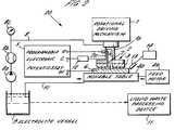
- FIG. 2schematically illustrates, in simplified cross-sectional form, an embodiment of an apparatus according to the present invention, comprising a CMP-type apparatus modified to perform EMP processing.
- apparatus 20comprises a rotational driving mechanism 1 for rotating shaft la, which shaft in turn rotates tool electrode 2 formed of an electrochemically inert metal or metal alloy.
- Tool electrode 2is disc-shaped and mounts on the lower surface thereof a liquid-permeable, non-conductive, polishing pad 3 .
- Rotational driving mechanism 1is adapted to provide a predetermined downwardly urging pressure of the polishing pad 3 during rotation.
- An abrasive slurry/liquid electrolyte supply 2a conduitis formed within the central elongated portion of tool electrode 2 and the center of polishing pad 3 and includes a plurality of radially extending channels formed within the lower pad surface for evenly supplying the liquid-permeable polishing pad 3 and the space therebelow with slurry/electrolyte.
- Tool electrode 2is electrically connected to the counter-electrode terminal C of programmable electronic potentiostat 5 and typically is negatively (i.e., cathodically) biased during polishing/planarization processing.
- Movable table 4amounting a workpiece 6 on its upper surface in facing relation to the lower surface of polishing pad 3 is disposed below the tool electrode 2 , and is reciprocated by means of feed motor 4b and associated mechanism, leftwardly and rightwardly as shown in the figure.
- At least the upper surface of workpiece 6 comprising a pattern of electrical, e.g., metal, conductors therein or thereonis electrically connected to the working electrode terminal W of potentiostat 5 and typically is positively (i.e., anodically) biased during polishing/planarization processing.
- a reference electrode 7typically formed of an inert metal, e.g., platinum (Pt), or of Ag/Agcl, is electrically connected to the reference electrode terminal R of potentiostat 5 and extends through the slurry/electrolyte supply conduit 2a of tool electrode 2 , whereby the exposed tip thereof is positioned in close proximity to the upper surface of workpiece 6 .
- Ptplatinum
- a slurry/electrolyte supply conduit 8is connected to a slurry/electrolyte supply vessel or reservoir 9 for supplying an oxidizer-free, abrasive particle-containing, slurry/electrolyte between the polishing pad 3 and the upper surface of workpiece 6 .
- a supply pump 8a , flow meter 8b , and pressure gage 8care disposed between supply conduit 8 and supply vessel 9 .
- the slurry/electrolyteis supplied from the supply vessel 9 by way of the supply conduit 8 and fed through the slurry/electrolyte supply conduit 2a to be between the polishing pad 3 and the upper surface of workpiece 6 , and is returned to supply vessel 9 by way of return conduit 10 .
- a slurry/liquid waste processing device 11is optionally provided for disposal of spent slurry/electrolyte after excessive accumulation therein of dissolved metal(s) from workpiece 6 .
- Electronic potentiostat 5is provided with internal or external programming means (not shown for illustrative simplicity), as are conventional in the art, for supplying any of a variety of desired anodic potential vs. time profiles to workpiece 6 .
- a programmable 2-electrode DC power supplycan be utilized in the event less precise control of the applied anodic voltage is acceptable.
- a coulometer 12can be provided in either the working or counter-electrode supply lines for determining an end-point of EMP processing, e.g., when a predetermined amount of current flow indicating a predetermined amount of metal dissolution, has occurred.
- a sensor 13positioned adjacent the upper, polished surface of workpiece 6 and operatively connected to a measuring device 14 may be utilized for determining an end-point of EMP by measuring and/or detecting a change in a physical (e.g., electrical) or optical property thereof.
- FIG. 3schematically illustrates, in simplified cross-sectional form, another embodiment of an EMP apparatus according to the present invention.
- Apparatus 40resembles known apparatus for performing CMP of workpiece substrates such as semiconductor wafers, and comprises, in pertinent part, a workpiece holder 21 connected at its underside to shaft 22 for rotation of a workpiece 23 (e.g., a semiconductor wafer having at least one electrical, i.e., metal, conductor formed in or on the upwardly facing surface 23' thereof) about a central axis 24 , while urging the upwardly facing workpiece surface 23' with force F 1 against the downwardly facing surface 25' of porous electrolyte applicator/polishing pad.
- a workpiece holder 21connected at its underside to shaft 22 for rotation of a workpiece 23 (e.g., a semiconductor wafer having at least one electrical, i.e., metal, conductor formed in or on the upwardly facing surface 23' thereof) about a central axis 24 , while urging
- Electrolyte applicator/polishing pad 25is adapted (by means not shown for illustrative simplicity) for rotating about a central axis 26 in a direction counter to that of workpiece holder 21 while urging downwardly facing surface 25' with force F 2 against upwardly facing workpiece surface 23' .
- Apparatus 40further includes a programmable electronic potentiostat 27 , of conventional type, the working electrode terminal W (typically of positive polarity) being operatively connected by line 28 to rotatable shaft 22 for establishing anodic electrochemical conditions at workpiece surface 23' .
- the counter-electrode terminal C(typically of negative polarity) of electronic potentiostat 27 is operatively connected by line 29 to electrochemically inert counter-electrode 30 located on the upwardly facing surface 25" of electrolyte applicator/polishing pad 25 , for establishing cathodic electrochemical conditions at the downwardly facing surface 30' thereof.
- the tip of a reference electrode 34is positioned in close proximity to the workpiece surface 23' in the narrow, electrolyte-filled space between the lower surface 25' of the applicator/polishing pad 25 and the workpiece upper surface 23' and is operatively connected to the reference electrode terminal R of potentiostat 27 via line 35 .
- Ptinert metal
- a spray of an oxidizer-free slurry/electrolyte 31 comprising abrasive particles of sufficiently small dimension as to pass freely through the porous electrolyte applicator/polishing pad 25is supplied to the upwardly facing surface 25" of the pad from slurry/electrolyte reservoir 32 by means of supply conduit 33 , for replenishing consumed slurry/electrolyte 31 and maintaining the pores of the electrolyte applicator/polishing 25 pad in a filled state.
- the embodiment of FIG. 3may employ a 2-electrode programmable DC power supply if diminished precision of anodic potential control is acceptable in a particular situation, thereby dispensing with the need for reference electrode 34 and its associated positioning means.
- a coulometermay be electrically positioned in either the working electrode or counter-electrode circuit for providing end-point indication, as in the earlier embodiment.
- a sensor and measuring means for determining a physical (e.g., electrical) or optical property of the polished surface for determining the end-point of EMP processingmay also be provided, as in the earlier embodiment.
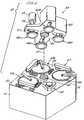
- FIGS. 4-6illustrated therein is yet another embodiment of an EMP apparatus according to the present invention, which apparatus is a of a multi-station type such as is employed in automated semiconductor manufacture.
- a multi-station CMP apparatus 50including a lower machine base 51 having an upper table surface 52 and a removable upper cover (not shown).
- upper table surface 52supports thereon a plurality of chemical-mechanical polishing stations 53a , 53b , and 53c and a transfer station 54 which serves for providing a plurality of functions, including, inter alia, receiving substrates from a loading apparatus (not shown for illustrative simplicity), washing the substrates, loading the substrates onto carrier heads, receiving polished substrates, and transferring the polished substrates back to the loading apparatus.
- a loading apparatusnot shown for illustrative simplicity
- Each polishing station 53a , 53b , and 53cincludes a rotatable platen 55 on which is mounted a polishing pad 56 and each of the polishing stations may further include an associated pad conditioner apparatus 57 for maintaining the condition of the respective polishing pad so that it will effectively polish a substrate pressed against it while rotating.
- Intermediate washing stations 58are positioned between neighboring polishing stations 53a , 53b , 53c and transfer station 54 for rinsing substrates as they pass from one polishing station to another.
- a rotatable multi-head carousel 59Positioned above the lower machine base 51 is a rotatable multi-head carousel 59 , supported by a center post 60 located on the upper table surface 52 and adapted for rotation about carousel axis 61 by means of a motor located within base 51 .
- the center post 60supports a carousel base plate 62 and associated cover 63 .
- the multi-head carousel 59includes a plurality of head systems 64 , illustratively four, i.e., 64a , 64b , 64c , and 64d .
- Three of the carrier head systemsmount thereon a substrate, and polish the respective surface thereof by pressing it against an opposing polishing pad 56 mounted on the platen 55 of polishing stations 53a , 53b , and 53c .
- One of the carrier head systemsreceives substrates from, and delivers substrates to, transfer station 54 .
- the four carrier head systems 64a-64dare mounted on the carousel base plate 62 at equidistant intervals about the carousel rotational axis 61 .
- Center post 60supports carousel base plate 62 and allows the carousel motor to rotate the carousel base plate 62 and to orbit the carrier head systems 64a-64d , and the substrates mounted thereon, about carousel axis 61 .
- Each of the carrier head systems 64a-64dincludes a polishing or carrier head (shown in more detail in FIG. 5), which carrier rotates about its own rotational axis via a respective motor 65 coupled to drive shaft 66 , and independently laterally oscillates in a radially extending slot 67 formed in the carousel base plate 62 .
- FIG. 5illustrates, in schematic, cross-sectional view, one of the carrier head systems 64a-64d in operative position facing a polishing pad 56 of a polishing station 53 for polishing/planarization of a wafer substrate 68 , which carrier head system is adapted for performing electrochemical-mechanical planarization (EMP) according to the present invention.
- EMPelectrochemical-mechanical planarization
- rotatable drive shaft or spindle 66is operatively connected to rotating polishing head assembly 69 comprising a circularly-shaped, inner mounting piece 70 having a narrow, shaft-like axially extending upper portion 71 connected to drive shaft 66 and a wide lower portion 72 having a non-conductive membrane 73 on its lower surface for mounting wafer substrate thereon, and an outer, annularly-shaped mounting piece 74 having an inwardly extending flange portion 75 at its upper end and an annularly-shaped retaining ring 76 at its lower end.
- the CMP apparatus 50is modified, as in the previous embodiments, to provide for controlled application of a time-varying electrochemical potential, e.g., a variable anodic potential, to wafer substrate 68 for performing EMP processing.
- a time-varying electrochemical potentiale.g., a variable anodic potential
- programmable electronic potentiostat 77having working (w), counter (c), and reference (r) electrode outputs is operatively connected to the polishing head assembly 69 by means of respective electrical leads 78 , brush-type electrical contactors 79 , and concentric contact rings 80 formed on the upper surface of the wide lower portion 72 of mounting piece 70 .
- Respective electrical leads connected to contact rings 80are connected to an annularly-shaped electrical contact located between insulative membrane 73 and the rear surface of wafer substrate 68 , inwardly of the wafer circumference, for permitting functioning of the wafer as a working (w) electrode, and to an alternating plurality of counter electrodes 81 (e.g., of an electrochemically inert, electrically conductive material such as Pt or C) and reference electrodes 82 (e.g., of Pt or Ag/AgCl) positioned in grooved recesses 83 formed in the lower surface of retaining ring 76 , as shown in greater detail in FIG. 6.
- counter electrodes 81e.g., of an electrochemically inert, electrically conductive material such as Pt or C
- reference electrodes 82e.g., of Pt or Ag/AgCl
- the reference electrodes 82may be dispensed with, if desired, and a 2-electrode programmable DC power supply utilized in place of the 3-electrode potentiostat 77 of the illustrated embodiment, provided reduced precision of control of anodic potential applied to the wafer substrate 68 is acceptable in a particular situation.
- a coulometermay be electrically positioned in either the working electrode or counter-electrode circuit for providing end-point indication/detection.
- a sensor and measuring means for determining a physical propertye.g., electrical resistance as determined by a conventional 4-contact probe device
- an optical property of the polished surfacee.g., reflectance as indicated by means of a conventional light source/photocell apparatus
- the present inventionis advantageously fully compatible with all aspects of conventional process technology, e.g., CMP processing of semiconductor wafers utilized in integrated circuit semiconductor device manufacture.
- inventive concept disclosed hereinmay be applied to CMP processing and apparatus therefor which do not employ abrasive slurries, e.g., where an abrasive or non-abrasive polishing/planarizing pad is employed in combination with an electrolytically conductive, non-abrasive particle-containing liquid.
Landscapes
- Engineering & Computer Science (AREA)
- Chemical & Material Sciences (AREA)
- Chemical Kinetics & Catalysis (AREA)
- Electrochemistry (AREA)
- Mechanical Engineering (AREA)
- Computer Hardware Design (AREA)
- General Physics & Mathematics (AREA)
- Manufacturing & Machinery (AREA)
- Condensed Matter Physics & Semiconductors (AREA)
- Microelectronics & Electronic Packaging (AREA)
- Power Engineering (AREA)
- Physics & Mathematics (AREA)
- Mechanical Treatment Of Semiconductor (AREA)
- Finish Polishing, Edge Sharpening, And Grinding By Specific Grinding Devices (AREA)
- Weting (AREA)
- Constituent Portions Of Griding Lathes, Driving, Sensing And Control (AREA)
- Electrical Discharge Machining, Electrochemical Machining, And Combined Machining (AREA)
Abstract
Description
The present invention relates to a method and apparatus forelectrochemically-assisted or -augmented mechanical planarization, i.e.,electrochemical-mechanical planarization ("EMP"), which method and apparatusenjoy particular utility in the manufacture of semiconductor integrated circuitdevices.
Chemical-mechanical polishing (CMP) techniques and apparatus thereforhave been developed for providing smooth topographies, particularly on thesurfaces of layers deposited on semiconductor substrates during integrated circuitmanufacture. In such instances, rough topography results when metal conductorlines are formed over a substrate containing device circuitry, e.g., inter-levelmetallization patterns comprising a plurality of electrically conductive lines whichmay,inter alia, serve to interconnect discrete devices formed within the substrate.The metal conductor lines are insulated from each other and from verticallyadjacent interconnection levels by thin layers of dielectric insulation material, and openings formed through the insulating layers provide electrical interconnectionand access between successive such interconnection levels. In fabricating suchtype devices including multiple interconnection and insulative layers, it isdesirable that the metallic and insulative layers have a smooth topography,inasmuch as it is very difficult to photolithographically image and pattern layersapplied to rough surfaces. CMP can also be employed for removing differentlayers of material from the surface of a semiconductor substrate, as for example,following via hole formation in an insulating layer, when a metallization layer isdeposited and then CMP is used to form planar metal via plugs embedded in theinsulating layer.
Briefly, CMP processes utilized in semiconductor device manufactureinvolve mounting a thin flat workpiece, e.g., a semiconductor wafer substrate, ona carrier or polishing head, with the surface to be polished being exposed. Thesubstrate surface is then urged against a wetted polishing surface, i.e., a rotatingpolishing pad, under controlled mechanical pressure, chemical, and temperatureconditions. In addition, the carrier head may rotate to provide additional motionbetween the substrate and polishing pad surfaces. A polishing slurry containing apolishing agent, such as alumina (Al2O3) or silica (SiO2) finely-dimensionedparticles is used as the abrasive material. Additionally, the polishing slurrycontains a number of chemicals, including pH adjusting and stabilizing agents, aswell as chemical oxidizing agents for chemically removing (i.e., etching) variouscomponents of the surface being planarized. The combination of mechanical andchemical removal of surface material during the polishing process results insuperior planarization of the polished surface, vis-à-vis other planarizationtechniques.
Slurries used for CMP can be divided into three categories, dependingupon their intended use: silicon (Si) polish slurries, oxide polish slurries, andmetal polish slurries. Si polish slurries are designed to polish and planarize bare Siwafers and are typically composed of very small (i.e., about 20 - 200 nm diameter) abrasive particles, e.g., of silica (SiO2), alumina (Al2O3), or ceria(CeO2), suspended in a water-based liquid at a somewhat basic pH provided by apH adjusting agent, typically a hydroxide-type base. Oxide polish slurries aredesigned to polish and planarize a dielectric layer on a wafer, typically a layer ofsilicon dioxide (Si02), and are similarly composed of very small abrasive particles(i.e., about 20 - 1000 run diameter) of, e.g., SiO2, Al2O3, or CeO2, suspended in awater-based liquid at a high (i.e., basic) pH.
Metals polish slurries are designed to polish and planarize conductivelayers on semiconductor wafer substrates. The conductive layers are typicallydeposited on a dielectric layer and typically comprise metals such as tungsten(W), titanium (Ti), aluminum (Al), copper (Cu), alloys thereof, semiconductorssuch as doped silicon (Si), doped polysilicon, and refractory metal silicides. Thedielectric layer typically contains openings ("vias") that are filled with theconductive material to provide a path through the dielectric layer to previouslydeposited layers. After the conductive layer is polished, only the conductivematerial filling the vias remains in the dielectric layer.
Metal polish slurries utilized for such CMP of vias typically include verysmall particles (i.e., about 20 - 1000 run diameter) of the above-mentionedabrasive materials, suspended in a water-based liquid. In contrast to the Si andoxide-type polishing slurries, the pH may be acidic (i.e., < 5) or neutral and isobtained and controlled by addition of acid(s) or salt(s) thereof. In addition to theorganic acid(s) or salt(s), metals polishing slurries include one or more oxidizingagents for assisting in metal dissolution and removal, typically selected fromhydrogen peroxide, potassium ferricyanide, ferric nitrate, or combinations thereof.
However, the combination of acidic or neutral pH and presence ofoxidizing agent(s), hereafter "oxidizer(s)", in CMP metals polishing slurries canresult in several disadvantages, drawbacks, and difficulties, including,inter alia:
U.S. Pat. 4,839,005 discloses a method and apparatus for providingmirror-smooth finishes to aluminum surfaces by applying a constant anodic potential to the surface via a passivation-type electrolyte solution, whilesimultaneously performing mechanical polishing thereof with an abrasive slurryor cloth. While such electrolytically-assisted polishing may dispense with therequirement for a chemical oxidizer in the polishing slurry or abrasive cloth, theapplication of a constant anodic potential renders the disclosed method/apparatusunsatisfactory for use in the planarization of workpieces comprisingsemiconductor wafers with surfaces having electrically conductive wirings, etc.,in that undesirable dishing would still occur during the late stage(s) ofplanarization due to excessive, electrochemically promoted anodic metaldissolution, as in the conventional methodology employing chemical oxidizingagent(s).
Accordingly, there exists a need for a simplified and reliable method andapparatus for performing planarization processing, particularly of semiconductorwafer substrates comprising surfaces including metallization patterns on or withina dielectric material layer, which method and apparatus are free of thedisadvantages and drawbacks associated with the conventional CMPmethodologies, and are fully compatible with the economic and productthroughput requirements of automated semiconductor manufacture processing.
The present invention addresses and solves the above-described problemsattendant upon the manufacture of integrated circuit semiconductor and otherelectrical and electronic devices according to conventional CMP methodologyutilizing abrasive slurries containing chemical oxidizer agent(s), and is fullycompatible with all other mechanical aspects of CMP-type planarizationprocessing.
An aspect of the present invention is an improved method of planarizingworkpiece surfaces comprising an electrically conductive material.
Another aspect of the present invention is an improved method ofplanarizing a workpiece surface by means of an electrochemical-mechanicalplanarization (EMP) process and apparatus utilizing an abrasive slurry free ofchemical oxidizing agent(s).
Yet another aspect of the present invention is an improved method ofcontrollably planarizing a workpiece surface.
Still another aspect of the present invention is an improved method ofcontrollably planarizing a semiconductor substrate surface comprising a pattern ofelectrical conductors.
A still further aspect of the present invention is improved apparatus forcontrollably performing EMP of at least one surface of at least one workpiece.
A yet another aspect of the present invention is improved apparatus forperforming EMP of a workpiece surface with an oxidizer-free abrasive slurry.
Additional aspects and other features of the present invention will be setforth in the description which follows and in part will become apparent to thosehaving ordinary skill in the art upon examination of the following or may belearned from the practice of the present invention. The advantages of the presentinvention may be realized and obtained as particularly pointed out in theappended claims.
According to one aspect of the present invention, the foregoing and otheradvantages are achieved in part by a method of planarizing a surface of aworkpiece by electrochemical-mechanical planarization (EMP), which methodcomprises the steps of:
In embodiments according to the present invention, step (c) comprisesperforming EMP by controllably applying a time-varying anodic potential to theat least one workpiece surface. In particular embodiments according to the presentinvention, step (c) comprises applying a first, higher anodic potential during aninitial stage of the EMP and applying a second, lower anodic potential at orduring a later stage of the EMP; or step (c) comprises reducing the first, higheranodic potential to the second, lower anodic potential during an intermediate stageof the EMP, e.g., continuously reducing the anodic potential during theintermediate stage; or step (c) comprises rapidly reducing the anodic potentialfrom the first, higher potential to the second, lower potential after a predeterminedinterval at the first, higher potential.
According to further embodiments of the present invention, step (c)comprises applying the time-varying electrochemical potential from a controllablyvariable DC power supply, e.g., an electronic potentiostat; and a further step (d)comprises monitoring the extent of the EMP of the at least one workpiece surfacein order to determine the end-point thereof. According to particular embodimentsof the present invention, step (d) comprises coulometrically monitoring the extentof EMP, or step (d) comprises monitoring a signal from a sensor utilized formeasuring a physical property (e.g., electrical resistance or conductance)) oroptical property (e.g., reflectance) of the at least one workpiece surface.
According to yet further embodiments of the present invention, step (a)comprises providing a semiconductor wafer substrate as the workpiece, thesemiconductor wafer substrate comprising the at least one workpiece surface andincluding a pattern of electrical conductors formed on or within a layer of adielectric material; and step (b) comprises supplying the CMP apparatus with an oxidizer-free, electrolytically conductive, abrasive slurry comprising finely-dimensionedabrasive particles and at least one pH adjusting agent.
According to still further embodiments according to the present invention,step (a) comprises providing a CMP apparatus having a non-abrasive polishingpad and step (b) comprises supplying the CMP apparatus with an oxidizer-free,electrolytically conductive fluid comprising an abrasive slurry comprising finely-dimensionedabrasive particles; or step (a) comprises providing a CMP apparatushaving an abrasive polishing pad and step (b) comprises supplying the CMPapparatus with an oxidizer-free, electrolytically conductive fluid comprising anon-abrasive liquid; or step (a) comprises providing a CMP apparatus having anon-abrasive polishing pad and step (b) comprises supplying the CMP apparatuswith an oxidizer-free, electrolytically conductive fluid comprising a non-abrasiveliquid.
According to another aspect of the present invention, apparatus forperforming electrochemical-mechanical planarization (EMP) of at least onesurface of at least one workpiece comprise:
In embodiments according to the present invention, the device (a) adaptedfor performing CMP of at least one workpiece surface comprises an abrasivepolishing pad or a non-abrasive polishing pad; power supply (b) comprises anelectronic potentiostat adapted for applying a time-varying, anodicelectrochemical potential to the at least one workpiece surface; and the apparatusfurther comprises a device (c) for monitoring the extent of EMP of the at least oneworkpiece surface for determining the end-point thereof. According to particularembodiments of the present invention, the monitoring device (c) comprises a coulometer or a sensor for providing a signal indicative of a physical (e.g.,electrical) or optical property of the at least one workpiece surface.
Additional advantages of the present invention will become readilyapparent to those skilled in the art from the following detailed description,wherein only the preferred embodiment of the present invention is shown anddescribed, simply by way of illustration of the best mode contemplated forcarrying out the method of the present invention. As will be described, the presentinvention is capable of other and different embodiments, and its several details arecapable of modification in various obvious respects, all without departing fromthe present invention. Accordingly, the drawing and description are to be regardedas illustrative in nature, and not as limitative.
The following detailed description of the embodiment of the presentinvention can best be understood when read in conjunction with the followingdrawings, wherein:
The present invention is based upon the discovery that electrochemical-mechanicalplanarization (EMP) processing of workpiece surfaces, e.g.,semiconductor wafer substrates having electrically conductive patterns formedtherein or thereon, such as are utilized in integrated semiconductor devicemanufacture, can be performed in chemical-mechanical polishing apparatushaving abrasive or non-abrasive polishing pads and appropriately modified toapply a time-varying electrochemical potential to the workpiece surface, i.e., ananodic potential, and wherein oxidizer-free fluids such as abrasive slurries or non-abrasiveliquids are utilized, thereby,inter alia, advantageously eliminatingproblems of dishing and corrosion as are commonly encountered during staticperiods and in the later stages of conventional CMP planarization processing.
Briefly stated, according to the present invention, instead of effectingmetals dissolution/removal by means of chemical oxidizer agent(s), an anodicelectrochemical potential is applied to the surface being polished, which surfaceincludes a pattern of metal conductors, and the abrasive slurry or non-abrasiveliquid supplied to the apparatus is free of chemical oxidizer(s). The applied anodicelectrochemical potential is advantageously controlled by means of aprogrammable electronic potentiostat, whereby potential control is easy andprecise. During the initial stage(s) of the polish, a relatively high anodic potentialis applied to the metal-bearing workpiece surface to promote relatively aggressive(i.e., high rate) oxidation/dissolution/removal of the metal pattern. Whenpolishing is at a later stage, e.g., when approaching an underlying barrier layer,such as of tantalum (Ta), the applied anodic potential is reduced to a levelproducing substantially less aggressive (i.e., low or negligibly low rate)oxidation/dissolution/removal of the metal features, thereby eliminating orsubstantially reducing static etching and resultant dishing, corrosion, and erosionas encountered with conventional CMP processing.
According to the present invention, the application of a time-varyinganodic electrochemical potential to the workpiece surface for assisting in metalsdissolution/removal, i.e., as a replacement for the chemical oxidizer agent(s)present in conventional CMP metals polishing slurries, entails a number ofadvantages vis-à-vis the latter, including the following:
Referring now to FIG. 1, illustrated therein, by way of illustration but notlimitation, are several examples of applied anodic potential vs. time profilessuitable for use in the present invention. However, given the present disclosureand objectives of the present invention, it is considered within the scope ofordinary variation to determine other profiles for use in a given application.Further, while the illustrated and other possible anodic voltage vs. time profilesare best obtained by means of a conventional 3-electrode (i.e., working,reference, and counter electrodes), programmable electronic potentiostat system, aprogrammable 2-electrode (i.e., working and counter electrodes) power supplymay be employed where less precise control of the applied anodic potential issatisfactory.
Curve A of FIG. 1 illustrates a case where a relatively high, constantanodic potential is first applied to the workpiece surface for a specific intervalduring the initial polishing stage in order to promote aggressive, i.e., high rate,metal oxidation/dissolution/removal as to reduce overall processing time andincrease product throughput, followed by a linear decrease in applied anodicpotential during an intermediate polishing stage to a preselected relatively lowanodic potential providing a low or negligible metals dissolution rate, followed inturn by maintenance of the relatively low anodic potential during the finalpolishing stage.
By contrast, curve B of FIG. 1 illustrates a case where the initial, relativelyhigh, anodic potential applied at the initial polishing phase is continuouslyreduced during the entire polishing interval to the relatively low level achievedduring the final polishing stage. Curve C of FIG. 1 illustrates yet another casewhere the initial, relatively high anodic potential is maintained constant for apredetermined interval and then rapidly reduced to the relatively low level for theremainder of the polishing process.
As should be readily apparent, a large number and variety of appliedanodic potential vs. time profiles are usable within the context and spirit of thepresent invention. Moreover, the specific voltage levels, intervals, rates ofdecrease, etc., are readily optimized by one of ordinary skill for use in a particularapplication, e.g., depending upon the particular metal(s) to be polished/planarizedand the thicknesses thereof.
FIG. 2 schematically illustrates, in simplified cross-sectional form, anembodiment of an apparatus according to the present invention, comprising aCMP-type apparatus modified to perform EMP processing. As illustrated,apparatus 20 comprises a rotational driving mechanism1 for rotating shaft la,which shaft in turn rotates tool electrode2 formed of an electrochemically inertmetal or metal alloy. Tool electrode2 is disc-shaped and mounts on the lowersurface thereof a liquid-permeable, non-conductive, polishing pad3. Rotationaldriving mechanism1 is adapted to provide a predetermined downwardly urgingpressure of the polishing pad3 during rotation. An abrasive slurry/liquidelectrolyte supply2a conduit is formed within the central elongated portion oftool electrode2 and the center of polishing pad3 and includes a plurality ofradially extending channels formed within the lower pad surface for evenlysupplying the liquid-permeable polishing pad3 and the space therebelow withslurry/electrolyte. Tool electrode2 is electrically connected to the counter-electrodeterminal C of programmable electronic potentiostat5 and typically isnegatively (i.e., cathodically) biased during polishing/planarization processing.
Movable table4a mounting aworkpiece 6 on its upper surface in facingrelation to the lower surface of polishing pad3 is disposed below the toolelectrode2, and is reciprocated by means of feed motor4b and associatedmechanism, leftwardly and rightwardly as shown in the figure. At least the uppersurface ofworkpiece 6 comprising a pattern of electrical, e.g., metal, conductorstherein or thereon is electrically connected to the working electrode terminal W ofpotentiostat5 and typically is positively (i.e., anodically) biased duringpolishing/planarization processing. A reference electrode7, typically formed ofan inert metal, e.g., platinum (Pt), or of Ag/Agcl, is electrically connected to thereference electrode terminal R of potentiostat5 and extends through theslurry/electrolyte supply conduit2a of tool electrode2, whereby the exposed tipthereof is positioned in close proximity to the upper surface ofworkpiece 6.
A slurry/electrolyte supply conduit8 is connected to a slurry/electrolytesupply vessel or reservoir9 for supplying an oxidizer-free, abrasive particle-containing,slurry/electrolyte between the polishing pad3 and the upper surface ofworkpiece 6. A supply pump8a, flow meter8b, and pressure gage8c aredisposed between supply conduit8 and supply vessel9. The slurry/electrolyte issupplied from the supply vessel9 by way of the supply conduit8 and fed throughthe slurry/electrolyte supply conduit2a to be between the polishing pad3 and theupper surface ofworkpiece 6, and is returned to supply vessel9 by way of returnconduit10. A slurry/liquid waste processing device11 is optionally provided fordisposal of spent slurry/electrolyte after excessive accumulation therein ofdissolved metal(s) fromworkpiece 6.
Electronic potentiostat5 is provided with internal or externalprogramming means (not shown for illustrative simplicity), as are conventional inthe art, for supplying any of a variety of desired anodic potential vs. time profilestoworkpiece 6. As previously indicated, a programmable 2-electrode DC powersupply can be utilized in the event less precise control of the applied anodicvoltage is acceptable. Moreover, acoulometer 12 can be provided in either the working or counter-electrode supply lines for determining an end-point of EMPprocessing, e.g., when a predetermined amount of current flow indicating apredetermined amount of metal dissolution, has occurred. Alternatively, asensor 13, positioned adjacent the upper, polished surface ofworkpiece 6 and operativelyconnected to a measuring device14 may be utilized for determining an end-pointof EMP by measuring and/or detecting a change in a physical (e.g., electrical) oroptical property thereof.
FIG. 3 schematically illustrates, in simplified cross-sectional form, anotherembodiment of an EMP apparatus according to the present invention.Apparatus 40 resembles known apparatus for performing CMP of workpiece substrates suchas semiconductor wafers, and comprises, in pertinent part, aworkpiece holder 21connected at its underside toshaft 22 for rotation of a workpiece23 (e.g., asemiconductor wafer having at least one electrical, i.e., metal, conductor formedin or on the upwardly facing surface23' thereof) about a central axis24, whileurging the upwardly facing workpiece surface23' with force F1 against thedownwardly facing surface25' of porous electrolyte applicator/polishing pad.Electrolyte applicator/polishing pad 25 is adapted (by means not shown forillustrative simplicity) for rotating about acentral axis 26 in a direction counter tothat ofworkpiece holder 21 while urging downwardly facing surface25' withforce F2 against upwardly facing workpiece surface23'.Apparatus 40 furtherincludes a programmableelectronic potentiostat 27, of conventional type, theworking electrode terminal W (typically of positive polarity) being operativelyconnected byline 28 torotatable shaft 22 for establishing anodic electrochemicalconditions at workpiece surface23'. The counter-electrode terminal C (typicallyof negative polarity) ofelectronic potentiostat 27 is operatively connected byline 29 to electrochemically inert counter-electrode30 located on the upwardly facingsurface 25" of electrolyte applicator/polishing pad 25, for establishing cathodicelectrochemical conditions at the downwardly facing surface30' thereof. In theillustrated embodiment, the tip of areference electrode 34, typically of an inert metal, e.g., Pt, is positioned in close proximity to the workpiece surface23' in thenarrow, electrolyte-filled space between the lower surface25' of theapplicator/polishing pad 25 and the workpiece upper surface23' and isoperatively connected to the reference electrode terminal R ofpotentiostat 27 vialine 35. However, it is within the ambit of the present invention to provide otherphysically configured arrangements for positioning the tip of the referenceelectrode in electrolyte in close proximity to the workpiece upper surface23'. Aspray of an oxidizer-free slurry/electrolyte31 comprising abrasive particles ofsufficiently small dimension as to pass freely through the porous electrolyteapplicator/polishing pad 25 is supplied to the upwardly facingsurface 25" of thepad from slurry/electrolyte reservoir 32 by means ofsupply conduit 33, forreplenishing consumed slurry/electrolyte31 and maintaining the pores of theelectrolyte applicator/polishing25 pad in a filled state.
As in the embodiment illustrated in FIG.2, the embodiment of FIG. 3 mayemploy a 2-electrode programmable DC power supply if diminished precision ofanodic potential control is acceptable in a particular situation, thereby dispensingwith the need forreference electrode 34 and its associated positioning means. Inaddition, a coulometer may be electrically positioned in either the workingelectrode or counter-electrode circuit for providing end-point indication, as in theearlier embodiment. Finally, a sensor and measuring means for determining aphysical (e.g., electrical) or optical property of the polished surface fordetermining the end-point of EMP processing may also be provided, as in theearlier embodiment.
Referring now to FIGS.4-6, illustrated therein is yet another embodimentof an EMP apparatus according to the present invention, which apparatus is a of amulti-station type such as is employed in automated semiconductor manufacture.With particular reference to FIG. 1, illustrated therein in schematic, explodedview, is a multi-station CMP apparatus50 including alower machine base 51having anupper table surface 52 and a removable upper cover (not shown). As shown,upper table surface 52 supports thereon a plurality of chemical-mechanicalpolishing stations transfer station 54 whichserves for providing a plurality of functions, including,inter alia, receivingsubstrates from a loading apparatus (not shown for illustrative simplicity),washing the substrates, loading the substrates onto carrier heads, receivingpolished substrates, and transferring the polished substrates back to the loadingapparatus.
Each polishingstation polishing pad 56 and each of the polishing stations mayfurther include an associatedpad conditioner apparatus 57 for maintaining thecondition of the respective polishing pad so that it will effectively polish asubstrate pressed against it while rotating.Intermediate washing stations 58 arepositioned between neighboring polishingstations transferstation 54 for rinsing substrates as they pass from one polishing station to another.
Positioned above thelower machine base 51 is a rotatable multi-headcarousel59, supported by a center post60 located on theupper table surface 52and adapted for rotation aboutcarousel axis 61 by means of a motor locatedwithinbase 51. The center post60 supports a carousel base plate62 andassociatedcover 63. The multi-head carousel59 includes a plurality ofheadsystems 64, illustratively four, i.e.,64a,64b,64c, and64d. Three of the carrierhead systems mount thereon a substrate, and polish the respective surface thereofby pressing it against an opposingpolishing pad 56 mounted on the platen55 ofpolishingstations transfer station 54.
Typically, the four carrier head systems64a-64d are mounted on thecarousel base plate62 at equidistant intervals about the carouselrotational axis 61. Center post60 supports carousel base plate62 and allows the carousel motorto rotate the carousel base plate62 and to orbit the carrier head systems64a-64d,and the substrates mounted thereon, aboutcarousel axis 61. Each of the carrier head systems64a-64d includes a polishing or carrier head (shown in more detailin FIG. 5), which carrier rotates about its own rotational axis via arespectivemotor 65 coupled to driveshaft 66, and independently laterally oscillates in aradially extending slot 67 formed in the carousel base plate62.
FIG. 5 illustrates, in schematic, cross-sectional view, one of the carrierhead systems64a-64d in operative position facing apolishing pad 56 of apolishing station53 for polishing/planarization of awafer substrate 68, whichcarrier head system is adapted for performing electrochemical-mechanicalplanarization (EMP) according to the present invention. As shown therein,rotatable drive shaft orspindle 66 is operatively connected to rotating polishinghead assembly 69 comprising a circularly-shaped, inner mounting piece70 havinga narrow, shaft-like axially extendingupper portion 71 connected to driveshaft 66and a wide lower portion 72 having anon-conductive membrane 73 on its lowersurface for mounting wafer substrate thereon, and an outer, annularly-shapedmounting piece74 having an inwardly extendingflange portion 75 at its upperend and an annularly-shapedretaining ring 76 at its lower end.
According to the present invention, the CMP apparatus50, as describedsupra, is modified, as in the previous embodiments, to provide for controlledapplication of a time-varying electrochemical potential, e.g., a variable anodicpotential, towafer substrate 68 for performing EMP processing. Accordingly,programmableelectronic potentiostat 77 having working (w), counter (c), andreference (r) electrode outputs is operatively connected to the polishingheadassembly 69 by means of respectiveelectrical leads 78, brush-typeelectricalcontactors 79, and concentric contact rings80 formed on the upper surface of thewide lower portion72 of mounting piece70. Respective electrical leadsconnected to contactrings 80 are connected to an annularly-shaped electricalcontact located betweeninsulative membrane 73 and the rear surface ofwafersubstrate 68, inwardly of the wafer circumference, for permitting functioning ofthe wafer as a working (w) electrode, and to an alternating plurality of counter electrodes81 (e.g., of an electrochemically inert, electrically conductive materialsuch as Pt or C) and reference electrodes82 (e.g., of Pt or Ag/AgCl) positionedingrooved recesses 83 formed in the lower surface of retainingring 76, as shownin greater detail in FIG. 6.
As in the previous embodiments, thereference electrodes 82 may bedispensed with, if desired, and a 2-electrode programmable DC power supplyutilized in place of the 3-electrode potentiostat 77 of the illustrated embodiment,provided reduced precision of control of anodic potential applied to thewafersubstrate 68 is acceptable in a particular situation. Moreover, as before, acoulometer may be electrically positioned in either the working electrode orcounter-electrode circuit for providing end-point indication/detection.Alternatively, a sensor and measuring means for determining a physical property(e.g., electrical resistance as determined by a conventional 4-contact probedevice) or an optical property of the polished surface (e.g., reflectance asindicated by means of a conventional light source/photocell apparatus) fordetermining the end-point of EMP processing may also be provided, as in thepreviously described embodiments.
A number of advantages are thus provided by the present invention,including, but not limited to, substantial reduction or elimination of undesirabledishing and erosion in planarization of semiconductor wafer surfaces comprisingelectrically conductive patterns, elimination of chemical oxidizers from wasteslurry streams, reduced cost, improved control of planarization, and increasedmanufacturing throughput for economic competitiveness. Moreover, the presentinvention is advantageously fully compatible with all aspects of conventionalprocess technology, e.g., CMP processing of semiconductor wafers utilized inintegrated circuit semiconductor device manufacture. In addition, the inventiveconcept disclosed herein may be applied to CMP processing and apparatustherefor which do not employ abrasive slurries, e.g., where an abrasive or non-abrasive polishing/planarizing pad is employed in combination with anelectrolytically conductive, non-abrasive particle-containing liquid.
In the previous descriptions, numerous specific details are set forth, suchas particular materials, structures, reactants, processes, etc., in order to provide athorough understanding of the present invention. However, it should berecognized that the present invention can be practiced without resorting to thedetails specifically set forth. For example, the present invention is applicable toplanarization of a variety of substrates, including, but not limited tosemiconductor wafers and electronic circuit board manufacture. In otherinstances, well-known processing structures and techniques have not beendescribed in detail in order not to unnecessarily obscure the present invention.
Only the preferred embodiments of the present invention are shown anddescribed herein. It is to be understood that the present invention is capable ofchanges and/or modifications within the scope of the inventive concept asexpressed herein.
Claims (25)
- A method of planarizing a surface of a workpieceby electrochemical-mechanical planarization (EMP),comprising the steps of:(a) providing a chemical-mechanical polishing(CMP) apparatus with at least one workpiece having atleast one surface to be planarized by EMP;(b) supplying said CMP apparatus with anelectrolytically conductive fluid free of chemicaloxidizing agent(s); and(c) planarizing the at least one workpiecesurface by EMP utilizing said CMP apparatus, saidplanarizing by EMP including applying a time-varyingelectrochemical potential to the at least oneworkpiece surface.
- A method as claimed in claim 1, wherein:
step (c) comprises performing said EMP bycontrollably applying a time varying anodic potentialto said at least one workpiece surface. - A method as claimed in claim 2, wherein:
step (c) comprises applying a first, higheranodic potential to said workpiece surface during aninitial stage of said EMP and applying a second, loweranodic potential to said workpiece surface at orduring a later stage of said EMP. - A method as claimed in claim 3, wherein:
step (c) comprises reducing said first, higheranodic potential to said second, lower anodicpotential during an intermediate stage of said EMP. - A method as claimed in claim 4, wherein:
step (c) comprises continuously reducing saidanodic potential during said intermediate stage. - A method as claimed in claim 3, wherein:
step (c) comprises rapidly reducing said anodicpotential from said first, higher potential to saidsecond, lower potential. - A method as claimed in any of claims 1 to 6,wherein:
step (c) comprises applying said time-varyingelectrochemical potential from a controllably variableDC power supply. - A method as claimed in claim 7, wherein:
step (c) comprises utilizing a programmableelectronic potentiostat. - A method as claimed in any of claims 1 to 8,further comprising the step of:
(d) monitoring the extent of said EMP of said atleast one workpiece surface in order to determine theend-point thereof. - A method as claimed in claim 9, wherein:
step (d) comprises coulometrically monitoring theextent of EMP. - A method as claimed in claim 9, wherein:
step (d) comprises monitoring a signal from asensor utilized for measuring a physical or opticalproperty of said at least one workpiece surface. - A method as claimed in any of claims 1 to 11,wherein:
step (a) comprises providing a semiconductorwafer substrate as said at least one workpiece, saidsemiconductor substrate comprising said at least oneworkpiece surface and including a pattern ofelectrical conductors formed on or within a layer of dielectric material. - A method as claimed in any of claims 1 to 12,wherein:step (a) comprises providing a CMP apparatushaving a non-abrasive polishing pad; andstep (b) comprises supplying the CMP apparatuswith an oxidizer-free, electrolytically conductivefluid comprises an abrasive slurry comprising finely-dimensionedabrasive particles.
- A method as claimed in claim 13, wherein:
step (b) comprises supplying the CMP apparatuswith an oxidizer-free, electrolytically conductivefluid comprising a non-abrasive liquid. - A method as claimed in any of claims 1 to 12,wherein:step (a) comprises providing a CMP apparatushaving an abrasive polishing pad; andstep (b) comprising supplying the CMP apparatuswith an oxidizer-free, electrolytically conductivefluid comprising an non-abrasive liquid
- An apparatus for performing electrochemical-mechanicalplanarization (EMP)of at least one surfaceof at least one workpiece, comprising:(a) a device adapted for performing chemical-mechanicalpolishing (CMP) of said at least oneworkpiece surface; and(b) a power supply connected to the CMPapparatus for providing a controllable, time-varyingDC electrochemical potential to the at least oneworkpiece surface for effecting EMP thereof.
- An apparatus as claimed in claim 16, wherein:
said power supply (b) comprises an electronic potentiostat adapted for applying a time-varyinganodic electrochemical potential to said at least oneworkpiece surface. - An apparatus as claimed in claim 16 or claim 17,comprising:
(c) a device for monitoring the extent of saidEMP of said at least one workpiece surface fordetermining the end-point thereof. - An apparatus as claimed in claim 18, wherein:
said monitoring device (c) comprises acoulometer. - An apparatus as claimed in claim 18, wherein:
said monitoring device (c) comprises a sensor forproviding a signal indicative of a physical or opticalproperty of said at least one workpiece surface. - An apparatus as claimed in claim 20, wherein saidsensor comprises an optical property sensor.
- An apparatus as claimed in claim 20, wherein saidsensor comprises an electrical property sensor.
- An apparatus as claimed in any of claims 16 to22, wherein:
said CMP device (c) comprises an abrasive or non-abrasivepolishing pad. - An apparatus as claimed in claim 23, wherein:
said device (c) further comprises means forsupplying an electrolytically conductive fluid into aspace between said polishing pad and said at least oneworkpiece surface. - An apparatus as claimed in claim 24, wherein:
said electrolytically conductive fluid comprisesan abrasive particle-containing slurry or a non-abrasiveliquid.
Applications Claiming Priority (2)
| Application Number | Priority Date | Filing Date | Title |
|---|---|---|---|
| US09/450,937US6379223B1 (en) | 1999-11-29 | 1999-11-29 | Method and apparatus for electrochemical-mechanical planarization |
| US450937 | 1999-11-29 |
Publications (2)
| Publication Number | Publication Date |
|---|---|
| EP1103346A2true EP1103346A2 (en) | 2001-05-30 |
| EP1103346A3 EP1103346A3 (en) | 2001-11-21 |
Family
ID=23790134
Family Applications (1)
| Application Number | Title | Priority Date | Filing Date |
|---|---|---|---|
| EP00310358AWithdrawnEP1103346A3 (en) | 1999-11-29 | 2000-11-22 | Method and apparatus for electrochemical-mechanical planarization |
Country Status (3)
| Country | Link |
|---|---|
| US (2) | US6379223B1 (en) |
| EP (1) | EP1103346A3 (en) |
| JP (1) | JP2001196335A (en) |
Cited By (26)
| Publication number | Priority date | Publication date | Assignee | Title |
|---|---|---|---|---|
| WO2002078903A3 (en)* | 2001-03-30 | 2003-03-20 | Nutool Inc | Method and apparatus for avoiding particle accumulation during an electrochemical process |
| WO2003043780A3 (en)* | 2001-11-20 | 2003-08-28 | Rensselaer Polytech Inst | Method for polishing a substrate surface |
| WO2003072672A1 (en)* | 2002-02-26 | 2003-09-04 | Applied Materials, Inc. | Method and composition for polishing a substrate |
| WO2003050867A3 (en)* | 2001-12-07 | 2003-11-13 | Nutool Inc | Planarity detection methods and apparatus for electrochemical mechanical processing systems |
| WO2003092945A1 (en)* | 2002-04-30 | 2003-11-13 | Sony Corporation | Electrolytic polishing liquid, electrolytic polishing method and method for fabricating semiconductor device |
| WO2003098673A1 (en)* | 2002-05-21 | 2003-11-27 | Sony Corporation | Polishing method and polishing system, and method for fabricating semiconductor device |
| US6802955B2 (en) | 2002-01-11 | 2004-10-12 | Speedfam-Ipec Corporation | Method and apparatus for the electrochemical deposition and planarization of a material on a workpiece surface |
| US6811680B2 (en) | 2001-03-14 | 2004-11-02 | Applied Materials Inc. | Planarization of substrates using electrochemical mechanical polishing |
| US6837983B2 (en)* | 2002-01-22 | 2005-01-04 | Applied Materials, Inc. | Endpoint detection for electro chemical mechanical polishing and electropolishing processes |
| US6863797B2 (en) | 2001-12-21 | 2005-03-08 | Applied Materials, Inc. | Electrolyte with good planarization capability, high removal rate and smooth surface finish for electrochemically controlled copper CMP |
| WO2004111314A3 (en)* | 2003-03-18 | 2005-06-09 | Applied Materials Inc | Algorithm for real-time process control of electro-polishing |
| WO2004078411A3 (en)* | 2003-03-04 | 2005-07-21 | Applied Materials Inc | Method and apparatus for local polishing control |
| US6991526B2 (en) | 2002-09-16 | 2006-01-31 | Applied Materials, Inc. | Control of removal profile in electrochemically assisted CMP |
| US7070475B2 (en) | 2002-09-16 | 2006-07-04 | Applied Materials | Process control in electrochemically assisted planarization |
| US7128825B2 (en) | 2001-03-14 | 2006-10-31 | Applied Materials, Inc. | Method and composition for polishing a substrate |
| US7141155B2 (en) | 2003-02-18 | 2006-11-28 | Parker-Hannifin Corporation | Polishing article for electro-chemical mechanical polishing |
| US7160432B2 (en) | 2001-03-14 | 2007-01-09 | Applied Materials, Inc. | Method and composition for polishing a substrate |
| US7232514B2 (en)* | 2001-03-14 | 2007-06-19 | Applied Materials, Inc. | Method and composition for polishing a substrate |
| US7422982B2 (en) | 2006-07-07 | 2008-09-09 | Applied Materials, Inc. | Method and apparatus for electroprocessing a substrate with edge profile control |
| US7655565B2 (en) | 2005-01-26 | 2010-02-02 | Applied Materials, Inc. | Electroprocessing profile control |
| EP1470576A4 (en)* | 2002-01-31 | 2010-03-03 | Ebara Corp | Electrolytic processing apparatus and substrate processing apparatus and method |
| US7790015B2 (en) | 2002-09-16 | 2010-09-07 | Applied Materials, Inc. | Endpoint for electroprocessing |
| CN102407482A (en)* | 2011-04-29 | 2012-04-11 | 上海华力微电子有限公司 | Method for adjusting metal grinding speed and overcoming defects in grinding process |
| CN104470681A (en)* | 2012-06-21 | 2015-03-25 | 国立大学法人鹿儿岛大学 | Observation camera |
| CN111716235A (en)* | 2020-06-19 | 2020-09-29 | 上海交通大学 | Heat-assisted chemical-mechanical composite abrasive flow polishing device and method |
| WO2024109607A1 (en)* | 2022-11-23 | 2024-05-30 | 杭州众硅电子科技有限公司 | Conductive-type polishing head fixing device and conductive-type polishing head system |
Families Citing this family (117)
| Publication number | Priority date | Publication date | Assignee | Title |
|---|---|---|---|---|
| US7686935B2 (en)* | 1998-10-26 | 2010-03-30 | Novellus Systems, Inc. | Pad-assisted electropolishing |
| US7425250B2 (en)* | 1998-12-01 | 2008-09-16 | Novellus Systems, Inc. | Electrochemical mechanical processing apparatus |
| US7427337B2 (en)* | 1998-12-01 | 2008-09-23 | Novellus Systems, Inc. | System for electropolishing and electrochemical mechanical polishing |
| US7578923B2 (en)* | 1998-12-01 | 2009-08-25 | Novellus Systems, Inc. | Electropolishing system and process |
| US6497800B1 (en) | 2000-03-17 | 2002-12-24 | Nutool Inc. | Device providing electrical contact to the surface of a semiconductor workpiece during metal plating |
| US6464571B2 (en) | 1998-12-01 | 2002-10-15 | Nutool, Inc. | Polishing apparatus and method with belt drive system adapted to extend the lifetime of a refreshing polishing belt provided therein |
| US6299741B1 (en)* | 1999-11-29 | 2001-10-09 | Applied Materials, Inc. | Advanced electrolytic polish (AEP) assisted metal wafer planarization method and apparatus |
| US6630059B1 (en)* | 2000-01-14 | 2003-10-07 | Nutool, Inc. | Workpeice proximity plating apparatus |
| US7059948B2 (en)* | 2000-12-22 | 2006-06-13 | Applied Materials | Articles for polishing semiconductor substrates |
| US7670468B2 (en)* | 2000-02-17 | 2010-03-02 | Applied Materials, Inc. | Contact assembly and method for electrochemical mechanical processing |
| US7678245B2 (en) | 2000-02-17 | 2010-03-16 | Applied Materials, Inc. | Method and apparatus for electrochemical mechanical processing |
| US7066800B2 (en)* | 2000-02-17 | 2006-06-27 | Applied Materials Inc. | Conductive polishing article for electrochemical mechanical polishing |
| US7125477B2 (en)* | 2000-02-17 | 2006-10-24 | Applied Materials, Inc. | Contacts for electrochemical processing |
| US7374644B2 (en)* | 2000-02-17 | 2008-05-20 | Applied Materials, Inc. | Conductive polishing article for electrochemical mechanical polishing |
| US6962524B2 (en)* | 2000-02-17 | 2005-11-08 | Applied Materials, Inc. | Conductive polishing article for electrochemical mechanical polishing |
| US7077721B2 (en) | 2000-02-17 | 2006-07-18 | Applied Materials, Inc. | Pad assembly for electrochemical mechanical processing |
| US20050092621A1 (en)* | 2000-02-17 | 2005-05-05 | Yongqi Hu | Composite pad assembly for electrochemical mechanical processing (ECMP) |
| US20040182721A1 (en)* | 2003-03-18 | 2004-09-23 | Applied Materials, Inc. | Process control in electro-chemical mechanical polishing |
| US20040020789A1 (en)* | 2000-02-17 | 2004-02-05 | Applied Materials, Inc. | Conductive polishing article for electrochemical mechanical polishing |
| US20080156657A1 (en)* | 2000-02-17 | 2008-07-03 | Butterfield Paul D | Conductive polishing article for electrochemical mechanical polishing |
| US7303462B2 (en)* | 2000-02-17 | 2007-12-04 | Applied Materials, Inc. | Edge bead removal by an electro polishing process |
| US7303662B2 (en)* | 2000-02-17 | 2007-12-04 | Applied Materials, Inc. | Contacts for electrochemical processing |
| US6991528B2 (en)* | 2000-02-17 | 2006-01-31 | Applied Materials, Inc. | Conductive polishing article for electrochemical mechanical polishing |
| US7029365B2 (en) | 2000-02-17 | 2006-04-18 | Applied Materials Inc. | Pad assembly for electrochemical mechanical processing |
| US6979248B2 (en)* | 2002-05-07 | 2005-12-27 | Applied Materials, Inc. | Conductive polishing article for electrochemical mechanical polishing |
| US6797623B2 (en)* | 2000-03-09 | 2004-09-28 | Sony Corporation | Methods of producing and polishing semiconductor device and polishing apparatus |
| US6852208B2 (en) | 2000-03-17 | 2005-02-08 | Nutool, Inc. | Method and apparatus for full surface electrotreating of a wafer |
| KR100502330B1 (en)* | 2000-04-29 | 2005-07-20 | 삼성에스디아이 주식회사 | Base panel having a partition and plasma display palel utilizing the same |
| US7192335B2 (en) | 2002-08-29 | 2007-03-20 | Micron Technology, Inc. | Method and apparatus for chemically, mechanically, and/or electrolytically removing material from microelectronic substrates |
| US7074113B1 (en)* | 2000-08-30 | 2006-07-11 | Micron Technology, Inc. | Methods and apparatus for removing conductive material from a microelectronic substrate |
| US7094131B2 (en) | 2000-08-30 | 2006-08-22 | Micron Technology, Inc. | Microelectronic substrate having conductive material with blunt cornered apertures, and associated methods for removing conductive material |
| US7134934B2 (en)* | 2000-08-30 | 2006-11-14 | Micron Technology, Inc. | Methods and apparatus for electrically detecting characteristics of a microelectronic substrate and/or polishing medium |
| US7153410B2 (en)* | 2000-08-30 | 2006-12-26 | Micron Technology, Inc. | Methods and apparatus for electrochemical-mechanical processing of microelectronic workpieces |
| US7160176B2 (en) | 2000-08-30 | 2007-01-09 | Micron Technology, Inc. | Methods and apparatus for electrically and/or chemically-mechanically removing conductive material from a microelectronic substrate |
| US7153195B2 (en) | 2000-08-30 | 2006-12-26 | Micron Technology, Inc. | Methods and apparatus for selectively removing conductive material from a microelectronic substrate |
| US7112121B2 (en)* | 2000-08-30 | 2006-09-26 | Micron Technology, Inc. | Methods and apparatus for electrical, mechanical and/or chemical removal of conductive material from a microelectronic substrate |
| US7129160B2 (en)* | 2002-08-29 | 2006-10-31 | Micron Technology, Inc. | Method for simultaneously removing multiple conductive materials from microelectronic substrates |
| US7078308B2 (en)* | 2002-08-29 | 2006-07-18 | Micron Technology, Inc. | Method and apparatus for removing adjacent conductive and nonconductive materials of a microelectronic substrate |
| US7220166B2 (en)* | 2000-08-30 | 2007-05-22 | Micron Technology, Inc. | Methods and apparatus for electromechanically and/or electrochemically-mechanically removing conductive material from a microelectronic substrate |
| US6896776B2 (en) | 2000-12-18 | 2005-05-24 | Applied Materials Inc. | Method and apparatus for electro-chemical processing |
| US6736952B2 (en)* | 2001-02-12 | 2004-05-18 | Speedfam-Ipec Corporation | Method and apparatus for electrochemical planarization of a workpiece |
| US7582564B2 (en)* | 2001-03-14 | 2009-09-01 | Applied Materials, Inc. | Process and composition for conductive material removal by electrochemical mechanical polishing |
| US7323416B2 (en)* | 2001-03-14 | 2008-01-29 | Applied Materials, Inc. | Method and composition for polishing a substrate |
| US20070290166A1 (en)* | 2001-03-14 | 2007-12-20 | Liu Feng Q | Method and composition for polishing a substrate |
| US7344432B2 (en)* | 2001-04-24 | 2008-03-18 | Applied Materials, Inc. | Conductive pad with ion exchange membrane for electrochemical mechanical polishing |
| US7137879B2 (en)* | 2001-04-24 | 2006-11-21 | Applied Materials, Inc. | Conductive polishing article for electrochemical mechanical polishing |
| US7638030B2 (en)* | 2001-06-18 | 2009-12-29 | Ebara Corporation | Electrolytic processing apparatus and electrolytic processing method |
| US6953389B2 (en)* | 2001-08-09 | 2005-10-11 | Cheil Industries, Inc. | Metal CMP slurry compositions that favor mechanical removal of oxides with reduced susceptibility to micro-scratching |
| TW591089B (en)* | 2001-08-09 | 2004-06-11 | Cheil Ind Inc | Slurry composition for use in chemical mechanical polishing of metal wiring |
| US20030060145A1 (en)* | 2001-08-23 | 2003-03-27 | Li Youlin J. | Multi-step polishing system and process of using same |
| JP3807295B2 (en)* | 2001-11-30 | 2006-08-09 | ソニー株式会社 | Polishing method |
| WO2003054255A1 (en)* | 2001-12-13 | 2003-07-03 | Ebara Corporation | Electrolytic processing apparatus and method |
| JP3941573B2 (en)* | 2002-04-24 | 2007-07-04 | 宇部興産株式会社 | Method for manufacturing flexible double-sided substrate |
| US20030201185A1 (en)* | 2002-04-29 | 2003-10-30 | Applied Materials, Inc. | In-situ pre-clean for electroplating process |
| US20050194681A1 (en)* | 2002-05-07 | 2005-09-08 | Yongqi Hu | Conductive pad with high abrasion |
| US20030209523A1 (en)* | 2002-05-09 | 2003-11-13 | Applied Materials, Inc. | Planarization by chemical polishing for ULSI applications |
| KR20030091824A (en)* | 2002-05-28 | 2003-12-03 | 쉬플리 캄파니, 엘.엘.씨. | Process of producing printed circuit boards and the circuit boards formed thereby |
| US7842434B2 (en)* | 2005-06-15 | 2010-11-30 | Ati Properties, Inc. | Interconnects for solid oxide fuel cells and ferritic stainless steels adapted for use with solid oxide fuel cells |
| US7981561B2 (en)* | 2005-06-15 | 2011-07-19 | Ati Properties, Inc. | Interconnects for solid oxide fuel cells and ferritic stainless steels adapted for use with solid oxide fuel cells |
| US8158057B2 (en)* | 2005-06-15 | 2012-04-17 | Ati Properties, Inc. | Interconnects for solid oxide fuel cells and ferritic stainless steels adapted for use with solid oxide fuel cells |
| US20040072445A1 (en)* | 2002-07-11 | 2004-04-15 | Applied Materials, Inc. | Effective method to improve surface finish in electrochemically assisted CMP |
| US7021993B2 (en)* | 2002-07-19 | 2006-04-04 | Cabot Microelectronics Corporation | Method of polishing a substrate with a polishing system containing conducting polymer |
| US6811474B2 (en) | 2002-07-19 | 2004-11-02 | Cabot Microelectronics Corporation | Polishing composition containing conducting polymer |
| JP4205914B2 (en)* | 2002-08-27 | 2009-01-07 | 株式会社ルネサステクノロジ | Semiconductor device manufacturing method and manufacturing apparatus |
| JP2004327561A (en)* | 2003-04-22 | 2004-11-18 | Ebara Corp | Substrate processing method and device thereof |
| JP2004356117A (en)* | 2003-05-26 | 2004-12-16 | Ebara Corp | Method and apparatus for processing substrate |
| US7390429B2 (en)* | 2003-06-06 | 2008-06-24 | Applied Materials, Inc. | Method and composition for electrochemical mechanical polishing processing |
| US20040259479A1 (en)* | 2003-06-23 | 2004-12-23 | Cabot Microelectronics Corporation | Polishing pad for electrochemical-mechanical polishing |
| US20050016861A1 (en)* | 2003-07-24 | 2005-01-27 | Thomas Laursen | Method for planarizing a work piece |
| US6848977B1 (en) | 2003-08-29 | 2005-02-01 | Rohm And Haas Electronic Materials Cmp Holdings, Inc. | Polishing pad for electrochemical mechanical polishing |
| US7112122B2 (en)* | 2003-09-17 | 2006-09-26 | Micron Technology, Inc. | Methods and apparatus for removing conductive material from a microelectronic substrate |
| US20050121141A1 (en)* | 2003-11-13 | 2005-06-09 | Manens Antoine P. | Real time process control for a polishing process |
| US7186164B2 (en)* | 2003-12-03 | 2007-03-06 | Applied Materials, Inc. | Processing pad assembly with zone control |
| US7255810B2 (en)* | 2004-01-09 | 2007-08-14 | Cabot Microelectronics Corporation | Polishing system comprising a highly branched polymer |
| US20050178666A1 (en)* | 2004-01-13 | 2005-08-18 | Applied Materials, Inc. | Methods for fabrication of a polishing article |
| US7390744B2 (en)* | 2004-01-29 | 2008-06-24 | Applied Materials, Inc. | Method and composition for polishing a substrate |
| US20060021974A1 (en)* | 2004-01-29 | 2006-02-02 | Applied Materials, Inc. | Method and composition for polishing a substrate |
| US7153777B2 (en)* | 2004-02-20 | 2006-12-26 | Micron Technology, Inc. | Methods and apparatuses for electrochemical-mechanical polishing |
| US7648622B2 (en) | 2004-02-27 | 2010-01-19 | Novellus Systems, Inc. | System and method for electrochemical mechanical polishing |
| US7125324B2 (en)* | 2004-03-09 | 2006-10-24 | 3M Innovative Properties Company | Insulated pad conditioner and method of using same |
| US20060287078A1 (en)* | 2004-04-22 | 2006-12-21 | Smolucha Walter E | Identifying components of a casino game |
| US7608173B2 (en)* | 2004-12-02 | 2009-10-27 | Applied Materials, Inc. | Biased retaining ring |
| US7276743B2 (en)* | 2004-05-13 | 2007-10-02 | Applied Materials, Inc. | Retaining ring with conductive portion |
| US20050263407A1 (en)* | 2004-05-28 | 2005-12-01 | Cabot Microelectronics Corporation | Electrochemical-mechanical polishing composition and method for using the same |
| US20060030156A1 (en)* | 2004-08-05 | 2006-02-09 | Applied Materials, Inc. | Abrasive conductive polishing article for electrochemical mechanical polishing |
| US20060043534A1 (en)* | 2004-08-26 | 2006-03-02 | Kirby Kyle K | Microfeature dies with porous regions, and associated methods and systems |
| US7566391B2 (en)* | 2004-09-01 | 2009-07-28 | Micron Technology, Inc. | Methods and systems for removing materials from microfeature workpieces with organic and/or non-aqueous electrolytic media |
| US7084064B2 (en)* | 2004-09-14 | 2006-08-01 | Applied Materials, Inc. | Full sequence metal and barrier layer electrochemical mechanical processing |
| WO2006039436A2 (en)* | 2004-10-01 | 2006-04-13 | Applied Materials, Inc. | Pad design for electrochemical mechanical polishing |
| US7520968B2 (en)* | 2004-10-05 | 2009-04-21 | Applied Materials, Inc. | Conductive pad design modification for better wafer-pad contact |
| US20060096179A1 (en)* | 2004-11-05 | 2006-05-11 | Cabot Microelectronics Corporation | CMP composition containing surface-modified abrasive particles |
| US20060169674A1 (en)* | 2005-01-28 | 2006-08-03 | Daxin Mao | Method and composition for polishing a substrate |
| US20060196778A1 (en)* | 2005-01-28 | 2006-09-07 | Renhe Jia | Tungsten electroprocessing |
| US7497938B2 (en)* | 2005-03-22 | 2009-03-03 | Cabot Microelectronics Corporation | Tribo-chronoamperometry as a tool for CMP application |
| US7311856B2 (en)* | 2005-03-30 | 2007-12-25 | Cabot Microelectronics Corporation | Polymeric inhibitors for enhanced planarization |
| US7427340B2 (en)* | 2005-04-08 | 2008-09-23 | Applied Materials, Inc. | Conductive pad |
| US20060249394A1 (en)* | 2005-05-05 | 2006-11-09 | Applied Materials, Inc. | Process and composition for electrochemical mechanical polishing |
| US20060249395A1 (en)* | 2005-05-05 | 2006-11-09 | Applied Material, Inc. | Process and composition for electrochemical mechanical polishing |
| US8070933B2 (en)* | 2005-05-06 | 2011-12-06 | Thielenhaus Microfinishing Corp. | Electrolytic microfinishing of metallic workpieces |
| US7998335B2 (en)* | 2005-06-13 | 2011-08-16 | Cabot Microelectronics Corporation | Controlled electrochemical polishing method |
| US20070062815A1 (en)* | 2005-09-19 | 2007-03-22 | Applied Materials, Inc. | Method for stabilized polishing process |
| US20070108066A1 (en)* | 2005-10-28 | 2007-05-17 | Applied Materials, Inc. | Voltage mode current control |
| US20070153453A1 (en)* | 2006-01-05 | 2007-07-05 | Applied Materials, Inc. | Fully conductive pad for electrochemical mechanical processing |
| US20070187258A1 (en)* | 2006-02-15 | 2007-08-16 | Tianbao Du | Method for electrochemically polishing a conductive material on a substrate |
| US20070218587A1 (en)* | 2006-03-07 | 2007-09-20 | Applied Materials, Inc. | Soft conductive polymer processing pad and method for fabricating the same |
| US20070235344A1 (en)* | 2006-04-06 | 2007-10-11 | Applied Materials, Inc. | Process for high copper removal rate with good planarization and surface finish |
| US20070251832A1 (en)* | 2006-04-27 | 2007-11-01 | Applied Materials, Inc. | Method and apparatus for electrochemical mechanical polishing of cu with higher liner velocity for better surface finish and higher removal rate during clearance |
| US20070254485A1 (en)* | 2006-04-28 | 2007-11-01 | Daxin Mao | Abrasive composition for electrochemical mechanical polishing |
| US7820051B2 (en)* | 2007-02-23 | 2010-10-26 | International Business Machines Corporation | Recycling of electrochemical-mechanical planarization (ECMP) slurries/electrolytes |
| US8012000B2 (en)* | 2007-04-02 | 2011-09-06 | Applied Materials, Inc. | Extended pad life for ECMP and barrier removal |
| US20080293343A1 (en)* | 2007-05-22 | 2008-11-27 | Yuchun Wang | Pad with shallow cells for electrochemical mechanical processing |
| US20090061741A1 (en)* | 2007-09-04 | 2009-03-05 | Zhihong Wang | Ecmp polishing sequence to improve planarity and defect performance |
| DE102009046750B4 (en)* | 2008-12-31 | 2019-02-14 | Globalfoundries Dresden Module One Limited Liability Company & Co. Kg | Electrochemical planarization system with improved electrolyte flow |
| US9227294B2 (en)* | 2013-12-31 | 2016-01-05 | Taiwan Semiconductor Manufacturing Company Ltd. | Apparatus and method for chemical mechanical polishing |
| US9676075B2 (en)* | 2015-06-12 | 2017-06-13 | Globalfoundries Inc. | Methods and structures for achieving target resistance post CMP using in-situ resistance measurements |
| US11389923B2 (en) | 2020-03-12 | 2022-07-19 | Bruker Nano, Inc. | Chemical-mechanical polishing system with a potentiostat and pulsed-force applied to a workpiece |
| US12090600B2 (en) | 2022-06-06 | 2024-09-17 | Applied Materials, Inc. | Face-up wafer electrochemical planarization apparatus |
Family Cites Families (51)
| Publication number | Priority date | Publication date | Assignee | Title |
|---|---|---|---|---|
| CH629542A5 (en) | 1976-09-01 | 1982-04-30 | Inoue Japax Res | METHOD AND DEVICE FOR GALVANIC MATERIAL DEPOSITION. |
| JPS5337543A (en) | 1976-09-20 | 1978-04-06 | Nippon Electric Co | Bump plating method |
| US4396467A (en) | 1980-10-27 | 1983-08-02 | General Electric Company | Periodic reverse current pulsing to form uniformly sized feed through conductors |
| US4466864A (en) | 1983-12-16 | 1984-08-21 | At&T Technologies, Inc. | Methods of and apparatus for electroplating preselected surface regions of electrical articles |
| US4869971A (en) | 1986-05-22 | 1989-09-26 | Nee Chin Cheng | Multilayer pulsed-current electrodeposition process |
| US4789437A (en) | 1986-07-11 | 1988-12-06 | University Of Hong Kong | Pulse electroplating process |
| JPS63288620A (en) | 1987-05-22 | 1988-11-25 | Kobe Steel Ltd | Electrolytic compound supermirror machining method for aluminum |
| CH678156A5 (en) | 1989-03-20 | 1991-08-15 | Exnii Metallorezh Stankov | |
| US5256565A (en) | 1989-05-08 | 1993-10-26 | The United States Of America As Represented By The United States Department Of Energy | Electrochemical planarization |
| US5039381A (en) | 1989-05-25 | 1991-08-13 | Mullarkey Edward J | Method of electroplating a precious metal on a semiconductor device, integrated circuit or the like |
| JP2745725B2 (en) | 1989-10-04 | 1998-04-28 | 旭硝子株式会社 | Electrolytic polishing / grinding method and apparatus |
| US5081421A (en)* | 1990-05-01 | 1992-01-14 | At&T Bell Laboratories | In situ monitoring technique and apparatus for chemical/mechanical planarization endpoint detection |
| US5114548A (en) | 1990-08-09 | 1992-05-19 | Extrude Hone Corporation | Orbital electrochemical machining |
| US5096550A (en) | 1990-10-15 | 1992-03-17 | The United States Of America As Represented By The United States Department Of Energy | Method and apparatus for spatially uniform electropolishing and electrolytic etching |
| US5141602A (en) | 1991-06-18 | 1992-08-25 | International Business Machines Corporation | High-productivity method and apparatus for making customized interconnections |
| US5217586A (en) | 1992-01-09 | 1993-06-08 | International Business Machines Corporation | Electrochemical tool for uniform metal removal during electropolishing |
| JP2875680B2 (en) | 1992-03-17 | 1999-03-31 | 株式会社東芝 | Method for filling or coating micropores or microdents on substrate surface |
| US5340370A (en) | 1993-11-03 | 1994-08-23 | Intel Corporation | Slurries for chemical mechanical polishing |
| JP2845163B2 (en) | 1994-10-27 | 1999-01-13 | 日本電気株式会社 | Plasma processing method and apparatus |
| US5522965A (en) | 1994-12-12 | 1996-06-04 | Texas Instruments Incorporated | Compact system and method for chemical-mechanical polishing utilizing energy coupled to the polishing pad/water interface |
| US5683538A (en) | 1994-12-23 | 1997-11-04 | International Business Machines Corporation | Control of etch selectivity |
| DE69632490T2 (en)* | 1995-03-28 | 2005-05-12 | Applied Materials, Inc., Santa Clara | Method and device for in-situ control and determination of the end of chemical mechanical grading |
| US5637185A (en)* | 1995-03-30 | 1997-06-10 | Rensselaer Polytechnic Institute | Systems for performing chemical mechanical planarization and process for conducting same |
| JP3529902B2 (en)* | 1995-07-04 | 2004-05-24 | 富士通株式会社 | Method for manufacturing semiconductor device |
| US5738574A (en) | 1995-10-27 | 1998-04-14 | Applied Materials, Inc. | Continuous processing system for chemical mechanical polishing |
| US5637031A (en) | 1996-06-07 | 1997-06-10 | Industrial Technology Research Institute | Electrochemical simulator for chemical-mechanical polishing (CMP) |
| US5664990A (en) | 1996-07-29 | 1997-09-09 | Integrated Process Equipment Corp. | Slurry recycling in CMP apparatus |
| US5846398A (en)* | 1996-08-23 | 1998-12-08 | Sematech, Inc. | CMP slurry measurement and control technique |
| US5972792A (en)* | 1996-10-18 | 1999-10-26 | Micron Technology, Inc. | Method for chemical-mechanical planarization of a substrate on a fixed-abrasive polishing pad |
| US5807165A (en) | 1997-03-26 | 1998-09-15 | International Business Machines Corporation | Method of electrochemical mechanical planarization |
| US5911619A (en)* | 1997-03-26 | 1999-06-15 | International Business Machines Corporation | Apparatus for electrochemical mechanical planarization |
| EP1015669B1 (en) | 1997-04-04 | 2010-11-17 | University Of Southern California | Electroplating method for forming a multilayer structure |
| MY125856A (en) | 1997-04-30 | 2006-08-30 | Minnesota Mining & Mfg | Method of planarizing the upper surface of a semiconductor wafer |
| US5972192A (en) | 1997-07-23 | 1999-10-26 | Advanced Micro Devices, Inc. | Pulse electroplating copper or copper alloys |
| US6010964A (en)* | 1997-08-20 | 2000-01-04 | Micron Technology, Inc. | Wafer surface treatment methods and systems using electrocapillarity |
| JP3255095B2 (en)* | 1997-09-30 | 2002-02-12 | 日本電気株式会社 | Polishing liquid and polishing method |
| WO1999026758A1 (en) | 1997-11-25 | 1999-06-03 | John Hopkins University | Electrochemical-control of abrasive polishing and machining rates |
| US6004880A (en) | 1998-02-20 | 1999-12-21 | Lsi Logic Corporation | Method of single step damascene process for deposition and global planarization |
| US6261433B1 (en) | 1998-04-21 | 2001-07-17 | Applied Materials, Inc. | Electro-chemical deposition system and method of electroplating on substrates |
| US5897426A (en)* | 1998-04-24 | 1999-04-27 | Applied Materials, Inc. | Chemical mechanical polishing with multiple polishing pads |
| US6143155A (en) | 1998-06-11 | 2000-11-07 | Speedfam Ipec Corp. | Method for simultaneous non-contact electrochemical plating and planarizing of semiconductor wafers using a bipiolar electrode assembly |
| US6248222B1 (en) | 1998-09-08 | 2001-06-19 | Acm Research, Inc. | Methods and apparatus for holding and positioning semiconductor workpieces during electropolishing and/or electroplating of the workpieces |
| US6056864A (en) | 1998-10-13 | 2000-05-02 | Advanced Micro Devices, Inc. | Electropolishing copper film to enhance CMP throughput |
| US6203684B1 (en) | 1998-10-14 | 2001-03-20 | Faraday Technology Marketing Group, Llc | Pulse reverse electrodeposition for metallization and planarization of a semiconductor substrates |
| US6176992B1 (en) | 1998-11-03 | 2001-01-23 | Nutool, Inc. | Method and apparatus for electro-chemical mechanical deposition |
| US6258220B1 (en) | 1998-11-30 | 2001-07-10 | Applied Materials, Inc. | Electro-chemical deposition system |
| US6328872B1 (en) | 1999-04-03 | 2001-12-11 | Nutool, Inc. | Method and apparatus for plating and polishing a semiconductor substrate |
| US6066030A (en)* | 1999-03-04 | 2000-05-23 | International Business Machines Corporation | Electroetch and chemical mechanical polishing equipment |
| US6328632B1 (en)* | 1999-08-31 | 2001-12-11 | Micron Technology, Inc. | Polishing pads and planarizing machines for mechanical and/or chemical-mechanical planarization of microelectronic substrate assemblies |
| JP4513145B2 (en) | 1999-09-07 | 2010-07-28 | ソニー株式会社 | Semiconductor device manufacturing method and polishing method |
| US6299741B1 (en) | 1999-11-29 | 2001-10-09 | Applied Materials, Inc. | Advanced electrolytic polish (AEP) assisted metal wafer planarization method and apparatus |
- 1999
- 1999-11-29USUS09/450,937patent/US6379223B1/ennot_activeExpired - Fee Related
- 2000
- 2000-11-22EPEP00310358Apatent/EP1103346A3/ennot_activeWithdrawn
- 2000-11-29JPJP2000363230Apatent/JP2001196335A/enactivePending
- 2002
- 2002-03-14USUS10/097,496patent/US6739951B2/ennot_activeExpired - Fee Related
Cited By (39)
| Publication number | Priority date | Publication date | Assignee | Title |
|---|---|---|---|---|
| US6936154B2 (en) | 2000-12-15 | 2005-08-30 | Asm Nutool, Inc. | Planarity detection methods and apparatus for electrochemical mechanical processing systems |
| US7232514B2 (en)* | 2001-03-14 | 2007-06-19 | Applied Materials, Inc. | Method and composition for polishing a substrate |
| US7160432B2 (en) | 2001-03-14 | 2007-01-09 | Applied Materials, Inc. | Method and composition for polishing a substrate |
| US7128825B2 (en) | 2001-03-14 | 2006-10-31 | Applied Materials, Inc. | Method and composition for polishing a substrate |
| US6811680B2 (en) | 2001-03-14 | 2004-11-02 | Applied Materials Inc. | Planarization of substrates using electrochemical mechanical polishing |
| US6932896B2 (en) | 2001-03-30 | 2005-08-23 | Nutool, Inc. | Method and apparatus for avoiding particle accumulation in electrodeposition |
| WO2002078903A3 (en)* | 2001-03-30 | 2003-03-20 | Nutool Inc | Method and apparatus for avoiding particle accumulation during an electrochemical process |
| WO2003043780A3 (en)* | 2001-11-20 | 2003-08-28 | Rensselaer Polytech Inst | Method for polishing a substrate surface |
| US7323414B2 (en) | 2001-11-20 | 2008-01-29 | Crystal Is, Inc. | Method for polishing a substrate surface |
| US7037838B2 (en) | 2001-11-20 | 2006-05-02 | Rensselaer Polytechnic Institute | Method for polishing a substrate surface |
| WO2003050867A3 (en)* | 2001-12-07 | 2003-11-13 | Nutool Inc | Planarity detection methods and apparatus for electrochemical mechanical processing systems |
| US6863797B2 (en) | 2001-12-21 | 2005-03-08 | Applied Materials, Inc. | Electrolyte with good planarization capability, high removal rate and smooth surface finish for electrochemically controlled copper CMP |
| US7229535B2 (en) | 2001-12-21 | 2007-06-12 | Applied Materials, Inc. | Hydrogen bubble reduction on the cathode using double-cell designs |
| US6802955B2 (en) | 2002-01-11 | 2004-10-12 | Speedfam-Ipec Corporation | Method and apparatus for the electrochemical deposition and planarization of a material on a workpiece surface |
| CN100425404C (en)* | 2002-01-22 | 2008-10-15 | 应用材料股份有限公司 | Electrochemical mechanical polishing system and method for detecting polishing endpoint |
| US6837983B2 (en)* | 2002-01-22 | 2005-01-04 | Applied Materials, Inc. | Endpoint detection for electro chemical mechanical polishing and electropolishing processes |
| EP1470576A4 (en)* | 2002-01-31 | 2010-03-03 | Ebara Corp | Electrolytic processing apparatus and substrate processing apparatus and method |
| WO2003072672A1 (en)* | 2002-02-26 | 2003-09-04 | Applied Materials, Inc. | Method and composition for polishing a substrate |
| WO2003092945A1 (en)* | 2002-04-30 | 2003-11-13 | Sony Corporation | Electrolytic polishing liquid, electrolytic polishing method and method for fabricating semiconductor device |
| WO2003098673A1 (en)* | 2002-05-21 | 2003-11-27 | Sony Corporation | Polishing method and polishing system, and method for fabricating semiconductor device |
| US7790015B2 (en) | 2002-09-16 | 2010-09-07 | Applied Materials, Inc. | Endpoint for electroprocessing |
| US7070475B2 (en) | 2002-09-16 | 2006-07-04 | Applied Materials | Process control in electrochemically assisted planarization |
| US7294038B2 (en) | 2002-09-16 | 2007-11-13 | Applied Materials, Inc. | Process control in electrochemically assisted planarization |
| US6991526B2 (en) | 2002-09-16 | 2006-01-31 | Applied Materials, Inc. | Control of removal profile in electrochemically assisted CMP |
| US7628905B2 (en) | 2002-09-16 | 2009-12-08 | Applied Materials, Inc. | Algorithm for real-time process control of electro-polishing |
| US7112270B2 (en)* | 2002-09-16 | 2006-09-26 | Applied Materials, Inc. | Algorithm for real-time process control of electro-polishing |
| US7141155B2 (en) | 2003-02-18 | 2006-11-28 | Parker-Hannifin Corporation | Polishing article for electro-chemical mechanical polishing |
| WO2004078411A3 (en)* | 2003-03-04 | 2005-07-21 | Applied Materials Inc | Method and apparatus for local polishing control |
| US7842169B2 (en) | 2003-03-04 | 2010-11-30 | Applied Materials, Inc. | Method and apparatus for local polishing control |
| WO2004111314A3 (en)* | 2003-03-18 | 2005-06-09 | Applied Materials Inc | Algorithm for real-time process control of electro-polishing |
| US7655565B2 (en) | 2005-01-26 | 2010-02-02 | Applied Materials, Inc. | Electroprocessing profile control |
| US7709382B2 (en) | 2005-01-26 | 2010-05-04 | Applied Materials, Inc. | Electroprocessing profile control |
| US7422982B2 (en) | 2006-07-07 | 2008-09-09 | Applied Materials, Inc. | Method and apparatus for electroprocessing a substrate with edge profile control |
| CN102407482A (en)* | 2011-04-29 | 2012-04-11 | 上海华力微电子有限公司 | Method for adjusting metal grinding speed and overcoming defects in grinding process |
| CN104470681A (en)* | 2012-06-21 | 2015-03-25 | 国立大学法人鹿儿岛大学 | Observation camera |
| EP2865489A4 (en)* | 2012-06-21 | 2016-05-11 | Kagoshima University Nat University Corp | OBSERVATION AND PHOTOGRAPHY APPARATUS |
| US9804067B2 (en) | 2012-06-21 | 2017-10-31 | Kagoshima University, National University Corporation | Observation and photography apparatus |
| CN111716235A (en)* | 2020-06-19 | 2020-09-29 | 上海交通大学 | Heat-assisted chemical-mechanical composite abrasive flow polishing device and method |
| WO2024109607A1 (en)* | 2022-11-23 | 2024-05-30 | 杭州众硅电子科技有限公司 | Conductive-type polishing head fixing device and conductive-type polishing head system |
Also Published As
| Publication number | Publication date |
|---|---|
| US20020111121A1 (en) | 2002-08-15 |
| US6739951B2 (en) | 2004-05-25 |
| US6379223B1 (en) | 2002-04-30 |
| EP1103346A3 (en) | 2001-11-21 |
| JP2001196335A (en) | 2001-07-19 |
Similar Documents
| Publication | Publication Date | Title |
|---|---|---|
| US6739951B2 (en) | Method and apparatus for electrochemical-mechanical planarization | |
| US7588677B2 (en) | Methods and apparatus for electrical, mechanical and/or chemical removal of conductive material from a microelectronic substrate | |
| US5637185A (en) | Systems for performing chemical mechanical planarization and process for conducting same | |
| KR100780257B1 (en) | Polishing method, polishing apparatus, plating method, and plating apparatus | |
| CN100425404C (en) | Electrochemical mechanical polishing system and method for detecting polishing endpoint | |
| US6592742B2 (en) | Electrochemically assisted chemical polish | |
| US6440295B1 (en) | Method for electropolishing metal on semiconductor devices | |
| US5637031A (en) | Electrochemical simulator for chemical-mechanical polishing (CMP) | |
| US6066030A (en) | Electroetch and chemical mechanical polishing equipment | |
| US6893328B2 (en) | Conductive polishing pad with anode and cathode | |
| US6299741B1 (en) | Advanced electrolytic polish (AEP) assisted metal wafer planarization method and apparatus | |
| JP4446271B2 (en) | Method and apparatus for electrically, mechanically and / or chemically removing a conductive material from a microelectronic substrate | |
| KR100720849B1 (en) | Method and apparatus for electrochemical-mechanical processing of microelectronic workpieces | |
| US20050173259A1 (en) | Endpoint system for electro-chemical mechanical polishing | |
| US6720263B2 (en) | Planarization of metal layers on a semiconductor wafer through non-contact de-plating and control with endpoint detection | |
| US20080188162A1 (en) | Electrochemical mechanical polishing apparatus conditioning method, and conditioning solution | |
| US20040072445A1 (en) | Effective method to improve surface finish in electrochemically assisted CMP | |
| KR20050005389A (en) | Polishing Method and Polishing System, and Method for Fabricating Semiconductor Device | |
| US6863794B2 (en) | Method and apparatus for forming metal layers | |
| CN100413037C (en) | Method and apparatus for electrically, mechanically and/or chemically removing conductive material from microelectronic substrates | |
| KR100611470B1 (en) | Chemical Mechanical Grinding Device with Polishing Endpoint Detection | |
| JP2005142594A (en) | Method and apparatus for controlling film thickness |
Legal Events
| Date | Code | Title | Description |
|---|---|---|---|
| PUAI | Public reference made under article 153(3) epc to a published international application that has entered the european phase | Free format text:ORIGINAL CODE: 0009012 | |
| AK | Designated contracting states | Kind code of ref document:A2 Designated state(s):AT BE CH CY DE DK ES FI FR GB GR IE IT LI LU MC NL PT SE TR | |
| AX | Request for extension of the european patent | Free format text:AL;LT;LV;MK;RO;SI | |
| PUAL | Search report despatched | Free format text:ORIGINAL CODE: 0009013 | |
| AK | Designated contracting states | Kind code of ref document:A3 Designated state(s):AT BE CH CY DE DK ES FI FR GB GR IE IT LI LU MC NL PT SE TR | |
| AX | Request for extension of the european patent | Free format text:AL;LT;LV;MK;RO;SI | |
| AKX | Designation fees paid | ||
| REG | Reference to a national code | Ref country code:DE Ref legal event code:8566 | |
| STAA | Information on the status of an ep patent application or granted ep patent | Free format text:STATUS: THE APPLICATION IS DEEMED TO BE WITHDRAWN | |
| 18D | Application deemed to be withdrawn | Effective date:20020522 |