EP1103226B1 - Transverse connector - Google Patents
Transverse connectorDownload PDFInfo
- Publication number
- EP1103226B1 EP1103226B1EP00122129AEP00122129AEP1103226B1EP 1103226 B1EP1103226 B1EP 1103226B1EP 00122129 AEP00122129 AEP 00122129AEP 00122129 AEP00122129 AEP 00122129AEP 1103226 B1EP1103226 B1EP 1103226B1
- Authority
- EP
- European Patent Office
- Prior art keywords
- clamping
- rod
- connector according
- traverse
- opening
- Prior art date
- Legal status (The legal status is an assumption and is not a legal conclusion. Google has not performed a legal analysis and makes no representation as to the accuracy of the status listed.)
- Expired - Lifetime
Links
- RTAQQCXQSZGOHL-UHFFFAOYSA-NTitaniumChemical compound[Ti]RTAQQCXQSZGOHL-UHFFFAOYSA-N0.000claims1
- 229910001220stainless steelInorganic materials0.000claims1
- 239000010935stainless steelSubstances0.000claims1
- 229910052719titaniumInorganic materials0.000claims1
- 239000010936titaniumSubstances0.000claims1
- 210000000988bone and boneAnatomy0.000description20
- 238000003780insertionMethods0.000description6
- 230000037431insertionEffects0.000description6
- 208000000875Spinal CurvaturesDiseases0.000description2
- 230000005540biological transmissionEffects0.000description1
- 238000012937correctionMethods0.000description1
- 238000013461designMethods0.000description1
- 238000011161developmentMethods0.000description1
- 238000001356surgical procedureMethods0.000description1
Images
Classifications
- A—HUMAN NECESSITIES
- A61—MEDICAL OR VETERINARY SCIENCE; HYGIENE
- A61B—DIAGNOSIS; SURGERY; IDENTIFICATION
- A61B17/00—Surgical instruments, devices or methods
- A61B17/56—Surgical instruments or methods for treatment of bones or joints; Devices specially adapted therefor
- A61B17/58—Surgical instruments or methods for treatment of bones or joints; Devices specially adapted therefor for osteosynthesis, e.g. bone plates, screws or setting implements
- A61B17/68—Internal fixation devices, including fasteners and spinal fixators, even if a part thereof projects from the skin
- A61B17/70—Spinal positioners or stabilisers, e.g. stabilisers comprising fluid filler in an implant
- A61B17/7049—Connectors, not bearing on the vertebrae, for linking longitudinal elements together
- A—HUMAN NECESSITIES
- A61—MEDICAL OR VETERINARY SCIENCE; HYGIENE
- A61B—DIAGNOSIS; SURGERY; IDENTIFICATION
- A61B17/00—Surgical instruments, devices or methods
- A61B2017/00831—Material properties
- A61B2017/00858—Material properties high friction or non-slip
Definitions
- the inventionrelates to a cross connector for osteosynthesis with the features of the preamble of claim 1.
- spinal curvaturesare treated by connecting and manipulating a plurality of vertebrae via a fixation rod.
- pedicle screwsare screwed into the vertebrae or placed on the vertebrae bone plates, in which the fixation rod or optionally also a plurality of fixation rods are used.
- the fixation rod or optionally also a plurality of fixation rodsare used.
- a plurality of fixation rodsmust generally be used, which are placed against each other.
- the inventionis therefore based on the object to provide a cross connector with which extremely curved spine can be corrected and is easy to handle.
- the cross connector according to the inventionnow makes it possible to use fixation rods which are less bent, even in the case of extremely curved spinal columns, the fixing rods being connected to the bone screws or bone plates and thus to the vertebrae via the transverse connector according to the invention, if a direct connection of the fixation rod on the bone screws or bone plates is not possible.
- the transverse connector according to the inventiontherefore, the correction forces can be transmitted safely and without play from the fixing rod to the corresponding vertebrae.
- the clamping lidhas a the rod-shaped portion of the cross connector encompassing strap. In this way, the clamping lid is held captive. In addition, the clamping and holding forces of the clamping cover are transmitted to the rod-shaped section via the bracket.
- the clamping sectionhas an opening receiving the fixing rod and this opening is provided with an open-edged slot.
- the opening of the fixing rodis passed and held by the fact that the cross-section of the opening is reduced after insertion of the fixing rod. This is usually done by screwing in a screw which reduces the slit and thereby jams the fixation rod in the receiving opening.
- a fixing screwis screwed into the clamping section, which acts directly on the fixing rod and holds it.
- Such clamping screwsare usually designed as set screws.
- the clamping lidhas a part of the receiving opening for the fixing rod.
- Such a configuration of the clamping portionhas the significant advantage that the Fixing rod can be relatively easily inserted into the receiving opening and placed only after the insertion or insertion of the fixation of the terminal cover and thereby the receiving opening is closed.
- the clamping lidis preferably mounted pivotably on the rod-shaped portion. By unfolding the fixation can be relatively easily removed and by closing the clamping lid, the receiving opening, as already mentioned, closed after insertion of the fixation.
- bracketis angled out of the plane of the clamping cover substantially at 90 ° and engages around the rod-shaped portion orthogonal to its longitudinal axis.
- This embodiment of the bracketallows on the one hand, the pivoting or unfolding of the terminal cover, on the other hand, an optimal introduction of force and mounting the terminal cover on the rod-shaped section.
- the brackethas a bearing forming a shoulder which is supported on an abutment of the other part of the clamping portion.
- the bearing with abutment and on the other handa clamping screw on opposite sides of the receiving opening for the fixing rod are arranged.
- On the side of the bearing with an abutmentis also the bracket that engages around the rod-shaped section. This design ensures that even high forces from the fixing rod can be easily introduced into the cross connector, without causing a change in position of the fixing rod in the clamping section.
- the rod-shaped portionhas a surface structure, in particular with in Provided longitudinally extending grooves.
- the receiving opening for the fixing rod on its inner surfaceat least partially provided with a surface structure, in particular extending in the longitudinal direction of the opening grooves. This surface structure prevents a change in position of the component in the associated clamping element.
- Other surface structuressuch as a corrugation, a threaded structure, etc., are also conceivable.
- the diameter of the rod-shaped portioncorresponds to the diameter of the receiving opening for the fixation rod.
- a simplification of the surgical procedureis achieved in that the clamping portion is provided with a screw fastened captive. There is no longer the risk that after insertion of the cross connector, but before the final jamming of the fixing rod parts of the cross connector get lost.
- the screw with which the clamping lid is attachedis always held captive on the terminal cover.
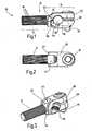
- FIG. 1shows a preferred embodiment of a cross connector 10 according to the invention.
- This cross connector 10is formed by a rod-shaped portion 12 and a clamping portion 14.
- the transverse connector 10is fastened, for example, to a bone screw (not shown) or to a bone plate (not shown).
- the cross section of the rod-shaped section 12corresponds to Essentially the cross-section of a fixation rod (not shown) that corrects for spinal curvatures.
- This rod-shaped portion 12has a round cross-section with on the outside in the longitudinal direction extending grooves 16, which constitute an anti-rotation.
- the clamping portion 14is constructed in two parts and has a first part 18 which is integrally connected to the rod-shaped portion 12.
- the second partis designed as a clamping cover 20 and pivotally mounted on the rod-shaped portion 12.
- the clamping lid 20which is particularly clear from Fig. 3 can be seen, a rod-shaped portion 12 encompassing bracket 22 which is angled out of the plane of the terminal cover 20 arcuate 90 ° and with its the terminal cover 20 remote end 24 is substantially orthogonal to the longitudinal axis of the rod-shaped portion 12 is.
- the clamping cover 20 and the first part 18 of the clamping portion 14form a receiving opening 26 which is provided with an open-edge slot 28.
- the receiving opening 26 of the (not shown) fixing rodis inserted and secured by jamming.
- the jammingtakes place in that a clamping screw 30, which is held captive in the clamping cover 20, in a corresponding threaded opening in the first part 18 is screwed.
- the clamping lid 20is clamped onto the fixing rod.
- the clamping cover 12pivots about a pivot bearing 32, which is formed by a shoulder 34 and an abutment 36.
- the receiving opening 26in the axial direction extending longitudinal grooves 38 which are provided on a part of the inner circumference of the receiving opening 26.
- the rod-shaped portion 12pivots in a kidney-shaped opening 40 surrounded by the bracket 22.
- the fixing rodcan now be easily inserted into the open receiving opening 26.
- the fixationis done by closing the clamping cover 20 and attaching the clamping screw 30 on the first part 18th
- the clamping portion 14is in one piece designed, ie the clamping cover 20 integrally formed on the first part 18.
- the receiving opening 26is thereby tapered and held therein a clamping rod by the clamping portion 14 is elastically deformed by screwing the clamping screw 30.
- the cross connector 10must be slid onto the fixation rod before it is fixed to the bone screws or bone plates.
Landscapes
- Health & Medical Sciences (AREA)
- Orthopedic Medicine & Surgery (AREA)
- Life Sciences & Earth Sciences (AREA)
- Neurology (AREA)
- Surgery (AREA)
- Heart & Thoracic Surgery (AREA)
- Engineering & Computer Science (AREA)
- Biomedical Technology (AREA)
- Nuclear Medicine, Radiotherapy & Molecular Imaging (AREA)
- Medical Informatics (AREA)
- Molecular Biology (AREA)
- Animal Behavior & Ethology (AREA)
- General Health & Medical Sciences (AREA)
- Public Health (AREA)
- Veterinary Medicine (AREA)
- Surgical Instruments (AREA)
- Prostheses (AREA)
Description
Translated fromGermanDie Erfindung betrifft einen Querverbinder für die Osteosynthese mit den Merkmalen des Oberbegriffs des Anspruchs 1.The invention relates to a cross connector for osteosynthesis with the features of the preamble of claim 1.
Es ist bekannt, dass Wirbelsäulenverkrümmungen dadurch behandelt werden, dass mehrere Wirbel über einen Fixierstab miteinander verbunden und dadurch lagekorrigiert werden. Hierfür werden in die Wirbel Pedikelschrauben eingedreht bzw. auf die Wirbel Knochenplatten aufgesetzt, in welche der Fixierstab oder ggf. auch mehrere Fixierstäbe eingesetzt werden. Bei extremen Wirbelsäulenverkrümmungen kommt es mitunter jedoch vor, dass die Krümmung des Fixierstabes nicht ausreicht, um die Wirbel bzw. die in den Wirbel eingeschraubten Knochenschrauben bzw. aufgesetzten Wirbelplatten an den Fixierstab anzubinden. Für derartige Wirbelsäulenverkrümmungen müssen in der Regel mehrere Fixierstäbe verwendet werden, die aneinandergesetzt werden. Dies führt jedoch dazu, dass in die einzelnen Wirbel mehrere Knochenschrauben eingedreht werden müssen, was mitunter zu Problemen führt, da die Festigkeit der Wirbel darunter leidet.It is known that spinal curvatures are treated by connecting and manipulating a plurality of vertebrae via a fixation rod. For this purpose, pedicle screws are screwed into the vertebrae or placed on the vertebrae bone plates, in which the fixation rod or optionally also a plurality of fixation rods are used. In extreme spine curvatures, however, it sometimes happens that the curvature of the fixation is insufficient to connect the vertebrae or screwed into the vertebrae bone screws or attached vertebral plates to the fixation. For such spine curvatures, a plurality of fixation rods must generally be used, which are placed against each other. However, this leads to the fact that several bone screws must be screwed into the individual vertebrae, which sometimes leads to problems because the strength of the vertebra suffers.
Aus der EP-A-0 737 448, die den nächstkommenden Stand der Technik darstellt, ist ein Querverbinder bekannt, bei dem der Klemmabschnitt mit einem Klemmdeckel verschlossen wird, der Klemmdeckel ein loses Bauteil darstellt und deshalb die Gefahr besteht, dass er bei der Operation verloren geht. Die US-A-5,562,663 zeigt einen ähnlich gestalteten Klemmabschnitt mit Klemmdeckel. Die FR-A-2,697,743 offenbart einen Querverbinder mit einem Aufnahmeauge für einen Querstab, der mittels radial einzudrehender Schrauben fixiert wird. Diese Art der Fixierung lässt keine große Kraftübertragung zu.From EP-A-0 737 448, which represents the closest prior art, a transverse connector is known in which the clamping portion is closed with a clamping lid, the clamping lid is a loose component and therefore the There is a risk that he will be lost during the operation. US-A-5,562,663 shows a similarly shaped clamping section with clamping lid. FR-A-2,697,743 discloses a cross connector having a receiving rod for a crossbar which is fixed by means of screws to be screwed in radially. This type of fixation does not allow much power transmission.
Der Erfindung liegt daher die Aufgabe zugrunde, einen Querverbinder bereitzustellen, mit dem auch extrem gekrümmte Wirbelsäulen korrigiert werden können und der einfach zu handhaben ist.The invention is therefore based on the object to provide a cross connector with which extremely curved spine can be corrected and is easy to handle.
Diese Aufgabe wird erfindungsgemäß mit einem Querverbinder gelöst, der die Merkmale des Anspruchs 1 aufweist.This object is achieved with a cross connector having the features of claim 1.
Mit dem erfindungsgemäßen Querverbinder besteht nun die Möglichkeit, auch bei extrem gekrümmten Wirbelsäulen Fixierstäbe zu verwenden, die weniger gebogen sind, wobei die Fixierstäbe über den erfindungsgemäßen Querverbinder mit den Knochenschrauben bzw. Knochenplatten und somit mit den Wirbeln verbunden werden, wenn eine direkte Anbindung des Fixierstabes an den Knochenschrauben bzw. Knochenplatten nicht möglich ist. Durch den erfindungsgemäßen Querverbinder können also die Korrekturkräfte sicher und spielfrei vom Fixierstab auf die entsprechenden Wirbel übertragen werden. Über den stabförmigen Abschnitt wird der Querverbinder entweder an der Knochenschraube oder an der Knochenplatte befestigt, wobei mittels des Klemmabschnitts der Fixierstab am Querverbinder befestigt wird. Der Klemmdeckel besitzt einen den stabförmigen Abschnitt des Querverbinders umgreifenden Bügel. Auf diese Weise wird der Klemmdeckel verliersicher gehalten. Außerdem werden über den Bügel die Klemm- und Haltekräfte des Klemmdeckels auf den stabförmigen Abschnitt übertragen.The cross connector according to the invention now makes it possible to use fixation rods which are less bent, even in the case of extremely curved spinal columns, the fixing rods being connected to the bone screws or bone plates and thus to the vertebrae via the transverse connector according to the invention, if a direct connection of the fixation rod on the bone screws or bone plates is not possible. By means of the transverse connector according to the invention, therefore, the correction forces can be transmitted safely and without play from the fixing rod to the corresponding vertebrae. About the rod-shaped section of the Cross connector attached to either the bone screw or to the bone plate, wherein by means of the clamping portion of the fixing rod is attached to the cross connector. The clamping lid has a the rod-shaped portion of the cross connector encompassing strap. In this way, the clamping lid is held captive. In addition, the clamping and holding forces of the clamping cover are transmitted to the rod-shaped section via the bracket.
Bei einer Weiterbildung ist vorgesehen, dass der Klemmabschnitt eine den Fixierstab aufnehmende Öffnung aufweist und diese Öffnung mit einem randoffenen Schlitz versehen ist. Durch die Öffnung wird der Fixierstab hindurchgeführt und dadurch gehalten, dass der Querschnitt der Öffnung nach dem Einsetzen des Fixierstabes verkleinert wird. Dies erfolgt üblicherweise dadurch, dass eine Schraube eingedreht wird, die den Schlitz verkleinert und dadurch den Fixierstab in der Aufnahmeöffnung verklemmt. Es besteht jedoch auch die Möglichkeit, dass eine Fixierschraube in den Klemmabschnitt eingeschraubt wird, die direkt am Fixierstab angreift und diesen hält. Derartige Klemmschrauben sind in der Regel als Madenschrauben ausgebildet.In a further development, it is provided that the clamping section has an opening receiving the fixing rod and this opening is provided with an open-edged slot. Through the opening of the fixing rod is passed and held by the fact that the cross-section of the opening is reduced after insertion of the fixing rod. This is usually done by screwing in a screw which reduces the slit and thereby jams the fixation rod in the receiving opening. However, there is also the possibility that a fixing screw is screwed into the clamping section, which acts directly on the fixing rod and holds it. Such clamping screws are usually designed as set screws.
Dabei weist der Klemmdeckel einen Teil der Aufnahmeöffnung für den Fixierstab auf. Eine derartige Ausgestaltung des Klemmabschnitts besitzt den wesentlichen Vorteil, dass der Fixierstab relativ einfach in die Aufnahmeöffnung eingesetzt werden kann und erst nach dem Einsetzen bzw. Einlegen des Fixierstabes der Klemmdeckel aufgesetzt und dadurch die Aufnahmeöffnung verschlossen wird. Dabei ist der Klemmdeckel bevorzugt verschwenkbar am stabförmigen Abschnitt gelagert. Durch Aufklappen kann der Fixierstab relativ einfach entnommen und durch das Zuklappen des Klemmdeckels wird die Aufnahmeöffnung, wie bereits erwähnt, nach dem Einsetzen des Fixierstabes geschlossen.In this case, the clamping lid has a part of the receiving opening for the fixing rod. Such a configuration of the clamping portion has the significant advantage that the Fixing rod can be relatively easily inserted into the receiving opening and placed only after the insertion or insertion of the fixation of the terminal cover and thereby the receiving opening is closed. In this case, the clamping lid is preferably mounted pivotably on the rod-shaped portion. By unfolding the fixation can be relatively easily removed and by closing the clamping lid, the receiving opening, as already mentioned, closed after insertion of the fixation.
Eine Ausführungsform sieht vor, dass der Bügel aus der Ebene des Klemmdeckels im Wesentlichen um 90° abgewinkelt ist und den stabförmigen Abschnitt orthogonal zu dessen Längsachse umgreift. Diese Ausgestaltung des Bügels erlaubt zum einen das Aufschwenken bzw. Aufklappen des Klemmdeckels, zum anderen eine optimale Krafteinleitung und Halterung des Klemmdeckels am stabförmigen Abschnitt.One embodiment provides that the bracket is angled out of the plane of the clamping cover substantially at 90 ° and engages around the rod-shaped portion orthogonal to its longitudinal axis. This embodiment of the bracket allows on the one hand, the pivoting or unfolding of the terminal cover, on the other hand, an optimal introduction of force and mounting the terminal cover on the rod-shaped section.
Um eine definierte Lage des Klemmdeckels zu schaffen, weist der Bügel eine ein Lager bildende Schulter auf, die sich an einem Gegenlager des anderen Teils des Klemmabschnitts abstützt. Über diese beiden Lagerteile werden auch die beiden Teile der Aufnahmeöffnung, in welche der Fixierstab eingelegt wird, zueinander ausgerichtet.In order to create a defined position of the clamping cover, the bracket has a bearing forming a shoulder which is supported on an abutment of the other part of the clamping portion. About these two bearing parts and the two parts of the receiving opening, in which the fixing rod is inserted, aligned with each other.
Mit Vorzug sind einerseits das Lager mit Gegenlager und andererseits eine Klemmschraube auf gegenüberliegenden Seiten der Aufnahmeöffnung für den Fixierstab angeordnet. Auf der Seite des Lagers mit Gegenlager befindet sich außerdem der Bügel, der den stabförmigen Abschnitt umgreift. Diese Ausgestaltung gewährleistet, dass auch hohe Kräfte vom Fixierstab in den Querverbinder problemlos eingeleitet werden können, ohne dass dadurch eine Positionsänderung des Fixierstabes im Klemmabschnitt erfolgt.With preference on the one hand, the bearing with abutment and on the other hand, a clamping screw on opposite sides of the receiving opening for the fixing rod are arranged. On the side of the bearing with an abutment is also the bracket that engages around the rod-shaped section. This design ensures that even high forces from the fixing rod can be easily introduced into the cross connector, without causing a change in position of the fixing rod in the clamping section.
Eine weitere Sicherung gegen Verrutschen und/oder Verdrehen des Querverbinders in der Knochenschraube bzw. der Knochenplatte wird dadurch erzielt, dass der stabförmige Abschnitt eine Oberflächenstruktur aufweist, die insbesondere mit in Längsrichtung verlaufenden Nuten versehen ist. Außerdem kann die Aufnahmeöffnung für den Fixierstab an ihrer Innenoberfläche zumindest abschnittsweise mit einer Oberflächenstruktur, insbesondere mit in Längsrichtung zur Öffnung verlaufenden Nuten versehen sein. Diese Oberflächenstruktur verhindert eine Positionsänderung des Bauteils im zugehörigen Klemmelement. Andere Oberflächenstrukturen, wie eine Riffelung, eine Gewindestruktur usw., sind ebenfalls denkbar.A further safeguard against slipping and / or twisting of the cross connector in the bone screw or the bone plate is achieved in that the rod-shaped portion has a surface structure, in particular with in Provided longitudinally extending grooves. In addition, the receiving opening for the fixing rod on its inner surface at least partially provided with a surface structure, in particular extending in the longitudinal direction of the opening grooves. This surface structure prevents a change in position of the component in the associated clamping element. Other surface structures, such as a corrugation, a threaded structure, etc., are also conceivable.
Um problemlos an den gleichen Knochenschrauben und/oder Knochenplatten sowohl Fixierstäbe als auch den erfindungsgemäßen Querverbinder verwenden zu können, entspricht der Durchmesser des stabförmigen Abschnitts dem Durchmesser der Aufnahmeöffnung für den Fixierstab. Somit bedarf es keiner speziellen Knochenschrauben und/oder Knochenplatten für den Querverbinder.In order to be able to easily use both fixation rods and the transverse connector according to the invention on the same bone screws and / or bone plates, the diameter of the rod-shaped portion corresponds to the diameter of the receiving opening for the fixation rod. Thus, there is no need for special bone screws and / or bone plates for the cross connector.
Eine Vereinfachung des chirurgischen Eingriffs wird dadurch erzielt, dass der Klemmabschnitt mit einer verliersicher befestigten Schraube versehen ist. Es besteht nicht mehr die Gefahr, dass nach dem Einsetzen des Querverbinders, jedoch vor dem endgültigen Verklemmen des Fixierstabes Teile des Querverbinders abhanden kommen. Die Schraube, mit welcher der Klemmdeckel befestigt wird, ist stets verliersicher am Klemmdeckel gehalten.A simplification of the surgical procedure is achieved in that the clamping portion is provided with a screw fastened captive. There is no longer the risk that after insertion of the cross connector, but before the final jamming of the fixing rod parts of the cross connector get lost. The screw with which the clamping lid is attached is always held captive on the terminal cover.
Weitere Vorteile, Merkmale und Einzelheiten der Erfindung ergeben sich aus den Unteransprüchen sowie der nachfolgenden Beschreibung, in der unter Bezugnahme auf die Zeichnung ein besonders bevorzugtes Ausführungsbeispiel im Einzelnen beschrieben ist. Dabei können die in der Zeichnung dargestellten als auch in den Ansprüchen und in der Beschreibung erwähnten Merkmale jeweils einzeln für sich oder in beliebiger Kombination erfindungswesentlich sein. In der Zeichnung zeigen:
- Figur 1
- eine Seitenansicht des erfindungsgemäßen Querverbinders;
- Figur 2
- eine Draufsicht auf den Querverbinder in Richtung des Pfeils II gemäß Figur 1; und
- Figur 3
- eine perspektivische Ansicht des Querverbinders.
- FIG. 1
- a side view of the cross connector according to the invention;
- FIG. 2
- a plan view of the cross connector in the direction of arrow II in Figure 1; and
- FIG. 3
- a perspective view of the cross connector.
Die Figur 1 zeigt ein bevorzugtes Ausführungsbeispiel eines Querverbinders 10 gemäß der Erfindung. Dieser Querverbinder 10 wird von einem stabförmigen Abschnitt 12 und einem Klemmabschnitt 14 gebildet. Am stabförmigen Abschnitt 12 wird der Querverbinder 10 z.B. an einer (nicht dargestellten) Knochenschraube oder an einer (nicht dargestellten) Knochenplatte befestigt. Dabei entspricht der Querschnitt des stabförmigen Abschnitts 12 im Wesentlichen dem Querschnitt eines (nicht dargestellten) Fixierstabes, mit dem Wirbelsäulenverkrümmungen korrigiert werden. Dieser stabförmige Abschnitt 12 besitzt einen runden Querschnitt mit an der Außenseite in Längsrichtung verlaufende Nuten 16, die eine Verdrehsicherung darstellen.FIG. 1 shows a preferred embodiment of a
Der Klemmabschnitt 14 ist zweiteilig aufgebaut und besitzt einen ersten Teil 18, der einstückig mit dem stabförmigen Abschnitt 12 verbunden ist. Der zweite Teil ist als Klemmdeckel 20 ausgebildet und verschwenkbar am stabförmigen Abschnitt 12 gelagert. Hierfür besitzt der Klemmdeckel 20, was insbesondere deutlich aus Fig. 3 ersichtlich ist, einen den stabförmigen Abschnitt 12 umgreifenden Bügel 22, der aus der Ebene des Klemmdeckels 20 bogenförmig um 90° abgewinkelt ist und mit seinem dem Klemmdeckel 20 entfernten Ende 24 im Wesentlichen orthogonal zur Längsachse des stabförmigen Abschnitts 12 steht.The
Der Klemmdeckel 20 und der erste Teil 18 des Klemmabschnitts 14 bilden eine Aufnahmeöffnung 26, die mit einem randoffenen Schlitz 28 versehen ist. In die Aufnahmeöffnung 26 wird der (nicht dargestellt) Fixierstab eingelegt und durch Verklemmen befestigt. Das Verklemmen erfolgt dadurch, dass eine Klemmschraube 30, die verliersicher im Klemmdeckel 20 gehalten wird, in eine entsprechende Gewindeöffnung im ersten Teil 18 eingeschraubt wird. Mit der Klemmschraube 30 wird der Klemmdeckel 20 auf den Fixierstab aufgeklemmt. Dabei verschwenkt der Klemmdeckel 12 um ein Schwenklager 32, welches von einer Schulter 34 und einem Gegenlager 36 gebildet wird.The clamping
Um den Fixierstab stabil im Klemmabschnitt 14 fixieren zu können, weist die Aufnahmeöffnung 26 in deren Achsrichtung verlaufende Längsnuten 38 auf, die an einem Teil des Innenumfangs der Aufnahmeöffnung 26 vorgesehen sind.In order to fix the fixing rod stable in the clamping
Ein problemloses Einlegen des Fixierstabes in den Klemmabschnitt 14, selbst bei an einer Knochenschraube befestigtem Querverbinder 10, erfolgt dadurch, dass nach dem Lösen der Klemmschraube 30 der Schwenkdeckel um das Schwenklager 32 aufgeschwenkt wird. Dabei verschwenkt der stabförmige Abschnitt 12 in einer vom Bügel 22 umgebenen, nierenförmigen Öffnung 40. Der Fixierstab kann nun problemlos in die offene Aufnahmeöffnung 26 eingelegt werden. Die Fixierung erfolgt durch Zuklappen des Klemmdeckels 20 und Befestigen der Klemmschraube 30 am ersten Teil 18.A problem-free insertion of the fixing rod in the clamping
Bei einer in der Zeichnung nicht dargestellten Ausführungsform ist der Klemmabschnitt 14 einteilig ausgestaltet, d.h. der Klemmdeckel 20 am ersten Teil 18 einstückig angeformt. Die Aufnahmeöffnung 26 wird dadurch verjüngt und ein darin eingelegter Klemmstab gehalten, indem der Klemmabschnitt 14 durch Einschrauben der Klemmschraube 30 elastisch verformt wird. Bei diesem Ausführungsbeispiel muss der Querverbinder 10 auf den Fixierstab aufgeschoben werden, bevor dieser an den Knochenschrauben oder Knochenplatten fixiert wird.In an embodiment, not shown in the drawing, the clamping
Claims (12)
- A transverse connector for osteosynthesis to capture a fixation rod interconnecting several vertebrae, the transverse connector (10) comprising a rod-shaped section (12) for mounting the connector and a clamping section (14) for connecting the fixation rod, and wherein the clamping section (14) is formed from two parts and has a clamping lid (20),characterized in that the clamping lid (20) comprising a shackle (22) surrounding said rod-shaped section (12).
- Traverse connector according to claim 1,characterized in that the clamping section (14) comprising an opening (26) receiving the fixation rod, and said opening (26) having a slot (28), open at an edge thereof.
- Traverse connector according to claim 1 or 2,characterized in that said clamping lid (20) defines a part of said opening (26) for the fixation rod.
- Traverse connector according to one of the preceding claims,characterized in that said clamping lid (20) is pivotably disposed on said rod-shaped section (12).
- Traverse connector according to one of the preceding claims,characterized in that said shackle (22) is bent through substantially 90° away from a plane of said clamping lid (20) and surrounds said rod-shaped section (12) orthogonally to a longitudinal axis thereof.
- Traverse connector according to one of the preceding claims,characterized in that said shackle comprises a shoulder (34) forming a bearing (32) which is supported on a counter bearing (36) of the other part (18) of said clamping section (14).
- Traverse connector according to claim 6,characterized in that said bearing (32) with counter bearing (36) on the one hand and a clamping screw (30) on the other hand are arranged on opposite sides of a receiving opening (26) for the fixation rod.
- Traverse connector according to one of the preceding claims,characterized in that said rod-shaped section (12) has a surface structure, in particular with grooves (16) extending in a longitudinal direction.
- Traverse connector according to claim 2,characterized in that at least sections of an inner surface of said receiving opening (26) for the fixation rod are provided with a surface structure, in particular with grooves (38) extending in a longitudinal direction of said opening.
- Traverse connector according to claim 2,characterized in that the diameter of said rod-shaped section (12) corresponds to a diameter of said receiving opening (26).
- Traverse connector according to one of the preceding claims,characterized in that said clamping section (14) comprises a securely mounted screw (30).
- Traverse connector according to one of the preceding claims,characterized in that the connector is made from stainless steel or titanium.
Applications Claiming Priority (2)
| Application Number | Priority Date | Filing Date | Title |
|---|---|---|---|
| DE19957332ADE19957332B4 (en) | 1999-11-29 | 1999-11-29 | cross-connector |
| DE19957332 | 1999-11-29 |
Publications (3)
| Publication Number | Publication Date |
|---|---|
| EP1103226A2 EP1103226A2 (en) | 2001-05-30 |
| EP1103226A3 EP1103226A3 (en) | 2002-03-20 |
| EP1103226B1true EP1103226B1 (en) | 2007-01-17 |
Family
ID=7930679
Family Applications (1)
| Application Number | Title | Priority Date | Filing Date |
|---|---|---|---|
| EP00122129AExpired - LifetimeEP1103226B1 (en) | 1999-11-29 | 2000-10-12 | Transverse connector |
Country Status (4)
| Country | Link |
|---|---|
| US (1) | US6673073B1 (en) |
| EP (1) | EP1103226B1 (en) |
| CA (1) | CA2326902C (en) |
| DE (2) | DE19957332B4 (en) |
Cited By (17)
| Publication number | Priority date | Publication date | Assignee | Title |
|---|---|---|---|---|
| US7290347B2 (en) | 2004-04-22 | 2007-11-06 | Archus Orthopedics, Inc. | Facet joint prosthesis measurement and implant tools |
| US7406775B2 (en) | 2004-04-22 | 2008-08-05 | Archus Orthopedics, Inc. | Implantable orthopedic device component selection instrument and methods |
| US7608106B2 (en) | 1999-10-22 | 2009-10-27 | Archus Orthopedics, Inc. | Facet arthroplasty devices and methods |
| US7608104B2 (en) | 2003-05-14 | 2009-10-27 | Archus Orthopedics, Inc. | Prostheses, tools and methods for replacement of natural facet joints with artifical facet joint surfaces |
| US7628799B2 (en) | 2005-08-23 | 2009-12-08 | Aesculap Ag & Co. Kg | Rod to rod connector |
| US7674293B2 (en) | 2004-04-22 | 2010-03-09 | Facet Solutions, Inc. | Crossbar spinal prosthesis having a modular design and related implantation methods |
| US7691145B2 (en) | 1999-10-22 | 2010-04-06 | Facet Solutions, Inc. | Prostheses, systems and methods for replacement of natural facet joints with artificial facet joint surfaces |
| US7744632B2 (en) | 2006-12-20 | 2010-06-29 | Aesculap Implant Systems, Inc. | Rod to rod connector |
| US7914556B2 (en) | 2005-03-02 | 2011-03-29 | Gmedelaware 2 Llc | Arthroplasty revision system and method |
| US8187303B2 (en) | 2004-04-22 | 2012-05-29 | Gmedelaware 2 Llc | Anti-rotation fixation element for spinal prostheses |
| US8221461B2 (en) | 2004-10-25 | 2012-07-17 | Gmedelaware 2 Llc | Crossbar spinal prosthesis having a modular design and systems for treating spinal pathologies |
| US8231655B2 (en) | 2003-07-08 | 2012-07-31 | Gmedelaware 2 Llc | Prostheses and methods for replacement of natural facet joints with artificial facet joint surfaces |
| US8398681B2 (en) | 2004-08-18 | 2013-03-19 | Gmedelaware 2 Llc | Adjacent level facet arthroplasty devices, spine stabilization systems, and methods |
| US8409254B2 (en) | 2003-05-14 | 2013-04-02 | Gmedelaware 2 Llc | Prostheses, tools and methods for replacement of natural facet joints with artificial facet joint surfaces |
| US8496686B2 (en) | 2005-03-22 | 2013-07-30 | Gmedelaware 2 Llc | Minimally invasive spine restoration systems, devices, methods and kits |
| US8702755B2 (en) | 2006-08-11 | 2014-04-22 | Gmedelaware 2 Llc | Angled washer polyaxial connection for dynamic spine prosthesis |
| US9056016B2 (en) | 2003-12-15 | 2015-06-16 | Gmedelaware 2 Llc | Polyaxial adjustment of facet joint prostheses |
Families Citing this family (142)
| Publication number | Priority date | Publication date | Assignee | Title |
|---|---|---|---|---|
| WO2002009603A1 (en) | 2000-07-28 | 2002-02-07 | Synthes Ag Chur | Spinal fixation system |
| US7833250B2 (en) | 2004-11-10 | 2010-11-16 | Jackson Roger P | Polyaxial bone screw with helically wound capture connection |
| US6726689B2 (en)* | 2002-09-06 | 2004-04-27 | Roger P. Jackson | Helical interlocking mating guide and advancement structure |
| US8377100B2 (en)* | 2000-12-08 | 2013-02-19 | Roger P. Jackson | Closure for open-headed medical implant |
| US10729469B2 (en) | 2006-01-09 | 2020-08-04 | Roger P. Jackson | Flexible spinal stabilization assembly with spacer having off-axis core member |
| US10258382B2 (en) | 2007-01-18 | 2019-04-16 | Roger P. Jackson | Rod-cord dynamic connection assemblies with slidable bone anchor attachment members along the cord |
| US8292926B2 (en) | 2005-09-30 | 2012-10-23 | Jackson Roger P | Dynamic stabilization connecting member with elastic core and outer sleeve |
| US7862587B2 (en) | 2004-02-27 | 2011-01-04 | Jackson Roger P | Dynamic stabilization assemblies, tool set and method |
| US8353932B2 (en) | 2005-09-30 | 2013-01-15 | Jackson Roger P | Polyaxial bone anchor assembly with one-piece closure, pressure insert and plastic elongate member |
| US20030114853A1 (en)* | 2001-10-12 | 2003-06-19 | Ian Burgess | Polyaxial cross connector |
| US8257402B2 (en)* | 2002-09-06 | 2012-09-04 | Jackson Roger P | Closure for rod receiving orthopedic implant having left handed thread removal |
| US8282673B2 (en)* | 2002-09-06 | 2012-10-09 | Jackson Roger P | Anti-splay medical implant closure with multi-surface removal aperture |
| US8876868B2 (en)* | 2002-09-06 | 2014-11-04 | Roger P. Jackson | Helical guide and advancement flange with radially loaded lip |
| US20060009773A1 (en)* | 2002-09-06 | 2006-01-12 | Jackson Roger P | Helical interlocking mating guide and advancement structure |
| WO2006052796A2 (en) | 2004-11-10 | 2006-05-18 | Jackson Roger P | Helical guide and advancement flange with break-off extensions |
| US7066938B2 (en)* | 2002-09-09 | 2006-06-27 | Depuy Spine, Inc. | Snap-on spinal rod connector |
| JP4047113B2 (en)* | 2002-09-12 | 2008-02-13 | 昭和医科工業株式会社 | Rod connector |
| WO2004084742A1 (en)* | 2003-03-24 | 2004-10-07 | Theken Surgical Llc | Spinal implant adjustment device |
| US20060200128A1 (en)* | 2003-04-04 | 2006-09-07 | Richard Mueller | Bone anchor |
| US7621918B2 (en) | 2004-11-23 | 2009-11-24 | Jackson Roger P | Spinal fixation tool set and method |
| US8540753B2 (en) | 2003-04-09 | 2013-09-24 | Roger P. Jackson | Polyaxial bone screw with uploaded threaded shank and method of assembly and use |
| US6716214B1 (en) | 2003-06-18 | 2004-04-06 | Roger P. Jackson | Polyaxial bone screw with spline capture connection |
| US7377923B2 (en) | 2003-05-22 | 2008-05-27 | Alphatec Spine, Inc. | Variable angle spinal screw assembly |
| US20100211114A1 (en)* | 2003-06-18 | 2010-08-19 | Jackson Roger P | Polyaxial bone anchor with shelf capture connection |
| US8926670B2 (en) | 2003-06-18 | 2015-01-06 | Roger P. Jackson | Polyaxial bone screw assembly |
| US7776067B2 (en) | 2005-05-27 | 2010-08-17 | Jackson Roger P | Polyaxial bone screw with shank articulation pressure insert and method |
| US8137386B2 (en) | 2003-08-28 | 2012-03-20 | Jackson Roger P | Polyaxial bone screw apparatus |
| US8377102B2 (en) | 2003-06-18 | 2013-02-19 | Roger P. Jackson | Polyaxial bone anchor with spline capture connection and lower pressure insert |
| US8398682B2 (en)* | 2003-06-18 | 2013-03-19 | Roger P. Jackson | Polyaxial bone screw assembly |
| US7967850B2 (en) | 2003-06-18 | 2011-06-28 | Jackson Roger P | Polyaxial bone anchor with helical capture connection, insert and dual locking assembly |
| US8092500B2 (en)* | 2007-05-01 | 2012-01-10 | Jackson Roger P | Dynamic stabilization connecting member with floating core, compression spacer and over-mold |
| US7766915B2 (en)* | 2004-02-27 | 2010-08-03 | Jackson Roger P | Dynamic fixation assemblies with inner core and outer coil-like member |
| US8366753B2 (en)* | 2003-06-18 | 2013-02-05 | Jackson Roger P | Polyaxial bone screw assembly with fixed retaining structure |
| US8257398B2 (en)* | 2003-06-18 | 2012-09-04 | Jackson Roger P | Polyaxial bone screw with cam capture |
| US7527638B2 (en) | 2003-12-16 | 2009-05-05 | Depuy Spine, Inc. | Methods and devices for minimally invasive spinal fixation element placement |
| US7179261B2 (en) | 2003-12-16 | 2007-02-20 | Depuy Spine, Inc. | Percutaneous access devices and bone anchor assemblies |
| US11419642B2 (en) | 2003-12-16 | 2022-08-23 | Medos International Sarl | Percutaneous access devices and bone anchor assemblies |
| US7678137B2 (en)* | 2004-01-13 | 2010-03-16 | Life Spine, Inc. | Pedicle screw constructs for spine fixation systems |
| US11241261B2 (en) | 2005-09-30 | 2022-02-08 | Roger P Jackson | Apparatus and method for soft spinal stabilization using a tensionable cord and releasable end structure |
| US8152810B2 (en) | 2004-11-23 | 2012-04-10 | Jackson Roger P | Spinal fixation tool set and method |
| JP2007525274A (en) | 2004-02-27 | 2007-09-06 | ロジャー・ピー・ジャクソン | Orthopedic implant rod reduction instrument set and method |
| US7160300B2 (en) | 2004-02-27 | 2007-01-09 | Jackson Roger P | Orthopedic implant rod reduction tool set and method |
| US7717939B2 (en) | 2004-03-31 | 2010-05-18 | Depuy Spine, Inc. | Rod attachment for head to head cross connector |
| US7645294B2 (en) | 2004-03-31 | 2010-01-12 | Depuy Spine, Inc. | Head-to-head connector spinal fixation system |
| US20050228377A1 (en)* | 2004-04-07 | 2005-10-13 | Depuy Spine, Inc. | Spinal cross-connectors |
| US7744634B2 (en)* | 2004-06-15 | 2010-06-29 | Warsaw Orthopedic, Inc. | Spinal rod system |
| US7717938B2 (en)* | 2004-08-27 | 2010-05-18 | Depuy Spine, Inc. | Dual rod cross connectors and inserter tools |
| US7959653B2 (en)* | 2004-09-03 | 2011-06-14 | Lanx, Inc. | Spinal rod cross connector |
| US7651502B2 (en) | 2004-09-24 | 2010-01-26 | Jackson Roger P | Spinal fixation tool set and method for rod reduction and fastener insertion |
| US20070225713A1 (en)* | 2004-10-20 | 2007-09-27 | Moti Altarac | Systems and methods for posterior dynamic stabilization of the spine |
| US8926672B2 (en) | 2004-11-10 | 2015-01-06 | Roger P. Jackson | Splay control closure for open bone anchor |
| EP1830722A2 (en)* | 2004-11-19 | 2007-09-12 | Alphaspine, Inc. | Rod-coupling assemblies |
| US9980753B2 (en) | 2009-06-15 | 2018-05-29 | Roger P Jackson | pivotal anchor with snap-in-place insert having rotation blocking extensions |
| US9168069B2 (en) | 2009-06-15 | 2015-10-27 | Roger P. Jackson | Polyaxial bone anchor with pop-on shank and winged insert with lower skirt for engaging a friction fit retainer |
| WO2006057837A1 (en) | 2004-11-23 | 2006-06-01 | Jackson Roger P | Spinal fixation tool attachment structure |
| US7875065B2 (en)* | 2004-11-23 | 2011-01-25 | Jackson Roger P | Polyaxial bone screw with multi-part shank retainer and pressure insert |
| US8444681B2 (en) | 2009-06-15 | 2013-05-21 | Roger P. Jackson | Polyaxial bone anchor with pop-on shank, friction fit retainer and winged insert |
| US9216041B2 (en) | 2009-06-15 | 2015-12-22 | Roger P. Jackson | Spinal connecting members with tensioned cords and rigid sleeves for engaging compression inserts |
| US8308782B2 (en) | 2004-11-23 | 2012-11-13 | Jackson Roger P | Bone anchors with longitudinal connecting member engaging inserts and closures for fixation and optional angulation |
| WO2006058221A2 (en) | 2004-11-24 | 2006-06-01 | Abdou Samy M | Devices and methods for inter-vertebral orthopedic device placement |
| US7901437B2 (en) | 2007-01-26 | 2011-03-08 | Jackson Roger P | Dynamic stabilization member with molded connection |
| US10076361B2 (en) | 2005-02-22 | 2018-09-18 | Roger P. Jackson | Polyaxial bone screw with spherical capture, compression and alignment and retention structures |
| US20060233597A1 (en)* | 2005-04-18 | 2006-10-19 | Ensign Micheal D | Cam based rod connection system and method |
| US20060271045A1 (en)* | 2005-05-27 | 2006-11-30 | Depuy Spine, Inc. | Spinal cross-connector |
| WO2007011431A2 (en)* | 2005-07-18 | 2007-01-25 | Dong Myung Jeon | Bi-polar bone screw assembly |
| WO2007040553A1 (en)* | 2005-09-26 | 2007-04-12 | Dong Jeon | Hybrid jointed bone screw system |
| US8105368B2 (en)* | 2005-09-30 | 2012-01-31 | Jackson Roger P | Dynamic stabilization connecting member with slitted core and outer sleeve |
| US7704271B2 (en)* | 2005-12-19 | 2010-04-27 | Abdou M Samy | Devices and methods for inter-vertebral orthopedic device placement |
| US20080294198A1 (en)* | 2006-01-09 | 2008-11-27 | Jackson Roger P | Dynamic spinal stabilization assembly with torsion and shear control |
| WO2007114834A1 (en)* | 2006-04-05 | 2007-10-11 | Dong Myung Jeon | Multi-axial, double locking bone screw assembly |
| US8388660B1 (en) | 2006-08-01 | 2013-03-05 | Samy Abdou | Devices and methods for superior fixation of orthopedic devices onto the vertebral column |
| US20080147122A1 (en)* | 2006-10-12 | 2008-06-19 | Jackson Roger P | Dynamic stabilization connecting member with molded inner segment and surrounding external elastomer |
| US8361117B2 (en) | 2006-11-08 | 2013-01-29 | Depuy Spine, Inc. | Spinal cross connectors |
| CA2670988C (en) | 2006-12-08 | 2014-03-25 | Roger P. Jackson | Tool system for dynamic spinal implants |
| US8475498B2 (en) | 2007-01-18 | 2013-07-02 | Roger P. Jackson | Dynamic stabilization connecting member with cord connection |
| US8366745B2 (en) | 2007-05-01 | 2013-02-05 | Jackson Roger P | Dynamic stabilization assembly having pre-compressed spacers with differential displacements |
| US10792074B2 (en) | 2007-01-22 | 2020-10-06 | Roger P. Jackson | Pivotal bone anchor assemly with twist-in-place friction fit insert |
| KR100991204B1 (en)* | 2007-01-23 | 2010-11-01 | 주식회사 바이오스마트 | Spinos process for spine spacer |
| WO2008094572A2 (en)* | 2007-01-30 | 2008-08-07 | Dong Myung Jeon | Anterior cervical plating system |
| US8012177B2 (en)* | 2007-02-12 | 2011-09-06 | Jackson Roger P | Dynamic stabilization assembly with frusto-conical connection |
| US8979904B2 (en) | 2007-05-01 | 2015-03-17 | Roger P Jackson | Connecting member with tensioned cord, low profile rigid sleeve and spacer with torsion control |
| US10383660B2 (en) | 2007-05-01 | 2019-08-20 | Roger P. Jackson | Soft stabilization assemblies with pretensioned cords |
| US8197518B2 (en) | 2007-05-16 | 2012-06-12 | Ortho Innovations, Llc | Thread-thru polyaxial pedicle screw system |
| US7942911B2 (en) | 2007-05-16 | 2011-05-17 | Ortho Innovations, Llc | Polyaxial bone screw |
| US7942910B2 (en) | 2007-05-16 | 2011-05-17 | Ortho Innovations, Llc | Polyaxial bone screw |
| US7942909B2 (en) | 2009-08-13 | 2011-05-17 | Ortho Innovations, Llc | Thread-thru polyaxial pedicle screw system |
| US7951173B2 (en)* | 2007-05-16 | 2011-05-31 | Ortho Innovations, Llc | Pedicle screw implant system |
| US7947065B2 (en)* | 2008-11-14 | 2011-05-24 | Ortho Innovations, Llc | Locking polyaxial ball and socket fastener |
| CA2690038C (en)* | 2007-05-31 | 2012-11-27 | Roger P. Jackson | Dynamic stabilization connecting member with pre-tensioned solid core |
| US20090076550A1 (en)* | 2007-09-18 | 2009-03-19 | Ortho Development Corporation | Spinal fixation system connectors |
| US8911477B2 (en)* | 2007-10-23 | 2014-12-16 | Roger P. Jackson | Dynamic stabilization member with end plate support and cable core extension |
| US20090105764A1 (en)* | 2007-10-23 | 2009-04-23 | Jackson Roger P | Dynamic stabilization member with fin support and solid core extension |
| US20090171395A1 (en)* | 2007-12-28 | 2009-07-02 | Jeon Dong M | Dynamic spinal rod system |
| US20090192548A1 (en)* | 2008-01-25 | 2009-07-30 | Jeon Dong M | Pedicle-laminar dynamic spinal stabilization device |
| US20090194206A1 (en)* | 2008-01-31 | 2009-08-06 | Jeon Dong M | Systems and methods for wrought nickel/titanium alloy flexible spinal rods |
| EP2339976B1 (en) | 2008-07-09 | 2016-03-16 | Icon Orthopaedic Concepts, LLC | Ankle arthrodesis nail and outrigger assembly |
| US8414584B2 (en) | 2008-07-09 | 2013-04-09 | Icon Orthopaedic Concepts, Llc | Ankle arthrodesis nail and outrigger assembly |
| AU2010260521C1 (en) | 2008-08-01 | 2013-08-01 | Roger P. Jackson | Longitudinal connecting member with sleeved tensioned cords |
| US20090143823A1 (en)* | 2008-11-13 | 2009-06-04 | Jeon Dong M | Transverse connector system for spinal rods |
| US8075603B2 (en) | 2008-11-14 | 2011-12-13 | Ortho Innovations, Llc | Locking polyaxial ball and socket fastener |
| US8998961B1 (en) | 2009-02-26 | 2015-04-07 | Lanx, Inc. | Spinal rod connector and methods |
| US11229457B2 (en) | 2009-06-15 | 2022-01-25 | Roger P. Jackson | Pivotal bone anchor assembly with insert tool deployment |
| US8998959B2 (en) | 2009-06-15 | 2015-04-07 | Roger P Jackson | Polyaxial bone anchors with pop-on shank, fully constrained friction fit retainer and lock and release insert |
| CN103826560A (en) | 2009-06-15 | 2014-05-28 | 罗杰.P.杰克逊 | Polyaxial Bone Anchor with Socket Stem and Winged Inserts with Friction Fit Compression Collars |
| US9668771B2 (en) | 2009-06-15 | 2017-06-06 | Roger P Jackson | Soft stabilization assemblies with off-set connector |
| EP2485654B1 (en)* | 2009-10-05 | 2021-05-05 | Jackson P. Roger | Polyaxial bone anchor with non-pivotable retainer and pop-on shank, some with friction fit |
| US8764806B2 (en) | 2009-12-07 | 2014-07-01 | Samy Abdou | Devices and methods for minimally invasive spinal stabilization and instrumentation |
| FR2954905B1 (en) | 2010-01-06 | 2012-12-28 | Implanet | DEVICE FOR FIXING VERTEBRAL |
| US12383311B2 (en) | 2010-05-14 | 2025-08-12 | Roger P. Jackson | Pivotal bone anchor assembly and method for use thereof |
| US8920471B2 (en) | 2010-07-12 | 2014-12-30 | K2M, Inc. | Transverse connector |
| WO2012030712A1 (en) | 2010-08-30 | 2012-03-08 | Zimmer Spine, Inc. | Polyaxial pedicle screw |
| AU2011299558A1 (en) | 2010-09-08 | 2013-05-02 | Roger P. Jackson | Dynamic stabilization members with elastic and inelastic sections |
| AU2011324058A1 (en) | 2010-11-02 | 2013-06-20 | Roger P. Jackson | Polyaxial bone anchor with pop-on shank and pivotable retainer |
| JP5865479B2 (en) | 2011-03-24 | 2016-02-17 | ロジャー・ピー・ジャクソン | Multiaxial bone anchor with compound joint and pop-mounted shank |
| US8845728B1 (en) | 2011-09-23 | 2014-09-30 | Samy Abdou | Spinal fixation devices and methods of use |
| US8911479B2 (en) | 2012-01-10 | 2014-12-16 | Roger P. Jackson | Multi-start closures for open implants |
| US20130226240A1 (en) | 2012-02-22 | 2013-08-29 | Samy Abdou | Spinous process fixation devices and methods of use |
| US8828056B2 (en) | 2012-04-16 | 2014-09-09 | Aesculap Implant Systems, Llc | Rod to rod cross connector |
| US8771319B2 (en) | 2012-04-16 | 2014-07-08 | Aesculap Implant Systems, Llc | Rod to rod cross connector |
| US10687860B2 (en) | 2012-04-24 | 2020-06-23 | Retrospine Pty Ltd | Segmental correction of lumbar lordosis |
| US9198767B2 (en) | 2012-08-28 | 2015-12-01 | Samy Abdou | Devices and methods for spinal stabilization and instrumentation |
| US9320617B2 (en) | 2012-10-22 | 2016-04-26 | Cogent Spine, LLC | Devices and methods for spinal stabilization and instrumentation |
| US8911478B2 (en) | 2012-11-21 | 2014-12-16 | Roger P. Jackson | Splay control closure for open bone anchor |
| US10058354B2 (en) | 2013-01-28 | 2018-08-28 | Roger P. Jackson | Pivotal bone anchor assembly with frictional shank head seating surfaces |
| US8852239B2 (en) | 2013-02-15 | 2014-10-07 | Roger P Jackson | Sagittal angle screw with integral shank and receiver |
| US9017386B2 (en)* | 2013-03-08 | 2015-04-28 | Warsaw Orthopedic, Inc. | Iliac connectors |
| US9453526B2 (en) | 2013-04-30 | 2016-09-27 | Degen Medical, Inc. | Bottom-loading anchor assembly |
| FR3012032B1 (en) | 2013-10-18 | 2015-12-11 | Implanet | DEVICE AND SYSTEM FOR VERTICAL FASTENING FOR HOLDING A VERTEBRA ON A ROD, METHOD OF BLOCKING A LOOP WITH SUCH A DEVICE. |
| US9566092B2 (en) | 2013-10-29 | 2017-02-14 | Roger P. Jackson | Cervical bone anchor with collet retainer and outer locking sleeve |
| US9717533B2 (en) | 2013-12-12 | 2017-08-01 | Roger P. Jackson | Bone anchor closure pivot-splay control flange form guide and advancement structure |
| US9451993B2 (en) | 2014-01-09 | 2016-09-27 | Roger P. Jackson | Bi-radial pop-on cervical bone anchor |
| US10064658B2 (en) | 2014-06-04 | 2018-09-04 | Roger P. Jackson | Polyaxial bone anchor with insert guides |
| US9597119B2 (en) | 2014-06-04 | 2017-03-21 | Roger P. Jackson | Polyaxial bone anchor with polymer sleeve |
| US10857003B1 (en) | 2015-10-14 | 2020-12-08 | Samy Abdou | Devices and methods for vertebral stabilization |
| DE102016001309B4 (en)* | 2016-02-05 | 2020-06-18 | Karl Storz Se & Co. Kg | Laryngoscope |
| US10973648B1 (en) | 2016-10-25 | 2021-04-13 | Samy Abdou | Devices and methods for vertebral bone realignment |
| US10744000B1 (en) | 2016-10-25 | 2020-08-18 | Samy Abdou | Devices and methods for vertebral bone realignment |
| US10786328B2 (en)* | 2016-10-26 | 2020-09-29 | Thompson Surgical Instruments, Inc. | Adaptor handle for surgical retractor |
| WO2019047158A1 (en)* | 2017-09-08 | 2019-03-14 | 张巍 | Connector and fixation system for use with pedicle screw |
| CN107582156B (en)* | 2017-09-08 | 2020-04-24 | 张巍 | Connector and fixation system for pedicle screws |
| US11179248B2 (en) | 2018-10-02 | 2021-11-23 | Samy Abdou | Devices and methods for spinal implantation |
| US11653953B2 (en) | 2019-10-11 | 2023-05-23 | Medos International Sarl | Implant receivers and connectors with grip grooves for rod fixation |
Family Cites Families (15)
| Publication number | Priority date | Publication date | Assignee | Title |
|---|---|---|---|---|
| US5002542A (en)* | 1989-10-30 | 1991-03-26 | Synthes U.S.A. | Pedicle screw clamp |
| FR2697743B1 (en)* | 1992-11-09 | 1995-01-27 | Fabrication Mat Orthopedique S | Spinal osteosynthesis device applicable in particular to degenerative vertebrae. |
| US5545164A (en)* | 1992-12-28 | 1996-08-13 | Advanced Spine Fixation Systems, Incorporated | Occipital clamp assembly for cervical spine rod fixation |
| US5413576A (en)* | 1993-02-10 | 1995-05-09 | Rivard; Charles-Hilaire | Apparatus for treating spinal disorder |
| US5601554A (en)* | 1993-03-04 | 1997-02-11 | Advanced Spine Fixation Systems, Inc. | Branch connector for spinal fixation systems |
| FR2722394A1 (en)* | 1994-07-18 | 1996-01-19 | Onimus Michel | SPINAL OSTEOSYNTHESIS DEVICE |
| US5643260A (en)* | 1995-02-14 | 1997-07-01 | Smith & Nephew, Inc. | Orthopedic fixation system |
| US5716355A (en)* | 1995-04-10 | 1998-02-10 | Sofamor Danek Group, Inc. | Transverse connection for spinal rods |
| US5562663A (en)* | 1995-06-07 | 1996-10-08 | Danek Medical, Inc. | Implant interconnection mechanism |
| US5676665A (en)* | 1995-06-23 | 1997-10-14 | Bryan; Donald W. | Spinal fixation apparatus and method |
| DE29600784U1 (en)* | 1996-01-18 | 1996-03-21 | Howmedica GmbH, 24232 Schönkirchen | Connecting element for a stabilization system for a human spine |
| US5800548A (en)* | 1996-03-05 | 1998-09-01 | Bruno Franck | Device for transverse spinal connection |
| FR2761590B1 (en)* | 1997-04-04 | 1999-08-20 | Stryker France Sa | DEVICE FOR OSTEOSYNTHESIS OF THE RACHIS WITH ATTACHMENT OF DEAXED INTERVERTEBRAL ROD |
| FR2763236B1 (en)* | 1997-05-16 | 1999-10-15 | Scient X | IMPLANT FOR A VERTEBRAL HOOK TYPE OSTEOSYNTHESIS DEVICE |
| DE29808593U1 (en)* | 1998-05-13 | 1999-09-23 | Howmedica GmbH, 24232 Schönkirchen | Device for connecting two spaced longitudinal rods of a spinal implant |
- 1999
- 1999-11-29DEDE19957332Apatent/DE19957332B4/ennot_activeExpired - Fee Related
- 2000
- 2000-10-12DEDE50013969Tpatent/DE50013969D1/ennot_activeExpired - Lifetime
- 2000-10-12EPEP00122129Apatent/EP1103226B1/ennot_activeExpired - Lifetime
- 2000-11-15USUS09/712,240patent/US6673073B1/ennot_activeExpired - Fee Related
- 2000-11-27CACA002326902Apatent/CA2326902C/ennot_activeExpired - Fee Related
Cited By (26)
| Publication number | Priority date | Publication date | Assignee | Title |
|---|---|---|---|---|
| US8092532B2 (en) | 1999-10-22 | 2012-01-10 | Gmedelaware 2 Llc | Facet arthroplasty devices and methods |
| US7608106B2 (en) | 1999-10-22 | 2009-10-27 | Archus Orthopedics, Inc. | Facet arthroplasty devices and methods |
| US7691145B2 (en) | 1999-10-22 | 2010-04-06 | Facet Solutions, Inc. | Prostheses, systems and methods for replacement of natural facet joints with artificial facet joint surfaces |
| US8066740B2 (en) | 1999-10-22 | 2011-11-29 | Gmedelaware 2 Llc | Facet joint prostheses |
| US8070811B2 (en) | 1999-10-22 | 2011-12-06 | Gmedelaware 2 Llc | Facet arthroplasty devices and methods |
| US9198766B2 (en) | 2003-05-14 | 2015-12-01 | Gmedelaware 2 Llc | Prostheses, tools, and methods for replacement of natural facet joints with artificial facet joint surfaces |
| US7608104B2 (en) | 2003-05-14 | 2009-10-27 | Archus Orthopedics, Inc. | Prostheses, tools and methods for replacement of natural facet joints with artifical facet joint surfaces |
| US8409254B2 (en) | 2003-05-14 | 2013-04-02 | Gmedelaware 2 Llc | Prostheses, tools and methods for replacement of natural facet joints with artificial facet joint surfaces |
| US8523907B2 (en) | 2003-07-08 | 2013-09-03 | Gmedelaware 2 Llc | Prostheses, tools and methods for replacement of natural facet joints with artificial facet joint surfaces |
| US8231655B2 (en) | 2003-07-08 | 2012-07-31 | Gmedelaware 2 Llc | Prostheses and methods for replacement of natural facet joints with artificial facet joint surfaces |
| US9056016B2 (en) | 2003-12-15 | 2015-06-16 | Gmedelaware 2 Llc | Polyaxial adjustment of facet joint prostheses |
| US8187303B2 (en) | 2004-04-22 | 2012-05-29 | Gmedelaware 2 Llc | Anti-rotation fixation element for spinal prostheses |
| US7674293B2 (en) | 2004-04-22 | 2010-03-09 | Facet Solutions, Inc. | Crossbar spinal prosthesis having a modular design and related implantation methods |
| US7406775B2 (en) | 2004-04-22 | 2008-08-05 | Archus Orthopedics, Inc. | Implantable orthopedic device component selection instrument and methods |
| US8675930B2 (en) | 2004-04-22 | 2014-03-18 | Gmedelaware 2 Llc | Implantable orthopedic device component selection instrument and methods |
| US7290347B2 (en) | 2004-04-22 | 2007-11-06 | Archus Orthopedics, Inc. | Facet joint prosthesis measurement and implant tools |
| US8496687B2 (en) | 2004-04-22 | 2013-07-30 | Gmedelaware 2 Llc | Crossbar spinal prosthesis having a modular design and related implantation methods |
| US8425557B2 (en) | 2004-04-22 | 2013-04-23 | Gmedelaware 2 Llc | Crossbar spinal prosthesis having a modular design and related implantation methods |
| US8491635B2 (en) | 2004-04-22 | 2013-07-23 | Gmedelaware 2 Llc | Crossbar spinal prosthesis having a modular design and related implantation methods |
| US8398681B2 (en) | 2004-08-18 | 2013-03-19 | Gmedelaware 2 Llc | Adjacent level facet arthroplasty devices, spine stabilization systems, and methods |
| US8221461B2 (en) | 2004-10-25 | 2012-07-17 | Gmedelaware 2 Llc | Crossbar spinal prosthesis having a modular design and systems for treating spinal pathologies |
| US7914556B2 (en) | 2005-03-02 | 2011-03-29 | Gmedelaware 2 Llc | Arthroplasty revision system and method |
| US8496686B2 (en) | 2005-03-22 | 2013-07-30 | Gmedelaware 2 Llc | Minimally invasive spine restoration systems, devices, methods and kits |
| US7628799B2 (en) | 2005-08-23 | 2009-12-08 | Aesculap Ag & Co. Kg | Rod to rod connector |
| US8702755B2 (en) | 2006-08-11 | 2014-04-22 | Gmedelaware 2 Llc | Angled washer polyaxial connection for dynamic spine prosthesis |
| US7744632B2 (en) | 2006-12-20 | 2010-06-29 | Aesculap Implant Systems, Inc. | Rod to rod connector |
Also Published As
| Publication number | Publication date |
|---|---|
| US6673073B1 (en) | 2004-01-06 |
| DE19957332B4 (en) | 2004-11-11 |
| DE50013969D1 (en) | 2007-03-08 |
| EP1103226A3 (en) | 2002-03-20 |
| CA2326902A1 (en) | 2001-05-29 |
| DE19957332A1 (en) | 2001-06-13 |
| CA2326902C (en) | 2007-08-07 |
| EP1103226A2 (en) | 2001-05-30 |
Similar Documents
| Publication | Publication Date | Title |
|---|---|---|
| EP1103226B1 (en) | Transverse connector | |
| EP1551320B1 (en) | Orthopedic fixation device | |
| DE4243951C2 (en) | Device for stiffening a spinal column section consisting of at least two vertebrae | |
| EP3117787B1 (en) | Pedicle screw with tulip | |
| DE69905707T2 (en) | SPINE OSTEOSYNTHESIS SYSTEM WITH TENSIONING DEVICE, ESPECIALLY FOR FRONT FIXING | |
| DE4303770C1 (en) | Stiffening and correction system for spinal vertebrae - comprises screw-ended holders with connecting rod supporting clamped distance pieces. | |
| AT389992B (en) | DEVICE FOR EXTERNAL FIXING OF BONE FRAGMENTS | |
| DE69514019T2 (en) | Device for correcting an injured spine | |
| DE69737399T2 (en) | PEDICLE SCREW ARRANGEMENT TO OSTEOSYNTHESIS | |
| EP0379551B1 (en) | Correction and restraining device, in particular for the vertebral column | |
| DE69816702T2 (en) | Cross connection clamp for spine rods | |
| DE69433433T2 (en) | Long bone fixation device | |
| DE69929406T2 (en) | Device for fixing the spine | |
| DE69930391T2 (en) | ANGLE ADJUSTABLE FIXING SYSTEM FOR THE SPINE | |
| EP1570795B1 (en) | Apparatus for dynamic stabilisation of the spine or bones and rod-like element for same | |
| EP0452451B1 (en) | Pedicle screw, and correction and retaining device with said pedicle screw | |
| DE69306536T2 (en) | Osteosynthesis device for spinal consolidation | |
| EP1509147B1 (en) | Anchoring element for securing a rod on a vertebra | |
| DD142843A5 (en) | DEVICE FOR TREATING BACKGRADE CLEARANCE | |
| EP0509322A1 (en) | Connecting device for the adjustable joint of a first construction element with a second, in particular for tubes or bars for a fixing device | |
| DE4425392A1 (en) | Holder for fixing bar in bone surgery | |
| EP1774927B1 (en) | Surgical instrument for extraction of an intervertebral implant | |
| WO2005084566A1 (en) | Connecting rod for bone connecting elements | |
| DE69713417T2 (en) | Transverse spine connector | |
| DE4434574A1 (en) | Implant for spinal correction |
Legal Events
| Date | Code | Title | Description |
|---|---|---|---|
| PUAI | Public reference made under article 153(3) epc to a published international application that has entered the european phase | Free format text:ORIGINAL CODE: 0009012 | |
| AK | Designated contracting states | Kind code of ref document:A2 Designated state(s):AT BE CH CY DE DK ES FI FR GB GR IE IT LI LU MC NL PT SE | |
| AX | Request for extension of the european patent | Free format text:AL;LT;LV;MK;RO;SI | |
| PUAL | Search report despatched | Free format text:ORIGINAL CODE: 0009013 | |
| AK | Designated contracting states | Kind code of ref document:A3 Designated state(s):AT BE CH CY DE DK ES FI FR GB GR IE IT LI LU MC NL PT SE | |
| AX | Request for extension of the european patent | Free format text:AL;LT;LV;MK;RO;SI | |
| 17P | Request for examination filed | Effective date:20020910 | |
| AKX | Designation fees paid | Free format text:AT BE CH CY DE DK ES FI FR GB GR IE IT LI LU MC NL PT SE | |
| RAP1 | Party data changed (applicant data changed or rights of an application transferred) | Owner name:DEPUY SPINE SAERL | |
| RIN1 | Information on inventor provided before grant (corrected) | Inventor name:DEPUY SPINE SAERL | |
| GRAP | Despatch of communication of intention to grant a patent | Free format text:ORIGINAL CODE: EPIDOSNIGR1 | |
| RIN1 | Information on inventor provided before grant (corrected) | Inventor name:SCHAEFER, BERND | |
| GRAS | Grant fee paid | Free format text:ORIGINAL CODE: EPIDOSNIGR3 | |
| GRAA | (expected) grant | Free format text:ORIGINAL CODE: 0009210 | |
| RIN1 | Information on inventor provided before grant (corrected) | Inventor name:SCHAEFER, BERND | |
| AK | Designated contracting states | Kind code of ref document:B1 Designated state(s):AT BE CH CY DE DK ES FI FR GB GR IE IT LI LU MC NL PT SE | |
| PG25 | Lapsed in a contracting state [announced via postgrant information from national office to epo] | Ref country code:NL Free format text:LAPSE BECAUSE OF FAILURE TO SUBMIT A TRANSLATION OF THE DESCRIPTION OR TO PAY THE FEE WITHIN THE PRESCRIBED TIME-LIMIT Effective date:20070117 Ref country code:DK Free format text:LAPSE BECAUSE OF FAILURE TO SUBMIT A TRANSLATION OF THE DESCRIPTION OR TO PAY THE FEE WITHIN THE PRESCRIBED TIME-LIMIT Effective date:20070117 Ref country code:FI Free format text:LAPSE BECAUSE OF FAILURE TO SUBMIT A TRANSLATION OF THE DESCRIPTION OR TO PAY THE FEE WITHIN THE PRESCRIBED TIME-LIMIT Effective date:20070117 Ref country code:IE Free format text:LAPSE BECAUSE OF FAILURE TO SUBMIT A TRANSLATION OF THE DESCRIPTION OR TO PAY THE FEE WITHIN THE PRESCRIBED TIME-LIMIT Effective date:20070117 | |
| REG | Reference to a national code | Ref country code:GB Ref legal event code:FG4D Free format text:NOT ENGLISH | |
| GBT | Gb: translation of ep patent filed (gb section 77(6)(a)/1977) | Effective date:20070117 | |
| REG | Reference to a national code | Ref country code:CH Ref legal event code:EP | |
| REG | Reference to a national code | Ref country code:IE Ref legal event code:FG4D Free format text:LANGUAGE OF EP DOCUMENT: GERMAN | |
| REF | Corresponds to: | Ref document number:50013969 Country of ref document:DE Date of ref document:20070308 Kind code of ref document:P | |
| PG25 | Lapsed in a contracting state [announced via postgrant information from national office to epo] | Ref country code:SE Free format text:LAPSE BECAUSE OF FAILURE TO SUBMIT A TRANSLATION OF THE DESCRIPTION OR TO PAY THE FEE WITHIN THE PRESCRIBED TIME-LIMIT Effective date:20070417 | |
| PG25 | Lapsed in a contracting state [announced via postgrant information from national office to epo] | Ref country code:ES Free format text:LAPSE BECAUSE OF FAILURE TO SUBMIT A TRANSLATION OF THE DESCRIPTION OR TO PAY THE FEE WITHIN THE PRESCRIBED TIME-LIMIT Effective date:20070428 | |
| PG25 | Lapsed in a contracting state [announced via postgrant information from national office to epo] | Ref country code:PT Free format text:LAPSE BECAUSE OF FAILURE TO SUBMIT A TRANSLATION OF THE DESCRIPTION OR TO PAY THE FEE WITHIN THE PRESCRIBED TIME-LIMIT Effective date:20070618 | |
| NLV1 | Nl: lapsed or annulled due to failure to fulfill the requirements of art. 29p and 29m of the patents act | ||
| REG | Reference to a national code | Ref country code:IE Ref legal event code:FD4D | |
| PLBE | No opposition filed within time limit | Free format text:ORIGINAL CODE: 0009261 | |
| STAA | Information on the status of an ep patent application or granted ep patent | Free format text:STATUS: NO OPPOSITION FILED WITHIN TIME LIMIT | |
| 26N | No opposition filed | Effective date:20071018 | |
| BERE | Be: lapsed | Owner name:DEPUY SPINE SARL Effective date:20071031 | |
| PG25 | Lapsed in a contracting state [announced via postgrant information from national office to epo] | Ref country code:IT Free format text:LAPSE BECAUSE OF FAILURE TO SUBMIT A TRANSLATION OF THE DESCRIPTION OR TO PAY THE FEE WITHIN THE PRESCRIBED TIME-LIMIT Effective date:20070117 Ref country code:GR Free format text:LAPSE BECAUSE OF FAILURE TO SUBMIT A TRANSLATION OF THE DESCRIPTION OR TO PAY THE FEE WITHIN THE PRESCRIBED TIME-LIMIT Effective date:20070418 Ref country code:FR Free format text:LAPSE BECAUSE OF FAILURE TO SUBMIT A TRANSLATION OF THE DESCRIPTION OR TO PAY THE FEE WITHIN THE PRESCRIBED TIME-LIMIT Effective date:20070907 | |
| PG25 | Lapsed in a contracting state [announced via postgrant information from national office to epo] | Ref country code:MC Free format text:LAPSE BECAUSE OF NON-PAYMENT OF DUE FEES Effective date:20071031 | |
| PG25 | Lapsed in a contracting state [announced via postgrant information from national office to epo] | Ref country code:BE Free format text:LAPSE BECAUSE OF NON-PAYMENT OF DUE FEES Effective date:20071031 | |
| PG25 | Lapsed in a contracting state [announced via postgrant information from national office to epo] | Ref country code:FR Free format text:LAPSE BECAUSE OF FAILURE TO SUBMIT A TRANSLATION OF THE DESCRIPTION OR TO PAY THE FEE WITHIN THE PRESCRIBED TIME-LIMIT Effective date:20070117 | |
| PG25 | Lapsed in a contracting state [announced via postgrant information from national office to epo] | Ref country code:AT Free format text:LAPSE BECAUSE OF NON-PAYMENT OF DUE FEES Effective date:20071012 | |
| PG25 | Lapsed in a contracting state [announced via postgrant information from national office to epo] | Ref country code:CY Free format text:LAPSE BECAUSE OF FAILURE TO SUBMIT A TRANSLATION OF THE DESCRIPTION OR TO PAY THE FEE WITHIN THE PRESCRIBED TIME-LIMIT Effective date:20070117 | |
| PG25 | Lapsed in a contracting state [announced via postgrant information from national office to epo] | Ref country code:LU Free format text:LAPSE BECAUSE OF NON-PAYMENT OF DUE FEES Effective date:20071012 | |
| PGFP | Annual fee paid to national office [announced via postgrant information from national office to epo] | Ref country code:CH Payment date:20090406 Year of fee payment:9 | |
| REG | Reference to a national code | Ref country code:CH Ref legal event code:PL | |
| PG25 | Lapsed in a contracting state [announced via postgrant information from national office to epo] | Ref country code:CH Free format text:LAPSE BECAUSE OF NON-PAYMENT OF DUE FEES Effective date:20091031 Ref country code:LI Free format text:LAPSE BECAUSE OF NON-PAYMENT OF DUE FEES Effective date:20091031 | |
| PGFP | Annual fee paid to national office [announced via postgrant information from national office to epo] | Ref country code:DE Payment date:20101006 Year of fee payment:11 | |
| PGFP | Annual fee paid to national office [announced via postgrant information from national office to epo] | Ref country code:GB Payment date:20101006 Year of fee payment:11 | |
| GBPC | Gb: european patent ceased through non-payment of renewal fee | Effective date:20121012 | |
| PG25 | Lapsed in a contracting state [announced via postgrant information from national office to epo] | Ref country code:GB Free format text:LAPSE BECAUSE OF NON-PAYMENT OF DUE FEES Effective date:20121012 Ref country code:DE Free format text:LAPSE BECAUSE OF NON-PAYMENT OF DUE FEES Effective date:20130501 | |
| REG | Reference to a national code | Ref country code:DE Ref legal event code:R119 Ref document number:50013969 Country of ref document:DE Effective date:20130501 |