EP1102231A1 - Lighting effect producing device - Google Patents
Lighting effect producing deviceDownload PDFInfo
- Publication number
- EP1102231A1 EP1102231A1EP00811087AEP00811087AEP1102231A1EP 1102231 A1EP1102231 A1EP 1102231A1EP 00811087 AEP00811087 AEP 00811087AEP 00811087 AEP00811087 AEP 00811087AEP 1102231 A1EP1102231 A1EP 1102231A1
- Authority
- EP
- European Patent Office
- Prior art keywords
- light
- plate
- fibers
- projector
- projectors
- Prior art date
- Legal status (The legal status is an assumption and is not a legal conclusion. Google has not performed a legal analysis and makes no representation as to the accuracy of the status listed.)
- Withdrawn
Links
- 230000000694effectsEffects0.000titleabstractdescription8
- 239000000835fiberSubstances0.000claimsdescription19
- 230000001795light effectEffects0.000claimsdescription7
- 230000003287optical effectEffects0.000claims1
- 238000004088simulationMethods0.000claims1
- 239000003086colorantSubstances0.000description2
- 239000003973paintSubstances0.000description2
- 238000011282treatmentMethods0.000description2
- -1FermacellSubstances0.000description1
- 239000003522acrylic cementSubstances0.000description1
- 238000005253claddingMethods0.000description1
- 238000005553drillingMethods0.000description1
- 238000001035dryingMethods0.000description1
- 239000000945fillerSubstances0.000description1
- 239000011521glassSubstances0.000description1
- 230000001771impaired effectEffects0.000description1
- 238000009434installationMethods0.000description1
- 238000005304joiningMethods0.000description1
- 238000004519manufacturing processMethods0.000description1
- 238000013507mappingMethods0.000description1
- 239000000463materialSubstances0.000description1
- 238000000034methodMethods0.000description1
- 239000002245particleSubstances0.000description1
- 239000011148porous materialSubstances0.000description1
- 238000012805post-processingMethods0.000description1
Images
Classifications
- F—MECHANICAL ENGINEERING; LIGHTING; HEATING; WEAPONS; BLASTING
- F21—LIGHTING
- F21S—NON-PORTABLE LIGHTING DEVICES; SYSTEMS THEREOF; VEHICLE LIGHTING DEVICES SPECIALLY ADAPTED FOR VEHICLE EXTERIORS
- F21S10/00—Lighting devices or systems producing a varying lighting effect
- F21S10/005—Lighting devices or systems producing a varying lighting effect using light guides
- G—PHYSICS
- G09—EDUCATION; CRYPTOGRAPHY; DISPLAY; ADVERTISING; SEALS
- G09B—EDUCATIONAL OR DEMONSTRATION APPLIANCES; APPLIANCES FOR TEACHING, OR COMMUNICATING WITH, THE BLIND, DEAF OR MUTE; MODELS; PLANETARIA; GLOBES; MAPS; DIAGRAMS
- G09B27/00—Planetaria; Globes
- G09B27/04—Star maps
- G—PHYSICS
- G09—EDUCATION; CRYPTOGRAPHY; DISPLAY; ADVERTISING; SEALS
- G09F—DISPLAYING; ADVERTISING; SIGNS; LABELS OR NAME-PLATES; SEALS
- G09F9/00—Indicating arrangements for variable information in which the information is built-up on a support by selection or combination of individual elements
- G09F9/30—Indicating arrangements for variable information in which the information is built-up on a support by selection or combination of individual elements in which the desired character or characters are formed by combining individual elements
- G09F9/305—Indicating arrangements for variable information in which the information is built-up on a support by selection or combination of individual elements in which the desired character or characters are formed by combining individual elements being the ends of optical fibres
- F—MECHANICAL ENGINEERING; LIGHTING; HEATING; WEAPONS; BLASTING
- F21—LIGHTING
- F21W—INDEXING SCHEME ASSOCIATED WITH SUBCLASSES F21K, F21L, F21S and F21V, RELATING TO USES OR APPLICATIONS OF LIGHTING DEVICES OR SYSTEMS
- F21W2121/00—Use or application of lighting devices or systems for decorative purposes, not provided for in codes F21W2102/00 – F21W2107/00
- F21W2121/008—Use or application of lighting devices or systems for decorative purposes, not provided for in codes F21W2102/00 – F21W2107/00 for simulation of a starry sky or firmament
Definitions
- the inventionrelates to a device for generating a Light effect with a variety of light points, for example to simulate a starry sky.
- Light effect devicesfor example a Mapping the starry sky is well known. They consist of a variety of small-sized light sources that according to a desired pattern over a surface, in usually the ceiling of a room, are arranged distributed and which either all together or individually can be switched off or intensity-controlled.
- the known devices of this typehave the disadvantage that the light sources when switched off Daylight or general lighting are visible. This is visually distracting and impaired to a certain extent Measured the desired effect of the facility.
- the inventionhas for its object a Light effects device without the disadvantages mentioned to provide.
- thisis achieved by means of a carrier plate with a visible side and a back, one on the Rear arranged projector and from the visible side through the plate to the back and with the Projector optically coupled, light-guiding fibers.
- the platecan be flat or three-dimensional, for example, be arched.
- Projectorscan be arranged on the back.
- the Projectorscan be equipped with a color wheel.
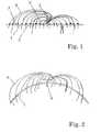
- a plasterboard 1has a visible side 2 and a rear side 3.
- a multiplicity of light-conducting fibers 4leads from the back through corresponding holes through the plate and ends on the visible side.
- the Fibersare combined into a bundle 5 with a Projector 6 optically coupled.
- the projectoris on the Back of plate 1 mounted.
- the fibersare in a pattern over the plate surface distributed, which corresponds to one or more constellations.
- the fiberscan be used individually or in groups of two, three or more fibers run through the plate. It depends on one or more fibers are passed through a hole, the respective point of light is smaller or larger.
- the boardcan also be made from one other material, such as Fermacell, Particle board etc.
- the fibers 4consist of glass or Plastic.
- a fiber bundle and a projectortheir two or more can also be arranged. With several Projectors can have different colors become.
- the projectorscan be used with a color wheel Change color be provided. If at one Fiber group the individual fibers with different colors Projectors are connected, there are mixed color effects.
- the productionis carried out as follows:
- the division of the plasterboardis marked and drilled from the visible side, the diameter of the Is adjusted depending on whether it is one, two or are several fibers that are pushed through. Then the hole is made with fine sandpaper sanded so that no drilling residues protrude.
- the fibersare now individually or in pairs or Triple groups etc. put through from behind and with one Acrylic cement glued so that the fibers in the Post-processing cannot slide away. Subsequently the panel is assembled with the fibers drawn in, glued, screwed or fastened by other methods.
- the advantages of the device described aboveare first of all that there are no outlet elements that can be seen when the light is switched off. This allows the installation of constellations in normal living areas with realistic elegance, or where a subtle effect is needed.
- the device according to the inventioncan be used wherever it is not possible to work with finished treated elements. When joining a ceiling cladding from prefabricated elements, one would always see the butt joints. Since the panel is only finally treated in the device according to the invention, any size, whether 1 m 2 with 50 light points or 1600 m 2 with 50,000 light points, can be realized without any disturbing butt joints being seen.
Landscapes
- Engineering & Computer Science (AREA)
- Physics & Mathematics (AREA)
- General Physics & Mathematics (AREA)
- Theoretical Computer Science (AREA)
- General Engineering & Computer Science (AREA)
- Astronomy & Astrophysics (AREA)
- Business, Economics & Management (AREA)
- Educational Administration (AREA)
- Educational Technology (AREA)
- Illuminated Signs And Luminous Advertising (AREA)
- Non-Portable Lighting Devices Or Systems Thereof (AREA)
Abstract
Description
Translated fromGermanDie Erfindung betrifft eine Einrichtung zur Erzeugung einesLichteffekts mit einer Vielzahl von Lichtpunkten,beispielsweise zur Simulation eines Sternenhimmels.The invention relates to a device for generating aLight effect with a variety of light points,for example to simulate a starry sky.
Lichteffekteinrichtungen, die beispielsweise einenSternenhimmel abbilden, sind bekannt. Sie bestehen auseiner Vielzahl von klein dimensionierten Lichtquellen, dieentsprechend einem gewünschten Muster über eine Fläche, inder Regel die Decke einer Raums, verteilt angeordnet sindund die entweder alle gemeinsam oder individuell ein- undausschaltbar oder intensitätsgeregelt sind.Light effect devices, for example aMapping the starry sky is well known. they consist ofa variety of small-sized light sources thataccording to a desired pattern over a surface, inusually the ceiling of a room, are arranged distributedand which either all together or individuallycan be switched off or intensity-controlled.
Die bekannten Einrichtungen dieser Art haben den Nachteil,dass die Lichtquellen im ausgeschalteten Zustand beiTageslicht oder Allgemeinbeleuchtung sichtbar sind. Diesist optisch störend und beeinträchtigt in einem gewissenMass den erwünschen Effekt der Einrichtung.The known devices of this type have the disadvantagethat the light sources when switched offDaylight or general lighting are visible. Thisis visually distracting and impaired to a certain extentMeasured the desired effect of the facility.
Der Erfindung liegt die Aufgabe zugrunde, eineLichteffekteinrichtung ohne die erwähnten Nachteilebereitzustellen.The invention has for its object aLight effects device without the disadvantages mentionedto provide.
Erfindungsgemäss wird dies erreicht durch eine Trägerplattemit einer Sichtseite und einer Rückseite, einen an derRückseite angeordneten Projektor und von der Sichtseitedurch die Platte zur Rückseite führende und mit demProjektor optisch gekoppelte, lichtleitende Fasern. DiePlatte kann dabei eben oder drei-dimensional geformt,beispielsweise gewölbt sein. Es können gleichzeitig mehrere Projektoren an der Rückseite angeordnet sein. DieProjektoren können mit einem Farbrad ausgerüstet sein.According to the invention, this is achieved by means of a carrier platewith a visible side and a back, one on theRear arranged projector and from the visible sidethrough the plate to the back and with theProjector optically coupled, light-guiding fibers. TheThe plate can be flat or three-dimensional,for example, be arched. Several can be used at the same timeProjectors can be arranged on the back. TheProjectors can be equipped with a color wheel.
Im folgenden werden anhand der beiliegenden Zeichnungenbevorzugte Ausführungsbeispiele der Erfindung beschrieben.Es zeigen
Eine Platte 1 aus Gipskarton besitzt eine Sichtseite 2 undeine Rückseite 3. Eine Vielzahl von lichtleitenden Fasern 4führt von der Rückseite durch entsprechende Bohrungen inder Platte hindurch und endet auf der Sichtseite. DieFasern sind zu einem Bündel 5 zusammengefasst mit einemProjektor 6 optisch gekoppelt. Der Projektor ist auf derRückseite der Platte 1 montiert.A
Die Fasern sind gemäss einem Muster über die Plattenflächeverteilt, das einem oder mehreren Sternbildern entspricht.Die Fasern können einzeln oder in Gruppen von zwei, dreioder mehr Fasern durch die Platte verlaufen. Je nachdem, obeine oder mehrere Fasern durch eine Bohrung geführt sind,ist der jeweilige Lichtpunkt kleiner oder grösser.The fibers are in a pattern over the plate surfacedistributed, which corresponds to one or more constellations.The fibers can be used individually or in groups of two, threeor more fibers run through the plate. It depends onone or more fibers are passed through a hole,the respective point of light is smaller or larger.
Anstelle von Gipskarton kann die Platte auch aus einemanderen Material bestehen, wie beispielsweise Fermacell,Spanplatte etc. Die Fasern 4 bestehen aus Glas oderKunststoff.Instead of plasterboard, the board can also be made from oneother material, such as Fermacell,Particle board etc. The
Anstelle eines Faserbündels und eines Projektors könnenauch deren zwei oder mehr angeordnet werden. Bei mehrerenProjektoren können unterschiedliche Farben vorgesehenwerden. Die Projektoren können mit einem Farbrad zumWechseln der Farbe versehen sein. Wenn bei einerFasergruppe die einzelnen Fasern mit verschiedenfarbigenProjektoren verbunden sind, ergeben sich Mischfarbeffekte.Instead of a fiber bundle and a projectortheir two or more can also be arranged. With severalProjectors can have different colorsbecome. The projectors can be used with a color wheelChange color be provided. If at oneFiber group the individual fibers with different colorsProjectors are connected, there are mixed color effects.
Die Herstellung wird wie folgt vorgenommen:The production is carried out as follows:
Zuerst wird eine Unterkonstruktion für die Gipskartondeckeerstellt. Danach werden die Sterne je nach Grösse desRaumes eingeteilt (kleiner Raum ca. 50 Lichtpunkte pro qm,grösserer Raum ca. 30 Lichtpunkte pro qm, die wiederum inEiner-, Zweier- oder Dreierelemente eingeteilt werden.First, a substructure for the plasterboard ceilingcreated. After that, the stars, depending on the size of theDivided into rooms (small room approx. 50 light points per sqm,larger room approx. 30 light points per square meter, which in turn inOne, two or three elements can be divided.
Nun wird die Aufteilung der Gipskartonplatte angezeichnetund von der Sichtseite gebohrt, wobei der Durchmesser desBohrers angepasst ist, je nachdem, ob es ein, zwei odermehrere Fasern sind, die durchgesteckt werden.Anschliessend wird das Loch mit einem feinen Schleifpapierverschliffen, damit keine Bohrrückstände vorstehen.Now the division of the plasterboard is markedand drilled from the visible side, the diameter of theIs adjusted depending on whether it is one, two orare several fibers that are pushed through.Then the hole is made with fine sandpapersanded so that no drilling residues protrude.
Die Fasern werden nun einzeln oder in Zweier- oderDreiergruppen etc. von hinten durchgesteckt und mit einemAcrylkitt verklebt, damit die Fasern bei derNachbearbeitung nicht wegrutschen können. Anschliessendwird die Platte mit den eingezogenen Fasern montiert,geklebt, verschraubt oder mit anderen Methoden befestigt.The fibers are now individually or in pairs orTriple groups etc. put through from behind and with oneAcrylic cement glued so that the fibers in thePost-processing cannot slide away. Subsequentlythe panel is assembled with the fibers drawn in,glued, screwed or fastened by other methods.
Danach werden die vorstehenden Fasern grob abgezwickt,jedoch noch immer etwas vorstehend. Sämtliche Fugen werdenverspachtelt und verschliffen zur Aufnahme von Farbe oderähnlichen Finishbehandlungen. Jetzt wird die gesamte Fläche mit einem Füller gespritzt, um noch restlichePorenöffnungen zu schliessen. Danach wird zweimal mit Farbegespritzt. Nach dem Trocknen wird der noch vorstehende Teilder Fasern bis auf einen Rest von 1 mm Länge abgezwickt.Der verbleibende vorstehende Teil ergibt einen funkelndenSterneffekt. Ausserdem könnte man die Fasern später, fallsz.B nach einer Farbbehandlung nötig, nachziehen.Then roughly pinch off the protruding fibers,however still slightly protruding. All joints will befilled and sanded to take up paint orsimilar finish treatments. Now the entire areasprayed with a filler to make any remainingTo close pore openings. After that, paint twicesprayed. After drying, the part still protrudingthe fibers are pinched off to a length of 1 mm.The remaining part above gives a sparkling oneStar effect. You could also use the fibers later, ife.g. necessary after a color treatment.
Die Vorteile der vorstehend beschriebenen Einrichtungbestehen zum einen vor allem darin, dass es keineAustrittselemente gibt, die man sieht, wenn das Lichtausgeschaltet ist. Dies ermöglicht den Einbau vonSternbildern auch in ganz normalen Wohnbereichen inrealistischer Eleganz, oder dort wo ein dezentes Effektbildbenötigt wird. Zum anderen kann die erfindungsgemässeEinrichtung überall dort eingesetzt werden, wo nicht mitfertig behandelten Elementen gearbeitet werden kann. BeiZusammenfügung einer Deckenverkleidung aus vrgefertigtenElementen würde man immer die Stossfugen sehen. Da bei derEinrichtung gemäss der Erfindung die Platte erstabschliessend behandelt wird, kann jede Grösse, ob 1 m2 mit50 Lichtpunkten oder 1600 m2 mit 50000 Lichtpunkten,realisiert werden, ohne dass man störende Stossfugen sieht.The advantages of the device described above are first of all that there are no outlet elements that can be seen when the light is switched off. This allows the installation of constellations in normal living areas with realistic elegance, or where a subtle effect is needed. On the other hand, the device according to the invention can be used wherever it is not possible to work with finished treated elements. When joining a ceiling cladding from prefabricated elements, one would always see the butt joints. Since the panel is only finally treated in the device according to the invention, any size, whether 1 m2 with 50 light points or 1600 m2 with 50,000 light points, can be realized without any disturbing butt joints being seen.
Bei der in Fig. 2 gezeigten Ausführungsform ist die Plattevon unten gesehen konkav gewölbt. Bei dieser Form ergibtsich ein noch realistischerer Effekt.In the embodiment shown in Fig. 2, the plate isseen concave from below. With this form it resultsan even more realistic effect.
Claims (4)
Translated fromGermanApplications Claiming Priority (2)
| Application Number | Priority Date | Filing Date | Title |
|---|---|---|---|
| CH208299 | 1999-11-16 | ||
| CH208299ACH693650A5 (en) | 1999-11-16 | 1999-11-16 | Light effect device. |
Publications (1)
| Publication Number | Publication Date |
|---|---|
| EP1102231A1true EP1102231A1 (en) | 2001-05-23 |
Family
ID=4225488
Family Applications (1)
| Application Number | Title | Priority Date | Filing Date |
|---|---|---|---|
| EP00811087AWithdrawnEP1102231A1 (en) | 1999-11-16 | 2000-11-16 | Lighting effect producing device |
Country Status (2)
| Country | Link |
|---|---|
| EP (1) | EP1102231A1 (en) |
| CH (1) | CH693650A5 (en) |
Cited By (7)
| Publication number | Priority date | Publication date | Assignee | Title |
|---|---|---|---|---|
| DE102004026835A1 (en)* | 2004-05-28 | 2005-12-22 | E.I.S. Electronics Gmbh | Composite component and method for its production |
| DE102005016116A1 (en)* | 2005-04-08 | 2006-10-19 | Brumberg Leuchten Gmbh & Co. Kg | Light for producing decorative light effects comprises a housing having openings for waveguides |
| WO2009000448A1 (en)* | 2007-06-25 | 2008-12-31 | Airbus Operations Gmbh | Interior trim panel with least one lighting element and method for producing an interior trim panel of this kind |
| WO2010015661A1 (en)* | 2008-08-06 | 2010-02-11 | Airbus Operations Gmbh | Area projection system for reproducing a visual signal on a surface |
| DE202013011362U1 (en) | 2013-12-19 | 2014-02-05 | iSYS RTS GmbH | Device for receiving a plurality of optical fibers |
| CN103713393A (en)* | 2013-12-17 | 2014-04-09 | 江苏东方创意文化产业有限公司 | Image display system and toy using image display system |
| EP4311979A1 (en) | 2022-07-27 | 2024-01-31 | Uno Minda Europe GmbH | Lighting module |
Citations (7)
| Publication number | Priority date | Publication date | Assignee | Title |
|---|---|---|---|---|
| US3470629A (en)* | 1967-09-01 | 1969-10-07 | Singer General Precision | Method of visually simulating star fields and the like |
| JPS5865469A (en)* | 1981-10-15 | 1983-04-19 | 吉仲 英樹 | Celestial sphere indicating apparatus |
| JPH01227180A (en)* | 1988-03-08 | 1989-09-11 | Dx Antenna Co Ltd | Heavenly body display device |
| JPH02259687A (en)* | 1989-03-31 | 1990-10-22 | Andoriyuusu Maachiyandaisu:Kk | Dome having optical device for embodying starry sky |
| JPH05133065A (en)* | 1991-11-15 | 1993-05-28 | Matsushita Electric Works Ltd | Building panel |
| GB2308896A (en)* | 1993-11-09 | 1997-07-09 | Sanyo Electric Co | Sign illumination |
| WO1998010316A1 (en)* | 1996-09-05 | 1998-03-12 | Inwave Corporation | Adjustable terminal housing for optical fiber |
- 1999
- 1999-11-16CHCH208299Apatent/CH693650A5/ennot_activeIP Right Cessation
- 2000
- 2000-11-16EPEP00811087Apatent/EP1102231A1/ennot_activeWithdrawn
Patent Citations (7)
| Publication number | Priority date | Publication date | Assignee | Title |
|---|---|---|---|---|
| US3470629A (en)* | 1967-09-01 | 1969-10-07 | Singer General Precision | Method of visually simulating star fields and the like |
| JPS5865469A (en)* | 1981-10-15 | 1983-04-19 | 吉仲 英樹 | Celestial sphere indicating apparatus |
| JPH01227180A (en)* | 1988-03-08 | 1989-09-11 | Dx Antenna Co Ltd | Heavenly body display device |
| JPH02259687A (en)* | 1989-03-31 | 1990-10-22 | Andoriyuusu Maachiyandaisu:Kk | Dome having optical device for embodying starry sky |
| JPH05133065A (en)* | 1991-11-15 | 1993-05-28 | Matsushita Electric Works Ltd | Building panel |
| GB2308896A (en)* | 1993-11-09 | 1997-07-09 | Sanyo Electric Co | Sign illumination |
| WO1998010316A1 (en)* | 1996-09-05 | 1998-03-12 | Inwave Corporation | Adjustable terminal housing for optical fiber |
Non-Patent Citations (3)
| Title |
|---|
| PATENT ABSTRACTS OF JAPAN vol. 013, no. 547 (P - 971) 7 December 1989 (1989-12-07)* |
| PATENT ABSTRACTS OF JAPAN vol. 015, no. 016 (P - 1152) 14 January 1991 (1991-01-14)* |
| PATENT ABSTRACTS OF JAPAN vol. 017, no. 510 (M - 1480) 14 September 1993 (1993-09-14)* |
Cited By (13)
| Publication number | Priority date | Publication date | Assignee | Title |
|---|---|---|---|---|
| US7121702B2 (en) | 2004-05-28 | 2006-10-17 | E.I.S. Electronics Gmbh | Laminate material component and method for its production |
| DE102004026835B4 (en)* | 2004-05-28 | 2015-08-27 | E.I.S. Electronics Gmbh | Composite component and method for its production |
| DE102004026835A1 (en)* | 2004-05-28 | 2005-12-22 | E.I.S. Electronics Gmbh | Composite component and method for its production |
| DE102005016116B4 (en)* | 2005-04-08 | 2012-06-06 | Brumberg Leuchten Gmbh & Co. | Luminaire with a plurality of optical fiber means and at least one high-power light emitting diode |
| DE102005016116A1 (en)* | 2005-04-08 | 2006-10-19 | Brumberg Leuchten Gmbh & Co. Kg | Light for producing decorative light effects comprises a housing having openings for waveguides |
| US8398281B2 (en) | 2007-06-25 | 2013-03-19 | Airbus Operations Gmbh | Interior trim panel with at least one lighting element and method for producing an interior trim panel of this kind |
| WO2009000448A1 (en)* | 2007-06-25 | 2008-12-31 | Airbus Operations Gmbh | Interior trim panel with least one lighting element and method for producing an interior trim panel of this kind |
| WO2010015661A1 (en)* | 2008-08-06 | 2010-02-11 | Airbus Operations Gmbh | Area projection system for reproducing a visual signal on a surface |
| US8616704B2 (en) | 2008-08-06 | 2013-12-31 | Airbus Operations Gmbh | Area projection system for reproducing a visual signal on a surface |
| CN103713393A (en)* | 2013-12-17 | 2014-04-09 | 江苏东方创意文化产业有限公司 | Image display system and toy using image display system |
| DE202013011362U1 (en) | 2013-12-19 | 2014-02-05 | iSYS RTS GmbH | Device for receiving a plurality of optical fibers |
| EP4311979A1 (en) | 2022-07-27 | 2024-01-31 | Uno Minda Europe GmbH | Lighting module |
| DE102022207724A1 (en) | 2022-07-27 | 2024-02-01 | UNO MINDA Europe GmbH | LIGHTING MODULE |
Also Published As
| Publication number | Publication date |
|---|---|
| CH693650A5 (en) | 2003-11-28 |
Similar Documents
| Publication | Publication Date | Title |
|---|---|---|
| EP1268953B1 (en) | Floor or wall covering from ceramics, wood, plastic, natural or artificial stone, and a tile or panels used for the same | |
| EP0846915B1 (en) | Inner room light | |
| DE10206613A1 (en) | Illumination device with light conductors has light conductors with output coupling arrangements and/or reflectors so light can be coupled out at least through part of side surfaces | |
| DE102004010920A1 (en) | Decorative component for e.g. decorating interior or exterior of building, includes translucent carrier and thin opaque layer which enables passage of small amount of light | |
| EP1102231A1 (en) | Lighting effect producing device | |
| EP1114276B1 (en) | Lamp with colour effect | |
| CH674093A5 (en) | ||
| EP1176362A1 (en) | Flat light-emitting elements system | |
| DE102009060565A1 (en) | lamp | |
| DE102017203829A1 (en) | Decoration object with a globe | |
| DE102020131013A1 (en) | Display device for a vehicle component | |
| DE4332458C1 (en) | Decorative panel | |
| DE102005017639A1 (en) | Fiber optics arrangement for optical data communication, has crystal clear connecting material with light controlling/reflecting particles such as glass hollow balls having thin layer and arranged between light conducting units | |
| DE102019000068A1 (en) | jigsaw puzzle | |
| DE202012008800U1 (en) | lamp | |
| EP1106915B1 (en) | Flat luminous elements system | |
| DE202013011362U1 (en) | Device for receiving a plurality of optical fibers | |
| EP1106914A1 (en) | Flat light-emitting elements system | |
| DE20021153U1 (en) | Glass fiber decoration item | |
| DE9110573U1 (en) | lamp | |
| DE10214761B4 (en) | Cladding element for buildings, in particular ceilings | |
| DE102022000580B3 (en) | Illuminated floor with a channel system for inserting LED ribbon cables and method for its manufacture | |
| DE102012105621A1 (en) | Lighting device for illumination of rooms of building, comprises light source and deflection arrangement, which is adapted to redirect radiation emitted from light source for illuminating room, and has two or multiple deflecting mirrors | |
| DE19705845A1 (en) | Lamp system | |
| DE19756133C2 (en) | Transparent plate-shaped information carrier |
Legal Events
| Date | Code | Title | Description |
|---|---|---|---|
| PUAI | Public reference made under article 153(3) epc to a published international application that has entered the european phase | Free format text:ORIGINAL CODE: 0009012 | |
| AK | Designated contracting states | Kind code of ref document:A1 Designated state(s):AT BE CH CY DE DK ES FI FR GB GR IE IT LI LU MC NL PT SE TR | |
| AX | Request for extension of the european patent | Free format text:AL;LT;LV;MK;RO;SI | |
| 17P | Request for examination filed | Effective date:20011123 | |
| AKX | Designation fees paid | Free format text:AT BE CH CY DE DK ES FI FR GB GR IE IT LI LU MC NL PT SE TR | |
| STAA | Information on the status of an ep patent application or granted ep patent | Free format text:STATUS: THE APPLICATION HAS BEEN WITHDRAWN | |
| 18W | Application withdrawn | Withdrawal date:20020516 |