EP1099321B1 - Optical communication systems, apparatuses, and methods - Google Patents
Optical communication systems, apparatuses, and methodsDownload PDFInfo
- Publication number
- EP1099321B1 EP1099321B1EP99937360AEP99937360AEP1099321B1EP 1099321 B1EP1099321 B1EP 1099321B1EP 99937360 AEP99937360 AEP 99937360AEP 99937360 AEP99937360 AEP 99937360AEP 1099321 B1EP1099321 B1EP 1099321B1
- Authority
- EP
- European Patent Office
- Prior art keywords
- optical
- waveband
- signal
- information carrying
- fiber
- Prior art date
- Legal status (The legal status is an assumption and is not a legal conclusion. Google has not performed a legal analysis and makes no representation as to the accuracy of the status listed.)
- Expired - Lifetime
Links
- 230000003287optical effectEffects0.000titleclaimsdescription245
- 238000000034methodMethods0.000titleclaimsdescription18
- 238000004891communicationMethods0.000titleclaimsdescription17
- 230000005540biological transmissionEffects0.000claimsdescription78
- 239000000835fiberSubstances0.000claimsdescription53
- 238000012545processingMethods0.000claimsdescription45
- 229910052691ErbiumInorganic materials0.000claimsdescription12
- UYAHIZSMUZPPFV-UHFFFAOYSA-NerbiumChemical compound[Er]UYAHIZSMUZPPFV-UHFFFAOYSA-N0.000claimsdescription11
- 239000013307optical fiberSubstances0.000claimsdescription10
- 239000004973liquid crystal related substanceSubstances0.000claimsdescription2
- 239000004065semiconductorSubstances0.000claimsdescription2
- 230000015572biosynthetic processEffects0.000claims1
- 230000001052transient effectEffects0.000description14
- 239000006185dispersionSubstances0.000description7
- 238000001514detection methodMethods0.000description6
- 230000002238attenuated effectEffects0.000description4
- 238000006243chemical reactionMethods0.000description4
- 238000011161developmentMethods0.000description4
- 239000002019doping agentSubstances0.000description4
- 230000008569processEffects0.000description4
- 230000006378damageEffects0.000description3
- 238000009826distributionMethods0.000description3
- 238000005516engineering processMethods0.000description3
- 238000012986modificationMethods0.000description3
- 230000004048modificationEffects0.000description3
- 238000012546transferMethods0.000description3
- -1Erbium ionsChemical class0.000description2
- 230000001427coherent effectEffects0.000description2
- 230000007423decreaseEffects0.000description2
- 230000008030eliminationEffects0.000description2
- 238000003379elimination reactionMethods0.000description2
- 230000006870functionEffects0.000description2
- YBMRDBCBODYGJE-UHFFFAOYSA-Ngermanium dioxideChemical compoundO=[Ge]=OYBMRDBCBODYGJE-UHFFFAOYSA-N0.000description2
- 230000003993interactionEffects0.000description2
- 239000000463materialSubstances0.000description2
- 229910052761rare earth metalInorganic materials0.000description2
- 230000004044responseEffects0.000description2
- 230000008054signal transmissionEffects0.000description2
- 238000001228spectrumMethods0.000description2
- 230000003068static effectEffects0.000description2
- 238000002834transmittanceMethods0.000description2
- 229910052777PraseodymiumInorganic materials0.000description1
- 229910052769YtterbiumInorganic materials0.000description1
- 238000010521absorption reactionMethods0.000description1
- 230000003321amplificationEffects0.000description1
- 230000008901benefitEffects0.000description1
- 230000000903blocking effectEffects0.000description1
- 230000015556catabolic processEffects0.000description1
- 230000008859changeEffects0.000description1
- 238000007796conventional methodMethods0.000description1
- 230000008878couplingEffects0.000description1
- 238000010168coupling processMethods0.000description1
- 238000005859coupling reactionMethods0.000description1
- 230000003247decreasing effectEffects0.000description1
- 238000006731degradation reactionMethods0.000description1
- 230000002939deleterious effectEffects0.000description1
- 238000013461designMethods0.000description1
- 230000000694effectsEffects0.000description1
- 238000002839fiber optic waveguideMethods0.000description1
- RGNPBRKPHBKNKX-UHFFFAOYSA-NhexaflumuronChemical compoundC1=C(Cl)C(OC(F)(F)C(F)F)=C(Cl)C=C1NC(=O)NC(=O)C1=C(F)C=CC=C1FRGNPBRKPHBKNKX-UHFFFAOYSA-N0.000description1
- 230000036039immunityEffects0.000description1
- 230000006698inductionEffects0.000description1
- 230000010365information processingEffects0.000description1
- 230000007246mechanismEffects0.000description1
- 238000003199nucleic acid amplification methodMethods0.000description1
- 238000003909pattern recognitionMethods0.000description1
- 230000001902propagating effectEffects0.000description1
- 230000009467reductionEffects0.000description1
- 238000002310reflectometryMethods0.000description1
- 238000000926separation methodMethods0.000description1
- 238000009966trimmingMethods0.000description1
Images


Classifications
- H—ELECTRICITY
- H04—ELECTRIC COMMUNICATION TECHNIQUE
- H04J—MULTIPLEX COMMUNICATION
- H04J14/00—Optical multiplex systems
- H04J14/02—Wavelength-division multiplex systems
- H04J14/0201—Add-and-drop multiplexing
- H04J14/0202—Arrangements therefor
- H04J14/0213—Groups of channels or wave bands arrangements
- H—ELECTRICITY
- H04—ELECTRIC COMMUNICATION TECHNIQUE
- H04Q—SELECTING
- H04Q11/00—Selecting arrangements for multiplex systems
- H04Q11/0001—Selecting arrangements for multiplex systems using optical switching
- H04Q11/0005—Switch and router aspects
- H—ELECTRICITY
- H04—ELECTRIC COMMUNICATION TECHNIQUE
- H04Q—SELECTING
- H04Q11/00—Selecting arrangements for multiplex systems
- H04Q11/0001—Selecting arrangements for multiplex systems using optical switching
- H04Q11/0005—Switch and router aspects
- H04Q2011/0007—Construction
- H04Q2011/0015—Construction using splitting combining
- H—ELECTRICITY
- H04—ELECTRIC COMMUNICATION TECHNIQUE
- H04Q—SELECTING
- H04Q11/00—Selecting arrangements for multiplex systems
- H04Q11/0001—Selecting arrangements for multiplex systems using optical switching
- H04Q11/0005—Switch and router aspects
- H04Q2011/0007—Construction
- H04Q2011/0016—Construction using wavelength multiplexing or demultiplexing
- H—ELECTRICITY
- H04—ELECTRIC COMMUNICATION TECHNIQUE
- H04Q—SELECTING
- H04Q11/00—Selecting arrangements for multiplex systems
- H04Q11/0001—Selecting arrangements for multiplex systems using optical switching
- H04Q11/0005—Switch and router aspects
- H04Q2011/0007—Construction
- H04Q2011/0022—Construction using fibre gratings
- H—ELECTRICITY
- H04—ELECTRIC COMMUNICATION TECHNIQUE
- H04Q—SELECTING
- H04Q11/00—Selecting arrangements for multiplex systems
- H04Q11/0001—Selecting arrangements for multiplex systems using optical switching
- H04Q11/0005—Switch and router aspects
- H04Q2011/0007—Construction
- H04Q2011/0035—Construction using miscellaneous components, e.g. circulator, polarisation, acousto/thermo optical
- H—ELECTRICITY
- H04—ELECTRIC COMMUNICATION TECHNIQUE
- H04Q—SELECTING
- H04Q11/00—Selecting arrangements for multiplex systems
- H04Q11/0001—Selecting arrangements for multiplex systems using optical switching
- H04Q11/0062—Network aspects
- H04Q2011/0075—Wavelength grouping or hierarchical aspects
Definitions
- the present inventionis directed generally to network, transmission and communication systems. More particularly, the invention relates to optical information network, transmission and communication systems and optical components, such as cross connect switches, add/drop devices, demultiplexers, and multiplexers, for use therein.
- Optical transmission systemsprovide substantially larger information transmission bandwidths than electrical systems, which provides for increased information transmission capacities.
- SDMspace division multiplex
- Optical TDM systemsare generally analogous to electrical TDM systems in that the signals are transmitted on a common line, but spaced in time. The transmission of the signals is in a known sequence allows the plurality of distinct signals to be separated after transmission.
- a problem with TDM transmissionis the transmission bandwidth in the waveguide increases with each additional multiplexed signal.
- informationcan be transmitted through a waveguide via a first series of optical signals separated in time by an interval ⁇ t. Additional information can also be transmitted over the same waveguide using a second series of optical signals during the time interval ⁇ t by merely offsetting the transmission of the first and second series of signals in time. While an optical signal in each series is only transmitted through the waveguide every ⁇ t interval, two signals, or n signals in the general case, are passing through the waveguide during each interval. Therefore, the overall transmission rate in TDM systems increases directly with the number of signals transmitted.
- Signal transmission rates in fiber optic waveguidesare generally limited by the interactions between the optical signal (i.e., light pulse) and microstructural features of the waveguide material. As the transmission rate is increased, signal dispersion in the fiber and other transmission effects deleterious to signal quality begin to occur as a result of the interactions.
- Optical signalsare typically transmitted in wavelengths that minimize dispersion in the fiber.
- older optical systemsare commonly operated around 1310 nm and employ SMF-28 fiber manufactured by Corning, or its equivalent, which has minimum dispersion at or near 1310 nm.
- Another type of fiberknown as dispersion shifted fiber, has its minimum dispersion at or near 1550 nm.
- a third type of fiber sold by Corning as LS fiber and by Lucent Technology as TrueWavehas its minimum dispersion at or near 1550 nm.
- each fiberhas varying immunity to other signal degradation mechanisms, such as four wave mixing, at increased transmission rates.
- TDM systemswhich increase capacity by increasing transmission rates, generally have only a limited potential for further increasing the capacity of optical transmission systems.
- WDMwavelength division multiplex
- the waveguide materialdoes not realistically limit the information bandwidth that can be placed on a single optical fiber in a WDM system.
- One skilled in the artcan also appreciate that the number of wavelengths that can be used to transmit information over a single waveguide is currently limited by the complexity of the transmission and receiving equipment required to generate, transmit, receive, and separate the multiple wavelength signal.
- optical transmission systemsmust convert the optical signal to an electrical signal during transmission to perform transmission functions, such as signal amplification and switching.
- the optical to electrical conversion, and vice versasubstantially limits the overall transmission speed of the network, and increases transmission losses in the network.
- optical fiber amplifiersproduced by doping the optical fiber with Erbium ions (Er 3+ ) or other elements has allowed for the elimination of electrical amplifiers and the requisite time delay and costs associated with signal conversion.
- optical fiber amplifiershave proven effective for amplifying a plurality of wavelengths without a commensurate increase in the complexity of the amplifier as additional wavelengths are included in the WDM signal.
- optical cross-connect switchesgreatly increase in complexity as the number of waveguides entering and exiting the switch and the number of wavelengths per waveguide increases. As a result, the expansion of all optical systems has been somewhat inhibited by the lack of simple, efficient, and economically attractive optical cross-connect switching systems.
- a number of optical cross-connect switchesare based on one or more 1x2 signal splitters or 2x2 signal couplers used in conjunction with one or more wavelength filters, such as described in U.S. Patent No. 5,446,809 issued to Fritz et al.
- the complexity of these types of switchincreases not only with the number of inputs and outputs in the switch, but also with the number of wavelengths being switched. For example, if a 2x2 switch is provided to switch two eight wavelength WDM input signals to two output signals, the switch would have to include 32 gratings to allow all wavelengths to be switched. However, if a 4x4 switch is provided to switch four sixteen wavelength WDM input signals to four output signals, 256 gratings will be required. In addition, the flexibility of the switch is limited because additional gratings or filters must be added to each waveguide connecting each input to each output of the switch for every wavelength that is to be switched.
- Switchescan be provided that "block” the switching of certain wavelengths to prevent destruction of two signals on a common wavelength. Switches can also be provided with wavelength converters that are used to change the wavelength of a signal, in lieu of blocking the signal, to prevent the destruction of the signal.
- U.S. Patent No. 5,627,925 issued to Alferness et al.discloses an example of a switch that includes wavelength converters to provide a nonblocking switch. As expected, the use of wavelength converters adds a further degree of complexity to the design and function of optical cross-connect switches.
- U.S. Patent No. 4,821,255 issued to Kobrinskidiscloses an optical system employing transmission systems that transmit data at a different wavelength to each destination receiving system, i.e., N wavelengths for N receiving systems. In this manner, the optical system does not require a nonblocking switch and the assignment of a specific wavelength to each receiving system allows for a passive optical connection ("hard wire") between a transmission demultiplexer and a receiving multiplexer.
- the same N wavelengthscan be transmitted by each transmitting system if the receiving system is coordinated to receive a different wavelength from each transmitting system.
- Wavelength coordinationeliminates the need for wavelength converters and allows the same transmitters and receivers to be used in the system.
- a difficulty with passive switching systemsis that the streamlined nature renders the switch somewhat inflexible. For example, a specified wavelength is used to transmit signals between a transmission system and a receiving system. Therefore, it may be difficult to transmit multiple signals from one transmitting system to one receiving system at any one time. It is presumably possible to assign additional wavelengths to each of N transmitter/receiver combinations; however, for each wavelength added to each system, either N 2 hard wire connections must be made.
- optical componentssuch as add/drop devices, demultiplexers and multiplexers, used in optical processing nodes between the transmitter and receivers increase in complexity and cost as additional channels are added to the system. In addition, these components most likely have to be replaced when a system is reconfigured or additional channels are to be added to the system.
- optical systems and optical componentsthat allow for increased network capacity and flexibility.
- One aspect of whichis to reduce the complexity of the equipment and increase the efficiency of the transmission system.
- US 5,191,626discloses an optical transmission system comprising an optical transmitter configured to transmit information via information carrying wavelengths, an optical receiver configured to receive the information transmitted via the information carrying wavelengths, and one optical processing node.
- This systemalso comprises controllable linear power dividers.
- this systemdoes not overcome technical problems encountered when a high capacity processing of the information without increasing complexity is wanted.
- This present inventionproposes an optical transmission system according to claim 1, a method of passing information to a destination according to claim 21, and an optical switch according to claim 25.
- An optical transmission system of the present inventionincludes one or more optical signal transmitters and optical signal receivers optically communicating via one or more intermediate optical processing nodes.
- Each optical transmitterincludes one or more optical sources, such as modulated lasers, and is configured to transmit information via one or more information carrying wavelengths.
- Each optical receiveris configured to receive one or more of the information carrying wavelengths using one or more various detection techniques, such as direct detection using optical wavelength filters and photodiodes, or indirect detection using coherent detectors.
- the intermediate optical processing nodesinclude optical switches, add and/or drop devices including at least one waveband selector configured to pass and substantially prevent the passage of optical wavebands that include a plurality of information carrying wavelengths from the transmitter to the receiver.
- the optical processing nodesprovide for information management and processing in wavebands, instead of separating individual information carrying wavelengths from the signal and individually processing each wavelength. In this manner, high capacity processing of the information can be achieved without the prior complexities involved with increasing capacity.
- the processing of pluralities of individual wavelengthsfurther provides for accommodating varying numbers and distributions of individual information carrying wavelengths in the system without having to reconfigure or replace system components.
- the optical processing nodeincludes a switch providing cross connections between a plurality of transmitters and receivers.
- Optical signals including one or more information carrying wavelengthsare transmitted to optical switch input ports and are distributed to optical switch output ports by splitting and/or waveband demultiplexing the optical signals depending upon the type of waveband selector used in the switch.
- Waveband selectorsinclude at least one switch, gate, or filter, such as an erbium or mechanical switch, a Bragg grating, or a Mach-Zehnder or Fabry-Perot filter.
- the waveband selectorsare generally configured to pass one or more optical wavebands from the input port to the output port in one mode and/or to substantially prevent the passage the optical wavebands in another mode.
- a signalis generally considered to be substantially prevented from passage, if the signal is sufficiently attenuated such that a remnant of the attenuated signal passing through the waveband selector does not destroy signals that have been selectively passed through the optical processing node. For example, a 40 dB attenuation of a signal will generally be sufficient to prevent cross-talk interference between remnant signals and signals passing through the optical processing node.
- each input signalis waveband demultiplexed to separate the input signal into waveband signals.
- Each waveband signalis then split and each split waveband signal passed through a switch to a respective output port.
- an erbium doped fiberis used as the switch in the waveband selector to pass, as well as to controllably amplify or attenuate, the split waveband signal to the output port when supplied with optical pump power. In the absence of pump power, the erbium fiber absorbs the waveband signal, which substantially prevents the passage of the signal.
- One or more optical combinersare provided at the output ports to combine split waveband signal from the waveband selector passing optical wavebands from the input ports.
- the optical signal at each input portcan also be demultiplexed according to a known destination of each waveband signal and the waveband signal is passed to the output port corresponding to the destination.
- the optical signalscan be transmitted to the switch in wavelengths that are unique to the signal destination to avoid the use of wavelength converters in the optical system.
- Bragg gratingseither reflective or transmissive, can be included in the waveband selector to switch any number of wavebands.
- the Bragg gratings of the present inventioninclude one grating produced to reflect an entire waveband or a series of gratings operated in concert that piecewise correspond to the waveband.
- tunable permanent Bragg gratingscan be provided corresponding to each of the wavebands to allow for dynamic reconfiguration of the switch.
- the optical processing nodecan include transient gratings to provide for additional reconfiguration of the processing node.
- Transient gratingcan be formed in the waveguide either by induction using a coupled circuit or via a writing circuit integrated with the transmission fiber.
- pluralities of nodesare interconnected to form a network.
- the nodesmay contain optical transmitters, receivers, add and/or drop devices/ports, and/or switching equipment depending upon whether the node is an origination and/or a destination node, and whether it is a terminal or an intermediate node.
- the network management systemis provisioned to assign wavelengths to information that can be transmitted to destination nodes in a manner to obviate the need for wavelength conversion at the optical switch. Wavelength assignment can be static or dynamically performed via a network management system, for example, at the client system interface with the optical network.
- the optical switches cross connecting the nodes and add and/or drop portsare configured to respectively switch and add/drop the information carrying wavelengths in wavebands without separately switching the individual wavelengths.
- the present inventionaddresses the aforementioned problems and provides apparatuses and methods to increase the efficiency and capacity of optical communication systems.
- optical systems 10 of the present inventionwill be described generally with reference to the drawings for the purpose of illustrating embodiments only and not for purposes of limiting the same.
- the optical system 10includes at least one optical transmitter 12 and at least one optical receiver 14, as shown in Fig. 1 .
- Each transmitter 12is configured to transmit information via one or more information carrying wavelengths 18 i,k contained in at least one waveband 16 1,i to the receivers 14.
- Each receiver 14is configured to receive the information carried via one or more of the information carrying wavelengths 18 i,k .
- the term "information"should be broadly construed to include any type of data, instructions, or signals that can be optically transmitted.
- the system 10further includes at least one intermediate optical processing node 20, such as an optical switch 22.
- the transmitter 12is configured to transmit an optical signal 24 containing one or more information carrying wavelengths 18 j along signal transmission waveguide, i.e., fiber, 26 to the switch 22 via input port 28.
- the optical processing node 20includes one or more waveband selectors, or selective element, 30 that are configured to pass and/or substantially prevent the passage of information in wavebands 16 i to the receiver 14 via output ports 32. Because the information is being manipulated in wavebands, the individual information carrying wavelengths 18 j within the waveband 16 i do not have to be separated in individual wavelengths to be managed and processed.
- the individual wavelengths 18 j within the waveband 16 ibe varied in the system 10 without affecting the configuration of the optical processing node 20. Wavelengths 18 j in the original signal 24 but not within the waveband 16 i are prevented from passing through to the receivers 14.
- optical signals 24can be produced including a number of wavebands 16, each of which may contain one or more information carrying wavelengths in a continuous band of wavelengths or a plurality of wavelength bands.
- a waveband 16can be defined as having a continuous range of -200 GHz containing 20 different information carrying wavelengths 18 1-20 spaced apart on a 10 GHz grid.
- the bandwidth of each wavebandcan be uniformly or variably sized depending upon the network capacity requirements.
- the bandwidth of the wavebandis not restricted, but can be varied to accommodate varying numbers of wavelengths.
- systems 10 of the present inventionare configured so that the optical processing nodes do not separate and process individual information carrying wavelengths during transmission from the transmitter to the receiver.
- optical processing nodes 20are configured to process the information in wavebands that may include any number of individual information carrying wavelengths.
- the processing of information in wavebandsdecreases the complexity involved in processing large numbers of channels, while increasing the flexibility of optical components deployed in the transmission path between transmitters and receivers.
- the bandwidth and number of information carrying wavelengths within a waveband in a networkcan be statically or dynamically allocated depending upon the information traffic flow in a given network segment.
- Fig. 2shows a more general arrangement of the system 10, which includes a plurality of transmitter 12 n optically connected via the switch 22 to a plurality of receiver 14 m .
- each transmitter 12 ntransmits an optical signal 24 n which includes one or more wavelengths 18 n,j through a waveguide 26 n to an input port 28 n of the switch 22.
- each transmittermay include one or more sources to transmit and one or more wavelength signals.
- each receivermay include one or more detectors for receiving the signals.
- An optical distributor 34 nsuch as a demultiplexer 36 and/or a splitter 38, is provided in the input port 28 n to distribute the signal 24 n to the waveband selectors 30 n,m .
- An optical combiner 40 msuch as a wavelength division multiplexer 42 or a coupler 44, is generally included to combine the wavelengths 18 m,k in waveband 16 m,i emerging from the waveband selectors 30 n,m and provide a modified signal 24' m .
- the modified signal 24' mexits the switch through the output port 32 m and passes along waveguide 26 to the receiver 14 m .
- Fig. 2shows only a waveband selector 30 connecting input port 28 1 to output port 32 1 .
- the switch 22will generally include at least one waveband selector 30 between each input port 28 and each output port 32.
- corresponding input and output portse.g. 28 1 and 32 1
- reference numeral subscriptsare generally not used in the remainder of the description to simplify the nomenclature.
- Transmitters 12 used in the system 10can include one or more optical emitters and sources that provide continuous wave and/or pulsed beams, such as one or more modulated lasers as is known in the art.
- the transmitter 12may also include narrow band incoherent sources such as described in U.S. Patent Nos. 5,191,586 and 5,268,910 issued to Huber or other optical sources for producing optical signals.
- Informationcan be directly or indirectly, e.g., externally, modulated, or alternatively upconverted, onto an optical wavelength, and the information itself may be a time division multiplexed signal.
- the transmitter 12can also be used to provide multiple information carrying wavelengths using techniques such as described in U.S. Patent No. 5,400,166 .
- Multiple information carrying wavelengthscan be placed on a single carrier from the transmitter 12 using techniques, such as subcarrier modulation (SCM).
- SCM techniquesare described in U.S. Patent Nos. 5,101,450 , 5,134,509 ,and 5,301,058 issued to Olshansky , 4,989,200 issued to Olshansky et al. , 5,432,632 issued to Watanabe and 5,596,436 issued to Sargis et al.
- the transmitters 12may be coupled to an external electrical network or part of an optical-electrical-optical (O/E/O) signal regenerator within an optical network.
- O/E/Ooptical-electrical-optical
- One skilled in the artwill appreciate that the selection of the transmitter 12 and the number of information carrying wavelengths will depend upon the desired information transfer rates for a particular transmitter/receiver system at the respective nodes. While the present invention provides the ability to substantially upgrade the transfer rate for the node, it does not require that older, slower nodes be upgraded upon implementation of the present invention.
- the receiver 14 and transmission fiber 26does not have to be upgraded to be compatible with the present invention.
- the capabilities of the receiving systemcan be taken in account when establishing wavebands to be transmitted to a particular receiver 14.
- the receiver 14will generally be used to separate the individual information carrying wavelengths 18 i,k in each waveband 16 i contained in the modified signal 24' and convert the information to one or more electrical signals.
- the receivermay include a number of a wavelength filters, such as Bragg gratings or demultiplexers, in combination with an optical to electrical converter (O/E), such as a photodiode, to provide for direct detection of the individual wavelengths.
- O/Eoptical to electrical converter
- the receiver 14may also provide for indirect detection of the individual wavelengths, such as by using coherent detector arrangements.
- the system 10may include other types of intermediate processing nodes 20, such as add and/or drop devices.
- the other intermediate processing nodescan be employed to selectively modify the wavebands in the signal 24' and pass a further modified signal 24" to successive switches 22 and to the receivers 14.
- the subsequent switches 22 between other intermediate processing nodes 20 and the receivers 14can be used to further process the signal 24" to produce a further modified signal 24"' which may include waveband subset 16 i1 .
- optical add and/or drop devices/portscan be embodied as a 2x2 switch that can provide for 100% programmable add/drop capability or by employing directional devices, such as couplers and/or circulators, with or without waveband selectors 30 to provide varying degrees of programmability, as will be further discussed.
- the receiver 14can also be used to further distribute the signal 24"' as a part of an O/E/O signal regenerator.
- an O/E/O regeneratorthe optical wavelengths received by the receiver 14 do not necessarily have to correspond to the optical wavelengths at which the information is further transmitted.
- Waveband selectors 30generally include at least one filter, gate, and/or switch configured to pass and/or substantially prevent the passage of at least one waveband 16 received from the inlet port 28 to the outlet port 32.
- a signalis generally considered to be substantially prevented from passage, if the signal is sufficiently attenuated such that a remnant of the attenuated signal that passes through the waveband selector does not destroy signals that have been selectively passed through the optical processing node 20.
- a 40 dB attenuation of a signalwill generally be sufficient to prevent cross-talk interference between remnant signals and signals being selectively passed through the optical processing node 20.
- the switch 22includes a waveband demultiplexer 36 and an optical signal splitter 38 coupled via a doped optical fiber 46 to the multiplexer 42 at the output port 32.
- the doped fiberis supplied with energy from the switch pump 48 to overcome the absorption of the doped fiber 46.
- the amount of energy supplied by the pump 48can be controlled to selectively amplify or attenuate a signal being passed through the waveband selector 30.
- the doped fiber 46will absorb the optical signal, thereby substantially preventing the passage of that portion of the signal to the outlet port 32.
- the wavebandscan be switched to any number of output ports including one to one switching and one to many broadcasting.
- the dopant in the doped optical fiber 46can be erbium or any other dopant including other rare earth elements that can render the fiber transmissive in one state and substantially less transmissive in another state.
- the selection of a dopant in the doped fiberwill depend upon the information carrying wavelengths that are to be switched in the system. Also, mechanical, electro-optic, liquid crystal, semiconductor, and other types of switches along with gratings, filters and gates, can be substituted for or used in combination with doped fiber 46 to achieve desired characteristics in the switch 22.
- the waveband selector 30may include reflective ( ⁇ 50% reflectance) and/or transmissive ( ⁇ 50% reflectance) selective elements that can be used to pass, either reflect or transmit, any of the wavebands 16 that comprise the signal 24.
- the waveband selector 30may employ Mach-Zehnder filters, Fabry-Perot filters, and Bragg gratings to perform the waveband selection.
- waveband selectors 130 and 230can include a plurality of in-fiber reflective Bragg gratings 50 ( Fig. 5 ) and/or transmissive Bragg gratings 52 ( Fig. 6 ) to pass selected wavebands to the output ports 32.
- Each grating, 50 and 52can be provided to pass selected wavebands to output ports 32.
- the waveband selector 30may include a series of multiple Bragg gratings that provide for piecewise coverage of the waveband.
- the multiple grating selectorcan be tuned to individual idler gaps or telescoped to one or more common idler gaps to decrease the idler gap bandwidth.
- the number of gratings in Figs. 6 and 7is shown as being equal to the number of wavebands 16 being switched. However, the number of selectors provided in the switch does not necessarily have to correspond to number of wavebands 16 currently in the system.
- the configurations shown in Figs. 5-11may also be suitable for use in add/drop multiplexers, as well as demultiplexers or multiplexers, in which any number of wavebands can be processed.
- the waveband selectors 30can also be used to pass multiple wavebands to reduce the number of components in the system 10.
- the wavebands 16can be selected to overlap to allow one or more wavelengths 18 to be transmitted in multiple wavebands 16.
- a waveband selector 130can include a three port circulator 54 used in conjunction with the plurality of reflective Bragg gratings 50 using a configuration similar those discussed in U.S. Patent Nos. 5,283,686 and 5,579,143 issued to Huber , and 5,608,825 issued to Ip .
- a waveband selector 230employs transmissive gratings 52 to transmit selected wavebands to the output ports 32 and reflect the remaining wavebands.
- An optical isolator 56can be incorporated to prevent reflected wavebands from propagating back to the input ports 28.
- directional couplers and other directional devicescan be substituted for the optical circulators with appropriate circuit modifications.
- the optical processing node 20may include a wavelength converter 58 to provide for switching one of more of the wavelengths in the transmitted signal 24.
- the wavelength converter 58is shown before the waveband selector 30; however, the wavelength converter 58 may also be positioned after the waveband selector 30 and operated accordingly.
- a waveband selector 330can be used with one or more directional devices, such as a circulator or a coupler, with either reflective or transmissive waveband gratings, 50 i or 52 i , to select wavebands. It will be appreciated that the selector 330 can be employed as an add and/or drop device/port, as well as a filter or in a demultiplexer or multiplexer in the system 10.
- the optical distributor 34 associated with the input port 28can be embodied as an optical splitter to split the signal 24 and distribute a portion of the entire signal 24 to each of the output ports 32. As shown in Fig. 8a , the optical distributor 34 can be embodied as a circulator 54 to provide the entire signal to each waveband selector 430. Wavelengths within waveband of the selector 230 are transmitted to the output port 32, while the remaining wavelengths are reflected by the transmissive gratings and circulated to successive ports.
- optical couplerscan serve as the distributor 34 to provide the entire signal to waveband selector 530 ( Fig. 8b ).
- directional devicessuch as multiple three port circulators and/or coupler, can be cascaded in various other configurations equivalent to those shown in Figs. 8a &b.
- the gratings, 50 or 52could be prepared having a reflectivity and transmittance of less than 100%, to allow a portion of signal to be transmitted and reflected.
- the fiber Bragg gratings 50 and 52 used in the switch 22can be permanently and/or transiently produced.
- Embodiments of the present inventionincorporate fixed and/or tunable permanent Bragg gratings, 50 and 52 as the waveband selectors 30.
- the permanent gratings used in the present inventioncan be prepared by conventional methods, such as by using ultraviolet (UV) light to irradiate a GeO 2 doped fiber core. Such methods are discussed in U.S. Patent Nos. 4,725,110 issued to Glenn et al. , 5,218,655 and 5,636,304 issued to Mizrahi et al. , which are incorporated herein by reference, and related patents.
- the permanent gratingscan be tuned to provide for reflectance of a waveband in one mode and transmittance in another mode. Tuning of the grating properties can be accomplished mechanically (stretching), thermally, or optically, such as discussed in U.S. Patent Nos. 5,007,705 , 5,159,601 , and 5,579,143 , and by M. Janos et al., Electronics Letters, v32, n3, pp. 245-6 , electronically, or in some other appropriate manner.
- a limitation of tunable permanent gratingsis that a portion of the wavelength band can not be used to transfer signals.
- the unused portion of the wavelength bandcalled an "idler" gap, is necessary to provide each permanent grating with a gap in the wavelength spectrum in which the grating will not affect a signal encountering the grating.
- Transient reflective or transmissive gratings50 T and 52 T , respectively, could also be used in the waveband selector 30.
- Transient gratingscan be used to reduce or eliminate the need for idler gaps in the transmission wavelengths and provide increased flexibility in the wavelength selectivity of the switch 22.
- Transient gratingscan be formed in a portion of the fiber in which the refractive index of the fiber can be transiently varied to produce a grating.
- the fiber portionis doped with Erbium, other rare earth elements, such as Yb and Pr, and/or other dopants that can be used to vary the refractive index of the fiber to produce a grating.
- the transient gratingcan be formed in a fiber section that contains a permanent grating to provide a combined performance grating and/or to establish a default grating in the absence of the transient grating.
- transient gratingscan be written by introducing a grating writing beam either directly into the transmission fiber or by coupling the writing beam into the transmission fiber.
- One or more transient grating writing lasers 60 iare used to introduce a transient grating writing beam into the doped portion of the signal waveguide 26.
- the writing beamis split into two paths and introduced into the transmission fiber 26 via ports 62.
- a plurality of narrow wavelength reflective gratings 64 iare positioned in one of the writing beam paths to control the position of the standing wave in the waveguide 26 by introducing a time delay on the wavelengths of the writing beam.
- Narrow wavelength reflective or transmissive gratings, 64 i or 66 ican also be used to remove the writing beam from the transmission fiber 26.
- the writing beamcan also be reflected back upon itself using spaced narrow wavelength reflective gratings 64 i , to form a standing wave and produce a transient gratings 50 T in waveband selector 730.
- the grating writing lasers 60 ican be operated in conjunction with modulators 68 and pulsing switches 70 to control the coherence of the writing lasers 60 i and the resulting transient gratings 50 T i .
- a waveband selector 830shown in Fig. 11 , can also be configured with a reflector 72 in a coupled fiber to establish a standing wave by reflecting the writing beam back upon itself to form the standing wave in a manner similar to that described with respect to Fig. 10 .
- the switch 22can be used to optically connect a transmitter and a receiver ( Fig. 1 ) in a 1x1 configuration or a plurality of nodes 100 in an nxm configuration ( Figs. 12-13 ). In a 1x1 configuration, the switch 22 can be useful for dropping wavebands or for varying the waveband characteristics (gain trimming) of the signal.
- the nodes 100 used in the system 10may contain various system components including optical transmitters, receivers, and/or other processing equipment, such as switches depending upon whether the node is an origination (transmitting signals) and/or a destination (receiving signals) node, and whether is is a terminal node.
- the system 10may further include other optical transmission equipment, such as optical amplifiers 74, and other optical processing nodes 20, such as optical add/drop multiplexers, between the switches and the nodes 100 as may be useful in a given system.
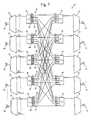
- the 4x4 switch arrangement shown in Fig. 12is representative of a north-south-east-west communication system.
- the nodes/switch arrangementscan be varied to accommodate various network configurations.
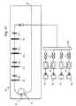
- a 3x3 arrangementis shown in Fig. 13 .
- the arrangements in Figs. 12 and 13show the cross connections of the switches 22, but do not show the waveband selectors within the switches 22.
- the flow of communication traffic between the nodescan take place using a variety of optical waveband hierarchies.
- the optical wavebandsare established and wavelengths assigned based on both the signal origination node and the signal destination node to avoid the need for wavelength conversion in the optical network.
- the spectrum of wavelengths used with each receivercan be divided into wavebands and the destination wavebands assigned to transmitters.
- the assignmentmay be static or dynamically controlled at the network management level so no overlap occurs in the wavebands assigned to each transmitter from the various receivers.
- Dynamic control of the waveband assignmentprovides flexibility in the wavelength management in the system 10 and can be performed at various points in the system, such as at the client system, e.g., SONET, SDH, ATM, IP interface with the optical network.
- Waveband hierarchies in which the origination and destination nodes are pairedare particularly useful in communication systems in which a signal is being sent from the origin to one destination, such as in telephone communication systems.
- the present inventioncan also accommodate the necessary protection systems to provide multiple paths to the same destination by proper allocation of the wavelengths.
- Waveband selectorscan be included in the switches 22 to pass signals corresponding to a particular source to any number of destination nodes.
- the switch 22can provide further control over the distribution of signals by passing broadcast signals to a distribution segment only upon a subscriber's request.
- the CATV providerin response to a programming request, can centrally control the switch to deliver the signal to the requester. In the absence of an express request by a subscriber the signal would not be broadcast to the segment. The limited availability of the signal on a segment may discourage pirating of programming signals.
- Switches 22 of the present inventioncan also be used for remote switching and routing of communication traffic in the event of a fault in the system. For example, in Fig. 12 if a signal were to travel from node A to node C, the typical path would be through the switch connected between nodes A and C. However, if a fault occurs in the line from the switch to node C, it may be desirable to route traffic from node A through node D to node C. Upon detection of the fault, the network management system could reconfigure the switches 22 in the system 10 to reroute the traffic or switch to a previously configured protection route.
- the present inventionprovides for flexibility in optical transmission systems.
- the present inventionprovides for increased transmission capacity without the commensurate increase in complexity that was present in the prior art systems.
Landscapes
- Engineering & Computer Science (AREA)
- Computer Networks & Wireless Communication (AREA)
- Signal Processing (AREA)
- Optical Communication System (AREA)
- Use Of Switch Circuits For Exchanges And Methods Of Control Of Multiplex Exchanges (AREA)
Description
- The present invention is directed generally to network, transmission and communication systems. More particularly, the invention relates to optical information network, transmission and communication systems and optical components, such as cross connect switches, add/drop devices, demultiplexers, and multiplexers, for use therein.
- The development of digital technology has provided electronic access to a vast amount of information. The increased access to information has fueled an increasing desire to quickly obtain and process the information. This desire has, in turn, placed ever increasing demands for faster and higher capacity electronic information processing equipment (computers) and transmission networks and systems linking the processing equipment (i.e., telephone lines, cable television (CATV) systems, local, wide and metropolitan area networks (LAN, WAN, and MAN)).
- In response to these demands, many transmission systems in use today either have been or will be converted from electrical to optical networks. Optical transmission systems provide substantially larger information transmission bandwidths than electrical systems, which provides for increased information transmission capacities.
- Early optical transmission systems were developed as space division multiplex (SDM) systems. In early SDM systems, one signal was transmitted as a single optical wavelength in each waveguide, i.e., fiber optic strand. A number of waveguides were clustered to form a fiber optic cable that provided for the transmission of a plurality of signals in spaced relationship.
- As transmission capacity demands increased, optical transmission and receiving equipment was developed that provided for time division multiplexed (TDM) transmission of a plurality of distinct optical signals in a single waveguide. Optical TDM systems are generally analogous to electrical TDM systems in that the signals are transmitted on a common line, but spaced in time. The transmission of the signals is in a known sequence allows the plurality of distinct signals to be separated after transmission.
- A problem with TDM transmission is the transmission bandwidth in the waveguide increases with each additional multiplexed signal. For example, information can be transmitted through a waveguide via a first series of optical signals separated in time by an interval Δt. Additional information can also be transmitted over the same waveguide using a second series of optical signals during the time interval Δt by merely offsetting the transmission of the first and second series of signals in time. While an optical signal in each series is only transmitted through the waveguide every Δt interval, two signals, or n signals in the general case, are passing through the waveguide during each interval. Therefore, the overall transmission rate in TDM systems increases directly with the number of signals transmitted.
- Signal transmission rates in fiber optic waveguides are generally limited by the interactions between the optical signal (i.e., light pulse) and microstructural features of the waveguide material. As the transmission rate is increased, signal dispersion in the fiber and other transmission effects deleterious to signal quality begin to occur as a result of the interactions.
- Optical signals are typically transmitted in wavelengths that minimize dispersion in the fiber. For example, older optical systems are commonly operated around 1310 nm and employ SMF-28 fiber manufactured by Corning, or its equivalent, which has minimum dispersion at or near 1310 nm. Another type of fiber, known as dispersion shifted fiber, has its minimum dispersion at or near 1550 nm. A third type of fiber sold by Corning as LS fiber and by Lucent Technology as TrueWave has its minimum dispersion at or near 1550 nm. In addition to having different minimum dispersion wavelengths, each fiber has varying immunity to other signal degradation mechanisms, such as four wave mixing, at increased transmission rates.
- The transmission rates at which the signal quality begins to degrade are substantially lower (< 40 Gbps) than the capacity of the transmission and receiving equipment. Therefore, TDM systems, which increase capacity by increasing transmission rates, generally have only a limited potential for further increasing the capacity of optical transmission systems.
- The development of wavelength division multiplex (WDM) transmission systems has provided a way to increase the capacity of optical systems without encountering the waveguide limitations present in TDM systems. In a WDM system, a plurality of optical signals including information carrying wavelengths are combined to produce a multiple wavelength signal that is transmitted through the system to a receiver. After the multiple wavelength signal is received, the information carrying wavelengths are separated from the multiple wavelength signal and provided to a corresponding plurality of destinations. Unlike TDM systems, only one WDM signal is transmitted during a time interval Δt, although each WDM signal contains a plurality of signals including information carrying wavelengths.
- Also unlike TDM systems, the waveguide material does not realistically limit the information bandwidth that can be placed on a single optical fiber in a WDM system. One skilled in the art can also appreciate that the number of wavelengths that can be used to transmit information over a single waveguide is currently limited by the complexity of the transmission and receiving equipment required to generate, transmit, receive, and separate the multiple wavelength signal.
- Currently, many optical transmission systems must convert the optical signal to an electrical signal during transmission to perform transmission functions, such as signal amplification and switching. The optical to electrical conversion, and vice versa, substantially limits the overall transmission speed of the network, and increases transmission losses in the network. Thus, it has been an industry goal to develop optical amplifiers and optical cross-connect switches to provide for high speed, all optical transmission systems.
- The development of optical fiber amplifiers produced by doping the optical fiber with Erbium ions (Er3+) or other elements has allowed for the elimination of electrical amplifiers and the requisite time delay and costs associated with signal conversion. In addition to simplifying and decreasing the cost of the equipment required to amplify a signal, optical fiber amplifiers have proven effective for amplifying a plurality of wavelengths without a commensurate increase in the complexity of the amplifier as additional wavelengths are included in the WDM signal.
- Unlike optical amplifiers, optical cross-connect switches greatly increase in complexity as the number of waveguides entering and exiting the switch and the number of wavelengths per waveguide increases. As a result, the expansion of all optical systems has been somewhat inhibited by the lack of simple, efficient, and economically attractive optical cross-connect switching systems.
- A number of optical cross-connect switches are based on one or more 1x2 signal splitters or 2x2 signal couplers used in conjunction with one or more wavelength filters, such as described in
U.S. Patent No. 5,446,809 issued to Fritz et al. The complexity of these types of switch increases not only with the number of inputs and outputs in the switch, but also with the number of wavelengths being switched. For example, if a 2x2 switch is provided to switch two eight wavelength WDM input signals to two output signals, the switch would have to include 32 gratings to allow all wavelengths to be switched. However, if a 4x4 switch is provided to switch four sixteen wavelength WDM input signals to four output signals, 256 gratings will be required. In addition, the flexibility of the switch is limited because additional gratings or filters must be added to each waveguide connecting each input to each output of the switch for every wavelength that is to be switched. - Another complication is that different signals entering a switch at different input ports will often times be carried by the same wavelengths. The use of common wavelengths frequently occurs because optical signals are generally transmitted using a relatively narrow range of wavelengths that have been established by optical standards committees with the goal of minimizing transmission losses in a waveguide and allowing equipment standardization in the industry.
- If two signals on a common wavelength from different inputs are switched to the same waveguide, both signals will be destroyed. The switch, therefore, must be designed to prevent the inadvertent destruction of signals transmitted to the switch on a common wavelength.
- Switches can be provided that "block" the switching of certain wavelengths to prevent destruction of two signals on a common wavelength. Switches can also be provided with wavelength converters that are used to change the wavelength of a signal, in lieu of blocking the signal, to prevent the destruction of the signal.
U.S. Patent No. 5,627,925 issued to Alferness et al. discloses an example of a switch that includes wavelength converters to provide a nonblocking switch. As expected, the use of wavelength converters adds a further degree of complexity to the design and function of optical cross-connect switches. - An alternative to adding wavelength converters to provide a nonblocking switch is to limit the wavelengths used in the system. For example,
U.S. Patent No. 4,821,255 issued to Kobrinski discloses an optical system employing transmission systems that transmit data at a different wavelength to each destination receiving system, i.e., N wavelengths for N receiving systems. In this manner, the optical system does not require a nonblocking switch and the assignment of a specific wavelength to each receiving system allows for a passive optical connection ("hard wire") between a transmission demultiplexer and a receiving multiplexer. - In addition, the same N wavelengths can be transmitted by each transmitting system if the receiving system is coordinated to receive a different wavelength from each transmitting system. Wavelength coordination eliminates the need for wavelength converters and allows the same transmitters and receivers to be used in the system.
- A difficulty with passive switching systems is that the streamlined nature renders the switch somewhat inflexible. For example, a specified wavelength is used to transmit signals between a transmission system and a receiving system. Therefore, it may be difficult to transmit multiple signals from one transmitting system to one receiving system at any one time. It is presumably possible to assign additional wavelengths to each of N transmitter/receiver combinations; however, for each wavelength added to each system, either N2 hard wire connections must be made.
- The problem of signal blockage can also be addressed by designing a system having excess transmission capacity. This would provide more available wavelengths than is required to meet current transmission requirements. However, in view of the continued expansion of communication networks the excess capacity may only be short term; therefore the ability to upgrade a system remains a desired feature of a switch.
- Similarly, other optical components, such as add/drop devices, demultiplexers and multiplexers, used in optical processing nodes between the transmitter and receivers increase in complexity and cost as additional channels are added to the system. In addition, these components most likely have to be replaced when a system is reconfigured or additional channels are to be added to the system.
- The continued advancement and development of communication systems is limited, at least in part, by the constraints placed upon optical systems by the current technology involved in optical processing systems. The elimination or reduction of these constraints is a primary concern of industry as the pace of communications continues to accelerate.
- Accordingly, there is a need for optical systems and optical components that allow for increased network capacity and flexibility. One aspect of which is to reduce the complexity of the equipment and increase the efficiency of the transmission system.
US 5,191,626 discloses an optical transmission system comprising an optical transmitter configured to transmit information via information carrying wavelengths, an optical receiver configured to receive the information transmitted via the information carrying wavelengths, and one optical processing node. This system also comprises controllable linear power dividers. However, this system does not overcome technical problems encountered when a high capacity processing of the information without increasing complexity is wanted.- This present invention proposes an optical transmission system according to
claim 1, a method of passing information to a destination according to claim 21, and an optical switch according to claim 25. - The apparatuses and methods of the present invention address the above needs and concerns for improved optical switches and systems. An optical transmission system of the present invention includes one or more optical signal transmitters and optical signal receivers optically communicating via one or more intermediate optical processing nodes. Each optical transmitter includes one or more optical sources, such as modulated lasers, and is configured to transmit information via one or more information carrying wavelengths. Each optical receiver is configured to receive one or more of the information carrying wavelengths using one or more various detection techniques, such as direct detection using optical wavelength filters and photodiodes, or indirect detection using coherent detectors.
- The intermediate optical processing nodes include optical switches, add and/or drop devices including at least one waveband selector configured to pass and substantially prevent the passage of optical wavebands that include a plurality of information carrying wavelengths from the transmitter to the receiver. The optical processing nodes provide for information management and processing in wavebands, instead of separating individual information carrying wavelengths from the signal and individually processing each wavelength. In this manner, high capacity processing of the information can be achieved without the prior complexities involved with increasing capacity. The processing of pluralities of individual wavelengths further provides for accommodating varying numbers and distributions of individual information carrying wavelengths in the system without having to reconfigure or replace system components.
- In an embodiment of the present invention, the optical processing node includes a switch providing cross connections between a plurality of transmitters and receivers. Optical signals including one or more information carrying wavelengths are transmitted to optical switch input ports and are distributed to optical switch output ports by splitting and/or waveband demultiplexing the optical signals depending upon the type of waveband selector used in the switch.
- Waveband selectors include at least one switch, gate, or filter, such as an erbium or mechanical switch, a Bragg grating, or a Mach-Zehnder or Fabry-Perot filter. The waveband selectors are generally configured to pass one or more optical wavebands from the input port to the output port in one mode and/or to substantially prevent the passage the optical wavebands in another mode. A signal is generally considered to be substantially prevented from passage, if the signal is sufficiently attenuated such that a remnant of the attenuated signal passing through the waveband selector does not destroy signals that have been selectively passed through the optical processing node. For example, a 40 dB attenuation of a signal will generally be sufficient to prevent cross-talk interference between remnant signals and signals passing through the optical processing node.
- In an embodiment, each input signal is waveband demultiplexed to separate the input signal into waveband signals. Each waveband signal is then split and each split waveband signal passed through a switch to a respective output port. In an embodiment, an erbium doped fiber is used as the switch in the waveband selector to pass, as well as to controllably amplify or attenuate, the split waveband signal to the output port when supplied with optical pump power. In the absence of pump power, the erbium fiber absorbs the waveband signal, which substantially prevents the passage of the signal. One or more optical combiners are provided at the output ports to combine split waveband signal from the waveband selector passing optical wavebands from the input ports.
- The optical signal at each input port can also be demultiplexed according to a known destination of each waveband signal and the waveband signal is passed to the output port corresponding to the destination. The optical signals can be transmitted to the switch in wavelengths that are unique to the signal destination to avoid the use of wavelength converters in the optical system.
- Bragg gratings, either reflective or transmissive, can be included in the waveband selector to switch any number of wavebands. The Bragg gratings of the present invention include one grating produced to reflect an entire waveband or a series of gratings operated in concert that piecewise correspond to the waveband. In an embodiment, tunable permanent Bragg gratings can be provided corresponding to each of the wavebands to allow for dynamic reconfiguration of the switch.
- In addition, the optical processing node can include transient gratings to provide for additional reconfiguration of the processing node. Transient grating can be formed in the waveguide either by induction using a coupled circuit or via a writing circuit integrated with the transmission fiber.
- In an embodiment of the optical transmission system, pluralities of nodes are interconnected to form a network. The nodes may contain optical transmitters, receivers, add and/or drop devices/ports, and/or switching equipment depending upon whether the node is an origination and/or a destination node, and whether it is a terminal or an intermediate node. In an embodiment, the network management system is provisioned to assign wavelengths to information that can be transmitted to destination nodes in a manner to obviate the need for wavelength conversion at the optical switch. Wavelength assignment can be static or dynamically performed via a network management system, for example, at the client system interface with the optical network. The optical switches cross connecting the nodes and add and/or drop ports are configured to respectively switch and add/drop the information carrying wavelengths in wavebands without separately switching the individual wavelengths.
- Accordingly, the present invention addresses the aforementioned problems and provides apparatuses and methods to increase the efficiency and capacity of optical communication systems. These advantages and others will become apparent from the following detailed description.
- Embodiments of the present invention will now be described, by way of example only, with reference to the accompanying Figures wherein like members bear like reference numerals and wherein:
Figs. 1-4 depict optical communication systems of the present invention;Figs. 5-8b depicts waveband selectors of the present invention;Figs. 9-11 depict transient grating waveband selectors of the present invention; and,Figs. 12-13 depict multi-node optical communication networks of the present invention.- The operation of
optical systems 10 of the present invention will be described generally with reference to the drawings for the purpose of illustrating embodiments only and not for purposes of limiting the same. - Generally, the
optical system 10 includes at least oneoptical transmitter 12 and at least oneoptical receiver 14, as shown inFig. 1 . Eachtransmitter 12 is configured to transmit information via one or moreinformation carrying wavelengths 18i,k contained in at least onewaveband 161,i to thereceivers 14. Eachreceiver 14 is configured to receive the information carried via one or more of theinformation carrying wavelengths 18i,k. As used herein, the term "information" should be broadly construed to include any type of data, instructions, or signals that can be optically transmitted. - As shown in
Fig. 1 , thesystem 10 further includes at least one intermediateoptical processing node 20, such as anoptical switch 22. Thetransmitter 12 is configured to transmit anoptical signal 24 containing one or moreinformation carrying wavelengths 18j along signal transmission waveguide, i.e., fiber, 26 to theswitch 22 viainput port 28. Theoptical processing node 20 includes one or more waveband selectors, or selective element, 30 that are configured to pass and/or substantially prevent the passage of information inwavebands 16i to thereceiver 14 viaoutput ports 32. Because the information is being manipulated in wavebands, the individualinformation carrying wavelengths 18j within thewaveband 16i do not have to be separated in individual wavelengths to be managed and processed. Also, theindividual wavelengths 18j within thewaveband 16i be varied in thesystem 10 without affecting the configuration of theoptical processing node 20.Wavelengths 18j in theoriginal signal 24 but not within thewaveband 16i are prevented from passing through to thereceivers 14. - In the present invention,
optical signals 24 can be produced including a number ofwavebands 16, each of which may contain one or more information carrying wavelengths in a continuous band of wavelengths or a plurality of wavelength bands. For example, awaveband 16 can be defined as having a continuous range of -200 GHz containing 20 differentinformation carrying wavelengths 181-20 spaced apart on a 10 GHz grid. The bandwidth of each waveband can be uniformly or variably sized depending upon the network capacity requirements. Likewise, the bandwidth of the waveband is not restricted, but can be varied to accommodate varying numbers of wavelengths. - Generally,
systems 10 of the present invention are configured so that the optical processing nodes do not separate and process individual information carrying wavelengths during transmission from the transmitter to the receiver. Instead,optical processing nodes 20 are configured to process the information in wavebands that may include any number of individual information carrying wavelengths. The processing of information in wavebands decreases the complexity involved in processing large numbers of channels, while increasing the flexibility of optical components deployed in the transmission path between transmitters and receivers. The bandwidth and number of information carrying wavelengths within a waveband in a network can be statically or dynamically allocated depending upon the information traffic flow in a given network segment. Fig. 2 shows a more general arrangement of thesystem 10, which includes a plurality oftransmitter 12n optically connected via theswitch 22 to a plurality ofreceiver 14m. Analogous toFig. 1 , eachtransmitter 12n transmits anoptical signal 24n which includes one ormore wavelengths 18n,j through awaveguide 26n to aninput port 28n of theswitch 22. It will be appreciated that each transmitter may include one or more sources to transmit and one or more wavelength signals. Likewise, each receiver may include one or more detectors for receiving the signals.- An
optical distributor 34n, such as ademultiplexer 36 and/or asplitter 38, is provided in theinput port 28n to distribute thesignal 24n to thewaveband selectors 30n,m. Anoptical combiner 40m, such as awavelength division multiplexer 42 or acoupler 44, is generally included to combine thewavelengths 18m,k inwaveband 16m,i emerging from thewaveband selectors 30n,m and provide a modified signal 24'm. The modified signal 24'm exits the switch through theoutput port 32m and passes alongwaveguide 26 to thereceiver 14m. - For convenience and clarity,
Fig. 2 shows only awaveband selector 30 connectinginput port 281 tooutput port 321. However, it should be understood that theswitch 22 will generally include at least onewaveband selector 30 between eachinput port 28 and eachoutput port 32. It is also noted that in some networks it is not necessary that corresponding input and output ports, e.g. 281 and 321, be connected to loop a signal back to its point of transmission. In addition, reference numeral subscripts are generally not used in the remainder of the description to simplify the nomenclature. Transmitters 12 used in thesystem 10 can include one or more optical emitters and sources that provide continuous wave and/or pulsed beams, such as one or more modulated lasers as is known in the art. Thetransmitter 12 may also include narrow band incoherent sources such as described inU.S. Patent Nos. 5,191,586 and5,268,910 issued to Huber or other optical sources for producing optical signals. Information can be directly or indirectly, e.g., externally, modulated, or alternatively upconverted, onto an optical wavelength, and the information itself may be a time division multiplexed signal.- The
transmitter 12 can also be used to provide multiple information carrying wavelengths using techniques such as described inU.S. Patent No. 5,400,166 . Multiple information carrying wavelengths can be placed on a single carrier from thetransmitter 12 using techniques, such as subcarrier modulation (SCM). SCM techniques are described inU.S. Patent Nos. 5,101,450 ,5,134,509 ,and5,301,058 issued to Olshansky ,4,989,200 issued to Olshansky et al. ,5,432,632 issued to Watanabe and5,596,436 issued to Sargis et al. - The
transmitters 12 may be coupled to an external electrical network or part of an optical-electrical-optical (O/E/O) signal regenerator within an optical network. One skilled in the art will appreciate that the selection of thetransmitter 12 and the number of information carrying wavelengths will depend upon the desired information transfer rates for a particular transmitter/receiver system at the respective nodes. While the present invention provides the ability to substantially upgrade the transfer rate for the node, it does not require that older, slower nodes be upgraded upon implementation of the present invention. - Consistent with the discussion regarding the
transmitter 12, thereceiver 14 andtransmission fiber 26 does not have to be upgraded to be compatible with the present invention. In the present invention, the capabilities of the receiving system can be taken in account when establishing wavebands to be transmitted to aparticular receiver 14. - As shown in
Fig. 3 , thereceiver 14 will generally be used to separate the individualinformation carrying wavelengths 18i,k in eachwaveband 16i contained in the modified signal 24' and convert the information to one or more electrical signals. The receiver may include a number of a wavelength filters, such as Bragg gratings or demultiplexers, in combination with an optical to electrical converter (O/E), such as a photodiode, to provide for direct detection of the individual wavelengths. Thereceiver 14 may also provide for indirect detection of the individual wavelengths, such as by using coherent detector arrangements. - Referring to
Fig. 4 , thesystem 10 may include other types ofintermediate processing nodes 20, such as add and/or drop devices. The other intermediate processing nodes can be employed to selectively modify the wavebands in the signal 24' and pass a further modifiedsignal 24" tosuccessive switches 22 and to thereceivers 14. The subsequent switches 22 between otherintermediate processing nodes 20 and thereceivers 14 can be used to further process thesignal 24" to produce a further modifiedsignal 24"' which may includewaveband subset 16i1. The optical add and/or drop devices/ports can be embodied as a 2x2 switch that can provide for 100% programmable add/drop capability or by employing directional devices, such as couplers and/or circulators, with or withoutwaveband selectors 30 to provide varying degrees of programmability, as will be further discussed. - The
receiver 14 can also be used to further distribute thesignal 24"' as a part of an O/E/O signal regenerator. One skilled in the art will appreciate that in an O/E/O regenerator the optical wavelengths received by thereceiver 14 do not necessarily have to correspond to the optical wavelengths at which the information is further transmitted. Waveband selectors 30 generally include at least one filter, gate, and/or switch configured to pass and/or substantially prevent the passage of at least onewaveband 16 received from theinlet port 28 to theoutlet port 32. A signal is generally considered to be substantially prevented from passage, if the signal is sufficiently attenuated such that a remnant of the attenuated signal that passes through the waveband selector does not destroy signals that have been selectively passed through theoptical processing node 20. For example, a 40 dB attenuation of a signal will generally be sufficient to prevent cross-talk interference between remnant signals and signals being selectively passed through theoptical processing node 20.- In an embodiment shown in
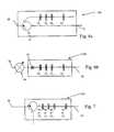
Fig. 5 , theswitch 22 includes awaveband demultiplexer 36 and anoptical signal splitter 38 coupled via a dopedoptical fiber 46 to themultiplexer 42 at theoutput port 32. When an optical signal is to be passed to theoutput port 32, the doped fiber is supplied with energy from theswitch pump 48 to overcome the absorption of the dopedfiber 46. The amount of energy supplied by thepump 48 can be controlled to selectively amplify or attenuate a signal being passed through thewaveband selector 30. In the absence of optical pump energy, the dopedfiber 46 will absorb the optical signal, thereby substantially preventing the passage of that portion of the signal to theoutlet port 32. In the embodiment ofFig. 5 , the wavebands can be switched to any number of output ports including one to one switching and one to many broadcasting. - The dopant in the doped
optical fiber 46 can be erbium or any other dopant including other rare earth elements that can render the fiber transmissive in one state and substantially less transmissive in another state. The selection of a dopant in the doped fiber will depend upon the information carrying wavelengths that are to be switched in the system. Also, mechanical, electro-optic, liquid crystal, semiconductor, and other types of switches along with gratings, filters and gates, can be substituted for or used in combination with dopedfiber 46 to achieve desired characteristics in theswitch 22. - The
waveband selector 30 may include reflective (≥50% reflectance) and/or transmissive (≥50% reflectance) selective elements that can be used to pass, either reflect or transmit, any of thewavebands 16 that comprise thesignal 24. Thewaveband selector 30 may employ Mach-Zehnder filters, Fabry-Perot filters, and Bragg gratings to perform the waveband selection. - As shown in
Figs. 6 and 7 ,waveband selectors Fig. 5 ) and/or transmissive Bragg gratings 52 (Fig. 6 ) to pass selected wavebands to theoutput ports 32. Each grating, 50 and 52, can be provided to pass selected wavebands tooutput ports 32. Alternatively, thewaveband selector 30 may include a series of multiple Bragg gratings that provide for piecewise coverage of the waveband. In the case of a multiple grating waveband selector, some separation of the wavelengths in the waveband will occur between gratings, but the multiple gratings are collectively operated to pass or substantially prevent the passage of the waveband. The multiple grating selector can be tuned to individual idler gaps or telescoped to one or more common idler gaps to decrease the idler gap bandwidth. - The number of gratings in
Figs. 6 and 7 is shown as being equal to the number ofwavebands 16 being switched. However, the number of selectors provided in the switch does not necessarily have to correspond to number ofwavebands 16 currently in the system. For example, the configurations shown inFigs. 5-11 may also be suitable for use in add/drop multiplexers, as well as demultiplexers or multiplexers, in which any number of wavebands can be processed. - It may also be advantageous to provide sub-wavebands within the
wavebands 16 of varying size that can be received, divided into the sub-wavebands, and the sub-wavebands can further transmitted to other receivers within the system. Thewaveband selectors 30 can also be used to pass multiple wavebands to reduce the number of components in thesystem 10. In addition, thewavebands 16 can be selected to overlap to allow one ormore wavelengths 18 to be transmitted inmultiple wavebands 16. - As shown in
Fig. 6a , awaveband selector 130 can include a threeport circulator 54 used in conjunction with the plurality ofreflective Bragg gratings 50 using a configuration similar those discussed inU.S. Patent Nos. 5,283,686 and5,579,143 issued to Huber , and5,608,825 issued to Ip . InFig. 6b , awaveband selector 230 employstransmissive gratings 52 to transmit selected wavebands to theoutput ports 32 and reflect the remaining wavebands. Anoptical isolator 56 can be incorporated to prevent reflected wavebands from propagating back to theinput ports 28. One skilled in the art will appreciate that directional couplers and other directional devices can be substituted for the optical circulators with appropriate circuit modifications. - The
optical processing node 20 may include awavelength converter 58 to provide for switching one of more of the wavelengths in the transmittedsignal 24. InFig. 6a , thewavelength converter 58 is shown before thewaveband selector 30; however, thewavelength converter 58 may also be positioned after thewaveband selector 30 and operated accordingly. - Similarly in
Fig.7 , awaveband selector 330 can be used with one or more directional devices, such as a circulator or a coupler, with either reflective or transmissive waveband gratings, 50i or 52i, to select wavebands. It will be appreciated that theselector 330 can be employed as an add and/or drop device/port, as well as a filter or in a demultiplexer or multiplexer in thesystem 10. - The
optical distributor 34 associated with theinput port 28 can be embodied as an optical splitter to split thesignal 24 and distribute a portion of theentire signal 24 to each of theoutput ports 32. As shown inFig. 8a , theoptical distributor 34 can be embodied as acirculator 54 to provide the entire signal to eachwaveband selector 430. Wavelengths within waveband of theselector 230 are transmitted to theoutput port 32, while the remaining wavelengths are reflected by the transmissive gratings and circulated to successive ports. - Likewise, optical couplers can serve as the
distributor 34 to provide the entire signal to waveband selector 530 (Fig. 8b ). One skilled in the art will appreciate that directional devices, such as multiple three port circulators and/or coupler, can be cascaded in various other configurations equivalent to those shown inFigs. 8a &b. The gratings, 50 or 52, could be prepared having a reflectivity and transmittance of less than 100%, to allow a portion of signal to be transmitted and reflected. - The
fiber Bragg gratings switch 22 can be permanently and/or transiently produced. Embodiments of the present invention incorporate fixed and/or tunable permanent Bragg gratings, 50 and 52 as thewaveband selectors 30. The permanent gratings used in the present invention can be prepared by conventional methods, such as by using ultraviolet (UV) light to irradiate a GeO2 doped fiber core. Such methods are discussed inU.S. Patent Nos. 4,725,110 issued to Glenn et al. ,5,218,655 and5,636,304 issued to Mizrahi et al. , which are incorporated herein by reference, and related patents. - The permanent gratings can be tuned to provide for reflectance of a waveband in one mode and transmittance in another mode. Tuning of the grating properties can be accomplished mechanically (stretching), thermally, or optically, such as discussed in
U.S. Patent Nos. 5,007,705 ,5,159,601 , and5,579,143 , and byM. Janos et al., Electronics Letters, v32, n3, pp. 245-6, electronically, or in some other appropriate manner. - A limitation of tunable permanent gratings is that a portion of the wavelength band can not be used to transfer signals. The unused portion of the wavelength band, called an "idler" gap, is necessary to provide each permanent grating with a gap in the wavelength spectrum in which the grating will not affect a signal encountering the grating.
- Transient reflective or transmissive gratings, 50T and 52T, respectively, could also be used in the
waveband selector 30. Transient gratings can be used to reduce or eliminate the need for idler gaps in the transmission wavelengths and provide increased flexibility in the wavelength selectivity of theswitch 22. - Transient gratings, either 50T or 52T, can be formed in a portion of the fiber in which the refractive index of the fiber can be transiently varied to produce a grating. In an embodiment, the fiber portion is doped with Erbium, other rare earth elements, such as Yb and Pr, and/or other dopants that can be used to vary the refractive index of the fiber to produce a grating. In another embodiment, the transient grating can be formed in a fiber section that contains a permanent grating to provide a combined performance grating and/or to establish a default grating in the absence of the transient grating.
- As shown in
Figs. 9-11 , transient gratings can be written by introducing a grating writing beam either directly into the transmission fiber or by coupling the writing beam into the transmission fiber. One or more transientgrating writing lasers 60i are used to introduce a transient grating writing beam into the doped portion of thesignal waveguide 26. In awaveband selector 630 shown inFig. 9 , the writing beam is split into two paths and introduced into thetransmission fiber 26 viaports 62. A plurality of narrow wavelengthreflective gratings 64i are positioned in one of the writing beam paths to control the position of the standing wave in thewaveguide 26 by introducing a time delay on the wavelengths of the writing beam. Narrow wavelength reflective or transmissive gratings, 64i or 66i, can also be used to remove the writing beam from thetransmission fiber 26. - As shown in
Fig. 10 , the writing beam can also be reflected back upon itself using spaced narrow wavelengthreflective gratings 64i, to form a standing wave and produce atransient gratings 50T inwaveband selector 730. Thegrating writing lasers 60i can be operated in conjunction withmodulators 68 and pulsing switches 70 to control the coherence of the writinglasers 60i and the resultingtransient gratings 50Ti. Awaveband selector 830, shown inFig. 11 , can also be configured with areflector 72 in a coupled fiber to establish a standing wave by reflecting the writing beam back upon itself to form the standing wave in a manner similar to that described with respect toFig. 10 . - Single wavelength continuous writing beam arrangements have been used for signal identification and pattern recognition as discussed byWey et al., "Fiber Devices for Signal Processing", 1997 Conference on Lasers and Electro-Optics, Baltimore, MD. Also,
U.S. Patent No. 5,218,651 issued to Faco et al. , which is incorporated herein by reference, describes two beam methods for producing a transient Bragg grating in a fiber. - In
systems 10 of the present invention, theswitch 22 can be used to optically connect a transmitter and a receiver (Fig. 1 ) in a 1x1 configuration or a plurality ofnodes 100 in an nxm configuration (Figs. 12-13 ). In a 1x1 configuration, theswitch 22 can be useful for dropping wavebands or for varying the waveband characteristics (gain trimming) of the signal. - The
nodes 100 used in thesystem 10 may contain various system components including optical transmitters, receivers, and/or other processing equipment, such as switches depending upon whether the node is an origination (transmitting signals) and/or a destination (receiving signals) node, and whether is is a terminal node. Thesystem 10 may further include other optical transmission equipment, such asoptical amplifiers 74, and otheroptical processing nodes 20, such as optical add/drop multiplexers, between the switches and thenodes 100 as may be useful in a given system. - The 4x4 switch arrangement shown in
Fig. 12 is representative of a north-south-east-west communication system. One skilled in the art will appreciate that the nodes/switch arrangements can be varied to accommodate various network configurations. For example, a 3x3 arrangement is shown inFig. 13 . The arrangements inFigs. 12 and13 show the cross connections of theswitches 22, but do not show the waveband selectors within theswitches 22. - The flow of communication traffic between the nodes can take place using a variety of optical waveband hierarchies. In an embodiment, the optical wavebands are established and wavelengths assigned based on both the signal origination node and the signal destination node to avoid the need for wavelength conversion in the optical network.
- For example, the spectrum of wavelengths used with each receiver can be divided into wavebands and the destination wavebands assigned to transmitters. The assignment may be static or dynamically controlled at the network management level so no overlap occurs in the wavebands assigned to each transmitter from the various receivers. Dynamic control of the waveband assignment provides flexibility in the wavelength management in the
system 10 and can be performed at various points in the system, such as at the client system, e.g., SONET, SDH, ATM, IP interface with the optical network. - Waveband hierarchies in which the origination and destination nodes are paired are particularly useful in communication systems in which a signal is being sent from the origin to one destination, such as in telephone communication systems. In addition, the present invention can also accommodate the necessary protection systems to provide multiple paths to the same destination by proper allocation of the wavelengths.
- In a multiple destination system, such as a cable television system, it may be more appropriate for the wavebands to be determined based solely on the origination node of the signal. Waveband selectors can be included in the
switches 22 to pass signals corresponding to a particular source to any number of destination nodes. Theswitch 22 can provide further control over the distribution of signals by passing broadcast signals to a distribution segment only upon a subscriber's request. The CATV provider, in response to a programming request, can centrally control the switch to deliver the signal to the requester. In the absence of an express request by a subscriber the signal would not be broadcast to the segment. The limited availability of the signal on a segment may discourage pirating of programming signals. Switches 22 of the present invention can also be used for remote switching and routing of communication traffic in the event of a fault in the system. For example, inFig. 12 if a signal were to travel from node A to node C, the typical path would be through the switch connected between nodes A and C. However, if a fault occurs in the line from the switch to node C, it may be desirable to route traffic from node A through node D to node C. Upon detection of the fault, the network management system could reconfigure theswitches 22 in thesystem 10 to reroute the traffic or switch to a previously configured protection route.- As can be seen, the present invention provides for flexibility in optical transmission systems. In addition, the present invention provides for increased transmission capacity without the commensurate increase in complexity that was present in the prior art systems.
- Those of ordinary skill in the art will appreciate that numerous modifications and variations that can be made to specific aspects of the present invention without departing from the scope of the present invention. It is intended that the foregoing specification and the following claims cover such modifications and variations.
Claims (26)
- An optical transmission system (10) comprising :at least one optical transmitter (12) configured to transmit information via a plurality of information carrying wavelengths;at least one optical receiver (14) configured to receive the information transmitted via the a plurality of information carrying wavelengths; and,characterised in that the optical transmission system further comprises at least one optical processing node (20) including at least one waveband selector (30) configurable to in a mode selectively pass and in another mode substantially prevent the passage of at least one optical waveband comprised of a plurality of information carrying wavelengths from at least one of said at least one transmitters (12) to at least one of said at least one receivers (14),wherein said at least one optical processing node (20) includes an optical switch (22) having input ports (28) corresponding to said at least one transmitter (12) and output ports (32) corresponding to said at least one receiver (14) and said information carrying wavelengths are switched from said input ports (28) to said output ports (32) in said at least one optical waveband by said at least one waveband selector (30),wherein said switch (22) includesa waveband demultiplexer (36) corresponding to each input port (28) and configured to receive and separate an optical signal containing the plurality of information carrying wavelengths into separate optical wavebands signals,an optical splitter (38) in optical communication with and corresponding to each of the separated waveband signals from each of said optical demultiplexers (36), each of said optical splitters (38) configured to split the separated waveband signals into a number of split waveband signals corresponding to each output port (32),said at least one said waveband selectors (30) being positioned to receive each split waveband signal and configurable to in said a mode pass and in said another mode to substantially prevent the passage of the split waveband signal to said corresponding output port (32), andan optical combiner (40) corresponding to each output port (32) and configured to receive the split waveband signals from each of said waveband selectors (30) corresponding to said output port (32) and provide a combined optical waveband signal to said output port (32),wherein at least one said waveband selectors (30) includes a doped optical fiber (46) configured to allow an optical waveband to pass through the fiber in one mode and to substantially prevent the passage of the optical waveband through the fiber in another mode, wherein said doped optical fiber (46) includes an erbium doped fiber coupled to an optical energy pump source (48), the erbium fiber (46) being configured to substantially prevent the passage of the optical waveband signal when said fiber (46) is not pumped with optical energy from said optical energy pump source (48) and to allow said optical waveband signal to substantially pass through the fiber (46) when pumped with optical energy from said pump source (48).
- The optical transmission system (10) of claim 1, wherein said at least one waveband selector (30) is configured to in said a mode selectively pass and in said another mode substantially prevent the passage of said at least one optical waveband without separating said plurality of information carrying wavelengths into individual information carrying wavelengths.
- The optical transmission system (10) of claim 1 wherein said optical energy pump source (48) is configured to control the intensity of the optical waveband passing through the fiber (46) by varying the optical energy pumped into the erbium doped fiber (46).
- The optical transmission system (10) of claim 1 wherein at least one of said waveband selectors (30) is selected from the group consisting of doped fiber, mechanical, electro-optic, liquid crystal switches, semiconductor, and combinations thereof, in which said switch (22) can be operated to pass at least one waveband in one mode and substantially prevent the passage of said at least one waveband in another mode.
- The optical transmission system (10) of claim 1, wherein said at least one optical processing node (20) includes an optical add/drop device containing said at least one waveband selector (30) to selectively add an optical waveband to be transmitted to said at least one receiver (14) and to selectively drop an optical waveband transmitted by said at least one transmitter (12).
- The optical transmission system (10) of claim 1, wherein said at least one optical processing node (20) includes ports selected from the group consisting of add devices, drop devices and combinations thereof.
- The optical transmission system (10) of claim 1, wherein said at least one optical processing node (20) includes a demultiplexer (36) configured to receive the information carrying wavelengths from said at least one transmitter (12) and distribute the information carrying wavelengths in optical wavebands to at least one of said at least one receivers (14).
- The optical transmission system (10) of claim 1, wherein said at least one optical processing node (20) includes a multiplexer (42) configured to receive optical wavebands passed by said at least one waveband selector (30) and provide a multiple optical waveband signal to said at least one receiver (14).
- The optical transmission system (10) of claim 1 wherein said at least one waveband selector (30) includes transmissive and reflective waveband selectors (30) selected from the group consisting of optical filters, Bragg gratings, gates, switches and combinations thereof.
- The optical transmission system (10) of claim 1 wherein said at least one waveband selector (30) includes an optical waveguide configured to provide for the formation of an optical grating therein.
- The optical transmission system (10) of claim 1 wherein said at least one waveband selector (30) includes a permanent Bragg grating selected from the group consisting of transmissive and reflective operated permanent gratings (52,50).
- The optical transmission system (10) of claim 1 wherein said at least one waveband selector (30) includes a tunable grating.
- The optical transmission system (10) of claim 12 wherein said tunable grating is selected from the group consisting of mechanically, thermally, optically, and electronically tunable gratings, and combinations thereof.
- The optical transmission system (10) of claim 1 wherein said at least one waveband selector (30) includes an optical circulator (54) having a first port optically connected to said at least one transmitter (12), a second port optically connected between said first port and a reflective grating configured to reflect said at least one waveband and a third port optically connected to pass a reflected waveband from said reflective grating to said at least one receiver (14).
- The optical transmission system (10) of claim 1 wherein said at least one waveband selector (30) includes an optical circulator (54) having a first port optically connected to said at least one transmitter (12), a second port optically connected to said first port and a transmissive grating configured to transmit said at least one waveband from said second port to said at least one receiver (14).
- The optical transmission system (10) of claim 1 wherein :said at least one optical receiver (14) includes a plurality of optical receivers (14i);said at least one optical transmitter (12) includes a plurality of optical transmitters (12i); and,said optical processing node (20) includes a switch optically connecting said transmitters (12i) and said receivers (14i) and configured to pass optical wavebands of information from said transmitters (12i) to said receivers (14i).
- The optical transmission system (10) of claim 1 wherein said optical processing node (20) is configurable to provide any of one or more wavebands from any of said at least one transmitters (12i) to any of said at least one receivers (14i).
- The optical transmission system (10) of claim 1, further comprising :a demultiplexer (36) corresponding to each of said at least one transmitters (12i) and configured to receive and separate the plurality of individual information carrying wavelength signals ; and,a plurality of wavelength converters (58) optically connecting said demultiplexer (36) and said at least one waveband selector (30) and configured to convert the plurality of information carrying wavelength signals from said demultiplexer (36) into information carrying wavelengths within said at least one waveband.
- The optical transmission system (10) of claim 1 wherein said at least one transmitter (12) includes at least one modulated laser for providing said plurality of information carrying wavelengths and said receiver (14) includes a plurality of photodiodes corresponding to said plurality of information carrying wavelengths in said at least one optical waveband.
- The optical transmission system (10) of claim 1 wherein said at least one waveband selector (30) comprises an in fiber Bragg grating configured to selectively pass said optical waveband including said plurality of information carrying wavelengths.
- A method of passing information to a destination comprising :producing an optical signal comprised of a plurality of information carrying wavelengths;transmitting the optical signal from at least one optical transmitter (12) to at least one optical receiver (14); and,
using at least one optical node (20) which includes at least one waveband selector (30) to in a mode selectively pass and in another mode substantially prevent the passage of at least one optical waveband of the optical signal comprised of a plurality of information carrying wavelengths from at least one of said transmitters to a destination in the form of at least one of said receivers without separating the individual information carrying wavelengths.the method further comprising :assigning a waveband comprised of a band of wavelengths to at least one destination;providing an optical processing node (20) containing a waveband selector (30) configured to pass the waveband of information to the at least one destination without separating the individual information carrying wavelengths in the waveband ;producing an optical signal including a plurality of information carrying wavelengths within the assigned waveband;transmitting the optical signal to the optical processing node (20) ; and,characterised inpassing the optical signal through waveband selector (30) in the optical processing node (20) to selectively pass the assigned waveband of information to the at least one destination without separating the individual wavelengths,wherein said passing includes providing a pumped erbium doped fiber (46) in the waveband selector (30) to selectively pass assigned wavebands to the at least one destination. - The method of claim 21 further comprising
separating the information carrying wavelengths from the waveband at the destination into individual information carrying optical wavelengths ; and,
reproducing the information contained in the information carrying wavelengths in electronic form. - The method of claim 22 wherein said passing includes providing a Bragg grating to selectively reflect or transmit the optical waveband of information to the destination.
- The method of claim 23 wherein said passing includes providing at least one grating selected from the group consisting of reflective and transmissive gratings and combinations thereof in the waveband selector (30) to selectively pass assigned wavebands to the at least one destination.
- An optical switch (22) comprising :at least one input port (28);at least one output port (32); and,at least one waveband selector (30) providing optical communication between said at least one input port and said at least one output port (32),characterised in that said at least one waveband selector (30) is configurable to in a mode pass and in another mode substantially prevent the passage of information in at least one optical waveband between said at least one input port (28) and said at least one output port (32), and at least one of said at least one optical wavebands includes a plurality of information carrying wavelengths,wherein said at least one optical processing node (20) includes an optical switch (22) having input ports (28) corresponding to said at least one transmitter (12) and output ports (22) corresponding to said at least one receiver (14) and said information carrying wavelengths are switched from said input ports (28) to said output ports (22) in said at least one optical waveband by said at least one waveband selector (30),wherein said switch (22) includesa waveband demultiplexer (36) corresponding to each input port (28) and configured to receive and separate an optical signal containing the plurality of information carrying wavelengths into separate optical wavebands signals,an optical splitter (38) in optical communication with and corresponding to each of the separated waveband signals from each of said optical demultiplexers (36), each of said optical splitters (38) configured to split the separated waveband signals into a number of split waveband signals corresponding to each output port (32),at least one said waveband selectors (30) being positioned to receive each split waveband signal and configurable to in a mode pass and to in another mdoe substantially prevent the passage of the split waveband signal to said corresponding output port (32), andan optical combiner (40) corresponding to each output port (32) and configured to receive the split waveband signals from each of said waveband selectors (30)corresponding to said output port (32) and provide a combined optical waveband signal to said output port (32),wherein at least one said waveband selectors (30) includes a doped optical fiber (46) configured to allow an optical waveband to pass through the fiber in a mode and to substantially prevent the passage of the optical waveband through the fiber in another mode, wherein said doped optical fiber (46) includes an erbium doped fiber coupled to an optical energy pump source (48), the erbium fiber (46) being configured to substantially prevent the passage of the optical waveband signal when said fiber (46) is not pumped with optical energy from said optical energy pump source (48) and to allow said optical waveband signal to substantially pass through the fiber (46) when pumped with optical energy from said pump source (48).
- The optical switch (22) of claim 25 wherein said at least one waveband selector (30) is configured to information carrying wavelengths only as a part of said at least one optical waveband.
Applications Claiming Priority (3)
| Application Number | Priority Date | Filing Date | Title |
|---|---|---|---|
| US119562 | 1993-09-13 | ||
| US09/119,562US6449073B1 (en) | 1998-07-21 | 1998-07-21 | Optical communication system |
| PCT/US1999/016485WO2000005832A1 (en) | 1998-07-21 | 1999-07-21 | Optical communication systems, apparatuses, and methods |
Publications (3)
| Publication Number | Publication Date |
|---|---|
| EP1099321A1 EP1099321A1 (en) | 2001-05-16 |
| EP1099321A4 EP1099321A4 (en) | 2007-05-02 |
| EP1099321B1true EP1099321B1 (en) | 2012-12-26 |
Family
ID=22385075
Family Applications (1)
| Application Number | Title | Priority Date | Filing Date |
|---|---|---|---|
| EP99937360AExpired - LifetimeEP1099321B1 (en) | 1998-07-21 | 1999-07-21 | Optical communication systems, apparatuses, and methods |
Country Status (3)
| Country | Link |
|---|---|
| US (1) | US6449073B1 (en) |
| EP (1) | EP1099321B1 (en) |
| WO (1) | WO2000005832A1 (en) |
Families Citing this family (43)
| Publication number | Priority date | Publication date | Assignee | Title |
|---|---|---|---|---|
| US6771905B1 (en)* | 1999-06-07 | 2004-08-03 | Corvis Corporation | Optical transmission systems including optical switching devices, control apparatuses, and methods |
| AUPQ617500A0 (en)* | 2000-03-10 | 2000-04-06 | Telstra R & D Management Pty Ltd | A communications network architecture |
| FR2812988B1 (en) | 2000-08-10 | 2005-06-24 | Cit Alcatel | OPTICAL SIGNAL SWITCH |
| US7145704B1 (en) | 2003-11-25 | 2006-12-05 | Cheetah Omni, Llc | Optical logic gate based optical router |
| WO2002087277A2 (en)* | 2001-02-08 | 2002-10-31 | Corvis Corporation | Optical transmission systems including multi-casting systems, apparatuses, and methods |
| EP1368924A4 (en)* | 2001-03-16 | 2010-01-06 | Meriton Networks Us Inc | Method and apparatus for transferring wdm signals between different wdm communications systems in optically transparent manner |
| KR100399049B1 (en)* | 2001-04-16 | 2003-09-26 | 한국전자통신연구원 | High wavelength selector, and multi-channel selector for space and wavelength in high speed optical integrated circuit using the High wavelength selector |
| US6636651B2 (en)* | 2001-06-08 | 2003-10-21 | Koncent Communication, Inc. | Four-port bidirectional optical circulator |
| US20020186434A1 (en)* | 2001-06-08 | 2002-12-12 | Roorda Peter David | Transparent photonic switch architectures for optical communication networks |
| US20030039003A1 (en)* | 2001-08-27 | 2003-02-27 | Bogdan Jakobik | Architectural arrangement for core optical networks |
| DE60202415T2 (en)* | 2001-09-10 | 2006-01-12 | Jds Uniphase Inc., Ottawa | Optical wavelength-selective switch without distortion of the unblocked channels |
| US7260655B1 (en) | 2001-12-03 | 2007-08-21 | Cheetah Omni, Llc | Optical routing using star switching fabric with reduced effective switching time |
| US7034975B1 (en) | 2001-12-03 | 2006-04-25 | Cheetah Onmi, Llc | High speed MEMS device |
| US7209657B1 (en) | 2001-12-03 | 2007-04-24 | Cheetah Omni, Llc | Optical routing using a star switching fabric |
| US7110671B1 (en) | 2001-12-03 | 2006-09-19 | Cheetah Omni, Llc | Method and apparatus for scheduling communication using a star switching fabric |
| US7027732B2 (en)* | 2002-01-18 | 2006-04-11 | Pts Corporation | WDM cross-connects for core optical networks |
| DE10202143A1 (en)* | 2002-01-21 | 2003-08-14 | Siemens Ag | Arrangement and method for limiting transmission capacity on a data transmission link |
| US8086101B2 (en)* | 2002-03-08 | 2011-12-27 | Altera Corporation | Multi-city DWDM wavelength link architectures and methods for upgrading |
| US6990268B2 (en)* | 2002-03-08 | 2006-01-24 | Pts Corporation | Optical wavelength cross connect architectures using wavelength routing elements |
| US6813408B2 (en)* | 2002-03-08 | 2004-11-02 | Pts Corporation | Methods for performing in-service upgrades of optical wavelength cross connects |
| US7155084B2 (en)* | 2002-05-17 | 2006-12-26 | Altera Corporation | Bidirectional wavelength cross connect architectures using wavelength routing elements |
| US7079723B2 (en)* | 2002-03-08 | 2006-07-18 | Pts Corporation | Optical wavelength cross connect architectures using wavelength routing elements |
| AU2003218086A1 (en)* | 2002-03-08 | 2003-09-22 | Pts Corporation | Optical wavelength cross connect architectures using wavelength routing elements and methods for performing in-service upgrades |
| GB2386804A (en)* | 2002-03-22 | 2003-09-24 | Motorola Inc | Communications network node access switches |
| US6829401B2 (en)* | 2002-04-30 | 2004-12-07 | Lucent Technologies Inc. | Parallelization of optical switch fabrics |
| US7606494B1 (en) | 2002-06-04 | 2009-10-20 | Broadwing Corporation | Optical transmission systems, devices, and methods |
| US6888661B1 (en) | 2002-06-13 | 2005-05-03 | Cheetah Omni, Llc | Square filter function tunable optical devices |
| US7437082B1 (en) | 2002-07-12 | 2008-10-14 | Broadwing Corporation | Private optical communications systems, devices, and methods |
| US6792208B1 (en)* | 2002-07-26 | 2004-09-14 | The Regents Of The University Of California | Method and apparatus for hierarchical optical switching |
| WO2004114530A2 (en)* | 2003-06-20 | 2004-12-29 | Corvis Corporation | Systems, devices, and methods for controlling non-linear optical interactions |
| US7542420B1 (en) | 2003-09-04 | 2009-06-02 | Broadwing Corporation | Systems, devices, and methods utilizing port dimensioning strategies |
| US20050074236A1 (en)* | 2003-10-07 | 2005-04-07 | Neptec Optical Solutions, Inc. | Optical network monitoring system |
| US8086103B2 (en)* | 2004-04-29 | 2011-12-27 | Alcatel Lucent | Methods and apparatus for communicating dynamic optical wavebands (DOWBs) |
| US20050278762A1 (en)* | 2004-06-09 | 2005-12-15 | Leddy John G | System and method for capacity allocation in HFC CATV networks |
| US7400832B2 (en)* | 2004-09-30 | 2008-07-15 | Nextg Networks, Inc. | Resilient switch |
| US7095925B2 (en)* | 2004-11-03 | 2006-08-22 | Intel Corporation | Optical phased array transmitter/receiver |
| US20060204169A1 (en)* | 2005-03-09 | 2006-09-14 | New Span Opto-Technology, Inc. | All-optical controllable photonic switch |
| US7596323B1 (en) | 2005-06-27 | 2009-09-29 | Broadwing Corporation | Optical communications systems, devices, and methods |
| WO2008112202A2 (en)* | 2007-03-13 | 2008-09-18 | Polatis Photonics, Inc. | Method and apparatus for switching optical wavelengths |
| EP2141842B1 (en)* | 2008-06-30 | 2013-07-31 | Alcatel Lucent | Optical signal switching device |
| US9166721B2 (en)* | 2012-05-04 | 2015-10-20 | University Of Southern California | Reconfigurable optical transmitter |
| US9660757B2 (en)* | 2014-06-17 | 2017-05-23 | The United States Of America As Represented By The Secretary Of The Navy | Low latency fiber optic local area network |
| WO2017041222A1 (en)* | 2015-09-08 | 2017-03-16 | 华为技术有限公司 | Oadm node in a wdm system and method |
Family Cites Families (65)
| Publication number | Priority date | Publication date | Assignee | Title |
|---|---|---|---|---|
| US4039249A (en) | 1973-03-28 | 1977-08-02 | Bell Telephone Laboratories, Incorporated | Integrated optical devices including tunable fixed grating |
| JP2521708B2 (en) | 1984-08-13 | 1996-08-07 | ユナイテッド テクノロジーズ コーポレーション | Method of forming a grating in an optical fiber |
| JPH0636621B2 (en)* | 1986-10-15 | 1994-05-11 | 日本電気株式会社 | Optical switch |
| US4728165A (en) | 1986-11-05 | 1988-03-01 | Research Corporation | Superimposed fast transient and permanent holographic gratings |
| US4821255A (en) | 1987-05-06 | 1989-04-11 | Bell Communications Research, Inc. | Cross-connection of wavelength-division-multiplexed high speed optical channels |
| US5134509A (en) | 1988-12-22 | 1992-07-28 | Gte Laboratories Incorporated | Coherent subcarrier multiplexed optical communication system |
| US4989200A (en) | 1988-12-22 | 1991-01-29 | Gte Laboratories Incorporated | Coherent subcarrier multiplexed optical communication system |
| JP2993465B2 (en) | 1989-11-20 | 1999-12-20 | 日本電気株式会社 | Wavelength division optical switch |
| US5121450A (en) | 1989-12-22 | 1992-06-09 | Gte Laboratories Incorporated | Fiber optical Y-junction |
| US5007705A (en) | 1989-12-26 | 1991-04-16 | United Technologies Corporation | Variable optical fiber Bragg filter arrangement |
| JPH03239231A (en) | 1990-02-16 | 1991-10-24 | Sumitomo Electric Ind Ltd | light switch |
| US5126874A (en) | 1990-07-11 | 1992-06-30 | Alfano Robert R | Method and apparatus for creating transient optical elements and circuits |
| US5301058A (en) | 1990-12-31 | 1994-04-05 | Gte Laboratories Incorporated | Single sideband optical modulator for lightwave systems |
| US5101450A (en) | 1991-01-23 | 1992-03-31 | Gte Laboratories Incorporated | Quadrature optical phase modulators for lightwave systems |
| US5181134A (en) | 1991-03-15 | 1993-01-19 | At&T Bell Laboratories | Photonic cross-connect switch |
| FR2674642B1 (en) | 1991-03-25 | 1993-12-03 | Gaz De France | OPTICAL FIBER WITH VARIABLE INTERNAL BRAGG NETWORK AND ITS APPLICATIONS. |
| US5191626A (en)* | 1991-04-22 | 1993-03-02 | The Trustees Of Columbia University In The City Of New York | Optical communications system and method |
| US5583957A (en) | 1991-07-09 | 1996-12-10 | British Telecommunications Public Limited Company | Optical switch |
| US5430561A (en) | 1991-07-17 | 1995-07-04 | Fujitsu Limited | Optical space switch employing 2 parallel diffraction gratings and a polarization rotating element |
| US5159601A (en) | 1991-07-17 | 1992-10-27 | General Instrument Corporation | Method for producing a tunable erbium fiber laser |
| US5191586A (en) | 1991-07-18 | 1993-03-02 | General Instrument Corporation | Narrow band incoherent optical carrier generator |
| US5268910A (en) | 1991-07-18 | 1993-12-07 | General Instrument Corporation | Superluminescent optical source |
| US5528406A (en) | 1991-08-02 | 1996-06-18 | Gpt Limited | Telecommunications switching device |
| US5202786A (en) | 1991-09-12 | 1993-04-13 | The United States Of America As Represented By The Secretary Of The Navy | Optical switching devices |
| JP3183685B2 (en) | 1991-09-13 | 2001-07-09 | 富士通株式会社 | Optical communication system |
| US5321707A (en) | 1992-07-27 | 1994-06-14 | General Instrument Corporation | Remote pumping for active optical devices |
| US5283686A (en) | 1992-07-27 | 1994-02-01 | General Instrument Corporation, Jerrold Communications | Optical systems with grating reflector |
| US5400166A (en) | 1992-10-20 | 1995-03-21 | General Instrument Corporation | Communication of signals sharing a single optical source |
| JP3396241B2 (en) | 1992-12-04 | 2003-04-14 | 科学技術振興事業団 | Transient grating spectroscopy |
| US5363239A (en) | 1992-12-23 | 1994-11-08 | At&T Bell Laboratories | Method for forming spatially-varying distributed Bragg reflectors in optical media |
| GB9305977D0 (en) | 1993-03-23 | 1993-05-12 | Northern Telecom Ltd | Transmission system incorporating optical amplifiers |
| JP2928046B2 (en) | 1993-04-16 | 1999-07-28 | 日本電気株式会社 | Optical network and its fault recovery system |
| JPH06318754A (en)* | 1993-05-10 | 1994-11-15 | Matsushita Electric Ind Co Ltd | Optical fiber amplifier and optical signal transmission system |
| US5600473A (en) | 1993-06-04 | 1997-02-04 | Ciena Corporation | Optical amplifier systems with add/drop multiplexing |
| US5579143A (en) | 1993-06-04 | 1996-11-26 | Ciena Corporation | Optical system with tunable in-fiber gratings |
| US5475780A (en) | 1993-06-17 | 1995-12-12 | At&T Corp. | Optical waveguiding component comprising a band-pass filter |
| IT1265018B1 (en) | 1993-08-10 | 1996-10-17 | Cselt Centro Studi Lab Telecom | DEVICE FOR EXTRACTION AND REINSERTION OF AN OPTICAL CARRIER IN OPTICAL COMMUNICATION NETWORKS. |
| JP2989269B2 (en)* | 1993-11-08 | 1999-12-13 | ブリティッシュ テレコミュニケーションズ パブリック リミテッド コンパニー | Cross connection for optical networks |
| GB9323226D0 (en)* | 1993-11-10 | 1994-01-05 | Northern Telecom Ltd | Optical fibre elements |
| US5392154A (en) | 1994-03-30 | 1995-02-21 | Bell Communications Research, Inc. | Self-regulating multiwavelength optical amplifier module for scalable lightwave communications systems |
| GB9410544D0 (en) | 1994-05-26 | 1994-07-13 | Northern Telecom Ltd | Switched optical interconnect |
| FR2724077B1 (en) | 1994-08-29 | 1996-09-20 | Alcatel Nv | METHOD AND ASSEMBLY FOR ORIENTATION AND AMPLIFICATION OF GUIDED OPTICAL SIGNALS |
| US5446809A (en) | 1994-09-23 | 1995-08-29 | United Technologies Corporation | All fiber wavelength selective optical switch |
| SE502619C2 (en) | 1994-10-11 | 1995-11-27 | Ericsson Telefon Ab L M | Optical NxN wavelength cross-coupler |
| EP0799432A4 (en)* | 1994-12-21 | 1999-03-24 | E Tek Dynamics Inc | Integrable fiberoptic coupler and resulting devices and systems |
| US5627925A (en) | 1995-04-07 | 1997-05-06 | Lucent Technologies Inc. | Non-blocking optical cross-connect structure for telecommunications network |
| US5532864A (en) | 1995-06-01 | 1996-07-02 | Ciena Corporation | Optical monitoring channel for wavelength division multiplexed optical communication system |
| FR2735931B1 (en)* | 1995-06-21 | 1997-07-25 | Hamel Andre | RECONFIGURABLE DEVICE FOR WAVELENGTH INSERTION-EXTRACTION |
| US5596436A (en) | 1995-07-14 | 1997-01-21 | The Regents Of The University Of California | Subcarrier multiplexing with dispersion reduction and direct detection |
| US6061484A (en) | 1995-08-04 | 2000-05-09 | Alcatel | Add/drop multiplexer |
| US5712932A (en)* | 1995-08-08 | 1998-01-27 | Ciena Corporation | Dynamically reconfigurable WDM optical communication systems with optical routing systems |
| US5754320A (en) | 1995-08-18 | 1998-05-19 | Nippon Telegraph And Telephone Corporation | Optical cross-connect system |
| US5608825A (en) | 1996-02-01 | 1997-03-04 | Jds Fitel Inc. | Multi-wavelength filtering device using optical fiber Bragg grating |
| US5742416A (en)* | 1996-03-28 | 1998-04-21 | Ciena Corp. | Bidirectional WDM optical communication systems with bidirectional optical amplifiers |
| US5933552A (en)* | 1996-04-25 | 1999-08-03 | The Furukawa Electric Co., Ltd. | Optical filter, manufacturing method thereof and optical amplifier equipped with said optical filter |
| JPH1051382A (en) | 1996-07-31 | 1998-02-20 | Kokusai Denshin Denwa Co Ltd <Kdd> | Optical cross connect device and add / drop device |
| US5706375A (en)* | 1996-09-10 | 1998-01-06 | Jds Fitel Inc. | Variable-attenuation tunable optical router |
| US6137604A (en)* | 1996-12-04 | 2000-10-24 | Tyco Submarine Systems, Ltd. | Chromatic dispersion compensation in wavelength division multiplexed optical transmission systems |
| US6271949B1 (en) | 1996-12-18 | 2001-08-07 | Nec Corporation | Optical communication system using wavelength-division multiplexed light |
| US5930013A (en) | 1996-12-31 | 1999-07-27 | Lucent Technologies Inc. | Optical switched selector |
| US5815613A (en) | 1996-12-31 | 1998-09-29 | Lucent Technologies Inc. | Optical switched distributor |
| US5959767A (en) | 1996-12-31 | 1999-09-28 | Lucent Technologies | Loss-less optical cross-connect |
| US6091744A (en)* | 1998-01-14 | 2000-07-18 | Hewlett-Packard Company | Wavelength selectable source for wavelength division multiplexed applications |
| US6049418A (en)* | 1998-02-06 | 2000-04-11 | Lucent Technologies, Inc. | Noise figure in optical amplifiers with a split-band architecture |
| US5991476A (en)* | 1998-05-12 | 1999-11-23 | Hewlett-Packard Company | Pump directed optical switching element |
- 1998
- 1998-07-21USUS09/119,562patent/US6449073B1/ennot_activeExpired - Lifetime
- 1999
- 1999-07-21EPEP99937360Apatent/EP1099321B1/ennot_activeExpired - Lifetime
- 1999-07-21WOPCT/US1999/016485patent/WO2000005832A1/enactiveApplication Filing
Also Published As
| Publication number | Publication date |
|---|---|
| WO2000005832A1 (en) | 2000-02-03 |
| US6449073B1 (en) | 2002-09-10 |
| EP1099321A4 (en) | 2007-05-02 |
| EP1099321A1 (en) | 2001-05-16 |
| US20020063929A1 (en) | 2002-05-30 |
Similar Documents
| Publication | Publication Date | Title |
|---|---|---|
| EP1099321B1 (en) | Optical communication systems, apparatuses, and methods | |
| US5778118A (en) | Optical add-drop multiplexers for WDM optical communication systems | |
| US5488500A (en) | Tunable add drop optical filtering method and apparatus | |
| US5712932A (en) | Dynamically reconfigurable WDM optical communication systems with optical routing systems | |
| JP3164369B2 (en) | Optical switch wavelength division multiplexing network and optical cross connector | |
| US8989197B2 (en) | Reconfigurable branching unit for submarine optical communication networks | |
| US7769290B2 (en) | Optical transmission systems, devices, and methods | |
| US7130540B2 (en) | Optical transmission systems, devices, and methods | |
| US20020196493A1 (en) | Tunable, multi-port optical add-drop multiplexer | |
| US20040141746A1 (en) | Flexible wdm ring network | |
| GB2043240A (en) | Improvements in or relating to the switching of signals | |
| US6907158B2 (en) | Configurable optical add/drop multiplexer with partial or complete wavelength drop capability | |
| US6996307B2 (en) | Variable-bandwidth multi-granularity optical add/drop network | |
| EP1407568B1 (en) | Wdm ring network for flexible connections | |
| CA2382781A1 (en) | Optical transmission systems, devices, and methods | |
| Mutafungwa | An improved wavelength-selective all-fiber cross-connect node | |
| EP1434374B1 (en) | Optical add-drop multiplexer for optical metropolitan networks | |
| US6907159B1 (en) | Configurable optical add/drop multiplexer with enhanced add channel capacity | |
| EP1356621B1 (en) | Grooming of channels in wavelength division multiplexed optical communication systems | |
| CA2440230C (en) | A flexible wdm ring network | |
| US6529302B1 (en) | Channel switching in wavelength encoded optical communication systems | |
| Ramaswami | Fiber-optic networks: future trends |
Legal Events
| Date | Code | Title | Description |
|---|---|---|---|
| PUAI | Public reference made under article 153(3) epc to a published international application that has entered the european phase | Free format text:ORIGINAL CODE: 0009012 | |
| 17P | Request for examination filed | Effective date:20010216 | |
| AK | Designated contracting states | Kind code of ref document:A1 Designated state(s):AT BE CH CY DE DK ES FI FR GB GR IE IT LI LU MC NL PT SE | |
| A4 | Supplementary search report drawn up and despatched | Effective date:20070316 | |
| RIC1 | Information provided on ipc code assigned before grant | Ipc:H04Q 11/00 20060101ALI20070312BHEP Ipc:H04J 14/02 20060101AFI20000207BHEP | |
| 17Q | First examination report despatched | Effective date:20070504 | |
| RAP1 | Party data changed (applicant data changed or rights of an application transferred) | Owner name:BROADWING CORPORATION | |
| GRAP | Despatch of communication of intention to grant a patent | Free format text:ORIGINAL CODE: EPIDOSNIGR1 | |
| GRAS | Grant fee paid | Free format text:ORIGINAL CODE: EPIDOSNIGR3 | |
| GRAA | (expected) grant | Free format text:ORIGINAL CODE: 0009210 | |
| RAP1 | Party data changed (applicant data changed or rights of an application transferred) | Owner name:BROADWING, LLC | |
| AK | Designated contracting states | Kind code of ref document:B1 Designated state(s):AT BE CH CY DE DK ES FI FR GB GR IE IT LI LU MC NL PT SE | |
| REG | Reference to a national code | Ref country code:GB Ref legal event code:FG4D | |
| REG | Reference to a national code | Ref country code:CH Ref legal event code:EP | |
| REG | Reference to a national code | Ref country code:AT Ref legal event code:REF Ref document number:590929 Country of ref document:AT Kind code of ref document:T Effective date:20130115 | |
| REG | Reference to a national code | Ref country code:DE Ref legal event code:R096 Ref document number:69944542 Country of ref document:DE Effective date:20130228 | |
| REG | Reference to a national code | Ref country code:DE Ref legal event code:R082 Ref document number:69944542 Country of ref document:DE Representative=s name:MARKS & CLERK (LUXEMBOURG) LLP, LU | |
| PG25 | Lapsed in a contracting state [announced via postgrant information from national office to epo] | Ref country code:FI Free format text:LAPSE BECAUSE OF FAILURE TO SUBMIT A TRANSLATION OF THE DESCRIPTION OR TO PAY THE FEE WITHIN THE PRESCRIBED TIME-LIMIT Effective date:20121226 Ref country code:SE Free format text:LAPSE BECAUSE OF FAILURE TO SUBMIT A TRANSLATION OF THE DESCRIPTION OR TO PAY THE FEE WITHIN THE PRESCRIBED TIME-LIMIT Effective date:20121226 | |
| RAP2 | Party data changed (patent owner data changed or rights of a patent transferred) | Owner name:LEVEL 3 COMMUNICATIONS, LLC | |
| REG | Reference to a national code | Ref country code:AT Ref legal event code:MK05 Ref document number:590929 Country of ref document:AT Kind code of ref document:T Effective date:20121226 | |
| REG | Reference to a national code | Ref country code:NL Ref legal event code:VDEP Effective date:20121226 | |
| PG25 | Lapsed in a contracting state [announced via postgrant information from national office to epo] | Ref country code:GR Free format text:LAPSE BECAUSE OF FAILURE TO SUBMIT A TRANSLATION OF THE DESCRIPTION OR TO PAY THE FEE WITHIN THE PRESCRIBED TIME-LIMIT Effective date:20130327 | |
| REG | Reference to a national code | Ref country code:DE Ref legal event code:R082 Ref document number:69944542 Country of ref document:DE Representative=s name:MARKS & CLERK (LUXEMBOURG) LLP, LU Effective date:20130426 Ref country code:DE Ref legal event code:R081 Ref document number:69944542 Country of ref document:DE Owner name:LEVEL 3 COMMUNICATIONS, LLC, BROOMFIELD, US Free format text:FORMER OWNER: BROADWING, LLC, AUSTIN, TEX., US Effective date:20130426 Ref country code:DE Ref legal event code:R081 Ref document number:69944542 Country of ref document:DE Owner name:LEVEL 3 COMMUNICATIONS, LLC, BROOMFIELD, US Free format text:FORMER OWNER: CORVIS CORP., COLUMBIA, MD., US Effective date:20130103 Ref country code:DE Ref legal event code:R081 Ref document number:69944542 Country of ref document:DE Owner name:LEVEL 3 COMMUNICATIONS, LLC, US Free format text:FORMER OWNER: BROADWING, LLC, AUSTIN, US Effective date:20130426 Ref country code:DE Ref legal event code:R081 Ref document number:69944542 Country of ref document:DE Owner name:LEVEL 3 COMMUNICATIONS, LLC, US Free format text:FORMER OWNER: CORVIS CORP., COLUMBIA, US Effective date:20130103 | |
| PG25 | Lapsed in a contracting state [announced via postgrant information from national office to epo] | Ref country code:CY Free format text:LAPSE BECAUSE OF FAILURE TO SUBMIT A TRANSLATION OF THE DESCRIPTION OR TO PAY THE FEE WITHIN THE PRESCRIBED TIME-LIMIT Effective date:20121226 Ref country code:ES Free format text:LAPSE BECAUSE OF FAILURE TO SUBMIT A TRANSLATION OF THE DESCRIPTION OR TO PAY THE FEE WITHIN THE PRESCRIBED TIME-LIMIT Effective date:20130406 Ref country code:BE Free format text:LAPSE BECAUSE OF FAILURE TO SUBMIT A TRANSLATION OF THE DESCRIPTION OR TO PAY THE FEE WITHIN THE PRESCRIBED TIME-LIMIT Effective date:20121226 Ref country code:AT Free format text:LAPSE BECAUSE OF FAILURE TO SUBMIT A TRANSLATION OF THE DESCRIPTION OR TO PAY THE FEE WITHIN THE PRESCRIBED TIME-LIMIT Effective date:20121226 | |
| REG | Reference to a national code | Ref country code:GB Ref legal event code:732E Free format text:REGISTERED BETWEEN 20130704 AND 20130710 | |
| PG25 | Lapsed in a contracting state [announced via postgrant information from national office to epo] | Ref country code:NL Free format text:LAPSE BECAUSE OF FAILURE TO SUBMIT A TRANSLATION OF THE DESCRIPTION OR TO PAY THE FEE WITHIN THE PRESCRIBED TIME-LIMIT Effective date:20121226 Ref country code:PT Free format text:LAPSE BECAUSE OF FAILURE TO SUBMIT A TRANSLATION OF THE DESCRIPTION OR TO PAY THE FEE WITHIN THE PRESCRIBED TIME-LIMIT Effective date:20130426 | |
| PG25 | Lapsed in a contracting state [announced via postgrant information from national office to epo] | Ref country code:DK Free format text:LAPSE BECAUSE OF FAILURE TO SUBMIT A TRANSLATION OF THE DESCRIPTION OR TO PAY THE FEE WITHIN THE PRESCRIBED TIME-LIMIT Effective date:20121226 | |
| PGFP | Annual fee paid to national office [announced via postgrant information from national office to epo] | Ref country code:DE Payment date:20130717 Year of fee payment:15 | |
| PLBE | No opposition filed within time limit | Free format text:ORIGINAL CODE: 0009261 | |
| STAA | Information on the status of an ep patent application or granted ep patent | Free format text:STATUS: NO OPPOSITION FILED WITHIN TIME LIMIT | |
| PGFP | Annual fee paid to national office [announced via postgrant information from national office to epo] | Ref country code:FR Payment date:20130724 Year of fee payment:15 Ref country code:IE Payment date:20130511 Year of fee payment:15 Ref country code:GB Payment date:20130717 Year of fee payment:15 | |
| 26N | No opposition filed | Effective date:20130927 | |
| PG25 | Lapsed in a contracting state [announced via postgrant information from national office to epo] | Ref country code:IT Free format text:LAPSE BECAUSE OF FAILURE TO SUBMIT A TRANSLATION OF THE DESCRIPTION OR TO PAY THE FEE WITHIN THE PRESCRIBED TIME-LIMIT Effective date:20121226 | |
| REG | Reference to a national code | Ref country code:DE Ref legal event code:R097 Ref document number:69944542 Country of ref document:DE Effective date:20130927 | |
| PG25 | Lapsed in a contracting state [announced via postgrant information from national office to epo] | Ref country code:MC Free format text:LAPSE BECAUSE OF FAILURE TO SUBMIT A TRANSLATION OF THE DESCRIPTION OR TO PAY THE FEE WITHIN THE PRESCRIBED TIME-LIMIT Effective date:20121226 | |
| REG | Reference to a national code | Ref country code:CH Ref legal event code:PL | |
| PG25 | Lapsed in a contracting state [announced via postgrant information from national office to epo] | Ref country code:LI Free format text:LAPSE BECAUSE OF NON-PAYMENT OF DUE FEES Effective date:20130731 Ref country code:CH Free format text:LAPSE BECAUSE OF NON-PAYMENT OF DUE FEES Effective date:20130731 | |
| REG | Reference to a national code | Ref country code:DE Ref legal event code:R119 Ref document number:69944542 Country of ref document:DE | |
| GBPC | Gb: european patent ceased through non-payment of renewal fee | Effective date:20140721 | |
| REG | Reference to a national code | Ref country code:IE Ref legal event code:MM4A | |
| REG | Reference to a national code | Ref country code:FR Ref legal event code:ST Effective date:20150331 | |
| PG25 | Lapsed in a contracting state [announced via postgrant information from national office to epo] | Ref country code:DE Free format text:LAPSE BECAUSE OF NON-PAYMENT OF DUE FEES Effective date:20150203 | |
| REG | Reference to a national code | Ref country code:DE Ref legal event code:R119 Ref document number:69944542 Country of ref document:DE Effective date:20150203 | |
| PG25 | Lapsed in a contracting state [announced via postgrant information from national office to epo] | Ref country code:GB Free format text:LAPSE BECAUSE OF NON-PAYMENT OF DUE FEES Effective date:20140721 Ref country code:FR Free format text:LAPSE BECAUSE OF NON-PAYMENT OF DUE FEES Effective date:20140731 | |
| PG25 | Lapsed in a contracting state [announced via postgrant information from national office to epo] | Ref country code:LU Free format text:LAPSE BECAUSE OF NON-PAYMENT OF DUE FEES Effective date:20130721 | |
| PG25 | Lapsed in a contracting state [announced via postgrant information from national office to epo] | Ref country code:IE Free format text:LAPSE BECAUSE OF NON-PAYMENT OF DUE FEES Effective date:20140721 |