EP1096890B1 - Device for vertebral body tethering without fusion - Google Patents
Device for vertebral body tethering without fusionDownload PDFInfo
- Publication number
- EP1096890B1 EP1096890B1EP00918439AEP00918439AEP1096890B1EP 1096890 B1EP1096890 B1EP 1096890B1EP 00918439 AEP00918439 AEP 00918439AEP 00918439 AEP00918439 AEP 00918439AEP 1096890 B1EP1096890 B1EP 1096890B1
- Authority
- EP
- European Patent Office
- Prior art keywords
- staple
- spine
- staples
- spinal
- block
- Prior art date
- Legal status (The legal status is an assumption and is not a legal conclusion. Google has not performed a legal analysis and makes no representation as to the accuracy of the status listed.)
- Expired - Lifetime
Links
- 230000004927fusionEffects0.000titleclaimsdescription14
- 229910001285shape-memory alloyInorganic materials0.000claimsdescription13
- 230000012010growthEffects0.000claimsdescription11
- 230000002159abnormal effectEffects0.000claimsdescription6
- 230000009466transformationEffects0.000claimsdescription5
- 230000036760body temperatureEffects0.000claimsdescription3
- 230000001747exhibiting effectEffects0.000claims1
- 238000000034methodMethods0.000description28
- 238000003780insertionMethods0.000description14
- 230000037431insertionEffects0.000description14
- 206010039722scoliosisDiseases0.000description13
- 238000013459approachMethods0.000description11
- 238000012937correctionMethods0.000description11
- RTAQQCXQSZGOHL-UHFFFAOYSA-NTitaniumChemical compound[Ti]RTAQQCXQSZGOHL-UHFFFAOYSA-N0.000description6
- 210000000988bone and boneAnatomy0.000description6
- 229910000734martensiteInorganic materials0.000description6
- 230000007246mechanismEffects0.000description6
- 239000010936titaniumSubstances0.000description6
- 238000010276constructionMethods0.000description5
- 238000013461designMethods0.000description5
- 239000007943implantSubstances0.000description5
- 229910052751metalInorganic materials0.000description5
- 239000002184metalSubstances0.000description5
- 229910052719titaniumInorganic materials0.000description5
- PXHVJJICTQNCMI-UHFFFAOYSA-NNickelChemical compound[Ni]PXHVJJICTQNCMI-UHFFFAOYSA-N0.000description4
- 206010058907Spinal deformityDiseases0.000description4
- 229910001000nickel titaniumInorganic materials0.000description4
- 230000006641stabilisationEffects0.000description4
- 238000011105stabilizationMethods0.000description4
- 238000001356surgical procedureMethods0.000description4
- 210000001519tissueAnatomy0.000description4
- 208000027418Wounds and injuryDiseases0.000description3
- 229910045601alloyInorganic materials0.000description3
- 239000000956alloySubstances0.000description3
- 210000000038chestAnatomy0.000description3
- 230000006378damageEffects0.000description3
- 230000009554growth spurtEffects0.000description3
- 230000000366juvenile effectEffects0.000description3
- HLXZNVUGXRDIFK-UHFFFAOYSA-Nnickel titaniumChemical group[Ti].[Ti].[Ti].[Ti].[Ti].[Ti].[Ti].[Ti].[Ti].[Ti].[Ti].[Ni].[Ni].[Ni].[Ni].[Ni].[Ni].[Ni].[Ni].[Ni].[Ni].[Ni].[Ni].[Ni].[Ni]HLXZNVUGXRDIFK-UHFFFAOYSA-N0.000description3
- 230000002265preventionEffects0.000description3
- 210000003484anatomyAnatomy0.000description2
- 229910001566austeniteInorganic materials0.000description2
- 230000008901benefitEffects0.000description2
- 230000015572biosynthetic processEffects0.000description2
- 208000014674injuryDiseases0.000description2
- 210000004072lungAnatomy0.000description2
- 238000012986modificationMethods0.000description2
- 230000004048modificationEffects0.000description2
- 239000012781shape memory materialSubstances0.000description2
- 239000010935stainless steelSubstances0.000description2
- 229910001220stainless steelInorganic materials0.000description2
- 230000002792vascularEffects0.000description2
- 241000282465CanisSpecies0.000description1
- 206010011985Decubitus ulcerDiseases0.000description1
- 229910001200FerrotitaniumInorganic materials0.000description1
- 206010019027HaemothoraxDiseases0.000description1
- 208000032843HemorrhageDiseases0.000description1
- 206010023509KyphosisDiseases0.000description1
- 241001465754MetazoaSpecies0.000description1
- 229910000990Ni alloyInorganic materials0.000description1
- 239000004698PolyethyleneSubstances0.000description1
- 208000000875Spinal CurvaturesDiseases0.000description1
- 206010052428WoundDiseases0.000description1
- HZEWFHLRYVTOIW-UHFFFAOYSA-N[Ti].[Ni]Chemical compound[Ti].[Ni]HZEWFHLRYVTOIW-UHFFFAOYSA-N0.000description1
- 239000000853adhesiveSubstances0.000description1
- 230000001070adhesive effectEffects0.000description1
- 230000004075alterationEffects0.000description1
- 239000000560biocompatible materialSubstances0.000description1
- 230000000740bleeding effectEffects0.000description1
- 230000007797corrosionEffects0.000description1
- 238000005260corrosionMethods0.000description1
- 230000001419dependent effectEffects0.000description1
- 230000001066destructive effectEffects0.000description1
- 238000002674endoscopic surgeryMethods0.000description1
- 238000001125extrusionMethods0.000description1
- 238000002695general anesthesiaMethods0.000description1
- 239000003193general anesthetic agentSubstances0.000description1
- 201000002972idiopathic scoliosisDiseases0.000description1
- 208000015686juvenile idiopathic scoliosisDiseases0.000description1
- 238000004519manufacturing processMethods0.000description1
- 239000000463materialSubstances0.000description1
- 229910001092metal group alloyInorganic materials0.000description1
- 239000000203mixtureSubstances0.000description1
- 229910052759nickelInorganic materials0.000description1
- 210000004224pleuraAnatomy0.000description1
- 201000003144pneumothoraxDiseases0.000description1
- 229920000728polyesterPolymers0.000description1
- -1polyethylenePolymers0.000description1
- 229920000573polyethylenePolymers0.000description1
- 229920000642polymerPolymers0.000description1
- 230000000750progressive effectEffects0.000description1
- 230000001737promoting effectEffects0.000description1
- 230000009325pulmonary functionEffects0.000description1
- 230000009467reductionEffects0.000description1
- 230000002441reversible effectEffects0.000description1
- 210000000278spinal cordAnatomy0.000description1
- 210000001032spinal nerveAnatomy0.000description1
- 238000007920subcutaneous administrationMethods0.000description1
- 238000003786synthesis reactionMethods0.000description1
- 238000002560therapeutic procedureMethods0.000description1
- 230000007704transitionEffects0.000description1
- 238000012800visualizationMethods0.000description1
Images


Classifications
- A—HUMAN NECESSITIES
- A61—MEDICAL OR VETERINARY SCIENCE; HYGIENE
- A61F—FILTERS IMPLANTABLE INTO BLOOD VESSELS; PROSTHESES; DEVICES PROVIDING PATENCY TO, OR PREVENTING COLLAPSING OF, TUBULAR STRUCTURES OF THE BODY, e.g. STENTS; ORTHOPAEDIC, NURSING OR CONTRACEPTIVE DEVICES; FOMENTATION; TREATMENT OR PROTECTION OF EYES OR EARS; BANDAGES, DRESSINGS OR ABSORBENT PADS; FIRST-AID KITS
- A61F2/00—Filters implantable into blood vessels; Prostheses, i.e. artificial substitutes or replacements for parts of the body; Appliances for connecting them with the body; Devices providing patency to, or preventing collapsing of, tubular structures of the body, e.g. stents
- A61F2/02—Prostheses implantable into the body
- A61F2/30—Joints
- A61F2/44—Joints for the spine, e.g. vertebrae, spinal discs
- A61F2/4455—Joints for the spine, e.g. vertebrae, spinal discs for the fusion of spinal bodies, e.g. intervertebral fusion of adjacent spinal bodies, e.g. fusion cages
- A—HUMAN NECESSITIES
- A61—MEDICAL OR VETERINARY SCIENCE; HYGIENE
- A61B—DIAGNOSIS; SURGERY; IDENTIFICATION
- A61B17/00—Surgical instruments, devices or methods
- A61B17/064—Surgical staples, i.e. penetrating the tissue
- A61B17/0642—Surgical staples, i.e. penetrating the tissue for bones, e.g. for osteosynthesis or connecting tendon to bone
- A—HUMAN NECESSITIES
- A61—MEDICAL OR VETERINARY SCIENCE; HYGIENE
- A61B—DIAGNOSIS; SURGERY; IDENTIFICATION
- A61B17/00—Surgical instruments, devices or methods
- A61B17/56—Surgical instruments or methods for treatment of bones or joints; Devices specially adapted therefor
- A61B17/58—Surgical instruments or methods for treatment of bones or joints; Devices specially adapted therefor for osteosynthesis, e.g. bone plates, screws or setting implements
- A61B17/68—Internal fixation devices, including fasteners and spinal fixators, even if a part thereof projects from the skin
- A61B17/70—Spinal positioners or stabilisers, e.g. stabilisers comprising fluid filler in an implant
- A61B17/7001—Screws or hooks combined with longitudinal elements which do not contact vertebrae
- A61B17/7002—Longitudinal elements, e.g. rods
- A61B17/7019—Longitudinal elements having flexible parts, or parts connected together, such that after implantation the elements can move relative to each other
- A61B17/7022—Tethers, i.e. longitudinal elements capable of transmitting tension only, e.g. straps, sutures or cables
- A—HUMAN NECESSITIES
- A61—MEDICAL OR VETERINARY SCIENCE; HYGIENE
- A61B—DIAGNOSIS; SURGERY; IDENTIFICATION
- A61B17/00—Surgical instruments, devices or methods
- A61B17/56—Surgical instruments or methods for treatment of bones or joints; Devices specially adapted therefor
- A61B17/58—Surgical instruments or methods for treatment of bones or joints; Devices specially adapted therefor for osteosynthesis, e.g. bone plates, screws or setting implements
- A61B17/68—Internal fixation devices, including fasteners and spinal fixators, even if a part thereof projects from the skin
- A61B17/70—Spinal positioners or stabilisers, e.g. stabilisers comprising fluid filler in an implant
- A61B17/7001—Screws or hooks combined with longitudinal elements which do not contact vertebrae
- A61B17/7044—Screws or hooks combined with longitudinal elements which do not contact vertebrae also having plates, staples or washers bearing on the vertebrae
- A—HUMAN NECESSITIES
- A61—MEDICAL OR VETERINARY SCIENCE; HYGIENE
- A61B—DIAGNOSIS; SURGERY; IDENTIFICATION
- A61B17/00—Surgical instruments, devices or methods
- A61B2017/00831—Material properties
- A61B2017/00867—Material properties shape memory effect
- A—HUMAN NECESSITIES
- A61—MEDICAL OR VETERINARY SCIENCE; HYGIENE
- A61B—DIAGNOSIS; SURGERY; IDENTIFICATION
- A61B17/00—Surgical instruments, devices or methods
- A61B17/064—Surgical staples, i.e. penetrating the tissue
- A61B2017/0647—Surgical staples, i.e. penetrating the tissue having one single leg, e.g. tacks
- A61B2017/0648—Surgical staples, i.e. penetrating the tissue having one single leg, e.g. tacks threaded, e.g. tacks with a screw thread
- A—HUMAN NECESSITIES
- A61—MEDICAL OR VETERINARY SCIENCE; HYGIENE
- A61B—DIAGNOSIS; SURGERY; IDENTIFICATION
- A61B17/00—Surgical instruments, devices or methods
- A61B17/56—Surgical instruments or methods for treatment of bones or joints; Devices specially adapted therefor
- A61B2017/564—Methods for bone or joint treatment
- A—HUMAN NECESSITIES
- A61—MEDICAL OR VETERINARY SCIENCE; HYGIENE
- A61F—FILTERS IMPLANTABLE INTO BLOOD VESSELS; PROSTHESES; DEVICES PROVIDING PATENCY TO, OR PREVENTING COLLAPSING OF, TUBULAR STRUCTURES OF THE BODY, e.g. STENTS; ORTHOPAEDIC, NURSING OR CONTRACEPTIVE DEVICES; FOMENTATION; TREATMENT OR PROTECTION OF EYES OR EARS; BANDAGES, DRESSINGS OR ABSORBENT PADS; FIRST-AID KITS
- A61F2/00—Filters implantable into blood vessels; Prostheses, i.e. artificial substitutes or replacements for parts of the body; Appliances for connecting them with the body; Devices providing patency to, or preventing collapsing of, tubular structures of the body, e.g. stents
- A61F2/02—Prostheses implantable into the body
- A61F2/30—Joints
- A61F2/44—Joints for the spine, e.g. vertebrae, spinal discs
- A61F2/4455—Joints for the spine, e.g. vertebrae, spinal discs for the fusion of spinal bodies, e.g. intervertebral fusion of adjacent spinal bodies, e.g. fusion cages
- A61F2/446—Joints for the spine, e.g. vertebrae, spinal discs for the fusion of spinal bodies, e.g. intervertebral fusion of adjacent spinal bodies, e.g. fusion cages having a circular or elliptical cross-section substantially parallel to the axis of the spine, e.g. cylinders or frustocones
- A—HUMAN NECESSITIES
- A61—MEDICAL OR VETERINARY SCIENCE; HYGIENE
- A61F—FILTERS IMPLANTABLE INTO BLOOD VESSELS; PROSTHESES; DEVICES PROVIDING PATENCY TO, OR PREVENTING COLLAPSING OF, TUBULAR STRUCTURES OF THE BODY, e.g. STENTS; ORTHOPAEDIC, NURSING OR CONTRACEPTIVE DEVICES; FOMENTATION; TREATMENT OR PROTECTION OF EYES OR EARS; BANDAGES, DRESSINGS OR ABSORBENT PADS; FIRST-AID KITS
- A61F2/00—Filters implantable into blood vessels; Prostheses, i.e. artificial substitutes or replacements for parts of the body; Appliances for connecting them with the body; Devices providing patency to, or preventing collapsing of, tubular structures of the body, e.g. stents
- A61F2/02—Prostheses implantable into the body
- A61F2/30—Joints
- A61F2/44—Joints for the spine, e.g. vertebrae, spinal discs
- A61F2/4455—Joints for the spine, e.g. vertebrae, spinal discs for the fusion of spinal bodies, e.g. intervertebral fusion of adjacent spinal bodies, e.g. fusion cages
- A61F2/4465—Joints for the spine, e.g. vertebrae, spinal discs for the fusion of spinal bodies, e.g. intervertebral fusion of adjacent spinal bodies, e.g. fusion cages having a circular or kidney shaped cross-section substantially perpendicular to the axis of the spine
- A—HUMAN NECESSITIES
- A61—MEDICAL OR VETERINARY SCIENCE; HYGIENE
- A61F—FILTERS IMPLANTABLE INTO BLOOD VESSELS; PROSTHESES; DEVICES PROVIDING PATENCY TO, OR PREVENTING COLLAPSING OF, TUBULAR STRUCTURES OF THE BODY, e.g. STENTS; ORTHOPAEDIC, NURSING OR CONTRACEPTIVE DEVICES; FOMENTATION; TREATMENT OR PROTECTION OF EYES OR EARS; BANDAGES, DRESSINGS OR ABSORBENT PADS; FIRST-AID KITS
- A61F2/00—Filters implantable into blood vessels; Prostheses, i.e. artificial substitutes or replacements for parts of the body; Appliances for connecting them with the body; Devices providing patency to, or preventing collapsing of, tubular structures of the body, e.g. stents
- A61F2/02—Prostheses implantable into the body
- A61F2/30—Joints
- A61F2002/30001—Additional features of subject-matter classified in A61F2/28, A61F2/30 and subgroups thereof
- A61F2002/30316—The prosthesis having different structural features at different locations within the same prosthesis; Connections between prosthetic parts; Special structural features of bone or joint prostheses not otherwise provided for
- A61F2002/30535—Special structural features of bone or joint prostheses not otherwise provided for
- A61F2002/30593—Special structural features of bone or joint prostheses not otherwise provided for hollow
Definitions
- Juvenile idiopathic scoliosisoccurs between the ages of 4 and 10 years. It can resolve spontaneously, respond to nonoperative therapy, or progress until fusion is required. Stapling across long bone physes has long been recognized as a predictable method of treating limb malalignment. Vertebral interbody stapling across the cartilaginous endplates and discs was attempted by Nachlas and Borden in a canine scoliosis model. Early human results in the 1950s were disappointing. Roaf reported limited successful correction of scoliosis by uninstrumented convex hemiepiphysiodesis. His study did not have a uniform patient population by skeletal maturity or scoliosis etiology.
- a device for treating abnormal alignment of a spinethe spine having a convex side and a concave side, the device being adapted to constrain spinal curve progression across a plurality of vertebrae levels and comprising: a plurality of staples each of said staples having a bridge and at least two prongs extending therefrom, at least one of said prongs being adapted to be anchored to a first vertebral body on the convex side of the spine, at least one of said prongs being adapted to be anchored to a second vertebral body on the convex side of the spine; and said plurality of staples are formed of a shape memory alloy; said bridge of each of said plurality of staples being sized to extend across a single intervertebral disc space, the shape memory alloy exhibits superelastic characteristics at about body temperature and the plurality of staples are each structurally configured so as to exhibit sufficient flexibility to flexibly constrain curve progression across a plurality of vertebrae levels along at least a portion
- WO-A-98/17189discloses a device for securing at least two vertebrae by fusion.
- the devicecomprises a bridge and at least two prongs and it is made of a shape memory alloy.
- the known devicedoes not exhibit sufficient flexibility to flexibly constrain curve progression across a plurality of vertebrae levels and thus it is not adapted to treat abnormal spine alignment without fusion.
- That ideais the correction of spinal deformities, particularly scoliosis, through fusionless tethering.
- the correction of the deformityis achieved by attaching a tether to the vertebral bodies on the convex side of the spine. This tether will minimize or arrest growth on the convex or "long" side of the spine and allow the concave or "short” side of the spine to grow and catch up with the long side.
- fusionless tetheringmay treat abnormal spinal alignment by simply preventing further misalignment such as curve progression.
- a wide variety of surgical approachesmay be used in implementing tethering of the convex side.
- One approachis an open thoracotomy (standard).
- Another surgical approach contemplatedis a minimally invasive thoracoscopic approach (endoscopic).
- the surgical approachmay also be a combined anterior/posterior approach (standard or endoscopic). It should be understood that the invention can be practiced using other surgical approaches known to persons of ordinary skill in the art.
- the longitudinal elementis a spinal staple formed in a variety of shapes and sizes depending on its application. Staples may act as either the longitudinal element, the anchor, or both.
- the staplesare manufactured out of shape memory materials or alloys such as nickel titanium to enhance fixation.
- shape memory materials or alloyssuch as nickel titanium to enhance fixation.
- Nitinolsold by Memry Corporation of Menlo Park, Califomia.
- Further details of preferred use, size, and material selection for the spinal staplemay be found in copending patent application USSN 09/421,903, entitled “Shape Memory Alloy Staple" filed on October 20, 1999 and commonly assigned to the assignee of the present application.
- the above disclosuredeals specifically with the broad range of device concepts envisioned for fusionless tethering of deformities in order to achieve permanent correction.
- the specifics with regard to the methodare similarly broad.
- a wide range of spinal deformitiescould be managed.
- the primary indicationswill be progressive idiopathic scoliosis with or without sagittal deformity in either infantile or juvenile patients.
- the preferred patient population upon which to practice the present inventionis prepubescent children (before growth spurt) less than ten years old.
- Other patient groups upon which the present invention may be practicedinclude adolescents from 10-12 years old with continued growth potential.
- fusionless tetheringmay be used on older children whose growth spurt is late or who otherwise retain growth potential.
- fusionless tetheringmay also find use in preventing or minimizing curve progression in individuals of various ages.
- tetheringwill take place on the convex side of the curve.
- An anterior, minimally invasive (thoracoscopic) procedurecan be carried out on the convex side of the spinal curve in order to prevent continued growth on that side of the curve.
- the untethered side of the spinewill grow unconstrained, ultimately eliminating the curvature of the spine in the frontal plane. It is preferable to deliver this method of treatment in a minimally invasive approach using thoracoscopic instrumentation. It is contemplated as within the scope of the invention, however, that open use of these systems may be appropriate in some cases.
- the proceduremay be posterior as well as anterior, or some combination of both.
- the procedurefails to correct the curve but does, in fact, prevent further progression (which includes increase in the magnitude of the curve) it can and should be considered successful.
- EXAMPLE ONEThoracoscopic Assisted Spine Stapling.
- fusionless correction of scoliosisis achieved by thoracoscopically placing shape memory alloy staples into the vertebral bodies on the convex side of the spine.
- the stapleswill span the intervertebral space and act as a tether on the spine. This tether will arrest growth on the convex ("long") side of the spine and allow the concave ("short") side of the spine to grow and catch up with the long side.
- the staplemay then be removed thoracoscopically if desired. The removal of the staples permits further growth of the vertebral bodies. It should be understood that the method described is equally applicable in non-endoscopic procedures. It should be further understood that the staples used may be made of a conventional implant metal such as titanium or stainless steel instead of a SMA.
- contraindications for use of thoracoscopically assisted spinal staplingshould be noted: (1) Inability to wear an orthosis postoperatively, (2) Greater than 40 degree kyphosis, (3) Medical contraindication to general anesthetic, (4) Pulmonary function which would contraindicate intraoperative collapse of the convex lung, and (5) Scoliosis deformity where three or more disc spaces are not accessible to thoracoscopically assisted vertebral interbody stapling. It should be understood, however, that the presence of any or all of the above mentioned contraindications does not preclude the potential utility of spinal stapling and/or vertebral body tethering.
- the general details of one embodiment of the surgical techniquewould be as follows.
- General anesthesiais utilized.
- a double lumen endotracheal tubeis inserted, with possible assistance of fiberoptic visualization.
- the convex lungis collapsed.
- a general or vascular surgeon familiar with endoscopic surgery in the thoraxmay be used as an assistant.
- the patientis positioned in the lateral decubitus position with the convex side of the scoliosis in the up position.
- the tableis not flexed.
- Five vertebrae(four intervertebral discs) are usually stapled.
- the apical vertebral body, the two vertebrae proximal, and the two vertebrae distalare treated.
- Three endoscopic portsare utilized.
- the first portis anterior and positioned over the apex of the scoliosis.
- the second and third portsare made in the posterior auxiliary line with the second port being centered over the second vertebrae of the five being treated and the third port being centered over the fourth vertebrae being treated.
- the endoscopeis maintained in the first port and a fan retractor is placed in the second port.
- An anterior-posterior (AP) radiographis used to confirm the levels. The parietal pleura is not excised and the segmental vessels are avoided.
- the main implantis of course a spinal staple, preferably manufactured from a shape memory material.
- the sizewill vary depending on the size and number of the vertebral bodies to be spanned.
- the instruments used in the proceduremay also include: Staple Awl, Staple Opener, Straight Staple Inserter, Angled Staple Inserter, Staple Impactor, Staple Extractor.
- Pilot holesare made using the Staple Awl.
- the pilot holesare made anterior to the midbody of the vertebrae.
- the Staple Awlis inserted part way and position is checked with either x-ray or image intensifier.
- an electric cauterizer(Bovie) can be placed in contact with the endcap of the Staple Awl to minimize bleeding from the pilot holes.
- two sets of pilot holesare made at each level to accommodate two staples per disc space. Two staples are then placed spanning each disc space. The first staple is loaded into either the Straight Staple Inserter or the Angled Staple Inserter. The staple is then placed into the pilot holes previously made with the Staple Awl.
- the Insertermay be tapped with a mallet to facilitate placement of the staple.
- the stapleis then released from the Inserter and then the instrument is removed.
- the Staple Impactormay be used in conjunction with a mallet for final seating of the staple into the bone.
- the aforementioned stepsare repeated for the next staple at that spinal level. It should be understood, however, that tethering may also be accomplished with just one staple instead of two spanning each disc space. It should be further understood that the use of more than one staple allows for correction of spinal curvature in more than one plane.
- the instruments in the second and third portsare switched and the remaining two discs are stapled.
- the woundsare closed and a ten or twelve gauge chest tube is inserted which is withdrawn at twenty-four hours postop.
- the chest tubeis used to prevent pneumothorax since there is no hemothorax. Once the endoscope is in place, the remainder of the procedure seldom takes more than one hour. Hospitalization is usually for two to three days.
- Apical vertebral interbody staplingtheoretically affords immediate and reversible fixation of the anterior vertebral physes. Thoracoscopic insertion minimizes damage to surrounding tissues and permits placement of multiple staples to allow curve correction in more than one plane.
- Staple 100is generally U-shaped with crossbar 101 between legs 102 and 103. Staple 100 has inner surface 110 and outer surface 120. Leg 102 has a pointed tip 104 and leg 103 has a pointed tip 105 for insertion into the vertebral bodies. It should be understood that tips 104, 105 may have a variety of configurations. Leg 102 has barbs 106 on inner surface 110 and barbs 107 on outer surface 120. Similarly, leg 103 has barbs 108 on inner surface 110 and barbs 109 on outer surface 120. Barbs 106, 107, 108, and 109 aid in the prevention of staple backout.
- each leg 102, 103 of staple 100allows the use of shorter barbs in the direction transverse to the longitudinal axis of each leg. It should be understood, however, that each leg 102, 103 may only have barbs on the inner surface 110 or outer surface 120.
- crossbar 101, and legs 102 and 103all have a nearly elliptical profile obtained by truncating a circular cross-section.
- a staple design with an elliptical or near elliptical crossbar 101is helpful in controlling rotation of the staple 100 and permits some assistance in staple removal.
- the profile of legs 102, 103 and crossbar 101may be other than elliptical, such as a circular cross-section.
- legs 102, 103 and connecting portion 101may have different profiles.
- the staple design of FIGS. 1 and 2is made of a SMA.
- the staplesare preferably made of nitinol, a biocompatible, shape memory metal alloy of titanium and nickel. Staples are capable of being bent when cooled and reform to their original shape when reheated. It is also possible to take advantage of the shape memory alloy's ability to transform from its austentic state to a stress induced martensitic state. The metal changes shape with temperature or under the influence of stress because of crystalline phase changes. Thus a staple made of a SMA can be inserted in two different ways as desired.
- the SMA stapleis cooled and then deformed while at a temperature less than the transformation temperature at which it is in the martensitic phase.
- the stapleis then inserted in its deformed shape and when heated will reform to its original shape.
- the stapleis deformed and inserted while held in the deformed state.
- the SMAis selected to have a temperature transformation range such that the staple undergoes a transition from austenite to stress-induced martensite under the influence of the deformation forces.
- the metal's properties at the higher temperatureare similar to those of titanium.
- the temperature at which the staples will undergo the shape transformationcan be controlled by the manufacturing process and the selection of the appropriate alloy composition. Damage to the surrounding tissues should be negligible if the transformation temperature is near body temperature. There is no threat of thermal injury to the spinal cord or nerves, or adjacent vascular structures.
- Nitinolhas a very low corrosion rate and has been used in a variety of medical implants (i.e., orthodontic appliances, stents). Implant studies in animals have shown minimal elevations of nickel in the tissues in contact with the metal; the levels of titanium are comparable to the lowest levels found in tissues near titanium hip prostheses.
- Another device not representing the invention but useful for correction of spinal deformities through fusionless tetheringinvolves the use of blocks similar or identical to those disclosed in the above mentioned U.S. Patent No. 5,702,395 to Hopf titled "Spine Osteosynthesis Instrumentation for an Anterior Approach" along with cabling or artificial strands.
- Several preferred embodiments for use as an artificial strandare disclosed in the above mentioned provisional patent application USSN 60/130,910 entitled “Adjustable Spinal Tether.”
- one embodimentincludes a set of three blocks with corresponding fasteners and a synthetic strand or cable threaded through channels in the blocks is shown. It should be understood that anywhere from two to greater than five blocks may be used. In one preferred embodiment the number of blocks is three.
- Each block 10has a top surface 11 and a bottom surface 12 along with first and second sets of opposing side surfaces. The block 10 is oriented so that in the first set, side surfaces 13, 14 are located on an anterior and a posterior part respectively of the spine (see also FIGS. 8 and 9).
- the block 10has a generally curved shape in a transverse direction from the anterior surface 13 to the posterior surface 14 corresponding to the antero-lateral anatomy of vertebral bodies.
- the bottom surface 12is configured to contact a vertebral body.
- Each block 10has a second set of side surfaces 15, 16 which are oriented substantially upward and downward along the longitudinal axis S k of the spine (see FIGS. 8 and 9).
- the upper surface 15 and lower surface 16 of each block 10define at least one opening or channel for receiving synthetic strand 38.
- the channelmust either have a post or divider somewhere along its length around which the strand 38 is wrapped or else the strand 38 may be threaded through the channel and around either the top surface 11 or bottom surface 12 of each block 10.
- each block 10has two substantially parallel channels, an anterior channel 20 and a posterior channel 21. Anterior channel 20 and posterior channel 21 extend in a direction along a line connecting upper surface 15 and lower surface 16.
- anterior channel 20 and posterior channel 21may extend in different directions and/or be curved in between upper surface 15 and lower surface 16. It is further contemplated that anterior channel 20 and posterior channel 21 may be at an angle with respect to either or both of upper surface 15 and lower surface 16. Moreover, channels 20 and 21 may both be closer to anterior surface 13 than posterior surface 14 or vice versa. Selection of various channel orientations permits configurations for the synthetic strand other than the figure eight or straight loop configuration discussed below. Also, it should be understood that the channels such as 20 and 21 may instead connect the first set of opposing side surfaces 13 and 14 or may connect some combination of the first and second sets of opposing side surfaces.
- each block 10further defines at least one bore extending between top surface 11 and bottom surface 12.
- Each block 10may have one or more bores for receiving a fastener to connect each block to a vertebral body.
- block 10has two bores, an anterior bore 22 and a posterior bore 23. It should be understood that each block 10 may have only one bore or more than two depending on the number of fasteners a surgeon wishes to use to attach each block to a vertebral body.
- Each bore 22, 23extends between the top surface 11 and bottom surface 12 of block 10. Bores 22, 23 are defined in block 10 with dimensions such that each bore may receive one of the fasteners used to attach the block 10 to the vertebral body.
- the bottom portion of bores 22, 23 near bottom surface 12are preferably sized to snugly receive the heads 32, 33 of fasteners 30, 31.
- bore 22has a top portion 22a and bottom portion 22b.
- bore 23has a top portion 23a and a bottom portion 23b.
- Top portions 22a and 23aare preferably (but not necessarily) tapered for facilitating insertion of fasteners 30, 31 through bores 22, 23 respectively.
- the head 32 of fastener 30has a top portion 32a with a notch therein for receiving a driving mechanism and a bottom portion 32b configured to engage the bottom portion 22b of bore 22.
- the head 33 of fastener 31has a top portion 33a with a notch therein for receiving a driving mechanism and a bottom portion 33b configured to engage the bottom portion 23b of bore 23.
- bore 122has a top portion 122a and bottom portion 122b.
- bore 123has a top portion 123a and a bottom portion 123b.
- Top portions 122a and 123aare preferably (but not necessarily) tapered for facilitating insertion of fasteners 130, 131 through bores 122, 123 respectively.
- the head 132 of fastener 130has a top portion 132a with a notch therein for receiving a driving mechanism and a bottom portion 132b configured to engage the bottom portion 122b of bore 122.
- the head 133 of fastener 131has a top portion 133a with a notch therein for receiving a driving mechanism and a bottom portion 133b configured to engage the bottom portion 123b of bore 123.
- the head 132 of fastener 130has external threading 132c defined thereon which engages threading 122c defined in bore 122 and aids in the prevention of screw back out.
- the head 133 of fastener 131has threading 133c defined on the head 133 which engages threading 123c defined in bore 123.
- bores 22, 23may also be sized to loosely receive heads 32 and 33.
- the bottom portion of bores 22, 23 and heads 32, 33may both be shaped for ball and socket interconnection allowing the pivoting or swiveling of the connecting portion of fasteners 30, 31 relative to each block 10.
- the bottom portions 32b', 33b' of heads 32,33are hemispherical as are the bottom portions 22b', 23b'.
- the top portions 22a, 23aare preferably tapered to facilitate insertion of the fasteners through the bores.
- the bores 22, 23 and heads 32, 33may be shaped for engagement such that the angle of the fasteners 30, 31 with respect to each other and the block 10 is substantially fixed. It should be understood that in either case, it may be desirable in some situations to use a screw back out system as described with reference to FIG. 10B or others known in the art.
- bore 22intersects with channel 20 and bore 23 intersects channel 21. It should be understood, however, that the bores 22, 23 need not intersect channels 20, 21. In the embodiment where the bores 22, 23 intersect the channels 20, 21, each bore is preferably defined in such a manner that the top of heads 32, 33 of fasteners 30, 31 are not within channels 20, 21 when fasteners 30, 31 are in the bottom portion of bores 22, 23 (see FIGS. 5, 8, and 9). As a result, strand or cable 38 is unobstructed when threaded through channels 20, 21.
- the artificial strand 38may be a strand with two ends tied or spliced together (see FIGS. 8A and 8B).
- the artificial strand 38may be made of any suitable biocompatible material such as stainless steel or titanium or a polymer such as polyester or polyethylene.
- FIG. 5another embodiment has adjustable spinal tether 40 threaded through the channels 20, 21 of blocks 10.
- Adjustable spinal tether 40has a strand or cable portion 39 having a first end 41 and a second end 42. First end 41 ends in a leader 43 for ease of threading adjustable spinal tether 40 through the channels 20, 21 in blocks 10.
- the leader 43may be an extrusion of first end 41 or may be otherwise affixed onto first end 41 by press fitting, adhesive, or other means known in the art. Details of various embodiments of the adjustable spinal tether construction may be found in the above mentioned patent application titled "Adjustable Spinal Tether.”
- Second end 42may be wrapped around or otherwise attached to a grommet 44.
- the adjustable spinal tethermay have second end 42 looped around on itself to form an eyelet (not shown) without the need for a grommet.
- the leader 43 and first end 41are threaded through grommet 44 and crimp 45 attached to the grommet 44.
- Crimp 45has external threading 47 matching internal threading (not shown) on lock nut 46.
- Lock nut 46is tightened down on crimp 45 to secure crimp 45 on strand or cable 39 when the appropriate length is threaded through the channels 20, 21 of blocks 10 and drawn taut. The excess length of strand 39 may then be trimmed off above crimp 45.
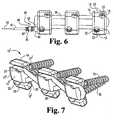
- the strand 38, 39may be threaded through blocks 10 in a figure eight configuration.
- the strand 38may also be threaded through blocks 10 in a straight loop configuration.
- the strand 38 or adjustable spinal tether 40may be threaded through the channels in the blocks 10 in either a figure eight or loop configuration or any combination of both as desired.
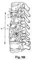
- blocks 10'are shown with like elements labeled as previously.
- Blocks 10'have anterior channel 20' and posterior channel 21'.
- anterior channel 20' and posterior channel 21'extend between upper surface 15' and lower surface 16' as well as up through top surface 11'.
- anterior channel 20' and posterior channel 21'are defined such that the portion nearer to bottom surface 12 is slightly offset from that defined in top surface 11'.
- the channels 20', 21' in blocks 10'permit the synthetic strand 38 to be inserted into blocks 10' through top surface 11'. Since channels 20', 21' have a slightly offset region nearer to the bottom surface 12, when synthetic strand 38 is drawn taut it is secured within the channels and will not slip out through top surface 11'.
- blocks 10are shown attached to vertebral bodies 60 with artificial strand 38 spanning intervertebral discs 61.
- the ends of strand 38are shown tied together in a knot 65.
- knot 65may be tied in an intermediate location between two of the vertebral blocks 11 as opposed to knot 65 as seen in FIG. 8A.
- blocks 10are again shown attached to vertebral bodies 60.
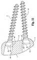
- the intervertebral discs 61are spanned by an artificial strand 39 which is part of adjustable spinal tether 40.
- the crimp 45may be at an intermediate location between blocks.
- the arrow S kparallels the longitudinal axis of the spinal column made up of vertebral bodies and intervertebral discs.
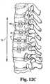
- FIG. 12Aa plurality of spinal staples 100 with legs 102, 103 anchored in adjacent vertebral bodies 60 are shown. Crossbar 101 spans intervertebral disc 61.
- FIG. 12Ban embodiment is shown wherein two staples 200 are anchored in adjacent vertebral bodies 60. In this embodiment, the spinal staples 200 have notches 221 on the back of the staple for final seating of the staple into bone. This allows the surgeon to drive in each tine independently as necessary.
- FIG. 12Ca plurality of spinal staples 400 are anchored adjacent vertebral body 60. In this embodiment, each spinal staple 400 has four prongs. It should be understood that in each of the embodiments of FIGS. 12A-C the spinal staples may include notches on the back of the staple as desired. It should be further understood that any of the embodiments disclosed may entail the use of one, two, or even more than two spinal staples at each level.
- Vertebral interbody staple 200is generally u-shaped with cross bar 201 between legs 202 and 203.
- Staple 200has inner surface 210 and outer surface 220.
- Leg 202has a pointed tip 204 and leg 203 has a pointed tip 205 for insertion into the vertebral bodies.
- tips 204, 205may have a variety of configurations.
- the legs or tines in all of the embodiments in FIGS. 13-15may have barbs on the inner surface or outer surface as desired.
- 13-15may be used in the previously described method of vertebral body tethering without fusion.
- the back of staple 200has a plurality of notches 221 for final seating of the staple into the bone or vertebrae. Notches 221 aid the surgeon in driving in each tine or leg 202, 203 independently as necessary (see FIG. 12B).
- Spinal staple 200has a center line 215 around which it is symmetrical. An angle 225 subtended by axis 215 and a line extending from the tip 205 of leg 203 preferably defines an angle of 37 degrees. Similarly, the angle 226 from between the inner surface 210 and outer surface 220 of leg 202 is preferably 27 degrees.
- the width 230 of the staple 200 between tip 204 and tip 205is preferably 9.5mm and the greatest width 227 of staple 200 is preferably 19.5mm.
- the height 232 of the notches 221 as illustratedis on the order of 0.5mm and similarly the thickness 231 of crossbar 201 and a notch 221 is preferably approximately 2.25mm.
- the height 229 of spinal staple 200is preferably on the order of 16mm.
- the distance 233 between adjacent notches 221is approximately 1.5mm.
- Vertebral interbody staple 300is generally u-shaped with cross bar 301 between legs 302 and 303.
- Staple 300has inner surface 310 and outer surface 320.
- Leg 302has a pointed tip 304 and leg 303 has a pointed tip 305 for insertion into the vertebral bodies. It should be understood that tips 304, 305 may have a variety of configurations.
- the back of staple 300has a plurality of notches 321 for final seating of the staple into the bone or vertebrae. Notches 321 aid the surgeon in driving in each tine or leg 302, 303 independently as necessary.
- Spinal staple 300has a center line 315 around which it is symmetrical. An angle 325 subtended by axis 315 and a line extending from the tip 305 of leg 303 preferably defines an angle of 50 degrees. Similarly, the angle 326 is preferably 50 degrees.
- the width 330 of the staple 300 between tip 304 and tip 305is preferably 9.5mm and the greatest width 327 of staple 300 is preferably 17.18mm.
- the height 329 of spinal staple 300is preferably on the order of 10mm.
- the distance 333 between adjacent notches 321is approximately 2mm.
- Shape-memory alloy staple 400has four prongs or tines 402, 404, 406, 408 with pointed tips 403, 405, 407, and 409 respectively.
- the legs 402, 404, 406, 408are interconnected by a cross plate 401.
- the staple 400is symmetrical about the imaginary axis 415 which bisects the width of the staple 400.
- Crossbar or cross plate 401has a bore 450 defined therein extending between outer surface 420 and inner surface 410.
- the bore 450is defined by a tapered insertion surface 460 adjoining a surface 461 generally parallel to the axis 415. Bore 450 is intended to receive a fastener such as a screw or a bolt. This fastener may be attached to other fasteners received in the bores of other staples by an artificial strand or adjustable tether such as those previously described in the application entitled "Adjustable Spinal Tether.”
- the greatest width 427 of staple 400is on the order of 19.5mm.
- the lesser width 430 separating pointed tips 403 and 407 or 405 and 409 respectivelyis on the order of 9.5mm.
- Preferably bore 450has a circular cross section defined by surface 461 having a diameter on the order of 6.5 mm.
- the thickness 431 of crossbar or cross plate 401is on the order of 2.25mm.
- the width 428 of crossbar or cross plate 401is on the order of 10mm.
- the height 429b defined between the pointed tips of the legs of the staple 400 and the arch formed between adjacent legs 402 and 404 or 406 and 408 respectivelyis approximately 12mm.
- the total height 429a from the pointed tips to the top most portion of the back of the staple as defined by cross plate 401is approximately 16mm.
- the height 462 of tapered insertion surface 460 along axis 415 parallel to the axis 415is approximately 1 mm.
- the width 470 of the arch formed between adjacent legs 406 and 408 or 402 and 404 respectivelyis approximately 6mm.
- the angles 426 subtended by each tip 403, 405, 407, and 409 between inner surface 410 and outer surface 420is approximately 27 degrees.
- the angle 425 subtended between axis 415 and a line tangential to the outer surface 420 at any of the tipsis approximately 37 degrees.
- the deformed martensitic insertion shape of the legs of the staplesis shown in phantom. It should be understood that this deformed state may arise from the formation of martensite because of temperature conditions or the formation of stress induced martensite from the application of a force. After the various embodiments of the staples are inserted in their open position, either the stress is released or the staple is heated to reform the staple to its closed memorized shape.
- Each block 510has a top surface 511, a bottom surface 512, intermediate surfaces 551, 552, and first and second sets of opposing side surfaces.
- the block 510is oriented so that the first set of side surfaces 513a, 513b, and 514a, 514b are located on an anterior and a posterior part respectively of the spine (similar to side surfaces 13 and 14 in FIGS. 8 and 9).
- the first set of side surfacesincludes an upper anterior side surface 513a and a lower anterior side surface 513b and an upper posterior side surface 514a and lower posterior side surface 514b.
- the block 510has a generally curved shape in a transverse direction from the lower anterior surface 513b to the lower posterior surface 514b corresponding to the antero-lateral anatomy of vertebral bodies.
- the bottom surface 512is preferably (but not necessarily) configured to contact the vertebral body.
- Each block 510has a second set of side surfaces 515, 516 which are oriented to face substantially upward and downward along the longitudinal axis of the spine, similar to side surfaces 15, 16 in FIGS. 8 and 9.
- the upper surface 515 and lower surface 516 of each block 510define at least one opening or channel for receiving a synthetic strand or adjustable spinal tether.
- the channelmust either have a post or divider somewhere along its length around which the strand or adjustable spinal tether is wrapped or, alternatively, the strand or adjustable spinal tether may be threaded through the channel and around either the top surface 511 or bottom surface 512 of each block 510.
- each block 510has two substantially parallel channels, an anterior channel 520 and a posterior channel 521.
- Anterior channel 520 and posterior channel 521extend in a direction along a line connecting upper surface 515 and lower surface 516. It is contemplated that anterior channel 520 and posterior channel 521 may extend in different directions and/or be curved in between upper surface 515 and lower surface 516. It is further contemplated that anterior channel 520 and posterior channel 521 may be at an angle with respect to either or both of upper surface 515 and lower surface 516. Moreover, channels 520 and 521 may both be closer to anterior surface 513 than posterior surface 514 or vice versa.
- channels such as 520 and 521may instead connect the first set of opposing upper side surfaces 513a and 514a or may connect some combination of the first and second sets of opposing side surfaces.
- each block 510further defines at least one bore extending between top surface 511 and bottom surface 512.
- Each block 510may have one or more bores for receiving a fastener or connect each block to a vertebral body.
- block 510has two bores, an anterior bore 522 and a posterior bore 523. It should be understood that each block 510 may have only one bore or more than two depending on the number of fasteners a surgeon wishes to use to attach each block to a vertebral body.
- Each bore 522, 523extends between the top surface 511 and bottom surface 512 of block 510. Bores 522, 523 are defined in block 510 with dimensions such that each bore may receive one of the fasteners used to attach the block 510 to the vertebral body.
- the bores of this embodiment of the anterior blockmay include features similar to those described in the previous embodiment and shown in FIGS. 10 and 11.
- the boresmay have tapered surfaces for facilitating insertion of fasteners, may be shaped for a ball and socket interconnection, may have matching threading on the head of a fastener to prevent screw back out and the bores may be arranged in a variety of angles with respect to each other.
- length 530is 6mm
- length 531is 6.7mm
- length 532is 2.33mm
- angle 533is 30 degrees
- angle 534is 20 degrees.
- length 535is 17.82mm
- length 536is 19.16mm
- length 537is 26.39mm
- angles 538a and 538bare both preferably 20 degrees.
- length 539is 15mm
- length 540is 7.5mm
- length 541is 15mm.
- length 542is 10.5mm, 543 is 4.5mm.
- length 544is 10.6mm
- length 545which defines the diameter of bore 523 at one point is 6.4mm
- length 546is 20
- length 547which defines the diameter of the bore at one point, is 6mm
- length 548which defines the minimum diameter of the bore is 5.05mm
- angle 549is five degrees.
- length 560is 8.4mm
- length 563is 7mm
- angle 564is 15 degrees and angle 565 is 10 degrees.
- length 570is 3.1 mm
- length 571is 7mm
- length 572is 12mm
- angle 573is 10 degrees.
- length 574is 4.53mm
- length 575is 1 mm
- length 576is 16.85mm
- length 577is 11.35mm
- length 578is 7.5mm
- length 579is 3.53mm
- length 580is 2mm
- length 581is 11.85mm
- length 582is 17.35mm
- angles 583 and 584are both 20 degrees.
- this embodiment of a blockmay be used in various manners similar or identical to those shown in FIGS. 3-9 with an artificial strand or adjustable tether.
- the advantages of this embodimentinclude the reduction in the amount of volume and the amount of metal. By essentially removing portions of what was a previously rectangular cross section, this embodiment of the block has a lower profile and is less bulky.
Landscapes
- Health & Medical Sciences (AREA)
- Orthopedic Medicine & Surgery (AREA)
- Life Sciences & Earth Sciences (AREA)
- Engineering & Computer Science (AREA)
- Biomedical Technology (AREA)
- Neurology (AREA)
- Surgery (AREA)
- General Health & Medical Sciences (AREA)
- Veterinary Medicine (AREA)
- Heart & Thoracic Surgery (AREA)
- Public Health (AREA)
- Animal Behavior & Ethology (AREA)
- Molecular Biology (AREA)
- Medical Informatics (AREA)
- Nuclear Medicine, Radiotherapy & Molecular Imaging (AREA)
- Rheumatology (AREA)
- Cardiology (AREA)
- Oral & Maxillofacial Surgery (AREA)
- Transplantation (AREA)
- Vascular Medicine (AREA)
- Prostheses (AREA)
- Surgical Instruments (AREA)
Description
- Current operative methods for treating spinal deformities, particularlyscoliosis, include correction of the curve by some internal fixation device,and fusion of the spine in the corrected state usually accomplished by theplacement of bone graft between vertebrae. This is usually accomplishedwith posterior surgery, although anterior procedures are becoming morepopular, as well as combinations of anterior and posterior procedures.Several instrumentation systems are available from various manufacturersto correct and stabilize the spine while fusion occurs. Among them areTSRH®, CD™, CD Hopf™, CD Horizon™, ISOLA™, Moss Miami andSynthes Universal Spine Systems. Nonoperative methods do exist and areused when applicable. These nonoperative methods include bracing andobservation.
- Juvenile idiopathic scoliosis occurs between the ages of 4 and 10years. It can resolve spontaneously, respond to nonoperative therapy, orprogress until fusion is required. Stapling across long bone physes haslong been recognized as a predictable method of treating limbmalalignment. Vertebral interbody stapling across the cartilaginousendplates and discs was attempted by Nachlas and Borden in a caninescoliosis model. Early human results in the 1950s were disappointing. Roaf reported limited successful correction of scoliosis by uninstrumentedconvex hemiepiphysiodesis. His study did not have a uniform patientpopulation by skeletal maturity or scoliosis etiology.
- Further shortcomings of current operative methods and devices arenumerous. Patients with juvenile scoliosis who undergo curve stabilizationwith subcutaneous rods would be subject to multiple surgical proceduresfor lengthening as they grow. Anterior and/or posterior spinal fusion in theskeletally immature patient often results in loss of vertebral body height andgirth. Additionally, poor self-image may occur in adolescent patients whoare braced for scoliosis. Moreover, curve stabilization with bracing is onlysuccessful in approximately 75% of patients. Another problem is that somechildren, while not currently candidates for a definitive fusion procedure,are likely to need such a procedure in the future. These would includechildren less than ten years of age, small in stature, premenstrual or risertwo or lower, and those not physically able to tolerate the surgery requiredfor a definitive fusion procedure. It would be preferable to eliminate theneed for that procedure altogether.
- According to the present invention there is provided a device for treatingabnormal alignment of a spine, the spine having a convex side and a concave side, thedevice being adapted to constrain spinal curve progression across a plurality ofvertebrae levels and comprising: a plurality of staples each of said staples having abridge and at least two prongs extending therefrom, at least one of said prongs beingadapted to be anchored to a first vertebral body on the convex side of the spine, atleast one of said prongs being adapted to be anchored to a second vertebral body onthe convex side of the spine; and said plurality of staples are formed of a shapememory alloy; said bridge of each of said plurality of staples beingsized to extend across a single intervertebral disc space, the shape memory alloyexhibits superelastic characteristics at about body temperature and the plurality ofstaples are each structurally configured so as to exhibit sufficient flexibility to flexiblyconstrain curve progression across a plurality of vertebrae levels along at least aportion of the convex side of the spine to treat the abnormal alignment without fusion.
- WO-A-98/17189 discloses a device for securing at least twovertebrae by fusion. The device comprises a bridge andat least two prongs and it is made of a shape memoryalloy. The known device does not exhibit sufficientflexibility to flexibly constrain curve progression acrossa plurality of vertebrae levels and thus it is notadapted to treat abnormal spine alignment withoutfusion.
- FIG. 1 is a perspective view of an embodiment of a spinal staple inaccordance with this invention.
- FIG. 2 is a side view of the spinal staple of FIG. 1.
- FIG. 3 is a perspective view of an embodiment of a tether not according to thepresent invention including a set of blocks and fasteners with a strandthreaded through channels in the blocks.
- FIG. 4 is a side view of the embodiment of FIG. 3.
- FIG. 5 is a top view of an alternative to the embodiment of FIG. 3where the strand is an adjustable spinal tether in a figure eightconfiguration.
- FIG. 6 is a top view of an alternative to the embodiment of FIG. 5with the tether in a straight loop configuration.
- FIG. 7 is a perspective view of another embodiment in which thechannels open through the top surface of the blocks.
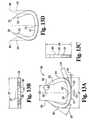
- FIG. 8A is a schematic illustration of the embodiment of FIG. 3attached to vertebral bodies on the convex side of a child's scoliotic spine.
- FIG. 8B is a schematic illustration of an alternative embodiment ofFIG. 8A where the strand is knotted in between the blocks.
- FIG. 9A is a schematic illustration of the embodiment of FIG. 5attached to vertebral bodies on the convex side of a spine.
- FIG. 9B is a schematic illustration of an alternative embodiment ofFIG. 9A where the adjustable strand is crimped in between the blocks.
- FIG. 10A is a cross-sectional view of one embodiment of theinterconnection between the fasteners and the blocks.
- FIG. 10B is a cross-sectional view of another embodiment of theinterconnection between the fasteners and the blocks having a screw backoutmechanism.
- FIG. 11 is a cross-sectional view of another embodiment of theinterconnection between the fasteners and the blocks.
- FIG. 12A is a schematic illustration of the embodiment of FIG. 1attached to vertebral bodies on the convex side of a spine.
- FIG. 12B is a schematic illustration of the embodiment of FIG. 13 orFIG. 14 attached to vertebral bodies on a convex side of a spine.
- FIG. 12C is a schematic illustration of the embodiment of FIG. 15attached to vertebral bodies on the convex side of the spine.
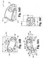
- FIG. 13A is a side view of another embodiment of a spinal staple.
- FIG. 13B is a top view of the spinal staple of FIG. 13A
- FIG. 13C is a side view of FIG. 13A.
- FIG. 13D is a side view of the spinal staple of FIG. 13A with theinsertion position shown in phantom.
- FIG. 14A is a side view of another embodiment of a spinal staple.
- FIG. 14B is a top view of the embodiment of FIG. 14A.
- FIG. 14C is a side view of the embodiment of FIG. 14A.
- FIG. 14D is a perspective view of the embodiment of the spinalstaple of FIG. 14A.
- FIG. 14E is a side view of the embodiment of the spinal staple ofFIG. 14A showing the tines in the insertion position in phantom.
- FIG. 15A is a side view of another embodiment of a spinal staple ofthe present invention.
- FIG. 15B is a top view of the embodiment of FIG. 15A.
- FIG. 15C is another side view of the embodiment of the spinal stapleof FIG. 15A.
- FIG. 15D is a perspective view of the embodiment of FIG. 15A.
- FIG. 15E is a side view of the embodiment of the spinal staple of
- FIG. 15A showing the times in the insertion position in phantom.
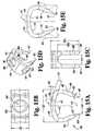
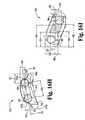
- FIG. 16A is a side view of a block.
- FIG. 16B is a top view of the block of FIG. 16A.
- FIG. 16C is another side view of the block in FIG.16A.
- FIG. 16D is a perspective view of the block ofFIG. 16A.
- FIG. 16E is another top view of FIG. 16A illustrating further detail ofthe block.
- FIG. 16F is a cross-sectional view along the
line 16F in FIG. 16E. - FIG. 16G is another cross-sectional view of FIG. 16E along the
line 16G. - FIG. 16H is another side view of the embodiment of FIG. 16Aillustrating further detail.
- FIG. 16I is a cross-sectional view of FIG. 16H along the lines 16I.
- For the purposes of promoting an understanding of the principles ofthe invention, reference will now be made to the embodiment illustrated inthe drawings and specific language will be used to describe the same. Itwill nevertheless be understood that no limitation of the scope of theinvention is thereby intended, such alterations and further modifications inthe illustrated device, and such further applications of the principles of theinvention as illustrated therein being contemplated as would normally occurto one skilled in the art to which the invention relates.
- Various devices and surgical approaches are possible to implementthe underlying idea of this invention. That idea is the correction of spinaldeformities, particularly scoliosis, through fusionless tethering. Thecorrection of the deformity is achieved by attaching a tether to the vertebralbodies on the convex side of the spine. This tether will minimize or arrestgrowth on the convex or "long" side of the spine and allow the concave or"short" side of the spine to grow and catch up with the long side.Altematively, fusionless tethering may treat abnormal spinal alignment bysimply preventing further misalignment such as curve progression.
- A wide variety of surgical approaches may be used in implementingtethering of the convex side. One approach is an open thoracotomy(standard). Another surgical approach contemplated is a minimallyinvasive thoracoscopic approach (endoscopic). The surgical approach mayalso be a combined anterior/posterior approach (standard or endoscopic).It should be understood that the invention can be practiced using othersurgical approaches known to persons of ordinary skill in the art.
- The longitudinal element is a spinal staple formed in a varietyof shapes and sizes depending on its application. Staples may act aseither the longitudinal element, the anchor, or both.The staples aremanufactured out of shape memory materials or alloys such as nickeltitanium to enhance fixation. One example of such an alloy is Nitinol soldby Memry Corporation of Menlo Park, Califomia. Further details ofpreferred use, size, and material selection for the spinal staple may befound in copending patent application USSN 09/421,903, entitled "ShapeMemory Alloy Staple" filed on October 20, 1999 and commonly assigned tothe assignee of the present application.
- The above disclosure deals specifically with the broad range ofdevice concepts envisioned for fusionless tethering of deformities in orderto achieve permanent correction. The specifics with regard to the methodare similarly broad. A wide range of spinal deformities could be managed.The primary indications will be progressive idiopathic scoliosis with orwithout sagittal deformity in either infantile or juvenile patients. Thepreferred patient population upon which to practice the present invention isprepubescent children (before growth spurt) less than ten years old. Otherpatient groups upon which the present invention may be practiced includeadolescents from 10-12 years old with continued growth potential. It shouldbe understood that fusionless tethering may be used on older childrenwhose growth spurt is late or who otherwise retain growth potential. Itshould be further understood that fusionless tethering may also find use inpreventing or minimizing curve progression in individuals of various ages.
- Generally, in the case of scoliosis, tethering will take place on theconvex side of the curve. An anterior, minimally invasive (thoracoscopic)procedure can be carried out on the convex side of the spinal curve in order to prevent continued growth on that side of the curve. As the pre-growthspurt child approaches puberty, the untethered side of the spine willgrow unconstrained, ultimately eliminating the curvature of the spine in thefrontal plane. It is preferable to deliver this method of treatment in aminimally invasive approach using thoracoscopic instrumentation. It iscontemplated as within the scope of the invention, however, that open useof these systems may be appropriate in some cases. It is furthercontemplated as within the scope of the invention that the procedure maybe posterior as well as anterior, or some combination of both. Finally, itshould be understood that if the procedure fails to correct the curve butdoes, in fact, prevent further progression (which includes increase in themagnitude of the curve) it can and should be considered successful.EXAMPLE ONE: Thoracoscopic Assisted Spine Stapling.
- In one embodiment of the invention, fusionless correction ofscoliosis is achieved by thoracoscopically placing shape memory alloystaples into the vertebral bodies on the convex side of the spine. Thestaples will span the intervertebral space and act as a tether on the spine.This tether will arrest growth on the convex ("long") side of the spine andallow the concave ("short") side of the spine to grow and catch up with thelong side. Once correction is achieved, the staple may then be removedthoracoscopically if desired. The removal of the staples permits furthergrowth of the vertebral bodies. It should be understood that the methoddescribed is equally applicable in non-endoscopic procedures. It should befurther understood that the staples used may be made of a conventionalimplant metal such as titanium or stainless steel instead of a SMA.
- The following contraindications for use of thoracoscopically assistedspinal stapling should be noted: (1) Inability to wear an orthosispostoperatively, (2) Greater than 40 degree kyphosis, (3) Medicalcontraindication to general anesthetic, (4) Pulmonary function which wouldcontraindicate intraoperative collapse of the convex lung, and (5) Scoliosisdeformity where three or more disc spaces are not accessible to thoracoscopically assisted vertebral interbody stapling. It should beunderstood, however, that the presence of any or all of the abovementioned contraindications does not preclude the potential utility of spinalstapling and/or vertebral body tethering.
- The general details of one embodiment of the surgical techniquewould be as follows. General anesthesia is utilized. A double lumenendotracheal tube is inserted, with possible assistance of fiberopticvisualization. The convex lung is collapsed. A general or vascular surgeonfamiliar with endoscopic surgery in the thorax may be used as an assistant.The patient is positioned in the lateral decubitus position with the convexside of the scoliosis in the up position. The table is not flexed. Fivevertebrae (four intervertebral discs) are usually stapled. The apicalvertebral body, the two vertebrae proximal, and the two vertebrae distal aretreated. Three endoscopic ports are utilized. The first port is anterior andpositioned over the apex of the scoliosis. The second and third ports aremade in the posterior auxiliary line with the second port being centeredover the second vertebrae of the five being treated and the third port beingcentered over the fourth vertebrae being treated. The endoscope ismaintained in the first port and a fan retractor is placed in the second port.An anterior-posterior (AP) radiograph is used to confirm the levels. Theparietal pleura is not excised and the segmental vessels are avoided.
- A number of general surgical instruments are used in the procedurealong with the following system specific implants and instruments. Themain implant is of course a spinal staple, preferably manufactured from ashape memory material. The size will vary depending on the size andnumber of the vertebral bodies to be spanned. The instruments used in theprocedure may also include: Staple Awl, Staple Opener, Straight StapleInserter, Angled Staple Inserter, Staple Impactor, Staple Extractor.
- Pilot holes are made using the Staple Awl. The pilot holes are madeanterior to the midbody of the vertebrae. The Staple Awl is inserted partway and position is checked with either x-ray or image intensifier. Prior to removal of the Staple Awl from the pilot holes, an electric cauterizer (Bovie)can be placed in contact with the endcap of the Staple Awl to minimizebleeding from the pilot holes. In one preferred embodiment, two sets of pilotholes are made at each level to accommodate two staples per disc space.Two staples are then placed spanning each disc space. The first staple isloaded into either the Straight Staple Inserter or the Angled Staple Inserter.The staple is then placed into the pilot holes previously made with theStaple Awl. The Inserter may be tapped with a mallet to facilitateplacement of the staple. The staple is then released from the Inserter andthen the instrument is removed. If further seating of the staple is required,the Staple Impactor may be used in conjunction with a mallet for finalseating of the staple into the bone. The aforementioned steps are repeatedfor the next staple at that spinal level. It should be understood, however,that tethering may also be accomplished with just one staple instead of twospanning each disc space. It should be further understood that the use ofmore than one staple allows for correction of spinal curvature in more thanone plane.
- The instruments in the second and third ports are switched and theremaining two discs are stapled. The wounds are closed and a ten ortwelve gauge chest tube is inserted which is withdrawn at twenty-four hourspostop. The chest tube is used to prevent pneumothorax since there is nohemothorax. Once the endoscope is in place, the remainder of theprocedure seldom takes more than one hour. Hospitalization is usually fortwo to three days.
- Apical vertebral interbody stapling theoretically affords immediateand reversible fixation of the anterior vertebral physes. Thoracoscopicinsertion minimizes damage to surrounding tissues and permits placementof multiple staples to allow curve correction in more than one plane.
- With reference to FIGS. 1 and 2, one embodiment of an
vertebralinterbody staple 100 that may be used in the above described method isshown.Staple 100 is generally U-shaped withcrossbar 101 betweenlegs Staple 100 hasinner surface 110 andouter surface 120.Leg 102 has a pointedtip 104 andleg 103 has a pointedtip 105 forinsertion into the vertebral bodies. It should be understood thattips Leg 102 hasbarbs 106 oninnersurface 110 andbarbs 107 onouter surface 120. Similarly,leg 103 hasbarbs 108 oninner surface 110 andbarbs 109 onouter surface 120.Barbs inner surface 110 andouter surface 120 of eachleg staple 100 allows the use of shorter barbs in the direction transverseto the longitudinal axis of each leg. It should be understood, however, thateachleg inner surface 110 oroutersurface 120. - It should be noted that in one
preferred embodiment crossbar 101,andlegs elliptical crossbar 101 is helpful in controlling rotation of thestaple 100 andpermits some assistance in staple removal. It should be understood thatthe profile oflegs crossbar 101 may be other than elliptical,such as a circular cross-section. It should be further understood thatlegs portion 101 may have different profiles. Thestaple design of FIGS. 1 and 2 is made ofa SMA. - While details of several embodiments of the staple are discussed inthe copending application titled "Shape Memory Alloy Staple," somegeneral points are reviewed here for convenience. The staples arepreferably made of nitinol, a biocompatible, shape memory metal alloy oftitanium and nickel. Staples are capable of being bent when cooled andreform to their original shape when reheated. It is also possible to takeadvantage of the shape memory alloy's ability to transform from itsaustentic state to a stress induced martensitic state. The metal changesshape with temperature or under the influence of stress because of crystalline phase changes. Thus a staple made of a SMA can be insertedin two different ways as desired. In one embodiment the SMA staple iscooled and then deformed while at a temperature less than thetransformation temperature at which it is in the martensitic phase. Thestaple is then inserted in its deformed shape and when heated will reformto its original shape. In a second embodiment the staple is deformed andinserted while held in the deformed state. In the second embodiment theSMA is selected to have a temperature transformation range such that thestaple undergoes a transition from austenite to stress-induced martensiteunder the influence of the deformation forces. Thus, when the staple of thesecond embodiment is inserted and released it is already at a temperaturesuch that it automatically attempts to reform to its original shape.
- The metal's properties at the higher temperature (austenite phase)are similar to those of titanium. The temperature at which the staples willundergo the shape transformation can be controlled by the manufacturingprocess and the selection of the appropriate alloy composition. Injury tothe surrounding tissues should be negligible if the transformationtemperature is near body temperature. There is no threat of thermal injuryto the spinal cord or nerves, or adjacent vascular structures. Nitinol has avery low corrosion rate and has been used in a variety of medical implants(i.e., orthodontic appliances, stents). Implant studies in animals haveshown minimal elevations of nickel in the tissues in contact with the metal;the levels of titanium are comparable to the lowest levels found in tissuesnear titanium hip prostheses.
- Another device not representing the invention but useful for correction of spinal deformities throughfusionless tethering involves the use of blocks similar or identical to thosedisclosed in the above mentioned U.S. Patent No. 5,702,395 to Hopf titled"Spine Osteosynthesis Instrumentation for an Anterior Approach" alongwith cabling or artificial strands. Several preferred embodiments for use as an artificial strand are disclosed in the above mentioned provisional
patentapplication USSN 60/130,910 entitled "Adjustable Spinal Tether." - With reference to FIGS. 3 and 4, one embodiment includes a set ofthree blocks with corresponding fasteners and a synthetic strand or cablethreaded through channels in the blocks is shown. It should be understoodthat anywhere from two to greater than five blocks may be used. In onepreferred embodiment the number of blocks is three. Each
block 10 has atop surface 11 and abottom surface 12 along with first and second sets ofopposing side surfaces. Theblock 10 is oriented so that in the first set,side surfaces 13, 14 are located on an anterior and a posterior partrespectively of the spine (see also FIGS. 8 and 9). Theblock 10 has agenerally curved shape in a transverse direction from theanterior surface 13 to theposterior surface 14 corresponding to the antero-lateral anatomyof vertebral bodies. Thebottom surface 12 is configured to contact avertebral body. - Each
block 10 has a second set of side surfaces 15, 16 which areoriented substantially upward and downward along the longitudinal axis Skof the spine (see FIGS. 8 and 9). Theupper surface 15 andlower surface 16 of eachblock 10 define at least one opening or channel for receivingsynthetic strand 38. In an embodiment with only one channel, the channelmust either have a post or divider somewhere along its length aroundwhich thestrand 38 is wrapped or else thestrand 38 may be threadedthrough the channel and around either thetop surface 11 orbottom surface 12 of eachblock 10. In one preferred embodiment (see FIG. 3), eachblock 10 has two substantially parallel channels, ananterior channel 20 and aposterior channel 21.Anterior channel 20 andposterior channel 21 extendin a direction along a line connectingupper surface 15 andlower surface 16. It is contemplated thatanteriorchannel 20 andposterior channel 21 may extend in different directionsand/or be curved in betweenupper surface 15 andlower surface 16. It isfurther contemplated thatanterior channel 20 andposterior channel 21 may be at an angle with respect toeither or both ofupper surface 15 andlower surface 16. Moreover,channels anterior surface 13 thanposterior surface 14 or vice versa. Selection of various channelorientations permits configurations for the synthetic strand other than thefigure eight or straight loop configuration discussed below. Also, it shouldbe understood that the channels such as 20 and 21 may instead connectthe first set of opposing side surfaces 13 and 14 or may connect somecombination of the first and second sets of opposing side surfaces. - Additionally, each
block 10 further defines at least one boreextending betweentop surface 11 andbottom surface 12. Eachblock 10may have one or more bores for receiving a fastener to connect each blockto a vertebral body. In onepreferred embodiment block 10 has two bores,ananterior bore 22 and aposterior bore 23. It should be understood thateachblock 10 may have only one bore or more than two depending on thenumber of fasteners a surgeon wishes to use to attach each block to avertebral body. Each bore 22, 23 extends between thetop surface 11 andbottom surface 12 ofblock 10.Bores block 10 withdimensions such that each bore may receive one of the fasteners used toattach theblock 10 to the vertebral body. - The bottom portion of
bores bottom surface 12 arepreferably sized to snugly receive theheads fasteners top portion 22a andbottom portion 22b. Similarly bore 23 has atop portion 23a and abottom portion 23b.Top portions fasteners bores head 32 offastener 30 has atop portion 32a with a notch therein forreceiving a driving mechanism and abottom portion 32b configured toengage thebottom portion 22b ofbore 22. Similarly, thehead 33 offastener 31 has atop portion 33a with a notch therein for receiving a driving mechanism and abottom portion 33b configured to engage thebottomportion 23b ofbore 23. - With reference to FIG. 10B, an alternative embodiment is shownwith a mechanism to aid in the prevention of screw back out. Withreference to FIG. 10B, in which like elements are labeled as previously, it isseen that bore 122 has a top portion 122a and
bottom portion 122b.Similarly, bore 123 has atop portion 123a and abottom portion 123b.Topportions 122a and 123a are preferably (but not necessarily) tapered forfacilitating insertion offasteners bores head 132 offastener 130 has atop portion 132a with anotch therein for receiving a driving mechanism and abottom portion 132bconfigured to engage thebottom portion 122b ofbore 122. Similarly, thehead 133 offastener 131 has atop portion 133a with a notch therein forreceiving a driving mechanism and abottom portion 133b configured toengage thebottom portion 123b ofbore 123. Thehead 132 offastener 130 hasexternal threading 132c defined thereon which engages threading122c defined inbore 122 and aids in the prevention of screw back out.Similarly, thehead 133 offastener 131 has threading 133c defined on thehead 133 which engages threading 123c defined inbore 123. - It should be understood that bores 22, 23 may also be sized toloosely receive
heads bores fasteners block 10. With reference to FIG. 11 in which likeelements are labeled as previously, thebottom portions 32b', 33b' ofheads bottom portions 22b', 23b'. Again thetop portions bores fasteners block 10 is substantially fixed. It should be understood that in either case, it may be desirable in some situations to use a screw back out system asdescribed with reference to FIG. 10B or others known in the art. - In one embodiment, bore 22 intersects with
channel 20 and bore 23intersectschannel 21. It should be understood, however, that thebores channels bores channels heads fasteners channels fasteners bores 22, 23 (see FIGS. 5, 8, and 9). As a result, strand orcable 38 isunobstructed when threaded throughchannels - With reference to FIG. 3, the
artificial strand 38 may be a strand withtwo ends tied or spliced together (see FIGS. 8A and 8B). Theartificialstrand 38 may be made of any suitable biocompatible material such asstainless steel or titanium or a polymer such as polyester or polyethylene.With reference to FIG. 5, another embodiment has adjustablespinal tether 40 threaded through thechannels blocks 10. Adjustablespinaltether 40 has a strand orcable portion 39 having afirst end 41 and asecond end 42. First end 41 ends in aleader 43 for ease of threadingadjustablespinal tether 40 through thechannels blocks 10. Theleader 43 may be an extrusion offirst end 41 or may be otherwise affixedontofirst end 41 by press fitting, adhesive, or other means known in the art.Details of various embodiments of the adjustable spinal tether constructionmay be found in the above mentioned patent application titled "AdjustableSpinal Tether." Second end 42 may be wrapped around or otherwise attached to agrommet 44. In an alternative embodiment the adjustable spinal tethermay havesecond end 42 looped around on itself to form an eyelet (notshown) without the need for a grommet. Theleader 43 andfirst end 41 arethreaded throughgrommet 44 and crimp 45 attached to thegrommet 44.Crimp 45 has external threading 47 matching internal threading (notshown) onlock nut 46.Lock nut 46 is tightened down oncrimp 45 to securecrimp 45 on strand orcable 39 when the appropriate length isthreaded through thechannels blocks 10 and drawn taut. Theexcess length ofstrand 39 may then be trimmed off abovecrimp 45. Withreference to FIGS. 3, 5 it is seen that thestrand blocks 10 in a figure eight configuration. With reference to FIG. 6,in an alternative embodiment it is seen that thestrand 38 may also bethreaded throughblocks 10 in a straight loop configuration. It should beunderstood that for all embodiments thestrand 38 or adjustablespinaltether 40 may be threaded through the channels in theblocks 10 in either afigure eight or loop configuration or any combination of both as desired.- With reference to FIG. 7, in yet another embodiment blocks 10' areshown with like elements labeled as previously. Blocks 10' have anteriorchannel 20' and posterior channel 21'. In this embodiment anterior channel20' and posterior channel 21' extend between upper surface 15' and lowersurface 16' as well as up through top surface 11'. Additionally, anteriorchannel 20' and posterior channel 21' are defined such that the portionnearer to
bottom surface 12 is slightly offset from that defined in top surface11'. The channels 20', 21' in blocks 10' permit thesynthetic strand 38 to beinserted into blocks 10' through top surface 11'. Since channels 20', 21'have a slightly offset region nearer to thebottom surface 12, whensynthetic strand 38 is drawn taut it is secured within the channels and willnot slip out through top surface 11'. - With reference to FIG. 8A, blocks 10 are shown attached to
vertebralbodies 60 withartificial strand 38 spanningintervertebral discs 61. Theends ofstrand 38 are shown tied together in aknot 65. It should beunderstood that a variety of knots may be used in place ofknot 65. Forexample, with reference to FIG. 8B, in which like elements labeled aspreviously, the knot 65a may be tied in an intermediate location betweentwo of the vertebral blocks 11 as opposed toknot 65 as seen in FIG. 8A. - With reference to FIG. 9A, blocks 10 are again shown attached to
vertebral bodies 60. In this embodiment theintervertebral discs 61 are spanned by anartificial strand 39 which is part of adjustablespinal tether 40. With reference to FIG. 9B, as in the embodiment disclosed in FIG. 8,thecrimp 45 may be at an intermediate location between blocks. Withreference to FIGS. 8A, 8B, 9A, and 9B, it should be noted that the arrow Skparallels the longitudinal axis of the spinal column made up of vertebralbodies and intervertebral discs. - With reference to FIG. 12A, a plurality of
spinal staples 100 withlegs vertebral bodies 60 are shown.Crossbar 101 spansintervertebral disc 61. With reference to FIG. 12B, anembodiment is shown wherein twostaples 200 are anchored in adjacentvertebral bodies 60. In this embodiment, thespinal staples 200 havenotches 221 on the back of the staple for final seating of the staple intobone. This allows the surgeon to drive in each tine independently asnecessary. With reference to FIG. 12C, a plurality ofspinal staples 400 areanchored adjacentvertebral body 60. In this embodiment, eachspinalstaple 400 has four prongs. It should be understood that in each of theembodiments of FIGS. 12A-C the spinal staples may include notches onthe back of the staple as desired. It should be further understood that anyof the embodiments disclosed may entail the use of one, two, or even morethan two spinal staples at each level. - With reference to FIGS. 13A-D, another embodiment of a
spinalstaple 200, such as that used in FIG. 12B is shown.Vertebral interbodystaple 200 is generally u-shaped withcross bar 201 betweenlegs Staple 200 hasinner surface 210 andouter surface 220.Leg 202has a pointedtip 204 andleg 203 has a pointedtip 205 for insertion into thevertebral bodies. It should be understood thattips staple 200 has a plurality ofnotches 221 forfinal seating of the staple into the bone or vertebrae.Notches 221 aid thesurgeon in driving in each tine orleg - To better illustrate the construction of the
staple 200, the dimensionsof one manufactured embodiment are hereafter listed. It should beunderstood, however, that these dimensions are exemplary and notintended to limit the scope of protection sought. The use of dimensionsand tolerances other than those listed are contemplated as within thescope of the invention.Spinal staple 200 has acenter line 215 aroundwhich it is symmetrical. Anangle 225 subtended byaxis 215 and a lineextending from thetip 205 ofleg 203 preferably defines an angle of 37degrees. Similarly, theangle 226 from between theinner surface 210 andouter surface 220 ofleg 202 is preferably 27 degrees. Thewidth 230 of thestaple 200 betweentip 204 andtip 205 is preferably 9.5mm and thegreatest width 227 ofstaple 200 is preferably 19.5mm. Theheight 232 ofthenotches 221 as illustrated is on the order of 0.5mm and similarly thethickness 231 ofcrossbar 201 and anotch 221 is preferably approximately2.25mm. Theheight 229 ofspinal staple 200 is preferably on the order of16mm. Thedistance 233 betweenadjacent notches 221 is approximately1.5mm. As previously mentioned, variations in these design parametersthat would occur to a person of ordinary skill in the art are contemplated aswithin the scope of the invention. - With reference to FIGS. 14A-E, another embodiment of a
spinalstaple 300 is illustrated.Vertebral interbody staple 300 is generally u-shapedwithcross bar 301 betweenlegs Staple 300 hasinner surface 310 andouter surface 320.Leg 302 has a pointedtip 304andleg 303 has a pointedtip 305 for insertion into the vertebral bodies. Itshould be understood thattips staple 300 has a plurality ofnotches 321 for final seating of the staple into the bone or vertebrae.Notches 321 aid thesurgeon in driving in each tine orleg - To better illustrate the construction of the
staple 300, the dimensionsof one manufactured embodiment are hereafter listed. It should beunderstood, however, that these dimensions are exemplary and notintended to limit the scope of protection sought. The use of dimensionsand tolerances other than those listed are contemplated as within thescope of the invention.Spinal staple 300 has acenter line 315 aroundwhich it is symmetrical. Anangle 325 subtended byaxis 315 and a lineextending from thetip 305 ofleg 303 preferably defines an angle of 50degrees. Similarly, theangle 326 is preferably 50 degrees. Thewidth 330of the staple 300 betweentip 304 andtip 305 is preferably 9.5mm and thegreatest width 327 ofstaple 300 is preferably 17.18mm. Theheight 329 ofspinal staple 300 is preferably on the order of 10mm. Thedistance 333betweenadjacent notches 321 is approximately 2mm. As previouslymentioned, variations in these design parameters that would occur to aperson of ordinary skill in the art are contemplated as within the scope ofthe invention. - With reference to FIGS. 15A-E, another embodiment of the shape-memoryalloy staple is shown. The embodiments of the shape-memoryalloy staple shown in FIGS. 13-14 are two pronged, whereas theembodiment shown in FIGS. 15A-E is a four prong staple. Shape-
memoryalloy staple 400 has four prongs ortines pointedtips legs cross plate 401. Thestaple 400 is symmetrical abouttheimaginary axis 415 which bisects the width of thestaple 400. Crossbarorcross plate 401 has abore 450 defined therein extending betweenoutersurface 420 andinner surface 410. Thebore 450 is defined by a taperedinsertion surface 460 adjoining asurface 461 generally parallel to theaxis 415.Bore 450 is intended to receive a fastener such as a screw or a bolt.This fastener may be attached to other fasteners received in the bores of other staples by an artificial strand or adjustable tether such as thosepreviously described in the application entitled "Adjustable Spinal Tether." - To better illustrate the construction of the
staple 400, the dimensionsof one manufactured embodiment are hereafter listed. It should beunderstood, however, that these dimensions are exemplary and notintended to limit the scope of protection sought. The use of dimensionsand tolerances other than those listed are contemplated as within thescope of the invention. - The
greatest width 427 ofstaple 400 is on the order of 19.5mm. Thelesser width 430 separating pointedtips surface 461 having a diameter on the order of 6.5mm. Thethickness 431 of crossbar or crossplate 401 is on the order of2.25mm. Thewidth 428 of crossbar or crossplate 401 is on the order of10mm. Theheight 429b defined between the pointed tips of the legs of thestaple 400 and the arch formed betweenadjacent legs total height 429a fromthe pointed tips to the top most portion of the back of the staple as definedbycross plate 401 is approximately 16mm. Theheight 462 of taperedinsertion surface 460 alongaxis 415 parallel to theaxis 415 isapproximately 1 mm. Thewidth 470 of the arch formed betweenadjacentlegs angles 426 subtended by eachtip innersurface 410 andouter surface 420 is approximately 27 degrees. Similarly,theangle 425 subtended betweenaxis 415 and a line tangential to theouter surface 420 at any of the tips is approximately 37 degrees. Aspreviously mentioned, variations in these design parameters that wouldoccur to a person of ordinary skill in the art are contemplated as within thescope of the invention. - With reference to FIGS. 13D, 14E and 15E, the deformedmartensitic insertion shape of the legs of the staples is shown in phantom. It should be understood that this deformed state may arise from theformation of martensite because of temperature conditions or the formationof stress induced martensite from the application of a force. After thevarious embodiments of the staples are inserted in their open position,either the stress is released or the staple is heated to reform the staple toits closed memorized shape.
- With reference to FIGS. 16A-I, another embodiment of an anteriorblock for spine tethering not representing the invention is shown. Each
block 510 has atop surface 511,abottom surface 512,intermediate surfaces block 510 is oriented so that the firstset ofside surfaces anterior side surface 513a and a loweranterior side surface 513b and anupperposterior side surface 514a and lowerposterior side surface 514b.Theblock 510 has a generally curved shape in a transverse direction fromthe loweranterior surface 513b to thelower posterior surface 514bcorresponding to the antero-lateral anatomy of vertebral bodies. Thebottom surface 512 is preferably (but not necessarily) configured to contactthe vertebral body. - Each
block 510 has a second set of side surfaces 515, 516 whichare oriented to face substantially upward and downward along thelongitudinal axis of the spine, similar to side surfaces 15, 16 in FIGS. 8 and9. The upper surface 515 andlower surface 516 of eachblock 510 defineat least one opening or channel for receiving a synthetic strand oradjustable spinal tether. In an embodiment with only one channel, thechannel must either have a post or divider somewhere along its lengtharound which the strand or adjustable spinal tether is wrapped or,alternatively, the strand or adjustable spinal tether may be threadedthrough the channel and around either thetop surface 511 orbottomsurface 512 of eachblock 510. In one preferred embodiment (see FIGS. 16A-I), eachblock 510 has two substantially parallel channels, ananteriorchannel 520 and aposterior channel 521.Anterior channel 520 andposterior channel 521 extend in a direction along a line connecting uppersurface 515 andlower surface 516. It is contemplatedthatanterior channel 520 andposterior channel 521 mayextend in different directions and/or be curved in between upper surface515 andlower surface 516. It is further contemplatedthatanterior channel 520 andposterior channel 521 maybe at an angle with respect to either or both of upper surface 515 andlowersurface 516. Moreover,channels posterior surface 514 or vice versa. Selection ofvarious channel orientations permits configurations for the synthetic strandor adjustable spinal tether or than the figure eight or straight loopconfiguration shown in FIGS. 5 and 6 with reference to a previouslydescribed embodiment of the block. Also, it should be understood that thechannels such as 520 and 521 may instead connect the first set ofopposingupper side surfaces - Additionally, each
block 510 further defines at least one boreextending betweentop surface 511 andbottom surface 512. Eachblock 510 may have one or more bores for receiving a fastener or connect eachblock to a vertebral body. In one preferred embodiment, block 510 has twobores, ananterior bore 522 and aposterior bore 523. It should beunderstood that eachblock 510 may have only one bore or more than twodepending on the number of fasteners a surgeon wishes to use to attacheach block to a vertebral body. Eachbore top surface 511 andbottom surface 512 ofblock 510.Bores block 510 with dimensions such that each bore may receive oneof the fasteners used to attach theblock 510 to the vertebral body. - It should be understood that the bores of this embodiment of theanterior block may include features similar to those described in the previous embodiment and shown in FIGS. 10 and 11. In other words, thebores may have tapered surfaces for facilitating insertion of fasteners, maybe shaped for a ball and socket interconnection, may have matchingthreading on the head of a fastener to prevent screw back out and thebores may be arranged in a variety of angles with respect to each other.These and other features were previously described with reference to theembodiment shown in FIGS. 10 and 11.
- To better illustrate the construction of the
block 510, the dimensionsof one manufactured embodiment are hereafter listed.The use of dimensionsand tolerances other than those listed are contemplated as within thescope of the invention. With reference to FIG. 16A,length 530 is 6mm,length 531 is 6.7mm,length 532 is 2.33mm,angle 533 is 30 degrees, andangle 534 is 20 degrees. With reference to FIG. 16B,length 535 is17.82mm,length 536 is 19.16mm, length 537 is 26.39mm, andangles 538a and 538b are both preferably 20 degrees. With reference to FIG.16C,length 539 is 15mm,length 540 is 7.5mm, andlength 541 is 15mm.With reference to FIG. 16E,length 542 is 10.5mm, 543 is 4.5mm. Withreference to FIG. 16F,length 544 is 10.6mm,length 545, which defines thediameter ofbore 523 at one point is 6.4mm,length 546 is 20,length 547,which defines the diameter of the bore at one point, is 6mm,length 548,which defines the minimum diameter of the bore is 5.05mm, andangle 549is five degrees. With reference to FIG. 16G,length 560 is 8.4mm, andlength 563 is 7mm,angle 564 is 15 degrees andangle 565 is 10 degrees.With reference to FIG. 16H,length 570 is 3.1 mm,length 571 is 7mm,length 572 is 12mm, andangle 573 is 10 degrees. With reference to FIG.16I,length 574 is 4.53mm,length 575 is 1 mm,length 576 is 16.85mm,length 577 is 11.35mm,length 578 is 7.5mm,length 579 is 3.53mm,length 580 is 2mm,length 581 is 11.85mm,length 582 is 17.35mm, and angles583 and 584 are both 20 degrees. - It should be understood that the just described embodiment of ablock may be used in various manners similar or identical to those shown inFIGS. 3-9 with an artificial strand or adjustable tether. The advantages ofthis embodiment include the reduction in the amount of volume and theamount of metal. By essentially removing portions of what was apreviously rectangular cross section, this embodiment of the block has alower profile and is less bulky.
- It was previously mentioned that various problems exist in the priorart. Fusionless tethering addresses several of these problems. Forexample, curve stabilization with thoracoscopic stapling would subjectpatients with juvenile scoliosis to fewer and less destructive procedures.Also, while anterior and/or posterior spinal fusion in the skeletally immaturepatient often results in loss of vertebral body height and girth,thoracoscopic stapling would allow continued growth of the remainingvertebral body. The removal of the staples or other fusionless tethers aftercorrection of the deformity permits further growth, thus minimizing the lossof vertebral body height and girth. Another problem mentioned is thatsome children, while not currently candidates for a definitive fusionprocedure, are likely to need such a procedure in the future. Fusionlesstethering of the convex side generally, and vertebral interbody stapling inparticular, offers an alternative method of curve stabilization for thesechildren. This method allows such children to continue growth while theircurve is restrained from progression.
- While the invention has been illustrated and described in detail in thedrawings and foregoing description, the same is to be consideredillustrative and not restrictive in character, it being understood that only thepreferred embodiments have been shown and described and that allchanges and modifications that come within the scope of the invention as defined in the dependent claims aredesired to be protected.
Claims (3)
- A device for treating abnormal alignment of a spine, the spine having a convexside and a concave side, the device being adapted to constrain spinal curveprogression across a plurality of vertebrae levels and comprising:a plurality of staples (100; 200; 300; 400) each of said staples having a bridge(101; 201; 301; 401) and at least two prongs (102, 103; 202, 203; 302, 303; 402, 403)extending therefrom, at least one of said prongs being adapted to be anchored to a firstvertebral body on the convex side of the spine, at least one of said prongs beingadapted to be anchored to a second vertebral body on the convex side of the spine;andsaid plurality of staples are formed of a shape memory alloy;said bridge (101;201;301;401) of each of said plurality of staples being sized toextend across a single intervertebral disc space, the shape memory alloy exhibitingsuperelastic characteristics at about body temperature and the plurality of staples beingeach structurally configured so as to exhibit sufficient flexibility to flexibly constraincurve progression across a plurality of vertebrae levels along at least a portion of theconvex side of the spine to treat the abnormal alignment without fusion.
- The device of claim 1, wherein said at least two prongs of said staple areadapted to be attached to said first and second vertebral bodies at a temperature lowerthan the transformation temperature of said shape memory alloy.
- The device of claim 1, wherein said staple is adapted to minimize growth onsaid at least a portion of the convex side of the spine and is adapted to permit growthon at least a portion of the concave side of the spine.
Applications Claiming Priority (6)
| Application Number | Priority Date | Filing Date | Title |
|---|---|---|---|
| US13090999P | 1999-04-23 | 1999-04-23 | |
| US130909P | 1999-04-23 | ||
| US09/421,207US6299613B1 (en) | 1999-04-23 | 1999-10-20 | Method for the correction of spinal deformities through vertebral body tethering without fusion |
| DE9421207 | 1999-10-20 | ||
| US421207 | 1999-10-20 | ||
| PCT/US2000/008090WO2000064360A2 (en) | 1999-04-23 | 2000-03-28 | Method for the correction of spinal deformities through vertebral body tethering without fusion |
Publications (2)
| Publication Number | Publication Date |
|---|---|
| EP1096890A1 EP1096890A1 (en) | 2001-05-09 |
| EP1096890B1true EP1096890B1 (en) | 2005-11-09 |
Family
ID=26828958
Family Applications (1)
| Application Number | Title | Priority Date | Filing Date |
|---|---|---|---|
| EP00918439AExpired - LifetimeEP1096890B1 (en) | 1999-04-23 | 2000-03-28 | Device for vertebral body tethering without fusion |
Country Status (7)
| Country | Link |
|---|---|
| US (2) | US6299613B1 (en) |
| EP (1) | EP1096890B1 (en) |
| JP (1) | JP4274701B2 (en) |
| AU (2) | AU760966B2 (en) |
| DE (1) | DE60023817T2 (en) |
| ES (1) | ES2251988T3 (en) |
| WO (1) | WO2000064360A2 (en) |
Cited By (1)
| Publication number | Priority date | Publication date | Assignee | Title |
|---|---|---|---|---|
| DE102008010476A1 (en)* | 2008-02-21 | 2009-08-27 | T & W Implant-Service-Vertriebs- Gmbh | Osteosynthesis clamp for treating fractures of patient, has U-side piece, where clamp is made of shape memory material i.e. nickel-titanium alloy and is pseudo- and super elastic at room- and body temperature |
Families Citing this family (426)
| Publication number | Priority date | Publication date | Assignee | Title |
|---|---|---|---|---|
| US6299613B1 (en) | 1999-04-23 | 2001-10-09 | Sdgi Holdings, Inc. | Method for the correction of spinal deformities through vertebral body tethering without fusion |
| EP1370183B1 (en)* | 1999-07-07 | 2014-02-19 | Children's Hospital Medical Center | Spinal correction system |
| US7972337B2 (en) | 2005-12-28 | 2011-07-05 | Intrinsic Therapeutics, Inc. | Devices and methods for bone anchoring |
| EP1624832A4 (en) | 1999-08-18 | 2008-12-24 | Intrinsic Therapeutics Inc | Devices and method for augmenting a vertebral disc nucleus |
| US8323341B2 (en) | 2007-09-07 | 2012-12-04 | Intrinsic Therapeutics, Inc. | Impaction grafting for vertebral fusion |
| US7717961B2 (en) | 1999-08-18 | 2010-05-18 | Intrinsic Therapeutics, Inc. | Apparatus delivery in an intervertebral disc |
| CA2425951C (en)* | 1999-08-18 | 2008-09-16 | Intrinsic Therapeutics, Inc. | Devices and method for nucleus pulposus augmentation and retention |
| US7094258B2 (en) | 1999-08-18 | 2006-08-22 | Intrinsic Therapeutics, Inc. | Methods of reinforcing an annulus fibrosis |
| US7998213B2 (en) | 1999-08-18 | 2011-08-16 | Intrinsic Therapeutics, Inc. | Intervertebral disc herniation repair |
| US6432107B1 (en)* | 2000-01-15 | 2002-08-13 | Bret A. Ferree | Enhanced surface area spinal fusion devices |
| US6293949B1 (en)* | 2000-03-01 | 2001-09-25 | Sdgi Holdings, Inc. | Superelastic spinal stabilization system and method |
| FR2812185B1 (en) | 2000-07-25 | 2003-02-28 | Spine Next Sa | SEMI-RIGID CONNECTION PIECE FOR RACHIS STABILIZATION |
| FR2812186B1 (en) | 2000-07-25 | 2003-02-28 | Spine Next Sa | FLEXIBLE CONNECTION PIECE FOR SPINAL STABILIZATION |
| US7833250B2 (en) | 2004-11-10 | 2010-11-16 | Jackson Roger P | Polyaxial bone screw with helically wound capture connection |
| US20050080486A1 (en) | 2000-11-29 | 2005-04-14 | Fallin T. Wade | Facet joint replacement |
| US6579319B2 (en) | 2000-11-29 | 2003-06-17 | Medicinelodge, Inc. | Facet joint replacement |
| US6524311B2 (en)* | 2000-12-01 | 2003-02-25 | Robert W. Gaines, Jr. | Method and apparatus for performing spinal procedures |
| US6565605B2 (en) | 2000-12-13 | 2003-05-20 | Medicinelodge, Inc. | Multiple facet joint replacement |
| US6419703B1 (en)* | 2001-03-01 | 2002-07-16 | T. Wade Fallin | Prosthesis for the replacement of a posterior element of a vertebra |
| US6969610B2 (en)* | 2001-01-12 | 2005-11-29 | University Of Rochester | Methods of modifying cell structure and remodeling tissue |
| WO2002064044A2 (en)* | 2001-02-13 | 2002-08-22 | Yeung Jeffrey E | Intervertebral disc repair compression device and trocar |
| US7090698B2 (en) | 2001-03-02 | 2006-08-15 | Facet Solutions | Method and apparatus for spine joint replacement |
| US7344539B2 (en) | 2001-03-30 | 2008-03-18 | Depuy Acromed, Inc. | Intervertebral connection system |
| US10258382B2 (en) | 2007-01-18 | 2019-04-16 | Roger P. Jackson | Rod-cord dynamic connection assemblies with slidable bone anchor attachment members along the cord |
| US10729469B2 (en) | 2006-01-09 | 2020-08-04 | Roger P. Jackson | Flexible spinal stabilization assembly with spacer having off-axis core member |
| US8292926B2 (en) | 2005-09-30 | 2012-10-23 | Jackson Roger P | Dynamic stabilization connecting member with elastic core and outer sleeve |
| US8353932B2 (en) | 2005-09-30 | 2013-01-15 | Jackson Roger P | Polyaxial bone anchor assembly with one-piece closure, pressure insert and plastic elongate member |
| US7862587B2 (en) | 2004-02-27 | 2011-01-04 | Jackson Roger P | Dynamic stabilization assemblies, tool set and method |
| AU2002323407A1 (en)* | 2001-08-24 | 2003-03-10 | University Of Virginia Patent Foundation | Reversible shape memory multifunctional structural designs and method of using and making the same |
| US7285121B2 (en)* | 2001-11-05 | 2007-10-23 | Warsaw Orthopedic, Inc. | Devices and methods for the correction and treatment of spinal deformities |
| US7077864B2 (en) | 2002-02-12 | 2006-07-18 | Cross Medical Products, Inc. | Vertebral interbody cage with translatable locking screw |
| US7004958B2 (en)* | 2002-03-06 | 2006-02-28 | Cardiac Dimensions, Inc. | Transvenous staples, assembly and method for mitral valve repair |
| CA2877641C (en) | 2002-05-08 | 2017-01-17 | Cardiac Dimensions Pty. Ltd. | Device and method for modifying the shape of a body organ |
| WO2003099148A2 (en)* | 2002-05-21 | 2003-12-04 | Sdgi Holdings, Inc. | Vertebrae bone anchor and cable for coupling it to a rod |
| AU2003238823A1 (en) | 2002-05-30 | 2003-12-19 | University Of Virginia Patent Foundation | Active energy absorbing cellular metals and method of manufacturing and using the same |
| US8074857B2 (en)* | 2002-06-25 | 2011-12-13 | Incisive Surgical, Inc. | Method and apparatus for tissue fastening with single translating trigger operation |
| US20120145765A1 (en) | 2002-06-25 | 2012-06-14 | Peterson James A | Mechanical method and apparatus for bilateral tissue fastening |
| US7112214B2 (en)* | 2002-06-25 | 2006-09-26 | Incisive Surgical, Inc. | Dynamic bioabsorbable fastener for use in wound closure |
| US7950559B2 (en)* | 2002-06-25 | 2011-05-31 | Incisive Surgical, Inc. | Mechanical method and apparatus for bilateral tissue fastening |
| US6726705B2 (en)* | 2002-06-25 | 2004-04-27 | Incisive Surgical, Inc. | Mechanical method and apparatus for bilateral tissue fastening |
| FR2842724B1 (en)* | 2002-07-23 | 2005-05-27 | Spine Next Sa | VERTEBRAL FASTENING SYSTEM |
| US7052497B2 (en)* | 2002-08-14 | 2006-05-30 | Sdgi Holdings, Inc. | Techniques for spinal surgery and attaching constructs to vertebral elements |
| WO2006052796A2 (en) | 2004-11-10 | 2006-05-18 | Jackson Roger P | Helical guide and advancement flange with break-off extensions |
| US8876868B2 (en) | 2002-09-06 | 2014-11-04 | Roger P. Jackson | Helical guide and advancement flange with radially loaded lip |
| US7682392B2 (en) | 2002-10-30 | 2010-03-23 | Depuy Spine, Inc. | Regenerative implants for stabilizing the spine and devices for attachment of said implants |
| US7811312B2 (en)* | 2002-12-04 | 2010-10-12 | Morphographics, Lc | Bone alignment implant and method of use |
| US20040111088A1 (en)* | 2002-12-06 | 2004-06-10 | Picetti George D. | Multi-rod bone attachment member |
| US7240677B2 (en)* | 2003-02-03 | 2007-07-10 | Biomedical Enterprises, Inc. | System and method for force, displacement, and rate control of shaped memory material implants |
| US7621918B2 (en) | 2004-11-23 | 2009-11-24 | Jackson Roger P | Spinal fixation tool set and method |
| US8540753B2 (en) | 2003-04-09 | 2013-09-24 | Roger P. Jackson | Polyaxial bone screw with uploaded threaded shank and method of assembly and use |
| US7377923B2 (en) | 2003-05-22 | 2008-05-27 | Alphatec Spine, Inc. | Variable angle spinal screw assembly |
| JP2005169064A (en)* | 2003-05-22 | 2005-06-30 | Sohei Ebara | Surgical device for correction of spinal deformity, and method for using the same |
| US6986771B2 (en)* | 2003-05-23 | 2006-01-17 | Globus Medical, Inc. | Spine stabilization system |
| US7776067B2 (en) | 2005-05-27 | 2010-08-17 | Jackson Roger P | Polyaxial bone screw with shank articulation pressure insert and method |
| US8926670B2 (en) | 2003-06-18 | 2015-01-06 | Roger P. Jackson | Polyaxial bone screw assembly |
| US7967850B2 (en) | 2003-06-18 | 2011-06-28 | Jackson Roger P | Polyaxial bone anchor with helical capture connection, insert and dual locking assembly |
| US8366753B2 (en) | 2003-06-18 | 2013-02-05 | Jackson Roger P | Polyaxial bone screw assembly with fixed retaining structure |
| US7766915B2 (en) | 2004-02-27 | 2010-08-03 | Jackson Roger P | Dynamic fixation assemblies with inner core and outer coil-like member |
| US8092500B2 (en) | 2007-05-01 | 2012-01-10 | Jackson Roger P | Dynamic stabilization connecting member with floating core, compression spacer and over-mold |
| USD532107S1 (en) | 2003-06-25 | 2006-11-14 | Incisive Surgical, Inc. | Tissue fastening instrument |
| US7794476B2 (en)* | 2003-08-08 | 2010-09-14 | Warsaw Orthopedic, Inc. | Implants formed of shape memory polymeric material for spinal fixation |
| US7255714B2 (en) | 2003-09-30 | 2007-08-14 | Michel H. Malek | Vertically adjustable intervertebral disc prosthesis |
| US7862586B2 (en)* | 2003-11-25 | 2011-01-04 | Life Spine, Inc. | Spinal stabilization systems |
| US7588590B2 (en) | 2003-12-10 | 2009-09-15 | Facet Solutions, Inc | Spinal facet implant with spherical implant apposition surface and bone bed and methods of use |
| US11419642B2 (en) | 2003-12-16 | 2022-08-23 | Medos International Sarl | Percutaneous access devices and bone anchor assemblies |
| US7527638B2 (en) | 2003-12-16 | 2009-05-05 | Depuy Spine, Inc. | Methods and devices for minimally invasive spinal fixation element placement |
| US7179261B2 (en) | 2003-12-16 | 2007-02-20 | Depuy Spine, Inc. | Percutaneous access devices and bone anchor assemblies |
| US7806914B2 (en)* | 2003-12-31 | 2010-10-05 | Spine Wave, Inc. | Dynamic spinal stabilization system |
| US20050143737A1 (en)* | 2003-12-31 | 2005-06-30 | John Pafford | Dynamic spinal stabilization system |
| US8029548B2 (en)* | 2008-05-05 | 2011-10-04 | Warsaw Orthopedic, Inc. | Flexible spinal stabilization element and system |
| US7297146B2 (en)* | 2004-01-30 | 2007-11-20 | Warsaw Orthopedic, Inc. | Orthopedic distraction implants and techniques |
| US7993373B2 (en) | 2005-02-22 | 2011-08-09 | Hoy Robert W | Polyaxial orthopedic fastening apparatus |
| US8333789B2 (en) | 2007-01-10 | 2012-12-18 | Gmedelaware 2 Llc | Facet joint replacement |
| US8562649B2 (en) | 2004-02-17 | 2013-10-22 | Gmedelaware 2 Llc | System and method for multiple level facet joint arthroplasty and fusion |
| US7160300B2 (en) | 2004-02-27 | 2007-01-09 | Jackson Roger P | Orthopedic implant rod reduction tool set and method |
| JP2007525274A (en) | 2004-02-27 | 2007-09-06 | ロジャー・ピー・ジャクソン | Orthopedic implant rod reduction instrument set and method |
| US8152810B2 (en) | 2004-11-23 | 2012-04-10 | Jackson Roger P | Spinal fixation tool set and method |
| US20050192581A1 (en)* | 2004-02-27 | 2005-09-01 | Molz Fred J. | Radiopaque, coaxial orthopedic tether design and method |
| DE102004010844A1 (en)* | 2004-03-05 | 2005-10-06 | Biedermann Motech Gmbh | Stabilizing device for the dynamic stabilization of vertebrae or bones and rod-shaped element for such a stabilization device |
| US7458981B2 (en) | 2004-03-09 | 2008-12-02 | The Board Of Trustees Of The Leland Stanford Junior University | Spinal implant and method for restricting spinal flexion |
| US8523904B2 (en) | 2004-03-09 | 2013-09-03 | The Board Of Trustees Of The Leland Stanford Junior University | Methods and systems for constraint of spinous processes with attachment |
| CA2557975A1 (en)* | 2004-03-23 | 2005-10-06 | Warsaw Orthopedic, Inc. | Device and method for dynamic spinal fixation for correction of spinal deformities |
| US7645294B2 (en) | 2004-03-31 | 2010-01-12 | Depuy Spine, Inc. | Head-to-head connector spinal fixation system |
| US7717939B2 (en) | 2004-03-31 | 2010-05-18 | Depuy Spine, Inc. | Rod attachment for head to head cross connector |
| US8034085B2 (en) | 2004-05-28 | 2011-10-11 | Depuy Spine, Inc. | Non-fusion spinal correction systems and methods |
| US7901435B2 (en)* | 2004-05-28 | 2011-03-08 | Depuy Spine, Inc. | Anchoring systems and methods for correcting spinal deformities |
| US8764801B2 (en) | 2005-03-28 | 2014-07-01 | Gmedelaware 2 Llc | Facet joint implant crosslinking apparatus and method |
| US7507242B2 (en) | 2004-06-02 | 2009-03-24 | Facet Solutions | Surgical measurement and resection framework |
| US7758581B2 (en)* | 2005-03-28 | 2010-07-20 | Facet Solutions, Inc. | Polyaxial reaming apparatus and method |
| US7955357B2 (en) | 2004-07-02 | 2011-06-07 | Ellipse Technologies, Inc. | Expandable rod system to treat scoliosis and method of using the same |
| WO2006017641A2 (en)* | 2004-08-03 | 2006-02-16 | Vertech Innovations, L.L.C. | Spinous process reinforcement device and method |
| US20060036259A1 (en)* | 2004-08-03 | 2006-02-16 | Carl Allen L | Spine treatment devices and methods |
| US8114158B2 (en) | 2004-08-03 | 2012-02-14 | Kspine, Inc. | Facet device and method |
| US7658753B2 (en) | 2004-08-03 | 2010-02-09 | K Spine, Inc. | Device and method for correcting a spinal deformity |
| DE202004020396U1 (en) | 2004-08-12 | 2005-07-07 | Columbus Trading-Partners Pos und Brendel GbR (vertretungsberechtigte Gesellschafter Karin Brendel, 95503 Hummeltal und Bohumila Pos, 95445 Bayreuth) | Child seat for motor vehicles |
| US7717938B2 (en) | 2004-08-27 | 2010-05-18 | Depuy Spine, Inc. | Dual rod cross connectors and inserter tools |
| US7763053B2 (en)* | 2004-08-30 | 2010-07-27 | Gordon Jeffrey D | Implant for correction of spinal deformity |
| US20060058796A1 (en)* | 2004-09-14 | 2006-03-16 | Hartdegen Vernon R | Compression brace |
| US7651502B2 (en) | 2004-09-24 | 2010-01-26 | Jackson Roger P | Spinal fixation tool set and method for rod reduction and fastener insertion |
| AU2005302633A1 (en)* | 2004-10-28 | 2006-05-11 | Axial Biotech, Inc. | Apparatus and method for concave scoliosis expansion |
| US8926672B2 (en) | 2004-11-10 | 2015-01-06 | Roger P. Jackson | Splay control closure for open bone anchor |
| US9168069B2 (en) | 2009-06-15 | 2015-10-27 | Roger P. Jackson | Polyaxial bone anchor with pop-on shank and winged insert with lower skirt for engaging a friction fit retainer |
| US9216041B2 (en) | 2009-06-15 | 2015-12-22 | Roger P. Jackson | Spinal connecting members with tensioned cords and rigid sleeves for engaging compression inserts |
| WO2006057837A1 (en) | 2004-11-23 | 2006-06-01 | Jackson Roger P | Spinal fixation tool attachment structure |
| US9980753B2 (en) | 2009-06-15 | 2018-05-29 | Roger P Jackson | pivotal anchor with snap-in-place insert having rotation blocking extensions |
| US8444681B2 (en) | 2009-06-15 | 2013-05-21 | Roger P. Jackson | Polyaxial bone anchor with pop-on shank, friction fit retainer and winged insert |
| WO2006058221A2 (en) | 2004-11-24 | 2006-06-01 | Abdou Samy M | Devices and methods for inter-vertebral orthopedic device placement |
| EP1855619A4 (en) | 2005-01-20 | 2013-10-02 | Cardiac Dimensions Inc | Tissue shaping device |
| US10076361B2 (en) | 2005-02-22 | 2018-09-18 | Roger P. Jackson | Polyaxial bone screw with spherical capture, compression and alignment and retention structures |
| US7901437B2 (en) | 2007-01-26 | 2011-03-08 | Jackson Roger P | Dynamic stabilization member with molded connection |
| US7604654B2 (en) | 2005-02-22 | 2009-10-20 | Stryker Spine | Apparatus and method for dynamic vertebral stabilization |
| US7722647B1 (en) | 2005-03-14 | 2010-05-25 | Facet Solutions, Inc. | Apparatus and method for posterior vertebral stabilization |
| US7909826B2 (en)* | 2005-03-24 | 2011-03-22 | Depuy Spine, Inc. | Low profile spinal tethering methods |
| CN101170966A (en) | 2005-04-01 | 2008-04-30 | 科罗拉多州立大学董事会 | Graft fixation devices and methods |
| US7708762B2 (en)* | 2005-04-08 | 2010-05-04 | Warsaw Orthopedic, Inc. | Systems, devices and methods for stabilization of the spinal column |
| KR101272242B1 (en)* | 2005-05-11 | 2013-06-11 | 스피네폼 엘엘씨 | Spinal correction system |
| US7563283B2 (en)* | 2005-06-30 | 2009-07-21 | Depuy Spine, Inc. | Non-linear artificial ligament system |
| WO2007013906A2 (en) | 2005-07-15 | 2007-02-01 | Incisive Surgical, Inc. | Mechanical method and apparatus for sequential tissue fastening |
| FR2890850B1 (en) | 2005-09-20 | 2009-04-17 | Abbott Spine Sa | VERTEBRAL FASTENING SYSTEM |
| US9072554B2 (en) | 2005-09-21 | 2015-07-07 | Children's Hospital Medical Center | Orthopedic implant |
| FR2890851B1 (en) | 2005-09-21 | 2008-06-20 | Abbott Spine Sa | ANCILLARY TO TENSION A FLEXIBLE LINK. |
| US7879074B2 (en)* | 2005-09-27 | 2011-02-01 | Depuy Spine, Inc. | Posterior dynamic stabilization systems and methods |
| US8105368B2 (en) | 2005-09-30 | 2012-01-31 | Jackson Roger P | Dynamic stabilization connecting member with slitted core and outer sleeve |
| GB0521582D0 (en) | 2005-10-22 | 2005-11-30 | Depuy Int Ltd | An implant for supporting a spinal column |
| US8357181B2 (en) | 2005-10-27 | 2013-01-22 | Warsaw Orthopedic, Inc. | Intervertebral prosthetic device for spinal stabilization and method of implanting same |
| US8137385B2 (en) | 2005-10-31 | 2012-03-20 | Stryker Spine | System and method for dynamic vertebral stabilization |
| US7704271B2 (en) | 2005-12-19 | 2010-04-27 | Abdou M Samy | Devices and methods for inter-vertebral orthopedic device placement |
| ES2323008T3 (en)* | 2005-12-23 | 2009-07-03 | Biedermann Motech Gmbh | DEVICE OF DYNAMIC STABILIZATION OF BONES OR VERTEBRAS. |
| US20080294198A1 (en)* | 2006-01-09 | 2008-11-27 | Jackson Roger P | Dynamic spinal stabilization assembly with torsion and shear control |
| GB0600662D0 (en) | 2006-01-13 | 2006-02-22 | Depuy Int Ltd | Spinal support rod kit |
| US8348952B2 (en) | 2006-01-26 | 2013-01-08 | Depuy International Ltd. | System and method for cooling a spinal correction device comprising a shape memory material for corrective spinal surgery |
| US20070173800A1 (en)* | 2006-01-26 | 2007-07-26 | Depuy Spine, Inc. | System and method for heating a shape memory material spinal correction element for corrective spinal surgery |
| US7815663B2 (en) | 2006-01-27 | 2010-10-19 | Warsaw Orthopedic, Inc. | Vertebral rods and methods of use |
| US7578849B2 (en) | 2006-01-27 | 2009-08-25 | Warsaw Orthopedic, Inc. | Intervertebral implants and methods of use |
| US7682376B2 (en) | 2006-01-27 | 2010-03-23 | Warsaw Orthopedic, Inc. | Interspinous devices and methods of use |
| US20070179614A1 (en)* | 2006-01-30 | 2007-08-02 | Sdgi Holdings, Inc. | Intervertebral prosthetic disc and method of installing same |
| US20070191957A1 (en)* | 2006-02-07 | 2007-08-16 | Spinemedica Corporation | Spinal implants with cooperating suture anchors |
| DE202006002182U1 (en)* | 2006-02-11 | 2006-04-20 | Shano, Majid, Dr. | Implant for osteosynthesis |
| US20080269804A1 (en)* | 2006-02-17 | 2008-10-30 | Holt Development L.L.C. | Apparatus and method for flexible spinal fixation |
| US20070233064A1 (en)* | 2006-02-17 | 2007-10-04 | Holt Development L.L.C. | Apparatus and method for flexible spinal fixation |
| WO2007114834A1 (en) | 2006-04-05 | 2007-10-11 | Dong Myung Jeon | Multi-axial, double locking bone screw assembly |
| US20070239278A1 (en)* | 2006-04-06 | 2007-10-11 | Sdgi Holdings, Inc. | Intervertebral prosthetic devices and methods |
| EP2012686B1 (en)* | 2006-04-18 | 2013-10-02 | Joseph Nicholas Logan | Spinal rod system |
| US8348978B2 (en) | 2006-04-28 | 2013-01-08 | Warsaw Orthopedic, Inc. | Interosteotic implant |
| US8252031B2 (en) | 2006-04-28 | 2012-08-28 | Warsaw Orthopedic, Inc. | Molding device for an expandable interspinous process implant |
| US7846185B2 (en) | 2006-04-28 | 2010-12-07 | Warsaw Orthopedic, Inc. | Expandable interspinous process implant and method of installing same |
| US8048118B2 (en) | 2006-04-28 | 2011-11-01 | Warsaw Orthopedic, Inc. | Adjustable interspinous process brace |
| US8105357B2 (en) | 2006-04-28 | 2012-01-31 | Warsaw Orthopedic, Inc. | Interspinous process brace |
| US8360361B2 (en) | 2006-05-23 | 2013-01-29 | University Of Virginia Patent Foundation | Method and apparatus for jet blast deflection |
| US20080058808A1 (en) | 2006-06-14 | 2008-03-06 | Spartek Medical, Inc. | Implant system and method to treat degenerative disorders of the spine |
| US8226693B2 (en)* | 2006-06-16 | 2012-07-24 | Reimels William J | Bone bridge providing dynamic compression on bone fractures |
| US20080004702A1 (en)* | 2006-06-29 | 2008-01-03 | Spinemedica Corporation | Spinal implants with cooperating anchoring sutures |
| US20080021457A1 (en)* | 2006-07-05 | 2008-01-24 | Warsaw Orthopedic Inc. | Zygapophysial joint repair system |
| US20080086115A1 (en)* | 2006-09-07 | 2008-04-10 | Warsaw Orthopedic, Inc. | Intercostal spacer device and method for use in correcting a spinal deformity |
| US9017388B2 (en)* | 2006-09-14 | 2015-04-28 | Warsaw Orthopedic, Inc. | Methods for correcting spinal deformities |
| EP2047813A1 (en) | 2007-10-11 | 2009-04-15 | Abbott Spine | Bone fixing system and method of use |
| US7988711B2 (en) | 2006-09-21 | 2011-08-02 | Warsaw Orthopedic, Inc. | Low profile vertebral stabilization systems and methods |
| US8114080B2 (en)* | 2006-09-27 | 2012-02-14 | Depuy Products, Inc. | Flexible bone fixation device |
| US20080147122A1 (en)* | 2006-10-12 | 2008-06-19 | Jackson Roger P | Dynamic stabilization connecting member with molded inner segment and surrounding external elastomer |
| US8187307B2 (en) | 2006-10-19 | 2012-05-29 | Simpirica Spine, Inc. | Structures and methods for constraining spinal processes with single connector |
| US8162982B2 (en) | 2006-10-19 | 2012-04-24 | Simpirica Spine, Inc. | Methods and systems for constraint of multiple spine segments |
| US8029541B2 (en) | 2006-10-19 | 2011-10-04 | Simpirica Spine, Inc. | Methods and systems for laterally stabilized constraint of spinous processes |
| US7862502B2 (en) | 2006-10-20 | 2011-01-04 | Ellipse Technologies, Inc. | Method and apparatus for adjusting a gastrointestinal restriction device |
| US8361117B2 (en) | 2006-11-08 | 2013-01-29 | Depuy Spine, Inc. | Spinal cross connectors |
| US20080140202A1 (en)* | 2006-12-08 | 2008-06-12 | Randall Noel Allard | Energy-Storing Spinal Implants and Methods of Use |
| US8454662B2 (en)* | 2006-12-08 | 2013-06-04 | Warsaw Orthopedic, Inc. | Tethers with strength limits for treating vertebral members |
| CA2670988C (en) | 2006-12-08 | 2014-03-25 | Roger P. Jackson | Tool system for dynamic spinal implants |
| CN102525623B (en) | 2006-12-10 | 2015-04-29 | 帕拉迪格脊骨有限责任公司 | Posterior functionally dynamic stabilization system |
| CA2675037A1 (en) | 2007-01-10 | 2008-07-17 | Facet Solutions, Inc. | Taper-locking fixation system |
| US7931676B2 (en) | 2007-01-18 | 2011-04-26 | Warsaw Orthopedic, Inc. | Vertebral stabilizer |
| US8366745B2 (en) | 2007-05-01 | 2013-02-05 | Jackson Roger P | Dynamic stabilization assembly having pre-compressed spacers with differential displacements |
| US8475498B2 (en)* | 2007-01-18 | 2013-07-02 | Roger P. Jackson | Dynamic stabilization connecting member with cord connection |
| US20080177326A1 (en)* | 2007-01-19 | 2008-07-24 | Matthew Thompson | Orthosis to correct spinal deformities |
| US8435268B2 (en)* | 2007-01-19 | 2013-05-07 | Reduction Technologies, Inc. | Systems, devices and methods for the correction of spinal deformities |
| US8034081B2 (en) | 2007-02-06 | 2011-10-11 | CollabComl, LLC | Interspinous dynamic stabilization implant and method of implanting |
| US20080195153A1 (en)* | 2007-02-08 | 2008-08-14 | Matthew Thompson | Dynamic spinal deformity correction |
| US8012177B2 (en) | 2007-02-12 | 2011-09-06 | Jackson Roger P | Dynamic stabilization assembly with frusto-conical connection |
| US7988691B2 (en)* | 2007-02-13 | 2011-08-02 | Depuy Products, Inc. | Orthopaedic trauma bone plate kit |
| US8470002B2 (en)* | 2007-02-20 | 2013-06-25 | Warsaw Orthopedic, Inc. | Resorbable release mechanism for a surgical tether and methods of use |
| US20080255615A1 (en)* | 2007-03-27 | 2008-10-16 | Warsaw Orthopedic, Inc. | Treatments for Correcting Spinal Deformities |
| US20080269805A1 (en) | 2007-04-25 | 2008-10-30 | Warsaw Orthopedic, Inc. | Methods for correcting spinal deformities |
| US8075601B2 (en)* | 2007-04-30 | 2011-12-13 | Warsaw Orthopedic, Inc. | Deformity correction using neural integrity monitoring |
| US10383660B2 (en) | 2007-05-01 | 2019-08-20 | Roger P. Jackson | Soft stabilization assemblies with pretensioned cords |
| US8979904B2 (en) | 2007-05-01 | 2015-03-17 | Roger P Jackson | Connecting member with tensioned cord, low profile rigid sleeve and spacer with torsion control |
| CA2690038C (en) | 2007-05-31 | 2012-11-27 | Roger P. Jackson | Dynamic stabilization connecting member with pre-tensioned solid core |
| US8048128B2 (en) | 2007-06-05 | 2011-11-01 | Spartek Medical, Inc. | Revision system and method for a dynamic stabilization and motion preservation spinal implantation system and method |
| US8052722B2 (en) | 2007-06-05 | 2011-11-08 | Spartek Medical, Inc. | Dual deflection rod system for a dynamic stabilization and motion preservation spinal implantation system and method |
| US8114134B2 (en) | 2007-06-05 | 2012-02-14 | Spartek Medical, Inc. | Spinal prosthesis having a three bar linkage for motion preservation and dynamic stabilization of the spine |
| US8021396B2 (en) | 2007-06-05 | 2011-09-20 | Spartek Medical, Inc. | Configurable dynamic spinal rod and method for dynamic stabilization of the spine |
| US8109970B2 (en) | 2007-06-05 | 2012-02-07 | Spartek Medical, Inc. | Deflection rod system with a deflection contouring shield for a spine implant and method |
| US8048123B2 (en) | 2007-06-05 | 2011-11-01 | Spartek Medical, Inc. | Spine implant with a deflection rod system and connecting linkages and method |
| US8083772B2 (en) | 2007-06-05 | 2011-12-27 | Spartek Medical, Inc. | Dynamic spinal rod assembly and method for dynamic stabilization of the spine |
| US8092501B2 (en) | 2007-06-05 | 2012-01-10 | Spartek Medical, Inc. | Dynamic spinal rod and method for dynamic stabilization of the spine |
| US8048115B2 (en) | 2007-06-05 | 2011-11-01 | Spartek Medical, Inc. | Surgical tool and method for implantation of a dynamic bone anchor |
| EP2155086B1 (en) | 2007-06-06 | 2016-05-04 | K2M, Inc. | Medical device to correct deformity |
| US20100036424A1 (en) | 2007-06-22 | 2010-02-11 | Simpirica Spine, Inc. | Methods and systems for increasing the bending stiffness and constraining the spreading of a spinal segment |
| EP2182864B1 (en) | 2007-06-22 | 2016-06-08 | Empirical Spine, Inc. | Devices for controlled flexion restriction of spinal segments |
| US20090018583A1 (en)* | 2007-07-12 | 2009-01-15 | Vermillion Technologies, Llc | Dynamic spinal stabilization system incorporating a wire rope |
| US20110196492A1 (en) | 2007-09-07 | 2011-08-11 | Intrinsic Therapeutics, Inc. | Bone anchoring systems |
| FR2921248A1 (en)* | 2007-09-25 | 2009-03-27 | Abbott Spine Sa | DEVICE FOR TIGHTENING TWO PORTIONS OF A BRAID AND INTERVERTEBRAL IMPLANT COMPRISING A BILGE, A BRAID AND A SUCH TIGHTENING DEVICE |
| US20090088803A1 (en)* | 2007-10-01 | 2009-04-02 | Warsaw Orthopedic, Inc. | Flexible members for correcting spinal deformities |
| US20090105764A1 (en)* | 2007-10-23 | 2009-04-23 | Jackson Roger P | Dynamic stabilization member with fin support and solid core extension |
| US8911477B2 (en) | 2007-10-23 | 2014-12-16 | Roger P. Jackson | Dynamic stabilization member with end plate support and cable core extension |
| US8128635B2 (en)* | 2007-10-23 | 2012-03-06 | Zimmer Spine S.A.S. | Bone fixation tensioning tool and method |
| ATE536824T1 (en)* | 2007-10-23 | 2011-12-15 | Zimmer Spine | FASTENING DEVICES AND STABILIZATION SYSTEMS WITH THESE FASTENING DEVICES |
| GB0720762D0 (en) | 2007-10-24 | 2007-12-05 | Depuy Spine Sorl | Assembly for orthopaedic surgery |
| US20090112262A1 (en) | 2007-10-30 | 2009-04-30 | Scott Pool | Skeletal manipulation system |
| US8617214B2 (en)* | 2008-01-07 | 2013-12-31 | Mmsn Limited Partnership | Spinal tension band |
| US8088163B1 (en) | 2008-02-06 | 2012-01-03 | Kleiner Jeffrey B | Tools and methods for spinal fusion |
| US7935133B2 (en) | 2008-02-08 | 2011-05-03 | Mmsn Limited Partnership | Interlaminar hook |
| US8337536B2 (en) | 2008-02-26 | 2012-12-25 | Spartek Medical, Inc. | Load-sharing bone anchor having a deflectable post with a compliant ring and method for stabilization of the spine |
| US8083775B2 (en) | 2008-02-26 | 2011-12-27 | Spartek Medical, Inc. | Load-sharing bone anchor having a natural center of rotation and method for dynamic stabilization of the spine |
| US8097024B2 (en) | 2008-02-26 | 2012-01-17 | Spartek Medical, Inc. | Load-sharing bone anchor having a deflectable post and method for stabilization of the spine |
| US8048125B2 (en) | 2008-02-26 | 2011-11-01 | Spartek Medical, Inc. | Versatile offset polyaxial connector and method for dynamic stabilization of the spine |
| US8007518B2 (en) | 2008-02-26 | 2011-08-30 | Spartek Medical, Inc. | Load-sharing component having a deflectable post and method for dynamic stabilization of the spine |
| US8057517B2 (en) | 2008-02-26 | 2011-11-15 | Spartek Medical, Inc. | Load-sharing component having a deflectable post and centering spring and method for dynamic stabilization of the spine |
| US8211155B2 (en) | 2008-02-26 | 2012-07-03 | Spartek Medical, Inc. | Load-sharing bone anchor having a durable compliant member and method for dynamic stabilization of the spine |
| US8267979B2 (en) | 2008-02-26 | 2012-09-18 | Spartek Medical, Inc. | Load-sharing bone anchor having a deflectable post and axial spring and method for dynamic stabilization of the spine |
| US8333792B2 (en) | 2008-02-26 | 2012-12-18 | Spartek Medical, Inc. | Load-sharing bone anchor having a deflectable post and method for dynamic stabilization of the spine |
| US11202707B2 (en) | 2008-03-25 | 2021-12-21 | Nuvasive Specialized Orthopedics, Inc. | Adjustable implant system |
| US7909857B2 (en)* | 2008-03-26 | 2011-03-22 | Warsaw Orthopedic, Inc. | Devices and methods for correcting spinal deformities |
| US20090259249A1 (en)* | 2008-04-10 | 2009-10-15 | Medtronic Vascular, Inc. | Arteriotomy stapling system for non-orthogonal tissue tracks and methods of use therein |
| ATE515239T1 (en)* | 2008-04-24 | 2011-07-15 | Zimmer Spine | SYSTEM FOR STABILIZING AT LEAST ONE SECTION OF THE SPINE |
| US8915916B2 (en) | 2008-05-05 | 2014-12-23 | Mayo Foundation For Medical Education And Research | Intramedullary fixation device for small bone fractures |
| US8292930B2 (en)* | 2008-05-06 | 2012-10-23 | Warsaw Orthopedic, Inc. | Tethering devices and methods to treat a spinal deformity |
| US8211149B2 (en)* | 2008-05-12 | 2012-07-03 | Warsaw Orthopedic | Elongated members with expansion chambers for treating bony members |
| US8206421B2 (en)* | 2008-05-15 | 2012-06-26 | Warsaw Othropedic, Inc. | Methods and devices for insertion of tethers through subcutaneous screw heads |
| EP2303163B1 (en)* | 2008-05-20 | 2011-11-23 | Zimmer Spine | System for stabilizing at least three vertebrae |
| US20210378834A1 (en) | 2008-05-22 | 2021-12-09 | Spinal Surgical Strategies, Inc., A Nevada Corporation D/B/A Kleiner Device Labs | Spinal fusion cage system with inserter |
| US8685026B2 (en)* | 2008-05-23 | 2014-04-01 | Warsaw Orthopedic, Inc. | Devices and methods for releasing tension on a surgical tether |
| WO2009149399A1 (en) | 2008-06-06 | 2009-12-10 | Simpirica Spine, Inc. | Methods and apparatus for deploying spinous process constraints |
| WO2009149414A1 (en) | 2008-06-06 | 2009-12-10 | Simpirica Spine, Inc. | Methods and apparatus for locking a band |
| KR101637320B1 (en)* | 2008-07-25 | 2016-07-07 | 신세스 게엠바하 | Minimally invasive implant and crimping system |
| AU2010260521C1 (en) | 2008-08-01 | 2013-08-01 | Roger P. Jackson | Longitudinal connecting member with sleeved tensioned cords |
| US20100036425A1 (en)* | 2008-08-06 | 2010-02-11 | K2M, Inc. | Anti-torsion spine fixation device |
| EP2355722B1 (en)* | 2008-09-22 | 2013-11-13 | Synthes GmbH | Spine stabilization system |
| USD853560S1 (en) | 2008-10-09 | 2019-07-09 | Nuvasive, Inc. | Spinal implant insertion device |
| US20100094358A1 (en)* | 2008-10-10 | 2010-04-15 | K2M, Inc. | Spinal staple |
| US11241257B2 (en) | 2008-10-13 | 2022-02-08 | Nuvasive Specialized Orthopedics, Inc. | Spinal distraction system |
| US20100094423A1 (en)* | 2008-10-15 | 2010-04-15 | Warsaw Orthopedic, Inc. | Systems and methods for assessment of tension in an implant |
| US8187304B2 (en) | 2008-11-10 | 2012-05-29 | Malek Michel H | Facet fusion system |
| US8382756B2 (en) | 2008-11-10 | 2013-02-26 | Ellipse Technologies, Inc. | External adjustment device for distraction device |
| US8828058B2 (en) | 2008-11-11 | 2014-09-09 | Kspine, Inc. | Growth directed vertebral fixation system with distractible connector(s) and apical control |
| US8043338B2 (en)* | 2008-12-03 | 2011-10-25 | Zimmer Spine, Inc. | Adjustable assembly for correcting spinal abnormalities |
| US8366748B2 (en) | 2008-12-05 | 2013-02-05 | Kleiner Jeffrey | Apparatus and method of spinal implant and fusion |
| US8864654B2 (en) | 2010-04-20 | 2014-10-21 | Jeffrey B. Kleiner | Method and apparatus for performing retro peritoneal dissection |
| US9717403B2 (en) | 2008-12-05 | 2017-08-01 | Jeffrey B. Kleiner | Method and apparatus for performing retro peritoneal dissection |
| US8137355B2 (en) | 2008-12-12 | 2012-03-20 | Zimmer Spine, Inc. | Spinal stabilization installation instrumentation and methods |
| US9492214B2 (en)* | 2008-12-18 | 2016-11-15 | Michel H. Malek | Flexible spinal stabilization system |
| US8727972B2 (en)* | 2009-02-03 | 2014-05-20 | Warsaw Orthopedic, Inc. | Low profile bone screw extender and its application in minimum invasive spinal surgeries |
| US9247943B1 (en) | 2009-02-06 | 2016-02-02 | Kleiner Intellectual Property, Llc | Devices and methods for preparing an intervertebral workspace |
| USD656610S1 (en) | 2009-02-06 | 2012-03-27 | Kleiner Jeffrey B | Spinal distraction instrument |
| US8197490B2 (en) | 2009-02-23 | 2012-06-12 | Ellipse Technologies, Inc. | Non-invasive adjustable distraction system |
| US8118840B2 (en) | 2009-02-27 | 2012-02-21 | Warsaw Orthopedic, Inc. | Vertebral rod and related method of manufacture |
| EP2405840B1 (en) | 2009-03-10 | 2024-02-21 | Empirical Spine, Inc. | Surgical tether apparatus |
| WO2010104935A1 (en) | 2009-03-10 | 2010-09-16 | Simpirica Spine, Inc. | Surgical tether apparatus and methods of use |
| WO2010104975A1 (en) | 2009-03-10 | 2010-09-16 | Simpirica Spine, Inc. | Surgical tether apparatus and methods of use |
| US8308616B1 (en) | 2009-03-17 | 2012-11-13 | Flavell Scott H | Halo posture headband neck training device |
| US8357182B2 (en) | 2009-03-26 | 2013-01-22 | Kspine, Inc. | Alignment system with longitudinal support features |
| US8668719B2 (en)* | 2009-03-30 | 2014-03-11 | Simpirica Spine, Inc. | Methods and apparatus for improving shear loading capacity of a spinal segment |
| US9622792B2 (en) | 2009-04-29 | 2017-04-18 | Nuvasive Specialized Orthopedics, Inc. | Interspinous process device and method |
| USD698021S1 (en) | 2009-05-12 | 2014-01-21 | Ethicon, Inc. | Surgical fastener |
| US8920439B2 (en)* | 2009-05-12 | 2014-12-30 | Ethicon, Inc. | Applicator instruments having curved and articulating shafts for deploying surgical fasteners and methods therefor |
| USD744646S1 (en) | 2009-05-12 | 2015-12-01 | Ethicon, Inc. | Surgical fastener |
| US8728099B2 (en)* | 2009-05-12 | 2014-05-20 | Ethicon, Inc. | Surgical fasteners, applicator instruments, and methods for deploying surgical fasteners |
| US8894669B2 (en) | 2009-05-12 | 2014-11-25 | Ethicon, Inc. | Surgical fasteners, applicator instruments, and methods for deploying surgical fasteners |
| US8579920B2 (en) | 2009-05-12 | 2013-11-12 | Ethicon, Inc. | Surgical fasteners, applicator instruments, and methods for deploying surgical fasteners |
| US8728098B2 (en)* | 2009-05-12 | 2014-05-20 | Ethicon, Inc. | Surgical fasteners, applicator instruments, and methods for deploying surgical fasteners |
| US9055945B2 (en) | 2009-05-12 | 2015-06-16 | Ethicon, Inc. | Surgical fasteners having articulating joints and deflectable tips |
| EP2440145A4 (en)* | 2009-06-08 | 2013-12-11 | Reduction Technologies Inc | Systems, methods and devices for correcting spinal deformities |
| CN103826560A (en) | 2009-06-15 | 2014-05-28 | 罗杰.P.杰克逊 | Polyaxial Bone Anchor with Socket Stem and Winged Inserts with Friction Fit Compression Collars |
| US11229457B2 (en) | 2009-06-15 | 2022-01-25 | Roger P. Jackson | Pivotal bone anchor assembly with insert tool deployment |
| US9668771B2 (en) | 2009-06-15 | 2017-06-06 | Roger P Jackson | Soft stabilization assemblies with off-set connector |
| US8998959B2 (en) | 2009-06-15 | 2015-04-07 | Roger P Jackson | Polyaxial bone anchors with pop-on shank, fully constrained friction fit retainer and lock and release insert |
| GB2471648B (en)* | 2009-06-18 | 2012-01-18 | Osteotec Ltd | A staple for bones |
| US8876867B2 (en) | 2009-06-24 | 2014-11-04 | Zimmer Spine, Inc. | Spinal correction tensioning system |
| US20110009907A1 (en)* | 2009-07-09 | 2011-01-13 | Assaf Klein | Trans-pedicular interbody fusion |
| US8105360B1 (en) | 2009-07-16 | 2012-01-31 | Orthonex LLC | Device for dynamic stabilization of the spine |
| EP2279707A1 (en) | 2009-07-31 | 2011-02-02 | Zimmer Spine | Bone fixing system |
| JP5751642B2 (en) | 2009-09-04 | 2015-07-22 | エリプス テクノロジーズ, インク.Ellipse Technologies, Inc. | Bone growth apparatus and method |
| US9168071B2 (en) | 2009-09-15 | 2015-10-27 | K2M, Inc. | Growth modulation system |
| US9060877B2 (en) | 2009-09-18 | 2015-06-23 | Spinal Surgical Strategies, Llc | Fusion cage with combined biological delivery system |
| US8906028B2 (en) | 2009-09-18 | 2014-12-09 | Spinal Surgical Strategies, Llc | Bone graft delivery device and method of using the same |
| US9186193B2 (en) | 2009-09-18 | 2015-11-17 | Spinal Surgical Strategies, Llc | Fusion cage with combined biological delivery system |
| US9173694B2 (en) | 2009-09-18 | 2015-11-03 | Spinal Surgical Strategies, Llc | Fusion cage with combined biological delivery system |
| US20170238984A1 (en) | 2009-09-18 | 2017-08-24 | Spinal Surgical Strategies, Llc | Bone graft delivery device with positioning handle |
| US10245159B1 (en) | 2009-09-18 | 2019-04-02 | Spinal Surgical Strategies, Llc | Bone graft delivery system and method for using same |
| USD723682S1 (en) | 2013-05-03 | 2015-03-03 | Spinal Surgical Strategies, Llc | Bone graft delivery tool |
| US10973656B2 (en) | 2009-09-18 | 2021-04-13 | Spinal Surgical Strategies, Inc. | Bone graft delivery system and method for using same |
| USD750249S1 (en) | 2014-10-20 | 2016-02-23 | Spinal Surgical Strategies, Llc | Expandable fusion cage |
| US8685031B2 (en) | 2009-09-18 | 2014-04-01 | Spinal Surgical Strategies, Llc | Bone graft delivery system |
| US9629729B2 (en) | 2009-09-18 | 2017-04-25 | Spinal Surgical Strategies, Llc | Biological delivery system with adaptable fusion cage interface |
| US9011494B2 (en) | 2009-09-24 | 2015-04-21 | Warsaw Orthopedic, Inc. | Composite vertebral rod system and methods of use |
| EP2485654B1 (en) | 2009-10-05 | 2021-05-05 | Jackson P. Roger | Polyaxial bone anchor with non-pivotable retainer and pop-on shank, some with friction fit |
| EP2316363A1 (en) | 2009-10-27 | 2011-05-04 | Zimmer Spine | Bone holding device |
| US8211151B2 (en)* | 2009-10-30 | 2012-07-03 | Warsaw Orthopedic | Devices and methods for dynamic spinal stabilization and correction of spinal deformities |
| US8979927B2 (en)* | 2009-11-18 | 2015-03-17 | Innovasis, Inc. | Spinal implant with staples |
| US8328849B2 (en)* | 2009-12-01 | 2012-12-11 | Zimmer Gmbh | Cord for vertebral stabilization system |
| CN102695465A (en) | 2009-12-02 | 2012-09-26 | 斯帕泰克医疗股份有限公司 | Low profile spinal prosthesis incorporating a bone anchor having a deflectable post and a compound spinal rod |
| US8764806B2 (en) | 2009-12-07 | 2014-07-01 | Samy Abdou | Devices and methods for minimally invasive spinal stabilization and instrumentation |
| US9480511B2 (en) | 2009-12-17 | 2016-11-01 | Engage Medical Holdings, Llc | Blade fixation for ankle fusion and arthroplasty |
| FR2954905B1 (en)* | 2010-01-06 | 2012-12-28 | Implanet | DEVICE FOR FIXING VERTEBRAL |
| RU2426512C1 (en)* | 2010-01-11 | 2011-08-20 | Учреждение Российской Академии Медицинских Наук Научный Центр Реконструктивной И Восстановительной Хирургии Сибирского Отделения Рамн (Нц Рвх Со Рамн) | Device for osteosynthesis |
| US9724140B2 (en) | 2010-06-02 | 2017-08-08 | Wright Medical Technology, Inc. | Tapered, cylindrical cruciform hammer toe implant and method |
| US8608785B2 (en) | 2010-06-02 | 2013-12-17 | Wright Medical Technology, Inc. | Hammer toe implant with expansion portion for retrograde approach |
| US9498273B2 (en) | 2010-06-02 | 2016-11-22 | Wright Medical Technology, Inc. | Orthopedic implant kit |
| US20110307015A1 (en) | 2010-06-10 | 2011-12-15 | Spartek Medical, Inc. | Adaptive spinal rod and methods for stabilization of the spine |
| US9248043B2 (en) | 2010-06-30 | 2016-02-02 | Ellipse Technologies, Inc. | External adjustment device for distraction device |
| US8231659B2 (en) | 2010-07-30 | 2012-07-31 | Warsaw Orthopedic | Anchoring mechanism |
| WO2012021378A2 (en) | 2010-08-09 | 2012-02-16 | Ellipse Technologies, Inc. | Maintenance feature in magnetic implant |
| EP2422728B1 (en) | 2010-08-25 | 2013-01-30 | Zimmer Spine | Anchor for attachment to a bony structure |
| AU2011299558A1 (en) | 2010-09-08 | 2013-05-02 | Roger P. Jackson | Dynamic stabilization members with elastic and inelastic sections |
| US9301787B2 (en) | 2010-09-27 | 2016-04-05 | Mmsn Limited Partnership | Medical apparatus and method for spinal surgery |
| AU2011324058A1 (en) | 2010-11-02 | 2013-06-20 | Roger P. Jackson | Polyaxial bone anchor with pop-on shank and pivotable retainer |
| US8721566B2 (en) | 2010-11-12 | 2014-05-13 | Robert A. Connor | Spinal motion measurement device |
| EP2651341B1 (en) | 2010-12-16 | 2017-01-04 | Engage Medical Holdings, LLC | Arthroplasty systems and methods |
| WO2012112396A2 (en) | 2011-02-14 | 2012-08-23 | Ellipse Technologies, Inc. | Device and method for treating fractured bones |
| US9427493B2 (en) | 2011-03-07 | 2016-08-30 | The Regents Of The University Of Colorado | Shape memory polymer intraocular lenses |
| US8992579B1 (en)* | 2011-03-08 | 2015-03-31 | Nuvasive, Inc. | Lateral fixation constructs and related methods |
| US20120239086A1 (en)* | 2011-03-14 | 2012-09-20 | Reznik Alan M | Nonlinear self seating suture anchor for confined spaces |
| JP5865479B2 (en) | 2011-03-24 | 2016-02-17 | ロジャー・ピー・ジャクソン | Multiaxial bone anchor with compound joint and pop-mounted shank |
| US8870929B2 (en) | 2011-04-13 | 2014-10-28 | Polyvalor, Limited Partnership Valorisation HSJ, Limited Partnership | Surgical devices for the correction of spinal deformities |
| JP6158176B2 (en) | 2011-06-03 | 2017-07-05 | ケイツーエム インコーポレイテッドK2M,Inc. | Spine correction system |
| JP2014525776A (en)* | 2011-06-30 | 2014-10-02 | ロリオ,モーガン,パッカード | Spine plate and method of using the same |
| EP2734135B1 (en) | 2011-07-21 | 2018-03-21 | Zimmer Spine | Spinal rod fixing device |
| US8636770B2 (en) | 2011-08-08 | 2014-01-28 | Zimmer Spine, Inc. | Bone anchoring device |
| US8845728B1 (en) | 2011-09-23 | 2014-09-30 | Samy Abdou | Spinal fixation devices and methods of use |
| US10743794B2 (en) | 2011-10-04 | 2020-08-18 | Nuvasive Specialized Orthopedics, Inc. | Devices and methods for non-invasive implant length sensing |
| EP2747670A4 (en) | 2011-10-05 | 2015-06-24 | Mark A Dodson | Modular retractor and related method |
| US9254130B2 (en) | 2011-11-01 | 2016-02-09 | Hyun Bae | Blade anchor systems for bone fusion |
| US10016220B2 (en) | 2011-11-01 | 2018-07-10 | Nuvasive Specialized Orthopedics, Inc. | Adjustable magnetic devices and methods of using same |
| US8920472B2 (en) | 2011-11-16 | 2014-12-30 | Kspine, Inc. | Spinal correction and secondary stabilization |
| US9468468B2 (en)* | 2011-11-16 | 2016-10-18 | K2M, Inc. | Transverse connector for spinal stabilization system |
| US9451987B2 (en) | 2011-11-16 | 2016-09-27 | K2M, Inc. | System and method for spinal correction |
| WO2014172632A2 (en) | 2011-11-16 | 2014-10-23 | Kspine, Inc. | Spinal correction and secondary stabilization |
| US9468469B2 (en) | 2011-11-16 | 2016-10-18 | K2M, Inc. | Transverse coupler adjuster spinal correction systems and methods |
| US8617220B2 (en) | 2012-01-04 | 2013-12-31 | Warsaw Orthopedic, Inc. | System and method for correction of a spinal disorder |
| US8911479B2 (en) | 2012-01-10 | 2014-12-16 | Roger P. Jackson | Multi-start closures for open implants |
| EP2819646A4 (en)* | 2012-02-03 | 2015-09-23 | Ardavan Aslie | Spinal fusion system for osteoporotic vertebrae |
| US8430916B1 (en) | 2012-02-07 | 2013-04-30 | Spartek Medical, Inc. | Spinal rod connectors, methods of use, and spinal prosthesis incorporating spinal rod connectors |
| US20130226240A1 (en) | 2012-02-22 | 2013-08-29 | Samy Abdou | Spinous process fixation devices and methods of use |
| US9060815B1 (en) | 2012-03-08 | 2015-06-23 | Nuvasive, Inc. | Systems and methods for performing spine surgery |
| US10238382B2 (en) | 2012-03-26 | 2019-03-26 | Engage Medical Holdings, Llc | Blade anchor for foot and ankle |
| US20130338714A1 (en) | 2012-06-15 | 2013-12-19 | Arvin Chang | Magnetic implants with improved anatomical compatibility |
| US10327818B2 (en) | 2012-06-18 | 2019-06-25 | Bruce Francis Hodgson | Method and apparatus for the treatment of scoliosis |
| CA2903160A1 (en)* | 2012-06-18 | 2014-12-27 | Bruce Francis HODGSON | Method and apparatus for the treatment of scoliosis |
| US9198767B2 (en) | 2012-08-28 | 2015-12-01 | Samy Abdou | Devices and methods for spinal stabilization and instrumentation |
| US9757160B2 (en) | 2012-09-28 | 2017-09-12 | Globus Medical, Inc. | Device and method for treatment of spinal deformity |
| US9044281B2 (en) | 2012-10-18 | 2015-06-02 | Ellipse Technologies, Inc. | Intramedullary implants for replacing lost bone |
| US9320617B2 (en) | 2012-10-22 | 2016-04-26 | Cogent Spine, LLC | Devices and methods for spinal stabilization and instrumentation |
| EP2911616B1 (en) | 2012-10-29 | 2020-10-07 | NuVasive Specialized Orthopedics, Inc. | Adjustable devices for treating arthritis of the knee |
| US8911478B2 (en) | 2012-11-21 | 2014-12-16 | Roger P. Jackson | Splay control closure for open bone anchor |
| US20140148854A1 (en) | 2012-11-28 | 2014-05-29 | Zimmer Spine, Inc. | Vertebral fixation system |
| US8945232B2 (en) | 2012-12-31 | 2015-02-03 | Wright Medical Technology, Inc. | Ball and socket implants for correction of hammer toes and claw toes |
| US10058354B2 (en) | 2013-01-28 | 2018-08-28 | Roger P. Jackson | Pivotal bone anchor assembly with frictional shank head seating surfaces |
| US20140214087A1 (en)* | 2013-01-29 | 2014-07-31 | Solana Surgical, Llc | Joint aligner implant |
| US8852239B2 (en) | 2013-02-15 | 2014-10-07 | Roger P Jackson | Sagittal angle screw with integral shank and receiver |
| US9179938B2 (en) | 2013-03-08 | 2015-11-10 | Ellipse Technologies, Inc. | Distraction devices and method of assembling the same |
| EP2967653B1 (en) | 2013-03-15 | 2019-05-29 | Shriners Hospitals for Children | Techniques for spinal surgery |
| FR3008302B1 (en)* | 2013-07-12 | 2016-12-09 | Neosteo | CONTENT OR OSTEOSYNTHESIS CLIP |
| US10226242B2 (en) | 2013-07-31 | 2019-03-12 | Nuvasive Specialized Orthopedics, Inc. | Noninvasively adjustable suture anchors |
| US9801734B1 (en) | 2013-08-09 | 2017-10-31 | Nuvasive, Inc. | Lordotic expandable interbody implant |
| US9468471B2 (en) | 2013-09-17 | 2016-10-18 | K2M, Inc. | Transverse coupler adjuster spinal correction systems and methods |
| US9724139B2 (en) | 2013-10-01 | 2017-08-08 | Wright Medical Technology, Inc. | Hammer toe implant and method |
| US9517089B1 (en) | 2013-10-08 | 2016-12-13 | Nuvasive, Inc. | Bone anchor with offset rod connector |
| US10751094B2 (en) | 2013-10-10 | 2020-08-25 | Nuvasive Specialized Orthopedics, Inc. | Adjustable spinal implant |
| US20150108198A1 (en)* | 2013-10-17 | 2015-04-23 | Covidien Lp | Surgical instrument, loading unit and fasteners for use therewith |
| US9717531B2 (en) | 2013-10-18 | 2017-08-01 | Warsaw Orthopedic, Inc. | Spinal correction method and system |
| US9566092B2 (en) | 2013-10-29 | 2017-02-14 | Roger P. Jackson | Cervical bone anchor with collet retainer and outer locking sleeve |
| US9474561B2 (en) | 2013-11-19 | 2016-10-25 | Wright Medical Technology, Inc. | Two-wire technique for installing hammertoe implant |
| US9717533B2 (en) | 2013-12-12 | 2017-08-01 | Roger P. Jackson | Bone anchor closure pivot-splay control flange form guide and advancement structure |
| US9451993B2 (en) | 2014-01-09 | 2016-09-27 | Roger P. Jackson | Bi-radial pop-on cervical bone anchor |
| US9498266B2 (en) | 2014-02-12 | 2016-11-22 | Wright Medical Technology, Inc. | Intramedullary implant, system, and method for inserting an implant into a bone |
| US9545274B2 (en) | 2014-02-12 | 2017-01-17 | Wright Medical Technology, Inc. | Intramedullary implant, system, and method for inserting an implant into a bone |
| ES2804126T3 (en) | 2014-02-24 | 2021-02-03 | Univ Curtin Tech | Bra |
| US9844377B2 (en) | 2014-04-25 | 2017-12-19 | Incisive Surgical, Inc. | Method and apparatus for wound closure with sequential tissue positioning and retention |
| CN106456215B (en) | 2014-04-28 | 2020-04-10 | 诺威适骨科专科公司 | External adjustment device for adjusting a medical implant |
| US9597119B2 (en) | 2014-06-04 | 2017-03-21 | Roger P. Jackson | Polyaxial bone anchor with polymer sleeve |
| US10064658B2 (en) | 2014-06-04 | 2018-09-04 | Roger P. Jackson | Polyaxial bone anchor with insert guides |
| RU2559901C1 (en)* | 2014-08-21 | 2015-08-20 | Андрей Николаевич Бакланов | Method for convexital lumbar partial inferior facetectomy in dorsal correction of scoliotic spinal deformity |
| RU2560999C1 (en)* | 2014-08-21 | 2015-08-20 | Андрей Николаевич Бакланов | Method for unilateral two-rod apical direct vertebral derotation in gross spinal deformity |
| AU2014331633B2 (en) | 2014-09-18 | 2017-06-22 | Wright Medical Technology, Inc | Hammertoe implant and instrument |
| KR102588501B1 (en) | 2014-10-23 | 2023-10-11 | 누베이시브 스페셜라이즈드 오소페딕스, 인크. | Remotely adjustable interactive bone reshaping implant |
| CN114983502A (en)* | 2014-12-03 | 2022-09-02 | 正畸医学公司 | Bone implant with tethered bands |
| CN105960211B (en) | 2014-12-19 | 2019-01-11 | 瑞特医疗技术公司 | Intramedullary Anchors for Interphalangeal Arthrodesis |
| ES2908064T3 (en) | 2014-12-26 | 2022-04-27 | Nuvasive Specialized Orthopedics Inc | distraction systems |
| USD752219S1 (en) | 2015-01-02 | 2016-03-22 | Incisive Surgical, Inc. | Tissue fastening instrument |
| US10238427B2 (en) | 2015-02-19 | 2019-03-26 | Nuvasive Specialized Orthopedics, Inc. | Systems and methods for vertebral adjustment |
| FR3034646A1 (en)* | 2015-04-13 | 2016-10-14 | Univ Grenoble 1 | MINIMALLY INVASIVE SYSTEM FOR DYNAMIC CORRECTION OF SPINAL DEFORMATION |
| US10376367B2 (en)* | 2015-07-02 | 2019-08-13 | First Ray, LLC | Orthopedic fasteners, instruments and methods |
| US10080615B2 (en)* | 2015-08-12 | 2018-09-25 | Globus Medical, Inc. | Devices and methods for temporary mounting of parts to bone |
| US10085747B2 (en) | 2015-09-11 | 2018-10-02 | Incisive Surgical, Inc. | Surgical fastening instrument |
| US10857003B1 (en) | 2015-10-14 | 2020-12-08 | Samy Abdou | Devices and methods for vertebral stabilization |
| BR112018007347A2 (en) | 2015-10-16 | 2018-10-23 | Nuvasive Specialized Orthopedics, Inc. | adjustable devices for the treatment of knee arthritis |
| USD797290S1 (en) | 2015-10-19 | 2017-09-12 | Spinal Surgical Strategies, Llc | Bone graft delivery tool |
| CN108601611B (en) | 2015-12-10 | 2021-11-02 | 诺威适骨科专科公司 | External adjustment device for stretcher |
| BR112018015504A2 (en) | 2016-01-28 | 2018-12-18 | Nuvasive Specialized Orthopedics, Inc. | bone transport systems |
| WO2017139548A1 (en) | 2016-02-10 | 2017-08-17 | Nuvasive Specialized Orthopedics, Inc. | Systems and methods for controlling multiple surgical variables |
| WO2017156596A1 (en) | 2016-03-18 | 2017-09-21 | Curtin University Of Technology | An expandable fastener for orthopaedic applications |
| US10729474B2 (en) | 2016-09-14 | 2020-08-04 | K2M, Inc. | Bone plates, systems, and methods of use |
| US10390955B2 (en) | 2016-09-22 | 2019-08-27 | Engage Medical Holdings, Llc | Bone implants |
| US10973648B1 (en) | 2016-10-25 | 2021-04-13 | Samy Abdou | Devices and methods for vertebral bone realignment |
| US10744000B1 (en) | 2016-10-25 | 2020-08-18 | Samy Abdou | Devices and methods for vertebral bone realignment |
| US11540928B2 (en) | 2017-03-03 | 2023-01-03 | Engage Uni Llc | Unicompartmental knee arthroplasty |
| US10456272B2 (en) | 2017-03-03 | 2019-10-29 | Engage Uni Llc | Unicompartmental knee arthroplasty |
| USD865178S1 (en)* | 2017-06-02 | 2019-10-29 | Vincent James Sammarco | Orthopedic clip |
| US12185986B2 (en)* | 2018-01-30 | 2025-01-07 | Orthopediatrics Corp. | Segmental tensioning of spinal tethers |
| US12232781B2 (en) | 2018-07-30 | 2025-02-25 | BraunVest, LLC | Cortical/cancellous bone probes and related surgical methods |
| US11648000B2 (en) | 2018-07-30 | 2023-05-16 | Braunvest Llc | Vertebral probes and related surgical methods |
| WO2020028649A1 (en)* | 2018-08-02 | 2020-02-06 | Siegenthaler Michael | Sideways or tangentially applicable surgical clip for bleeding control |
| US11179248B2 (en) | 2018-10-02 | 2021-11-23 | Samy Abdou | Devices and methods for spinal implantation |
| JP2022519380A (en) | 2019-02-07 | 2022-03-23 | ニューベイシブ スペシャライズド オーソペディックス,インコーポレイテッド | Ultrasonic communication in medical devices |
| US11589901B2 (en) | 2019-02-08 | 2023-02-28 | Nuvasive Specialized Orthopedics, Inc. | External adjustment device |
| US11246636B2 (en) | 2019-04-26 | 2022-02-15 | Braunvest Llc | Systems, methods, and apparatus for spinal deformity correction |
| US12329429B2 (en) | 2019-04-26 | 2025-06-17 | Braunvest Llc | Systems, methods, and apparatus for spinal deformity correction |
| US12419670B2 (en) | 2019-04-26 | 2025-09-23 | BraunVest, LLC | Methods for bone compression and/or fixation |
| US11883243B2 (en) | 2019-10-31 | 2024-01-30 | Orthopediatrics Corp. | Assessment of tension between bone anchors |
| US11083506B1 (en) | 2020-02-10 | 2021-08-10 | DePuy Synthes Products, Inc. | Modular crimpable plate |
| US20210267644A1 (en)* | 2020-03-02 | 2021-09-02 | Cleveland State University | Metal plate with one-way shape memory effect |
| US12213708B2 (en) | 2020-09-08 | 2025-02-04 | Nuvasive Specialized Orthopedics, Inc. | Remote control module for adjustable implants |
| US11331130B1 (en) | 2020-12-10 | 2022-05-17 | DePuy Synthes Products, Inc. | Sternal closure systems and methods of use thereof |
| US12193711B2 (en)* | 2020-12-17 | 2025-01-14 | Md Antonacci Family Trust | Method for improved spinal correction surgery implementing non-fusion anterior scoliosis correction techniques |
| US20220265326A1 (en) | 2021-02-23 | 2022-08-25 | Nuvasive Specialized Orthopedics, Inc. | Adjustable implant, system and methods |
| US20220354487A1 (en)* | 2021-05-10 | 2022-11-10 | Cilag Gmbh International | Method for implementing a staple system |
| US11737787B1 (en) | 2021-05-27 | 2023-08-29 | Nuvasive, Inc. | Bone elongating devices and methods of use |
| EP4380480A1 (en) | 2021-08-03 | 2024-06-12 | NuVasive Specialized Orthopedics, Inc. | Adjustable implant |
Family Cites Families (102)
| Publication number | Priority date | Publication date | Assignee | Title |
|---|---|---|---|---|
| US3693616A (en) | 1970-06-26 | 1972-09-26 | Robert Roaf | Device for correcting scoliotic curves |
| GB1551706A (en) | 1975-04-28 | 1979-08-30 | Downs Surgical Ltd | Surgical implant |
| GB1551705A (en) | 1975-04-28 | 1979-08-30 | Downs Surgicial Ltd | Surgial implant |
| FI53062C (en) | 1975-05-30 | 1978-02-10 | Erkki Einari Nissinen | |
| US4170990A (en) | 1977-01-28 | 1979-10-16 | Fried. Krupp Gesellschaft Mit Beschrankter Haftung | Method for implanting and subsequently removing mechanical connecting elements from living tissue |
| US4321002A (en) | 1978-03-27 | 1982-03-23 | Minnesota Mining And Manufacturing Company | Medical stapling device |
| US4263903A (en) | 1979-01-08 | 1981-04-28 | Richards Manufacturing Co., Inc. | Medical staple means |
| JPS5651995A (en) | 1979-10-05 | 1981-05-09 | Green Cross Corp:The | Preparation of interferon |
| US4278091A (en) | 1980-02-01 | 1981-07-14 | Howmedica, Inc. | Soft tissue retainer for use with bone implants, especially bone staples |
| US4369769A (en)* | 1980-06-13 | 1983-01-25 | Edwards Charles C | Spinal fixation device and method |
| SU982676A1 (en) | 1981-04-07 | 1982-12-23 | Всесоюзный научно-исследовательский и испытательный институт медицинской техники | Surgical cramp |
| US4485816A (en) | 1981-06-25 | 1984-12-04 | Alchemia | Shape-memory surgical staple apparatus and method for use in surgical suturing |
| US4454875A (en) | 1982-04-15 | 1984-06-19 | Techmedica, Inc. | Osteal medical staple |
| FR2545350B1 (en)* | 1983-05-04 | 1985-08-23 | Cotrel Yves | DEVICE FOR SHRINKAGE OF THE RACHIS |
| US4570623A (en) | 1983-06-02 | 1986-02-18 | Pfizer Hospital Products Group Inc. | Arched bridge staple |
| US5190546A (en) | 1983-10-14 | 1993-03-02 | Raychem Corporation | Medical devices incorporating SIM alloy elements |
| US4570618A (en) | 1983-11-23 | 1986-02-18 | Henry Ford Hospital | Intervertebral body wire stabilization |
| GB8333442D0 (en) | 1983-12-15 | 1984-01-25 | Showell A W Sugicraft Ltd | Devices for spinal fixation |
| US4573454A (en) | 1984-05-17 | 1986-03-04 | Hoffman Gregory A | Spinal fixation apparatus |
| US4743260A (en) | 1985-06-10 | 1988-05-10 | Burton Charles V | Method for a flexible stabilization system for a vertebral column |
| FR2591885B1 (en) | 1985-12-24 | 1990-06-15 | Mai Christian | SELF-LOCKING PROSTHESIS, METHODS OF MAKING AND IMPLEMENTING SAME |
| US4723540A (en) | 1986-07-15 | 1988-02-09 | Gilmer Jr Raymond E | Apparatus and method for exerting and maintaining a force between two bone members |
| ZA875425B (en) | 1986-07-23 | 1988-04-27 | Gore & Ass | Mechanical ligament |
| FR2603794B1 (en) | 1986-09-12 | 1988-12-09 | Labourrau Jacques Philippe | SURGICAL STAPLE AND STAPLE HOLDER FOR ITS IMPLEMENTATION |
| JPH07102B2 (en) | 1986-10-09 | 1995-01-11 | 日本商事株式会社 | Spinal fixation thread |
| US4898156A (en) | 1987-05-18 | 1990-02-06 | Mitek Surgical Products, Inc. | Suture anchor |
| GB8716925D0 (en) | 1987-07-17 | 1987-08-26 | Mehdian S M H | Apparatus for treatment of spinal disorders |
| GB8718708D0 (en)* | 1987-08-07 | 1987-09-16 | Mehdian S M H | Apparatus for treatment of spinal disorders |
| FR2623085B1 (en) | 1987-11-16 | 1992-08-14 | Breard Francis | SURGICAL IMPLANT TO LIMIT THE RELATIVE MOVEMENT OF VERTEBRES |
| FR2628312B1 (en) | 1988-03-10 | 1994-01-28 | Lebeguec Pierre | SURGICAL STAPLE, AND IMPACTOR TOOL FOR ITS IMPLANTATION |
| US5147359A (en)* | 1988-12-21 | 1992-09-15 | Zimmer, Inc. | Spinal hook body |
| US4870957A (en) | 1988-12-27 | 1989-10-03 | Marlowe Goble E | Ligament anchor system |
| US5116340A (en) | 1989-01-26 | 1992-05-26 | Songer Robert J | Surgical securance apparatus |
| US4966600A (en) | 1989-01-26 | 1990-10-30 | Songer Robert J | Surgical securance method |
| FR2642645B1 (en) | 1989-02-03 | 1992-08-14 | Breard Francis | FLEXIBLE INTERVERTEBRAL STABILIZER AND METHOD AND APPARATUS FOR CONTROLLING ITS VOLTAGE BEFORE PLACEMENT ON THE RACHIS |
| US5089009A (en) | 1989-06-27 | 1992-02-18 | United States Surgical Corporation | Inwardly biased skin fastener |
| US5092889A (en)* | 1989-04-14 | 1992-03-03 | Campbell Robert M Jr | Expandable vertical prosthetic rib |
| US4955910A (en) | 1989-07-17 | 1990-09-11 | Boehringer Mannheim Corporation | Fixation system for an elongated prosthesis |
| US5053038A (en) | 1989-08-17 | 1991-10-01 | Tenstaple, Inc. | Compression bone staple |
| US5002574A (en) | 1989-08-18 | 1991-03-26 | Minnesota Mining And Manufacturing Co. | Tensioning means for prosthetic devices |
| FR2651992B1 (en) | 1989-09-18 | 1991-12-13 | Sofamor | IMPLANT FOR ANTERIOR DORSO-LUMBAR SPINE OSTEOSYNTHESIS FOR CORRECTION OF CYPHOSIS. |
| GB8924806D0 (en) | 1989-11-03 | 1989-12-20 | Neoligaments Ltd | Prosthectic ligament system |
| US5002563A (en) | 1990-02-22 | 1991-03-26 | Raychem Corporation | Sutures utilizing shape memory alloys |
| US5030220A (en)* | 1990-03-29 | 1991-07-09 | Advanced Spine Fixation Systems Incorporated | Spine fixation system |
| US5324307A (en) | 1990-07-06 | 1994-06-28 | American Cyanamid Company | Polymeric surgical staple |
| US5199146A (en) | 1990-07-25 | 1993-04-06 | Snap-On Tools Corporation | Tensioning and crimping tool |
| FR2666981B1 (en) | 1990-09-21 | 1993-06-25 | Commarmond Jacques | SYNTHETIC LIGAMENT VERTEBRAL. |
| FR2668361A1 (en) | 1990-10-30 | 1992-04-30 | Mai Christian | OSTEOSYNTHESIS CLIP AND PLATE WITH SELF-RETENTIVE DYNAMIC COMPRESSION. |
| FR2672202B1 (en) | 1991-02-05 | 1993-07-30 | Safir | BONE SURGICAL IMPLANT, ESPECIALLY FOR INTERVERTEBRAL STABILIZER. |
| AR244071A1 (en) | 1991-09-05 | 1993-10-29 | Groiso Jorge Abel | An elastic staple for osteosynthesis and a tool for placing it. |
| US5289963A (en) | 1991-10-18 | 1994-03-01 | United States Surgical Corporation | Apparatus and method for applying surgical staples to attach an object to body tissue |
| FR2684289B1 (en) | 1991-12-03 | 1998-04-24 | Christian Mai | INTRA-CORTICAL IMPLANT, PARTICULARLY FOR FIXING LIGAMENT. |
| AU4630393A (en)* | 1992-06-08 | 1994-01-04 | Robert M. Campbell Jr. | Segmental rib carriage instrumentation and associated methods |
| US5318566A (en) | 1992-06-22 | 1994-06-07 | Danek Medical, Inc. | Sternotomy cable and method |
| FR2693364B1 (en) | 1992-07-07 | 1995-06-30 | Erpios Snc | INTERVERTEBRAL PROSTHESIS FOR STABILIZING ROTATORY AND FLEXIBLE-EXTENSION CONSTRAINTS. |
| US5222975A (en) | 1992-07-13 | 1993-06-29 | Lawrence Crainich | Surgical staples |
| FR2694696B1 (en) | 1992-08-14 | 1994-11-04 | Memometal Ind | Contentive piece for osteosynthesis, in particular a clip, made of an alloy with an austenite / martensite transition close to room temperature. |
| GB9217578D0 (en) | 1992-08-19 | 1992-09-30 | Surgicarft Ltd | Surgical implants,etc |
| FR2695027B1 (en) | 1992-09-02 | 1994-10-28 | Georges Comte | Surgical clip and apparatus for its impaction. |
| ATE197665T1 (en) | 1992-11-02 | 2000-12-15 | Sulzer Orthopaedie Ag | ANCHORING FOR AN ARTIFICIAL BAND |
| US5702395A (en) | 1992-11-10 | 1997-12-30 | Sofamor S.N.C. | Spine osteosynthesis instrumentation for an anterior approach |
| FR2700464B1 (en) | 1992-11-13 | 1995-04-14 | Maurice Bertholet | Connecting piece for bone elements. |
| US5456722A (en) | 1993-01-06 | 1995-10-10 | Smith & Nephew Richards Inc. | Load bearing polymeric cable |
| US5540703A (en) | 1993-01-06 | 1996-07-30 | Smith & Nephew Richards Inc. | Knotted cable attachment apparatus formed of braided polymeric fibers |
| US5496318A (en) | 1993-01-08 | 1996-03-05 | Advanced Spine Fixation Systems, Inc. | Interspinous segmental spine fixation device |
| US5304204A (en) | 1993-02-09 | 1994-04-19 | Ethicon, Inc. | Receiverless surgical fasteners |
| US5306301A (en) | 1993-02-11 | 1994-04-26 | American Cyanamid Company | Graft attachment device and method of using same |
| US5342396A (en) | 1993-03-02 | 1994-08-30 | Cook Melvin S | Staples |
| US5551871A (en) | 1993-03-05 | 1996-09-03 | Besselink; Petrus A. | Temperature-sensitive medical/dental apparatus |
| US5415661A (en) | 1993-03-24 | 1995-05-16 | University Of Miami | Implantable spinal assist device |
| US5476465A (en) | 1993-04-21 | 1995-12-19 | Amei Technologies Inc. | Surgical cable crimp |
| US5540698A (en) | 1993-04-21 | 1996-07-30 | Amei Technologies Inc. | System and method for securing a medical cable |
| FR2704745B1 (en) | 1993-05-07 | 1995-11-24 | Erpios | Device for connecting the ends of a ligament for osteosynthesis, in particular for vertebral osteosynthesis. |
| US5352229A (en) | 1993-05-12 | 1994-10-04 | Marlowe Goble E | Arbor press staple and washer and method for its use |
| US5423820A (en) | 1993-07-20 | 1995-06-13 | Danek Medical, Inc. | Surgical cable and crimp |
| US5395374A (en) | 1993-09-02 | 1995-03-07 | Danek Medical, Inc. | Orthopedic cabling method and apparatus |
| US5395372A (en) | 1993-09-07 | 1995-03-07 | Danek Medical, Inc. | Spinal strut graft holding staple |
| US5417690A (en) | 1993-09-20 | 1995-05-23 | Codman & Shurtleff, Inc. | Surgical cable |
| FR2710254B1 (en) | 1993-09-21 | 1995-10-27 | Mai Christian | Multi-branch osteosynthesis clip with self-retaining dynamic compression. |
| WO1995010238A1 (en) | 1993-10-08 | 1995-04-20 | Chaim Rogozinski | Spinal treatment apparatus and method including multi-directional attachment member |
| US5415658A (en) | 1993-12-14 | 1995-05-16 | Pioneer Laboratories, Inc. | Surgical cable loop connector |
| CA2141911C (en) | 1994-02-24 | 2002-04-23 | Jude S. Sauer | Surgical crimping device and method of use |
| US5536270A (en) | 1994-02-24 | 1996-07-16 | Pioneer Laboratories, Inc. | Cable system for bone securance |
| US5720747A (en) | 1994-03-11 | 1998-02-24 | Burke; Dennis W. | Apparatus for crimping a surgical wire |
| US5545168A (en) | 1994-03-11 | 1996-08-13 | Burke; Dennis W. | Apparatus for both tensioning and crimping a surgical wire |
| US5569253A (en) | 1994-03-29 | 1996-10-29 | Danek Medical, Inc. | Variable-angle surgical cable crimp assembly and method |
| FR2722980B1 (en) | 1994-07-26 | 1996-09-27 | Samani Jacques | INTERTEPINOUS VERTEBRAL IMPLANT |
| US5653711A (en) | 1994-08-08 | 1997-08-05 | Kijuro Hayano | Wire fastening tool |
| US5634926A (en) | 1995-04-25 | 1997-06-03 | Jobe; Richard P. | Surgical bone fixation apparatus |
| US5728127A (en) | 1995-06-27 | 1998-03-17 | Acro Med Corporation | Apparatus for maintaining vertebrae of a spinal column in a desired spatial relationship |
| US5649927A (en) | 1995-09-27 | 1997-07-22 | Pioneer Laboratories, Inc. | Cable crimp system |
| USD378409S (en) | 1995-10-30 | 1997-03-11 | Michelson Gary K | Spinal fixation staple |
| FR2743490B1 (en) | 1996-01-16 | 1998-04-03 | Medinov Amp | ARTHRODESIS CLIP AND ANCILLARY INSTRUMENTS FOR LAYING SUCH A CLIP |
| US5702399A (en) | 1996-05-16 | 1997-12-30 | Pioneer Laboratories, Inc. | Surgical cable screw connector |
| DE19628147C2 (en) | 1996-07-12 | 2003-02-20 | Aesculap Ag & Co Kg | Surgical device for fixing bone elements |
| FR2754702B1 (en) | 1996-10-18 | 1999-01-08 | Medinov Amp | DEVICE FOR SOLIDARIZING AT LEAST TWO VERTEBRAL BODIES |
| US5707395A (en) | 1997-01-16 | 1998-01-13 | Li Medical Technologies, Inc. | Surgical fastener and method and apparatus for ligament repair |
| US5941890A (en) | 1998-06-26 | 1999-08-24 | Ethicon Endo-Surgery, Inc. | Implantable surgical marker |
| US6083242A (en) | 1999-02-17 | 2000-07-04 | Holobeam, Inc. | Surgical staples with deformation zones of non-uniform cross section |
| US6325805B1 (en) | 1999-04-23 | 2001-12-04 | Sdgi Holdings, Inc. | Shape memory alloy staple |
| US6299613B1 (en) | 1999-04-23 | 2001-10-09 | Sdgi Holdings, Inc. | Method for the correction of spinal deformities through vertebral body tethering without fusion |
| US6296643B1 (en) | 1999-04-23 | 2001-10-02 | Sdgi Holdings, Inc. | Device for the correction of spinal deformities through vertebral body tethering without fusion |
- 1999
- 1999-10-20USUS09/421,207patent/US6299613B1/ennot_activeExpired - Lifetime
- 2000
- 2000-03-28DEDE60023817Tpatent/DE60023817T2/ennot_activeExpired - Fee Related
- 2000-03-28AUAU39248/00Apatent/AU760966B2/ennot_activeCeased
- 2000-03-28WOPCT/US2000/008090patent/WO2000064360A2/enactiveIP Right Grant
- 2000-03-28JPJP2000613355Apatent/JP4274701B2/ennot_activeExpired - Lifetime
- 2000-03-28ESES00918439Tpatent/ES2251988T3/ennot_activeExpired - Lifetime
- 2000-03-28EPEP00918439Apatent/EP1096890B1/ennot_activeExpired - Lifetime
- 2001
- 2001-07-13USUS09/905,018patent/US6616669B2/ennot_activeExpired - Lifetime
- 2003
- 2003-06-05AUAU2003204555Apatent/AU2003204555B2/ennot_activeCeased
Cited By (1)
| Publication number | Priority date | Publication date | Assignee | Title |
|---|---|---|---|---|
| DE102008010476A1 (en)* | 2008-02-21 | 2009-08-27 | T & W Implant-Service-Vertriebs- Gmbh | Osteosynthesis clamp for treating fractures of patient, has U-side piece, where clamp is made of shape memory material i.e. nickel-titanium alloy and is pseudo- and super elastic at room- and body temperature |
Also Published As
| Publication number | Publication date |
|---|---|
| JP2002541966A (en) | 2002-12-10 |
| DE60023817T2 (en) | 2006-08-10 |
| EP1096890A1 (en) | 2001-05-09 |
| WO2000064360A9 (en) | 2001-04-26 |
| US6616669B2 (en) | 2003-09-09 |
| US6299613B1 (en) | 2001-10-09 |
| WO2000064360A2 (en) | 2000-11-02 |
| AU2003204555B2 (en) | 2004-07-22 |
| US20020007184A1 (en) | 2002-01-17 |
| ES2251988T3 (en) | 2006-05-16 |
| DE60023817D1 (en) | 2005-12-15 |
| AU3924800A (en) | 2000-11-10 |
| AU760966B2 (en) | 2003-05-22 |
| JP4274701B2 (en) | 2009-06-10 |
Similar Documents
| Publication | Publication Date | Title |
|---|---|---|
| EP1096890B1 (en) | Device for vertebral body tethering without fusion | |
| US6773437B2 (en) | Shape memory alloy staple | |
| CA2365899C (en) | Tethering device for fusionless spinal deformity correction | |
| US6524311B2 (en) | Method and apparatus for performing spinal procedures | |
| US8105364B2 (en) | Systems, devices and methods for stabilization of the spinal column | |
| US8016828B2 (en) | Methods and apparatuses for stabilizing the spine through an access device | |
| US20130245689A1 (en) | Connecting rod for bone anchors having a bioresorbable tip | |
| US20200330132A1 (en) | Growth and motion sparing tethers and bone anchor implants for the treatment and correction of spine deformities | |
| D’Andrea et al. | Intervertebral stapling for spinal deformity | |
| WO2009105105A1 (en) | Connecting rod for bone anchors having a bioresorbable tip |
Legal Events
| Date | Code | Title | Description |
|---|---|---|---|
| PUAI | Public reference made under article 153(3) epc to a published international application that has entered the european phase | Free format text:ORIGINAL CODE: 0009012 | |
| AK | Designated contracting states | Kind code of ref document:A1 Designated state(s):AT BE CH CY DE DK ES FI FR GB GR IE IT LI LU MC NL PT SE | |
| 17P | Request for examination filed | Effective date:20010426 | |
| 17Q | First examination report despatched | Effective date:20030224 | |
| RBV | Designated contracting states (corrected) | Designated state(s):DE ES FR GB IT | |
| GRAP | Despatch of communication of intention to grant a patent | Free format text:ORIGINAL CODE: EPIDOSNIGR1 | |
| RTI1 | Title (correction) | Free format text:DEVICE FOR VERTEBRAL BODY TETHERING WITHOUT FUSION | |
| GRAS | Grant fee paid | Free format text:ORIGINAL CODE: EPIDOSNIGR3 | |
| GRAA | (expected) grant | Free format text:ORIGINAL CODE: 0009210 | |
| AK | Designated contracting states | Kind code of ref document:B1 Designated state(s):DE ES FR GB IT | |
| REG | Reference to a national code | Ref country code:GB Ref legal event code:FG4D | |
| REF | Corresponds to: | Ref document number:60023817 Country of ref document:DE Date of ref document:20051215 Kind code of ref document:P | |
| REG | Reference to a national code | Ref country code:ES Ref legal event code:FG2A Ref document number:2251988 Country of ref document:ES Kind code of ref document:T3 | |
| ET | Fr: translation filed | ||
| PLBE | No opposition filed within time limit | Free format text:ORIGINAL CODE: 0009261 | |
| STAA | Information on the status of an ep patent application or granted ep patent | Free format text:STATUS: NO OPPOSITION FILED WITHIN TIME LIMIT | |
| 26N | No opposition filed | Effective date:20060810 | |
| PGFP | Annual fee paid to national office [announced via postgrant information from national office to epo] | Ref country code:ES Payment date:20080314 Year of fee payment:9 | |
| PGFP | Annual fee paid to national office [announced via postgrant information from national office to epo] | Ref country code:IT Payment date:20080325 Year of fee payment:9 | |
| PGFP | Annual fee paid to national office [announced via postgrant information from national office to epo] | Ref country code:GB Payment date:20090206 Year of fee payment:10 | |
| PGFP | Annual fee paid to national office [announced via postgrant information from national office to epo] | Ref country code:DE Payment date:20090331 Year of fee payment:10 | |
| PGFP | Annual fee paid to national office [announced via postgrant information from national office to epo] | Ref country code:FR Payment date:20090306 Year of fee payment:10 | |
| REG | Reference to a national code | Ref country code:ES Ref legal event code:FD2A Effective date:20090330 | |
| PG25 | Lapsed in a contracting state [announced via postgrant information from national office to epo] | Ref country code:ES Free format text:LAPSE BECAUSE OF NON-PAYMENT OF DUE FEES Effective date:20090330 | |
| GBPC | Gb: european patent ceased through non-payment of renewal fee | Effective date:20100328 | |
| REG | Reference to a national code | Ref country code:FR Ref legal event code:ST Effective date:20101130 | |
| PG25 | Lapsed in a contracting state [announced via postgrant information from national office to epo] | Ref country code:FR Free format text:LAPSE BECAUSE OF NON-PAYMENT OF DUE FEES Effective date:20100331 | |
| PG25 | Lapsed in a contracting state [announced via postgrant information from national office to epo] | Ref country code:DE Free format text:LAPSE BECAUSE OF NON-PAYMENT OF DUE FEES Effective date:20101001 | |
| PG25 | Lapsed in a contracting state [announced via postgrant information from national office to epo] | Ref country code:GB Free format text:LAPSE BECAUSE OF NON-PAYMENT OF DUE FEES Effective date:20100328 Ref country code:IT Free format text:LAPSE BECAUSE OF NON-PAYMENT OF DUE FEES Effective date:20090328 |