EP1096259B1 - High-vacuum packaged microgyroscope and method for manufacturing the same - Google Patents
High-vacuum packaged microgyroscope and method for manufacturing the sameDownload PDFInfo
- Publication number
- EP1096259B1 EP1096259B1EP00122364AEP00122364AEP1096259B1EP 1096259 B1EP1096259 B1EP 1096259B1EP 00122364 AEP00122364 AEP 00122364AEP 00122364 AEP00122364 AEP 00122364AEP 1096259 B1EP1096259 B1EP 1096259B1
- Authority
- EP
- European Patent Office
- Prior art keywords
- substrate
- layer
- vacuum
- microgyroscope
- polysilicon
- Prior art date
- Legal status (The legal status is an assumption and is not a legal conclusion. Google has not performed a legal analysis and makes no representation as to the accuracy of the status listed.)
- Expired - Lifetime
Links
Images


Classifications
- B—PERFORMING OPERATIONS; TRANSPORTING
- B81—MICROSTRUCTURAL TECHNOLOGY
- B81B—MICROSTRUCTURAL DEVICES OR SYSTEMS, e.g. MICROMECHANICAL DEVICES
- B81B7/00—Microstructural systems; Auxiliary parts of microstructural devices or systems
- B—PERFORMING OPERATIONS; TRANSPORTING
- B81—MICROSTRUCTURAL TECHNOLOGY
- B81C—PROCESSES OR APPARATUS SPECIALLY ADAPTED FOR THE MANUFACTURE OR TREATMENT OF MICROSTRUCTURAL DEVICES OR SYSTEMS
- B81C1/00—Manufacture or treatment of devices or systems in or on a substrate
- B81C1/00015—Manufacture or treatment of devices or systems in or on a substrate for manufacturing microsystems
- B81C1/00222—Integrating an electronic processing unit with a micromechanical structure
- B81C1/0023—Packaging together an electronic processing unit die and a micromechanical structure die
- G—PHYSICS
- G01—MEASURING; TESTING
- G01C—MEASURING DISTANCES, LEVELS OR BEARINGS; SURVEYING; NAVIGATION; GYROSCOPIC INSTRUMENTS; PHOTOGRAMMETRY OR VIDEOGRAMMETRY
- G01C19/00—Gyroscopes; Turn-sensitive devices using vibrating masses; Turn-sensitive devices without moving masses; Measuring angular rate using gyroscopic effects
- G01C19/56—Turn-sensitive devices using vibrating masses, e.g. vibratory angular rate sensors based on Coriolis forces
- G—PHYSICS
- G01—MEASURING; TESTING
- G01P—MEASURING LINEAR OR ANGULAR SPEED, ACCELERATION, DECELERATION, OR SHOCK; INDICATING PRESENCE, ABSENCE, OR DIRECTION, OF MOVEMENT
- G01P1/00—Details of instruments
- G01P1/02—Housings
- G01P1/023—Housings for acceleration measuring devices
- G—PHYSICS
- G01—MEASURING; TESTING
- G01P—MEASURING LINEAR OR ANGULAR SPEED, ACCELERATION, DECELERATION, OR SHOCK; INDICATING PRESENCE, ABSENCE, OR DIRECTION, OF MOVEMENT
- G01P15/00—Measuring acceleration; Measuring deceleration; Measuring shock, i.e. sudden change of acceleration
- G01P15/02—Measuring acceleration; Measuring deceleration; Measuring shock, i.e. sudden change of acceleration by making use of inertia forces using solid seismic masses
- G01P15/08—Measuring acceleration; Measuring deceleration; Measuring shock, i.e. sudden change of acceleration by making use of inertia forces using solid seismic masses with conversion into electric or magnetic values
- G01P15/0802—Details
- B—PERFORMING OPERATIONS; TRANSPORTING
- B81—MICROSTRUCTURAL TECHNOLOGY
- B81B—MICROSTRUCTURAL DEVICES OR SYSTEMS, e.g. MICROMECHANICAL DEVICES
- B81B2201/00—Specific applications of microelectromechanical systems
- B81B2201/02—Sensors
- B81B2201/0228—Inertial sensors
- B81B2201/0242—Gyroscopes
- B—PERFORMING OPERATIONS; TRANSPORTING
- B81—MICROSTRUCTURAL TECHNOLOGY
- B81C—PROCESSES OR APPARATUS SPECIALLY ADAPTED FOR THE MANUFACTURE OR TREATMENT OF MICROSTRUCTURAL DEVICES OR SYSTEMS
- B81C2203/00—Forming microstructural systems
- B81C2203/01—Packaging MEMS
- B81C2203/0109—Bonding an individual cap on the substrate
- B—PERFORMING OPERATIONS; TRANSPORTING
- B81—MICROSTRUCTURAL TECHNOLOGY
- B81C—PROCESSES OR APPARATUS SPECIALLY ADAPTED FOR THE MANUFACTURE OR TREATMENT OF MICROSTRUCTURAL DEVICES OR SYSTEMS
- B81C2203/00—Forming microstructural systems
- B81C2203/01—Packaging MEMS
- B81C2203/0172—Seals
- B81C2203/019—Seals characterised by the material or arrangement of seals between parts
Definitions
- the present inventionrelates to a high-vacuum packaged microgyroscope according to the preamble of claim 1 and a method for manufacturing the same.
- Such microgyroscopemay in particular be used for detecting an inertial angular velocity of an object.
- FIG. 1illustrates a conventional integrated micro pressure sensor manufactured by anodic bonding.
- the integrated micro pressure sensor in FIG. 1includes a first glass plate 1 as an anodic bonding frame, a silicon substrate 2, a first p + -layer 3 as a vibrating plate for sensing a pressure variation, a second p + -layer 4 as an electrode for measuring a reference electrostatic capacitance, a first metal electrode 5 for sensing an electrostatic capacitance change, a second metal electrode 6 for measuring a reference electrostatic capacitance, an ASIC circuitry area 7 for processing a variety of signals, a getter 8 for adsorbing gases to decrease the inner pressure near to vacuum levels, a conductive epoxy resin (not shown) for interconnection to external circuitry, and a second glass plate 10 as another anodic bonding frame.
- the micro pressure sensor structureincludes a first capacitor structure for sensing a variable electrostatic capacitance, which includes the first p + -layer 3 formed of the silicon substrate 2 and the first metal electrode 5 deposited on the second glass plate 10, and a second capacitor structure for sensing a reference electrostatic capacitance change, which includes the second p + -layer 4 formed of the silicon substrate 2 and the second metal electrode 6 deposited on the second glass plate 10.
- the first p + -layer 3 of the first capacitor structurevibrates in accordance with external pressure, thus causing the gap between itself and the first metal electrode 5 to vary.
- the electrostatic capacitancechanges depending upon the pressure applied to the first p + -layer 3.
- the second p + -layer 4 of the second capacitor structureremains still without vibration, so that the gap between itself and the second metal electrode 6 remains constant, and thus the electrostatic capacitance does not change. Changes in the electrostatic capacitance of the first capacitor structure are measured with respect to the reference electrostatic capacitance of the second capacitor structure, thus enabling measurement of small changes in pressure.
- the getter 8is a gas adsorbing material for evacuating the space between the first and second glass plates 1 and 10.
- microgyroscopesSuch a micro pressure sensor operates very accurately in a strong vacuum.
- microgyroscopesalong with their associated signal processing circuitry must be small enough to be used in, for example, camcorders, 3D-mouses for Internet TV, automatic navigation systems and the like. This requirement is a limiting factor in most micro sensors as well as microgyroscopes.
- vacuum packaging of the suspension structureis needed for decreased driving voltage of the circuit and increased sensitivity.
- One of the many approaches for satisfying the needhas been to use glass-to-silicon bonding with an anodic bonding technique, which has been conducted primarily in the Esashi Laboratory in Douhuku University in Japan.
- anodic bonding techniquecauses contamination of an IC circuit by sodium ions and needs an additional electric field shielding technique for protection of the IC from a high voltage applied during bonding. Therefore, the anodic bonding technique may present a fatal problem in lCs during bonding. In addition, generation of excessive oxygen at bonding sites during bonding hinders the evacuation of the structure, so that there is a room for improvement.
- US 5,831,162discloses a high-vacuum packed microgyroscope according to the preamble of claim 1 in which a movable structure comprising a rotationally movable ring is micromachined in a surface of the first substrate which defines a cavity together with the opposing second substrate including a corresponding signal processing circuit for sensing the rotational motion of the ring and joined with the second substrate by a solder bond vacuum seal.
- the ringis supported by arcuate springs extending from a center post, the springs and the post being also micromachined in said surface of the first substrate.
- An interconnect of the second substrate for connecting electrodes of the signal processing circuit and the movable structureis provided exclusively within the sealed cavity.
- EP 0 772 045 A1discloses a method of fabricating a monolythic motion sensor comprising a movable sensing element micromachined into a surface of a first substrate and sealingly covered in a cavity formed by attaching a second substrate on said surface of the first substrate. Conditioning circuitry on top of the second substrate is electrically connected with bond pads provided outside the sealed cavity on said surface of the first substrate by wire bonding or the like.
- a substrate with a signal processing ASIC circuitcan be mounted on another substrate including a suspension structure of a microgyroscope in the form of a 3-dimensional flip, which decreases the area of the device and the length of interconnection between circuits, and the two substrates are vacuum sealed at the wafer level at low temperatures by a co-melting reaction between a metal and silicon.
- a high-vacuum packaged microgyroscope according to the present inventionis constructed such that a substrate with a signal processing ASIC circuit is mounted on another substrate with a suspension structure in the form of a 3-dimensional flip, which can decrease the size of the device and the length of interconnection between circuits, and in turn reduce noise.
- the two substratesare sealed at low temperature, for example, at a temperature of 363°C to 400°C by a co-melting reaction of metal and silicon, for example, gold and silicon, or aluminum and silicon, in a vacuum.
- additional packaging processessuch as wire bonding or die bonding are not required, which sharply lowers the manufacturing cost.
- a reduction in the size of the device in the order of several square millimeterscontributes to minimizing all devices in micro system related applications.
- FIG. 2is a sectional view of a high-vacuum packaged microgyroscope according to the present invention.
- the microgyroscope packageincludes a first substrate (structure wafer) 100 with a suspension structure 13 of a microgyroscope, and a second substrate (cap wafer) 200 with a signal processing circuit (not shown) and a polysilicon interconnection 22 which allows for interconnection to external circuits.
- the cap wafer 200acts as a cap for a cavity 150 formed between the first and second substrates 100 and 200.
- the polysilicon interconnection 22which allows the first and second substrates 100 and 200 to be interconnected with external circuits, is exposed through the top of the second substrate 200, and metal/silicon composite layers 24 and 25 for co-melt bonding are formed at the lower part of the second substrate 200.
- a suspension structure 13 formed of a second polysiliconis suspended over the groove portion at the center of the first substrate 100, which permits the suspension structure to vibrate. For this reason the suspension structure is a vibratory suspension structure, also shortly named a vibratory structure in the present application.
- the metal/silicon composite layer 25 formed at the lower part of the second substrate 200contributes to vacuum sealing the cavity 150 between the first and second substrates 100 and 200.
- reference numeral 11represents a passivation layer of the first substrate 100
- reference numeral 12represents an electrode pad for interconnection formed of a first polysilicon
- reference numeral 21represents a first passivation layer of the second substrate 200
- reference numeral 23represents a second passivation layer of the second substrate 200.
- the first and second substrates 100 and 200are formed of a bulk silicon, and protective layers such as the passivation layers 11 and 21 are formed of silicon oxide or nitride on the first and second substrates 100 and 200.
- the metal/silicon composite layer 24 for sealing the cavity 150 between the first and second substrates 100 and 200is formed of an Au-Si composite layer.
- FIG. 3Ais a sectional view of the first substrate for the microgyroscope according to the present invention after the space for a suspension structure has been etched and a passivation layer has been formed on and underneath the first substrate
- FIG. 3Bis a sectional view of the first substrate with a first polysilicon pattern on the passivation layer
- FIG. 3Cis a sectional view of the first substrate after a sacrificial layer has been formed on the structure of FIG.
- FIG. 3Bis a sectional view of the first substrate with a suspension structure pattern formed on the sacrificial layer with a second polysilicon pattern
- FIG. 3Eis a sectional view of the first substrate with a completed suspension structure obtained by etching away the sacrificial layer.
- the center area of one surface of the first substrate 100 formed of siliconis etched to secure a groove portion 150' where the suspension structure for a microgyroscope is to be formed.
- the passivation layer 11is formed as a protective layer of the first substrate 100 on the top and bottom of the first silicon wafer 100 with an oxide or nitride film.
- a first polysilicon layeris coated on the passivation layer 11 and patterned into inner and outer electrode pads 12.
- a sacrificial layer (PSG) 14is deposited to cover the polysilicon electrode pads 12, as shown in FIG. 3C , and then patterned to expose a portion of the electrode pads 12 which will be an anchor for sustaining the suspension structure.
- a second polysilicon layeris deposited on the resultant structure and patterned to form the suspension structure 13.
- the sacrificial layer 14is removed from the structure by dry and wet etching, resulting in the complete suspension structure 13 shown in FIG. 3E .
- FIG. 4Ais a sectional view of the second substrate for the microgyroscope according to the present invention, with an oxide pattern on the top and bottom of the same
- FIG. 4Bis a sectional view of the second substrate after patterned and surrounded by a first passivation layer as a protective layer against etching
- FIG. 4Cis a sectional view of the second substrate further having a metal pattern or polysilicon interconnect
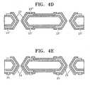
- FIG. 4Dis a sectional view of the second substrate further having a second passivation layer formed to surround almost all of the first passivation layer and the polysilicon interconnect
- FIG. 4Eis a sectional view of the second substrate further having metal/silicon composite layers at the lower part thereof.
- the second substrate 200which includes a signal processing circuit (not shown) for detecting the motion of the suspension structure 13 (see FIG. 3E ) of the microgyroscope, is prepared, and an oxide layer is coated thereon and patterned into an oxide pattern 20.
- the second substrate 200is isotropically etched using the oxide pattern 20 as an etching mask to form through holes 27 through which connection will be made with the outside.
- the oxide pattern 20is removed and the first passivation layer 21 is formed to completely surround the resulting second substrate, as shown in FIG. 4B .
- a polysilicon layeris deposited on the first passivation layer 21 of the second substrate 200 by low pressure chemical vapor deposition (LPCVD) and then patterned, resulting in the polysilicon interconnect 22.
- LPCVDlow pressure chemical vapor deposition
- a silicon oxide layeris coated on the polysilicon interconnect 22 and the first passivation layer 21 by plasma enhanced chemical vapor deposition (PECVD) and patterned to form the second passivation layer 23 having an opening 23' for electrode pads as an opening 23'' as a passage for connection to external circuits.
- PECVDplasma enhanced chemical vapor deposition
- the outer and inner metal/Si composite layers 24 and 25 for interconnection and vacuum packagingare formed.
- the outer metal/Si composite layer 24is for sealing the cavity 150 (see FIG. 2 ) between two substrates.
- the inner metal/Si composite layer 25is adhered to the electrode pad 12 of the first substrate 100 by melting, which allows the interconnection between the electrodes of the suspension structure 13 of the first substrate 100 and the ASIC circuit of the second substrate 200 to be connected to the outside.
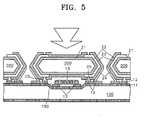
- the electrode pads 12 on the first substrate 100are adhered to the metal/Si composite layers 24 and 25 of the second substrate 200 by a co-melting reaction at low temperatures, such that the first and second substrates 100 and 200 are vacuum sealed while the suspension structure 13 is suspended in a vacuum condition, resulting in a completed device.
- FIGS. 6A and 6Bshow top and sectional views of the wafer having multiple microgyroscopes according to the present invention, respectively.
- reference numeral 180represents a ball for bonding a flip chip and reference numeral 190 represents a dicing line.
- the principle of the high vacuum packaged microgyroscope having the above configurationis as follows. Briefly, the electrode pads 12 of the first substrate 12 and the outer and inner metal/Si composite layers 24 and 25 of the second substrate 200 are melt and cooled using the co-melting properties to seal the cavity 150 therein. At the same time, the interconnections between the electrodes of the suspension structure 13 of the first substrate and the ASIC driving circuit (not shown) of the second substrate 200 are extracted to the outside.
- the co-melting bondingrefers to a kind of bonding technique in which two materials having high but different melting points are melted and bonded at a temperature lower than the melting points.
- Au and Sicontact, they can melt at 363°C.
- the first and second substrates 100 and 200are maintained at 350°C, which is high enough to remove a variety of organic substances, for example, gases adsorbed onto the surface of a thin film, such as oxygen, nitrogen and carbon dioxide, for degassing, and then two substrates 100 and 200 are melted and bonded at 363°C to 400°C.
- This melting and bonding process according to the present inventioncan exclude the degassing of impurities, which is usually performed for a long period of time after such a bonding, and the inner pressure of the space between the first and second substrates 100 and 200 becomes near vacuum levels in the vacuum chamber.
- the electrodes of the suspension structure 13 or the electrodes of the ASICcan be extracted to the top of the second substrate 200 through the polysilicon interconnection 22 of the second substrate 200.
- a substrate with an ASIC circuit for signal processingis mounted onto another substrate including the suspension structure of a microgyroscope in the form of a flip chip.
- the electrodes of the suspension structure and the ASIC circuitcan be exposed to the outside through the polysilicon interconnection interposed between double passivation layers. The short interconnection between the suspension structure and the ASIC circuit can reduce the device in size and prevents generation of noise, thereby increasing signal detection sensitivity.
- the degree of vacuum in the deviceincreases.
- additional processessuch as wire bonding and die bonding, are not required, the manufacturing cost decreases and the size of the product decreases in the order of several square millimeters. This contributes to reducing the size and weight of micro system related applications.
- the first and second substratesare electrically connected and grounded, inflow or outflow of the electric field can be blocked and the generation of noise due to elongated interconnections can be avoided, thereby increasing a signal detection sensitivity.
Landscapes
- Engineering & Computer Science (AREA)
- Physics & Mathematics (AREA)
- General Physics & Mathematics (AREA)
- Microelectronics & Electronic Packaging (AREA)
- Manufacturing & Machinery (AREA)
- Radar, Positioning & Navigation (AREA)
- Remote Sensing (AREA)
- Computer Hardware Design (AREA)
- Pressure Sensors (AREA)
- Gyroscopes (AREA)
Description
- The present invention relates to a high-vacuum packaged microgyroscope according to the preamble of
claim 1 and a method for manufacturing the same. Such microgyroscope may in particular be used for detecting an inertial angular velocity of an object. FIG. 1 illustrates a conventional integrated micro pressure sensor manufactured by anodic bonding. The integrated micro pressure sensor inFIG. 1 includes afirst glass plate 1 as an anodic bonding frame, asilicon substrate 2, a first p+-layer 3 as a vibrating plate for sensing a pressure variation, a second p+-layer 4 as an electrode for measuring a reference electrostatic capacitance, afirst metal electrode 5 for sensing an electrostatic capacitance change, asecond metal electrode 6 for measuring a reference electrostatic capacitance, anASIC circuitry area 7 for processing a variety of signals, agetter 8 for adsorbing gases to decrease the inner pressure near to vacuum levels, a conductive epoxy resin (not shown) for interconnection to external circuitry, and asecond glass plate 10 as another anodic bonding frame. The first andsecond glass plates silicon substrate 2 is interposed, serves as a vacuum case, and is evacuated to a pressure of 10-6 torr (1 torr = 133,32 Pa), thus producing a vacuum, which allows the micro pressure sensor to operate with high accuracy. The micro pressure sensor structure includes a first capacitor structure for sensing a variable electrostatic capacitance, which includes the first p+-layer 3 formed of thesilicon substrate 2 and thefirst metal electrode 5 deposited on thesecond glass plate 10, and a second capacitor structure for sensing a reference electrostatic capacitance change, which includes the second p+-layer 4 formed of thesilicon substrate 2 and thesecond metal electrode 6 deposited on thesecond glass plate 10. The first p+-layer 3 of the first capacitor structure vibrates in accordance with external pressure, thus causing the gap between itself and thefirst metal electrode 5 to vary. Hence, the electrostatic capacitance changes depending upon the pressure applied to the first p+-layer 3. Meanwhile, the second p+-layer 4 of the second capacitor structure remains still without vibration, so that the gap between itself and thesecond metal electrode 6 remains constant, and thus the electrostatic capacitance does not change. Changes in the electrostatic capacitance of the first capacitor structure are measured with respect to the reference electrostatic capacitance of the second capacitor structure, thus enabling measurement of small changes in pressure. Thegetter 8 is a gas adsorbing material for evacuating the space between the first andsecond glass plates - Such a micro pressure sensor operates very accurately in a strong vacuum. The same principle can be applied to microgyroscopes. In addition, microgyroscopes along with their associated signal processing circuitry must be small enough to be used in, for example, camcorders, 3D-mouses for Internet TV, automatic navigation systems and the like. This requirement is a limiting factor in most micro sensors as well as microgyroscopes. For various electrostatic capacitive sensors in which vibration of a microgyroscope enables the sensors to operate, vacuum packaging of the suspension structure is needed for decreased driving voltage of the circuit and increased sensitivity. One of the many approaches for satisfying the need has been to use glass-to-silicon bonding with an anodic bonding technique, which has been conducted primarily in the Esashi Laboratory in Douhuku University in Japan.
- However, such an anodic bonding technique causes contamination of an IC circuit by sodium ions and needs an additional electric field shielding technique for protection of the IC from a high voltage applied during bonding. Therefore, the anodic bonding technique may present a fatal problem in lCs during bonding. In addition, generation of excessive oxygen at bonding sites during bonding hinders the evacuation of the structure, so that there is a room for improvement.
US 5,831,162 discloses a high-vacuum packed microgyroscope according to the preamble ofclaim 1 in which a movable structure comprising a rotationally movable ring is micromachined in a surface of the first substrate which defines a cavity together with the opposing second substrate including a corresponding signal processing circuit for sensing the rotational motion of the ring and joined with the second substrate by a solder bond vacuum seal. The ring is supported by arcuate springs extending from a center post, the springs and the post being also micromachined in said surface of the first substrate. An interconnect of the second substrate for connecting electrodes of the signal processing circuit and the movable structure is provided exclusively within the sealed cavity.EP 0 772 045 A1 discloses a method of fabricating a monolythic motion sensor comprising a movable sensing element micromachined into a surface of a first substrate and sealingly covered in a cavity formed by attaching a second substrate on said surface of the first substrate. Conditioning circuitry on top of the second substrate is electrically connected with bond pads provided outside the sealed cavity on said surface of the first substrate by wire bonding or the like.- Other similar conventional motion sensor structures and fabricating methods are disclosed in
US 5,668,033 and byM.L. Kniffin et al., Packaging for Silicon Micromachined Accelerometers, The International Journal of Microcircuits and Electronic Packaging, Volume 19,. - It is the technical problem underlying the invention to provide a high-vacuum packaged microgyroscope and a method for manufacturing the same, which allow for a relatively small size and weight of the device, low manufacturing effort, and high signal detection sensitivity.
- This problem is solved by providing a high-vacuum packaged microgyroscope according to
claim 1 and a method for manufacturing same according toclaim 10. - Advantageous embodiments of the invention are mentioned in the dependent claims the wording of which is herewith incorporated into the description by reference to avoid unnecessary text repetition.
- According to an embodiment of the invention a substrate with a signal processing ASIC circuit can be mounted on another substrate including a suspension structure of a microgyroscope in the form of a 3-dimensional flip, which decreases the area of the device and the length of interconnection between circuits, and the two substrates are vacuum sealed at the wafer level at low temperatures by a co-melting reaction between a metal and silicon.
- The above objects and advantages of the invention will become more apparent by describing in detail preferred embodiments thereof with reference to the attached drawings in which:
FIG. 1 is a sectional view of a conventional microgyroscope;FIG. 2 is a sectional view of a microgyroscope according to the present invention;FIGS. 3A through 3E are sectional views of successive stages of the fabrication of a suspension structure on the first substrate for the microgyroscope inFIG. 2 ;FIGS. 4A through 4E are sectional views of successive stages of the fabrication of a structure on the second substrate for the microgyroscope inFIG. 2 ;FIG. 5 is a sectional view of a completed microgyroscope according to the present invention, obtained by sealing the first substrate with the suspension structure ofFIG. 3E and the second substrate with a composite layer for interconnection and vacuum packaging by anodic bonding; andFIGS. 6A and6B show top and sectional views of a wafer having multiple microgyroscopes according to the present invention.- A high-vacuum packaged microgyroscope according to the present invention is constructed such that a substrate with a signal processing ASIC circuit is mounted on another substrate with a suspension structure in the form of a 3-dimensional flip, which can decrease the size of the device and the length of interconnection between circuits, and in turn reduce noise. The two substrates are sealed at low temperature, for example, at a temperature of 363°C to 400°C by a co-melting reaction of metal and silicon, for example, gold and silicon, or aluminum and silicon, in a vacuum. In addition, additional packaging processes such as wire bonding or die bonding are not required, which sharply lowers the manufacturing cost. Also, a reduction in the size of the device in the order of several square millimeters contributes to minimizing all devices in micro system related applications.
FIG. 2 is a sectional view of a high-vacuum packaged microgyroscope according to the present invention. InFIG. 2 , the microgyroscope package includes a first substrate (structure wafer) 100 with asuspension structure 13 of a microgyroscope, and a second substrate (cap wafer) 200 with a signal processing circuit (not shown) and apolysilicon interconnection 22 which allows for interconnection to external circuits. Thecap wafer 200 acts as a cap for acavity 150 formed between the first andsecond substrates polysilicon interconnection 22, which allows the first andsecond substrates second substrate 200, and metal/silicon composite layers second substrate 200.- Also, a
suspension structure 13 formed of a second polysilicon is suspended over the groove portion at the center of thefirst substrate 100, which permits the suspension structure to vibrate. For this reason the suspension structure is a vibratory suspension structure, also shortly named a vibratory structure in the present application. The metal/siliconcomposite layer 25 formed at the lower part of thesecond substrate 200 contributes to vacuum sealing thecavity 150 between the first andsecond substrates FIG. 2 ,reference numeral 11 represents a passivation layer of thefirst substrate 100,reference numeral 12 represents an electrode pad for interconnection formed of a first polysilicon,reference numeral 21 represents a first passivation layer of thesecond substrate 200, andreference numeral 23 represents a second passivation layer of thesecond substrate 200. - The first and
second substrates passivation layers second substrates microgyroscope suspension structure 13 is formed over thefirst substrate 100 by a micro machining technique, and thecavity 150 is evacuated to a desired vacuum level, for example, down to 10-6 torr (1 torr = 133,32 Pa). The metal/silicon composite layer 24 for sealing thecavity 150 between the first andsecond substrates - A method for fabricating such a greater vacuum microgyroscope package having the above structure will now be described with reference to
FIGS. 3A through FIG. 5 . First, the fabrication of a suspension structure in the first substrate will be described with reference toFIGS. 3A through 3E . In particular,FIG. 3A is a sectional view of the first substrate for the microgyroscope according to the present invention after the space for a suspension structure has been etched and a passivation layer has been formed on and underneath the first substrate,FIG. 3B is a sectional view of the first substrate with a first polysilicon pattern on the passivation layer,FIG. 3C is a sectional view of the first substrate after a sacrificial layer has been formed on the structure ofFIG. 3B ,FIG. 3D is a sectional view of the first substrate with a suspension structure pattern formed on the sacrificial layer with a second polysilicon pattern, andFIG. 3E is a sectional view of the first substrate with a completed suspension structure obtained by etching away the sacrificial layer. - Initially, as shown in
FIG. 3A , the center area of one surface of thefirst substrate 100 formed of silicon is etched to secure a groove portion 150' where the suspension structure for a microgyroscope is to be formed. Then, thepassivation layer 11 is formed as a protective layer of thefirst substrate 100 on the top and bottom of thefirst silicon wafer 100 with an oxide or nitride film. - Next, as shown in
FIG. 3B , a first polysilicon layer is coated on thepassivation layer 11 and patterned into inner andouter electrode pads 12. Then, a sacrificial layer (PSG) 14 is deposited to cover thepolysilicon electrode pads 12, as shown inFIG. 3C , and then patterned to expose a portion of theelectrode pads 12 which will be an anchor for sustaining the suspension structure. Then, as shown inFIG. 3D , a second polysilicon layer is deposited on the resultant structure and patterned to form thesuspension structure 13. Then, thesacrificial layer 14 is removed from the structure by dry and wet etching, resulting in thecomplete suspension structure 13 shown inFIG. 3E . - With reference to
FIGS. 4A through 4E , the fabrication of a second substrate structure with a signal processing circuit will now be described. In particular,FIG. 4A is a sectional view of the second substrate for the microgyroscope according to the present invention, with an oxide pattern on the top and bottom of the same,FIG. 4B is a sectional view of the second substrate after patterned and surrounded by a first passivation layer as a protective layer against etching,FIG. 4C is a sectional view of the second substrate further having a metal pattern or polysilicon interconnect,FIG. 4D is a sectional view of the second substrate further having a second passivation layer formed to surround almost all of the first passivation layer and the polysilicon interconnect,FIG. 4E is a sectional view of the second substrate further having metal/silicon composite layers at the lower part thereof. - Referring to
FIG. 4A , thesecond substrate 200, which includes a signal processing circuit (not shown) for detecting the motion of the suspension structure 13 (seeFIG. 3E ) of the microgyroscope, is prepared, and an oxide layer is coated thereon and patterned into anoxide pattern 20. - Then, the
second substrate 200 is isotropically etched using theoxide pattern 20 as an etching mask to form throughholes 27 through which connection will be made with the outside. Theoxide pattern 20 is removed and thefirst passivation layer 21 is formed to completely surround the resulting second substrate, as shown inFIG. 4B . - Then, as shown in
FIG. 4C , a polysilicon layer is deposited on thefirst passivation layer 21 of thesecond substrate 200 by low pressure chemical vapor deposition (LPCVD) and then patterned, resulting in thepolysilicon interconnect 22. - Then, as shown in
FIG. 4D , a silicon oxide layer is coated on thepolysilicon interconnect 22 and thefirst passivation layer 21 by plasma enhanced chemical vapor deposition (PECVD) and patterned to form thesecond passivation layer 23 having an opening 23' for electrode pads as an opening 23'' as a passage for connection to external circuits. - Then, as shown in
FIG. 4E , the outer and inner metal/Si composite layers 24 and 25 for interconnection and vacuum packaging are formed. The outer metal/Sicomposite layer 24 is for sealing the cavity 150 (seeFIG. 2 ) between two substrates. The inner metal/Sicomposite layer 25 is adhered to theelectrode pad 12 of thefirst substrate 100 by melting, which allows the interconnection between the electrodes of thesuspension structure 13 of thefirst substrate 100 and the ASIC circuit of thesecond substrate 200 to be connected to the outside. - Finally, as shown in
FIG. 5 , theelectrode pads 12 on thefirst substrate 100 are adhered to the metal/Si composite layers 24 and 25 of thesecond substrate 200 by a co-melting reaction at low temperatures, such that the first andsecond substrates suspension structure 13 is suspended in a vacuum condition, resulting in a completed device. - In manufacturing, many microgyroscopes, which have the configuration mentioned above, are simultaneously formed on a single wafer, as shown in
FIGS. 6A and6B .FIGS. 6A and6B show top and sectional views of the wafer having multiple microgyroscopes according to the present invention, respectively. InFIGS. 6A and6B ,reference numeral 180 represents a ball for bonding a flip chip andreference numeral 190 represents a dicing line. - The principle of the high vacuum packaged microgyroscope having the above configuration is as follows. Briefly, the
electrode pads 12 of thefirst substrate 12 and the outer and inner metal/Si composite layers 24 and 25 of thesecond substrate 200 are melt and cooled using the co-melting properties to seal thecavity 150 therein. At the same time, the interconnections between the electrodes of thesuspension structure 13 of the first substrate and the ASIC driving circuit (not shown) of thesecond substrate 200 are extracted to the outside. The co-melting bonding refers to a kind of bonding technique in which two materials having high but different melting points are melted and bonded at a temperature lower than the melting points. For example, the melting point of gold (Au), which is a commonly used metal, is 1063°C and the melting point of Si is 2410°C. However, when these two materials, Au and Si, contact, they can melt at 363°C. Thus, before the vacuum sealing of the first andsecond substrates second substrates substrates second substrates suspension structure 13 or the electrodes of the ASIC can be extracted to the top of thesecond substrate 200 through thepolysilicon interconnection 22 of thesecond substrate 200. - As described above, in the high-vacuum packaged microgyroscope according to the present invention, a substrate with an ASIC circuit for signal processing is mounted onto another substrate including the suspension structure of a microgyroscope in the form of a flip chip. Also, the electrodes of the suspension structure and the ASIC circuit can be exposed to the outside through the polysilicon interconnection interposed between double passivation layers. The short interconnection between the suspension structure and the ASIC circuit can reduce the device in size and prevents generation of noise, thereby increasing signal detection sensitivity.
- Also, by sealing two substrates at low temperatures, for example, at 363°C to 400°C using the co-melting reaction between metal, for example, Au, and Si in a vacuum, the degree of vacuum in the device increases. Also, additional processes, such as wire bonding and die bonding, are not required, the manufacturing cost decreases and the size of the product decreases in the order of several square millimeters. This contributes to reducing the size and weight of micro system related applications. In addition, when the first and second substrates are electrically connected and grounded, inflow or outflow of the electric field can be blocked and the generation of noise due to elongated interconnections can be avoided, thereby increasing a signal detection sensitivity.
- While this invention has been particularly shown and described with reference to preferred embodiments thereof, it will be understood by those skilled in the art that various changes in form and details may be made therein without departing from the scope of the invention as defined by the appended claims.
Claims (11)
- A high-vacuum packaged microgyroscope comprising- a first substrate (100) including a vibratory structure (13) arranged in a groove cavity (150) formed at one surface thereof so as to be suspended over a groove portion of the first substrate (100), and inner and outer electrode pads (12);- a second substrate (200) including a signal processing circuit for sensing motion of the vibratory structure, an interconnect (22) for connecting electrodes of the signal processing circuit and the vibratory structure, and inner and outer metal/semiconductor composite layers (24, 25), and- a vacuum seal (12, 24, 25) for sealing the cavity thereby forming a vacuum space,- wherein the first and the second substrate (100, 200) are placed such that the vibratory structure (13) and the signal processing circuit thereof face each other,characterized in that- the vacuum seal comprises a co-melting bond between the outer electrode pads (12) and the outer metal/semiconductor composite layers (24), and between the inner electrode pads (12) and the inner metal/semiconductor composite layers (25), and- the interconnect (22) extends between a first and second passivation layer (21, 23) to the top of the second substrate (200) for connecting the electrodes of the vibratory structure and the signal processing circuit to the outside.
- The high-vacuum packaged microgyroscope of claim 1, wherein the suspended vibratory structure (13) is formed of a polysilicon or monosilicon layer.
- The high-vacuum packaged microgyroscope of claim 1 or 2, wherein the inner and outer electrode pads (12) of the suspended vibratory structure (13) are formed of a polysilicon layer, a polysilicon/gold composite layer, or polysilicon/aluminum composite layer.
- The high-vacuum package microgyroscope of any one of claims 1 to 3, wherein the first and the second substrate (100, 200) are formed of silicon.
- The high-vacuum packaged microgyroscope of any of claims 1 to 4, wherein the first and/or the second substrate (100, 200) further comprises a first passivation layer (11, 21) formed of silicon oxide or nitride to protect the respective substrate.
- The high-vacuum packaged microgyroscope of claim 5, wherein the interconnect (22) is formed on both sides and on top and bottom edges of the second substrate (200) surrounded by the first passivation layer (21), the both sides of the second substrate being formed by presence of through holes (27), and a second passivation layer (23) is formed on the interconnect (22)for insulation.
- The high-vacuum packaged microgyroscope of claim 6, wherein the outer metal/semiconductor composite layers (24) are formed on the outer sides of the second passivation layer.
- The high-vacuum packaged microgyroscope of any one of claims 1 to 7, wherein the degree of vacuum of the groove cavity reaches down to 10-6 torr (1 torr = 133,32 Pa).
- The high-vacuum packaged microgyroscope of any one of claims 1 to 8, wherein the inner and outer metal/semiconductor composite layers (24, 25) are formed of a thin Au/Si or Al/Si composite layer so as to be melted and bonded with the inner and outer electrode pads (12) at a low temperature of 363°C to 400°C to create a vacuum space without causing the formation of voids at bonding sites.
- A method for manufacturing a high-vacuum packaged microgyroscope, comprising the following steps:(a) etching a first substrate (100) to form a groove cavity (150) at a region, where a suspended vibratory structure (13) is to be formed, and forming a first passivation layer (11) for protecting the first substrate;(b) depositing a polysilicon layer on the etched surface of the first substrate and patterning the polysilicon layer into inner and outer electrode pads (12);(c) forming the suspended vibratory structure (13) by depositing a sacrificial layer (14) over the inner and outer electrode pads, patterning the sacrificial layer to form openings to be anchors for sustaining the suspended vibratory structure, depositing polysilicon over the opening and the sacrificial layer and patterning the deposited polysilicon layer;(d) removing the sacrificial layer (14) by etching to float the suspended vibratory structure;(e) forming an oxide pattern (20) on a second substrate (200) having a signal processing circuit for sensing the motion of the suspended vibratory structure;(f) patterning the second substrate (200) using the oxide pattern (20) as an etching mask to form through holes (27) for interconnection to the outside, removing the oxide pattern, and forming a first passivation layer (21) for protecting the entire surface of the second substrate;(g) forming an interconnect (22) by depositing a polysilicon layer to cover both sides and the top and bottom edges of the second substrate surrounded by the first passivation layer, and patterning the polysilicon layer;(h) depositing a second passivation layer (23) to cover the interconnect and the second substrate and patterning the second passivation layer to form openings (23') for interconnection to the outside;(i) forming an inner metal/semiconductor composite layer (25) for connection through the openings (23') to the interconnect (22), and an outer metal/semiconductor composite layer (24) for vacuum packaging on the second passivation layer (23); and(j) vacuum sealing the first and the second substrates (100, 200) by co-melting bond between the inner electrode pads (12)of the first substrate (100) and the inner metal/semiconductor composite layers (25), and between the outer electrode pads (12) of the first substrate (100) and the outer metal/semiconductor composite layers (24) of the second substrate (200), to maintain the cavity (150) with the suspended vibratory structure (13) in a vacuum condition.
- The method of claim 10, wherein
in the step (b) the inner and outer electrode pads (12) of the suspended vibratory structure (13) are formed of a polysilicon layer, a polysilicon/gold composite layer, or a polysiliconl/aluminum composite layer, and/or
in the step (g) the polysilicon layer is deposited by low pressure chemical vapor deposition (LPCVD), and/or
in the step (h) the second passivation layer (23) is deposited by plasma enhanced chemical vapor deposition (PECVD), and/or
in the step (i) the inner and outer metal/semiconductor composite layers (24, 25) are formed of a Au/Si or Al/Si composite layer, and/or
in the step (j) the melting and bonding are performed at a low temperature of 363 to 400°C, and/or the degree of vacuum in the cavity reaches down to 10-6 torr (1 torr = 133,32 Pa).
Applications Claiming Priority (2)
| Application Number | Priority Date | Filing Date | Title |
|---|---|---|---|
| KR10-1999-0047965AKR100413789B1 (en) | 1999-11-01 | 1999-11-01 | High vacuum packaging microgyroscope and manufacturing method thereof |
| KR9947965 | 1999-11-01 |
Publications (2)
| Publication Number | Publication Date |
|---|---|
| EP1096259A1 EP1096259A1 (en) | 2001-05-02 |
| EP1096259B1true EP1096259B1 (en) | 2008-12-03 |
Family
ID=19618019
Family Applications (1)
| Application Number | Title | Priority Date | Filing Date |
|---|---|---|---|
| EP00122364AExpired - LifetimeEP1096259B1 (en) | 1999-11-01 | 2000-10-25 | High-vacuum packaged microgyroscope and method for manufacturing the same |
Country Status (5)
| Country | Link |
|---|---|
| US (2) | US6559487B1 (en) |
| EP (1) | EP1096259B1 (en) |
| JP (1) | JP2001189467A (en) |
| KR (1) | KR100413789B1 (en) |
| DE (1) | DE60040959D1 (en) |
Cited By (37)
| Publication number | Priority date | Publication date | Assignee | Title |
|---|---|---|---|---|
| US7463499B2 (en) | 2005-10-31 | 2008-12-09 | Avago Technologies General Ip (Singapore) Pte Ltd. | AC-DC power converter |
| US7479685B2 (en) | 2006-03-10 | 2009-01-20 | Avago Technologies General Ip (Singapore) Pte. Ltd. | Electronic device on substrate with cavity and mitigated parasitic leakage path |
| US7508286B2 (en) | 2006-09-28 | 2009-03-24 | Avago Technologies Wireless Ip (Singapore) Pte. Ltd. | HBAR oscillator and method of manufacture |
| US7525398B2 (en) | 2005-10-18 | 2009-04-28 | Avago Technologies General Ip (Singapore) Pte. Ltd. | Acoustically communicating data signals across an electrical isolation barrier |
| US7561009B2 (en) | 2005-11-30 | 2009-07-14 | Avago Technologies General Ip (Singapore) Pte. Ltd. | Film bulk acoustic resonator (FBAR) devices with temperature compensation |
| US7615833B2 (en) | 2004-07-13 | 2009-11-10 | Avago Technologies Wireless Ip (Singapore) Pte. Ltd. | Film bulk acoustic resonator package and method of fabricating same |
| US7629865B2 (en) | 2006-05-31 | 2009-12-08 | Avago Technologies Wireless Ip (Singapore) Pte. Ltd. | Piezoelectric resonator structures and electrical filters |
| US7675390B2 (en) | 2005-10-18 | 2010-03-09 | Avago Technologies Wireless Ip (Singapore) Pte. Ltd. | Acoustic galvanic isolator incorporating single decoupled stacked bulk acoustic resonator |
| US7714684B2 (en) | 2004-10-01 | 2010-05-11 | Avago Technologies Wireless Ip (Singapore) Pte. Ltd. | Acoustic resonator performance enhancement using alternating frame structure |
| US7732977B2 (en) | 2008-04-30 | 2010-06-08 | Avago Technologies Wireless Ip (Singapore) | Transceiver circuit for film bulk acoustic resonator (FBAR) transducers |
| US7737807B2 (en) | 2005-10-18 | 2010-06-15 | Avago Technologies Wireless Ip (Singapore) Pte. Ltd. | Acoustic galvanic isolator incorporating series-connected decoupled stacked bulk acoustic resonators |
| US7746677B2 (en) | 2006-03-09 | 2010-06-29 | Avago Technologies Wireless Ip (Singapore) Pte. Ltd. | AC-DC converter circuit and power supply |
| US7791434B2 (en) | 2004-12-22 | 2010-09-07 | Avago Technologies Wireless Ip (Singapore) Pte. Ltd. | Acoustic resonator performance enhancement using selective metal etch and having a trench in the piezoelectric |
| US7791435B2 (en) | 2007-09-28 | 2010-09-07 | Avago Technologies Wireless Ip (Singapore) Pte. Ltd. | Single stack coupled resonators having differential output |
| US7802349B2 (en) | 2003-03-07 | 2010-09-28 | Avago Technologies Wireless Ip (Singapore) Pte. Ltd. | Manufacturing process for thin film bulk acoustic resonator (FBAR) filters |
| US7855618B2 (en) | 2008-04-30 | 2010-12-21 | Avago Technologies Wireless Ip (Singapore) Pte. Ltd. | Bulk acoustic resonator electrical impedance transformers |
| US7868522B2 (en) | 2005-09-09 | 2011-01-11 | Avago Technologies Wireless Ip (Singapore) Pte. Ltd. | Adjusted frequency temperature coefficient resonator |
| US8143082B2 (en) | 2004-12-15 | 2012-03-27 | Avago Technologies Wireless Ip (Singapore) Pte. Ltd. | Wafer bonding of micro-electro mechanical systems to active circuitry |
| US8193877B2 (en) | 2009-11-30 | 2012-06-05 | Avago Technologies Wireless Ip (Singapore) Pte. Ltd. | Duplexer with negative phase shifting circuit |
| US8230562B2 (en) | 2005-04-06 | 2012-07-31 | Avago Technologies Wireless Ip (Singapore) Pte. Ltd. | Method of fabricating an acoustic resonator comprising a filled recessed region |
| US8248185B2 (en) | 2009-06-24 | 2012-08-21 | Avago Technologies Wireless Ip (Singapore) Pte. Ltd. | Acoustic resonator structure comprising a bridge |
| US8350445B1 (en) | 2011-06-16 | 2013-01-08 | Avago Technologies Wireless Ip (Singapore) Pte. Ltd. | Bulk acoustic resonator comprising non-piezoelectric layer and bridge |
| US8575820B2 (en) | 2011-03-29 | 2013-11-05 | Avago Technologies General Ip (Singapore) Pte. Ltd. | Stacked bulk acoustic resonator |
| US8796904B2 (en) | 2011-10-31 | 2014-08-05 | Avago Technologies General Ip (Singapore) Pte. Ltd. | Bulk acoustic resonator comprising piezoelectric layer and inverse piezoelectric layer |
| US8902023B2 (en) | 2009-06-24 | 2014-12-02 | Avago Technologies General Ip (Singapore) Pte. Ltd. | Acoustic resonator structure having an electrode with a cantilevered portion |
| US8922302B2 (en) | 2011-08-24 | 2014-12-30 | Avago Technologies General Ip (Singapore) Pte. Ltd. | Acoustic resonator formed on a pedestal |
| US8962443B2 (en) | 2011-01-31 | 2015-02-24 | Avago Technologies General Ip (Singapore) Pte. Ltd. | Semiconductor device having an airbridge and method of fabricating the same |
| US8981876B2 (en) | 2004-11-15 | 2015-03-17 | Avago Technologies General Ip (Singapore) Pte. Ltd. | Piezoelectric resonator structures and electrical filters having frame elements |
| US9048812B2 (en) | 2011-02-28 | 2015-06-02 | Avago Technologies General Ip (Singapore) Pte. Ltd. | Bulk acoustic wave resonator comprising bridge formed within piezoelectric layer |
| US9083302B2 (en) | 2011-02-28 | 2015-07-14 | Avago Technologies General Ip (Singapore) Pte. Ltd. | Stacked bulk acoustic resonator comprising a bridge and an acoustic reflector along a perimeter of the resonator |
| US9136818B2 (en) | 2011-02-28 | 2015-09-15 | Avago Technologies General Ip (Singapore) Pte. Ltd. | Stacked acoustic resonator comprising a bridge |
| US9148117B2 (en) | 2011-02-28 | 2015-09-29 | Avago Technologies General Ip (Singapore) Pte. Ltd. | Coupled resonator filter comprising a bridge and frame elements |
| US9154112B2 (en) | 2011-02-28 | 2015-10-06 | Avago Technologies General Ip (Singapore) Pte. Ltd. | Coupled resonator filter comprising a bridge |
| US9203374B2 (en) | 2011-02-28 | 2015-12-01 | Avago Technologies General Ip (Singapore) Pte. Ltd. | Film bulk acoustic resonator comprising a bridge |
| US9243316B2 (en) | 2010-01-22 | 2016-01-26 | Avago Technologies General Ip (Singapore) Pte. Ltd. | Method of fabricating piezoelectric material with selected c-axis orientation |
| US9425764B2 (en) | 2012-10-25 | 2016-08-23 | Avago Technologies General Ip (Singapore) Pte. Ltd. | Accoustic resonator having composite electrodes with integrated lateral features |
| US9444426B2 (en) | 2012-10-25 | 2016-09-13 | Avago Technologies General Ip (Singapore) Pte. Ltd. | Accoustic resonator having integrated lateral feature and temperature compensation feature |
Families Citing this family (61)
| Publication number | Priority date | Publication date | Assignee | Title |
|---|---|---|---|---|
| FR2773261B1 (en) | 1997-12-30 | 2000-01-28 | Commissariat Energie Atomique | METHOD FOR THE TRANSFER OF A THIN FILM COMPRISING A STEP OF CREATING INCLUSIONS |
| DE10153319B4 (en)* | 2001-10-29 | 2011-02-17 | austriamicrosystems AG, Schloss Premstätten | microsensor |
| FR2833106B1 (en)* | 2001-12-03 | 2005-02-25 | St Microelectronics Sa | INTEGRATED CIRCUIT INCLUDING AN AUXILIARY COMPONENT, FOR EXAMPLE A PASSIVE COMPONENT OR AN ELECTROMECHANICAL MICROSYSTEM, PROVIDED ABOVE AN ELECTRONIC CHIP, AND CORRESPONDING MANUFACTURING METHOD |
| DE10216267B4 (en)* | 2002-04-12 | 2005-04-14 | Infineon Technologies Ag | Method for producing a housing for a chip with a micromechanical structure |
| FR2848339B1 (en)* | 2002-12-05 | 2005-08-26 | St Microelectronics Sa | METHOD FOR ADHESIONING TWO ELEMENTS, IN PARTICULAR AN INTEGRATED CIRCUIT, FOR EXAMPLE RESONATOR ENCAPSULATION, AND CORRESPONDING INTEGRATED CIRCUIT |
| FR2848336B1 (en) | 2002-12-09 | 2005-10-28 | Commissariat Energie Atomique | METHOD FOR PRODUCING A STRESS STRUCTURE FOR DISSOCIATING |
| US6812558B2 (en)* | 2003-03-26 | 2004-11-02 | Northrop Grumman Corporation | Wafer scale package and method of assembly |
| JP4238724B2 (en) | 2003-03-27 | 2009-03-18 | 株式会社デンソー | Semiconductor device |
| FR2856844B1 (en)* | 2003-06-24 | 2006-02-17 | Commissariat Energie Atomique | HIGH PERFORMANCE CHIP INTEGRATED CIRCUIT |
| US6774327B1 (en)* | 2003-09-24 | 2004-08-10 | Agilent Technologies, Inc. | Hermetic seals for electronic components |
| FR2861497B1 (en) | 2003-10-28 | 2006-02-10 | Soitec Silicon On Insulator | METHOD FOR CATASTROPHIC TRANSFER OF A FINE LAYER AFTER CO-IMPLANTATION |
| EP1528677B1 (en) | 2003-10-30 | 2006-05-10 | Agilent Technologies, Inc. | Film acoustically-coupled transformer with two reverse c-axis piezoelectric elements |
| US7362198B2 (en) | 2003-10-30 | 2008-04-22 | Avago Technologies Wireless Ip (Singapore) Pte. Ltd | Pass bandwidth control in decoupled stacked bulk acoustic resonator devices |
| US7358831B2 (en) | 2003-10-30 | 2008-04-15 | Avago Technologies Wireless Ip (Singapore) Pte. Ltd. | Film bulk acoustic resonator (FBAR) devices with simplified packaging |
| US7019605B2 (en) | 2003-10-30 | 2006-03-28 | Larson Iii John D | Stacked bulk acoustic resonator band-pass filter with controllable pass bandwidth |
| US6946928B2 (en) | 2003-10-30 | 2005-09-20 | Agilent Technologies, Inc. | Thin-film acoustically-coupled transformer |
| US7291513B2 (en)* | 2003-12-15 | 2007-11-06 | Dalsa Semiconductor Inc. | Hermetic wafer-level packaging for MEMS devices with low-temperature metallurgy |
| US7960209B2 (en)* | 2004-01-29 | 2011-06-14 | Diodes, Inc. | Semiconductor device assembly process |
| JP4570912B2 (en)* | 2004-06-23 | 2010-10-27 | セイコーインスツル株式会社 | Vacuum-sealed inertial force sensor |
| US7183622B2 (en)* | 2004-06-30 | 2007-02-27 | Intel Corporation | Module integrating MEMS and passive components |
| JP4343044B2 (en)* | 2004-06-30 | 2009-10-14 | 新光電気工業株式会社 | Interposer, manufacturing method thereof, and semiconductor device |
| JP4808729B2 (en)* | 2004-11-12 | 2011-11-02 | アナログ デバイシーズ インク | Spacing butted component structure |
| DE102004058880B4 (en)* | 2004-12-06 | 2007-12-13 | Austriamicrosystems Ag | Integrated microsensor and method of manufacture |
| US20060125084A1 (en)* | 2004-12-15 | 2006-06-15 | Fazzio Ronald S | Integration of micro-electro mechanical systems and active circuitry |
| JP5074693B2 (en)* | 2005-01-26 | 2012-11-14 | パナソニック株式会社 | Micro electromechanical device |
| US7427819B2 (en) | 2005-03-04 | 2008-09-23 | Avago Wireless Ip Pte Ltd | Film-bulk acoustic wave resonator with motion plate and method |
| US7436269B2 (en)* | 2005-04-18 | 2008-10-14 | Avago Technologies Wireless Ip (Singapore) Pte. Ltd. | Acoustically coupled resonators and method of making the same |
| US7419853B2 (en)* | 2005-08-11 | 2008-09-02 | Hymite A/S | Method of fabrication for chip scale package for a micro component |
| FR2889887B1 (en) | 2005-08-16 | 2007-11-09 | Commissariat Energie Atomique | METHOD FOR DEFERING A THIN LAYER ON A SUPPORT |
| FR2891281B1 (en) | 2005-09-28 | 2007-12-28 | Commissariat Energie Atomique | METHOD FOR MANUFACTURING A THIN FILM ELEMENT |
| US7391286B2 (en) | 2005-10-06 | 2008-06-24 | Avago Wireless Ip Pte Ltd | Impedance matching and parasitic capacitor resonance of FBAR resonators and coupled filters |
| US7423503B2 (en) | 2005-10-18 | 2008-09-09 | Avago Technologies Wireless Ip (Singapore) Pte. Ltd. | Acoustic galvanic isolator incorporating film acoustically-coupled transformer |
| US7425787B2 (en) | 2005-10-18 | 2008-09-16 | Avago Technologies Wireless Ip (Singapore) Pte. Ltd. | Acoustic galvanic isolator incorporating single insulated decoupled stacked bulk acoustic resonator with acoustically-resonant electrical insulator |
| US7491567B2 (en) | 2005-11-22 | 2009-02-17 | Honeywell International Inc. | MEMS device packaging methods |
| JP5069410B2 (en)* | 2005-11-25 | 2012-11-07 | パナソニック株式会社 | Sensor element |
| WO2008054430A2 (en)* | 2005-12-02 | 2008-05-08 | The Regents Of The University Of California | Nanostructure-based memory |
| US7612636B2 (en) | 2006-01-30 | 2009-11-03 | Avago Technologies Wireless Ip (Singapore) Pte. Ltd. | Impedance transforming bulk acoustic wave baluns |
| US20070210748A1 (en)* | 2006-03-09 | 2007-09-13 | Mark Unkrich | Power supply and electronic device having integrated power supply |
| JP5011820B2 (en)* | 2006-05-24 | 2012-08-29 | オムロン株式会社 | Multilayer device and manufacturing method thereof |
| FR2910179B1 (en) | 2006-12-19 | 2009-03-13 | Commissariat Energie Atomique | METHOD FOR MANUFACTURING THIN LAYERS OF GaN BY IMPLANTATION AND RECYCLING OF A STARTING SUBSTRATE |
| WO2008139701A1 (en)* | 2007-04-27 | 2008-11-20 | Panasonic Corporation | Electronic component mounting body and electronic component with solder bump and method for manufacturing them |
| US20090079514A1 (en)* | 2007-09-24 | 2009-03-26 | Tiberiu Jamneala | Hybrid acoustic resonator-based filters |
| FR2938974B1 (en)* | 2008-11-25 | 2011-01-21 | Tronic S Microsystems | MICROELECTROMECHANICAL COMPONENT AND METHOD OF MANUFACTURE |
| FR2947098A1 (en) | 2009-06-18 | 2010-12-24 | Commissariat Energie Atomique | METHOD OF TRANSFERRING A THIN LAYER TO A TARGET SUBSTRATE HAVING A THERMAL EXPANSION COEFFICIENT DIFFERENT FROM THAT OF THE THIN LAYER |
| RU2435294C2 (en)* | 2009-12-11 | 2011-11-27 | Федеральное Государственное Учреждение "Научно-Производственный Комплекс "Технологический Центр" Московского Государственного Института Электронной Техники" | Method to make integral high-q silicon micromechanical resonator |
| US9401692B2 (en) | 2012-10-29 | 2016-07-26 | Avago Technologies General Ip (Singapore) Pte. Ltd. | Acoustic resonator having collar structure |
| US9490771B2 (en) | 2012-10-29 | 2016-11-08 | Avago Technologies General Ip (Singapore) Pte. Ltd. | Acoustic resonator comprising collar and frame |
| US9490418B2 (en) | 2011-03-29 | 2016-11-08 | Avago Technologies General Ip (Singapore) Pte. Ltd. | Acoustic resonator comprising collar and acoustic reflector with temperature compensating layer |
| US8724832B2 (en) | 2011-08-30 | 2014-05-13 | Qualcomm Mems Technologies, Inc. | Piezoelectric microphone fabricated on glass |
| US8824706B2 (en) | 2011-08-30 | 2014-09-02 | Qualcomm Mems Technologies, Inc. | Piezoelectric microphone fabricated on glass |
| US8811636B2 (en) | 2011-11-29 | 2014-08-19 | Qualcomm Mems Technologies, Inc. | Microspeaker with piezoelectric, metal and dielectric membrane |
| DE102012013096A1 (en) | 2012-06-30 | 2014-01-02 | X-Fab Semiconductor Foundries Ag | Method for manufacturing micro-electromechanical system (MEMS), involves forming electrical interconnections between cavity disc and circuitry disc, and enabling completion of element by standard methods and connection technique |
| US9385684B2 (en) | 2012-10-23 | 2016-07-05 | Avago Technologies General Ip (Singapore) Pte. Ltd. | Acoustic resonator having guard ring |
| US9556017B2 (en)* | 2013-06-25 | 2017-01-31 | Analog Devices, Inc. | Apparatus and method for preventing stiction of MEMS devices encapsulated by active circuitry |
| US10081535B2 (en) | 2013-06-25 | 2018-09-25 | Analog Devices, Inc. | Apparatus and method for shielding and biasing in MEMS devices encapsulated by active circuitry |
| US9574959B2 (en)* | 2014-09-02 | 2017-02-21 | Apple Inc. | Various stress free sensor packages using wafer level supporting die and air gap technique |
| US9604841B2 (en)* | 2014-11-06 | 2017-03-28 | Analog Devices, Inc. | MEMS sensor cap with multiple isolated electrodes |
| CN106257254B (en)* | 2015-06-22 | 2020-03-20 | 意法半导体股份有限公司 | Pressure sensor generating a transducing signal with reduced ambient temperature dependency and method of manufacturing the same |
| JP6641899B2 (en) | 2015-11-04 | 2020-02-05 | セイコーエプソン株式会社 | Physical quantity sensor, physical quantity sensor device, electronic equipment and moving object |
| CN112034204A (en)* | 2020-08-01 | 2020-12-04 | 沈阳工业大学 | Linked contact capacitance type acceleration sensitive chip and manufacturing method thereof |
| CN115676766A (en)* | 2022-09-28 | 2023-02-03 | 北京时代民芯科技有限公司 | Three-axis MEMS gyroscope integrated micro system and manufacturing method thereof |
Citations (1)
| Publication number | Priority date | Publication date | Assignee | Title |
|---|---|---|---|---|
| US5831162A (en)* | 1997-01-21 | 1998-11-03 | Delco Electronics Corporation | Silicon micromachined motion sensor and method of making |
Family Cites Families (7)
| Publication number | Priority date | Publication date | Assignee | Title |
|---|---|---|---|---|
| US5216490A (en)* | 1988-01-13 | 1993-06-01 | Charles Stark Draper Laboratory, Inc. | Bridge electrodes for microelectromechanical devices |
| US5591000A (en) | 1995-01-05 | 1997-01-07 | Siemens Aktiengesellschaft | Compressor unit |
| JP3613838B2 (en)* | 1995-05-18 | 2005-01-26 | 株式会社デンソー | Manufacturing method of semiconductor device |
| US5721162A (en)* | 1995-11-03 | 1998-02-24 | Delco Electronics Corporation | All-silicon monolithic motion sensor with integrated conditioning circuit |
| US6109113A (en)* | 1998-06-11 | 2000-08-29 | Delco Electronics Corp. | Silicon micromachined capacitive pressure sensor and method of manufacture |
| US6252229B1 (en)* | 1998-07-10 | 2001-06-26 | Boeing North American, Inc. | Sealed-cavity microstructure and microbolometer and associated fabrication methods |
| KR100343211B1 (en)* | 1999-11-04 | 2002-07-10 | 윤종용 | Fablication method of Micro Electromechanical System structure which can be packaged in the state of wafer level |
- 1999
- 1999-11-01KRKR10-1999-0047965Apatent/KR100413789B1/ennot_activeExpired - Fee Related
- 2000
- 2000-10-25EPEP00122364Apatent/EP1096259B1/ennot_activeExpired - Lifetime
- 2000-10-25DEDE60040959Tpatent/DE60040959D1/ennot_activeExpired - Fee Related
- 2000-11-01JPJP2000335067Apatent/JP2001189467A/ennot_activeWithdrawn
- 2000-11-01USUS09/702,846patent/US6559487B1/ennot_activeExpired - Lifetime
- 2003
- 2003-03-14USUS10/387,541patent/US6767757B2/ennot_activeExpired - Lifetime
Patent Citations (1)
| Publication number | Priority date | Publication date | Assignee | Title |
|---|---|---|---|---|
| US5831162A (en)* | 1997-01-21 | 1998-11-03 | Delco Electronics Corporation | Silicon micromachined motion sensor and method of making |
Non-Patent Citations (1)
| Title |
|---|
| KNIFFIN M.-L.: "Packaging for Silicon Micromachined Accelerometers", INTERNATIONAL JOURNAL OF MICROCIRCUITS AND ELECTRONIC PACKAGING, vol. 19, no. 1, 1996, pages 75 - 86, XP000639470* |
Cited By (41)
| Publication number | Priority date | Publication date | Assignee | Title |
|---|---|---|---|---|
| US7802349B2 (en) | 2003-03-07 | 2010-09-28 | Avago Technologies Wireless Ip (Singapore) Pte. Ltd. | Manufacturing process for thin film bulk acoustic resonator (FBAR) filters |
| US7615833B2 (en) | 2004-07-13 | 2009-11-10 | Avago Technologies Wireless Ip (Singapore) Pte. Ltd. | Film bulk acoustic resonator package and method of fabricating same |
| US7714684B2 (en) | 2004-10-01 | 2010-05-11 | Avago Technologies Wireless Ip (Singapore) Pte. Ltd. | Acoustic resonator performance enhancement using alternating frame structure |
| US8981876B2 (en) | 2004-11-15 | 2015-03-17 | Avago Technologies General Ip (Singapore) Pte. Ltd. | Piezoelectric resonator structures and electrical filters having frame elements |
| US8143082B2 (en) | 2004-12-15 | 2012-03-27 | Avago Technologies Wireless Ip (Singapore) Pte. Ltd. | Wafer bonding of micro-electro mechanical systems to active circuitry |
| US7791434B2 (en) | 2004-12-22 | 2010-09-07 | Avago Technologies Wireless Ip (Singapore) Pte. Ltd. | Acoustic resonator performance enhancement using selective metal etch and having a trench in the piezoelectric |
| US8188810B2 (en) | 2004-12-22 | 2012-05-29 | Avago Technologies Wireless Ip (Singapore) Pte. Ltd. | Acoustic resonator performance enhancement using selective metal etch |
| US8230562B2 (en) | 2005-04-06 | 2012-07-31 | Avago Technologies Wireless Ip (Singapore) Pte. Ltd. | Method of fabricating an acoustic resonator comprising a filled recessed region |
| US7868522B2 (en) | 2005-09-09 | 2011-01-11 | Avago Technologies Wireless Ip (Singapore) Pte. Ltd. | Adjusted frequency temperature coefficient resonator |
| US7737807B2 (en) | 2005-10-18 | 2010-06-15 | Avago Technologies Wireless Ip (Singapore) Pte. Ltd. | Acoustic galvanic isolator incorporating series-connected decoupled stacked bulk acoustic resonators |
| US7675390B2 (en) | 2005-10-18 | 2010-03-09 | Avago Technologies Wireless Ip (Singapore) Pte. Ltd. | Acoustic galvanic isolator incorporating single decoupled stacked bulk acoustic resonator |
| US7525398B2 (en) | 2005-10-18 | 2009-04-28 | Avago Technologies General Ip (Singapore) Pte. Ltd. | Acoustically communicating data signals across an electrical isolation barrier |
| US7852644B2 (en) | 2005-10-31 | 2010-12-14 | Avago Technologies General Ip (Singapore) Pte. Ltd. | AC-DC power converter |
| US7463499B2 (en) | 2005-10-31 | 2008-12-09 | Avago Technologies General Ip (Singapore) Pte Ltd. | AC-DC power converter |
| US7561009B2 (en) | 2005-11-30 | 2009-07-14 | Avago Technologies General Ip (Singapore) Pte. Ltd. | Film bulk acoustic resonator (FBAR) devices with temperature compensation |
| US7746677B2 (en) | 2006-03-09 | 2010-06-29 | Avago Technologies Wireless Ip (Singapore) Pte. Ltd. | AC-DC converter circuit and power supply |
| US8238129B2 (en) | 2006-03-09 | 2012-08-07 | Avago Technologies Wireless Ip (Singapore) Pte. Ltd. | AC-DC converter circuit and power supply |
| US7479685B2 (en) | 2006-03-10 | 2009-01-20 | Avago Technologies General Ip (Singapore) Pte. Ltd. | Electronic device on substrate with cavity and mitigated parasitic leakage path |
| US8080854B2 (en) | 2006-03-10 | 2011-12-20 | Avago Technologies General Ip (Singapore) Pte. Ltd. | Electronic device on substrate with cavity and mitigated parasitic leakage path |
| US7629865B2 (en) | 2006-05-31 | 2009-12-08 | Avago Technologies Wireless Ip (Singapore) Pte. Ltd. | Piezoelectric resonator structures and electrical filters |
| US7508286B2 (en) | 2006-09-28 | 2009-03-24 | Avago Technologies Wireless Ip (Singapore) Pte. Ltd. | HBAR oscillator and method of manufacture |
| US7791435B2 (en) | 2007-09-28 | 2010-09-07 | Avago Technologies Wireless Ip (Singapore) Pte. Ltd. | Single stack coupled resonators having differential output |
| US7855618B2 (en) | 2008-04-30 | 2010-12-21 | Avago Technologies Wireless Ip (Singapore) Pte. Ltd. | Bulk acoustic resonator electrical impedance transformers |
| US7732977B2 (en) | 2008-04-30 | 2010-06-08 | Avago Technologies Wireless Ip (Singapore) | Transceiver circuit for film bulk acoustic resonator (FBAR) transducers |
| US8248185B2 (en) | 2009-06-24 | 2012-08-21 | Avago Technologies Wireless Ip (Singapore) Pte. Ltd. | Acoustic resonator structure comprising a bridge |
| US8902023B2 (en) | 2009-06-24 | 2014-12-02 | Avago Technologies General Ip (Singapore) Pte. Ltd. | Acoustic resonator structure having an electrode with a cantilevered portion |
| US8193877B2 (en) | 2009-11-30 | 2012-06-05 | Avago Technologies Wireless Ip (Singapore) Pte. Ltd. | Duplexer with negative phase shifting circuit |
| US9243316B2 (en) | 2010-01-22 | 2016-01-26 | Avago Technologies General Ip (Singapore) Pte. Ltd. | Method of fabricating piezoelectric material with selected c-axis orientation |
| US8962443B2 (en) | 2011-01-31 | 2015-02-24 | Avago Technologies General Ip (Singapore) Pte. Ltd. | Semiconductor device having an airbridge and method of fabricating the same |
| US9148117B2 (en) | 2011-02-28 | 2015-09-29 | Avago Technologies General Ip (Singapore) Pte. Ltd. | Coupled resonator filter comprising a bridge and frame elements |
| US9048812B2 (en) | 2011-02-28 | 2015-06-02 | Avago Technologies General Ip (Singapore) Pte. Ltd. | Bulk acoustic wave resonator comprising bridge formed within piezoelectric layer |
| US9083302B2 (en) | 2011-02-28 | 2015-07-14 | Avago Technologies General Ip (Singapore) Pte. Ltd. | Stacked bulk acoustic resonator comprising a bridge and an acoustic reflector along a perimeter of the resonator |
| US9136818B2 (en) | 2011-02-28 | 2015-09-15 | Avago Technologies General Ip (Singapore) Pte. Ltd. | Stacked acoustic resonator comprising a bridge |
| US9154112B2 (en) | 2011-02-28 | 2015-10-06 | Avago Technologies General Ip (Singapore) Pte. Ltd. | Coupled resonator filter comprising a bridge |
| US9203374B2 (en) | 2011-02-28 | 2015-12-01 | Avago Technologies General Ip (Singapore) Pte. Ltd. | Film bulk acoustic resonator comprising a bridge |
| US8575820B2 (en) | 2011-03-29 | 2013-11-05 | Avago Technologies General Ip (Singapore) Pte. Ltd. | Stacked bulk acoustic resonator |
| US8350445B1 (en) | 2011-06-16 | 2013-01-08 | Avago Technologies Wireless Ip (Singapore) Pte. Ltd. | Bulk acoustic resonator comprising non-piezoelectric layer and bridge |
| US8922302B2 (en) | 2011-08-24 | 2014-12-30 | Avago Technologies General Ip (Singapore) Pte. Ltd. | Acoustic resonator formed on a pedestal |
| US8796904B2 (en) | 2011-10-31 | 2014-08-05 | Avago Technologies General Ip (Singapore) Pte. Ltd. | Bulk acoustic resonator comprising piezoelectric layer and inverse piezoelectric layer |
| US9425764B2 (en) | 2012-10-25 | 2016-08-23 | Avago Technologies General Ip (Singapore) Pte. Ltd. | Accoustic resonator having composite electrodes with integrated lateral features |
| US9444426B2 (en) | 2012-10-25 | 2016-09-13 | Avago Technologies General Ip (Singapore) Pte. Ltd. | Accoustic resonator having integrated lateral feature and temperature compensation feature |
Also Published As
| Publication number | Publication date |
|---|---|
| KR20010044908A (en) | 2001-06-05 |
| US6767757B2 (en) | 2004-07-27 |
| US20030132493A1 (en) | 2003-07-17 |
| KR100413789B1 (en) | 2003-12-31 |
| JP2001189467A (en) | 2001-07-10 |
| DE60040959D1 (en) | 2009-01-15 |
| US6559487B1 (en) | 2003-05-06 |
| EP1096259A1 (en) | 2001-05-02 |
Similar Documents
| Publication | Publication Date | Title |
|---|---|---|
| EP1096259B1 (en) | High-vacuum packaged microgyroscope and method for manufacturing the same | |
| US6323550B1 (en) | Package for sealing an integrated circuit die | |
| US7563632B2 (en) | Methods for packaging and sealing an integrated circuit die | |
| US8186221B2 (en) | Vertically integrated MEMS acceleration transducer | |
| EP0886144B1 (en) | A hermetically sealed sensor with a movable microstructure | |
| US8220330B2 (en) | Vertically integrated MEMS sensor device with multi-stimulus sensing | |
| US8100012B2 (en) | MEMS sensor with cap electrode | |
| EP1953815B1 (en) | Wafer level package structure, and sensor device obtained from the same package structure | |
| US20070114643A1 (en) | Mems flip-chip packaging | |
| EP2573514B1 (en) | Composite sensor and method for manufacturing same | |
| JP4404143B2 (en) | Semiconductor device and manufacturing method thereof | |
| EP3076146B1 (en) | Pressure sensor | |
| WO2013080238A1 (en) | Composite sensor and method of manufacture therefor | |
| TW201307183A (en) | Metal thin shield on electrical device | |
| US20220260606A1 (en) | Sensor packages | |
| JPH09292409A (en) | Acceleration sensor | |
| KR100506073B1 (en) | A vacuum packaged microgyroscope and a fabricating method thereof | |
| JP2002280470A (en) | Semiconductor device and manufacturing method thereof | |
| KR19980086900A (en) | High Vacuum Packaging 2-axis Micro Gyroscope and Manufacturing Method Thereof | |
| CN119218934A (en) | Micro-electromechanical sensor device with wafer-level integration and corresponding manufacturing method | |
| JPWO2013080238A1 (en) | Composite sensor and manufacturing method thereof |
Legal Events
| Date | Code | Title | Description |
|---|---|---|---|
| PUAI | Public reference made under article 153(3) epc to a published international application that has entered the european phase | Free format text:ORIGINAL CODE: 0009012 | |
| AK | Designated contracting states | Kind code of ref document:A1 Designated state(s):BE CH DE FI LI SE | |
| AX | Request for extension of the european patent | Free format text:AL;LT;LV;MK;RO;SI | |
| 17P | Request for examination filed | Effective date:20010711 | |
| AKX | Designation fees paid | Free format text:DE | |
| RBV | Designated contracting states (corrected) | Designated state(s):AT BE CH CY DE LI | |
| RBV | Designated contracting states (corrected) | Designated state(s):BE CH DE FI LI SE | |
| 17Q | First examination report despatched | Effective date:20060831 | |
| GRAP | Despatch of communication of intention to grant a patent | Free format text:ORIGINAL CODE: EPIDOSNIGR1 | |
| GRAS | Grant fee paid | Free format text:ORIGINAL CODE: EPIDOSNIGR3 | |
| GRAS | Grant fee paid | Free format text:ORIGINAL CODE: EPIDOSNIGR3 | |
| GRAA | (expected) grant | Free format text:ORIGINAL CODE: 0009210 | |
| AK | Designated contracting states | Kind code of ref document:B1 Designated state(s):BE CH DE FI LI SE | |
| REG | Reference to a national code | Ref country code:CH Ref legal event code:EP | |
| REF | Corresponds to: | Ref document number:60040959 Country of ref document:DE Date of ref document:20090115 Kind code of ref document:P | |
| PG25 | Lapsed in a contracting state [announced via postgrant information from national office to epo] | Ref country code:FI Free format text:LAPSE BECAUSE OF FAILURE TO SUBMIT A TRANSLATION OF THE DESCRIPTION OR TO PAY THE FEE WITHIN THE PRESCRIBED TIME-LIMIT Effective date:20081203 | |
| PG25 | Lapsed in a contracting state [announced via postgrant information from national office to epo] | Ref country code:BE Free format text:LAPSE BECAUSE OF FAILURE TO SUBMIT A TRANSLATION OF THE DESCRIPTION OR TO PAY THE FEE WITHIN THE PRESCRIBED TIME-LIMIT Effective date:20081203 | |
| PG25 | Lapsed in a contracting state [announced via postgrant information from national office to epo] | Ref country code:SE Free format text:LAPSE BECAUSE OF FAILURE TO SUBMIT A TRANSLATION OF THE DESCRIPTION OR TO PAY THE FEE WITHIN THE PRESCRIBED TIME-LIMIT Effective date:20090303 | |
| PLBE | No opposition filed within time limit | Free format text:ORIGINAL CODE: 0009261 | |
| STAA | Information on the status of an ep patent application or granted ep patent | Free format text:STATUS: NO OPPOSITION FILED WITHIN TIME LIMIT | |
| 26N | No opposition filed | Effective date:20090904 | |
| REG | Reference to a national code | Ref country code:CH Ref legal event code:PL | |
| PG25 | Lapsed in a contracting state [announced via postgrant information from national office to epo] | Ref country code:DE Free format text:LAPSE BECAUSE OF NON-PAYMENT OF DUE FEES Effective date:20100501 | |
| PG25 | Lapsed in a contracting state [announced via postgrant information from national office to epo] | Ref country code:LI Free format text:LAPSE BECAUSE OF NON-PAYMENT OF DUE FEES Effective date:20091031 Ref country code:CH Free format text:LAPSE BECAUSE OF NON-PAYMENT OF DUE FEES Effective date:20091031 |