EP1093765B1 - Lighting device for dental or medical instrument - Google Patents
Lighting device for dental or medical instrumentDownload PDFInfo
- Publication number
- EP1093765B1 EP1093765B1EP00122315AEP00122315AEP1093765B1EP 1093765 B1EP1093765 B1EP 1093765B1EP 00122315 AEP00122315 AEP 00122315AEP 00122315 AEP00122315 AEP 00122315AEP 1093765 B1EP1093765 B1EP 1093765B1
- Authority
- EP
- European Patent Office
- Prior art keywords
- lighting device
- instrument
- led holder
- light emitting
- emitting diodes
- Prior art date
- Legal status (The legal status is an assumption and is not a legal conclusion. Google has not performed a legal analysis and makes no representation as to the accuracy of the status listed.)
- Expired - Lifetime
Links
- 229920003002synthetic resinPolymers0.000claimsdescription7
- 239000000057synthetic resinSubstances0.000claimsdescription7
- 229920005989resinPolymers0.000claimsdescription3
- 239000011347resinSubstances0.000claimsdescription3
- 238000005266castingMethods0.000abstractdescription14
- 239000013307optical fiberSubstances0.000description11
- XLYOFNOQVPJJNP-UHFFFAOYSA-NwaterSubstancesOXLYOFNOQVPJJNP-UHFFFAOYSA-N0.000description4
- 229910052736halogenInorganic materials0.000description3
- 150000002367halogensChemical class0.000description3
- 239000000463materialSubstances0.000description3
- 230000001954sterilising effectEffects0.000description3
- 238000004659sterilization and disinfectionMethods0.000description3
- 230000007704transitionEffects0.000description3
- 238000005336crackingMethods0.000description2
- 238000005265energy consumptionMethods0.000description2
- 238000002347injectionMethods0.000description2
- 239000007924injectionSubstances0.000description2
- 238000012986modificationMethods0.000description2
- 230000004048modificationEffects0.000description2
- 239000004033plasticSubstances0.000description2
- 229920003023plasticPolymers0.000description2
- 239000000758substrateSubstances0.000description2
- 238000005406washingMethods0.000description2
- 230000000903blocking effectEffects0.000description1
- 238000004140cleaningMethods0.000description1
- 230000000295complement effectEffects0.000description1
- 239000000498cooling waterSubstances0.000description1
- 230000007797corrosionEffects0.000description1
- 238000005260corrosionMethods0.000description1
- 230000001419dependent effectEffects0.000description1
- 238000011161developmentMethods0.000description1
- 230000018109developmental processEffects0.000description1
- 239000000835fiberSubstances0.000description1
- 239000011521glassSubstances0.000description1
- 238000005286illuminationMethods0.000description1
- 238000009434installationMethods0.000description1
- 239000002184metalSubstances0.000description1
- 229910052751metalInorganic materials0.000description1
- 150000002739metalsChemical class0.000description1
- 230000000149penetrating effectEffects0.000description1
- 230000003239periodontal effectEffects0.000description1
- 239000002861polymer materialSubstances0.000description1
- 230000002035prolonged effectEffects0.000description1
- 239000010453quartzSubstances0.000description1
- 239000012858resilient materialSubstances0.000description1
- 210000003296salivaAnatomy0.000description1
- 238000007789sealingMethods0.000description1
- VYPSYNLAJGMNEJ-UHFFFAOYSA-Nsilicon dioxideInorganic materialsO=[Si]=OVYPSYNLAJGMNEJ-UHFFFAOYSA-N0.000description1
Images


Classifications
- A—HUMAN NECESSITIES
- A61—MEDICAL OR VETERINARY SCIENCE; HYGIENE
- A61C—DENTISTRY; APPARATUS OR METHODS FOR ORAL OR DENTAL HYGIENE
- A61C1/00—Dental machines for boring or cutting ; General features of dental machines or apparatus, e.g. hand-piece design
- A61C1/08—Machine parts specially adapted for dentistry
- A61C1/088—Illuminating devices or attachments
Definitions
- the present inventionrelates to a lighting device that is capable of being mounted on a dental or medical instrument for illuminating a treatment site.
- the present inventionalso relates to a dental or medical instrument having a lighting device for illuminating a treatment site.
- Recent dental or medical instrumentssuch as handpieces of a straight or contra-angle type, are often provided with a lighting device for illuminating a treatment site.
- a lighting devicefor illuminating a treatment site.
- Such lighting deviceis integrated in a treatment unit, and is designed to guide light from a light source to the head of a handpiece through an optical fiber. The light guided through the optical fiber is then emitted from the distal end of the fiber located in the head to illuminate a treatment site.
- an optical fiber having a core made of a quartz material or a multi-component glassis often used, which is difficult to bend and dispose in a handpiece, in particular, of a contra-angle type.
- Such an optical fiberis also prone to cracks to cause serious attenuation of light, becoming unserviceable.
- An optical fiber having a core made of a polymer material (plastic material)is also used, which cannot withstand repeated autoclaving.
- the light introduced into the optical fiberis usually a visible light, a white light, or light from a halogen lamp.
- a visible lightusually a visible light, a white light, or light from a halogen lamp.
- use of such lightsis disadvantageous since a light source of such lights is expensive.
- the present inventionaims to solve these problems in the conventional lighting devices. It is therefore an object of the present invention to provide a lighting device that is capable of illuminating a treatment site substantially without casting a shadow on the treatment site, while the energy consumption and the cost are minimized.
- a lighting device for use with a dental or medical instrument as defined in the preambles of claims 1 and 5have become known from EP 0 941 691.
- US 5,741,132discloses a dental tool in which LEDs used for illumination are covered by a heat resistant and corrosion-resistant material and in which the entire assembly can be sterilized by autoclaving.
- a lighting device in accordance with the present inventionhas been defined in independent claims 1 and 6. Further developments and modifications of the invention have been defined in the dependent claims.
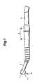
- Fig. 1shows one embodiment of a handpiece of a contra-angle type having a lighting device according to the present invention.
- the handpieceincludes a tool head 1 holding a treatment tool 10, a neck 2 extending from the head 1, a grip 3 detachably connected to the neck 2, and a flexible hose 4 connected to the proximal end of the grip 3.
- the head 1, neck 2, grip 3, and hose 4are assembled in series.
- the grip 3includes two detachable portions; a distal portion 3a and a proximal portion 3b.
- Piping and wiring for compressed air, cooling water, cleaning water, lighting device, and others extending through each of the distal and proximal portions 3a and 3bare connected to each other in an air- and water-tight manner via sealing pipes disposed at respective ends of the portions 3a and 3b. Since the structure of the handpiece except for the lighting device to be discussed later may be conventional, it is not discussed any further.
- the tool head 1has on its lower side (tool attachment side) a lighting device P for illuminating around the tip of the tool 10, in other words, for illuminating a treatment site, substantially without casting a shadow on the site in treatment.
- Fig. 2shows the details of this lighting device P having a plurality of light emitting diodes (LEDs) 7 and an LED holder 5.
- the LEDs 7are encased in an LED holder 5 in the form of an annular groove provided integrally in the lower side of the head 1, and arranged substantially annularly around the tool 10 so as to illuminate the treatment site substantially without casting a shadow on the site in treatment.
- LEDs 7are arranged at regular 90° intervals.
- the number of LEDsare not particularly limited as long as a plurality of LEDs are used and as long as the LEDs can illuminate the treatment site substantially without casting a shadow on the site.
- the arrangement of the LEDsis not particularly limited, but preferably arranged at regular intervals.
- the LEDs 7are connected in series, in parallel, or in series-parallel connection to each other, and also connected to lead wires (not shown) extending through the grip 3 for being supplied with electric power by a treatment unit and the like power supply via the lead wires.
- the LEDs 7are covered with a transparent, heat resistant synthetic resin 8 as shown in Fig. 2 so as not to be exposed to atmosphere.
- the lighting device Pcan withstand repeated sterilization with an autoclave without the LEDs 7 being damaged by the heat experienced during autoclaving.
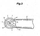
- Fig. 3shows another embodiment of the lighting device of the present invention.
- a lighting device P'similar to the lighting device P, has LEDs 7 encased in an LED holder 5' in the form of a horseshoe groove provided integrally in the lower side of the head 1, and arranged substantially in a horseshoe shape around the tool 10 so as to illuminate the treatment site substantially without casting a shadow on the site in treatment.
- three LEDs 7are arranged at regular 120° intervals.
- This horseshoe LED holder 5'is particularly preferred when the handpiece has on the lower side of the head 1 near the tool 10 an orifice 12 for injecting compressed air, water, and the like.
- the lighting device P'is disposed so that the orifice 12 is placed between the ends of the horseshoe LED holder 5', allowing injection of chip air, washing water, or the like through the orifice 12 toward the treatment site.
- the LEDs 7 in the holder 5'may also be covered with a transparent, heat resistant synthetic resin 8 as in the embodiment of Fig. 2.
- the LED holders 5 and 5'have been described as being integrally formed in the head 1, the LED holder may alternatively be formed as an independent member separate from the head, and mounted on the lower side of the head either fixedly or detachably in a suitable manner. Further, a separate LED holder may be embedded in the annular or horseshoe groove provided in the head 1. The LED holder may be in any form and provided in any manner as long as the LEDs 7 are disposed so as to illuminate the treatment site substantially without casting a shadow on the site in treatment.
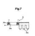
- a lighting device Qhas an LED holder 50 and a clip 60 formed integrally with the holder 50, and is detachably mounted on a handpiece.
- the LED holder 50is in the form of a thin annular container 50a having a through hole 50b in the center thereof, and the LEDs 7 are arranged in the holder 50 at regular 90° intervals as shown in Fig. 6.
- the LED holder 50may be filled with a transparent, heat resistant synthetic resin 8 as shown in Fig. 7. This resin 8 covers the LEDs 7 so as not to expose the LEDs 7 to atmosphere.
- the clip 60has a plurality of pairs of gripping pieces 60a, and may be made of a resilient material such as metals or plastics.
- the clip 60detachably engages with the handpiece near a transition portion between the head 1 and the neck 2 as shown in Fig. 4.
- the clip 60is formed integrally with the holder 50, the clip 60 may be formed as a separate part and attached to the holder 50 in a suitable manner.
- the LED holder 50is placed on the lower side of the head 1 with the tool 10 of the handpiece penetrating through the hole 50b.
- the clip 60engages with the transition portion between the head 1 and the neck 2 to hold the LED holder 50 in place with respect to the head 1.
- the LEDs 7are disposed substantially around the tool 10 to illuminate the treatment site over a range as wide as 360° substantially without casting a shadow on the site in treatment.
- the plurality of LEDs 7are connected either in series, in parallel, or in series-parallel connection, and usually two lead wires or terminals extend out of the LED holder 50, which wires or terminals are connected to a control power supply in the treatment unit via connecting means, such as lead wires, a flexible substrate, connectors, and others. At least a part of such connecting means may pass through the neck 2, grip 3, and flexible hose 4 so as to improve the appearance of the handpiece. It is preferred that the LEDs 7 are supplied with electric power via two driving lines.
- the lead wires or terminals on the side of the LEDs 7may be connected to lead wires or terminals on the side of the control power supply preferably via connectors. More specifically, the LED holder 50 is preferably provided with connector pins fixed to the lead wires or terminals from the LEDs 7, while the connector on the side of the power supply is preferably provided with a socket for receiving the connector pins. Using such connectors, the LED holder 50 may be easily detached from or mounted on the head 1, so that exchange or sterilization of the LED holder 50 may be facilitated.
- the connectorsFor facilitating appropriate orientation of the connectors to match the polarity of the lead wires or terminals on the two connectors, it is preferred that the connectors have complementary concave-convex shapes, or that the wires or terminals on the connectors are not arranged in point symmetrical positions.
- Fig. 8shows another embodiment of the lighting device of the present invention particularly suitable for use with a handpiece having an orifice 12 for injecting chip air and the like.
- the lighting device Q'is similar to the lighting device Q, but has an LED holder 50' in the form of a horseshoe container having a space 11 between the two ends. LEDs 7 are arranged at regular 90° intervals in the LED holder 50'.
- the LED holder 50'can be placed on the lower side of the head 1 without blocking the orifice 12.
- the space 11 between the two ends of the holder 50'is placed over the orifice 12 to allow injection of chip air, washing water, and the like through the orifice 12 toward the treatment site, while the LEDs 7 are arranged around the tool 11 to illuminate the treatment site over a range as wide as 360° substantially without casting a shadow in treatment.
- the LED holder 50'may also be filled with a transparent, heat resistant synthetic resin 8 to cover and protect the LEDs 7.
- the lighting devices Q and Q'have been discussed as having the clip 60, but the clip 60 does not have to be provided. Only the LED holders 50 and 50' may be used as lighting devices, and may be fixedly or detachably mounted on a handpiece in a suitable manner.
- the present inventionhas been discussed particularly with regard to the application to a contra-angle handpiece.
- the present inventionmay also be applied as well to handpieces of straight and other types, and other dental or medical instruments such as air turbines, mirrors, ultrasonic scalers, air scalers, hand scalers, periodontal curets, vacuums, cylinders, and saliva ejectors.
- the lighting device of the present inventionmay be mounted on such instruments in any suitable manner as long as the LED holder is mounted on the distal part of the instrument and the LEDs are arranged so as to illuminate the treatment site substantially without casting a shadow on the site in treatment.
- the lighting deviceemploys as light sources a plurality of LEDs, which consume only a small amount of electric power, so that a portable DC battery or a dry cell may be used as a power supply. Since such battery and cell are readily available and portable, the present invention provides a portable lighting device for use with a dental or medical instrument at low cost.
- the LEDsare arranged so as to illuminate a treatment site substantially without casting a shadow on the site in treatment. Thus, effectiveness in treatment of a site may be improved.
- a dark treatment sitemay be illuminated over a range as wide as 360° so that the effectiveness may further be improved.
- the LEDsmay be supplied with electric power from a power supply via flexible connecting means such as lead wires or flexible substrate, so that installation of the connecting means is facilitated even in a handpiece of a contra-angle type. Further, no problems such as cracking of optical fibers will occur unlike the conventional lighting device having a halogen lamp as a light source and an optical fiber as a light guide. Thus, the lighting device as well as the dental or medical instrument having such lighting device may be manufactured at low cost.
- the LEDs disposed in the LED holdermay be covered with a heat resistant synthetic resin, which protects the LEDs from damage due to heat experienced in autoclaving.
- the lighting device of the present inventionmay be sterilized by autoclaving readily and repeatedly without attenuation of light, and may be used for a prolonged period of time.
- the lighting device of the present inventionmay be detachably mounted on a dental or medical instrument, and the dental or medical instrument of the present invention has the lighting device that may be made detachable.
- the lighting devicemay be easily detached from the instrument for sterilization, or easily exchanged when damaged.
- the detachment of the lighting devicemay further be facilitated.
Landscapes
- Health & Medical Sciences (AREA)
- Oral & Maxillofacial Surgery (AREA)
- Dentistry (AREA)
- Epidemiology (AREA)
- Life Sciences & Earth Sciences (AREA)
- Animal Behavior & Ethology (AREA)
- General Health & Medical Sciences (AREA)
- Public Health (AREA)
- Veterinary Medicine (AREA)
- Dental Tools And Instruments Or Auxiliary Dental Instruments (AREA)
- Endoscopes (AREA)
Abstract
Description
Claims (10)
- A lighting device (P, P', Q, Q') for use with a dental or medical instrumenthaving a tool (10) in a distal part of said instrument for treatment of a site, saidlighting device having a plurality of light emitting diodes (7),
characterized in that said lighting device (P, P', Q, Q') comprises an LEDholder (5, 5', 50, 50') encasing said plurality of light emitting diodes (7) andcapable of being mounted on a distal part of said instrument substantially aroundsaid tool (10),
wherein said LED holder (5, 5', 50', 50') is filled with a transparent, heatresistant synthetic resin suitable for autoclaving, so that said light emitting diodes (7) are covered with saidresin,
wherein said plurality of light emitting diodes (7) are arranged so as to bedisposed substantially around the tool (10), when said LED holder (5, 5', 50, 50') ismounted on said instrument. - The lighting device (P, P', Q, Q') of claim 1, wherein said LED holder (5,5', 50, 50') substantially has a shape selected from the group consisting of anannular shape and a horseshoe shape, and wherein said light emitting diodes (7) arearranged so as to be disposed substantially around said tool (10) when said LEDholder (5, 5', 50, 50') is mounted on said instrument.
- The lighting device (P, P', Q, Q')of claim 2, wherein said light emittingdiodes (7) are arranged substantially at regular intervals.
- The lighting device (P, P', Q, Q') of claim 1 further comprising a clip (60)attached to said LED holder (50, 50'), said clip (60) capable of detachably engagingwith said instrument to detachably hold said LED holder (50, 50') with respect tosaid distal part of said instrument.
- A dental or medical instrument having a tool (10) in a distal part of saidinstrument for treatment of a site; and a lighting device (P, P', Q, Q') having aplurality of light emitting diodes (7),
characterized in that said lighting device (P, P', Q, Q') comprises an LEDholder (5, 5', 50, 50') encasing said plurality of light emitting diodes (7) andprovided in said distal part of said instrument substantially around said tool (10),
wherein said LED holder (5, 5', 50, 50') is filled with a transparent, heatresistant synthetic resin suitable for autoclaving, so that said light emitting diodes (7) are covered with saidresin,
wherein said plurality of light emitting diodes (7) are arranged so as to bedisposed substantially around the tool (10). - The instrument of claim 5, wherein said plurality of light emitting diodes(7) are arranged substantially around said tool (10) substantially in a shape selectedfrom the group consisting of an annular shape and a horseshoe shape.
- The instrument of claim 6, wherein said plurality of light emitting diodes(7) are arranged substantially at regular intervals.
- The instrument of claim 5, wherein said LED holder (5, 5', 50, 50')substantially has a shape selected from the group consisting of an annular shape anda horseshoe shape, and wherein said plurality of light emitting diodes (7) arearranged substantially around said tool (10).
- The instrument of claim 8, wherein said plurality of light emitting diodes(7) are arranged substantially at regular intervals.
- The instrument of claim 5, wherein said lighting device (P, P', Q, Q')further comprises a clip (60) attached to said LED holder (50, 50'), said clip (60)capable of detachably engaging with said instrument to detachably hold said LEDholder (50, 50') with respect to said distal part of said instrument.
Applications Claiming Priority (2)
| Application Number | Priority Date | Filing Date | Title |
|---|---|---|---|
| JP11297899AJP3121812B1 (en) | 1999-10-20 | 1999-10-20 | Lighting equipment for dental and medical instruments |
| JP29789999 | 1999-10-20 |
Publications (4)
| Publication Number | Publication Date |
|---|---|
| EP1093765A2 EP1093765A2 (en) | 2001-04-25 |
| EP1093765A3 EP1093765A3 (en) | 2003-03-12 |
| EP1093765B1true EP1093765B1 (en) | 2005-05-04 |
| EP1093765B2 EP1093765B2 (en) | 2013-04-03 |
Family
ID=17852557
Family Applications (1)
| Application Number | Title | Priority Date | Filing Date |
|---|---|---|---|
| EP00122315AExpired - LifetimeEP1093765B2 (en) | 1999-10-20 | 2000-10-20 | Lighting device for dental or medical instrument |
Country Status (5)
| Country | Link |
|---|---|
| US (1) | US6607384B1 (en) |
| EP (1) | EP1093765B2 (en) |
| JP (1) | JP3121812B1 (en) |
| AT (1) | ATE294542T1 (en) |
| DE (1) | DE60019869T2 (en) |
Cited By (7)
| Publication number | Priority date | Publication date | Assignee | Title |
|---|---|---|---|---|
| US7066733B2 (en) | 1998-01-20 | 2006-06-27 | Kerr Corporation | Apparatus and method for curing materials with light radiation |
| US7182597B2 (en) | 2002-08-08 | 2007-02-27 | Kerr Corporation | Curing light instrument |
| US7540634B2 (en) | 2004-06-15 | 2009-06-02 | Henkel Corporation | High power LED electro-optic assembly |
| US7989839B2 (en) | 2002-08-23 | 2011-08-02 | Koninklijke Philips Electronics, N.V. | Method and apparatus for using light emitting diodes |
| US8096691B2 (en) | 1997-09-25 | 2012-01-17 | Koninklijke Philips Electronics N V | Optical irradiation device |
| US9066777B2 (en) | 2009-04-02 | 2015-06-30 | Kerr Corporation | Curing light device |
| US9726435B2 (en) | 2002-07-25 | 2017-08-08 | Jonathan S. Dahm | Method and apparatus for using light emitting diodes for curing |
Families Citing this family (40)
| Publication number | Priority date | Publication date | Assignee | Title |
|---|---|---|---|---|
| US7294364B2 (en)* | 1999-09-24 | 2007-11-13 | Cao Group, Inc. | Method for curing composite materials |
| AT412526B (en)* | 2002-07-16 | 2005-04-25 | W & H Dentalwerk Buermoos Gmbh | DENTAL HAND OR ANGLE PIECE |
| US7150629B2 (en)* | 2003-03-19 | 2006-12-19 | James Feine | Lighted ultrasonic handpiece and color code grip system |
| KR100800120B1 (en) | 2003-12-08 | 2008-02-01 | 가부시끼가이샤 모리다 세이사꾸쇼 | Dental medical examination device |
| JP4822673B2 (en)* | 2004-04-30 | 2011-11-24 | 株式会社モリタ製作所 | Intraoral lighting device |
| CN100558314C (en)* | 2003-12-08 | 2009-11-11 | 株式会社摩利塔制作所 | Dental diagnosis and treatment device |
| US7074040B2 (en)* | 2004-03-30 | 2006-07-11 | Ultradent Products, Inc. | Ball lens for use with a dental curing light |
| US20050239018A1 (en)* | 2004-04-27 | 2005-10-27 | Scott Green | Intraoral bite spacer and illumination apparatus |
| US20060077671A1 (en)* | 2004-10-13 | 2006-04-13 | Dr. Edelman Dental Clinics Ltd. | Dental illumination device |
| US9877798B2 (en)* | 2005-04-12 | 2018-01-30 | Spring Health Products, Inc. | Electric dental handpiece |
| US7210814B2 (en)* | 2005-04-29 | 2007-05-01 | Ultradent Products, Inc. | Dental curing light with specially arranged LEDs |
| US8459852B2 (en) | 2007-10-05 | 2013-06-11 | Dental Equipment, Llc | LED-based dental exam lamp |
| US7490967B2 (en)* | 2005-06-15 | 2009-02-17 | Philip Syribeys | Solid state light source including cooling system |
| WO2007025636A1 (en)* | 2005-08-27 | 2007-03-08 | Universität Zürich | Illumination device for a dental handpiece, use thereof and method for selective removal of a tooth colored intra-coronal restoration |
| US20070189004A1 (en)* | 2005-12-28 | 2007-08-16 | Guy Dickes | Illum-A-Field Modification of Medical and Surgical Instruments |
| DE102006018143A1 (en)* | 2006-04-19 | 2007-10-25 | Torkzadeh, Masoud, Dr. | Injection syringe for use in medical field particularly medicament application pins, has illuminant having light source, where radiation axis of light source runs parallel to longitudinal axis of injection syringe and to injection needle |
| EP1870022B1 (en)* | 2006-06-22 | 2016-05-11 | W & H Dentalwerk Bürmoos GmbH | Medical handle with a lighting device and method of manufacturing |
| EP1870021B1 (en)* | 2006-06-22 | 2017-05-17 | W & H Dentalwerk Bürmoos GmbH | Medical handpiece with illumination device |
| EP1913864A1 (en)* | 2006-10-15 | 2008-04-23 | Medic.Nrg Ltd. | Illuminator for medical use |
| US20080182222A1 (en)* | 2006-10-20 | 2008-07-31 | Chin-Fu Li | Illuminating device for dental handpieces |
| US7789112B1 (en)* | 2006-11-09 | 2010-09-07 | Wise Robert W | Method and system for inflating an inflatable object |
| US20080166678A1 (en)* | 2007-01-04 | 2008-07-10 | Or Ramot | Removable intraoral lighting device |
| DE102007040596B4 (en) | 2007-08-27 | 2011-01-13 | Epsys Paul Voinea E.K. | Illuminant with heat spread by Wärmeleitbeschichtung |
| US20090130620A1 (en)* | 2007-11-19 | 2009-05-21 | Mohamadreza Yazdi | Bone supported palatal expansion appliance |
| US9072572B2 (en) | 2009-04-02 | 2015-07-07 | Kerr Corporation | Dental light device |
| USD637720S1 (en)* | 2009-07-14 | 2011-05-10 | Karl Storz Gmbh & Co. Kg | Medical instrument |
| USD638944S1 (en) | 2009-09-22 | 2011-05-31 | Ultradent Products, Inc. | Dental illumination device |
| EP2548530B1 (en) | 2011-07-19 | 2014-03-19 | W & H Dentalwerk Bürmoos GmbH | Illuminating device for a medical, in particular dental instrument |
| BRMU9101581Y8 (en)* | 2011-10-26 | 2021-06-22 | Alfredo Holzer Junior | constructive disposition introduced in sucker |
| US20130143175A1 (en)* | 2011-12-02 | 2013-06-06 | Charles F. Betyeman | Illuminated micro-motor hand piece in a veterinary dental device |
| CN103356156A (en)* | 2012-03-26 | 2013-10-23 | 李郁清 | Diagnosis and treatment device that can adjust the range of light |
| US20140349244A1 (en)* | 2013-05-23 | 2014-11-27 | Rakesh Patel | Syringe sleeve |
| EP2842513A1 (en)* | 2013-08-28 | 2015-03-04 | W & H Dentalwerk Bürmoos GmbH | Lighting device for a medical, in particular dental instrument |
| EP3064166B1 (en) | 2015-03-06 | 2018-07-04 | Schott AG | Hermetically sealed led light, and method for manufacturing a hermetically sealed led light |
| DE102015103402B4 (en) | 2015-03-09 | 2017-07-27 | Ferton Holding S.A. | Optical component, lighting device and handpiece of a dental treatment device |
| CN104842833A (en)* | 2015-05-27 | 2015-08-19 | 李寒玉 | Split type safety headrest of seat of automobile |
| AU2019277665B2 (en) | 2018-06-01 | 2025-04-17 | Stryker Corporation | Surgical handpiece including a visible light emitter and a system and method for determining an identity of a surgical handpiece |
| CN113396487B (en)* | 2019-02-04 | 2024-12-03 | 松下知识产权经营株式会社 | Light-emitting device and medical device using the same |
| EP3744288A1 (en)* | 2019-05-29 | 2020-12-02 | DENTSPLY SIRONA Inc. | Illuminating instrument for diagnostics, surgery or therapy |
| CN220348268U (en) | 2020-02-24 | 2024-01-16 | 米沃奇电动工具公司 | Impact tool and rotary power tool |
Family Cites Families (21)
| Publication number | Priority date | Publication date | Assignee | Title |
|---|---|---|---|---|
| US2588288A (en)† | 1948-02-24 | 1952-03-04 | Pohanka Joseph | Dental light |
| US3109238A (en)* | 1961-11-28 | 1963-11-05 | Samuel B Marks | Portable dental drill |
| DE1466959A1 (en)* | 1965-04-02 | 1969-02-20 | Borchers Dr Med Dent Helmut | Device for illuminating the work area during dental treatments |
| US3590232A (en)* | 1968-03-27 | 1971-06-29 | Radioptics Inc | Annular illuminator for dental tools or the like |
| JPS53129491A (en)† | 1977-04-18 | 1978-11-11 | Tetsuo Nomoto | Handpiece |
| US4230453A (en)† | 1979-04-11 | 1980-10-28 | Litton Industrial Products Inc. | Light assembly for use with a dental handpiece |
| JPS5873170A (en)† | 1981-10-27 | 1983-05-02 | Fujitsu Ltd | semiconductor light emitting device |
| JPS58168311A (en) | 1982-03-30 | 1983-10-04 | Toshiba Corp | Combination emitter follower circuit |
| GB2132378B (en)† | 1982-11-19 | 1986-05-21 | Gwyndann Group | Illumination of optical instruments |
| IL74405A0 (en)† | 1985-02-21 | 1985-05-31 | Moshe Meller | Illuminated dental drill |
| US5458486A (en)* | 1992-03-17 | 1995-10-17 | Ballard; Stephen L. | Dental mirror apparatus |
| DE4232644A1 (en)† | 1992-09-29 | 1994-03-31 | Siemens Ag | Opto-electronic semiconductor element for LED, photodiode etc. - is enclosed in plastics, with semiconductor chip, associated head conductive strips, and centring element between them |
| JP3443158B2 (en) | 1994-04-11 | 2003-09-02 | 株式会社モリタ製作所 | Dental syringe with built-in lighting device |
| US5741132A (en)* | 1996-03-13 | 1998-04-21 | Usui Kokusai Sangyo Kaisha Ltd. | Mirror for dental examination |
| EP0846915B1 (en)† | 1996-12-04 | 2003-08-27 | Siteco Beleuchtungstechnik GmbH | Inner room light |
| JPH10337292A (en)* | 1997-06-09 | 1998-12-22 | Nakanishi:Kk | Dental hand piece |
| JP3782220B2 (en) | 1997-09-30 | 2006-06-07 | 株式会社モリタ製作所 | Laser medical device and its handpiece |
| IT1296088B1 (en)* | 1997-11-10 | 1999-06-09 | Mectron Di Bianchetti Fernando | DENTAL HANDPIECE WITH BUILT-IN LIGHT SOURCE |
| IT1296089B1 (en)† | 1997-11-10 | 1999-06-09 | Mectron Di Bianchetti Fernando | DENTAL HANDPIECE WITH LIGHT SOURCE FOR DIAGNOSTIC PURPOSE |
| JPH11202164A (en) | 1998-01-19 | 1999-07-30 | Toyoda Gosei Co Ltd | Optical source module |
| EP0941691A1 (en)* | 1998-03-11 | 1999-09-15 | Welch Allyn, Inc. | Compact video imaging assembly |
- 1999
- 1999-10-20JPJP11297899Apatent/JP3121812B1/ennot_activeExpired - Lifetime
- 2000
- 2000-10-19USUS09/691,998patent/US6607384B1/ennot_activeExpired - Lifetime
- 2000-10-20EPEP00122315Apatent/EP1093765B2/ennot_activeExpired - Lifetime
- 2000-10-20ATAT00122315Tpatent/ATE294542T1/enactive
- 2000-10-20DEDE60019869Tpatent/DE60019869T2/ennot_activeExpired - Lifetime
Cited By (8)
| Publication number | Priority date | Publication date | Assignee | Title |
|---|---|---|---|---|
| US8096691B2 (en) | 1997-09-25 | 2012-01-17 | Koninklijke Philips Electronics N V | Optical irradiation device |
| US7066733B2 (en) | 1998-01-20 | 2006-06-27 | Kerr Corporation | Apparatus and method for curing materials with light radiation |
| US7210930B2 (en) | 1998-01-20 | 2007-05-01 | Kerr Corporation | Apparatus and method for curing materials with radiation |
| US9726435B2 (en) | 2002-07-25 | 2017-08-08 | Jonathan S. Dahm | Method and apparatus for using light emitting diodes for curing |
| US7182597B2 (en) | 2002-08-08 | 2007-02-27 | Kerr Corporation | Curing light instrument |
| US7989839B2 (en) | 2002-08-23 | 2011-08-02 | Koninklijke Philips Electronics, N.V. | Method and apparatus for using light emitting diodes |
| US7540634B2 (en) | 2004-06-15 | 2009-06-02 | Henkel Corporation | High power LED electro-optic assembly |
| US9066777B2 (en) | 2009-04-02 | 2015-06-30 | Kerr Corporation | Curing light device |
Also Published As
| Publication number | Publication date |
|---|---|
| ATE294542T1 (en) | 2005-05-15 |
| DE60019869D1 (en) | 2005-06-09 |
| EP1093765A2 (en) | 2001-04-25 |
| JP3121812B1 (en) | 2001-01-09 |
| JP2001112779A (en) | 2001-04-24 |
| EP1093765B2 (en) | 2013-04-03 |
| EP1093765A3 (en) | 2003-03-12 |
| US6607384B1 (en) | 2003-08-19 |
| DE60019869T2 (en) | 2006-01-19 |
Similar Documents
| Publication | Publication Date | Title |
|---|---|---|
| EP1093765B1 (en) | Lighting device for dental or medical instrument | |
| US9259143B2 (en) | Illuminated dental retractor | |
| EP0884025B1 (en) | Dental handpiece with lighting means | |
| US7150629B2 (en) | Lighted ultrasonic handpiece and color code grip system | |
| US7611256B2 (en) | Illuminator for medical use | |
| US20080113312A1 (en) | Device for unilateral or bilateral illumination of oral cavity | |
| US20050239018A1 (en) | Intraoral bite spacer and illumination apparatus | |
| ITMI972501A1 (en) | DENTAL HANDPIECE WITH BUILT-IN LIGHT SOURCE | |
| JP2000316874A (en) | Dental instrument with lighting | |
| CA2324331A1 (en) | Illuminated suction tool with a disposable tip | |
| US20250099217A1 (en) | Electric toothbrush | |
| US20060269898A1 (en) | Inside Mouth Dental Light | |
| CA3094628A1 (en) | Work light | |
| JP2005177143A (en) | Connector apparatus and intrabuccal suction unit | |
| RU177538U1 (en) | DENTAL EXHAUSTING TOOL WITH DISPOSABLE TIP WITH LOCAL LIGHTING | |
| JP7607390B2 (en) | Oral suction device | |
| JP2002028133A (en) | Dental mirror | |
| CN213607089U (en) | Light-guiding flushing type mouth-protecting toothbrush | |
| KR101233040B1 (en) | Dental LED UNIT For Mouth Prop | |
| KR200409740Y1 (en) | Removable lighting device for dental surgical equipment | |
| MX2009012827A (en) | Intraoral illumination system. | |
| RU36964U1 (en) | DENTAL TIP | |
| CN117157031A (en) | intraoral suction device | |
| TW200924694A (en) | Oral illuminator | |
| KR20060075340A (en) | Dental mirror |
Legal Events
| Date | Code | Title | Description |
|---|---|---|---|
| PUAI | Public reference made under article 153(3) epc to a published international application that has entered the european phase | Free format text:ORIGINAL CODE: 0009012 | |
| AK | Designated contracting states | Kind code of ref document:A2 Designated state(s):AT BE CH CY DE DK ES FI FR GB GR IE IT LI LU MC NL PT SE | |
| AX | Request for extension of the european patent | Free format text:AL;LT;LV;MK;RO;SI | |
| PUAL | Search report despatched | Free format text:ORIGINAL CODE: 0009013 | |
| AK | Designated contracting states | Kind code of ref document:A3 Designated state(s):AT BE CH CY DE DK ES FI FR GB GR IE IT LI LU MC NL PT SE | |
| AX | Request for extension of the european patent | Extension state:AL LT LV MK RO SI | |
| RIC1 | Information provided on ipc code assigned before grant | Ipc:7A 61C 1/08 A Ipc:7A 61B 1/247 B Ipc:7F 21V 21/088 B | |
| 17P | Request for examination filed | Effective date:20030905 | |
| AKX | Designation fees paid | Designated state(s):AT CH DE FR GB IT LI | |
| 17Q | First examination report despatched | Effective date:20031121 | |
| GRAP | Despatch of communication of intention to grant a patent | Free format text:ORIGINAL CODE: EPIDOSNIGR1 | |
| GRAS | Grant fee paid | Free format text:ORIGINAL CODE: EPIDOSNIGR3 | |
| GRAA | (expected) grant | Free format text:ORIGINAL CODE: 0009210 | |
| RAP1 | Party data changed (applicant data changed or rights of an application transferred) | Owner name:NAKANISHI INC. | |
| RIN1 | Information on inventor provided before grant (corrected) | Inventor name:NAKANISHI, KENSUKE | |
| AK | Designated contracting states | Kind code of ref document:B1 Designated state(s):AT CH DE FR GB IT LI | |
| REG | Reference to a national code | Ref country code:GB Ref legal event code:FG4D | |
| REG | Reference to a national code | Ref country code:CH Ref legal event code:EP | |
| REG | Reference to a national code | Ref country code:IE Ref legal event code:FG4D | |
| REF | Corresponds to: | Ref document number:60019869 Country of ref document:DE Date of ref document:20050609 Kind code of ref document:P | |
| REG | Reference to a national code | Ref country code:CH Ref legal event code:NV Representative=s name:KATZAROV S.A. | |
| PLBI | Opposition filed | Free format text:ORIGINAL CODE: 0009260 | |
| PLAX | Notice of opposition and request to file observation + time limit sent | Free format text:ORIGINAL CODE: EPIDOSNOBS2 | |
| 26 | Opposition filed | Opponent name:W&H DENTALWERK BUERMOOS GMBH Effective date:20060203 | |
| ET | Fr: translation filed | ||
| PLBB | Reply of patent proprietor to notice(s) of opposition received | Free format text:ORIGINAL CODE: EPIDOSNOBS3 | |
| RDAF | Communication despatched that patent is revoked | Free format text:ORIGINAL CODE: EPIDOSNREV1 | |
| APBP | Date of receipt of notice of appeal recorded | Free format text:ORIGINAL CODE: EPIDOSNNOA2O | |
| APAH | Appeal reference modified | Free format text:ORIGINAL CODE: EPIDOSCREFNO | |
| APBQ | Date of receipt of statement of grounds of appeal recorded | Free format text:ORIGINAL CODE: EPIDOSNNOA3O | |
| PLAB | Opposition data, opponent's data or that of the opponent's representative modified | Free format text:ORIGINAL CODE: 0009299OPPO | |
| PLBP | Opposition withdrawn | Free format text:ORIGINAL CODE: 0009264 | |
| APAH | Appeal reference modified | Free format text:ORIGINAL CODE: EPIDOSCREFNO | |
| APBU | Appeal procedure closed | Free format text:ORIGINAL CODE: EPIDOSNNOA9O | |
| PUAH | Patent maintained in amended form | Free format text:ORIGINAL CODE: 0009272 | |
| STAA | Information on the status of an ep patent application or granted ep patent | Free format text:STATUS: PATENT MAINTAINED AS AMENDED | |
| 27A | Patent maintained in amended form | Effective date:20130403 | |
| AK | Designated contracting states | Kind code of ref document:B2 Designated state(s):AT CH DE FR GB IT LI | |
| REG | Reference to a national code | Ref country code:CH Ref legal event code:AELC | |
| REG | Reference to a national code | Ref country code:DE Ref legal event code:R102 Ref document number:60019869 Country of ref document:DE Effective date:20130403 | |
| REG | Reference to a national code | Ref country code:FR Ref legal event code:PLFP Year of fee payment:17 | |
| REG | Reference to a national code | Ref country code:FR Ref legal event code:PLFP Year of fee payment:18 | |
| REG | Reference to a national code | Ref country code:CH Ref legal event code:PCAR Free format text:NEW ADDRESS: AVENUE DES MORGINES 12, 1213 PETIT-LANCY (CH) | |
| REG | Reference to a national code | Ref country code:FR Ref legal event code:PLFP Year of fee payment:19 | |
| PGFP | Annual fee paid to national office [announced via postgrant information from national office to epo] | Ref country code:FR Payment date:20190913 Year of fee payment:20 | |
| PGFP | Annual fee paid to national office [announced via postgrant information from national office to epo] | Ref country code:DE Payment date:20191008 Year of fee payment:20 | |
| PGFP | Annual fee paid to national office [announced via postgrant information from national office to epo] | Ref country code:IT Payment date:20191009 Year of fee payment:20 | |
| PGFP | Annual fee paid to national office [announced via postgrant information from national office to epo] | Ref country code:CH Payment date:20191015 Year of fee payment:20 Ref country code:AT Payment date:20190925 Year of fee payment:20 | |
| PGFP | Annual fee paid to national office [announced via postgrant information from national office to epo] | Ref country code:GB Payment date:20191018 Year of fee payment:20 | |
| REG | Reference to a national code | Ref country code:DE Ref legal event code:R071 Ref document number:60019869 Country of ref document:DE | |
| REG | Reference to a national code | Ref country code:CH Ref legal event code:PL | |
| REG | Reference to a national code | Ref country code:GB Ref legal event code:PE20 Expiry date:20201019 | |
| REG | Reference to a national code | Ref country code:AT Ref legal event code:MK07 Ref document number:294542 Country of ref document:AT Kind code of ref document:T Effective date:20201020 | |
| PG25 | Lapsed in a contracting state [announced via postgrant information from national office to epo] | Ref country code:GB Free format text:LAPSE BECAUSE OF EXPIRATION OF PROTECTION Effective date:20201019 |