EP1093757B1 - Device for collection of soft tissue - Google Patents
Device for collection of soft tissueDownload PDFInfo
- Publication number
- EP1093757B1 EP1093757B1EP00309123AEP00309123AEP1093757B1EP 1093757 B1EP1093757 B1EP 1093757B1EP 00309123 AEP00309123 AEP 00309123AEP 00309123 AEP00309123 AEP 00309123AEP 1093757 B1EP1093757 B1EP 1093757B1
- Authority
- EP
- European Patent Office
- Prior art keywords
- tissue
- distal end
- eyelet
- tubular body
- distal
- Prior art date
- Legal status (The legal status is an assumption and is not a legal conclusion. Google has not performed a legal analysis and makes no representation as to the accuracy of the status listed.)
- Expired - Lifetime
Links
- 210000004872soft tissueAnatomy0.000titledescription3
- 239000000523sampleSubstances0.000claimsdescription60
- 238000005520cutting processMethods0.000claimsdescription29
- 238000005070samplingMethods0.000claimsdescription15
- 230000003902lesionEffects0.000claimsdescription10
- 229910000639Spring steelInorganic materials0.000claimsdescription2
- 239000000463materialSubstances0.000claimsdescription2
- 210000001519tissueAnatomy0.000description65
- 238000001574biopsyMethods0.000description28
- 238000000034methodMethods0.000description22
- 210000001165lymph nodeAnatomy0.000description21
- 206010006187Breast cancerDiseases0.000description12
- 208000026310Breast neoplasmDiseases0.000description12
- 210000005005sentinel lymph nodeAnatomy0.000description12
- 210000004027cellAnatomy0.000description8
- 230000009471actionEffects0.000description7
- 210000000481breastAnatomy0.000description7
- 206010028980NeoplasmDiseases0.000description6
- 210000001099axillaAnatomy0.000description6
- 230000001926lymphatic effectEffects0.000description5
- 238000010276constructionMethods0.000description4
- 238000011161developmentMethods0.000description4
- 230000007246mechanismEffects0.000description4
- 201000009030CarcinomaDiseases0.000description3
- 206010025282LymphoedemaDiseases0.000description3
- 201000011510cancerDiseases0.000description3
- 230000006835compressionEffects0.000description3
- 238000007906compressionMethods0.000description3
- 238000003745diagnosisMethods0.000description3
- 238000003384imaging methodMethods0.000description3
- 208000002502lymphedemaDiseases0.000description3
- 206010061289metastatic neoplasmDiseases0.000description3
- 230000008569processEffects0.000description3
- 238000001356surgical procedureMethods0.000description3
- 238000002604ultrasonographyMethods0.000description3
- 210000004204blood vesselAnatomy0.000description2
- 239000002131composite materialSubstances0.000description2
- 230000000881depressing effectEffects0.000description2
- 208000037265diseases, disorders, signs and symptomsDiseases0.000description2
- 238000003780insertionMethods0.000description2
- 230000037431insertionEffects0.000description2
- 230000003447ipsilateral effectEffects0.000description2
- 210000005036nerveAnatomy0.000description2
- 230000003534oscillatory effectEffects0.000description2
- 230000002441reversible effectEffects0.000description2
- 238000012216screeningMethods0.000description2
- 238000009121systemic therapyMethods0.000description2
- 238000012360testing methodMethods0.000description2
- 230000002792vascularEffects0.000description2
- 206010055113Breast cancer metastaticDiseases0.000description1
- 208000009458Carcinoma in SituDiseases0.000description1
- 241001465754MetazoaSpecies0.000description1
- 208000006994Precancerous ConditionsDiseases0.000description1
- NINIDFKCEFEMDL-UHFFFAOYSA-NSulfurChemical compound[S]NINIDFKCEFEMDL-UHFFFAOYSA-N0.000description1
- 230000002159abnormal effectEffects0.000description1
- 230000005856abnormalityEffects0.000description1
- 230000003213activating effectEffects0.000description1
- 210000000577adipose tissueAnatomy0.000description1
- 238000007486appendectomyMethods0.000description1
- 238000013459approachMethods0.000description1
- 210000001367arteryAnatomy0.000description1
- 210000004369bloodAnatomy0.000description1
- 239000008280bloodSubstances0.000description1
- 239000001045blue dyeSubstances0.000description1
- 230000008859changeEffects0.000description1
- 238000002512chemotherapyMethods0.000description1
- 239000000084colloidal systemSubstances0.000description1
- 230000000994depressogenic effectEffects0.000description1
- 238000001514detection methodMethods0.000description1
- 201000010099diseaseDiseases0.000description1
- 208000035475disorderDiseases0.000description1
- 238000006073displacement reactionMethods0.000description1
- 238000002224dissectionMethods0.000description1
- 239000000975dyeSubstances0.000description1
- 230000000694effectsEffects0.000description1
- 238000007387excisional biopsyMethods0.000description1
- 239000012634fragmentSubstances0.000description1
- 239000011521glassSubstances0.000description1
- 230000012010growthEffects0.000description1
- 230000002962histologic effectEffects0.000description1
- 206010020718hyperplasiaDiseases0.000description1
- 201000004933in situ carcinomaDiseases0.000description1
- 238000007386incisional biopsyMethods0.000description1
- 238000002347injectionMethods0.000description1
- 239000007924injectionSubstances0.000description1
- 238000012977invasive surgical procedureMethods0.000description1
- 238000002955isolationMethods0.000description1
- 210000004185liverAnatomy0.000description1
- 230000004807localizationEffects0.000description1
- 210000004324lymphatic systemAnatomy0.000description1
- 230000003211malignant effectEffects0.000description1
- 210000005075mammary glandAnatomy0.000description1
- 238000009607mammographyMethods0.000description1
- 239000003550markerSubstances0.000description1
- 239000011159matrix materialSubstances0.000description1
- 229940127554medical productDrugs0.000description1
- 201000001441melanomaDiseases0.000description1
- 230000001394metastastic effectEffects0.000description1
- 239000008267milkSubstances0.000description1
- 210000004080milkAnatomy0.000description1
- 239000002991molded plasticSubstances0.000description1
- 238000013059nephrectomyMethods0.000description1
- 238000002355open surgical procedureMethods0.000description1
- 210000000056organAnatomy0.000description1
- 239000012188paraffin waxSubstances0.000description1
- 230000007170pathologyEffects0.000description1
- 238000012545processingMethods0.000description1
- 230000005855radiationEffects0.000description1
- 230000002285radioactive effectEffects0.000description1
- 238000011084recoveryMethods0.000description1
- 230000003578releasing effectEffects0.000description1
- 230000000717retained effectEffects0.000description1
- 238000010911splenectomyMethods0.000description1
- 229910001220stainless steelInorganic materials0.000description1
- 239000010935stainless steelSubstances0.000description1
- 229910052717sulfurInorganic materials0.000description1
- 239000011593sulfurSubstances0.000description1
- 210000000115thoracic cavityAnatomy0.000description1
- 230000032258transportEffects0.000description1
- 210000003462veinAnatomy0.000description1
Images


Classifications
- A—HUMAN NECESSITIES
- A61—MEDICAL OR VETERINARY SCIENCE; HYGIENE
- A61B—DIAGNOSIS; SURGERY; IDENTIFICATION
- A61B10/00—Instruments for taking body samples for diagnostic purposes; Other methods or instruments for diagnosis, e.g. for vaccination diagnosis, sex determination or ovulation-period determination; Throat striking implements
- A61B10/02—Instruments for taking cell samples or for biopsy
- A61B10/0233—Pointed or sharp biopsy instruments
- A61B10/0266—Pointed or sharp biopsy instruments means for severing sample
- A—HUMAN NECESSITIES
- A61—MEDICAL OR VETERINARY SCIENCE; HYGIENE
- A61B—DIAGNOSIS; SURGERY; IDENTIFICATION
- A61B10/00—Instruments for taking body samples for diagnostic purposes; Other methods or instruments for diagnosis, e.g. for vaccination diagnosis, sex determination or ovulation-period determination; Throat striking implements
- A61B10/02—Instruments for taking cell samples or for biopsy
- A61B10/0233—Pointed or sharp biopsy instruments
- A61B10/0283—Pointed or sharp biopsy instruments with vacuum aspiration, e.g. caused by retractable plunger or by connected syringe
- A—HUMAN NECESSITIES
- A61—MEDICAL OR VETERINARY SCIENCE; HYGIENE
- A61B—DIAGNOSIS; SURGERY; IDENTIFICATION
- A61B17/00—Surgical instruments, devices or methods
- A61B17/32—Surgical cutting instruments
- A61B17/320016—Endoscopic cutting instruments, e.g. arthroscopes, resectoscopes
- A61B2017/32004—Endoscopic cutting instruments, e.g. arthroscopes, resectoscopes having a laterally movable cutting member at its most distal end which remains within the contours of said end
- A—HUMAN NECESSITIES
- A61—MEDICAL OR VETERINARY SCIENCE; HYGIENE
- A61B—DIAGNOSIS; SURGERY; IDENTIFICATION
- A61B90/00—Instruments, implements or accessories specially adapted for surgery or diagnosis and not covered by any of the groups A61B1/00 - A61B50/00, e.g. for luxation treatment or for protecting wound edges
- A61B90/06—Measuring instruments not otherwise provided for
- A61B2090/062—Measuring instruments not otherwise provided for penetration depth
- A—HUMAN NECESSITIES
- A61—MEDICAL OR VETERINARY SCIENCE; HYGIENE
- A61B—DIAGNOSIS; SURGERY; IDENTIFICATION
- A61B90/00—Instruments, implements or accessories specially adapted for surgery or diagnosis and not covered by any of the groups A61B1/00 - A61B50/00, e.g. for luxation treatment or for protecting wound edges
- A61B90/36—Image-producing devices or illumination devices not otherwise provided for
- A61B90/37—Surgical systems with images on a monitor during operation
- A61B2090/378—Surgical systems with images on a monitor during operation using ultrasound
Definitions
- the present inventionrelates to devices for tissue sampling, and more specifically to improved instruments for acquiring soft body tissue.
- biopsymay be done by an open or percutaneous technique. Open biopsy, which is an invasive surgical procedure using a scalpel and involving direct vision of the target area, removes the entire mass (excisional biopsy) or a part of the mass (incisional biopsy).
- Percutaneous biopsyis usually done with a needle-like instrument through a relatively small incision, blindly or with the aid of an artificial imaging device, and may be either a fine needle aspiration (FNA) or a core biopsy.
- FNA biopsyindividual cells or clusters of cells are obtained for cytologic examination and may be prepared such as in a Papanicolaou smear.
- core biopsyas the term suggests, a core or fragment of tissue is obtained for histologic examination which may be done via a frozen section or paraffin section.
- biopsyThe type of biopsy utilized depends in large part on circumstances present with respect to the patient, including the location of the lesion(s) within the body, and no single procedure is ideal for all cases. However, core biopsy is extremely useful in a number of conditions and is being used more frequently by the medical profession.
- a very successful type of image guided percutaneous core breast biopsy instrument currently availableis a vacuum-assisted automatic core biopsy device.
- One such successful biopsy deviceis shown and disclosed in U.S. Patent No. 5,526,822, U.S. Patent No. 5,649,547, and U.S. Patent No. 5,769,086, all of which are commonly owned by the assignee of the present application.
- This deviceknown commercially as the MAMMOTOME® Biopsy System, has the capability to actively capture tissue prior to cutting the tissue. Active capture allows for sampling through non-homogeneous tissues, meaning that the device is equally capable of cutting through hard and soft tissue.
- the deviceis comprised of a disposable probe, a motorized drive unit, and an integrated vacuum source.
- the probeis made of stainless steel and molded plastic and is designed for collection of multiple tissue samples with a single insertion of the probe into the breast.
- the tip of the probeis configured with a laterally disposed sampling notch for capturing tissue samples. Orientation of the sample notch is directed by the physician, who uses a thumbwheel to direct tissue sampling in any direction about the circumference of the probe.
- a hollow cylindrical cuttersevers and transports tissue samples to a tissue collection chamber for later testing.
- a core biopsy deviceof a type disclosed in U.S. Patent No. 5,111,828, to Kornberg et al., wherein the tissue receiving port is disposed at the distal end of the device and is oriented axially rather than laterally.
- a disadvantage of this type of deviceis the lack of ability to effectively and efficiently draw tissue into the receiving chamber prior to and during the tissue cutting process.
- a second disadvantageis the requirement to withdraw the device from parent tissue and remove the first specimen, reassemble the device, then reintroduce the device for each desired specimen.
- a third disadvantageis the necessity of manually handling each specimen obtained.
- the ability to sample any selected area of a cavity wall from within the cavitymay be important, which ability requires the use of a flexible probe.
- breast cancerstarts in the milk ducts, the mammary glands.
- the initial change towards breast canceris now thought to be the development of atypical ductile hyperplasia.
- the next stepis thought to be represented by ductile carcinoma in situ.
- the last step in the development of breast canceris infiltrating ductile carcinoma.
- breast cancer cellshave developed the ability to migrate from the duct of origin, disassociate themselves from one another, and enter vascular structures, such as the lymphatic channels. When these malignant infiltrative ductile carcinoma cells enter the vascular system, they can spread or metastasize to other parts of the body. It is this metastatic process that ultimately leads to death from breast cancer.
- breast cancer cellsWhen breast cancer cells enter the lymphatic system, they metastasize in an orderly fashion to regional lymph nodes. Drainage can occur to the axillary lymph nodes, the supraclavicular lymph nodes, the lateral thoracic lymph nodes, and to the internal mammary lymph nodes.
- lymphadenectomyIt is the current standard of practice to determine if breast cancer cells have extended to regional lymph nodes by surgically performing an axillary lymph node dissection known as lymphadenectomy. In this open surgical procedure, a relatively large incision (5-10 cm), is made at the axilla (the armpit). Through this incision, a relatively large volume (15 to 30 grams) of fatty tissue and lymph node tissue are removed.
- lymph nodescan be recovered and submitted to pathology, where each of these lymph nodes is examined for the presence or absence of metastatic breast cancer. Based on positive lymph node findings, systemic therapy will be given to the patient with breast cancer, including chemotherapy. If, on the other hand, the lymph nodes of the axilla are free of metastatic disease, then the use of systemic therapies is limited.
- Surgical lymphadenectomycarries a low mortality, but high morbidity.
- the most common morbidityis the development of lymph edema in the arm, which is ipsilateral to the axilla dissected.
- the development of lymph edema in the ipsilateral armis, at times, a debilitating complication.
- lymphatic drainage patternscan be defined by the injection of a radioisotope (or other traceable marker such as blue dye) into the bed of the tumor.
- the isotope (or dye)is then followed, either visually, with a gamma camera imaging system, or with a Geiger counter-type of counting system.
- the first lymph node in the draining systemis referred to as the "sentinel" lymph node.
- the elements of a percutaneous sentinel lymph node biopsyare as follows: The tumor site in the breast is injected with a radioisotope (such as technicium 99m labeled sulfur colloid) which travels via the lymphatic channels to the sentinel lymph node. The sentinel lymph node then becomes radioactively visible, or "hot.”
- the apparatus hereafter describedis able to identify or locate the radioactive lymph node through auditory and other signals, indicating when the apparatus is adjacent to the sentinel lymph node.
- the apparatusis further able to then characterize or "visualize" the surrounding tissue with the associated ultrasound portion of the apparatus. It is important to identify the associated structures adjacent to the lymph node, because relatively large blood vessels (arteries, veins,) and nerves traverse the axilla. With the combination of percutaneous Geiger counter identification and percutaneous ultrasound identification, the sentinel lymph node can be identified and biopsied without entering a major blood vessel or severing a major nerve.
- U.S. Patent No. 5,111,828 to Kornberg et al.discloses a percutaneous excisional breast biopsy device having a cannula, open distal and proximal ends, and a sharp cutting surface on the distal end.
- a styletextends through the cannula and includes a distal puncturing end.
- a localization guide wireis used to direct the instrument to a biopsy site. The cannula is moved distally to cut a desired tissue specimen, after which a descending element is pushed to the distal end of the tissue specimen, then pulled proximally to sever the specimen completely from surrounding tissue.
- a significant disadvantage of the Kornberg approachis that only one tissue sample may be obtained for each insertion of the instrument into the patient's body to the biopsy site. Once the descending element has been pulled to sever the tissue sample, there is no opportunity to repeat the procedure while the instrument remains in place. Also, no means is provided to ensure that tissue to be sampled is drawn toward the distal end of the cannula 2 (or “actively captured”), thereby reducing tissue sampling efficiency.
- a tissue sampling apparatusis also disclosed in US 5 857 982.
- the features of the present invention known from US 5 857 982have been placed in the preamble of claim 1, appended hereto.
- the present inventionlacks the disadvantages and shortcomings of the prior art and provides an improved device for percutaneous excisional tissue biopsy.
- the present inventionmay be used for purposes others than percutaneous biopsy.
- the devicemay be used for general organ and tissue removal through a trocar to perform various laparascopic procedures including splenectomy, nephrectomy, appendectomy and liver removal.
- the devicemay also be used laparascopically through a trocar to remove abnormal growths such as polyps.
- the inventionprovides an inventive tissue sampling apparatus according to claim 1. It offers many advantages over probes available in the prior art. Unexpectedly superior results are obtained in connection with the retrieval of intact tissue specimens, because of a unique combination of cutting features. A particularly important feature of the invention is the ability to manipulate the cutting element to cleanly sever the distal end of the tissue specimen. In the preferred embodiments, this is accomplished without any cutting impact on surrounding tissue.
- the versatility of the inventionpermits its use in many applications, including, for example, breast biopsies, intraoperative staging, lapatascopic surgery, and lymphadenectomy procedures.
- a tissue sampling apparatuswhich comprises a tubular body having a primary lumen for receiving a tissue sample.
- the tubular bodyincludes a distal end, a proximal end, and a longitudinal axis extending from the proximal end to the distal end.
- the tissue sampling apparatusfurther comprises a cutting cylinder having a distal cutting edge, which is movable both distally and proximally relative to the tubular body.
- a band having an eyelet disposed thereinextends across a distal end of the tissue sampling apparatus, the eyelet being advantageously movable relative to the distal cutting edge in order to sever a distal end of the tissue sample.
- the inventive tissue sampling probe 10comprises a cylindrical outer sheath 12, and a lumen 14, which extends through the entire length of the probe 10.
- the outer sheath 12preferably comprises a biocompatible composite material such as a glass filament wound, epoxy-impregnated matrix material, for example, and preferably has a round cross-section, though other shapes may be used as well.
- a biocompatible composite materialsuch as a glass filament wound, epoxy-impregnated matrix material, for example, and preferably has a round cross-section, though other shapes may be used as well.
- Advantageous characteristics of the preferred composite materialinclude light weight, durability, and ductility.
- an actuator 16Disposed proximally of the outer sheath 12 is an actuator 16, which preferably comprises a housing 18, a fixed handle 20, a trigger 22, and a motor trigger 24.
- an internal cylindrical cutter 25Disposed within the lumen 14, and extending along the length thereof, is an internal cylindrical cutter 25.
- the cutter 25is selectively driven rotationally by means of a cable drive 26, which transfers rotational energy from an external motor or other power supply (not shown) through a drive gear 28 and a cutter gear 30 (Figs. 15, 17, and 19).
- a cable drive 26which transfers rotational energy from an external motor or other power supply (not shown) through a drive gear 28 and a cutter gear 30 (Figs. 15, 17, and 19).
- an internal motor disposed within the housing 18could be provided.
- the motor trigger 24actuates the cable drive to drive the gears 28 and 30, thereby selectively rotating the cutter 25, for a purpose to be described more fully hereinbelow.
- a cage 32surrounding the cutter gear 30.
- a rail 34Extending distally from the cage 32 is a rail 34, which is preferably constructed to be integral with the cage 32.
- the railextends distally through a stop plate 36.
- a main carriage 38is slidably disposed on the rail 34.
- a lever 40is disposed in the fixed handle 20, the lever having a camming surface 42 which engages a camming portion 44 of the trigger 22.
- the camming portion 44 of the triggeris pivotably mounted on a pivot pin 45 (Figs. 15, 17, 19).
- an actuator portion 46Integral with, or, alternatively, engageable with an inboard end of the lever 40 is an actuator portion 46 which includes a distal portion having a longitudinal slot 48.
- the slot 48slidably engages a pin 50 which is disposed on a distal carriage 52.
- the distal carriage 52like the main carriage 38, is slidable along the rail 34.
- an eyelet pin 54Distally of the distal carriage 52 is an eyelet pin 54, which is attached to one end of a flexible eyelet band 56.
- the flexible eyelet band 56is preferably constructed of spring steel or other similar material.
- Disposed about the band 56 and internal cutter cylinder 25is a compression spring 58, wherein the eyelet pin 54 is captured between the proximal end of the compression spring 58 and a fixed plate 59.
- the band 56extends distally through the lumen 14 between the cutter cylinder 25 and the outer sheath 12.
- the probe 10preferably comprises a shaped distal portion 62 having substantially flat surfaces 64 along which the eyelet band 56 may be disposed.
- the eyelet band 56wraps about the distal end of the probe 10, as best seen in Fig. 8, and extends proximally again back along the distal portion 62 and then beneath the outer sheath 12.
- the band 56is secured at its second end to the main carriage 38, using a pin attachment (not shown) similar to that obtained at its first end by means of pin 54, or other suitable fixed attachment means.
- a lesion 66 within the tissue 68 of a patientis identified for removal by a physician.
- the instrument 10is positioned outside of the patient's body at a point proximal to the target lesion 66.
- the probe 10is advanced distally into the tissue 68, as illustrated in Fig. 10.
- the distal business end of the instrument 10 at this point in time, with the cutter 25 in an extended position,is illustrated in Fig. 4, while the configuration of the trigger and internal trigger mechanism during the acquisition step of Figs. 10 and 4 is shown in Figs. 14 and 15.
- the motor trigger 24is depressed by the practitioner, to thereby actuate the motor and cause rotation of the cutter 25 by means of drive gear 28 and cutter gear 30.
- the advancement of the probe 10easily slices through the tissue to create a tissue specimen 70 (Fig. 10) for capture within the lumen 14.
- depth marksmay be disposed axially along the exterior surface of the sheath 12 in order to assist the physician in determining when the instrument 10 has been advanced to the desired position.
- the probe 10functions to define and cut a tissue sample 70 having approximately the same diameter or cross-sectional shape as that of the lumen 14. Once a sample of adequate length has been secured, and the target lesion is fully contained within the lumen 14, advancement of the probe 10 is halted. At this point, the motor trigger 24 may be released to de-activate the motor, and thereby stop rotation of the cutter 25. Alternatively, depending upon the nature of a particular procedure, the practitioner may selectively actuate and stop the operation of the motor, as desired, during the balance of the procedure.
- a skin incisionmay be made in the patient's tissue 68 to form a pocket into which the probe 10 may be inserted.
- a vacuum source(not shown), attached to the lumen 14 through a vacuum fitting 72, may be activated to draw a vacuum through the lumen 14, thereby drawing the desired tissue sample, including the lesion 66, into the lumen 14.
- the inventive instrumentadvantageously is designed to be used in connection with sensing probes for identifying and locating desired tissue (i.e. sentinel nodes) to be sampled.
- sensing probesfor identifying and locating desired tissue (i.e. sentinel nodes) to be sampled.
- ultrasound probes or radiation detecting (Geiger) probesmay be employed, such as those disclosed in U.S. Patent Nos. 4,959,547, 5,036,201, 5,119,818, 5,148,040, 5,170,055, and 5,246,005, which are assigned to Care Wise Medical Products Corporation of Morgan Hill, California.
- a probe fitting 74is employed, which has an aperture 76 therein for direct connection with the lumen 14, from the proximal end 78 to the distal end of the instrument 10.
- the probe fitting 74is configured to receive a sensing probe 80 (Figs. 9-13).
- a stand alone sensing probe 80 for use with the inventive instrumentmay comprise either an ultrasonic probe or a Geiger probe, both of which are conventionally known in the medical diagnostic arts.
- the sensing probe 80is specifically configured to be inserted through the aperture 76 of the soft tissue acquisition device 10.
- Electronic control linesextend from the proximal end of the sensing probe 80 to appropriate control units, for receiving and processing information obtained by the probe.
- a multi-vision probemay be utilized.
- This type of sensing probeis capable of functioning both as an ultrasonic probe and as a Geiger probe, and has two sets of control lines for communicating with ultrasonic and Geiger electronic control units, respectively.
- the lesion 66is located using the sensing probe, rather than the aforementioned imaging guidance equipment.
- the Geiger portion of the probeprovides an X-Y location on the surface of the tissue to be sampled, while the ultrasonic portion provides depth information as well as X-Y location information.
- the sensing probe 80may be retained in the lumen 14 during the acquisition procedure, in which case it can function as a tissue stop for the tissue sample being captured in the lumen 14, as shown in Figs. 10-13.
- the cutting cylinder 25is retracted, as shown in Figs. 11, 5, 16, and 17, by partially depressing the trigger 22 (Figs. 16 and 17).
- This actioncauses the camming portion 44 of the trigger to pivot about the pivot pin 45 so that the camming surface of the lever 40 moves responsive to the pivoting of the camming portion 44 to exert a proximal pulling force on the pin 50 by its engagement with the longitudinal slot 48 on the actuator portion 46.
- the pin 50extends from the distal carriage 52, the proximal movement of the pin 50 also causes the distal carriage 52 to be displaced proximally. This proximal displacement of the distal carriage 52 is illustrated in Fig. 17, relative to Fig. 15. As shown, in Fig.
- the distal carriagehas moved sufficiently proximally so that it is engaged with the main carriage 38, but not sufficiently to push the main carriage proximally. Because the cutter 25 is attached to the distal carriage 52, the proximal movement of the distal carriage 52 causes the cutter 25 to be retracted proximally, as shown in Fig. 5.
- the flexible eyelet band 56includes an eyelet aperture 82 which ordinarily surrounds the extended cylindrical cutter 25 at the distal end of the instrument 10, as shown in Fig. 4. However, once the cutter has been retracted, as shown in Fig. 5, by the method above discussed, the band 56 is free to slide around the shaped distal portion 62 along the substantially flat surfaces 64, so that the eyelet bunches the distal end of the captured tissue specimen 70 and causes severance of the specimen distal end by the bunching action of the eyelet 82 of the tissue against the cutting surface of the cutter 25. The practitioner moves the eyelet band 56 as described, in order to sever the distal end of the tissue sample, by depressing the trigger fully, as shown in Figs. 18 and 19.
- one or more additional samplesmay be obtained and accommodated within the lumen if desired.
- the triggeris partially released so that the compression spring 58 will expand to bias the eyelet pin 54 proximally, thereby returning the flexible band 56 and eyelet 82 to their initial positions as shown in Fig. 5.
- the triggeris released the remainder of the way to again extend the cutting cylinder 25 distally, as shown in Fig. 4.
- the entire proceduremay be repeated to obtain additional samples as desired, or until the lumen has reached its capacity.
- the instrumentmay be removed from the patient's body so that the tissue sample(s) may be extracted and examined.
- the interior surface of the lumen 14may be coated to reduce frictional contact between the lumen walls and the tissue sample as it travels therethrough.
- a modified embodimentis illustrated in Figs. 20-24, wherein all elements corresponding to those of the embodiment of Figure 1 are designated by like reference numerals, succeeded by the letter "a".
- a cam nut 84is provided on the actuator portion 16a, which is rotatable to a first position in order to initiate a camming action which retracts the cutting cylinder 25a, and to a second position in order to initiate a further camming action which moves the eyelet band 56a.
- the trigger 24aoperates the motor, but because of its construction, the practitioner has an ability to alternately squeeze and release the trigger 24a to create an oscillatory circular cutting action of the cylindrical cutter 25a.
- This oscillatory cutting actioncan be created by alternately activating and de-activating the motor, to cause the rotation of the cutter 25a to be alternately started and stopped, or the motor can be reversible, so that the alternate squeezing and releasing action of the practitioner actually causes the rotational direction of the cylinder to reverse.
Landscapes
- Health & Medical Sciences (AREA)
- Life Sciences & Earth Sciences (AREA)
- Medical Informatics (AREA)
- Engineering & Computer Science (AREA)
- Biomedical Technology (AREA)
- Heart & Thoracic Surgery (AREA)
- Pathology (AREA)
- Molecular Biology (AREA)
- Surgery (AREA)
- Animal Behavior & Ethology (AREA)
- General Health & Medical Sciences (AREA)
- Public Health (AREA)
- Veterinary Medicine (AREA)
- Surgical Instruments (AREA)
- Sampling And Sample Adjustment (AREA)
Description
- The present invention relates to devices for tissue sampling, andmore specifically to improved instruments for acquiring soft body tissue.
- It is often desirable and frequently necessary to sample or test a portion of tissuefrom humans and other animals, particularly in the diagnosis and treatment of patientswith cancerous tumors, pre-malignant conditions, and other diseases or disorders.
- Typically, in the case of breast cancer, there is a great emphasis on early detectionand diagnosis through the use of screening modalities, such as physical examination, andparticularly mammography, which is capable of detecting very small abnormalities, oftennonpalpable. When the physician establishes by means of a mammogram or otherscreening modality that suspicious circumstances exist, a biopsy must be performed tocapture tissue for a definitive diagnosis as to whether the suspicious lesion is cancerous.Biopsy may be done by an open or percutaneous technique. Open biopsy, which is aninvasive surgical procedure using a scalpel and involving direct vision of the target area,removes the entire mass (excisional biopsy) or a part of the mass (incisional biopsy).Percutaneous biopsy, on the other hand, is usually done with a needle-like instrumentthrough a relatively small incision, blindly or with the aid of an artificial imaging device,and may be either a fine needle aspiration (FNA) or a core biopsy. In FNA biopsy,individual cells or clusters of cells are obtained for cytologic examination and may beprepared such as in a Papanicolaou smear. In core biopsy, as the term suggests, a core orfragment of tissue is obtained for histologic examination which may be done via a frozen section or paraffin section.
- The type of biopsy utilized depends in large part on circumstances present withrespect to the patient, including the location of the lesion(s) within the body, and nosingle procedure is ideal for all cases. However, core biopsy is extremely useful in anumber of conditions and is being used more frequently by the medical profession.
- A very successful type of image guided percutaneous core breast biopsyinstrument currently available is a vacuum-assisted automatic core biopsy device. Onesuch successful biopsy device is shown and disclosed in U.S. Patent No. 5,526,822, U.S.Patent No. 5,649,547, and U.S. Patent No. 5,769,086, all of which are commonly ownedby the assignee of the present application.This device, known commercially as the MAMMOTOME® Biopsy System,has the capability to actively capture tissue prior to cutting the tissue. Active captureallows for sampling through non-homogeneous tissues, meaning that the device isequally capable of cutting through hard and soft tissue. The device is comprised of adisposable probe, a motorized drive unit, and an integrated vacuum source. The probe ismade of stainless steel and molded plastic and is designed for collection of multipletissue samples with a single insertion of the probe into the breast. The tip of the probe isconfigured with a laterally disposed sampling notch for capturing tissue samples.Orientation of the sample notch is directed by the physician, who uses a thumbwheel todirect tissue sampling in any direction about the circumference of the probe. A hollowcylindrical cutter severs and transports tissue samples to a tissue collection chamber forlater testing.
- While the MAMMOTOME Biopsy System functions very well as a core biopsydevice, there are occasions when, because of the size of a lesion, or its location, it may beadvantageous to use a core biopsy device of a type disclosed in U.S. Patent No.5,111,828, to Kornberg et al., whereinthe tissue receiving port is disposed at the distal end of the device and is oriented axiallyrather than laterally. A disadvantage of this type of device, however, is the lack of ability to effectively and efficiently draw tissue into the receiving chamber prior to and duringthe tissue cutting process. A second disadvantage is the requirement to withdraw thedevice from parent tissue and remove the first specimen, reassemble the device, thenreintroduce the device for each desired specimen. A third disadvantage is the necessityof manually handling each specimen obtained.
- On other occasions, the ability to sample any selected area of a cavity wall fromwithin the cavity may be important, which ability requires the use of a flexible probe.
- Furthermore, it is desirable during the biopsy process to "stage" the spread of acancer. For example, breast cancer starts in the milk ducts, the mammary glands. Theinitial change towards breast cancer is now thought to be the development of atypicalductile hyperplasia. The next step is thought to be represented by ductile carcinoma insitu. Finally, the last step in the development of breast cancer is infiltrating ductilecarcinoma. By the time the breast cancer has reached the stage of infiltrative ductilecarcinoma, breast cancer cells have developed the ability to migrate from the duct oforigin, disassociate themselves from one another, and enter vascular structures, such asthe lymphatic channels. When these malignant infiltrative ductile carcinoma cells enterthe vascular system, they can spread or metastasize to other parts of the body. It is thismetastatic process that ultimately leads to death from breast cancer.
- When breast cancer cells enter the lymphatic system, they metastasize in anorderly fashion to regional lymph nodes. Drainage can occur to the axillary lymphnodes, the supraclavicular lymph nodes, the lateral thoracic lymph nodes, and to theinternal mammary lymph nodes.
- It is the current standard of practice to determine if breast cancer cells haveextended to regional lymph nodes by surgically performing an axillary lymph nodedissection known as lymphadenectomy. In this open surgical procedure, a relativelylarge incision (5-10 cm), is made at the axilla (the armpit). Through this incision, arelatively large volume (15 to 30 grams) of fatty tissue and lymph node tissue areremoved.
- During this process, anywhere from 10 to 30 lymph nodes can be recovered andsubmitted to pathology, where each of these lymph nodes is examined for the presence orabsence of metastatic breast cancer. Based on positive lymph node findings, systemictherapy will be given to the patient with breast cancer, including chemotherapy. If, onthe other hand, the lymph nodes of the axilla are free of metastatic disease, then the useof systemic therapies is limited.
- Surgical lymphadenectomy carries a low mortality, but high morbidity. The mostcommon morbidity is the development of lymph edema in the arm, which is ipsilateral tothe axilla dissected. The development of lymph edema in the ipsilateral arm is, at times,a debilitating complication.
- It has been shown in the examination of lymphatic drainage of melanoma, andnow shown in the lymphatic drainage of breast cancers, that lymphatic drainage patternscan be defined by the injection of a radioisotope (or other traceable marker such as bluedye) into the bed of the tumor. The isotope (or dye) is then followed, either visually,with a gamma camera imaging system, or with a Geiger counter-type of counting system.
- The spread of cancer cells is orderly, the first lymph node reached by the drainagechannels from the infected breast containing the most cancer cells. Consequently, thefirst lymph node in the draining system is referred to as the "sentinel" lymph node.
- It has been further shown, if one simply removes the sentinel lymph node, thedetermination of whether or not breast cancer has metastasized to the regional lymphnodes of the axilla can be established without excision of the remaining lymph nodes inthe axilla. The surgical removal of only one lymph node greatly reduces thecomplications of lymph node surgery including the morbidity of lymph edema.
- It would be desirable to further reduce the morbidity of the axillary sentinellymph node biopsy if instrumentation were available to allow the sentinel lymph node tobe identified and removed percutaneously with as little effect as possible to thesurrounding tissue structure. The apparatus described in this patent can be introducedpercutaneously through a small skin opening and directed to the sentinel lymph node thus eliminating open surgical exploration. Consequently, sentinel lymph node biopsycould be accomplished as an office procedure, eliminating hospitalization andminimizing the recovery period.
- The elements of a percutaneous sentinel lymph node biopsy are as follows: Thetumor site in the breast is injected with a radioisotope (such as technicium 99m labeledsulfur colloid) which travels via the lymphatic channels to the sentinel lymph node. Thesentinel lymph node then becomes radioactively visible, or "hot." The apparatushereafter described is able to identify or locate the radioactive lymph node throughauditory and other signals, indicating when the apparatus is adjacent to the sentinellymph node. The apparatus is further able to then characterize or "visualize" thesurrounding tissue with the associated ultrasound portion of the apparatus. It isimportant to identify the associated structures adjacent to the lymph node, becauserelatively large blood vessels (arteries, veins,) and nerves traverse the axilla. With thecombination of percutaneous Geiger counter identification and percutaneous ultrasoundidentification, the sentinel lymph node can be identified and biopsied without entering amajor blood vessel or severing a major nerve.
- With a small entry site, no suturing would be required (the procedure would bepercutaneous), and the patient could be sent home with a simple band-aid over theaxillary entry site. The following day, the patient would receive the results of thepercutaneous sentinel lymph node biopsy determining whether or not metastatic diseaseis present or absent in the sentinel lymph node draining the affected breast.
- Instruments are known in the prior art which could be adapted to perform someof the procedures outlined above. For example, U.S. Patent No. 5,111,828 to Kornberget al. discloses a percutaneous excisional breast biopsy device having a cannula, opendistal and proximal ends, and a sharp cutting surface on the distal end. A stylet extendsthrough the cannula and includes a distal puncturing end. A localization guide wire isused to direct the instrument to a biopsy site. The cannula is moved distally to cut adesired tissue specimen, after which a descending element is pushed to the distal end of the tissue specimen, then pulled proximally to sever the specimen completely fromsurrounding tissue.
- A significant disadvantage of the Kornberg approach is that only one tissuesample may be obtained for each insertion of the instrument into the patient's body to thebiopsy site. Once the descending element has been pulled to sever the tissue sample,there is no opportunity to repeat the procedure while the instrument remains in place.Also, no means is provided to ensure that tissue to be sampled is drawn toward the distalend of the cannula 2 (or "actively captured"), thereby reducing tissue samplingefficiency.
- A tissue sampling apparatus is also disclosed in US 5 857 982. The featuresof the present invention known from US 5 857 982 have been placed in the preamble of claim 1, appended hereto.
- The present invention lacks the disadvantages and shortcomings of the prior artand provides an improved device for percutaneous excisional tissue biopsy.The present invention may be used for purposes others than percutaneous biopsy. Forexample, the device may be used for general organ and tissue removal through a trocar toperform various laparascopic procedures including splenectomy, nephrectomy,appendectomy and liver removal. The device may also be used laparascopically througha trocar to remove abnormal growths such as polyps.
- More particularly, the invention provides an inventive tissue sampling apparatus according toclaim 1. It offers many advantages over probes available in the prior art. Unexpectedlysuperior results are obtained in connection with the retrieval of intact tissue specimens,because of a unique combination of cutting features. A particularly important feature ofthe invention is the ability to manipulate the cutting element to cleanly sever the distalend of the tissue specimen. In the preferred embodiments, this is accomplished withoutany cutting impact on surrounding tissue. The versatility of the invention permits its usein many applications, including, for example, breast biopsies, intraoperative staging,lapatascopic surgery, and lymphadenectomy procedures.
- More particularly, in one aspect of the invention, there is provided a tissuesampling apparatus which comprises a tubular body having a primary lumen forreceiving a tissue sample. The tubular body includes a distal end, a proximal end, and alongitudinal axis extending from the proximal end to the distal end. The tissue samplingapparatus further comprises a cutting cylinder having a distal cutting edge, which ismovable both distally and proximally relative to the tubular body. A band having aneyelet disposed therein extends across a distal end of the tissue sampling apparatus, theeyelet being advantageously movable relative to the distal cutting edge in order to sever adistal end of the tissue sample.
- The invention, together with additional features and advantages thereof, may bestbe understood by reference to the following description taken in conjunction with theaccompanying illustrative drawing.
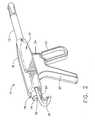
- Fig. 1 is a perspective view of a first preferred embodiment of the inventive tissuesampling instrument;
- Fig. 2 is a perspective view, from an opposing side, of the inventive instrumentshown in Fig. 1;
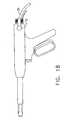
- Fig. 3 is a perspective view similar to Fig. 1, with portions of the instrumenthousing removed to illustrate the internal construction of the inventive instrument;'
- Figs. 4-8 are perspective views of the distal end of the inventive instrumentshown in Fig. 1, shown in isolation, illustrating sequentially the relative position of theeyelet cutter during a representative tissue specimen capturing procedure;
- Figs. 9-13 are schematic side views of the distal end of the inventive instrumentshown in Fig. 1, illustrating sequentially the operation of the inventive eyelet cutterduring a typical tissue capture procedure;
- Fig. 14 is a schematic side view of the inventive instrument shown in Fig. 1,illustrating the instrument and the position of the trigger when the distal business end ofthe cutting instrument is in its initial position as shown in Fig.4;
- Fig. 15 is a cross-sectional view illustrating the internal working mechanism ofthe inventive instrument when the distal business end of the cutting instrument is in itsinitial position as shown in Fig. 4;
- Fig. 16 is a schematic side view of the inventive instrument shown in Fig. 1, illustrating the instrument and the position of the trigger when the internal cylinder hasbeen proximally retracted as shown in Fig. 5;
- Fig. 17 is a cross-sectional view illustrating the internal working mechanism ofthe inventive instrument when the distal business end of the cutting instrument is in theconfiguration shown in Fig. 5;
- Fig. 18 is a schematic side view of the inventive instrument shown in Fig. 1,illustrating the instrument and the position of the trigger when the internal cylinder hasbeen proximally retracted and the eyelet cutter has been actuated to rotate about the distalend of the instrument as shown in Figs. 7 and 8;
- Fig. 19 is a cross-sectional view illustrating the internal working mechanism ofthe inventive instrument when the distal business end of the cutting instrument is in theconfiguration shown in Figs 7 and 8.
- Fig. 20 is a schematic plan view from the side of a second modified embodimentof the inventive tissue sampling instrument;
- Fig. 21 is a perspective view of the inventive instrument illustrated in Fig. 20;
- Fig. 22 is a cross-sectional side view illustrating the internal construction of theinventive instrument illustrated in Figs. 20 and 21;
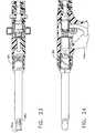
- Fig. 23 is a cross-sectional top view of the inventive instrument illustrated inFigs. 20-22; and
- Fig. 24 is a cross-sectional fragmentary side view of the inventive instrument illustrated in Figs. 20-23.
- Referring now more particularly to Figs. 1-3, a first preferred embodiment of theinvention is shown. The inventive
tissue sampling probe 10 comprises a cylindricalouter sheath 12, and alumen 14, which extends through the entire length of theprobe 10. - The
outer sheath 12 preferably comprises a biocompatible composite materialsuch as a glass filament wound, epoxy-impregnated matrix material, for example, andpreferably has a round cross-section, though other shapes may be used as well.Advantageous characteristics of the preferred composite material include light weight,durability, and ductility. - Disposed proximally of the
outer sheath 12 is anactuator 16, which preferablycomprises ahousing 18, a fixedhandle 20, atrigger 22, and amotor trigger 24.Disposed within thelumen 14, and extending along the length thereof, is an internalcylindrical cutter 25. In the illustrated preferred embodiment, thecutter 25 is selectivelydriven rotationally by means of acable drive 26, which transfers rotational energy froman external motor or other power supply (not shown) through adrive gear 28 and a cuttergear 30 (Figs. 15, 17, and 19). Alternatively, an internal motor disposed within thehousing 18 could be provided. Themotor trigger 24 actuates the cable drive to drive thegears cutter 25, for a purpose to be describedmore fully hereinbelow. - Further with particular reference to Figs. 3, 15, 17, and 19, which illustrate theinternal construction of the
inventive instrument 10, there is shown acage 32surrounding thecutter gear 30. Extending distally from thecage 32 is arail 34, which ispreferably constructed to be integral with thecage 32. The rail extends distally through astop plate 36. Amain carriage 38 is slidably disposed on therail 34. Alever 40 isdisposed in the fixedhandle 20, the lever having acamming surface 42 which engages a camming portion 44 of thetrigger 22. The camming portion 44 of the trigger ispivotably mounted on a pivot pin 45 (Figs. 15, 17, 19). Integral with, or, alternatively,engageable with an inboard end of thelever 40 is anactuator portion 46 which includes adistal portion having alongitudinal slot 48. Theslot 48 slidably engages apin 50 whichis disposed on adistal carriage 52. Thedistal carriage 52, like themain carriage 38, isslidable along therail 34. - Distally of the
distal carriage 52 is aneyelet pin 54, which is attached to one endof aflexible eyelet band 56. Theflexible eyelet band 56 is preferably constructed ofspring steel or other similar material. Disposed about theband 56 andinternal cuttercylinder 25 is acompression spring 58, wherein theeyelet pin 54 is captured between theproximal end of thecompression spring 58 and a fixedplate 59. Theband 56 extendsdistally through thelumen 14 between thecutter cylinder 25 and theouter sheath 12.Distally of thedistal edge 60 of theouter sheath 12, theprobe 10 preferably comprises ashapeddistal portion 62 having substantiallyflat surfaces 64 along which theeyelet band 56 may be disposed. Theeyelet band 56 wraps about the distal end of theprobe 10, asbest seen in Fig. 8, and extends proximally again back along thedistal portion 62 andthen beneath theouter sheath 12. Theband 56 is secured at its second end to themaincarriage 38, using a pin attachment (not shown) similar to that obtained at its first end bymeans ofpin 54, or other suitable fixed attachment means. - Now with particular reference to Figs.9-13, the operation of the
inventive probe 10 will be described. Initially, as shown in Fig. 9, alesion 66 within thetissue 68 of apatient is identified for removal by a physician. Accordingly, again as shown in Fig. 9,using known image guidance techniques, theinstrument 10 is positioned outside of thepatient's body at a point proximal to thetarget lesion 66. Then, with thecutter 25extended, theprobe 10 is advanced distally into thetissue 68, as illustrated in Fig. 10.The distal business end of theinstrument 10 at this point in time, with thecutter 25 in anextended position, is illustrated in Fig. 4, while the configuration of the trigger andinternal trigger mechanism during the acquisition step of Figs. 10 and 4 is shown in Figs. 14 and 15. - Simultaneously with advancement of the
instrument 10, themotor trigger 24 isdepressed by the practitioner, to thereby actuate the motor and cause rotation of thecutter 25 by means ofdrive gear 28 andcutter gear 30. With the cutter rotating, theadvancement of theprobe 10 easily slices through the tissue to create a tissue specimen70 (Fig. 10) for capture within thelumen 14. In the preferred embodiment, depth marks(not shown) may be disposed axially along the exterior surface of thesheath 12 in orderto assist the physician in determining when theinstrument 10 has been advanced to thedesired position. - In its preferred operational mode, the
probe 10 functions to define and cut atissuesample 70 having approximately the same diameter or cross-sectional shape as that of thelumen 14. Once a sample of adequate length has been secured, and the target lesion isfully contained within thelumen 14, advancement of theprobe 10 is halted. At thispoint, themotor trigger 24 may be released to de-activate the motor, and thereby stoprotation of thecutter 25. Alternatively, depending upon the nature of a particularprocedure, the practitioner may selectively actuate and stop the operation of the motor, asdesired, during the balance of the procedure. - If desired, as an alternative to physical advancement of the
probe 10 into thepatient's body, as above described, a skin incision may be made in the patient'stissue 68to form a pocket into which theprobe 10 may be inserted. Then, a vacuum source (notshown), attached to thelumen 14 through a vacuum fitting 72, may be activated to drawa vacuum through thelumen 14, thereby drawing the desired tissue sample, including thelesion 66, into thelumen 14. - As discussed supra, in the Background of the Invention portion of thespecification, a particularly useful purpose for the invention is to identify and targetsentinel nodes for biopsy. Accordingly, the inventive instrument advantageously isdesigned to be used in connection with sensing probes for identifying and locatingdesired tissue (i.e. sentinel nodes) to be sampled. For example, ultrasound probes or radiation detecting (Geiger) probes may be employed, such as those disclosed in U.S.Patent Nos. 4,959,547, 5,036,201, 5,119,818, 5,148,040, 5,170,055, and 5,246,005,which are assigned to Care Wise Medical Products Corporation of Morgan Hill,California. Referring particularlynow to Fig. 2, a probe fitting 74 is employed, which has an
aperture 76 therein for directconnection with thelumen 14, from theproximal end 78 to the distal end of theinstrument 10. The probe fitting 74 is configured to receive a sensing probe 80 (Figs. 9-13). - A stand alone sensing
probe 80 for use with the inventive instrument maycomprise either an ultrasonic probe or a Geiger probe, both of which are conventionallyknown in the medical diagnostic arts. Thesensing probe 80 is specifically configured tobe inserted through theaperture 76 of the softtissue acquisition device 10. Electroniccontrol lines (not shown) extend from the proximal end of thesensing probe 80 toappropriate control units, for receiving and processing information obtained by theprobe. - Alternatively, a multi-vision probe may be utilized. This type of sensing probe iscapable of functioning both as an ultrasonic probe and as a Geiger probe, and has twosets of control lines for communicating with ultrasonic and Geiger electronic controlunits, respectively.
- In operation, if a
sensing probe 80 is utilized, thelesion 66 is located using thesensing probe, rather than the aforementioned imaging guidance equipment. The Geigerportion of the probe provides an X-Y location on the surface of the tissue to be sampled,while the ultrasonic portion provides depth information as well as X-Y locationinformation. Thesensing probe 80 may be retained in thelumen 14 during theacquisition procedure, in which case it can function as a tissue stop for the tissue samplebeing captured in thelumen 14, as shown in Figs. 10-13. - Once the tissue specimen has been captured within the
lumen 14, the cuttingcylinder 25 is retracted, as shown in Figs. 11, 5, 16, and 17, by partially depressing the trigger 22 (Figs. 16 and 17). This action causes the camming portion 44 of the trigger topivot about thepivot pin 45 so that the camming surface of thelever 40 movesresponsive to the pivoting of the camming portion 44 to exert a proximal pulling force onthepin 50 by its engagement with thelongitudinal slot 48 on theactuator portion 46.Since thepin 50 extends from thedistal carriage 52, the proximal movement of thepin 50 also causes thedistal carriage 52 to be displaced proximally. This proximaldisplacement of thedistal carriage 52 is illustrated in Fig. 17, relative to Fig. 15. Asshown, in Fig. 17, the distal carriage has moved sufficiently proximally so that it isengaged with themain carriage 38, but not sufficiently to push the main carriageproximally. Because thecutter 25 is attached to thedistal carriage 52, the proximalmovement of thedistal carriage 52 causes thecutter 25 to be retracted proximally, asshown in Fig. 5. - The
flexible eyelet band 56 includes aneyelet aperture 82 which ordinarilysurrounds the extendedcylindrical cutter 25 at the distal end of theinstrument 10, asshown in Fig. 4. However, once the cutter has been retracted, as shown in Fig. 5, by themethod above discussed, theband 56 is free to slide around the shapeddistal portion 62along the substantiallyflat surfaces 64, so that the eyelet bunches the distal end of thecapturedtissue specimen 70 and causes severance of the specimen distal end by thebunching action of theeyelet 82 of the tissue against the cutting surface of thecutter 25.The practitioner moves theeyelet band 56 as described, in order to sever the distal end ofthe tissue sample, by depressing the trigger fully, as shown in Figs. 18 and 19. Thisaction causes thedistal carriage 52 to fully engage themain carriage 38 and to push itproximally, as shown in Fig. 19. As the main carriage moves proximally, theband 56 ispulled downwardly around thedistal portion 62 of theinstrument 10, as sequentiallyshown in Figs. 6-8, so that theeyelet 82 moves downwardly around the edge andproximally for a predetermined distance along the lower surface of the shapeddistalportion 62. By the time theeyelet 82 has fully moved past thelumen 14 andcutter 25,the distal end of thetissue specimen 70 will have been fully severed, so that the desiredtissue specimen 70 including thetarget lesion 66 will have been fully captured within thelumen 14. - Once this procedure has been completed, one or more additional samples may beobtained and accommodated within the lumen if desired. To do so, the trigger ispartially released so that the
compression spring 58 will expand to bias theeyelet pin 54proximally, thereby returning theflexible band 56 andeyelet 82 to their initial positionsas shown in Fig. 5. Then, the trigger is released the remainder of the way to again extendthe cuttingcylinder 25 distally, as shown in Fig. 4. At this juncture the entire proceduremay be repeated to obtain additional samples as desired, or until the lumen has reachedits capacity. When the desired tissue samples have been obtained, the instrument may beremoved from the patient's body so that the tissue sample(s) may be extracted andexamined. In order to expedite tissue sample capture, the interior surface of thelumen 14 may be coated to reduce frictional contact between the lumen walls and the tissuesample as it travels therethrough. - Many other embodiments may be employed other than the embodimentillustrated in Fig. 1. For example, a modified embodiment is illustrated in Figs. 20-24,wherein all elements corresponding to those of the embodiment of Figure 1 aredesignated by like reference numerals, succeeded by the letter "a". In this embodiment, a
cam nut 84 is provided on theactuator portion 16a, which is rotatable to a first positionin order to initiate a camming action which retracts thecutting cylinder 25a, and to asecond position in order to initiate a further camming action which moves theeyeletband 56a. In this embodiment, thetrigger 24a operates the motor, but because of itsconstruction, the practitioner has an ability to alternately squeeze and release thetrigger 24a to create an oscillatory circular cutting action of thecylindrical cutter 25a. Thisoscillatory cutting action can be created by alternately activating and de-activating themotor, to cause the rotation of thecutter 25a to be alternately started and stopped, or themotor can be reversible, so that the alternate squeezing and releasing action of thepractitioner actually causes the rotational direction of the cylinder to reverse. - While this invention has been described with respect to various specific examplesand embodiments, it is to be understood that the invention is not limited thereto. Forexample, further embodiments could be developed which employed selected features ofeach of the embodiments disclosed herein. Additionally, in some circumstances, it maybe desirable to construct the inventive device so that portions thereof which are exposedto a patient's blood and tissue during a procedure, such as the cutting cylinder and eyeletportions, and perhaps the entire tubular body, are disposable, and may be removablefrom the reusable actuator portion between procedures, for replacement with a newsterile cutting portion. Thus, it is clear that the disclosed invention can be variouslypracticed within the scope of the following claims.
Claims (10)
- A tissue sampling apparatus (10), comprising:a tubular body (12) having a primary lumen (14) for receiving a tissue sample, and having adistal end, a proximal end, and a longitudinal axis extending from said proximal end tosaid distal end;a cutting cylinder (25) having a distal cutting edge and being movable both distally andproximally relative to said tubular body (12); anda band;
characterised by:the band (56) having an eyelet (82) disposed therein and extending across a distal end of saidtissue sampling apparatus (10), said eyelet (82) being movable relative to said distal cutting edge inorder to sever a distal end of said tissue sample. - The apparatus (10) of Claim 1, wherein said tubular body comprises an outer sheath (12),and said cutting cylinder (25) is disposed coaxially within said outer sheath (12).
- The apparatus (10) of Claim 1 or Claim 2, wherein said cutting cylinder (25) is selectivelyrotatable.
- The apparatus (10) of any one of Claims 1 to 3, and further comprising an actuator (16)disposed proximally of said tubular body (12).
- The apparatus (10) of Claim 4, wherein said actuator (16) is adapted to move said band (56) inorder to move said eyelet (82) relative to said tubular body (12).
- The apparatus (10) of Claim 5, wherein said actuator (16) comprises a trigger (22).
- The apparatus (10) of any one of Claims 1 to 6, further comprising a sensing probedisposed therein for identifying and locating a target lesion prior to actuating saidapparatus (10).
- The apparatus (10) of any one of Claims 1 to 7, for use in capturing a body tissuesample by: advancing the tubular body (12) through a tissue portion a desired distance so thatthe cutting element (25) cuts a tissue sample core as the tissue sample enters the lumen; andactuating the eyelet (82) to move across the distal end of the tubular body (12) to sever a distal endof the tissue sample core.
- The apparatus (10) of any one of the preceding Claims, wherein theeyelet (82) ordinarily surrounds the distally moved cutting cylinder (25) at thedistal end of the apparatus (10).
- The apparatus of any one of the preceding Claims, wherein theband (56) is made of spring steel or other simular material.
Applications Claiming Priority (2)
| Application Number | Priority Date | Filing Date | Title |
|---|---|---|---|
| US420339 | 1999-10-18 | ||
| US09/420,339US6280398B1 (en) | 1999-10-18 | 1999-10-18 | Methods and devices for collection of soft tissue |
Publications (2)
| Publication Number | Publication Date |
|---|---|
| EP1093757A1 EP1093757A1 (en) | 2001-04-25 |
| EP1093757B1true EP1093757B1 (en) | 2005-12-07 |
Family
ID=23666068
Family Applications (1)
| Application Number | Title | Priority Date | Filing Date |
|---|---|---|---|
| EP00309123AExpired - LifetimeEP1093757B1 (en) | 1999-10-18 | 2000-10-17 | Device for collection of soft tissue |
Country Status (4)
| Country | Link |
|---|---|
| US (2) | US6280398B1 (en) |
| EP (1) | EP1093757B1 (en) |
| DE (1) | DE60024562T2 (en) |
| ES (1) | ES2253189T3 (en) |
Families Citing this family (76)
| Publication number | Priority date | Publication date | Assignee | Title |
|---|---|---|---|---|
| ITCE990004A1 (en)* | 1999-10-25 | 2000-01-25 | Mario Immacolato Paternuosto | VALVE FOR BIOPSY FORCEPS IN DIGESTIVE ENDOSCOPY |
| US6346085B1 (en)* | 2000-06-27 | 2002-02-12 | Noah I. Schiffman | Soft tissue biopsy instrument |
| US20030050648A1 (en) | 2001-09-11 | 2003-03-13 | Spiration, Inc. | Removable lung reduction devices, systems, and methods |
| US6592594B2 (en) | 2001-10-25 | 2003-07-15 | Spiration, Inc. | Bronchial obstruction device deployment system and method |
| US20070219459A1 (en)* | 2005-10-14 | 2007-09-20 | Microfabrica Inc. | Biopsy Devices, Methods for Using, and Methods for Making |
| US7699849B2 (en)* | 2002-01-17 | 2010-04-20 | Concept Matrix, Llc | Diskectomy instrument with disposable blade head |
| US8109885B2 (en) | 2002-03-19 | 2012-02-07 | C. R. Bard, Inc. | Biopsy device for removing tissue specimens using a vacuum |
| EP1524940B1 (en) | 2002-03-19 | 2011-08-24 | Bard Dublin ITC Limited | Biopsy device and biopsy needle module that can be inserted into the biopsy device |
| US20030181922A1 (en) | 2002-03-20 | 2003-09-25 | Spiration, Inc. | Removable anchored lung volume reduction devices and methods |
| US20030216769A1 (en) | 2002-05-17 | 2003-11-20 | Dillard David H. | Removable anchored lung volume reduction devices and methods |
| US6852108B2 (en) | 2002-05-14 | 2005-02-08 | Spiration, Inc. | Apparatus and method for resecting and removing selected body tissue from a site inside a patient |
| US7115100B2 (en)* | 2002-11-15 | 2006-10-03 | Ethicon, Inc. | Tissue biopsy and processing device |
| US7794408B2 (en) | 2003-03-28 | 2010-09-14 | Ethicon, Inc. | Tissue collection device and methods |
| DE20305093U1 (en)* | 2003-03-29 | 2003-09-11 | Heske, Norbert F., 82288 Kottgeisering | Coaxial cannula with sealing element |
| DE10314240B4 (en) | 2003-03-29 | 2025-05-28 | Bard Dublin Itc Ltd. | Pressure generation unit |
| US7100616B2 (en) | 2003-04-08 | 2006-09-05 | Spiration, Inc. | Bronchoscopic lung volume reduction method |
| US7533671B2 (en) | 2003-08-08 | 2009-05-19 | Spiration, Inc. | Bronchoscopic repair of air leaks in a lung |
| US7588545B2 (en) | 2003-09-10 | 2009-09-15 | Boston Scientific Scimed, Inc. | Forceps and collection assembly with accompanying mechanisms and related methods of use |
| US7611473B2 (en) | 2003-09-11 | 2009-11-03 | Ethicon, Inc. | Tissue extraction and maceration device |
| US8034003B2 (en) | 2003-09-11 | 2011-10-11 | Depuy Mitek, Inc. | Tissue extraction and collection device |
| US7942896B2 (en) | 2003-11-25 | 2011-05-17 | Scimed Life Systems, Inc. | Forceps and collection assembly and related methods of use and manufacture |
| JP4814229B2 (en) | 2004-07-09 | 2011-11-16 | バード ペリフェラル ヴァスキュラー インコーポレイテッド | Transport device for biopsy device |
| ITBO20040532A1 (en)* | 2004-08-26 | 2004-11-26 | Aticarta S P A | RIGID WRAPPING FOR SMOKING ITEMS WITH HINGED COVER CONNECTED BY GLUING |
| US7517321B2 (en) | 2005-01-31 | 2009-04-14 | C. R. Bard, Inc. | Quick cycle biopsy system |
| US7762960B2 (en) | 2005-05-13 | 2010-07-27 | Boston Scientific Scimed, Inc. | Biopsy forceps assemblies |
| ES2539578T3 (en) | 2005-08-10 | 2015-07-02 | C.R. Bard, Inc. | Multi-sample biopsy device and single insert with various transport systems |
| JP4991723B2 (en) | 2005-08-10 | 2012-08-01 | シー・アール・バード・インコーポレーテッド | Single insertion multiple sampling biopsy device with integrated marker |
| EP1921998B8 (en) | 2005-08-10 | 2021-07-07 | C.R.Bard, Inc. | Single-insertion, multiple sampling biopsy device with linear drive |
| US20070167868A1 (en)* | 2006-01-18 | 2007-07-19 | Lsi Solutions, Inc. | Ergonomic needle tissue harvesting instrument not requiring a stylet |
| US7691151B2 (en) | 2006-03-31 | 2010-04-06 | Spiration, Inc. | Articulable Anchor |
| EP3417792B1 (en) | 2006-08-21 | 2022-03-02 | C. R. Bard, Inc. | Self-contained handheld biopsy needle |
| SI2086418T1 (en) | 2006-10-06 | 2011-05-31 | Bard Peripheral Vascular Inc | Tissue handling system with reduced operator exposure |
| US8262586B2 (en) | 2006-10-24 | 2012-09-11 | C. R. Bard, Inc. | Large sample low aspect ratio biopsy needle |
| DE102007014634B3 (en)* | 2007-03-23 | 2008-12-11 | Karl-Heinz Bachmann | Instrument for the medical examination of narrow body canals |
| USD601247S1 (en)* | 2007-08-20 | 2009-09-29 | Suros Surgical Systems, Inc. | Tissue collection tray |
| US7798331B2 (en)* | 2007-08-20 | 2010-09-21 | Suros Surgical Systems, Inc. | Tissue collection tray |
| US8241225B2 (en) | 2007-12-20 | 2012-08-14 | C. R. Bard, Inc. | Biopsy device |
| US7854706B2 (en) | 2007-12-27 | 2010-12-21 | Devicor Medical Products, Inc. | Clutch and valving system for tetherless biopsy device |
| ES2442241T3 (en) | 2008-03-31 | 2014-02-10 | Applied Medical Resources Corporation | Electrosurgical system with a switching mechanism |
| BRPI0913380A2 (en) | 2008-06-04 | 2015-11-24 | Neovista Inc | portable radiation release system for advancing a radiation source wire |
| US8574167B2 (en) | 2008-12-16 | 2013-11-05 | Devicor Medical Products, Inc. | Needle for biopsy device |
| US20100152610A1 (en)* | 2008-12-16 | 2010-06-17 | Parihar Shailendra K | Hand Actuated Tetherless Biopsy Device with Pistol Grip |
| US8162850B2 (en)* | 2008-12-16 | 2012-04-24 | Devicor Medical Products, Inc. | Hand actuated tetherless biopsy device with scissors grip |
| WO2010107424A1 (en) | 2009-03-16 | 2010-09-23 | C.R. Bard, Inc. | Biopsy device having rotational cutting |
| AU2009344276B2 (en) | 2009-04-15 | 2014-06-05 | C.R. Bard, Inc. | Biopsy apparatus having integrated fluid management |
| US8206316B2 (en) | 2009-06-12 | 2012-06-26 | Devicor Medical Products, Inc. | Tetherless biopsy device with reusable portion |
| US9173641B2 (en) | 2009-08-12 | 2015-11-03 | C. R. Bard, Inc. | Biopsy apparatus having integrated thumbwheel mechanism for manual rotation of biopsy cannula |
| US8430824B2 (en) | 2009-10-29 | 2013-04-30 | Bard Peripheral Vascular, Inc. | Biopsy driver assembly having a control circuit for conserving battery power |
| US8485989B2 (en) | 2009-09-01 | 2013-07-16 | Bard Peripheral Vascular, Inc. | Biopsy apparatus having a tissue sample retrieval mechanism |
| US8597206B2 (en) | 2009-10-12 | 2013-12-03 | Bard Peripheral Vascular, Inc. | Biopsy probe assembly having a mechanism to prevent misalignment of components prior to installation |
| US8597201B2 (en) | 2010-03-30 | 2013-12-03 | Siteselect Medical Technologies, Inc. | Tissue excision device with a flexible transection blade |
| EP2598037B1 (en) | 2010-07-30 | 2016-11-02 | Cook Medical Technologies LLC | Coaxial incisional full-core biopsy needle |
| AU2011308509B8 (en) | 2010-10-01 | 2015-04-02 | Applied Medical Resources Corporation | Electrosurgical instrument |
| US8657760B2 (en)* | 2011-03-04 | 2014-02-25 | Cook Medical Technologies Llc | Ergonomic biopsy instrument |
| US8795241B2 (en) | 2011-05-13 | 2014-08-05 | Spiration, Inc. | Deployment catheter |
| EP2838435B1 (en) | 2012-04-16 | 2020-03-25 | Hathaway, Jeff M. | Biopsy device |
| CA2902221A1 (en) | 2013-03-20 | 2014-09-25 | Bard Peripheral Vascular, Inc. | Biopsy device |
| ES2726985T3 (en) | 2013-11-05 | 2019-10-11 | Bard Inc C R | Biopsy device that has integrated vacuum |
| WO2015176074A2 (en) | 2014-05-16 | 2015-11-19 | Applied Medical Resources Corporation | Electrosurgical system |
| JP6735272B2 (en) | 2014-05-30 | 2020-08-05 | アプライド メディカル リソーシーズ コーポレイション | Electrosurgical sealing and incision system |
| KR102545505B1 (en) | 2014-12-23 | 2023-06-20 | 어플라이드 메디컬 리소시스 코포레이션 | Bipolar Electrosurgical Sealers and Dividers |
| USD748259S1 (en) | 2014-12-29 | 2016-01-26 | Applied Medical Resources Corporation | Electrosurgical instrument |
| WO2016178656A1 (en) | 2015-05-01 | 2016-11-10 | C. R. Bard, Inc. | Biopsy device |
| US11844500B2 (en) | 2017-05-19 | 2023-12-19 | Merit Medical Systems, Inc. | Semi-automatic biopsy needle device and methods of use |
| US11793498B2 (en) | 2017-05-19 | 2023-10-24 | Merit Medical Systems, Inc. | Biopsy needle devices and methods of use |
| US11116483B2 (en) | 2017-05-19 | 2021-09-14 | Merit Medical Systems, Inc. | Rotating biopsy needle |
| WO2019203820A1 (en)* | 2018-04-18 | 2019-10-24 | C.R. Bard, Inc. | Dual lumen coaxial introducer having integrated tissue marker delivery |
| CN108937832B (en)* | 2018-07-19 | 2021-08-10 | 上海博进凯利泰医疗科技有限公司 | Auxiliary tool for soft arthroscope |
| JP7610777B2 (en) | 2018-09-05 | 2025-01-09 | アプライド メディカル リソーシーズ コーポレイション | Electrosurgical Generator Control System |
| US11696796B2 (en) | 2018-11-16 | 2023-07-11 | Applied Medical Resources Corporation | Electrosurgical system |
| CN110393574B (en)* | 2019-09-08 | 2024-05-03 | 成都市第二人民医院 | Hooked nerve stripper with timely auxiliary cutting function |
| US12295556B2 (en) | 2019-09-27 | 2025-05-13 | Merit Medical Systems, Inc. | Rotation biopsy system and handle |
| US12150627B2 (en) | 2019-12-11 | 2024-11-26 | Merit Medical Systems, Inc. | Bone biopsy device and related methods |
| CN112964500B (en)* | 2021-03-18 | 2024-02-06 | 石永杰 | Animal-derived food deep quarantine rapid sampling device |
| CN115969430B (en)* | 2023-02-24 | 2023-07-18 | 常州市第二人民医院 | Biopsy sample sampling device for oncology clinicians |
| CN117064456B (en)* | 2023-10-17 | 2024-02-02 | 江西省水产科学研究所(江西省鄱阳湖渔业研究中心、江西省渔业资源生态环境监测中心) | Automatic sampling device for crucian immune tissues |
Family Cites Families (63)
| Publication number | Priority date | Publication date | Assignee | Title |
|---|---|---|---|---|
| US2113246A (en) | 1937-05-17 | 1938-04-05 | Wappler Frederick Charles | Endoscopic forceps |
| US3850162A (en) | 1972-07-03 | 1974-11-26 | J Iglesias | Endoscope with continuous irrigation |
| JPS5917290Y2 (en) | 1979-06-04 | 1984-05-21 | オリンパス光学工業株式会社 | High frequency knife for endoscope |
| GB2053691B (en) | 1979-07-24 | 1983-04-27 | Wolf Gmbh Richard | Endoscopes |
| DE3148306A1 (en) | 1981-12-03 | 1983-06-30 | Karl Fritz 1000 Berlin Reich | Hollow needle set with system |
| US4782840A (en) | 1984-03-02 | 1988-11-08 | Neoprobe Corporation | Method for locating, differentiating, and removing neoplasms |
| US4667684A (en)* | 1985-02-08 | 1987-05-26 | Bio-Medical Resources, Inc. | Biopsy device |
| US4750488A (en) | 1986-05-19 | 1988-06-14 | Sonomed Technology, Inc. | Vibration apparatus preferably for endoscopic ultrasonic aspirator |
| DE8702446U1 (en)* | 1987-02-18 | 1987-10-08 | Kothe, Lutz, 7760 Radolfzell | Medical device |
| US5151598A (en) | 1987-03-17 | 1992-09-29 | Neoprobe Corporation | Detector and localizer for low energy radiation emissions |
| US4893013A (en) | 1987-03-17 | 1990-01-09 | Neoprobe Corporation | Detector and localizer for low energy radiation emissions |
| US4801803A (en) | 1987-03-17 | 1989-01-31 | Neoprobe Corporation | Detector and localizer for low energy radiation emissions |
| US5070878A (en) | 1988-11-14 | 1991-12-10 | Neoprobe Corporation | Detector and localizer for low energy radiation emissions |
| GB8804330D0 (en)* | 1988-02-24 | 1988-03-23 | Secr Defence | Laterally fluorinated 4-cyanophenyl & 4-cyanobiphenyl benzoates |
| US5201731A (en) | 1988-03-30 | 1993-04-13 | Hakky Said I | Laser resectoscope with ultransonic imaging means |
| NL8801002A (en) | 1988-04-18 | 1989-11-16 | V O F Metrias | INJECTION WASHER. |
| US5159925A (en) | 1988-09-09 | 1992-11-03 | Gynelab, Inc. | Cauterizing apparatus and method for laparoscopic cholecystostomy, gallbladder ablation and treatment of benign prostate hypertrophy |
| JP2656955B2 (en) | 1988-09-14 | 1997-09-24 | オリンパス光学工業株式会社 | Radiation detection and treatment device |
| US4889991A (en) | 1988-09-23 | 1989-12-26 | Neoprobe Corporation | Gamma radiation detector with enhanced signal treatment |
| GB8822492D0 (en) | 1988-09-24 | 1988-10-26 | Considine J | Apparatus for removing tumours from hollow organs of body |
| DE3916161A1 (en) | 1989-05-18 | 1990-11-22 | Wolf Gmbh Richard | ELECTROSURGICAL INSTRUMENT |
| US5036201A (en) | 1990-03-09 | 1991-07-30 | Care Wise Medical Products Corporation | Probe and collimator for quick releasable mounting thereon |
| US4959547A (en) | 1989-06-08 | 1990-09-25 | Care Wise Medical Products Corporation | Apparatus and methods for detecting, localizing, and imaging of radiation in biological systems |
| EP0448857A1 (en) | 1990-03-27 | 1991-10-02 | Jong-Khing Huang | An apparatus of a spinning type of resectoscope for prostatectomy |
| US5047027A (en) | 1990-04-20 | 1991-09-10 | Everest Medical Corporation | Tumor resector |
| US5195958A (en) | 1990-05-25 | 1993-03-23 | Phillips Edward H | Tool for laparoscopic surgery |
| US5170055A (en) | 1990-07-25 | 1992-12-08 | Care Wise Medical Products Corporation | Radiation detecting biopsy probe |
| US5119818A (en) | 1990-07-25 | 1992-06-09 | Care Wise Medical Products Corporation | Radiation detecting biopsy probe |
| US5111828A (en) | 1990-09-18 | 1992-05-12 | Peb Biopsy Corporation | Device for percutaneous excisional breast biopsy |
| US5267572A (en)* | 1990-11-20 | 1993-12-07 | Bucalo Brian D | Biopsy instrument with tissue specimen retaining and retrieval device |
| US5133360A (en) | 1991-03-07 | 1992-07-28 | Spears Colin P | Spears retriever |
| US5246005A (en) | 1991-07-02 | 1993-09-21 | Care Wise Medical Products Corporation | Apparatus and method for producing statistically valid discriminable signals |
| US5148040A (en) | 1991-07-11 | 1992-09-15 | Care Wise Medical Products Corp. | Radiation blocking device and method of use with radiation detecting probe |
| US5395312A (en) | 1991-10-18 | 1995-03-07 | Desai; Ashvin | Surgical tool |
| US5462062A (en)* | 1991-12-13 | 1995-10-31 | Rubinstein; Daniel B. | Bone marrow biopsy needle with cutting and/or retaining device at distal end |
| US5186714A (en) | 1992-05-18 | 1993-02-16 | Yab Revo-Tech Inc. | Multifunctional surgical instrument |
| US5221281A (en) | 1992-06-30 | 1993-06-22 | Valleylab Inc. | Electrosurgical tubular trocar |
| US5282800A (en) | 1992-09-18 | 1994-02-01 | Edward Weck, Inc. | Surgical instrument |
| CA2106039A1 (en) | 1992-09-23 | 1994-03-24 | David A. Nicholas | Surgical biopsy forceps apparatus |
| US5312327A (en) | 1992-10-09 | 1994-05-17 | Symbiosis Corporation | Cautery override safety systems endoscopic electrosurgical suction-irrigation instrument |
| US5441050A (en) | 1992-12-18 | 1995-08-15 | Neoprobe Corporation | Radiation responsive surgical instrument |
| US5429133A (en) | 1992-12-18 | 1995-07-04 | Neoprobe Corporation | Radiation responsive laparoscopic instrument |
| US5403311A (en) | 1993-03-29 | 1995-04-04 | Boston Scientific Corporation | Electro-coagulation and ablation and other electrotherapeutic treatments of body tissue |
| GB9306521D0 (en) | 1993-03-29 | 1993-05-19 | Gei Filling Capping And Labell | A capping machine |
| US5348555A (en) | 1993-04-26 | 1994-09-20 | Zinnanti William J | Endoscopic suction, irrigation and cautery instrument |
| JP3647863B2 (en) | 1993-09-20 | 2005-05-18 | ボストン・サイエンティフィック・コーポレーション | Multiple biopsy specimen extraction device |
| US5456689A (en) | 1993-10-13 | 1995-10-10 | Arnold J. Kresch | Method and device for tissue resection |
| US5649547A (en) | 1994-03-24 | 1997-07-22 | Biopsys Medical, Inc. | Methods and devices for automated biopsy and collection of soft tissue |
| US5526822A (en) | 1994-03-24 | 1996-06-18 | Biopsys Medical, Inc. | Method and apparatus for automated biopsy and collection of soft tissue |
| US5495111A (en) | 1994-10-26 | 1996-02-27 | Neoprobe Corporation | Crystal array based localizer for tissue sampling |
| US5475219A (en) | 1994-10-26 | 1995-12-12 | Neoprobe Corporation | Validation of photon emission based signals using an energy window network in conjunction with a fundamental mode discriminator circuit |
| US5575293A (en) | 1995-02-06 | 1996-11-19 | Promex, Inc. | Apparatus for collecting and staging tissue |
| US5857982A (en)* | 1995-09-08 | 1999-01-12 | United States Surgical Corporation | Apparatus and method for removing tissue |
| US5817034A (en) | 1995-09-08 | 1998-10-06 | United States Surgical Corporation | Apparatus and method for removing tissue |
| US5782775A (en) | 1995-10-20 | 1998-07-21 | United States Surgical Corporation | Apparatus and method for localizing and removing tissue |
| US5769086A (en) | 1995-12-06 | 1998-06-23 | Biopsys Medical, Inc. | Control system and method for automated biopsy device |
| US6047027A (en)* | 1996-02-07 | 2000-04-04 | Matsushita Electric Industrial Co., Ltd. | Packetized data stream decoder using timing information extraction and insertion |
| US5810806A (en) | 1996-08-29 | 1998-09-22 | Ethicon Endo-Surgery | Methods and devices for collection of soft tissue |
| US5913857A (en) | 1996-08-29 | 1999-06-22 | Ethicon End0-Surgery, Inc. | Methods and devices for collection of soft tissue |
| US6080113A (en) | 1998-09-11 | 2000-06-27 | Imagyn Medical Technologies California, Inc. | Incisional breast biopsy device |
| JP4157183B2 (en)* | 1998-02-17 | 2008-09-24 | オリンパス株式会社 | Endoscopic treatment tool |
| US6015391A (en)* | 1998-10-06 | 2000-01-18 | Medsol, Corp. | Biopsy needle structure |
| US6036698A (en) | 1998-10-30 | 2000-03-14 | Vivant Medical, Inc. | Expandable ring percutaneous tissue removal device |
- 1999
- 1999-10-18USUS09/420,339patent/US6280398B1/ennot_activeExpired - Fee Related
- 2000
- 2000-10-17EPEP00309123Apatent/EP1093757B1/ennot_activeExpired - Lifetime
- 2000-10-17ESES00309123Tpatent/ES2253189T3/ennot_activeExpired - Lifetime
- 2000-10-17DEDE60024562Tpatent/DE60024562T2/ennot_activeExpired - Lifetime
- 2001
- 2001-06-28USUS09/894,356patent/US6976968B2/ennot_activeExpired - Fee Related
Also Published As
| Publication number | Publication date |
|---|---|
| ES2253189T3 (en) | 2006-06-01 |
| US20020147413A1 (en) | 2002-10-10 |
| DE60024562T2 (en) | 2006-08-10 |
| US6280398B1 (en) | 2001-08-28 |
| DE60024562D1 (en) | 2006-01-12 |
| EP1093757A1 (en) | 2001-04-25 |
| US6976968B2 (en) | 2005-12-20 |
Similar Documents
| Publication | Publication Date | Title |
|---|---|---|
| EP1093757B1 (en) | Device for collection of soft tissue | |
| EP0861047B1 (en) | devices for collection of soft tissue | |
| EP0858774B1 (en) | Devices for collection of soft tissue | |
| US5964716A (en) | Method of use for a multi-port biopsy instrument | |
| US6019733A (en) | Biopsy apparatus and method | |
| US6077230A (en) | Biopsy instrument with removable extractor | |
| US5928164A (en) | Apparatus for automated biopsy and collection of soft tissue | |
| US6050955A (en) | Biopsy apparatus and method | |
| US5823970A (en) | Biopsy needle set | |
| US7591790B2 (en) | Micro-invasive device | |
| US20050113716A1 (en) | Biopsy device having endoscope | |
| WO1997020504A1 (en) | Control system and method for automated biopsy device | |
| WO2002062231A2 (en) | Biopsy apparatus and method | |
| WO2002062229A2 (en) | Biopsy apparatus and method | |
| WO2002062230A1 (en) | Biopsy apparatus and method |
Legal Events
| Date | Code | Title | Description |
|---|---|---|---|
| PUAI | Public reference made under article 153(3) epc to a published international application that has entered the european phase | Free format text:ORIGINAL CODE: 0009012 | |
| AK | Designated contracting states | Kind code of ref document:A1 Designated state(s):DE ES FR GB IT NL | |
| AX | Request for extension of the european patent | Free format text:AL;LT;LV;MK;RO;SI | |
| 17P | Request for examination filed | Effective date:20011001 | |
| AKX | Designation fees paid | Free format text:DE ES FR GB IT NL | |
| 17Q | First examination report despatched | Effective date:20041018 | |
| GRAP | Despatch of communication of intention to grant a patent | Free format text:ORIGINAL CODE: EPIDOSNIGR1 | |
| RTI1 | Title (correction) | Free format text:DEVICE FOR COLLECTION OF SOFT TISSUE | |
| GRAS | Grant fee paid | Free format text:ORIGINAL CODE: EPIDOSNIGR3 | |
| GRAA | (expected) grant | Free format text:ORIGINAL CODE: 0009210 | |
| AK | Designated contracting states | Kind code of ref document:B1 Designated state(s):DE ES FR GB IT NL | |
| PG25 | Lapsed in a contracting state [announced via postgrant information from national office to epo] | Ref country code:IT Free format text:LAPSE BECAUSE OF FAILURE TO SUBMIT A TRANSLATION OF THE DESCRIPTION OR TO PAY THE FEE WITHIN THE PRE;WARNING: LAPSES OF ITALIAN PATENTS WITH EFFECTIVE DATE BEFORE 2007 MAY HAVE OCCURRED AT ANY TIME BEFORE 2007. THE CORRECT EFFECTIVE DATE MAY BE DIFFERENT FROM THE ONE RECORDED.SCRIBED TIME-LIMIT Effective date:20051207 | |
| REG | Reference to a national code | Ref country code:GB Ref legal event code:FG4D | |
| REF | Corresponds to: | Ref document number:60024562 Country of ref document:DE Date of ref document:20060112 Kind code of ref document:P | |
| REG | Reference to a national code | Ref country code:ES Ref legal event code:FG2A Ref document number:2253189 Country of ref document:ES Kind code of ref document:T3 | |
| ET | Fr: translation filed | ||
| PLBE | No opposition filed within time limit | Free format text:ORIGINAL CODE: 0009261 | |
| STAA | Information on the status of an ep patent application or granted ep patent | Free format text:STATUS: NO OPPOSITION FILED WITHIN TIME LIMIT | |
| 26N | No opposition filed | Effective date:20060908 | |
| REG | Reference to a national code | Ref country code:GB Ref legal event code:732E Free format text:REGISTERED BETWEEN 20101216 AND 20101222 | |
| PGFP | Annual fee paid to national office [announced via postgrant information from national office to epo] | Ref country code:NL Payment date:20101024 Year of fee payment:11 | |
| REG | Reference to a national code | Ref country code:GB Ref legal event code:732E Free format text:REGISTERED BETWEEN 20110203 AND 20110209 | |
| REG | Reference to a national code | Ref country code:FR Ref legal event code:TP | |
| PGFP | Annual fee paid to national office [announced via postgrant information from national office to epo] | Ref country code:GB Payment date:20101025 Year of fee payment:11 | |
| PGFP | Annual fee paid to national office [announced via postgrant information from national office to epo] | Ref country code:ES Payment date:20101026 Year of fee payment:11 | |
| PGFP | Annual fee paid to national office [announced via postgrant information from national office to epo] | Ref country code:FR Payment date:20111028 Year of fee payment:12 | |
| REG | Reference to a national code | Ref country code:DE Ref legal event code:R081 Ref document number:60024562 Country of ref document:DE Owner name:DEVICOR MEDICAL PRODUCTS, INC., PLEASANT PRAIR, US Free format text:FORMER OWNER: ETHICON ENDO-SURGERY, INC., CINCINNATI, OHIO, US Effective date:20120216 Ref country code:DE Ref legal event code:R082 Ref document number:60024562 Country of ref document:DE Representative=s name:BOEHMERT & BOEHMERT ANWALTSPARTNERSCHAFT MBB -, DE Effective date:20120216 | |
| REG | Reference to a national code | Ref country code:NL Ref legal event code:V1 Effective date:20120501 | |
| PG25 | Lapsed in a contracting state [announced via postgrant information from national office to epo] | Ref country code:NL Free format text:LAPSE BECAUSE OF NON-PAYMENT OF DUE FEES Effective date:20120501 | |
| REG | Reference to a national code | Ref country code:GB Ref legal event code:732E Free format text:REGISTERED BETWEEN 20120726 AND 20120801 | |
| PGFP | Annual fee paid to national office [announced via postgrant information from national office to epo] | Ref country code:DE Payment date:20121029 Year of fee payment:13 | |
| PGFP | Annual fee paid to national office [announced via postgrant information from national office to epo] | Ref country code:IT Payment date:20121024 Year of fee payment:13 | |
| REG | Reference to a national code | Ref country code:ES Ref legal event code:FD2A Effective date:20130531 | |
| GBPC | Gb: european patent ceased through non-payment of renewal fee | Effective date:20121017 | |
| REG | Reference to a national code | Ref country code:FR Ref legal event code:ST Effective date:20130628 | |
| PG25 | Lapsed in a contracting state [announced via postgrant information from national office to epo] | Ref country code:ES Free format text:LAPSE BECAUSE OF NON-PAYMENT OF DUE FEES Effective date:20111018 Ref country code:GB Free format text:LAPSE BECAUSE OF NON-PAYMENT OF DUE FEES Effective date:20121017 | |
| PG25 | Lapsed in a contracting state [announced via postgrant information from national office to epo] | Ref country code:FR Free format text:LAPSE BECAUSE OF NON-PAYMENT OF DUE FEES Effective date:20121031 | |
| REG | Reference to a national code | Ref country code:DE Ref legal event code:R119 Ref document number:60024562 Country of ref document:DE Effective date:20140501 | |
| PG25 | Lapsed in a contracting state [announced via postgrant information from national office to epo] | Ref country code:DE Free format text:LAPSE BECAUSE OF NON-PAYMENT OF DUE FEES Effective date:20140501 Ref country code:IT Free format text:LAPSE BECAUSE OF NON-PAYMENT OF DUE FEES Effective date:20131017 |