EP1093338B1 - Dual-action buckle - Google Patents
Dual-action buckleDownload PDFInfo
- Publication number
- EP1093338B1 EP1093338B1EP98958555AEP98958555AEP1093338B1EP 1093338 B1EP1093338 B1EP 1093338B1EP 98958555 AEP98958555 AEP 98958555AEP 98958555 AEP98958555 AEP 98958555AEP 1093338 B1EP1093338 B1EP 1093338B1
- Authority
- EP
- European Patent Office
- Prior art keywords
- buckle
- cable
- frame
- dual action
- boot
- Prior art date
- Legal status (The legal status is an assumption and is not a legal conclusion. Google has not performed a legal analysis and makes no representation as to the accuracy of the status listed.)
- Expired - Lifetime
Links
- 230000009977dual effectEffects0.000titleclaimsabstractdescription30
- 230000000717retained effectEffects0.000claims1
- 210000002683footAnatomy0.000description9
- 210000003423ankleAnatomy0.000description3
- 239000000463materialSubstances0.000description2
- 230000002787reinforcementEffects0.000description2
- 230000000284resting effectEffects0.000description2
- 230000003213activating effectEffects0.000description1
- 230000006978adaptationEffects0.000description1
- 238000010276constructionMethods0.000description1
- 210000001872metatarsal boneAnatomy0.000description1
- 238000000034methodMethods0.000description1
Images


Classifications
- A—HUMAN NECESSITIES
- A43—FOOTWEAR
- A43C—FASTENINGS OR ATTACHMENTS OF FOOTWEAR; LACES IN GENERAL
- A43C11/00—Other fastenings specially adapted for shoes
- A43C11/14—Clamp fastenings, e.g. strap fastenings; Clamp-buckle fastenings; Fastenings with toggle levers
- A43C11/1406—Fastenings with toggle levers; Equipment therefor
- A43C11/142—Fastenings with toggle levers with adjustment means provided for on the shoe, e.g. rack
- A43C11/1433—Fastenings with toggle levers with adjustment means provided for on the shoe, e.g. rack characterised by means to decrease required force for the closure movement of the toggle lever
- A—HUMAN NECESSITIES
- A43—FOOTWEAR
- A43C—FASTENINGS OR ATTACHMENTS OF FOOTWEAR; LACES IN GENERAL
- A43C11/00—Other fastenings specially adapted for shoes
- A43C11/14—Clamp fastenings, e.g. strap fastenings; Clamp-buckle fastenings; Fastenings with toggle levers
- A43C11/1406—Fastenings with toggle levers; Equipment therefor
- A—HUMAN NECESSITIES
- A43—FOOTWEAR
- A43C—FASTENINGS OR ATTACHMENTS OF FOOTWEAR; LACES IN GENERAL
- A43C11/00—Other fastenings specially adapted for shoes
- A43C11/16—Fastenings secured by wire, bolts, or the like
- A—HUMAN NECESSITIES
- A43—FOOTWEAR
- A43C—FASTENINGS OR ATTACHMENTS OF FOOTWEAR; LACES IN GENERAL
- A43C11/00—Other fastenings specially adapted for shoes
- A43C11/16—Fastenings secured by wire, bolts, or the like
- A43C11/165—Fastenings secured by wire, bolts, or the like characterised by a spool, reel or pulley for winding up cables, laces or straps by rotation
Definitions
- the inventionrelates generally to a securing device for a sport boot, and particularly to a securing device for a soft-type snowboard boot having an integrated highback support for setting the forward lean of the boot and a strap for securing the user's foot in the boot.
- the highback supportwhich is critical for controlling a snowboard, may be integrated within the construction of this type of boot.
- the toeWhen the rider leans back against the highback, the toe is pulled upwards, thus tipping the board onto its heelside edge.
- the angle of the highbackthat is required to provide adequate control while snowboarding (typically in the range of 10-30 degrees) also makes walking uncomfortable and difficult.
- the foot in the bootit is necessary to firmly hold the foot in the boot so that the forces employed by the user are effectively transmitted through the boot structure into the sport equipment so as to give the user a fine degree of control over his/her equipment.
- One of the devices employed in this regardis an instep strap, which closes over the top of the foot just below the ankle and helps keep the user's foot firmly located in the boot during maneuvering actions.
- the degree of tightening necessary to sufficiently secure the footcan be uncomfortable when walking or during non-active periods.
- U.S. Patent 4,706,393 issued to Marxerdiscloses a dual functionality buckle which retracts two cables that tighten two separate sections of the boot (in this case, across the metatarsal and at the instep).
- this deviceis limited in the amount of cable which is retracted when the buckle is closed, and therefore this device would have to be substantially larger (that is, the distance from the buckle fulcrum axis to the cable fulcrum axis would have to be much longer) in order to retract sufficient cable to engage and completely disengage an integral high back on a sport boot.
- this devicepulls the two cables in the same direction, and it would be difficult to employ this design for the discussed application as the two tensioning directions (i.e., one tensioning direction for the instep strap and one tensional direction for the high back) are positioned at widely separated angles to each other.
- the Marxer designhas no provision for closing the buckle without employing the tensioning actions.
- the bucklemust remain open in order for the tensioning to be deactivated, thereby exposing the buckle to possible damage from striking other objects while walking.
- the present inventionprovides a dual action buckle for a sport boot which employs both a cable tightening action and a strap tensioning action to tighten two separate portions of the sport boot.
- the bootmay be tightened around the foot and/or particular functionalities of the boot may be engaged to a preset condition with one simple buckle fastening action.
- the dual action buckle of the present inventionincludes a cable tightening mechanism having a lever and a pulley. The pulley acts to double the cable retraction action of the lever. This allows the mechanism to be made much smaller than would otherwise be the case.
- the dual-action buckleis adapted to provide tensioning/untensioning to the instep strap and highback support of a soft-type snowboard boot. It is understood that the dual action buckle of the present invention may also be incorporated into other types of sport boots, including but not limited to ski boots, in-line skate boots, and snow shoes.
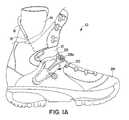
- the sport boot 10 shown in Figs. 1 and 1Aconsists, in a manner understood by those experienced in the art, of an upper 12 having an integral highback 14 with a cable housing 16 fixedly mounted thereto, through which passes a cable 18.
- the highback 14is disposed internally of the visible outer boot portion or upper 12 and the cable housing 16 and cable 18 for tensioning the high back 14 are also preferably routed internally of the boot exterior 12.
- the path of the cable 18 though (i.e., underneath the exterior portion of upper 12) the boot 10is shown in phantom.
- one end of the cable 18is fixedly attached to one side of the boot upper 12 (preferably the medial or instep side of the boot opposite the buckle mechanism 20 ) and enters a dual action buckle mechanism 20 on the other side of the boot 10 such as the lateral side of the boot as shown.
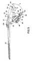
- an instep strap 22(see Figs. 2-5), which attaches at one end to a conventional adjustable receptor (not shown) and at the other to the dual action buckle mechanism 20 mentioned above by an instep strap tensioning member 23.
- Closure of the buckle mechanism 20both draws the cable 18 into itself pulling the highback 14 forward into a riding position (i.e., in a direction towards the toe cap portion 24 of the boot 10), and simultaneously tightens the instep strap 22 to firmly hold the rider's foot against the boot sole.
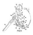
- the dual action buckle mechanism 20 of the present inventioncomprises a primary lever arm 26 pivotally mounted on a frame 28 by an axle or cross pin 30.
- a secondary lever arm 32is pivotally mounted to the primary lever 26, also using an axle or cross pin 34, the centerline of which is a distance L1 from the centerline of the first axle 30.
- the opposite or free end 36 of the secondary lever 32is able to slide along the upper surface 38 of the frame 28, which end 36 is normally held against the upper surface 38 of the frame 28 by means of a biasing spring 40 (see Fig. 5).
- the highback tensioning cable 18travels downward from the highback 14, crosses beneath the buckle frame 28 and is directed through a passageway or hole 29 formed in the frame 28, around a pulley 42 then across the top or upper sliding surface 38 of the frame 28, crossing the path of the sliding end 36 of the secondary lever 32, and finally terminates into a cylindrical slug 44 which is pivotally held in a clip 46 formed in the other side of frame 28 (i.e., on the side of the frame opposite the pulley 42).
- the free end 36 of secondary lever 32has a leading edge that is formed into a shovelling flange 48 which acts to engage and pick up the cable 18 and bring it towards the far end 49 of the frame 28.
- the shovelling flange 48is formed in such a way to cradle the cable 18 like a pulley wheel and thereby permit the cable 18 to slide along the cradle surface of the shovelling flange 48.
- the shovelling flange 48 of free end 36 of the secondary lever 32 over which the cable 18 slidesis forced away from the pivoting axis 30 of the primary lever 26, thus drawing into the mechanism a length of cable approximately equal to twice the distance travelled by the end 36 of the secondary lever 32.
- the secondary lever 32may be disengaged from the cable 18, so that the buckle 20 may be closed without activating the forward lean function of the boot (i.e., without tensioning the highback reinforcement).
- the buckle 20is opened and closed by moving the primary lever as indicated by directional arrow A.
- the frame 28is secured to the boot upper 12 by means of a primary rivet 50. It is understood that the frame 28 may also be removably or fixedly secured to the boot upper in other ways customary to the snowboard boot industry. In addition, the frame 28 may be formed integral with portions of the boot upper material. This is especially advantageous in the case where portions of the boot upper are constructed from strong thermoformable plastic materials.
- the instep strap tensioning member 23has one end pivotally connected to the primary lever 26 at pivot axis 34 and has a secondary rivet 23a or similar fastener connection at its other end.
- the instep strap 22, in turn,is attached to the secondary rivet 23a.
- the opposite end of the instep strap 22is held in a receptor (not shown) on the opposite side of the boot 10.
- a spring loaded hook member 52attached at the free end of the primary lever 26 which engages a tab 54 formed on the far end 49 of the frame 28.
- the hook member 52is biased by its spring to lock the primary lever 26 closed against the frame 28.
- a cam surface 53 formed into the end of the hook member 52slides on the tab 54, opening the hook member 52 until it engages the tab 54. This action positively locks the primary lever 26 closed against the frame 28.
- a finger tab 56 formed into the hook member 52is provided to allow the hook member 52 to be unlocked from the frame 28.
- Fig. 6illustrates an alternate embodiment of the invention, wherein the free end of the primary lever 26 is formed with rigid hook end 58 that includes a nub or projection 60.
- the nub 60is effective to overlap and engage the tab 54 when the primary lever 26 is moved into the fully closed position.
- the locking engagement of the nub 60 with the tab 54is overcome by a moderate level of upward pulling or prying force applied by the user to the rigid hook end 58 of the primary lever 26.
Landscapes
- Footwear And Its Accessory, Manufacturing Method And Apparatuses (AREA)
- Seal Device For Vehicle (AREA)
- Preparation Of Compounds By Using Micro-Organisms (AREA)
- Glass Compositions (AREA)
- Transition And Organic Metals Composition Catalysts For Addition Polymerization (AREA)
- Road Signs Or Road Markings (AREA)
- Vehicle Body Suspensions (AREA)
- Supplying Of Containers To The Packaging Station (AREA)
Abstract
Description
Claims (11)
- A dual action buckle for releasably tightening two portions of a sport boot including astrap oriented along a first axis of the sport boot and a tensioning cable (18) oriented along a secondaxis of the sport boot, wherein said second axis is nonparallel to said first axis, said bucklecomprising:a) a buckle framel (28) adapted to be attached to an upper portion of said sport boot,said buckle frame including a generally planar upper surface bounded by opposed first andsecond end portions and opposed first and second side portions;b) a primary lever (26) including a fulcrum end pivotally connected to said first end ofsaid buckle frame to define a first pivot axis, said primary lever being movable between an openposition and a closed position;c) said primary lever further including a second pivot axis spaced from and parallelto said first pivot axis and pivotally connecting a strap member to said primary lever, said strapmember for tensioning a first portion of said sport boot;d) a secondary lever (32) having a fulcrum end pivotally connected to said second pivotaxis of said primary lever and a free end adapted to slide in a lengthwise direction along saidupper surface of said buckle frame as said primary lever is moved between said open and closedpositions; ande) a tensioning cable (18) for tensioning a second portion of said sport boot, saidtensioning cable having a terminal end retained along one of said side portions of said buckleframe and a cable portion oriented across said buckle frame upper surface and in front of saidsecondary lever free end (36) such that movement of said primary lever into said closed positionsimultaneously tightens the strap member (22) connected to said first sport boot portion and movessaid secondary lever free end into tensioning engagement with said tensioning cable to tightensaid second sport boot portion.
- A dual action buckle according to claim 1, wherein:a) said frame includes a pulley (42) around which the cable is directed; andb) said pulley being effective to provide a mechanical advantage to the dual actionbuckle by doubling the cable retraction action of said secondary lever.
- A dual action buckle according to any of claims 1 to 2, wherein said frame includes ahole (29) through which the cable is routed to pass underneath said upper surface of said buckleframe in one direction.
- A dual action buckle according to any of claims 1 to 3, wherein said free end (36) of saidsecondary lever (32) is formed as a shoveling flange for engaging the cable that is directed across theupper sliding surface of said frame.
- A dual action buckle according to any of claims 1 to 4, wherein said secondary lever (32)may be disengaged from the cable thus allowing the buckle to be closed without retracting thecable.
- A dual action buckle according to any of claims 1 to 5, wherein said first pivot axis (30) ispositioned at a sufficient offset distance relative to said second pivot (34) axis so that when saidbuckle is in a closed position, a tension vector imparted at said second pivot axis passes belowsaid first pivot axis to create an over center condition which acts to urge said primary levertoward said frame and hold the buckle closed.
- A dual action buckle according to any of claims 1 to 6, wherein a spring loaded hookmembers (52) is provided to said primary lever in order to lock it closed to a tab (54) formed in saidframe.
- A dual action buckle according to claim 7, wherein said spring loaded hook member (52)comprises a cam face adapted to slide on said tab (54) and thus move away from said tab when saidprimary lever is moved towards said frame.
- A dual action buckle according to any one of claim 7 to 8, wherein said spring loadedhook member further includes a finger tab (56) which allows said hook to be disengaged fromlocking engagement with said tab of said frame.
- A dual action buckle according to any of claims 1 to 9, wherein said strap memberincludes a tensioning arm and a ratcheting strap.
- A dual action buckle according to claim 10, wherein said tensioning arm and saidratcheting strap are removably attached to one another.
Applications Claiming Priority (4)
| Application Number | Priority Date | Filing Date | Title |
|---|---|---|---|
| US9836697P | 1997-11-14 | 1997-11-14 | |
| US98366P | 1997-11-14 | ||
| US8737098P | 1998-05-26 | 1998-05-26 | |
| PCT/US1998/024184WO1999060878A1 (en) | 1998-05-26 | 1998-11-13 | Dual-action buckle |
Publications (3)
| Publication Number | Publication Date |
|---|---|
| EP1093338A1 EP1093338A1 (en) | 2001-04-25 |
| EP1093338A4 EP1093338A4 (en) | 2002-07-17 |
| EP1093338B1true EP1093338B1 (en) | 2003-06-04 |
Family
ID=22204782
Family Applications (1)
| Application Number | Title | Priority Date | Filing Date |
|---|---|---|---|
| EP98958555AExpired - LifetimeEP1093338B1 (en) | 1997-11-14 | 1998-11-13 | Dual-action buckle |
Country Status (16)
| Country | Link |
|---|---|
| EP (1) | EP1093338B1 (en) |
| JP (1) | JP2002516122A (en) |
| KR (1) | KR20010040383A (en) |
| CN (1) | CN1294501A (en) |
| AT (1) | ATE241923T1 (en) |
| AU (1) | AU1457699A (en) |
| CA (1) | CA2321742A1 (en) |
| DE (1) | DE69815402T2 (en) |
| DK (1) | DK1093338T3 (en) |
| ES (1) | ES2203993T3 (en) |
| IS (1) | IS5678A (en) |
| NO (1) | NO315104B1 (en) |
| NZ (1) | NZ505124A (en) |
| PT (1) | PT1093338E (en) |
| RO (1) | RO119578B1 (en) |
| WO (1) | WO1999060878A1 (en) |
Families Citing this family (7)
| Publication number | Priority date | Publication date | Assignee | Title |
|---|---|---|---|---|
| US7386947B2 (en)* | 2003-02-11 | 2008-06-17 | K-2 Corporation | Snowboard boot with liner harness |
| JP4913337B2 (en)* | 2004-10-28 | 2012-04-11 | アキレス株式会社 | Easy to wear shoes |
| US7306241B2 (en) | 2005-08-29 | 2007-12-11 | The Burton Corporation | Strap for snowboard boots or bindings |
| US7516976B2 (en) | 2005-08-29 | 2009-04-14 | The Burton Corporation | Strap for snowboard boots or bindings |
| US7669880B2 (en) | 2005-08-29 | 2010-03-02 | The Burton Corporation | Strap for snowboard boots or bindings |
| KR20100129278A (en)* | 2008-01-18 | 2010-12-08 | 보아 테크놀러지, 인크. | Closure system |
| KR101539648B1 (en)* | 2014-01-23 | 2015-07-28 | 김은규 | Binding device for clothes and footwear |
Family Cites Families (7)
| Publication number | Priority date | Publication date | Assignee | Title |
|---|---|---|---|---|
| DE3502522A1 (en)* | 1984-02-10 | 1985-08-14 | SALOMON S.A., Annecy, Haute-Savoie | OPERATING LEVER FOR LOCKING AND LOCKING A SKI BOOT WITH REAR ENTRANCE |
| US4677768A (en)* | 1984-02-10 | 1987-07-07 | Salomon S.A. | Rear entry ski boot |
| FR2589690B1 (en)* | 1985-11-12 | 1988-01-29 | Salomon Sa | BACK ENTRY TYPE SKI BOOT |
| CH666795A5 (en) | 1986-01-23 | 1988-08-31 | Lange Int Sa | DEVICE FOR CLOSING A SPORTS SHOE. |
| IT209392Z2 (en)* | 1986-02-06 | 1988-10-05 | Nordica Spa | CLOSING DEVICE FOR LEGS PARTICULARLY FOR SKI BOOTS. |
| CH672400A5 (en)* | 1987-07-21 | 1989-11-30 | Lange Int Sa | |
| IT1225401B (en)* | 1988-08-31 | 1990-11-13 | Nordica Spa | SKI BOOT |
- 1998
- 1998-11-13CACA002321742Apatent/CA2321742A1/ennot_activeAbandoned
- 1998-11-13ESES98958555Tpatent/ES2203993T3/ennot_activeExpired - Lifetime
- 1998-11-13PTPT98958555Tpatent/PT1093338E/enunknown
- 1998-11-13CNCN98814073.XApatent/CN1294501A/enactivePending
- 1998-11-13DKDK98958555Tpatent/DK1093338T3/enactive
- 1998-11-13KRKR1020007008000Apatent/KR20010040383A/ennot_activeAbandoned
- 1998-11-13ROROA200000874Apatent/RO119578B1/enunknown
- 1998-11-13AUAU14576/99Apatent/AU1457699A/ennot_activeAbandoned
- 1998-11-13NZNZ505124Apatent/NZ505124A/enunknown
- 1998-11-13ATAT98958555Tpatent/ATE241923T1/ennot_activeIP Right Cessation
- 1998-11-13WOPCT/US1998/024184patent/WO1999060878A1/enactiveIP Right Grant
- 1998-11-13EPEP98958555Apatent/EP1093338B1/ennot_activeExpired - Lifetime
- 1998-11-13DEDE69815402Tpatent/DE69815402T2/ennot_activeExpired - Fee Related
- 1998-11-13JPJP2000550353Apatent/JP2002516122A/ennot_activeWithdrawn
- 2000
- 2000-09-08NONO20004490Apatent/NO315104B1/ennot_activeIP Right Cessation
- 2000-10-23ISIS5678Apatent/IS5678A/enunknown
Also Published As
| Publication number | Publication date |
|---|---|
| ATE241923T1 (en) | 2003-06-15 |
| CN1294501A (en) | 2001-05-09 |
| PT1093338E (en) | 2003-10-31 |
| EP1093338A1 (en) | 2001-04-25 |
| HK1036740A1 (en) | 2002-01-18 |
| WO1999060878A1 (en) | 1999-12-02 |
| DE69815402T2 (en) | 2004-05-13 |
| NZ505124A (en) | 2002-05-31 |
| DE69815402D1 (en) | 2003-07-10 |
| RO119578B1 (en) | 2005-01-28 |
| NO20004490D0 (en) | 2000-09-08 |
| AU1457699A (en) | 1999-12-13 |
| KR20010040383A (en) | 2001-05-15 |
| JP2002516122A (en) | 2002-06-04 |
| ES2203993T3 (en) | 2004-04-16 |
| IS5678A (en) | 2000-10-23 |
| EP1093338A4 (en) | 2002-07-17 |
| NO315104B1 (en) | 2003-07-14 |
| DK1093338T3 (en) | 2003-09-29 |
| NO20004490L (en) | 2000-09-08 |
| CA2321742A1 (en) | 1999-12-02 |
Similar Documents
| Publication | Publication Date | Title |
|---|---|---|
| US6347436B1 (en) | Dual-action buckle | |
| US7246811B2 (en) | Snowboard binding engagement mechanism | |
| US6554297B2 (en) | Dive resistant buckle | |
| US7568719B2 (en) | Snowboard binding system having automatic toe strap | |
| JP3191000B2 (en) | Snowboard fastening device | |
| JP3361811B2 (en) | Snowboard bindings | |
| US7210252B2 (en) | Step-in snowboard binding and boot therefor | |
| EP1343567B1 (en) | A snow-board binding | |
| US6155577A (en) | Highback lever mechanism | |
| US5971423A (en) | Binding for athletic gear | |
| US6892429B2 (en) | Brake device for a lace | |
| JP2001299984A (en) | Binding device for mounting shoes to snow board | |
| JP2004517665A (en) | Hinge strap for normal snowboard binding | |
| EP1332689B1 (en) | Ski boot | |
| JPH09206420A (en) | Bindings for snowboards | |
| US6412794B1 (en) | Fastening assembly and method for securing footwear to a binding | |
| EP1093338B1 (en) | Dual-action buckle | |
| US6536138B1 (en) | Device for positioning a pair of overlapping flaps | |
| US4908965A (en) | Ski boot fastening device | |
| EP0434902A1 (en) | Adjustable closure device particularly for ski boots | |
| EP3175730B1 (en) | Ski boot | |
| HK1036740B (en) | Dual-action buckle | |
| JPH0318301A (en) | Rear part adjustable type ski boots | |
| EP1044620B1 (en) | Closure device for shoes | |
| JPH0588601B2 (en) |
Legal Events
| Date | Code | Title | Description |
|---|---|---|---|
| PUAI | Public reference made under article 153(3) epc to a published international application that has entered the european phase | Free format text:ORIGINAL CODE: 0009012 | |
| 17P | Request for examination filed | Effective date:20000613 | |
| AK | Designated contracting states | Kind code of ref document:A1 Designated state(s):AT CH DE DK ES FI FR GB IT LI NL PT SE | |
| RIC1 | Information provided on ipc code assigned before grant | Free format text:7A 43C 11/14 A, 7A 43B 5/00 B | |
| A4 | Supplementary search report drawn up and despatched | Effective date:20020531 | |
| AK | Designated contracting states | Kind code of ref document:A4 Designated state(s):AT CH DE DK ES FI FR GB IT LI NL PT SE | |
| RIC1 | Information provided on ipc code assigned before grant | Free format text:7A 43C 11/14 A, 7A 43B 5/04 B | |
| GRAH | Despatch of communication of intention to grant a patent | Free format text:ORIGINAL CODE: EPIDOS IGRA | |
| GRAH | Despatch of communication of intention to grant a patent | Free format text:ORIGINAL CODE: EPIDOS IGRA | |
| GRAA | (expected) grant | Free format text:ORIGINAL CODE: 0009210 | |
| AK | Designated contracting states | Designated state(s):AT CH DE DK ES FI FR GB IT LI NL PT SE | |
| REG | Reference to a national code | Ref country code:GB Ref legal event code:FG4D | |
| REG | Reference to a national code | Ref country code:CH Ref legal event code:EP | |
| REF | Corresponds to: | Ref document number:69815402 Country of ref document:DE Date of ref document:20030710 Kind code of ref document:P | |
| REG | Reference to a national code | Ref country code:SE Ref legal event code:TRGR | |
| REG | Reference to a national code | Ref country code:DK Ref legal event code:T3 | |
| REG | Reference to a national code | Ref country code:CH Ref legal event code:NV Representative=s name:KIRKER & CIE SA | |
| ET | Fr: translation filed | ||
| PLBE | No opposition filed within time limit | Free format text:ORIGINAL CODE: 0009261 | |
| STAA | Information on the status of an ep patent application or granted ep patent | Free format text:STATUS: NO OPPOSITION FILED WITHIN TIME LIMIT | |
| REG | Reference to a national code | Ref country code:ES Ref legal event code:FG2A Ref document number:2203993 Country of ref document:ES Kind code of ref document:T3 | |
| 26N | No opposition filed | Effective date:20040305 | |
| PGFP | Annual fee paid to national office [announced via postgrant information from national office to epo] | Ref country code:NL Payment date:20090531 Year of fee payment:11 Ref country code:ES Payment date:20090529 Year of fee payment:11 Ref country code:DK Payment date:20090511 Year of fee payment:11 | |
| PG25 | Lapsed in a contracting state [announced via postgrant information from national office to epo] | Ref country code:IT Free format text:LAPSE BECAUSE OF NON-PAYMENT OF DUE FEES Effective date:20081113 | |
| PGFP | Annual fee paid to national office [announced via postgrant information from national office to epo] | Ref country code:SE Payment date:20090511 Year of fee payment:11 Ref country code:PT Payment date:20090512 Year of fee payment:11 Ref country code:FR Payment date:20090528 Year of fee payment:11 Ref country code:FI Payment date:20090511 Year of fee payment:11 Ref country code:DE Payment date:20090529 Year of fee payment:11 Ref country code:AT Payment date:20090512 Year of fee payment:11 | |
| PGFP | Annual fee paid to national office [announced via postgrant information from national office to epo] | Ref country code:CH Payment date:20090511 Year of fee payment:11 | |
| PGFP | Annual fee paid to national office [announced via postgrant information from national office to epo] | Ref country code:GB Payment date:20090513 Year of fee payment:11 | |
| REG | Reference to a national code | Ref country code:PT Ref legal event code:MM4A Free format text:LAPSE DUE TO NON-PAYMENT OF FEES Effective date:20100514 | |
| REG | Reference to a national code | Ref country code:NL Ref legal event code:V1 Effective date:20100601 | |
| EUG | Se: european patent has lapsed | ||
| REG | Reference to a national code | Ref country code:CH Ref legal event code:PL | |
| REG | Reference to a national code | Ref country code:DK Ref legal event code:EBP | |
| GBPC | Gb: european patent ceased through non-payment of renewal fee | Effective date:20091113 | |
| PG25 | Lapsed in a contracting state [announced via postgrant information from national office to epo] | Ref country code:PT Free format text:LAPSE BECAUSE OF NON-PAYMENT OF DUE FEES Effective date:20100514 | |
| REG | Reference to a national code | Ref country code:FR Ref legal event code:ST Effective date:20100730 | |
| PG25 | Lapsed in a contracting state [announced via postgrant information from national office to epo] | Ref country code:FI Free format text:LAPSE BECAUSE OF NON-PAYMENT OF DUE FEES Effective date:20091113 Ref country code:AT Free format text:LAPSE BECAUSE OF NON-PAYMENT OF DUE FEES Effective date:20091113 | |
| PG25 | Lapsed in a contracting state [announced via postgrant information from national office to epo] | Ref country code:NL Free format text:LAPSE BECAUSE OF NON-PAYMENT OF DUE FEES Effective date:20100601 Ref country code:LI Free format text:LAPSE BECAUSE OF NON-PAYMENT OF DUE FEES Effective date:20091130 Ref country code:FR Free format text:LAPSE BECAUSE OF NON-PAYMENT OF DUE FEES Effective date:20091130 Ref country code:CH Free format text:LAPSE BECAUSE OF NON-PAYMENT OF DUE FEES Effective date:20091130 | |
| PG25 | Lapsed in a contracting state [announced via postgrant information from national office to epo] | Ref country code:DE Free format text:LAPSE BECAUSE OF NON-PAYMENT OF DUE FEES Effective date:20100601 | |
| PG25 | Lapsed in a contracting state [announced via postgrant information from national office to epo] | Ref country code:GB Free format text:LAPSE BECAUSE OF NON-PAYMENT OF DUE FEES Effective date:20091113 | |
| PG25 | Lapsed in a contracting state [announced via postgrant information from national office to epo] | Ref country code:DK Free format text:LAPSE BECAUSE OF NON-PAYMENT OF DUE FEES Effective date:20091130 | |
| REG | Reference to a national code | Ref country code:ES Ref legal event code:FD2A Effective date:20110310 | |
| PG25 | Lapsed in a contracting state [announced via postgrant information from national office to epo] | Ref country code:SE Free format text:LAPSE BECAUSE OF NON-PAYMENT OF DUE FEES Effective date:20091114 | |
| PG25 | Lapsed in a contracting state [announced via postgrant information from national office to epo] | Ref country code:ES Free format text:LAPSE BECAUSE OF NON-PAYMENT OF DUE FEES Effective date:20110309 | |
| PGFP | Annual fee paid to national office [announced via postgrant information from national office to epo] | Ref country code:IT Payment date:20090515 Year of fee payment:11 | |
| PGRI | Patent reinstated in contracting state [announced from national office to epo] | Ref country code:IT Effective date:20110616 | |
| PG25 | Lapsed in a contracting state [announced via postgrant information from national office to epo] | Ref country code:ES Free format text:LAPSE BECAUSE OF NON-PAYMENT OF DUE FEES Effective date:20091114 | |
| PGRI | Patent reinstated in contracting state [announced from national office to epo] | Ref country code:IT Effective date:20110616 |