EP1088533A1 - Basket-style container for implanting bone tissue - Google Patents
Basket-style container for implanting bone tissueDownload PDFInfo
- Publication number
- EP1088533A1 EP1088533A1EP00810773AEP00810773AEP1088533A1EP 1088533 A1EP1088533 A1EP 1088533A1EP 00810773 AEP00810773 AEP 00810773AEP 00810773 AEP00810773 AEP 00810773AEP 1088533 A1EP1088533 A1EP 1088533A1
- Authority
- EP
- European Patent Office
- Prior art keywords
- container
- wall
- wires
- bone tissue
- axis
- Prior art date
- Legal status (The legal status is an assumption and is not a legal conclusion. Google has not performed a legal analysis and makes no representation as to the accuracy of the status listed.)
- Granted
Links
- 210000000988bone and boneAnatomy0.000titleclaimsabstractdescription21
- 239000004744fabricSubstances0.000claimsabstractdescription6
- 230000002093peripheral effectEffects0.000claimsabstractdescription6
- 238000001356surgical procedureMethods0.000claimsdescription6
- 238000007689inspectionMethods0.000claimsdescription4
- 230000003287optical effectEffects0.000claimsdescription4
- 210000001519tissueAnatomy0.000claimsdescription4
- 238000004873anchoringMethods0.000claimsdescription3
- 239000000463materialSubstances0.000claimsdescription3
- RTAQQCXQSZGOHL-UHFFFAOYSA-NTitaniumChemical compound[Ti]RTAQQCXQSZGOHL-UHFFFAOYSA-N0.000claimsdescription2
- 238000002513implantationMethods0.000claimsdescription2
- 238000012856packingMethods0.000claimsdescription2
- 230000002787reinforcementEffects0.000claimsdescription2
- 239000010936titaniumSubstances0.000claimsdescription2
- 229910052719titaniumInorganic materials0.000claimsdescription2
- 230000003014reinforcing effectEffects0.000claims1
- 239000007943implantSubstances0.000description5
- 230000001172regenerating effectEffects0.000description3
- 208000007623LordosisDiseases0.000description1
- 206010028980NeoplasmDiseases0.000description1
- 229910045601alloyInorganic materials0.000description1
- 239000000956alloySubstances0.000description1
- 230000001427coherent effectEffects0.000description1
- 230000002950deficientEffects0.000description1
- 230000001419dependent effectEffects0.000description1
- 238000002405diagnostic procedureMethods0.000description1
- 210000004705lumbosacral regionAnatomy0.000description1
- 229910052751metalInorganic materials0.000description1
- 239000002184metalSubstances0.000description1
- 150000002739metalsChemical class0.000description1
- 125000006850spacer groupChemical group0.000description1
- 230000009772tissue formationEffects0.000description1
- 238000011282treatmentMethods0.000description1
- 210000000051wattleAnatomy0.000description1
Images


Classifications
- A—HUMAN NECESSITIES
- A61—MEDICAL OR VETERINARY SCIENCE; HYGIENE
- A61F—FILTERS IMPLANTABLE INTO BLOOD VESSELS; PROSTHESES; DEVICES PROVIDING PATENCY TO, OR PREVENTING COLLAPSING OF, TUBULAR STRUCTURES OF THE BODY, e.g. STENTS; ORTHOPAEDIC, NURSING OR CONTRACEPTIVE DEVICES; FOMENTATION; TREATMENT OR PROTECTION OF EYES OR EARS; BANDAGES, DRESSINGS OR ABSORBENT PADS; FIRST-AID KITS
- A61F2/00—Filters implantable into blood vessels; Prostheses, i.e. artificial substitutes or replacements for parts of the body; Appliances for connecting them with the body; Devices providing patency to, or preventing collapsing of, tubular structures of the body, e.g. stents
- A61F2/02—Prostheses implantable into the body
- A61F2/30—Joints
- A61F2/44—Joints for the spine, e.g. vertebrae, spinal discs
- A61F2/4455—Joints for the spine, e.g. vertebrae, spinal discs for the fusion of spinal bodies, e.g. intervertebral fusion of adjacent spinal bodies, e.g. fusion cages
- A—HUMAN NECESSITIES
- A61—MEDICAL OR VETERINARY SCIENCE; HYGIENE
- A61F—FILTERS IMPLANTABLE INTO BLOOD VESSELS; PROSTHESES; DEVICES PROVIDING PATENCY TO, OR PREVENTING COLLAPSING OF, TUBULAR STRUCTURES OF THE BODY, e.g. STENTS; ORTHOPAEDIC, NURSING OR CONTRACEPTIVE DEVICES; FOMENTATION; TREATMENT OR PROTECTION OF EYES OR EARS; BANDAGES, DRESSINGS OR ABSORBENT PADS; FIRST-AID KITS
- A61F2/00—Filters implantable into blood vessels; Prostheses, i.e. artificial substitutes or replacements for parts of the body; Appliances for connecting them with the body; Devices providing patency to, or preventing collapsing of, tubular structures of the body, e.g. stents
- A61F2/02—Prostheses implantable into the body
- A61F2/28—Bones
- A61F2/2846—Support means for bone substitute or for bone graft implants, e.g. membranes or plates for covering bone defects
- A—HUMAN NECESSITIES
- A61—MEDICAL OR VETERINARY SCIENCE; HYGIENE
- A61F—FILTERS IMPLANTABLE INTO BLOOD VESSELS; PROSTHESES; DEVICES PROVIDING PATENCY TO, OR PREVENTING COLLAPSING OF, TUBULAR STRUCTURES OF THE BODY, e.g. STENTS; ORTHOPAEDIC, NURSING OR CONTRACEPTIVE DEVICES; FOMENTATION; TREATMENT OR PROTECTION OF EYES OR EARS; BANDAGES, DRESSINGS OR ABSORBENT PADS; FIRST-AID KITS
- A61F2/00—Filters implantable into blood vessels; Prostheses, i.e. artificial substitutes or replacements for parts of the body; Appliances for connecting them with the body; Devices providing patency to, or preventing collapsing of, tubular structures of the body, e.g. stents
- A61F2/02—Prostheses implantable into the body
- A61F2/30—Joints
- A61F2/44—Joints for the spine, e.g. vertebrae, spinal discs
- A61F2/442—Intervertebral or spinal discs, e.g. resilient
- A—HUMAN NECESSITIES
- A61—MEDICAL OR VETERINARY SCIENCE; HYGIENE
- A61F—FILTERS IMPLANTABLE INTO BLOOD VESSELS; PROSTHESES; DEVICES PROVIDING PATENCY TO, OR PREVENTING COLLAPSING OF, TUBULAR STRUCTURES OF THE BODY, e.g. STENTS; ORTHOPAEDIC, NURSING OR CONTRACEPTIVE DEVICES; FOMENTATION; TREATMENT OR PROTECTION OF EYES OR EARS; BANDAGES, DRESSINGS OR ABSORBENT PADS; FIRST-AID KITS
- A61F2/00—Filters implantable into blood vessels; Prostheses, i.e. artificial substitutes or replacements for parts of the body; Appliances for connecting them with the body; Devices providing patency to, or preventing collapsing of, tubular structures of the body, e.g. stents
- A61F2/02—Prostheses implantable into the body
- A61F2/28—Bones
- A61F2002/2835—Bone graft implants for filling a bony defect or an endoprosthesis cavity, e.g. by synthetic material or biological material
- A—HUMAN NECESSITIES
- A61—MEDICAL OR VETERINARY SCIENCE; HYGIENE
- A61F—FILTERS IMPLANTABLE INTO BLOOD VESSELS; PROSTHESES; DEVICES PROVIDING PATENCY TO, OR PREVENTING COLLAPSING OF, TUBULAR STRUCTURES OF THE BODY, e.g. STENTS; ORTHOPAEDIC, NURSING OR CONTRACEPTIVE DEVICES; FOMENTATION; TREATMENT OR PROTECTION OF EYES OR EARS; BANDAGES, DRESSINGS OR ABSORBENT PADS; FIRST-AID KITS
- A61F2/00—Filters implantable into blood vessels; Prostheses, i.e. artificial substitutes or replacements for parts of the body; Appliances for connecting them with the body; Devices providing patency to, or preventing collapsing of, tubular structures of the body, e.g. stents
- A61F2/02—Prostheses implantable into the body
- A61F2/30—Joints
- A61F2002/30001—Additional features of subject-matter classified in A61F2/28, A61F2/30 and subgroups thereof
- A61F2002/30003—Material related properties of the prosthesis or of a coating on the prosthesis
- A61F2002/3006—Properties of materials and coating materials
- A61F2002/30062—(bio)absorbable, biodegradable, bioerodable, (bio)resorbable, resorptive
- A—HUMAN NECESSITIES
- A61—MEDICAL OR VETERINARY SCIENCE; HYGIENE
- A61F—FILTERS IMPLANTABLE INTO BLOOD VESSELS; PROSTHESES; DEVICES PROVIDING PATENCY TO, OR PREVENTING COLLAPSING OF, TUBULAR STRUCTURES OF THE BODY, e.g. STENTS; ORTHOPAEDIC, NURSING OR CONTRACEPTIVE DEVICES; FOMENTATION; TREATMENT OR PROTECTION OF EYES OR EARS; BANDAGES, DRESSINGS OR ABSORBENT PADS; FIRST-AID KITS
- A61F2/00—Filters implantable into blood vessels; Prostheses, i.e. artificial substitutes or replacements for parts of the body; Appliances for connecting them with the body; Devices providing patency to, or preventing collapsing of, tubular structures of the body, e.g. stents
- A61F2/02—Prostheses implantable into the body
- A61F2/30—Joints
- A61F2002/30001—Additional features of subject-matter classified in A61F2/28, A61F2/30 and subgroups thereof
- A61F2002/30108—Shapes
- A61F2002/3011—Cross-sections or two-dimensional shapes
- A61F2002/30112—Rounded shapes, e.g. with rounded corners
- A61F2002/30113—Rounded shapes, e.g. with rounded corners circular
- A61F2002/30115—Rounded shapes, e.g. with rounded corners circular circular-O-shaped
- A—HUMAN NECESSITIES
- A61—MEDICAL OR VETERINARY SCIENCE; HYGIENE
- A61F—FILTERS IMPLANTABLE INTO BLOOD VESSELS; PROSTHESES; DEVICES PROVIDING PATENCY TO, OR PREVENTING COLLAPSING OF, TUBULAR STRUCTURES OF THE BODY, e.g. STENTS; ORTHOPAEDIC, NURSING OR CONTRACEPTIVE DEVICES; FOMENTATION; TREATMENT OR PROTECTION OF EYES OR EARS; BANDAGES, DRESSINGS OR ABSORBENT PADS; FIRST-AID KITS
- A61F2/00—Filters implantable into blood vessels; Prostheses, i.e. artificial substitutes or replacements for parts of the body; Appliances for connecting them with the body; Devices providing patency to, or preventing collapsing of, tubular structures of the body, e.g. stents
- A61F2/02—Prostheses implantable into the body
- A61F2/30—Joints
- A61F2002/30001—Additional features of subject-matter classified in A61F2/28, A61F2/30 and subgroups thereof
- A61F2002/30108—Shapes
- A61F2002/3011—Cross-sections or two-dimensional shapes
- A61F2002/30138—Convex polygonal shapes
- A61F2002/30143—Convex polygonal shapes hexagonal
- A—HUMAN NECESSITIES
- A61—MEDICAL OR VETERINARY SCIENCE; HYGIENE
- A61F—FILTERS IMPLANTABLE INTO BLOOD VESSELS; PROSTHESES; DEVICES PROVIDING PATENCY TO, OR PREVENTING COLLAPSING OF, TUBULAR STRUCTURES OF THE BODY, e.g. STENTS; ORTHOPAEDIC, NURSING OR CONTRACEPTIVE DEVICES; FOMENTATION; TREATMENT OR PROTECTION OF EYES OR EARS; BANDAGES, DRESSINGS OR ABSORBENT PADS; FIRST-AID KITS
- A61F2/00—Filters implantable into blood vessels; Prostheses, i.e. artificial substitutes or replacements for parts of the body; Appliances for connecting them with the body; Devices providing patency to, or preventing collapsing of, tubular structures of the body, e.g. stents
- A61F2/02—Prostheses implantable into the body
- A61F2/30—Joints
- A61F2002/30001—Additional features of subject-matter classified in A61F2/28, A61F2/30 and subgroups thereof
- A61F2002/30108—Shapes
- A61F2002/3011—Cross-sections or two-dimensional shapes
- A61F2002/30138—Convex polygonal shapes
- A61F2002/30153—Convex polygonal shapes rectangular
- A—HUMAN NECESSITIES
- A61—MEDICAL OR VETERINARY SCIENCE; HYGIENE
- A61F—FILTERS IMPLANTABLE INTO BLOOD VESSELS; PROSTHESES; DEVICES PROVIDING PATENCY TO, OR PREVENTING COLLAPSING OF, TUBULAR STRUCTURES OF THE BODY, e.g. STENTS; ORTHOPAEDIC, NURSING OR CONTRACEPTIVE DEVICES; FOMENTATION; TREATMENT OR PROTECTION OF EYES OR EARS; BANDAGES, DRESSINGS OR ABSORBENT PADS; FIRST-AID KITS
- A61F2/00—Filters implantable into blood vessels; Prostheses, i.e. artificial substitutes or replacements for parts of the body; Appliances for connecting them with the body; Devices providing patency to, or preventing collapsing of, tubular structures of the body, e.g. stents
- A61F2/02—Prostheses implantable into the body
- A61F2/30—Joints
- A61F2002/30001—Additional features of subject-matter classified in A61F2/28, A61F2/30 and subgroups thereof
- A61F2002/30108—Shapes
- A61F2002/3011—Cross-sections or two-dimensional shapes
- A61F2002/30182—Other shapes
- A61F2002/30187—D-shaped or half-disc-shaped
- A—HUMAN NECESSITIES
- A61—MEDICAL OR VETERINARY SCIENCE; HYGIENE
- A61F—FILTERS IMPLANTABLE INTO BLOOD VESSELS; PROSTHESES; DEVICES PROVIDING PATENCY TO, OR PREVENTING COLLAPSING OF, TUBULAR STRUCTURES OF THE BODY, e.g. STENTS; ORTHOPAEDIC, NURSING OR CONTRACEPTIVE DEVICES; FOMENTATION; TREATMENT OR PROTECTION OF EYES OR EARS; BANDAGES, DRESSINGS OR ABSORBENT PADS; FIRST-AID KITS
- A61F2/00—Filters implantable into blood vessels; Prostheses, i.e. artificial substitutes or replacements for parts of the body; Appliances for connecting them with the body; Devices providing patency to, or preventing collapsing of, tubular structures of the body, e.g. stents
- A61F2/02—Prostheses implantable into the body
- A61F2/30—Joints
- A61F2002/30001—Additional features of subject-matter classified in A61F2/28, A61F2/30 and subgroups thereof
- A61F2002/30108—Shapes
- A61F2002/30199—Three-dimensional shapes
- A61F2002/302—Three-dimensional shapes toroidal, e.g. rings
- A—HUMAN NECESSITIES
- A61—MEDICAL OR VETERINARY SCIENCE; HYGIENE
- A61F—FILTERS IMPLANTABLE INTO BLOOD VESSELS; PROSTHESES; DEVICES PROVIDING PATENCY TO, OR PREVENTING COLLAPSING OF, TUBULAR STRUCTURES OF THE BODY, e.g. STENTS; ORTHOPAEDIC, NURSING OR CONTRACEPTIVE DEVICES; FOMENTATION; TREATMENT OR PROTECTION OF EYES OR EARS; BANDAGES, DRESSINGS OR ABSORBENT PADS; FIRST-AID KITS
- A61F2/00—Filters implantable into blood vessels; Prostheses, i.e. artificial substitutes or replacements for parts of the body; Appliances for connecting them with the body; Devices providing patency to, or preventing collapsing of, tubular structures of the body, e.g. stents
- A61F2/02—Prostheses implantable into the body
- A61F2/30—Joints
- A61F2002/30001—Additional features of subject-matter classified in A61F2/28, A61F2/30 and subgroups thereof
- A61F2002/30108—Shapes
- A61F2002/30199—Three-dimensional shapes
- A61F2002/30224—Three-dimensional shapes cylindrical
- A61F2002/3023—Three-dimensional shapes cylindrical wedge-shaped cylinders
- A—HUMAN NECESSITIES
- A61—MEDICAL OR VETERINARY SCIENCE; HYGIENE
- A61F—FILTERS IMPLANTABLE INTO BLOOD VESSELS; PROSTHESES; DEVICES PROVIDING PATENCY TO, OR PREVENTING COLLAPSING OF, TUBULAR STRUCTURES OF THE BODY, e.g. STENTS; ORTHOPAEDIC, NURSING OR CONTRACEPTIVE DEVICES; FOMENTATION; TREATMENT OR PROTECTION OF EYES OR EARS; BANDAGES, DRESSINGS OR ABSORBENT PADS; FIRST-AID KITS
- A61F2/00—Filters implantable into blood vessels; Prostheses, i.e. artificial substitutes or replacements for parts of the body; Appliances for connecting them with the body; Devices providing patency to, or preventing collapsing of, tubular structures of the body, e.g. stents
- A61F2/02—Prostheses implantable into the body
- A61F2/30—Joints
- A61F2002/30001—Additional features of subject-matter classified in A61F2/28, A61F2/30 and subgroups thereof
- A61F2002/30108—Shapes
- A61F2002/30199—Three-dimensional shapes
- A61F2002/30224—Three-dimensional shapes cylindrical
- A61F2002/30235—Three-dimensional shapes cylindrical tubular, e.g. sleeves
- A61F2002/30237—Three-dimensional shapes cylindrical tubular, e.g. sleeves partial tubes
- A—HUMAN NECESSITIES
- A61—MEDICAL OR VETERINARY SCIENCE; HYGIENE
- A61F—FILTERS IMPLANTABLE INTO BLOOD VESSELS; PROSTHESES; DEVICES PROVIDING PATENCY TO, OR PREVENTING COLLAPSING OF, TUBULAR STRUCTURES OF THE BODY, e.g. STENTS; ORTHOPAEDIC, NURSING OR CONTRACEPTIVE DEVICES; FOMENTATION; TREATMENT OR PROTECTION OF EYES OR EARS; BANDAGES, DRESSINGS OR ABSORBENT PADS; FIRST-AID KITS
- A61F2/00—Filters implantable into blood vessels; Prostheses, i.e. artificial substitutes or replacements for parts of the body; Appliances for connecting them with the body; Devices providing patency to, or preventing collapsing of, tubular structures of the body, e.g. stents
- A61F2/02—Prostheses implantable into the body
- A61F2/30—Joints
- A61F2002/30001—Additional features of subject-matter classified in A61F2/28, A61F2/30 and subgroups thereof
- A61F2002/30108—Shapes
- A61F2002/30199—Three-dimensional shapes
- A61F2002/30261—Three-dimensional shapes parallelepipedal
- A—HUMAN NECESSITIES
- A61—MEDICAL OR VETERINARY SCIENCE; HYGIENE
- A61F—FILTERS IMPLANTABLE INTO BLOOD VESSELS; PROSTHESES; DEVICES PROVIDING PATENCY TO, OR PREVENTING COLLAPSING OF, TUBULAR STRUCTURES OF THE BODY, e.g. STENTS; ORTHOPAEDIC, NURSING OR CONTRACEPTIVE DEVICES; FOMENTATION; TREATMENT OR PROTECTION OF EYES OR EARS; BANDAGES, DRESSINGS OR ABSORBENT PADS; FIRST-AID KITS
- A61F2/00—Filters implantable into blood vessels; Prostheses, i.e. artificial substitutes or replacements for parts of the body; Appliances for connecting them with the body; Devices providing patency to, or preventing collapsing of, tubular structures of the body, e.g. stents
- A61F2/02—Prostheses implantable into the body
- A61F2/30—Joints
- A61F2002/30001—Additional features of subject-matter classified in A61F2/28, A61F2/30 and subgroups thereof
- A61F2002/30108—Shapes
- A61F2002/30199—Three-dimensional shapes
- A61F2002/3028—Three-dimensional shapes polyhedral different from parallelepipedal and pyramidal
- A—HUMAN NECESSITIES
- A61—MEDICAL OR VETERINARY SCIENCE; HYGIENE
- A61F—FILTERS IMPLANTABLE INTO BLOOD VESSELS; PROSTHESES; DEVICES PROVIDING PATENCY TO, OR PREVENTING COLLAPSING OF, TUBULAR STRUCTURES OF THE BODY, e.g. STENTS; ORTHOPAEDIC, NURSING OR CONTRACEPTIVE DEVICES; FOMENTATION; TREATMENT OR PROTECTION OF EYES OR EARS; BANDAGES, DRESSINGS OR ABSORBENT PADS; FIRST-AID KITS
- A61F2/00—Filters implantable into blood vessels; Prostheses, i.e. artificial substitutes or replacements for parts of the body; Appliances for connecting them with the body; Devices providing patency to, or preventing collapsing of, tubular structures of the body, e.g. stents
- A61F2/02—Prostheses implantable into the body
- A61F2/30—Joints
- A61F2002/30001—Additional features of subject-matter classified in A61F2/28, A61F2/30 and subgroups thereof
- A61F2002/30316—The prosthesis having different structural features at different locations within the same prosthesis; Connections between prosthetic parts; Special structural features of bone or joint prostheses not otherwise provided for
- A61F2002/30317—The prosthesis having different structural features at different locations within the same prosthesis
- A61F2002/30327—The prosthesis having different structural features at different locations within the same prosthesis differing in diameter
- A—HUMAN NECESSITIES
- A61—MEDICAL OR VETERINARY SCIENCE; HYGIENE
- A61F—FILTERS IMPLANTABLE INTO BLOOD VESSELS; PROSTHESES; DEVICES PROVIDING PATENCY TO, OR PREVENTING COLLAPSING OF, TUBULAR STRUCTURES OF THE BODY, e.g. STENTS; ORTHOPAEDIC, NURSING OR CONTRACEPTIVE DEVICES; FOMENTATION; TREATMENT OR PROTECTION OF EYES OR EARS; BANDAGES, DRESSINGS OR ABSORBENT PADS; FIRST-AID KITS
- A61F2/00—Filters implantable into blood vessels; Prostheses, i.e. artificial substitutes or replacements for parts of the body; Appliances for connecting them with the body; Devices providing patency to, or preventing collapsing of, tubular structures of the body, e.g. stents
- A61F2/02—Prostheses implantable into the body
- A61F2/30—Joints
- A61F2002/30001—Additional features of subject-matter classified in A61F2/28, A61F2/30 and subgroups thereof
- A61F2002/30316—The prosthesis having different structural features at different locations within the same prosthesis; Connections between prosthetic parts; Special structural features of bone or joint prostheses not otherwise provided for
- A61F2002/30329—Connections or couplings between prosthetic parts, e.g. between modular parts; Connecting elements
- A61F2002/30451—Connections or couplings between prosthetic parts, e.g. between modular parts; Connecting elements soldered or brazed or welded
- A—HUMAN NECESSITIES
- A61—MEDICAL OR VETERINARY SCIENCE; HYGIENE
- A61F—FILTERS IMPLANTABLE INTO BLOOD VESSELS; PROSTHESES; DEVICES PROVIDING PATENCY TO, OR PREVENTING COLLAPSING OF, TUBULAR STRUCTURES OF THE BODY, e.g. STENTS; ORTHOPAEDIC, NURSING OR CONTRACEPTIVE DEVICES; FOMENTATION; TREATMENT OR PROTECTION OF EYES OR EARS; BANDAGES, DRESSINGS OR ABSORBENT PADS; FIRST-AID KITS
- A61F2/00—Filters implantable into blood vessels; Prostheses, i.e. artificial substitutes or replacements for parts of the body; Appliances for connecting them with the body; Devices providing patency to, or preventing collapsing of, tubular structures of the body, e.g. stents
- A61F2/02—Prostheses implantable into the body
- A61F2/30—Joints
- A61F2002/30001—Additional features of subject-matter classified in A61F2/28, A61F2/30 and subgroups thereof
- A61F2002/30316—The prosthesis having different structural features at different locations within the same prosthesis; Connections between prosthetic parts; Special structural features of bone or joint prostheses not otherwise provided for
- A61F2002/30535—Special structural features of bone or joint prostheses not otherwise provided for
- A61F2002/30593—Special structural features of bone or joint prostheses not otherwise provided for hollow
- A—HUMAN NECESSITIES
- A61—MEDICAL OR VETERINARY SCIENCE; HYGIENE
- A61F—FILTERS IMPLANTABLE INTO BLOOD VESSELS; PROSTHESES; DEVICES PROVIDING PATENCY TO, OR PREVENTING COLLAPSING OF, TUBULAR STRUCTURES OF THE BODY, e.g. STENTS; ORTHOPAEDIC, NURSING OR CONTRACEPTIVE DEVICES; FOMENTATION; TREATMENT OR PROTECTION OF EYES OR EARS; BANDAGES, DRESSINGS OR ABSORBENT PADS; FIRST-AID KITS
- A61F2/00—Filters implantable into blood vessels; Prostheses, i.e. artificial substitutes or replacements for parts of the body; Appliances for connecting them with the body; Devices providing patency to, or preventing collapsing of, tubular structures of the body, e.g. stents
- A61F2/02—Prostheses implantable into the body
- A61F2/30—Joints
- A61F2/30767—Special external or bone-contacting surface, e.g. coating for improving bone ingrowth
- A61F2/30771—Special external or bone-contacting surface, e.g. coating for improving bone ingrowth applied in original prostheses, e.g. holes or grooves
- A61F2002/30772—Apertures or holes, e.g. of circular cross section
- A—HUMAN NECESSITIES
- A61—MEDICAL OR VETERINARY SCIENCE; HYGIENE
- A61F—FILTERS IMPLANTABLE INTO BLOOD VESSELS; PROSTHESES; DEVICES PROVIDING PATENCY TO, OR PREVENTING COLLAPSING OF, TUBULAR STRUCTURES OF THE BODY, e.g. STENTS; ORTHOPAEDIC, NURSING OR CONTRACEPTIVE DEVICES; FOMENTATION; TREATMENT OR PROTECTION OF EYES OR EARS; BANDAGES, DRESSINGS OR ABSORBENT PADS; FIRST-AID KITS
- A61F2/00—Filters implantable into blood vessels; Prostheses, i.e. artificial substitutes or replacements for parts of the body; Appliances for connecting them with the body; Devices providing patency to, or preventing collapsing of, tubular structures of the body, e.g. stents
- A61F2/02—Prostheses implantable into the body
- A61F2/30—Joints
- A61F2/30767—Special external or bone-contacting surface, e.g. coating for improving bone ingrowth
- A61F2/30771—Special external or bone-contacting surface, e.g. coating for improving bone ingrowth applied in original prostheses, e.g. holes or grooves
- A61F2002/30841—Sharp anchoring protrusions for impaction into the bone, e.g. sharp pins, spikes
- A—HUMAN NECESSITIES
- A61—MEDICAL OR VETERINARY SCIENCE; HYGIENE
- A61F—FILTERS IMPLANTABLE INTO BLOOD VESSELS; PROSTHESES; DEVICES PROVIDING PATENCY TO, OR PREVENTING COLLAPSING OF, TUBULAR STRUCTURES OF THE BODY, e.g. STENTS; ORTHOPAEDIC, NURSING OR CONTRACEPTIVE DEVICES; FOMENTATION; TREATMENT OR PROTECTION OF EYES OR EARS; BANDAGES, DRESSINGS OR ABSORBENT PADS; FIRST-AID KITS
- A61F2/00—Filters implantable into blood vessels; Prostheses, i.e. artificial substitutes or replacements for parts of the body; Appliances for connecting them with the body; Devices providing patency to, or preventing collapsing of, tubular structures of the body, e.g. stents
- A61F2/02—Prostheses implantable into the body
- A61F2/30—Joints
- A61F2/30767—Special external or bone-contacting surface, e.g. coating for improving bone ingrowth
- A61F2/30771—Special external or bone-contacting surface, e.g. coating for improving bone ingrowth applied in original prostheses, e.g. holes or grooves
- A61F2002/30878—Special external or bone-contacting surface, e.g. coating for improving bone ingrowth applied in original prostheses, e.g. holes or grooves with non-sharp protrusions, for instance contacting the bone for anchoring, e.g. keels, pegs, pins, posts, shanks, stems, struts
- A61F2002/30891—Plurality of protrusions
- A61F2002/30892—Plurality of protrusions parallel
- A—HUMAN NECESSITIES
- A61—MEDICAL OR VETERINARY SCIENCE; HYGIENE
- A61F—FILTERS IMPLANTABLE INTO BLOOD VESSELS; PROSTHESES; DEVICES PROVIDING PATENCY TO, OR PREVENTING COLLAPSING OF, TUBULAR STRUCTURES OF THE BODY, e.g. STENTS; ORTHOPAEDIC, NURSING OR CONTRACEPTIVE DEVICES; FOMENTATION; TREATMENT OR PROTECTION OF EYES OR EARS; BANDAGES, DRESSINGS OR ABSORBENT PADS; FIRST-AID KITS
- A61F2/00—Filters implantable into blood vessels; Prostheses, i.e. artificial substitutes or replacements for parts of the body; Appliances for connecting them with the body; Devices providing patency to, or preventing collapsing of, tubular structures of the body, e.g. stents
- A61F2/02—Prostheses implantable into the body
- A61F2/30—Joints
- A61F2/30767—Special external or bone-contacting surface, e.g. coating for improving bone ingrowth
- A61F2/30907—Nets or sleeves applied to surface of prostheses or in cement
- A61F2002/30909—Nets
- A61F2002/30914—Details of the mesh structure, e.g. disposition of the woven warp and weft wires
- A—HUMAN NECESSITIES
- A61—MEDICAL OR VETERINARY SCIENCE; HYGIENE
- A61F—FILTERS IMPLANTABLE INTO BLOOD VESSELS; PROSTHESES; DEVICES PROVIDING PATENCY TO, OR PREVENTING COLLAPSING OF, TUBULAR STRUCTURES OF THE BODY, e.g. STENTS; ORTHOPAEDIC, NURSING OR CONTRACEPTIVE DEVICES; FOMENTATION; TREATMENT OR PROTECTION OF EYES OR EARS; BANDAGES, DRESSINGS OR ABSORBENT PADS; FIRST-AID KITS
- A61F2/00—Filters implantable into blood vessels; Prostheses, i.e. artificial substitutes or replacements for parts of the body; Appliances for connecting them with the body; Devices providing patency to, or preventing collapsing of, tubular structures of the body, e.g. stents
- A61F2/02—Prostheses implantable into the body
- A61F2/30—Joints
- A61F2/3094—Designing or manufacturing processes
- A61F2002/30975—Designing or manufacturing processes made of two halves
- A—HUMAN NECESSITIES
- A61—MEDICAL OR VETERINARY SCIENCE; HYGIENE
- A61F—FILTERS IMPLANTABLE INTO BLOOD VESSELS; PROSTHESES; DEVICES PROVIDING PATENCY TO, OR PREVENTING COLLAPSING OF, TUBULAR STRUCTURES OF THE BODY, e.g. STENTS; ORTHOPAEDIC, NURSING OR CONTRACEPTIVE DEVICES; FOMENTATION; TREATMENT OR PROTECTION OF EYES OR EARS; BANDAGES, DRESSINGS OR ABSORBENT PADS; FIRST-AID KITS
- A61F2/00—Filters implantable into blood vessels; Prostheses, i.e. artificial substitutes or replacements for parts of the body; Appliances for connecting them with the body; Devices providing patency to, or preventing collapsing of, tubular structures of the body, e.g. stents
- A61F2/02—Prostheses implantable into the body
- A61F2/30—Joints
- A61F2/44—Joints for the spine, e.g. vertebrae, spinal discs
- A61F2002/448—Joints for the spine, e.g. vertebrae, spinal discs comprising multiple adjacent spinal implants within the same intervertebral space or within the same vertebra, e.g. comprising two adjacent spinal implants
- A—HUMAN NECESSITIES
- A61—MEDICAL OR VETERINARY SCIENCE; HYGIENE
- A61F—FILTERS IMPLANTABLE INTO BLOOD VESSELS; PROSTHESES; DEVICES PROVIDING PATENCY TO, OR PREVENTING COLLAPSING OF, TUBULAR STRUCTURES OF THE BODY, e.g. STENTS; ORTHOPAEDIC, NURSING OR CONTRACEPTIVE DEVICES; FOMENTATION; TREATMENT OR PROTECTION OF EYES OR EARS; BANDAGES, DRESSINGS OR ABSORBENT PADS; FIRST-AID KITS
- A61F2210/00—Particular material properties of prostheses classified in groups A61F2/00 - A61F2/26 or A61F2/82 or A61F9/00 or A61F11/00 or subgroups thereof
- A61F2210/0004—Particular material properties of prostheses classified in groups A61F2/00 - A61F2/26 or A61F2/82 or A61F9/00 or A61F11/00 or subgroups thereof bioabsorbable
- A—HUMAN NECESSITIES
- A61—MEDICAL OR VETERINARY SCIENCE; HYGIENE
- A61F—FILTERS IMPLANTABLE INTO BLOOD VESSELS; PROSTHESES; DEVICES PROVIDING PATENCY TO, OR PREVENTING COLLAPSING OF, TUBULAR STRUCTURES OF THE BODY, e.g. STENTS; ORTHOPAEDIC, NURSING OR CONTRACEPTIVE DEVICES; FOMENTATION; TREATMENT OR PROTECTION OF EYES OR EARS; BANDAGES, DRESSINGS OR ABSORBENT PADS; FIRST-AID KITS
- A61F2220/00—Fixations or connections for prostheses classified in groups A61F2/00 - A61F2/26 or A61F2/82 or A61F9/00 or A61F11/00 or subgroups thereof
- A61F2220/0025—Connections or couplings between prosthetic parts, e.g. between modular parts; Connecting elements
- A61F2220/0058—Connections or couplings between prosthetic parts, e.g. between modular parts; Connecting elements soldered or brazed or welded
- A—HUMAN NECESSITIES
- A61—MEDICAL OR VETERINARY SCIENCE; HYGIENE
- A61F—FILTERS IMPLANTABLE INTO BLOOD VESSELS; PROSTHESES; DEVICES PROVIDING PATENCY TO, OR PREVENTING COLLAPSING OF, TUBULAR STRUCTURES OF THE BODY, e.g. STENTS; ORTHOPAEDIC, NURSING OR CONTRACEPTIVE DEVICES; FOMENTATION; TREATMENT OR PROTECTION OF EYES OR EARS; BANDAGES, DRESSINGS OR ABSORBENT PADS; FIRST-AID KITS
- A61F2230/00—Geometry of prostheses classified in groups A61F2/00 - A61F2/26 or A61F2/82 or A61F9/00 or A61F11/00 or subgroups thereof
- A61F2230/0002—Two-dimensional shapes, e.g. cross-sections
- A61F2230/0004—Rounded shapes, e.g. with rounded corners
- A61F2230/0006—Rounded shapes, e.g. with rounded corners circular
- A—HUMAN NECESSITIES
- A61—MEDICAL OR VETERINARY SCIENCE; HYGIENE
- A61F—FILTERS IMPLANTABLE INTO BLOOD VESSELS; PROSTHESES; DEVICES PROVIDING PATENCY TO, OR PREVENTING COLLAPSING OF, TUBULAR STRUCTURES OF THE BODY, e.g. STENTS; ORTHOPAEDIC, NURSING OR CONTRACEPTIVE DEVICES; FOMENTATION; TREATMENT OR PROTECTION OF EYES OR EARS; BANDAGES, DRESSINGS OR ABSORBENT PADS; FIRST-AID KITS
- A61F2230/00—Geometry of prostheses classified in groups A61F2/00 - A61F2/26 or A61F2/82 or A61F9/00 or A61F11/00 or subgroups thereof
- A61F2230/0002—Two-dimensional shapes, e.g. cross-sections
- A61F2230/0017—Angular shapes
- A61F2230/0019—Angular shapes rectangular
- A—HUMAN NECESSITIES
- A61—MEDICAL OR VETERINARY SCIENCE; HYGIENE
- A61F—FILTERS IMPLANTABLE INTO BLOOD VESSELS; PROSTHESES; DEVICES PROVIDING PATENCY TO, OR PREVENTING COLLAPSING OF, TUBULAR STRUCTURES OF THE BODY, e.g. STENTS; ORTHOPAEDIC, NURSING OR CONTRACEPTIVE DEVICES; FOMENTATION; TREATMENT OR PROTECTION OF EYES OR EARS; BANDAGES, DRESSINGS OR ABSORBENT PADS; FIRST-AID KITS
- A61F2230/00—Geometry of prostheses classified in groups A61F2/00 - A61F2/26 or A61F2/82 or A61F9/00 or A61F11/00 or subgroups thereof
- A61F2230/0002—Two-dimensional shapes, e.g. cross-sections
- A61F2230/0028—Shapes in the form of latin or greek characters
- A61F2230/0034—D-shaped
- A—HUMAN NECESSITIES
- A61—MEDICAL OR VETERINARY SCIENCE; HYGIENE
- A61F—FILTERS IMPLANTABLE INTO BLOOD VESSELS; PROSTHESES; DEVICES PROVIDING PATENCY TO, OR PREVENTING COLLAPSING OF, TUBULAR STRUCTURES OF THE BODY, e.g. STENTS; ORTHOPAEDIC, NURSING OR CONTRACEPTIVE DEVICES; FOMENTATION; TREATMENT OR PROTECTION OF EYES OR EARS; BANDAGES, DRESSINGS OR ABSORBENT PADS; FIRST-AID KITS
- A61F2230/00—Geometry of prostheses classified in groups A61F2/00 - A61F2/26 or A61F2/82 or A61F9/00 or A61F11/00 or subgroups thereof
- A61F2230/0063—Three-dimensional shapes
- A61F2230/0065—Three-dimensional shapes toroidal, e.g. ring-shaped, doughnut-shaped
- A—HUMAN NECESSITIES
- A61—MEDICAL OR VETERINARY SCIENCE; HYGIENE
- A61F—FILTERS IMPLANTABLE INTO BLOOD VESSELS; PROSTHESES; DEVICES PROVIDING PATENCY TO, OR PREVENTING COLLAPSING OF, TUBULAR STRUCTURES OF THE BODY, e.g. STENTS; ORTHOPAEDIC, NURSING OR CONTRACEPTIVE DEVICES; FOMENTATION; TREATMENT OR PROTECTION OF EYES OR EARS; BANDAGES, DRESSINGS OR ABSORBENT PADS; FIRST-AID KITS
- A61F2230/00—Geometry of prostheses classified in groups A61F2/00 - A61F2/26 or A61F2/82 or A61F9/00 or A61F11/00 or subgroups thereof
- A61F2230/0063—Three-dimensional shapes
- A61F2230/0069—Three-dimensional shapes cylindrical
- A—HUMAN NECESSITIES
- A61—MEDICAL OR VETERINARY SCIENCE; HYGIENE
- A61F—FILTERS IMPLANTABLE INTO BLOOD VESSELS; PROSTHESES; DEVICES PROVIDING PATENCY TO, OR PREVENTING COLLAPSING OF, TUBULAR STRUCTURES OF THE BODY, e.g. STENTS; ORTHOPAEDIC, NURSING OR CONTRACEPTIVE DEVICES; FOMENTATION; TREATMENT OR PROTECTION OF EYES OR EARS; BANDAGES, DRESSINGS OR ABSORBENT PADS; FIRST-AID KITS
- A61F2230/00—Geometry of prostheses classified in groups A61F2/00 - A61F2/26 or A61F2/82 or A61F9/00 or A61F11/00 or subgroups thereof
- A61F2230/0063—Three-dimensional shapes
- A61F2230/0082—Three-dimensional shapes parallelepipedal
- A—HUMAN NECESSITIES
- A61—MEDICAL OR VETERINARY SCIENCE; HYGIENE
- A61F—FILTERS IMPLANTABLE INTO BLOOD VESSELS; PROSTHESES; DEVICES PROVIDING PATENCY TO, OR PREVENTING COLLAPSING OF, TUBULAR STRUCTURES OF THE BODY, e.g. STENTS; ORTHOPAEDIC, NURSING OR CONTRACEPTIVE DEVICES; FOMENTATION; TREATMENT OR PROTECTION OF EYES OR EARS; BANDAGES, DRESSINGS OR ABSORBENT PADS; FIRST-AID KITS
- A61F2250/00—Special features of prostheses classified in groups A61F2/00 - A61F2/26 or A61F2/82 or A61F9/00 or A61F11/00 or subgroups thereof
- A61F2250/0014—Special features of prostheses classified in groups A61F2/00 - A61F2/26 or A61F2/82 or A61F9/00 or A61F11/00 or subgroups thereof having different values of a given property or geometrical feature, e.g. mechanical property or material property, at different locations within the same prosthesis
- A61F2250/0039—Special features of prostheses classified in groups A61F2/00 - A61F2/26 or A61F2/82 or A61F9/00 or A61F11/00 or subgroups thereof having different values of a given property or geometrical feature, e.g. mechanical property or material property, at different locations within the same prosthesis differing in diameter
- A—HUMAN NECESSITIES
- A61—MEDICAL OR VETERINARY SCIENCE; HYGIENE
- A61F—FILTERS IMPLANTABLE INTO BLOOD VESSELS; PROSTHESES; DEVICES PROVIDING PATENCY TO, OR PREVENTING COLLAPSING OF, TUBULAR STRUCTURES OF THE BODY, e.g. STENTS; ORTHOPAEDIC, NURSING OR CONTRACEPTIVE DEVICES; FOMENTATION; TREATMENT OR PROTECTION OF EYES OR EARS; BANDAGES, DRESSINGS OR ABSORBENT PADS; FIRST-AID KITS
- A61F2310/00—Prostheses classified in A61F2/28 or A61F2/30 - A61F2/44 being constructed from or coated with a particular material
- A61F2310/00005—The prosthesis being constructed from a particular material
- A61F2310/00011—Metals or alloys
- A61F2310/00023—Titanium or titanium-based alloys, e.g. Ti-Ni alloys
Definitions
- the inventionrelates to a basket-like container for implanting Bone tissue according to the preamble of claim 1.
- the object of the inventionis to provide an implant with which A patient's bone tissue in or between the patient's bones is implantable.
- a diagnostic proceduremust be feasible with which a progress of bone tissue formation can be controlled. This The object is achieved by the container defined in claim 1.
- the basket-like containercontains a holding volume for bone tissue. After the bone tissue has been filled in, the container is implanted.
- the receiving volumeis within an axis arranged wall.
- This peripheral wallconsists of a grid, Fabric or braid.
- the wallenables a transverse to the axis X-ray optical inspection of the unfilled volume.
- the proportion of area that is permeable to X-raysis at least 30%.
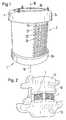
- a container 1 according to the inventionis during a surgical procedure that is performed on the spine Patients are made as stiffening and spacing Element implanted between vertebrae. Before implanting, the basket-like container 1 filled with bone tissue that the patient at one taken elsewhere.
- the recording volume for the Bone tissueis located within an axis 10 arranged wall 2.
- This peripheral wall 2 - in the form of a grid, Fabric or braid -is composed, for example, of wires 21, 22, which are crossed at tie points 20.
- the wires 21 of a first familyare aligned axially parallel; the remaining wires 22, which are a second family form, are directed transversely to those of the first group. Between the wires 21, 22 relatively large openings 23 are provided.
- the Connection of all wires 21, 22should have a sufficient support function, so that - to be able to create a tight packing - the bone tissue in the receiving volume can be pressed into it.
- the x-ray optical inspectionallows for follow-up examinations an implantation the regenerative progress of the contained in the container 1 Monitor tissue.
- the wall 2is on an edge of rings running transversely to the axis 10 3a and 3b limited. On these rings tips 4 are arranged, which at Implanting allows anchoring in the vertebrae to be treated.
- the upper ring 3acontains an opening 30 through which the bone tissue in the recording volume can be filled.
- the lower ring 3bcan also have a corresponding opening.
- the container 1has an advantage on the lower ring 3b a bottom made of the same wire structure as that Wall 2 can be formed.
- Fig. 2shows a first lumbar vertebra 11 of a spine, which means two containers 1 according to the invention with a second lumbar vertebra 12 connected is. On the vertebrae 11 and 12 can to 13 wells for the Form container 1, bone tissue must be removed.
- the rings 3a and 3bwhich in the embodiment according to FIG. 1 are parallel to are arranged one another, can also be designed as shown in FIG. 3 is shown, namely so that the transverse to the axis 10 Outside of the rings 3a and 3b lie on levels 31a and 31b, which one Include angle ⁇ .
- containers 1 according to FIG. 3can be used be used for surgical treatments of lordosis in the In the area of the lumbar spine.
- the wall 2can - see Fig. 4 - simply from a flat wire mesh be made by forming this fabric into a cylinder and a Overlap strips is welded into a seam 25.
- a flat wire meshis shaped such that two chambers and two seams 25 are formed.
- An inner wall 24acts as a reinforcement of the peripheral wall 2.
- Fig. 5bAnother bicameral Embodiment is shown in Fig. 5b. Here are two pipe sections 2 'and 2 " joined together along a flat wall 24 '.
- the container 1 according to the inventioncan also be used as longer tubes are offered, the walls 2 are formed so that they on a required length can be cut to size.
- the rings 3a and 3b as well as the wall 2are provided as separate parts, which according to let the wall 2 be cut together.
- FIGS. 4, 5a and 5bWalls 2 made from flat pieces of fabric. But it is also possible to design the wall 2 as a spatial wattle.
- FIG. 6shown as the left half of a longitudinal section through the container 1.
- vertical Wires 21connect an input ring 3 located at the top in an arc shape a disc 5 arranged at the bottom 6 of the container 1 and thereby form a wall 2 widening downwards and part of the bottom 6.
- Wires 22are braided in transverse to the wires 21.
- the wires 22can closed rings with different diameters; you can but also form a coherent piece that is helical is braided between the wires 21.
- anchoring tips 4At the entrance ring 3 and at the Base plate 5 are anchoring tips 4 attached.
- the openings 23are so large that the X-ray optics according to the invention Viewing across the axis 10 is possible.
- FIG. 6Another example a seamless wall 2 is shown in FIG. 7.
- FIG. 7Another example a seamless wall 2 is shown in FIG. 7.
- Between seventeen (Odd number) vertical wires 21form braided wires 22 ' Double rings as shown in Fig. 8 for an embodiment with only seven vertical wires 21 is illustrated. So that such a seamless Embodiment is possible, the number of vertical wires 21 to be odd. 9 with two double rings 22 ' it is illustrated that the openings 23 in the wall 2 have different sizes can be trained.
- the wires 21 of the first familyhave a larger diameter than that other wires 22 so that - in conjunction with the wires of the second Coulter - can withstand a greater force in the direction of axis 10.
- All metals suitable for implantsin particular, can be used as material Titanium, or suitable alloys can be used.
- Part of the walls 2, which is formed, for example, by individual wires 22,can also be non-metallic and, for example, from absorbable material consist.
- the cross section of the container 1 according to the inventiondoes not have to be necessarily be circular.
- the wall 2can, for example, the shape of a square or hexagon.
- the inventive Container -if appropriate shaped - for surgery on bones used to substitute tissue, for example, due to of a cancerous tumor had to be removed.
Landscapes
- Health & Medical Sciences (AREA)
- Engineering & Computer Science (AREA)
- Biomedical Technology (AREA)
- Transplantation (AREA)
- Orthopedic Medicine & Surgery (AREA)
- Vascular Medicine (AREA)
- Oral & Maxillofacial Surgery (AREA)
- Heart & Thoracic Surgery (AREA)
- Cardiology (AREA)
- Life Sciences & Earth Sciences (AREA)
- Animal Behavior & Ethology (AREA)
- General Health & Medical Sciences (AREA)
- Public Health (AREA)
- Veterinary Medicine (AREA)
- Neurology (AREA)
- Prostheses (AREA)
Abstract
Description
Translated fromGermanDie Erfindung betrifft einen korbartigen Behälter zum Implantieren vonKnochengewebe gemäss Oberbegriff von Anspruch 1.The invention relates to a basket-like container for implantingBone tissue according to the preamble of
Es ist bekannt, chirurgische Eingriffe an Wirbelsäulen durchzuführen, umdefekte Bandscheiben durch Implantate zu ersetzen. Mit solchen Implantaten,die Abstandhalteelemente zwischen Wirbeln bilden, werden benachbarteWirbel steif verbunden. Es ist auch bekannt, einem PatientenKnochengewebe zu entnehmen, um dieses zu Rekonstruktionszwecken aneiner anderen Stelle zu implantieren, wo das Gewebe dank seinerregenerativen Kräfte zu einem steifen Körper zusammenwächst. BeiWirbelsäulen ist es vorteilhaft, wenn die genannten Abstandhalteelementezumindest teilweise mit Knochengewebe hergestellt werden, wobei sichdessen regenerativen Kräfte nutzen lassen.It is known to perform surgery on spine in order toreplace defective intervertebral discs with implants. With such implants,the spacing elements between vertebrae form neighboring onesVertebrae rigidly connected. It is also known to a patientTo remove bone tissue in order to use this for reconstruction purposesto implant another place where the tissue thanks to itsregenerative forces grow together into a rigid body. AtSpine, it is advantageous if the spacer elements mentionedbe made at least partially with bone tissue, wherebylet its regenerative powers be used.
Aufgabe der Erfindung ist es, ein Implantat zu schaffen, mit demKnochengewebe eines Patienten in oder zwischen Knochen des Patientenimplantierbar ist. Ausserdem muss ein Diagnoseverfahren realisierbar sein,mit dem ein Fortschritt einer Knochengewebebildung kontrollierbar ist. DieseAufgabe wird durch den im Anspruch 1 definierten Behälter gelöst.The object of the invention is to provide an implant with whichA patient's bone tissue in or between the patient's bonesis implantable. In addition, a diagnostic procedure must be feasiblewith which a progress of bone tissue formation can be controlled. ThisThe object is achieved by the container defined in
Der korbartige Behälter enthält ein Aufnahmevolumen für Knochengewebe.Nach einem Einfüllen des Knochengewebes wird der Behälter implantiert.The basket-like container contains a holding volume for bone tissue.After the bone tissue has been filled in, the container is implanted.
Das Aufnahmevolumen befindet sich innerhalb einer um eine Achseangeordneten Wand. Diese periphere Wand besteht aus einem Gitter,Gewebe oder Geflecht. Quer zur Achse ermöglicht die Wand eineröntgenoptische Durchsicht des ungefüllten Aufnahmevolumens. DerFlächenanteil, der für Röntgenstrahlen durchlässig ist, beträgt mindestens30%.The receiving volume is within an axisarranged wall. This peripheral wall consists of a grid,Fabric or braid. The wall enables a transverse to the axisX-ray optical inspection of the unfilled volume. TheThe proportion of area that is permeable to X-rays is at least30%.
Die abhängigen Ansprüche 2 bis 8 betreffen vorteilhafte Ausführungsformendes erfindungsgemässen Behälters. Zwei Verwendungsmöglichkeiten deserfindungsgemässen Behälters sind jeweils Gegenstand der Ansprüche 9 und10.The dependent claims 2 to 8 relate to advantageous embodimentsof the container according to the invention. Two uses of theContainer according to the invention are the subject of claims 9 and10th
Nachfolgend wird die Erfindung anhand der Zeichnungen erläutert. Es zeigen:
- Fig. 1
- eine perspektivische Darstellung eines erfindungsgemässenBehälters,
- Fig. 2
- zwei Wirbel einer Wirbelsäule mit zwischen ihnen angeordnetenBehältern gemäss der Erfindung,
- Fig. 3
- eine zweite Ausführungsform des erfindungsgemässenBehälters,
- Fig. 4
- schematische Querschnitts-Darstellung einer Behälterwand,
- Fig. 5a, 5b
- entsprechende Querschnitte von zweikammerigen Behältern,
- Fig. 6
- eine weitere Ausführungsform des erfindungsgemässenBehälters,
- Fig. 7
- einen Querschnitt durch eine nahtlose Behälterwand,
- Fig. 8
- ein Schrägbild zur Veranschaulichung des Aufbaus dernahtlosen Behälterwand und
- Fig. 9
- eine Seitenansicht von einer Behälterwand mit dem Aufbaugemäss Fig. 8.
- Fig. 1
- 2 shows a perspective illustration of a container according to the invention,
- Fig. 2
- two vertebrae of a spine with containers arranged between them according to the invention,
- Fig. 3
- a second embodiment of the container according to the invention,
- Fig. 4
- schematic cross-sectional representation of a container wall,
- 5a, 5b
- corresponding cross-sections of two-chamber containers,
- Fig. 6
- another embodiment of the container according to the invention,
- Fig. 7
- a cross section through a seamless container wall,
- Fig. 8
- an oblique view to illustrate the structure of the seamless container wall and
- Fig. 9
- 8 shows a side view of a container wall with the structure according to FIG. 8.
Ein erfindungsgemässer Behälter 1, wie er in Fig. 1 perspektivisch dargestelltist, wird bei einem chirurgischen Eingriff, der an der Wirbelsäule einesPatienten vorgenommen wird, als versteifendes und abstandhaltendesElement zwischen Wirbel implantiert. Vor dem Implantieren wird derkorbartige Behälter 1 mit Knochengewebe gefüllt, das dem Patienten an eineranderen Stelle entnommen worden ist. Das Aufnahmevolumen für dasKnochengewebe befindet sich innerhalb einer um eine Achse 10angeordneten Wand 2. Diese periphere Wand 2 - in Form eines Gitters,Gewebes oder Geflechts - ist beispielsweise aus Drähten 21, 22 aufgebaut,die in Bindungspunkten 20 verkreuzt sind. Die Drähte 21 einer ersten Scharsind achsparallel ausgerichtet; die restlichen Drähte 22, die eine zweite Scharbilden, sind zu jenen der ersten Schar quer gerichtet. Zwischen den Drähten21, 22 sind relativ grosse Öffnungen 23 vorgesehen. Diese ermöglichen querzur Achse 10 eine röntgenoptische Durchsicht des ungefülltenAufnahmevolumens, die erfindungsgemäss mindestens 30% beträgt. DerVerbund aller Drähte 21, 22 soll eine ausreichende Stützfunktion ausüben, sodass - um eine dichte Packung erzeugen zu können - das Knochengewebe indas Aufnahmevolumen hineinpressbar ist.A
Die röntgenoptische Durchsicht erlaubt es, bei Kontrolluntersuchungen nacheiner Implantation den regenerativen Fortschritt des im Behälter 1 enthaltenenGewebes zu überwachen.The x-ray optical inspection allows for follow-up examinationsan implantation the regenerative progress of the contained in the
Die Wand 2 ist an einem zur Achse 10 quer verlaufenden Rand von Ringen3a und 3b begrenzt. Auf diesen Ringen sind Spitzen 4 angeordnet, die beimImplantieren eine Verankerung in den zu behandelnden Wirbeln ermöglichen.Der obere Ring 3a enthält eine Öffnung 30, durch die das Knochengewebe indas Aufnahmevolumen eingefüllt werden kann. Auch der untere Ring 3b kanneine entsprechende Öffnung aufweisen. Der Behälter 1 hat jedoch mit Vorteilam unteren Ring 3b einen Boden, der aus der gleichen Drahtstruktur wie dieWand 2 gebildet sein kann.The
Fig. 2 zeigt einen ersten Lendenwirbel 11 einer Wirbelsäule, der mittelszweier Behälter 1 gemäss der Erfindung mit einem zweiten Lendenwirbel 12verbunden ist. An den Wirbeln 11 und 12 kann, um Vertiefungen 13 für dieBehälter 1 auszubilden, Knochengewebe entnommen sein.Fig. 2 shows a first
Die Ringe 3a und 3b, die bei der Ausführungsform gemäss Fig. 1 parallel zueinander angeordnet sind, können auch so ausgebildet sein, wie es in Fig. 3dargestellt ist, nämlich so, dass die quer zur Achse 10 stehendenAussenseiten der Ringe 3a und 3b auf Ebenen 31a und 31b liegen, die einenWinkel δ einschliessen. Bei chirurgischen Behandlungen von Lordose imBereich der Lendenwirbelsäule können Behälter 1 gemäss der Fig. 3eingesetzt werden.The
Die Wand 2 kann - siehe Fig. 4 - einfach aus einem flachen Drahtgewebehergestellt werden, indem dieses Gewebe zu einem Zylinder geformt und einÜberlappungsstreifen zu einer Naht 25 verschweisst wird. Bei derAusführungsform der Fig. 5a ist ein flaches Drahtgewebe derart geformt, dasszwei Kammern sowie zwei Nähte 25 gebildet werden. Eine innere Wand 24wirkt als Verstärkung der peripheren Wand 2. Eine andere zweikammerigeAusführungsform ist in Fig. 5b dargestellt. Hier sind zwei Rohrstücke 2' und 2"entlang einer ebenen Wand 24' zusammengefügt.The
Die erfindungsgemässen Behälter 1 können auch als längere Rohreangeboten werden, deren Wände 2 so ausgebildet sind, dass sie auf eineerforderliche Länge zurecht geschnitten werden können. Dabei sind die Ringe3a und 3b sowie die Wand 2 als separate Teile vorgesehen, die sich nachdem Zurechtschneiden der Wand 2 zusammenfügen lassen.The
Bei den Ausführungsformen gemäss den Figuren 4, 5a und 5b sind dieWände 2 aus flachen Gewebestücken hergestellt. Es ist aber auch möglich,die Wand 2 als räumliches Flechtwerk auszubilden. Ein Beispiel ist in Fig. 6als linke Hälfte eines Längsschnitts durch den Behälter 1 dargestellt. VertikaleDrähte 21 verbinden bogenförmig einen oben liegenden Eingangsring 3 miteiner am Boden 6 des Behälters 1 angeordneten Scheibe 5 und bilden dabeieine nach unten sich erweiternde Wand 2 sowie einen Teil des Bodens 6 aus.Quer zu den Drähten 21 sind Drähte 22 eingeflochten. Die Drähte 22 könnengeschlossene Ringe mit unterschiedlichen Durchmessern sein; sie könnenaber auch ein zusammenhängendes Stück bilden, das schraubenförmigzwischen die Drähte 21 eingeflochten ist. Am Eingangsring 3 und an derBodenscheibe 5 sind Verankerungsspitzen 4 angebracht. Die Öffnungen 23 sind so gross ausgebildet, dass die erfindungsgemässe röntgenoptischeDurchsicht quer zur Achse 10 möglich ist.In the embodiments according to FIGS. 4, 5a and
Der Behälter 1 der Fig. 6 hat eine nahtlose Wand 2. Ein weiteres Beispieleiner nahtlosen Wand 2 ist in Fig. 7 gezeigt. Die zwischen siebzehn(ungerade Anzahl) vertikale Drähte 21 eingeflochtenen Drähte 22' bildenDoppelringe, wie es in Fig. 8 für eine Ausführungsform mit nur siebenvertikalen Drähten 21 veranschaulicht ist. Damit eine solche nahtloseAusführungsform möglich ist, muss die Anzahl der vertikalen Drähten 21ungerade sein. Anhand der Seitenansicht in Fig. 9 mit zwei Doppelringen 22'ist illustriert, dass die Öffnungen 23 in der Wand 2 verschieden grossausgebildet sein können.6 has a
Die Drähte 21 der ersten Schar weisen einen grösseren Durchmesser als dieanderen Drähte 22 auf, damit sie - im Verbund mit den Drähten der zweitenSchar - einer grösseren Kraft in Richtung der Achse 10 standhalten können.Als Material können alle für Implantate geeigneten Metalle, insbesondereTitan, oder geeignete Legierungen verwendet werden. Ein Teil der Wände 2,der beispielsweise durch einzelne der Drähte 22 gebildet wird, kann auchnichtmetallisch sein und beispielsweise aus resorbierbarem Materialbestehen.The
Der Querschnitt des erfindungsgemässen Behälters 1 muss nichtnotwendigerweise kreisförmig sein. Die Wand 2 kann beispielsweise die Formeines Vierkants oder Sechskants haben.The cross section of the
Ausser bei der Behandlung von Wirbelsäulen kann der erfindungsgemässeBehälter - falls geeignet geformt - für einen chirurgischen Eingriff an Knochenverwendet werden, um Gewebe zu substituieren, das beispielsweise aufgrundeines krebsartigen Tumors hat entfernt werden müssen.Except in the treatment of spinal column, the inventiveContainer - if appropriate shaped - for surgery on bonesused to substitute tissue, for example, due toof a cancerous tumor had to be removed.
Claims (10)
Translated fromGermanPriority Applications (1)
| Application Number | Priority Date | Filing Date | Title |
|---|---|---|---|
| EP00810773AEP1088533B1 (en) | 1999-09-28 | 2000-08-29 | Basket-style container for implanting bone tissue |
Applications Claiming Priority (3)
| Application Number | Priority Date | Filing Date | Title |
|---|---|---|---|
| EP99810873 | 1999-09-28 | ||
| EP99810873 | 1999-09-28 | ||
| EP00810773AEP1088533B1 (en) | 1999-09-28 | 2000-08-29 | Basket-style container for implanting bone tissue |
Publications (2)
| Publication Number | Publication Date |
|---|---|
| EP1088533A1true EP1088533A1 (en) | 2001-04-04 |
| EP1088533B1 EP1088533B1 (en) | 2004-11-10 |
Family
ID=8243052
Family Applications (1)
| Application Number | Title | Priority Date | Filing Date |
|---|---|---|---|
| EP00810773AExpired - LifetimeEP1088533B1 (en) | 1999-09-28 | 2000-08-29 | Basket-style container for implanting bone tissue |
Country Status (4)
| Country | Link |
|---|---|
| US (1) | US6447543B1 (en) |
| EP (1) | EP1088533B1 (en) |
| AT (1) | ATE281804T1 (en) |
| DE (1) | DE50008581D1 (en) |
Cited By (3)
| Publication number | Priority date | Publication date | Assignee | Title |
|---|---|---|---|---|
| WO2003068111A1 (en)* | 2002-02-13 | 2003-08-21 | Danfoss A/S | Implant for spine and method for manufacturing same |
| WO2002067824A3 (en)* | 2001-02-28 | 2004-03-11 | Sdgi Holdings Inc | Woven orthopedic implants |
| WO2007038546A1 (en)* | 2005-09-26 | 2007-04-05 | Warsaw Orthopedic, Inc. | Anterior hybrid implant |
Families Citing this family (44)
| Publication number | Priority date | Publication date | Assignee | Title |
|---|---|---|---|---|
| CA2429149C (en)* | 2000-12-15 | 2010-08-24 | Spineology, Inc. | Annulus-reinforcing band |
| US7597715B2 (en) | 2005-04-21 | 2009-10-06 | Biomet Manufacturing Corp. | Method and apparatus for use of porous implants |
| US8123814B2 (en) | 2001-02-23 | 2012-02-28 | Biomet Manufacturing Corp. | Method and appartus for acetabular reconstruction |
| US7527649B1 (en) | 2002-02-15 | 2009-05-05 | Nuvasive, Inc. | Intervertebral implant and related methods |
| US6733533B1 (en)* | 2002-11-19 | 2004-05-11 | Zimmer Technology, Inc. | Artificial spinal disc |
| USD493533S1 (en) | 2003-02-14 | 2004-07-27 | Nuvasive, Inc. | Intervertebral implant |
| EP1605872B1 (en)* | 2003-03-24 | 2009-09-30 | Synthes GmbH | Vertebral disc or intervertebral disc prosthesis |
| US7153325B2 (en)* | 2003-08-01 | 2006-12-26 | Ultra-Kinetics, Inc. | Prosthetic intervertebral disc and methods for using the same |
| US8062365B2 (en)* | 2003-08-04 | 2011-11-22 | Warsaw Orthopedic, Inc. | Bone supporting devices with bio-absorbable end members |
| US20050187631A1 (en)* | 2004-01-27 | 2005-08-25 | Sdgi Holdings, Inc. | Prosthetic device |
| DE102004041354A1 (en)* | 2004-08-25 | 2006-03-30 | Buck, Alfred | Implant for surgical use in humans or vertebrates |
| US8066778B2 (en) | 2005-04-21 | 2011-11-29 | Biomet Manufacturing Corp. | Porous metal cup with cobalt bearing surface |
| US8021432B2 (en) | 2005-12-05 | 2011-09-20 | Biomet Manufacturing Corp. | Apparatus for use of porous implants |
| US8266780B2 (en) | 2005-04-21 | 2012-09-18 | Biomet Manufacturing Corp. | Method and apparatus for use of porous implants |
| US8292967B2 (en) | 2005-04-21 | 2012-10-23 | Biomet Manufacturing Corp. | Method and apparatus for use of porous implants |
| US20070050032A1 (en)* | 2005-09-01 | 2007-03-01 | Spinal Kinetics, Inc. | Prosthetic intervertebral discs |
| US7731753B2 (en)* | 2005-09-01 | 2010-06-08 | Spinal Kinetics, Inc. | Prosthetic intervertebral discs |
| US20070083200A1 (en)* | 2005-09-23 | 2007-04-12 | Gittings Darin C | Spinal stabilization systems and methods |
| US7691105B2 (en)* | 2005-09-26 | 2010-04-06 | Depuy Spine, Inc. | Tissue augmentation, stabilization and regeneration technique |
| CN101272750A (en)* | 2005-09-26 | 2008-09-24 | 华沙整形外科股份有限公司 | Transforaminal hybrid implant |
| CA2623448A1 (en)* | 2005-09-26 | 2007-03-29 | Frank J. Schwab | Hybrid intervertebral spinal fusion implant |
| US20070093906A1 (en)* | 2005-10-26 | 2007-04-26 | Zimmer Spine, Inc. | Nucleus implant and method |
| CA2634514A1 (en)* | 2005-12-23 | 2007-07-12 | Zimmer Gmbh | Coated textiles |
| DE102005061932A1 (en) | 2005-12-23 | 2007-07-05 | Biedermann Motech Gmbh | Placeholder for implantation to the human vertebrae has three tubular bodies having different lengths and diameters that are inserted and connected to each other by pins so that they project over the edges of the next larger tubular body |
| US7645301B2 (en)* | 2006-01-13 | 2010-01-12 | Zimmer Spine, Inc. | Devices and methods for disc replacement |
| US7635447B2 (en) | 2006-02-17 | 2009-12-22 | Biomet Manufacturing Corp. | Method and apparatus for forming porous metal implants |
| US20070276496A1 (en)* | 2006-05-23 | 2007-11-29 | Sdgi Holdings, Inc. | Surgical spacer with shape control |
| ES2395298T3 (en) | 2006-07-14 | 2013-02-11 | Biedermann Technologies Gmbh & Co. Kg | Separator for insertion between two vertebrae |
| US20080021556A1 (en)* | 2006-07-21 | 2008-01-24 | Edie Jason A | Expandable vertebral implant and methods of use |
| US8173551B2 (en)* | 2006-09-07 | 2012-05-08 | Taiwan Semiconductor Manufacturing Co., Ltd. | Defect reduction using aspect ratio trapping |
| US8506636B2 (en) | 2006-09-08 | 2013-08-13 | Theken Spine, Llc | Offset radius lordosis |
| US9278007B2 (en)* | 2006-09-26 | 2016-03-08 | Spinal Kinetics, Inc. | Prosthetic intervertebral discs having cast end plates and methods for making and using them |
| US8403987B2 (en) | 2006-09-27 | 2013-03-26 | Spinal Kinetics Inc. | Prosthetic intervertebral discs having compressible core elements bounded by fiber-containing membranes |
| US9381098B2 (en)* | 2006-09-28 | 2016-07-05 | Spinal Kinetics, Inc. | Tool systems for implanting prosthetic intervertebral discs |
| WO2008130654A1 (en)* | 2007-04-18 | 2008-10-30 | Life Spine, Inc. | Spinal disc prostheses |
| US20120109303A1 (en)* | 2010-10-28 | 2012-05-03 | Warsaw Orthopedic, Inc. | Implant assemblies, devices and methods for providing stabilization between first and second vertebrae |
| US20140222088A1 (en)* | 2011-05-08 | 2014-08-07 | Spinal Ventures, Llc | Implant and Fastener Fixation Devices and Delivery Instrumentation |
| EP2877129B1 (en)* | 2012-07-25 | 2017-10-11 | Spineology, Inc. | Mesh spacer hybrid |
| US9427325B2 (en)* | 2013-07-26 | 2016-08-30 | Warsaw Orthopedic, Inc. | Interbody implant and method |
| CN105496609B (en)* | 2015-12-17 | 2017-12-01 | 北京市春立正达医疗器械股份有限公司 | One kind overhauls titanium net |
| EP3407837B1 (en)* | 2016-01-28 | 2021-07-07 | DePuy Synthes Products, Inc. | Helical bone graft containment cage |
| DE102016003838A1 (en)* | 2016-03-29 | 2017-10-05 | Merete Holding Gmbh | Implantable compensating cuff for an endoprosthesis |
| CN106137474A (en)* | 2016-08-15 | 2016-11-23 | 王琪 | A kind of titanium net anti-sinking pad |
| US10478312B2 (en)* | 2016-10-25 | 2019-11-19 | Institute for Musculoskeletal Science and Education, Ltd. | Implant with protected fusion zones |
Citations (7)
| Publication number | Priority date | Publication date | Assignee | Title |
|---|---|---|---|---|
| US4064567A (en)* | 1976-09-15 | 1977-12-27 | The Sampson Corporation | Prosthesis-to-bone interface system |
| EP0268115A1 (en)* | 1986-11-03 | 1988-05-25 | Lutz Biedermann | Space keeping device, especially for a vertebra |
| WO1994018913A1 (en)* | 1993-02-16 | 1994-09-01 | Henderson Fraser C | Fusion stabilization chamber |
| FR2726994A1 (en)* | 1994-11-17 | 1996-05-24 | Caffiniere Jean Yves De | Fixing cage for fractured upper end of humerus |
| WO1997023175A1 (en)* | 1995-12-21 | 1997-07-03 | Colorado | Interbody vertebral implant |
| WO1998026725A1 (en)* | 1996-12-18 | 1998-06-25 | Eska Implants Gmbh & Co. | Prophylactic implant for protecting bone segments affected by osteoporosis against fractures |
| WO1999032055A1 (en)* | 1997-12-23 | 1999-07-01 | Depuy Acromed, Inc. | Spacer assembly for use in spinal surgeries |
Family Cites Families (3)
| Publication number | Priority date | Publication date | Assignee | Title |
|---|---|---|---|---|
| US4961740B1 (en)* | 1988-10-17 | 1997-01-14 | Surgical Dynamics Inc | V-thread fusion cage and method of fusing a bone joint |
| DE59108588D1 (en)* | 1991-08-07 | 1997-04-10 | Oscobal Ag | Endoprosthesis with a metal wire |
| US5443510A (en)* | 1993-04-06 | 1995-08-22 | Zimmer, Inc. | Porous coated implant and method of making same |
- 2000
- 2000-07-26USUS09/625,596patent/US6447543B1/ennot_activeExpired - Fee Related
- 2000-08-29DEDE50008581Tpatent/DE50008581D1/ennot_activeExpired - Lifetime
- 2000-08-29EPEP00810773Apatent/EP1088533B1/ennot_activeExpired - Lifetime
- 2000-08-29ATAT00810773Tpatent/ATE281804T1/ennot_activeIP Right Cessation
Patent Citations (7)
| Publication number | Priority date | Publication date | Assignee | Title |
|---|---|---|---|---|
| US4064567A (en)* | 1976-09-15 | 1977-12-27 | The Sampson Corporation | Prosthesis-to-bone interface system |
| EP0268115A1 (en)* | 1986-11-03 | 1988-05-25 | Lutz Biedermann | Space keeping device, especially for a vertebra |
| WO1994018913A1 (en)* | 1993-02-16 | 1994-09-01 | Henderson Fraser C | Fusion stabilization chamber |
| FR2726994A1 (en)* | 1994-11-17 | 1996-05-24 | Caffiniere Jean Yves De | Fixing cage for fractured upper end of humerus |
| WO1997023175A1 (en)* | 1995-12-21 | 1997-07-03 | Colorado | Interbody vertebral implant |
| WO1998026725A1 (en)* | 1996-12-18 | 1998-06-25 | Eska Implants Gmbh & Co. | Prophylactic implant for protecting bone segments affected by osteoporosis against fractures |
| WO1999032055A1 (en)* | 1997-12-23 | 1999-07-01 | Depuy Acromed, Inc. | Spacer assembly for use in spinal surgeries |
Cited By (5)
| Publication number | Priority date | Publication date | Assignee | Title |
|---|---|---|---|---|
| WO2002067824A3 (en)* | 2001-02-28 | 2004-03-11 | Sdgi Holdings Inc | Woven orthopedic implants |
| WO2003068111A1 (en)* | 2002-02-13 | 2003-08-21 | Danfoss A/S | Implant for spine and method for manufacturing same |
| JP2005516731A (en)* | 2002-02-13 | 2005-06-09 | ダンフォス アクチーセルスカブ | Spine implant and method for manufacturing the same |
| WO2007038546A1 (en)* | 2005-09-26 | 2007-04-05 | Warsaw Orthopedic, Inc. | Anterior hybrid implant |
| US8764832B2 (en) | 2005-09-26 | 2014-07-01 | Warsaw Orhtopedic, Inc. | Anterior hybrid implant |
Also Published As
| Publication number | Publication date |
|---|---|
| ATE281804T1 (en) | 2004-11-15 |
| US6447543B1 (en) | 2002-09-10 |
| EP1088533B1 (en) | 2004-11-10 |
| DE50008581D1 (en) | 2004-12-16 |
Similar Documents
| Publication | Publication Date | Title |
|---|---|---|
| EP1088533B1 (en) | Basket-style container for implanting bone tissue | |
| DE69837998T2 (en) | SWIVELING FUSION DEVICE WITH A PARTICULARLY CIRCULAR SECTION SHAPING CROSS SECTION SEGMENTS | |
| EP1563809B1 (en) | Intervertebral nucleus prosthesis and surgical procedure for implanting the same. | |
| DE60133033T2 (en) | ANNULATIVE STRENGTHENING BAND | |
| DE69232517T2 (en) | SURGICAL PROSTHETIC SPINE IMPLANT | |
| DE60212648T2 (en) | TRANSPLANT-CONTAINING IMPLANTS FOR LAMINOPLASTY | |
| DE60015955T2 (en) | INTERMEDIATE DISCUSPULPOSUS PROSTHESIS WITH OPTIONAL COUPLABLE BODIES | |
| DE60019643T2 (en) | IMPLANT FROM BONE MATERIAL | |
| DE69630030T2 (en) | ENDOVASCULAR STENT | |
| EP2777629B1 (en) | Spreadable implant for the spinal column. | |
| DE60023284T2 (en) | INTERMEDIATE DISCUSPULPOSUS PROSTHESIS WITH SHAPE CHANGE PROPERTIES | |
| DE69919852T2 (en) | INTERMEDIATE PULSE IMPLANT WITH REDUCED CONTACT AREA AND IMPLANTING PROCEDURE | |
| DE69822817T2 (en) | OPEN INTERMEDIATE DISTANCE PIECE | |
| DE60033790T2 (en) | NUCLEUS RESPONSE TO THE SURGICAL RECONSTRUCTION OF THE BELT, AND TREATMENT METHOD | |
| EP3272315B1 (en) | Instrument for introducing a spinal implant and spinal implant | |
| DE69633756T2 (en) | Spondylodeseimplantate | |
| DE60302032T2 (en) | Artificial disc | |
| DE3781958T2 (en) | PILLOW-SHAPED IMPLANT. | |
| DE69822508T2 (en) | PLACEHOLDER ASSEMBLY FOR USE IN SPINE SURGERY SURGERY | |
| DE60132796T2 (en) | TONGUE DEVICE WITH THREAD FOR FUSIONING BENEFICIAL BONE STRUCTURES | |
| DE60022620T2 (en) | INTERMEDIATE SPACER WITH ACCESSIBLE INTERIOR THROUGH SIDE WALLS | |
| DE60032187T2 (en) | UNIT FOR REPAIRING CARTILES | |
| DE69532528T2 (en) | EXPANDABLE FABRIC IMPLANT FOR STABILIZING THE SPINAL SEGMENT | |
| DE60032264T2 (en) | spinal implant | |
| DE2203242A1 (en) | Vertebral disc prosthesis |
Legal Events
| Date | Code | Title | Description |
|---|---|---|---|
| PUAI | Public reference made under article 153(3) epc to a published international application that has entered the european phase | Free format text:ORIGINAL CODE: 0009012 | |
| AK | Designated contracting states | Kind code of ref document:A1 Designated state(s):AT BE CH CY DE DK ES FI FR GB GR IE IT LI LU MC NL PT SE | |
| AX | Request for extension of the european patent | Free format text:AL;LT;LV;MK;RO;SI | |
| 17P | Request for examination filed | Effective date:20010907 | |
| AKX | Designation fees paid | Free format text:AT BE CH CY DE DK ES FI FR GB GR IE IT LI LU MC NL PT SE | |
| 17Q | First examination report despatched | Effective date:20031007 | |
| GRAP | Despatch of communication of intention to grant a patent | Free format text:ORIGINAL CODE: EPIDOSNIGR1 | |
| RAP1 | Party data changed (applicant data changed or rights of an application transferred) | Owner name:CENTERPULSE ORTHOPEDICS LTD. | |
| GRAS | Grant fee paid | Free format text:ORIGINAL CODE: EPIDOSNIGR3 | |
| GRAA | (expected) grant | Free format text:ORIGINAL CODE: 0009210 | |
| AK | Designated contracting states | Kind code of ref document:B1 Designated state(s):AT BE CH CY DE DK ES FI FR GB GR IE IT LI LU MC NL PT SE | |
| PG25 | Lapsed in a contracting state [announced via postgrant information from national office to epo] | Ref country code:NL Free format text:LAPSE BECAUSE OF FAILURE TO SUBMIT A TRANSLATION OF THE DESCRIPTION OR TO PAY THE FEE WITHIN THE PRESCRIBED TIME-LIMIT Effective date:20041110 Ref country code:ES Free format text:LAPSE BECAUSE OF FAILURE TO SUBMIT A TRANSLATION OF THE DESCRIPTION OR TO PAY THE FEE WITHIN THE PRESCRIBED TIME-LIMIT Effective date:20041110 Ref country code:IE Free format text:LAPSE BECAUSE OF FAILURE TO SUBMIT A TRANSLATION OF THE DESCRIPTION OR TO PAY THE FEE WITHIN THE PRESCRIBED TIME-LIMIT Effective date:20041110 Ref country code:FI Free format text:LAPSE BECAUSE OF FAILURE TO SUBMIT A TRANSLATION OF THE DESCRIPTION OR TO PAY THE FEE WITHIN THE PRESCRIBED TIME-LIMIT Effective date:20041110 | |
| REG | Reference to a national code | Ref country code:GB Ref legal event code:FG4D Free format text:NOT ENGLISH | |
| REG | Reference to a national code | Ref country code:CH Ref legal event code:EP Ref country code:CH Ref legal event code:NV Representative=s name:DR. GRAF & PARTNER INTELLECTUAL PROPERTY | |
| REG | Reference to a national code | Ref country code:IE Ref legal event code:FG4D Free format text:GERMAN | |
| REF | Corresponds to: | Ref document number:50008581 Country of ref document:DE Date of ref document:20041216 Kind code of ref document:P | |
| GBT | Gb: translation of ep patent filed (gb section 77(6)(a)/1977) | Effective date:20050111 | |
| PG25 | Lapsed in a contracting state [announced via postgrant information from national office to epo] | Ref country code:DK Free format text:LAPSE BECAUSE OF FAILURE TO SUBMIT A TRANSLATION OF THE DESCRIPTION OR TO PAY THE FEE WITHIN THE PRESCRIBED TIME-LIMIT Effective date:20050210 Ref country code:GR Free format text:LAPSE BECAUSE OF FAILURE TO SUBMIT A TRANSLATION OF THE DESCRIPTION OR TO PAY THE FEE WITHIN THE PRESCRIBED TIME-LIMIT Effective date:20050210 Ref country code:SE Free format text:LAPSE BECAUSE OF FAILURE TO SUBMIT A TRANSLATION OF THE DESCRIPTION OR TO PAY THE FEE WITHIN THE PRESCRIBED TIME-LIMIT Effective date:20050210 | |
| NLV1 | Nl: lapsed or annulled due to failure to fulfill the requirements of art. 29p and 29m of the patents act | ||
| REG | Reference to a national code | Ref country code:IE Ref legal event code:FD4D | |
| PG25 | Lapsed in a contracting state [announced via postgrant information from national office to epo] | Ref country code:CY Free format text:LAPSE BECAUSE OF FAILURE TO SUBMIT A TRANSLATION OF THE DESCRIPTION OR TO PAY THE FEE WITHIN THE PRESCRIBED TIME-LIMIT Effective date:20050829 | |
| PG25 | Lapsed in a contracting state [announced via postgrant information from national office to epo] | Ref country code:MC Free format text:LAPSE BECAUSE OF NON-PAYMENT OF DUE FEES Effective date:20050831 Ref country code:BE Free format text:LAPSE BECAUSE OF NON-PAYMENT OF DUE FEES Effective date:20050831 Ref country code:LU Free format text:LAPSE BECAUSE OF NON-PAYMENT OF DUE FEES Effective date:20050831 | |
| PLBE | No opposition filed within time limit | Free format text:ORIGINAL CODE: 0009261 | |
| STAA | Information on the status of an ep patent application or granted ep patent | Free format text:STATUS: NO OPPOSITION FILED WITHIN TIME LIMIT | |
| ET | Fr: translation filed | ||
| 26N | No opposition filed | Effective date:20050811 | |
| REG | Reference to a national code | Ref country code:GB Ref legal event code:732E | |
| REG | Reference to a national code | Ref country code:CH Ref legal event code:PUE Owner name:ZIMMER GMBH Free format text:CENTERPULSE ORTHOPEDICS LTD.#ALTGASSE 44#6340 BAAR (CH) -TRANSFER TO- ZIMMER GMBH#SULZER ALLEE 8#8404 WINTERTHUR (CH) | |
| REG | Reference to a national code | Ref country code:FR Ref legal event code:TP | |
| BERE | Be: lapsed | Owner name:*CENTERPULSE ORTHOPEDICS LTD Effective date:20050831 | |
| PG25 | Lapsed in a contracting state [announced via postgrant information from national office to epo] | Ref country code:PT Free format text:LAPSE BECAUSE OF NON-PAYMENT OF DUE FEES Effective date:20050410 | |
| PGFP | Annual fee paid to national office [announced via postgrant information from national office to epo] | Ref country code:AT Payment date:20080814 Year of fee payment:9 | |
| REG | Reference to a national code | Ref country code:CH Ref legal event code:PFA Owner name:ZIMMER GMBH Free format text:ZIMMER GMBH#SULZER ALLEE 8#8404 WINTERTHUR (CH) -TRANSFER TO- ZIMMER GMBH#SULZER ALLEE 8#8404 WINTERTHUR (CH) | |
| PG25 | Lapsed in a contracting state [announced via postgrant information from national office to epo] | Ref country code:AT Free format text:LAPSE BECAUSE OF NON-PAYMENT OF DUE FEES Effective date:20090829 | |
| PGFP | Annual fee paid to national office [announced via postgrant information from national office to epo] | Ref country code:CH Payment date:20110824 Year of fee payment:12 | |
| PGFP | Annual fee paid to national office [announced via postgrant information from national office to epo] | Ref country code:GB Payment date:20110819 Year of fee payment:12 Ref country code:FR Payment date:20110901 Year of fee payment:12 Ref country code:DE Payment date:20110823 Year of fee payment:12 | |
| PGFP | Annual fee paid to national office [announced via postgrant information from national office to epo] | Ref country code:IT Payment date:20110825 Year of fee payment:12 | |
| REG | Reference to a national code | Ref country code:CH Ref legal event code:PL | |
| GBPC | Gb: european patent ceased through non-payment of renewal fee | Effective date:20120829 | |
| PG25 | Lapsed in a contracting state [announced via postgrant information from national office to epo] | Ref country code:LI Free format text:LAPSE BECAUSE OF NON-PAYMENT OF DUE FEES Effective date:20120831 Ref country code:CH Free format text:LAPSE BECAUSE OF NON-PAYMENT OF DUE FEES Effective date:20120831 | |
| REG | Reference to a national code | Ref country code:FR Ref legal event code:ST Effective date:20130430 | |
| PG25 | Lapsed in a contracting state [announced via postgrant information from national office to epo] | Ref country code:IT Free format text:LAPSE BECAUSE OF NON-PAYMENT OF DUE FEES Effective date:20120829 | |
| PG25 | Lapsed in a contracting state [announced via postgrant information from national office to epo] | Ref country code:DE Free format text:LAPSE BECAUSE OF NON-PAYMENT OF DUE FEES Effective date:20130301 Ref country code:GB Free format text:LAPSE BECAUSE OF NON-PAYMENT OF DUE FEES Effective date:20120829 | |
| PG25 | Lapsed in a contracting state [announced via postgrant information from national office to epo] | Ref country code:FR Free format text:LAPSE BECAUSE OF NON-PAYMENT OF DUE FEES Effective date:20120831 | |
| REG | Reference to a national code | Ref country code:DE Ref legal event code:R119 Ref document number:50008581 Country of ref document:DE Effective date:20130301 |