EP1088518A1 - Surgical fixing device - Google Patents
Surgical fixing deviceDownload PDFInfo
- Publication number
- EP1088518A1 EP1088518A1EP00810749AEP00810749AEP1088518A1EP 1088518 A1EP1088518 A1EP 1088518A1EP 00810749 AEP00810749 AEP 00810749AEP 00810749 AEP00810749 AEP 00810749AEP 1088518 A1EP1088518 A1EP 1088518A1
- Authority
- EP
- European Patent Office
- Prior art keywords
- tissue
- tissue holder
- mandrels
- around
- fastening means
- Prior art date
- Legal status (The legal status is an assumption and is not a legal conclusion. Google has not performed a legal analysis and makes no representation as to the accuracy of the status listed.)
- Granted
Links
- 239000004744fabricSubstances0.000claimsdescription7
- 230000007423decreaseEffects0.000claimsdescription6
- 239000000463materialSubstances0.000claimsdescription3
- 229920000747poly(lactic acid)Polymers0.000claimsdescription3
- 210000001519tissueAnatomy0.000description100
- 230000005499meniscusEffects0.000description37
- 239000007943implantSubstances0.000description10
- 238000000034methodMethods0.000description8
- 238000009958sewingMethods0.000description7
- 230000000694effectsEffects0.000description6
- 230000035876healingEffects0.000description6
- 238000003780insertionMethods0.000description4
- 230000037431insertionEffects0.000description4
- 238000011161developmentMethods0.000description3
- 230000003902lesionEffects0.000description3
- 238000001356surgical procedureMethods0.000description3
- 238000013459approachMethods0.000description2
- 230000007480spreadingEffects0.000description2
- 206010072970Meniscus injuryDiseases0.000description1
- 238000004873anchoringMethods0.000description1
- 230000008901benefitEffects0.000description1
- 230000001419dependent effectEffects0.000description1
- 238000013461designMethods0.000description1
- 230000003993interactionEffects0.000description1
- 210000003127kneeAnatomy0.000description1
- 230000001151other effectEffects0.000description1
- 230000004044responseEffects0.000description1
- 238000011477surgical interventionMethods0.000description1
- 210000001258synovial membraneAnatomy0.000description1
- 238000012549trainingMethods0.000description1
Images
Classifications
- A—HUMAN NECESSITIES
- A61—MEDICAL OR VETERINARY SCIENCE; HYGIENE
- A61B—DIAGNOSIS; SURGERY; IDENTIFICATION
- A61B17/00—Surgical instruments, devices or methods
- A61B17/064—Surgical staples, i.e. penetrating the tissue
- A—HUMAN NECESSITIES
- A61—MEDICAL OR VETERINARY SCIENCE; HYGIENE
- A61B—DIAGNOSIS; SURGERY; IDENTIFICATION
- A61B17/00—Surgical instruments, devices or methods
- A61B17/064—Surgical staples, i.e. penetrating the tissue
- A61B2017/0649—Coils or spirals
Definitions
- the inventionrelates to a tissue holder according to the preamble of independent claim.
- Treatment techniqueis fixing the tissue parts by sewing, whereby different sewing techniques are used. Sewing one Meniscus tear and a suitable instrument is for example in WO-A-98/31288. This type of fixation (sewing) the Tissue parts are reliable, but from the surgical technique quite complex, especially if the procedure is done arthroscopically (Accessibility), which is more and more the case in such cases and probably already represents the normal case.
- Another treatment techniqueis the fixation of the tissue parts by Insertion of an implant.
- implantsfor example Pins with barbs on the pin body (first fastener) and with one Projection (second fastener) on the blunt end of the pin body used, as described for example in WO-A-97/18761.
- the barbsget caught in the tissue after insertion beyond the tear, pull this piece of fabric towards the ledge and hold at the blunt end of the pin in this part of the crack the two pieces of tissue in this position so that the tear can heal.
- Other implants used in the fixation of the tissue partsare, for example, screws that have two sections, each with a thread. The two threads (first and second fastening means), however, have a different slope (see e.g.
- tissue holder(implant) propose which is easy to attach to the fabric parts and the Holds tissue parts in a desired position relative to each other.
- this tissue holder for the treatment of cracks in the Meniscusmay be suitable and also for patients in whom the inner Part ("core") of the meniscus is already soft, so you can otherwise on would avoid sewing techniques.
- tissue holdersuch as it is characterized by the features of the independent claim.
- inventive Fabric holdersresult from the dependent claims.
- the first and second fastening means of the Tissue holderin each case at least one curved mandrel, which extends around the longitudinal axis extends around the tissue holder. So even if the tissue holder centrally, that is, into the soft "core” of the meniscus the connection with the two tissue parts using the curved Thorn that extends around the longitudinal axis of the tissue holder, that is not in the "core” of the meniscus, but in an area below the Surface of the meniscus where the meniscus is still firm has to a sufficiently good fixation of the tissue holder to reach.
- the tissue holdercan definitely be in the possibly soft "core" of the meniscus can be inserted because the connection with the tissue is made in one area (below the Surface of the meniscus) where the tissue has sufficient strength has to achieve a good fixation of the tissue holder.
- the means comprising the Spines and thus the tissue partshold relative to each other, one in Connecting web running in the direction of the longitudinal axis of the tissue holder.
- the spikesextend around this connecting web. This is one from the structural design and handling reasonably simple and functional variant of the Tissue holder.
- the axial distance between the Mandrel or the thorns of the first fastener and the mandrel or the Thorns of the second fastener towards the free end of the Thorns towards, i.e. starting from the free end of the thorns to This distancedecreases towards the connecting bridge.
- This causes the Screwing in the tissue holder the tissue parts are pulled togethercan (as desired when treating a tear in the meniscus is) that the tissue holder acts as a clamp.
- the mandrelsextend helical around the longitudinal axis of the tissue holder or around the Connecting bridge around.
- the tissue holderacts as a clamp.
- it is also possiblenamely if the distance between the mandrel or the thorns of the first fastening means and the Spike or spikes of the second fastener towards the free If the end of the mandrels decreases. In the aforementioned treatment of a crack in the This does not apply to the meniscus.
- the axial thicknessis one Mandrel towards the free end of the mandrel. This allows you to Achieve spiral shape and cause that when turning the Tissue holder the two tissue parts are pulled together and the Tissue holder acts as a clamp. Depending on how the axial Thickness decreases, you can also achieve that when turning the Tissue holder the tissue parts are pulled apart, provided this is desired.
- the mandrelsare essentially cylindrical trained, but still they are helical. At the free end the mandrels can naturally rejuvenate in order to penetrate the to facilitate each tissue part. Even with this training can either the function of a clip or the tissue parts are effected can be pulled apart, depending on how the spiral runs.
- the first and second fastenerseach have two mandrels, the mandrels of the respective fastener at opposite locations from the Go out the connecting bridge and then go around in the same direction Extend connecting bridge around.
- an attachment pieceis provided for a tool with which a connection of the tissue holder can be effected on the tissue parts.
- This Approach piececan, for example, a receiving slot for a turning tool (like a screwdriver) or otherwise be designed to the movement of the tissue holder to a tool enable.
- tissue holderfrom one bioresorbable material, in particular made of polylactides. This results in the desired fixation and healing on the one hand, on the other hand, the tissue holder does not have to go through one again surgical intervention are removed.
- the tissue holder 1shows an embodiment of an inventive Tissue holder 1.
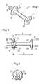
- the tissue holder 1according to the invention has the first Fastening means 2 in the form of two mandrels 21 and 22 and second Fastening means 3 in the form of two mandrels 31 and 32, which with the Tissue parts on both sides and beyond a tear in the meniscus can be connected are (see Fig. 4). Between the first fasteners 2 and second fastening means 3 extends a connecting web 4. Furthermore 1 that the tissue holder is still an extension 5 has for a tool (not shown), with the help of which Tissue holder 1 with the tissue parts (e.g. with the meniscus parts on this side and beyond the crack, see Fig. 4) can be connected.
- the Extension 5can e.g. be provided with a slot 50, as in Fig. 1 and Fig. 2 shown, in which a turning tool according to the principle of a Screwdriver can intervene, but other means can be provided with which a movement of the tissue holder 1 causes can be
- the two mandrels 21 and 22 and 31 and 32each extend in the same Direction around the connecting web 4 and run helically.
- the tissue holder 1 -overall considered - be introduced into the "core" of the meniscus, even if this is already soft and is not a good anchor for such Tissue holder would allow more, because yes the spines in one area engage in the meniscus below the surface of the meniscus, i.e. in an area where the meniscus has sufficient strength to to ensure a good anchorage of the tissue holder.
- the surface of the meniscusremains unaffected by the thorn, what a perfect interaction of the articulation surface of the respective Femoral condyle with the meniscus is important.
- the axial thickness A of the mandrelsalso increases, starting from the connecting web 4 towards the free end of the respective mandrel, which is shown in FIG. 2 can see well.
- the distance a between those facing outwards Surfaces 210 and 220 of the mandrels 21 and 22 of the first fastening means 2 and the corresponding outward-facing surfaces 310 and 320 Thorns 31 and 32 of the second fastening means 3is therefore constant.
- the Distance b between the inwardly facing surfaces 211 and 221 of the Mandrels 21 and 22 of the first fastening means 2 and the corresponding ones inward-facing surfaces 311 and 321 of the mandrels 31 and 32 of the second fastener 3takes however - from the free end of the mandrels viewed in the direction of the connecting bridge 4 - from.
- the mandrelscan be designed so that the Distance between the inward-facing surfaces of the mandrels constant is held and the distance between those facing outwards Areas increases (viewed from the web to the free end) to the Pull pieces of fabric apart and then hold them in this position. A spreading effect can then be achieved in this way.
- the tissue holder 1is made of bioabsorbable Materials, especially made of polylactides. Then can namely the one hand the crack are held together so that the fixation and healing can take place, on the other hand no further operative Intervention to be carried out to the tissue holder 1 again later remove.
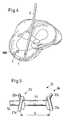
- Fig. 4is indicated schematically how a tissue holder in the case of a Tears T in the inner meniscus MM (meniscus medialis) can.
- Ais already in the area of the front end of the crack T.
- Tissue holder 1introduced. It becomes straight in the area of the rear end brought in.
- a cannula Cis first passed through the tear T. pricked until they just entered the other part of the meniscus is.
- the tissue holder 1becomes through the interior of this cannula C. then with a screwdriver (not shown) that fits into the slot 50 of the Attachment 5 engages (see Fig. 1 and Fig. 2) to the front end of the Cannula C pushed.
- the screwdrivercan be at its distal end have a hole that the actual blade of the Screwdriver surrounds. This bore takes the extension 5 of the Tissue holder on. The blade of the Screwdriver can then in the slot 50 of the extension 5 engage without the blade sliding radially out of the slot 50 can because it is caught in the hole that surrounds the blade. Against axial sliding of the tissue holder 1 out of the bore of the Screwdriver reaches the friction between tissue holder 1 and Screwdriver.
- the tissue parts on both sides of the Cracks Thave already been pretreated so that the edges of the Tissue parts using an arthroscopic rasp or one mechanical shavers have already been machined to the perimeniskale To stimulate synovium to a healing response. Then they can Tissue parts are held together until finally with the help of the cannula C the tissue holder 1 is inserted and then fixed so that the Finally T - with the tissue holder 1 inserted - contracted is like a clamp so that the tear T can heal.
- FIG. 5shows a further exemplary embodiment of an inventive one Tissue holder 1a shown.
- This embodimentpoints like that 1 also first and second Fastening means 2a and 3a, which in turn each have two mandrels 21a, 22a and 31a, 32a, which extend around the connecting web 4a extend.
- the mandrelsare essentially (i.e. except for the approach at the connecting bridge, which is a little thicker and the free end, which is a little pointed) cylindrical shape.
Landscapes
- Health & Medical Sciences (AREA)
- Life Sciences & Earth Sciences (AREA)
- Surgery (AREA)
- Heart & Thoracic Surgery (AREA)
- Engineering & Computer Science (AREA)
- Biomedical Technology (AREA)
- Nuclear Medicine, Radiotherapy & Molecular Imaging (AREA)
- Medical Informatics (AREA)
- Molecular Biology (AREA)
- Animal Behavior & Ethology (AREA)
- General Health & Medical Sciences (AREA)
- Public Health (AREA)
- Veterinary Medicine (AREA)
- Surgical Instruments (AREA)
- Prostheses (AREA)
Abstract
Description
Translated fromGermanDie Erfindung betrifft einen Gewebehalter gemäss dem Oberbegriff desunabhängigen Patentanspruchs.The invention relates to a tissue holder according to the preamble ofindependent claim.
Bei Läsionen von Gewebe möchte man im Normalfall einen möglichst gutenund schnellen Heilungsprozess erreichen. Dies gilt insbesondere auch fürLäsionen des Meniskus des Knies, speziell für kleine Risse im Meniskus.Solche Meniskusläsionen heilen beim erwachsenen Menschen nicht spontan,sondern die Gewebeteile müssen zu diesem Zweck gegeneinander gedrücktund fixiert werden. Nur eine ausreichendes Zusammendrücken derGewebeteile gegeneinander erlaubt einen Heilungsprozess. Angestrebt wirdnach dem Heilen eine möglichst glatte Oberfläche des Meniskus ohneKratzer etc,. weil auf dieser Meniskusoberfläche ja die Femurkondylen gleitenund die Artikulationsflächen der Kondylen knorpelig und daher sehrempfindlich für Kratzer in der Meniskusoberfläche sind.In the case of tissue lesions, you usually want the best possibleand achieve fast healing process. This applies in particular toLesions of the knee meniscus, especially for small tears in the meniscus.Such meniscal lesions do not heal spontaneously in adult humans,but the tissue parts must be pressed against each other for this purposeand be fixed. Just squeeze theTissue parts against each other allow a healing process. The aim isafter healing a smooth surface of the meniscus withoutScratches etc ,. because the femoral condyles slide on this meniscus surfaceand the articular surfaces of the condyles are cartilaginous and therefore veryare sensitive to scratches in the meniscus surface.
Um eine ausreichendes Zusammendrücken der Gewebeteile gegeneinanderzu bewirken und die Gewebeteile dann in dieser Position zu halten, habensich verschiedene Behandlungstechniken etabliert. Eine solcheBehandlungstechnik ist das Fixieren der Gewebeteile durch Nähen, wobeiunterschiedlichste Nähtechniken zum Einsatz kommen. Das Nähen eines Meniskusrisses und ein hierfür geeignetes Instrument ist beispielsweise inder WO-A-98/31288 beschrieben. Diese Art der Fixierung (Nähen) derGewebeteile ist zwar zuverlässig, aber von der Operationstechnik herziemlich aufwendig, erst recht dann, wenn der Eingriff arthroskopisch erfolgt(Zugänglichkeit), was in solchen Fällen mehr und mehr der Fall ist und wohlschon den Regelfall darstellt.To compress the tissue parts sufficiently against each othereffect and then hold the tissue parts in this positiondifferent treatment techniques are established. SuchTreatment technique is fixing the tissue parts by sewing, wherebydifferent sewing techniques are used. Sewing oneMeniscus tear and a suitable instrument is for example inWO-A-98/31288. This type of fixation (sewing) theTissue parts are reliable, but from the surgical techniquequite complex, especially if the procedure is done arthroscopically(Accessibility), which is more and more the case in such cases and probablyalready represents the normal case.
Eine weitere Behandlungstechnik ist das Fixieren der Gewebeteile durchEinbringen eines Implantats. Als Implantate werden dabei beispielsweiseStifte mit Widerhaken am Stiftkörper (erste Befestigungsmittel) und mit einemVorsprung (zweite Befestigungsmittel) am stumpfen Ende des Stiftkörpersverwendet, wie dies beispielsweise in der WO-A-97/18761 beschrieben ist.Die Widerhaken verhaken sich nach dem Einbringen in dem Gewebeteiljenseits des Risses, ziehen dieses Gewebeteil in Richtung auf den Vorsprungam stumpfen Ende des Stifts in dem diesseitigen Teil des Risses und haltendie beiden Gewebeteile in dieser Position, sodass der Riss heilen kann.Andere Implantate, welche bei der Fixierung der Gewebeteile verwendetwerden, sind beispielsweise Schrauben, welche zwei Abschnitte aufweisen,die jeweils mit einem Gewinde versehen sind. Die beiden Gewinde (erste undzweite Befestigungsmittel) weisen jedoch eine unterschiedliche Steigung auf(siehe z.B. US-A-5,569,252). Durch diese unterschiedliche Steigung derGewinde wird dann, wenn das eine Gewinde jenseits des Risses und dasandere Gewinde diesseits des Risses im Meniskus greifen, die beidenGewebeteile zusammengezogen und in dieser Position gehalten, sodass derRiss heilen kann.Another treatment technique is the fixation of the tissue parts byInsertion of an implant. As implants, for examplePins with barbs on the pin body (first fastener) and with oneProjection (second fastener) on the blunt end of the pin bodyused, as described for example in WO-A-97/18761.The barbs get caught in the tissue after insertionbeyond the tear, pull this piece of fabric towards the ledgeand hold at the blunt end of the pin in this part of the crackthe two pieces of tissue in this position so that the tear can heal.Other implants used in the fixation of the tissue partsare, for example, screws that have two sections,each with a thread. The two threads (first andsecond fastening means), however, have a different slope(see e.g. US-A-5,569,252). Due to this different slope of theThread becomes when there is a thread beyond the crack and thatgrasp other threads on this side of the tear in the meniscus, the twoTissue parts pulled together and held in this position so that theCan heal crack.
Bei diesen Arten des Fixierens der Gewebeteile mit Hilfe von Implantatenwird das Implantat (der Stift mit den Widerhaken bzw. die Schraube) in Bezugauf die Dicke des Meniskus jeweils zentral, d.h. ungefähr in die Mitte,eingebracht. Wichtig ist jedenfalls, dass von dem Implantat absolut nichts in die Meniskusoberfläche vorsteht, denn auf dieser müssen ja dieFemurkondylen gleiten. Diese Arten der Fixierung (mittels Implantaten) sindvon der Operationstechnik her einfacher als die Nähtechniken. Mitzunehmendem Alter der Patienten wird es aber schwieriger, diese Art derFixierung einzusetzen, weil der innere Teil ("Kern") des Meniskus zunehmendmukoid wird, also weich, sodass die Implantate im Innern ("Kern") desMeniskus nur noch schlecht fixiert werden können. Es wird dann vermehrt aufdie bereits beschriebenen, von der Operationstechnik her jedochvergleichsweise aufwendigen, Nähtechniken ausgewichen, weil die zentraleVerankerung des Implantats (im "Kern" des Meniskus) nicht mehr in Fragekommt.With these types of fixation of the tissue parts with the help of implantsthe implant (the pin with the barbs or the screw) in relationcentral to the thickness of the meniscus, i.e. about in the middle,brought in. In any case, it is important that there is absolutely nothing in the implantthe meniscus surface protrudes, because they have to be on itGlide the femoral condyles. These types of fixation (using implants) arethe surgical technique is simpler than the sewing technique. WithAs the age of the patient increases, this type ofUse fixation because the inner part ("core") of the meniscus is increasingmucoid becomes soft, so that the implants inside ("core") of theMeniscus can only be fixed poorly. It then increasesthose already described, but from the surgical techniquecomparatively complex, sewing techniques avoided because the centralAnchoring the implant (in the "core" of the meniscus) is no longer an optionis coming.
Es ist daher eine Aufgabe der Erfindung, einen Gewebehalter (Implantat)vorzuschlagen, welcher einfach an den Gewebeteilen befestigbar ist und dieGewebeteile in einer gewünschten Position relativ zueinander hält.Insbesondere soll dieser Gewebehalter für die Behandlung von Rissen imMeniskus geeignet sein und zwar auch für Patienten, bei denen der innereTeil ("Kern") des Meniskus schon weich ist, sodass man sonst aufNähtechniken ausweichen würde.It is therefore an object of the invention to provide a tissue holder (implant)propose which is easy to attach to the fabric parts and theHolds tissue parts in a desired position relative to each other.In particular, this tissue holder for the treatment of cracks in theMeniscus may be suitable and also for patients in whom the innerPart ("core") of the meniscus is already soft, so you can otherwise onWould avoid sewing techniques.
Diese Aufgabe wird erfindungsgemäss durch einen Gewebehalter gelöst, wieer durch die Merkmale des unabhängigen Patentanspruchs charakterisiert ist.Besonders vorteilhafte Ausgestaltungen des erfindungsgemässenGewebehalters ergeben sich aus den abhängigen Patentansprüchen.According to the invention, this object is achieved by a tissue holder, such asit is characterized by the features of the independent claim.Particularly advantageous embodiments of the inventiveFabric holders result from the dependent claims.
Insbesondere umfassen die ersten und zweiten Befestigungsmittel desGewebehalters (die Befestigungsmittel diesseits und jenseits des Risses)jeweils mindestens einen gekrümmten Dorn, welcher sich um die Längsachsedes Gewebehalters herum erstreckt. Selbst wenn also der Gewebehalterzentral, also in den weichen "Kern" des Meniskus eingebracht wird, erfolgt die Verbindung mit den beiden Gewebeteilen mit Hilfe des gekrümmtenDorns, der sich um die Längsachse des Gewebehalters herum erstreckt, alsonicht im "Kern" des Meniskus, sondern in einem Bereich unterhalb derOberfläche des Meniskus, wo der Meniskus noch genügend Festigkeitaufweist, um eine ausreichend gute Fixierung des Gewebehalters zuerreichen. Der Gewebehalter kann also - gesamthaft betrachtet - durchaus inden möglicherweise weichen "Kern" des Meniskus eingebracht werden, weildie Verbindung mit dem Gewebe eben in einem Bereich erfolgt (unterhalb derOberfläche des Meniskus), wo das Gewebe eine ausreichende Festigkeitaufweist, um eine gute Fixierung des Gewebehalters zu erreichen.In particular, the first and second fastening means of theTissue holder (the fasteners on both sides and beyond the tear)in each case at least one curved mandrel, which extends around the longitudinal axisextends around the tissue holder. So even if the tissue holdercentrally, that is, into the soft "core" of the meniscusthe connection with the two tissue parts using the curvedThorn that extends around the longitudinal axis of the tissue holder, that isnot in the "core" of the meniscus, but in an area below theSurface of the meniscus where the meniscus is still firmhas to a sufficiently good fixation of the tissue holderto reach. Viewed as a whole, the tissue holder can definitely be inthe possibly soft "core" of the meniscus can be inserted becausethe connection with the tissue is made in one area (below theSurface of the meniscus) where the tissue has sufficient strengthhas to achieve a good fixation of the tissue holder.
Bei einem vorteilhaften Ausführungsbeispiel umfassen die Mittel, welche dieDorne und damit die Gewebeteile relativ zueinander halten, einen inRichtung der Längsachse des Gewebehalters verlaufenden Verbindungssteg.Die Dorne erstrecken sich dabei um diesen Verbindungssteg herum. Dies isteine von der konstruktiven Ausgestaltung und vom Handling hereinigermassen einfache und funktionstüchtige Ausführungsvariante desGewebehalters.In an advantageous embodiment, the means comprising theSpines and thus the tissue parts hold relative to each other, one inConnecting web running in the direction of the longitudinal axis of the tissue holder.The spikes extend around this connecting web. This isone from the structural design and handlingreasonably simple and functional variant of theTissue holder.
Bei einer vorteilhaften Weiterbildung nimmt der axiale Abstand zwischen demDorn bzw. den Dornen der ersten Befestigungsmittel und dem Dorn bzw. denDornen der zweiten Befestigungsmittel in Richtung zum freien Ende derDorne hin zu, also vom freien Ende der Dorne ausgehend zumVerbindungssteg hin nimmt dieser Abstand ab. Dies bewirkt, dass beimEindrehen des Gewebehalters die Gewebeteile zusammengezogen werdenkönnen (wie dies bei der Behandlung eines Risses im Meniskus erwünschtist), dass also der Gewebehalter als Klammer wirkt.In an advantageous development, the axial distance between theMandrel or the thorns of the first fastener and the mandrel or theThorns of the second fastener towards the free end of theThorns towards, i.e. starting from the free end of the thorns toThis distance decreases towards the connecting bridge. This causes theScrewing in the tissue holder the tissue parts are pulled togethercan (as desired when treating a tear in the meniscusis) that the tissue holder acts as a clamp.
Bei einem vorteilhaften Ausführungsbeispiel erstrecken sich die Dornewendelförmig um die Längsachse des Gewebehalters bzw. um den Verbindungssteg herum. Durch diesen wendelförmigen Verlauf kann manerreichen, dass beim Eindrehen des Gewebehalters die beiden Gewebeteilezusammengezogen werden und der Gewebehalter als Klammer wirkt.Grundsätzlich ist es jedoch auch möglich (nämlich dann, wenn der Abstandzwischen dem Dorn bzw. den Dornen der ersten Befestigungsmittel und demDorn bzw. den Dornen der zweiten Befestigungsmittel in Richtung zum freienEnde der Dorne hin abnimmt) die Gewebeteile auseinanderzuziehen, soferndie erwünscht ist. Bei der vorgenannten Behandlung eines Risses imMeniskus trifft dies allerdings nicht zu.In an advantageous embodiment, the mandrels extendhelical around the longitudinal axis of the tissue holder or around theConnecting bridge around. Through this helical course you canachieve that when the tissue holder is screwed in, the two tissue partsare pulled together and the tissue holder acts as a clamp.In principle, however, it is also possible (namely if the distancebetween the mandrel or the thorns of the first fastening means and theSpike or spikes of the second fastener towards the freeIf the end of the mandrels decreases)that is desired. In the aforementioned treatment of a crack in theThis does not apply to the meniscus.
Bei einer Weiterbildung dieses Gewebehalters nimmt die axiale Dicke einesDorns in Richtung zum freien Ende des Dorns hin ab. Dadurch kann man dieWendelform erreichen und bewirken, dass beim Eindrehen desGewebehalters die beiden Gewebeteile zusammengezogen werden und derGewebehalter als Klammer wirkt. Je nachdem, auf welche Weise die axialeDicke abnimmt, kann man auch erreichen, dass beim Eindrehen desGewebehalters die Gewebeteile auseinandergezogen werden, sofern dieserwünscht ist.In a further development of this tissue holder, the axial thickness is oneMandrel towards the free end of the mandrel. This allows you toAchieve spiral shape and cause that when turning theTissue holder the two tissue parts are pulled together and theTissue holder acts as a clamp. Depending on how the axialThickness decreases, you can also achieve that when turning theTissue holder the tissue parts are pulled apart, provided thisis desired.
Bei einer anderen Weiterbildung sind die Dorne im wesentlichen zylindrischausgebildet, aber dennoch verlaufen sie wendelförmig. Am freien Endekönnen sich die Dorne natürlich verjüngen, um das Eindringen in dasjeweilige Gewebeteil zu erleichtern. Auch mit dieser Weiterbildung kannentweder die Funktion einer Klammer bewirkt werden oder die Gewebeteilekönnen auseinander gezogen werden, je nachdem, wie die Wendel verläuft.In another development, the mandrels are essentially cylindricaltrained, but still they are helical. At the free endthe mandrels can naturally rejuvenate in order to penetrate theto facilitate each tissue part. Even with this training caneither the function of a clip or the tissue parts are effectedcan be pulled apart, depending on how the spiral runs.
Bei einem weiteren Ausführungsbeispiel des Gewebehalters umfassen dieersten und zweiten Befestigungsmittel jeweils zwei Dorne, wobei die Dornedes jeweiligen Befestigungsmittels an gegenüberliegenden Orten von demVerbindungssteg ausgehen und sich dann in gleicher Richtung um den Verbindungssteg herum erstrecken. Dies hat den Vorteil, dass beimEinbringen des Gewebhalters der Gewebehalter selbst in ungünstigen Fällennicht sehr weit gedreht werden muss, bis ein Dorn in das jeweiligeGewebeteil einsticht und somit mit dem jeweiligen Gewebeteil verbunden ist.In a further embodiment of the tissue holder, thefirst and second fasteners each have two mandrels, the mandrelsof the respective fastener at opposite locations from theGo out the connecting bridge and then go around in the same directionExtend connecting bridge around. This has the advantage that whenInserting the tissue holder of the tissue holder even in unfavorable casesdoes not have to be turned very far until a thorn in the respectiveTissue part pierces and is thus connected to the respective tissue part.
Bei einem weiteren vorteilhaften Ausführungsbeispiel ist am Gewebehalterein Ansatzstück für ein Werkzeug vorgesehen, mit welchem eine Verbindungdes Gewebehalters an den Gewebeteilen bewirkt werden kann. DiesesAnsatzstück kann beispielsweise ein Aufnahmeschlitz für ein Drehwerkzeug(nach Art eine Schraubendrehers) aufweisen oder aber auch andersausgebildet sein, um einem Werkzeug die Bewegung des Gewebehalters zuermöglichen.In a further advantageous embodiment is on the tissue holderan attachment piece is provided for a tool with which a connectionof the tissue holder can be effected on the tissue parts. ThisApproach piece can, for example, a receiving slot for a turning tool(like a screwdriver) or otherwisebe designed to the movement of the tissue holder to a toolenable.
Schliesslich ist es vorteilhaft, wenn der Gewebehalter aus einembioresorbierbaren Material, insbesondere aus Polylactiden, hergestellt ist.Dadurch erfolgt einerseits die gewünschte Fixierung und Heilung,andererseits muss der Gewebehalter nicht noch einmal durch einenoperativen Eingrif entfernt werden.Finally, it is advantageous if the tissue holder from onebioresorbable material, in particular made of polylactides.This results in the desired fixation and healing on the one hand,on the other hand, the tissue holder does not have to go through one againsurgical intervention are removed.
Im folgenden wird die Erfindung anhand der Zeichnung näher erläutert. Dabeizeigen in schematischer Darstellung und/oder teilweise im Schnitt:
- Fig. 1
- eine perspektivische Ansicht eines Ausführungsbeispiels eineserfindungsgemässen Gewebehalters,
- Fig. 2
- eine Seitenansicht des Gewebehalters nach Fig. 1,
- Fig. 3
- eine Stirnansicht des Gewebehalters nach Fig. 1 aus der Richtungdes Ansatzstücks,
- Fig. 4
- eine schematische Darstellung zur Erläuterung des Einbringens desGewebehalters bei der Behandlung eines Risses im Innenmeniskus(meniscus medialis)
- Fig. 5
- ein weiteres Ausführungsbeispiel eines erfindungsgemässenGewebehalters in Seitenansicht.
- Fig. 1
- 2 shows a perspective view of an exemplary embodiment of a tissue holder according to the invention,
- Fig. 2
- 2 shows a side view of the tissue holder according to FIG. 1,
- Fig. 3
- 1 from the direction of the end piece,
- Fig. 4
- a schematic representation to explain the insertion of the tissue holder in the treatment of a tear in the inner meniscus (meniscus medialis)
- Fig. 5
- a further embodiment of a tissue holder according to the invention in side view.
In Fig. 1 erkennt man ein Ausführungsbeispiel eines erfindungsgemässenGewebehalters 1. Der erfindungsgemässe Gewebehalter 1 weist ersteBefestigungsmittel 2 in Form der zwei Dorne 21 und 22 auf sowie zweiteBefestigungsmittel 3 in Form der zwei Dorne 31 und 32, welche mit denGewebeteilen diesseits und jenseits eines Risses im Meniskus verbindbarsind (siehe Fig. 4). Zwischen den ersten Befestigungsmitteln 2 und denzweiten Befestigungsmitteln 3 erstreckt sich ein Verbindungssteg 4. Fernererkennt man in Fig. 1, dass der Gewebehalter noch ein Ansatzstück 5aufweist für ein Werkzeug (nicht dargestellt), mit dessen Hilfe derGewebehalter 1 mit den Gewebeteilen (z.B. mit den Meniskusteilen diesseitsund jenseits des Risses, siehe Fig. 4) verbunden werden kann. DasAnsatzstück 5 kann z.B. mit einem Schlitz 50 versehen sein, wie in Fig. 1 undFig. 2 gezeigt, in welchen ein Drehwerkzeug nach dem Prinzip einesSchraubendrehers eingreifen kann, es können aber auch andere Mittelvorgesehen sein, mit denen eine Bewegung des Gewebehalters 1 bewirktwerden kann.1 shows an embodiment of an
Aus Fig. 1 und Fig. 2 erkennt man, dass die Dorne 21 und 22 der erstenBefestigungsmittel 2 bzw. die Dorne 31 und 32 der zweitenBefestigungsmittel 3 gekrümmt sind und sich jeweils ausgehend von dem Verbindungssteg 4 um den Verbindungssteg 4 herum erstrecken. In Fig. 3erkennt man, dass sich die Dorne 21 und 22 (entsprechendes gilt für dieDorne 31 und 32) wendelförmig um den Verbindungssteg 4 herumerstrecken. Grundsätzlich würde es ausreichen, wenn die erstenBefestigungsmittel 2 und die zweiten Befestigungsmittel 3 jeweils nur einenDorn aufweisen würden, das gezeigte Ausführungsbeispiel mit jeweils zweiDornen, die an gegenüberliegenden Orten von dem Verbindungssteg 4ausgehen, also etwa um 180° auf dem Umfang des Verbindungsstegs 4versetzt sind, ist jedoch insofern vorteilhaft, als der Gewebehalter 1 beimEinbringen nicht erst um einen grossen Winkel gedreht werden muss,sondern schnell in das jeweilige Gewebeteil einsticht. Die beiden Dorne 21und 22 sowie 31 und 32 erstrecken sich dabei jeweils in der gleichenRichtung um den Verbindungssteg 4 herum und verlaufen wendelförmig.1 and 2 show that the
Dadurch dass sich die Dorne 21 und 22 sowie 31 und 32 um denVerbindungssteg 4 herum erstrecken, kann der Gewebehalter 1 - gesamthaftbetrachtet - in den "Kern" des Meniskus eingebracht werden, auch wenndieser bereits weich ist und keine gute Verankerung für einen derartigenGewebhalter mehr ermöglichen würde, weil ja die Dorne in einem Bereichunterhalb der Oberfläche des Meniskus in den Meniskus eingreifen, also ineinem Bereich, wo der Meniskus eine ausreichende Festigkeit aufweist, umeine gute Verankerung des Gewebehalters zu gewährleisten. Gleichzeitigbleibt die Oberfläche des Meniskus von dem Dorn unbeeinträchtigt, was fürein einwandfreies Zusammenwirken der Artikulationsfläche der jeweiligenFemurkondyle mit dem Meniskus wichtig ist.Because the
In Fig. 3 erkennt man gut, dass die radiale Dicke R der Dorne 21 und 22(entsprechendes gilt für die Dorne 31 und 32) ausgehend vomVerbindungssteg 4 in Richtung zum freien Ende des jeweiligen Dorns hinabnimmt. Dies begründet einerseits eine stabile Befestigung der Dorne am Verbindungssteg 4, andererseits müssen die Dorne am freien Endeeinigermassen spitz sein, damit sie in die Gewebeteile (hier: Meniskusteile)eindringen können. Dabei kann der Dorn am freien Ende - wie in Fig. 3gezeigt, leicht über die tangentiale Richtung hinweg nach aussen stehen,sodass beim Eindrehen der Dorn in jedem Fall in das betreffende Gewebeteileinsticht und nicht etwa unter dem Gewebeteil hindurchrutschen kann.3 clearly shows that the radial thickness R of the
Auch die axiale Dicke A der Dorne nimmt ausgehend vom Verbindungssteg 4in Richtung zum freien Ende des jeweiligen Dorns hin ab, was man in Fig. 2gut erkennen kann. Dies gilt beim vorliegenden Ausführungsbeispiel sowohlfür die Dorne 21 und 22 der ersten Befestigungsmittel 2 als auch für dieDorne 31 und 32 der zweiten Befestigungsmittel 3. Dabei verlaufen diejeweiligen in axialer Richtung nach aussen weisenden Flächen der Dorne 21und 22 der ersten Befestigungsmittel 2 und die nach aussen weisendenFlächen der Dorne 31 und 32 der zweiten Befestigungsmittel 3 in in einerEbene senkrecht zur axialen Richtung, also senkrecht zur Längsachse desVerbindungsstegs 4. Der Abstand a zwischen den nach aussen weisendenFlächen 210 bzw. 220 der Dorne 21 und 22 der ersten Befestigungsmittel 2und den entsprechenden nach aussen weisenden Flächen 310 bzw. 320Dornen 31 und 32 der zweiten Befestigungsmittel 3 ist also konstant. DerAbstand b zwischen den nach innen weisenden Flächen 211 bzw. 221 derDorne 21 und 22 der ersten Befestigungsmittel 2 und den entsprechendennach innen weisenden Flächen 311 bzw. 321 der Dorne 31 und 32 derzweiten Befestigungsmittel 3 nimmt jedoch - vom freien Ende der Dorneausgehend in Richtung zum Verbindungssteg 4 betrachtet - ab. Dies führt zuder Wendelform und bewirkt, dass beim Einbringen des Gewebehalters 1 diebeiden Gewebeteile beim Eindrehen des Gewebehalters 1zusammengezogen werden und somit die Wirkung einer Klammer erzielen.Im Grunde würde es zur Erzielung dieser Klammerwirkung ausreichen, wennnur die ersten Befestigungsmittel 2 oder nur die zweiten Befestigungsmitteln 3 Dorne aufweisen würden, deren nach innen weisende Flächen soausgebildet sind wie oben beschrieben. Dadurch, dass dies aber bei beidenBefestigungsmitteln der Fall ist, wird die Klammerwirkung noch verstärkt.The axial thickness A of the mandrels also increases, starting from the connecting web 4towards the free end of the respective mandrel, which is shown in FIG. 2can see well. This applies both in the present exemplary embodimentfor the
Es ist leicht einzusehen, dass dann, wenn es erwünscht ist, Gewebeteileauseinanderzuziehen, die Dorne so ausgebildet sein können, dass derAbstand zwischen den nach innen weisenden Flächen der Dorne konstantgehalten wird und der Abstand zwischen den nach aussen weisendenFlächen zunimmt (vom Steg zum freien Ende hin betrachtet), um dieGewebeteile auseinanderzuziehen und sie dann in dieser Position zu halten.Auf diese Weise kann dann eine Spreizwirkung erzielt werden.It is easy to see that when it is desired, tissue partspull apart, the mandrels can be designed so that theDistance between the inward-facing surfaces of the mandrels constantis held and the distance between those facing outwardsAreas increases (viewed from the web to the free end) to thePull pieces of fabric apart and then hold them in this position.A spreading effect can then be achieved in this way.
Besonders vorteilhaft ist es, wenn der Gewebehalter 1 aus bioresorbierbarenMaterialien, insbesondere aus Polylactiden, hergestellt ist. Dann kannnämlich einerseits der Riss zusammengehalten werden, sodass die Fixierungund Heilung erfolgten kann, andererseits muss kein weiterer operativerEingriff durchgeführt werden, um den Gewebehalter 1 später wieder zuentfernen.It is particularly advantageous if the
In Fig. 4 ist schematisch angedeutet, wie ein Gewebehalter im Falle einesRisses T im Innenmeniskus MM (meniscus medialis) eingebracht werdenkann. Im Bereich des vorderen Endes des Risses T ist bereits einGewebehalter 1 eingebracht. Im Bereich des hinteren Endes wird er geradeeingebracht. Hierzu wird zunächst eine Kanüle C durch den Riss T hindurchgestochen, bis sie gerade eben in den anderen Meniskusteil eingedrungenist. Durch den Innenraum dieser Kanüle C hindurch wird der Gewebhalter 1dann mit einem Schraubendreher (nicht dargestellt), der in den Schlitz 50 desAnsatzstücks 5 eingreift (siehe Fig. 1 und Fig. 2), bis zum vorderen Ende derKanüle C geschoben. Der Schraubendreher kann an seinem distalen Endeeine Bohrung aufweisen, welche die eigentliche Klinge des Schraubendrehers umgibt. Diese Bohrung nimmt das Ansatzstück 5 desGewebehalters auf. Die von der Bohrung umgebene Klinge desSchraubendrehers kann dann in den Schlitz 50 des Ansatzstücks 5eingreifen, ohne dass die Klinge radial aus dem Schlitz 50 herausgleitenkann, weil sie in der Bohrung gefangen ist, die die Klinge umgibt. Gegenaxiales Herausgleiten des Gewebehalters 1 aus der Bohrung desSchraubendrehers reicht die Reibung zwischen Gewebehalter 1 undSchraubendreher aus.In Fig. 4 is indicated schematically how a tissue holder in the case of aTears T in the inner meniscus MM (meniscus medialis)can. A is already in the area of the front end of the crack
Ist nun die Kanüle C durch den Riss T hindurch gerade eben bis in denanderen Meniskusteil eingedrungen, so wird der Schraubendreher mit demGewebehalter 1 in der Kanüle C bis ans distale Ende der Kanülevorgeschoben. Dann wird die Kanüle C ein kleines Stück zurückgezogen.Anschliessend wird der Gewebehalter 1 mit Hilfe des Schraubendrehersgedreht. Die Dorne 21 bzw. 22 und 31 bzw. 32 dringen dann in das diesseitsdes Risses T und das jenseits des Risses T angeordnete Gewebeteil ein, unddurch ein weiteres Drehen (z.B. maximal 1/4-Drehung) des Gewebehalterswerden die Gewebeteile zusammengezogen und auf diese Weise der Riss Tgeschlossen.Is the cannula C through the crack T straight to thepenetrated the other part of the meniscus, the screwdriver with the
Vor dem Einführen der Kanüle C können die Gewebeteile beidseitig desRisses T schon derart vorbehandelt worden sein, dass die Kanten derGewebteile mit Hilfe einer arthroskopischen Raspel bzw. einesmechanischen Shavers bereits bearbeitet worden sind, um das perimeniskaleSynovium zu einer Heilungsantwort zu stimulieren. Sodann können dieGewebeteile zusammengehalten werden, bis schliesslich mit Hilfe der KanüleC der Gewebehalter 1 eingebracht und anschliessend fixiert wird, sodass derRiss T schliesslich - bei eingebrachtem Gewebehalter 1 - zusammengezogenwird nach Art einer Klammer, so dass der Riss T heilen kann.Before inserting the cannula C, the tissue parts on both sides of theCracks T have already been pretreated so that the edges of theTissue parts using an arthroscopic rasp or onemechanical shavers have already been machined to the perimeniskaleTo stimulate synovium to a healing response. Then they canTissue parts are held together until finally with the help of the cannulaC the
In Fig. 5 ist ein weiteres Ausführungsbeispiel eines erfindungsgemässenGewebehalters 1a gezeigt. Dieses Ausführungsbeispiel weist wie dasAusführungsbeispiel gemäss Fig. 1 ebenfalls erste und zweiteBefestigungsmittel 2a und 3a auf, welche ihrerseits jeweils zwei Dorne21a,22a bzw. 31a,32a aufweisen, die sich um den Verbindungssteg 4a herumerstrecken. Anders als bei dem zuvor beschriebenen Ausführungsbeispieldes Gewebehalters sind die Dorne hier jedoch im wesentlichen (d.h.ausgenommen sind der Ansatz am Verbindungssteg, der ein wenig dickerausgebildet ist sowie das freie Ende, welches ein wenig spitz zuläuft)zylinderförmig ausgebildet. Sie verlaufen aber dennoch wendelförmig, undzwar in Richtung voneinander weg, wenn man die Dorne 21a,22a,31a,32ader ersten und zweiten Befestigungsmittel 2a und 3a relativ zueinenanderbetrachtet und sie in Richtung zu ihrem freien Ende hin verfolgt. Dadurchwird der Abstand b zwischen den nach innen weisenden Flächen der Dorne21a,31a bzw. 22a,32a kleiner, wenn man vom freien Ende her betrachtet demVerlauf der Dorne in Richtung zum Verbindungssteg 4a folgt. Auf dieseWeise kann man ebenfalls beim Eindrehen die zuvor anhand des anderenAusführungsbeispiels beschriebene Klammerwirkung erzielen. DasEindrehen des Gewebehalters 1a kann analog verfolgen wie obenbeschrieben, zu diesem Zweck ist ebenfalls ein Ansaztstück 5a bei dembeschriebenen Ausführungsbeispiel vorgesehen. Durch eine Umkehrung deswendelförmigen Verlaufs der Dorne 21a,22a bzw. 31a,32a auf die jeweiligenDorne des anderen Befestigungsmittels zu (wieder in Richtung zum freienEnde des jeweiligen Dorns hin betrachtet), könnte man, so es erwünscht ist,eine Spreizwirkung erzielen, also ein Auseinanderziehen der Gewebteile.5 shows a further exemplary embodiment of an inventive oneTissue holder 1a shown. This embodiment points like that1 also first and secondFastening means 2a and 3a, which in turn each have two
Claims (9)
Translated fromGermanPriority Applications (1)
| Application Number | Priority Date | Filing Date | Title |
|---|---|---|---|
| EP20000810749EP1088518B1 (en) | 1999-09-29 | 2000-08-23 | Surgical fixing device |
Applications Claiming Priority (3)
| Application Number | Priority Date | Filing Date | Title |
|---|---|---|---|
| EP99810880 | 1999-09-29 | ||
| EP99810880 | 1999-09-29 | ||
| EP20000810749EP1088518B1 (en) | 1999-09-29 | 2000-08-23 | Surgical fixing device |
Publications (2)
| Publication Number | Publication Date |
|---|---|
| EP1088518A1true EP1088518A1 (en) | 2001-04-04 |
| EP1088518B1 EP1088518B1 (en) | 2005-06-29 |
Family
ID=26073989
Family Applications (1)
| Application Number | Title | Priority Date | Filing Date |
|---|---|---|---|
| EP20000810749Expired - LifetimeEP1088518B1 (en) | 1999-09-29 | 2000-08-23 | Surgical fixing device |
Country Status (1)
| Country | Link |
|---|---|
| EP (1) | EP1088518B1 (en) |
Cited By (1)
| Publication number | Priority date | Publication date | Assignee | Title |
|---|---|---|---|---|
| WO2006037399A1 (en)* | 2004-10-01 | 2006-04-13 | Ethicon Gmbh | Surgical hook-shaped staple |
Citations (8)
| Publication number | Priority date | Publication date | Assignee | Title |
|---|---|---|---|---|
| FR2719993A1 (en)* | 1994-05-20 | 1995-11-24 | Yves Leclerc | Fixing for prosthetic hernia patch |
| US5474557A (en)* | 1993-09-21 | 1995-12-12 | Mai; Christian | Multibranch osteosynthesis clip with dynamic compression and self-retention |
| US5569252A (en) | 1994-09-27 | 1996-10-29 | Justin; Daniel F. | Device for repairing a meniscal tear in a knee and method |
| WO1997018761A1 (en) | 1995-11-17 | 1997-05-29 | Innovasive Devices, Inc. | Surgical fastening system and method for using the same |
| US5810851A (en)* | 1996-03-05 | 1998-09-22 | Yoon; Inbae | Suture spring device |
| WO1999001071A1 (en)* | 1997-07-02 | 1999-01-14 | Bionx Implants Oy | Surgical fastener for tissue treatment |
| EP0913123A1 (en)* | 1997-10-29 | 1999-05-06 | Arthrex Inc | Meniscal repair device |
| US5957940A (en)* | 1997-06-30 | 1999-09-28 | Eva Corporation | Fasteners for use in the surgical repair of aneurysms |
- 2000
- 2000-08-23EPEP20000810749patent/EP1088518B1/ennot_activeExpired - Lifetime
Patent Citations (8)
| Publication number | Priority date | Publication date | Assignee | Title |
|---|---|---|---|---|
| US5474557A (en)* | 1993-09-21 | 1995-12-12 | Mai; Christian | Multibranch osteosynthesis clip with dynamic compression and self-retention |
| FR2719993A1 (en)* | 1994-05-20 | 1995-11-24 | Yves Leclerc | Fixing for prosthetic hernia patch |
| US5569252A (en) | 1994-09-27 | 1996-10-29 | Justin; Daniel F. | Device for repairing a meniscal tear in a knee and method |
| WO1997018761A1 (en) | 1995-11-17 | 1997-05-29 | Innovasive Devices, Inc. | Surgical fastening system and method for using the same |
| US5810851A (en)* | 1996-03-05 | 1998-09-22 | Yoon; Inbae | Suture spring device |
| US5957940A (en)* | 1997-06-30 | 1999-09-28 | Eva Corporation | Fasteners for use in the surgical repair of aneurysms |
| WO1999001071A1 (en)* | 1997-07-02 | 1999-01-14 | Bionx Implants Oy | Surgical fastener for tissue treatment |
| EP0913123A1 (en)* | 1997-10-29 | 1999-05-06 | Arthrex Inc | Meniscal repair device |
Cited By (1)
| Publication number | Priority date | Publication date | Assignee | Title |
|---|---|---|---|---|
| WO2006037399A1 (en)* | 2004-10-01 | 2006-04-13 | Ethicon Gmbh | Surgical hook-shaped staple |
Also Published As
| Publication number | Publication date |
|---|---|
| EP1088518B1 (en) | 2005-06-29 |
Similar Documents
| Publication | Publication Date | Title |
|---|---|---|
| DE69631473T2 (en) | SOFT TISSUE ANCHOR | |
| DE3855610T2 (en) | TISSUE FIXING DEVICE | |
| DE69115302T2 (en) | Intramedullary hip screw | |
| DE69814889T2 (en) | DEVICE AND METHOD FOR ANCHORING A THREADED ELEMENT ON A WORKPIECE | |
| DE69705489T2 (en) | Surgical clip | |
| DE3541597C2 (en) | ||
| DE69525806T4 (en) | Spreiznähfadenanker | |
| DE3752049T2 (en) | Modular system for fixing the femur | |
| DE69934267T2 (en) | Repositionable suture anchor for surgical suture | |
| DE69431597T2 (en) | SURGICAL SCREW AND DISC | |
| DE69532080T2 (en) | BOLTS FOR SAFEGUARDING IN A BOREOILLOCH | |
| DE69520244T2 (en) | Anchor for sewing thread | |
| EP1082063B1 (en) | Surgical blind rivets with closing elements | |
| DE69527667T2 (en) | Two-part barbed sewing thread anchor | |
| DE69430772T2 (en) | Surgical fastener | |
| DE69930582T2 (en) | Device for securing a transplant in a bone tunnel | |
| DE69021133T2 (en) | Intramedullary nail with self-locking end for the treatment of metadiaphysial fractures of long bones. | |
| DE69903094T2 (en) | clamping device | |
| DE3407084A1 (en) | DEVICE FOR SETTING SURGICAL CLASPS | |
| DE69900545T2 (en) | ABSORBABLE FASTENING CLAMP FOR A PROSTHESIS | |
| DE20101791U1 (en) | Implant | |
| WO2006103598A1 (en) | Device for fixing a ligament | |
| EP0270704A1 (en) | Anchoring element for fastening an osteosynthesis plate to a bone | |
| EP1098600A1 (en) | Fixing element for bone fragments | |
| EP1935352A1 (en) | Device for guiding a drill tool in order to create a second drill hole in a bone |
Legal Events
| Date | Code | Title | Description |
|---|---|---|---|
| PUAI | Public reference made under article 153(3) epc to a published international application that has entered the european phase | Free format text:ORIGINAL CODE: 0009012 | |
| AK | Designated contracting states | Kind code of ref document:A1 Designated state(s):AT BE CH CY DE DK ES FI FR GB GR IE IT LI LU MC NL PT SE | |
| AX | Request for extension of the european patent | Free format text:AL;LT;LV;MK;RO;SI | |
| 17P | Request for examination filed | Effective date:20010907 | |
| AKX | Designation fees paid | Free format text:AT BE CH CY DE DK ES FI FR GB GR IE IT LI LU MC NL PT SE | |
| GRAP | Despatch of communication of intention to grant a patent | Free format text:ORIGINAL CODE: EPIDOSNIGR1 | |
| RAP1 | Party data changed (applicant data changed or rights of an application transferred) | Owner name:ZIMMER GMBH | |
| GRAS | Grant fee paid | Free format text:ORIGINAL CODE: EPIDOSNIGR3 | |
| GRAA | (expected) grant | Free format text:ORIGINAL CODE: 0009210 | |
| AK | Designated contracting states | Kind code of ref document:B1 Designated state(s):AT BE CH CY DE DK ES FI FR GB GR IE IT LI LU MC NL PT SE | |
| PG25 | Lapsed in a contracting state [announced via postgrant information from national office to epo] | Ref country code:FI Free format text:LAPSE BECAUSE OF FAILURE TO SUBMIT A TRANSLATION OF THE DESCRIPTION OR TO PAY THE FEE WITHIN THE PRESCRIBED TIME-LIMIT Effective date:20050629 Ref country code:IE Free format text:LAPSE BECAUSE OF FAILURE TO SUBMIT A TRANSLATION OF THE DESCRIPTION OR TO PAY THE FEE WITHIN THE PRESCRIBED TIME-LIMIT Effective date:20050629 | |
| REG | Reference to a national code | Ref country code:GB Ref legal event code:FG4D Free format text:NOT ENGLISH | |
| REG | Reference to a national code | Ref country code:CH Ref legal event code:EP | |
| REG | Reference to a national code | Ref country code:SE Ref legal event code:TRGR | |
| REG | Reference to a national code | Ref country code:CH Ref legal event code:NV Representative=s name:DR. GRAF & PARTNER INTELLECTUAL PROPERTY | |
| REF | Corresponds to: | Ref document number:50010629 Country of ref document:DE Date of ref document:20050804 Kind code of ref document:P | |
| REG | Reference to a national code | Ref country code:IE Ref legal event code:FG4D Free format text:LANGUAGE OF EP DOCUMENT: GERMAN | |
| PG25 | Lapsed in a contracting state [announced via postgrant information from national office to epo] | Ref country code:LU Free format text:LAPSE BECAUSE OF NON-PAYMENT OF DUE FEES Effective date:20050823 Ref country code:CY Free format text:LAPSE BECAUSE OF FAILURE TO SUBMIT A TRANSLATION OF THE DESCRIPTION OR TO PAY THE FEE WITHIN THE PRESCRIBED TIME-LIMIT Effective date:20050823 | |
| PG25 | Lapsed in a contracting state [announced via postgrant information from national office to epo] | Ref country code:MC Free format text:LAPSE BECAUSE OF NON-PAYMENT OF DUE FEES Effective date:20050831 | |
| GBT | Gb: translation of ep patent filed (gb section 77(6)(a)/1977) | Effective date:20050824 | |
| PG25 | Lapsed in a contracting state [announced via postgrant information from national office to epo] | Ref country code:GR Free format text:LAPSE BECAUSE OF FAILURE TO SUBMIT A TRANSLATION OF THE DESCRIPTION OR TO PAY THE FEE WITHIN THE PRESCRIBED TIME-LIMIT Effective date:20050929 Ref country code:DK Free format text:LAPSE BECAUSE OF FAILURE TO SUBMIT A TRANSLATION OF THE DESCRIPTION OR TO PAY THE FEE WITHIN THE PRESCRIBED TIME-LIMIT Effective date:20050929 | |
| PG25 | Lapsed in a contracting state [announced via postgrant information from national office to epo] | Ref country code:PT Free format text:LAPSE BECAUSE OF FAILURE TO SUBMIT A TRANSLATION OF THE DESCRIPTION OR TO PAY THE FEE WITHIN THE PRESCRIBED TIME-LIMIT Effective date:20051207 | |
| REG | Reference to a national code | Ref country code:ES Ref legal event code:FG2A Ref document number:2244402 Country of ref document:ES Kind code of ref document:T3 | |
| REG | Reference to a national code | Ref country code:IE Ref legal event code:FD4D | |
| ET | Fr: translation filed | ||
| PLBE | No opposition filed within time limit | Free format text:ORIGINAL CODE: 0009261 | |
| STAA | Information on the status of an ep patent application or granted ep patent | Free format text:STATUS: NO OPPOSITION FILED WITHIN TIME LIMIT | |
| 26N | No opposition filed | Effective date:20060330 | |
| PGFP | Annual fee paid to national office [announced via postgrant information from national office to epo] | Ref country code:NL Payment date:20080824 Year of fee payment:9 | |
| PGFP | Annual fee paid to national office [announced via postgrant information from national office to epo] | Ref country code:AT Payment date:20080801 Year of fee payment:9 | |
| PGFP | Annual fee paid to national office [announced via postgrant information from national office to epo] | Ref country code:BE Payment date:20080922 Year of fee payment:9 Ref country code:SE Payment date:20080827 Year of fee payment:9 | |
| BERE | Be: lapsed | Owner name:*ZIMMER G.M.B.H. Effective date:20090831 | |
| REG | Reference to a national code | Ref country code:NL Ref legal event code:V1 Effective date:20100301 | |
| REG | Reference to a national code | Ref country code:CH Ref legal event code:PFA Owner name:ZIMMER GMBH Free format text:ZIMMER GMBH#SULZER ALLEE 8#8404 WINTERTHUR (CH) -TRANSFER TO- ZIMMER GMBH#SULZER ALLEE 8#8404 WINTERTHUR (CH) | |
| PG25 | Lapsed in a contracting state [announced via postgrant information from national office to epo] | Ref country code:BE Free format text:LAPSE BECAUSE OF NON-PAYMENT OF DUE FEES Effective date:20090831 Ref country code:AT Free format text:LAPSE BECAUSE OF NON-PAYMENT OF DUE FEES Effective date:20090823 | |
| PG25 | Lapsed in a contracting state [announced via postgrant information from national office to epo] | Ref country code:NL Free format text:LAPSE BECAUSE OF NON-PAYMENT OF DUE FEES Effective date:20100301 | |
| PGFP | Annual fee paid to national office [announced via postgrant information from national office to epo] | Ref country code:ES Payment date:20100805 Year of fee payment:11 Ref country code:CH Payment date:20100726 Year of fee payment:11 | |
| PGFP | Annual fee paid to national office [announced via postgrant information from national office to epo] | Ref country code:DE Payment date:20100831 Year of fee payment:11 Ref country code:FR Payment date:20100819 Year of fee payment:11 Ref country code:IT Payment date:20100812 Year of fee payment:11 | |
| PGFP | Annual fee paid to national office [announced via postgrant information from national office to epo] | Ref country code:GB Payment date:20100708 Year of fee payment:11 | |
| PG25 | Lapsed in a contracting state [announced via postgrant information from national office to epo] | Ref country code:SE Free format text:LAPSE BECAUSE OF NON-PAYMENT OF DUE FEES Effective date:20090824 | |
| REG | Reference to a national code | Ref country code:CH Ref legal event code:PL | |
| GBPC | Gb: european patent ceased through non-payment of renewal fee | Effective date:20110823 | |
| PG25 | Lapsed in a contracting state [announced via postgrant information from national office to epo] | Ref country code:LI Free format text:LAPSE BECAUSE OF NON-PAYMENT OF DUE FEES Effective date:20110831 Ref country code:CH Free format text:LAPSE BECAUSE OF NON-PAYMENT OF DUE FEES Effective date:20110831 | |
| REG | Reference to a national code | Ref country code:FR Ref legal event code:ST Effective date:20120430 | |
| PG25 | Lapsed in a contracting state [announced via postgrant information from national office to epo] | Ref country code:IT Free format text:LAPSE BECAUSE OF NON-PAYMENT OF DUE FEES Effective date:20110823 | |
| REG | Reference to a national code | Ref country code:DE Ref legal event code:R119 Ref document number:50010629 Country of ref document:DE Effective date:20120301 | |
| PG25 | Lapsed in a contracting state [announced via postgrant information from national office to epo] | Ref country code:GB Free format text:LAPSE BECAUSE OF NON-PAYMENT OF DUE FEES Effective date:20110823 Ref country code:FR Free format text:LAPSE BECAUSE OF NON-PAYMENT OF DUE FEES Effective date:20110831 | |
| PG25 | Lapsed in a contracting state [announced via postgrant information from national office to epo] | Ref country code:DE Free format text:LAPSE BECAUSE OF NON-PAYMENT OF DUE FEES Effective date:20120301 | |
| REG | Reference to a national code | Ref country code:ES Ref legal event code:FD2A Effective date:20130821 | |
| PG25 | Lapsed in a contracting state [announced via postgrant information from national office to epo] | Ref country code:ES Free format text:LAPSE BECAUSE OF NON-PAYMENT OF DUE FEES Effective date:20110824 |