EP1087819B1 - Evoke response detector, averaging the value of the amplitude of the picked up electrode signal - Google Patents
Evoke response detector, averaging the value of the amplitude of the picked up electrode signalDownload PDFInfo
- Publication number
- EP1087819B1 EP1087819B1EP99931681AEP99931681AEP1087819B1EP 1087819 B1EP1087819 B1EP 1087819B1EP 99931681 AEP99931681 AEP 99931681AEP 99931681 AEP99931681 AEP 99931681AEP 1087819 B1EP1087819 B1EP 1087819B1
- Authority
- EP
- European Patent Office
- Prior art keywords
- heart
- evoked response
- signal
- respiration
- heart stimulator
- Prior art date
- Legal status (The legal status is an assumption and is not a legal conclusion. Google has not performed a legal analysis and makes no representation as to the accuracy of the status listed.)
- Expired - Lifetime
Links
- 230000004044responseEffects0.000titleclaimsdescription25
- 238000012935AveragingMethods0.000titleclaimsdescription8
- 230000029058respiratory gaseous exchangeEffects0.000claimsdescription28
- 230000000763evoking effectEffects0.000claimsdescription24
- 206010047289Ventricular extrasystolesDiseases0.000claimsdescription16
- 230000000638stimulationEffects0.000claimsdescription14
- 238000005070samplingMethods0.000claimsdescription3
- 238000002474experimental methodMethods0.000description8
- 238000001514detection methodMethods0.000description6
- 238000010586diagramMethods0.000description5
- 238000000034methodMethods0.000description5
- 208000033986Device capturing issueDiseases0.000description4
- 230000006870functionEffects0.000description4
- 238000000718qrs complexMethods0.000description4
- 238000005259measurementMethods0.000description3
- 230000009471actionEffects0.000description2
- 238000004458analytical methodMethods0.000description2
- 239000003990capacitorSubstances0.000description2
- 230000001965increasing effectEffects0.000description2
- 230000003213activating effectEffects0.000description1
- 230000008901benefitEffects0.000description1
- 238000004364calculation methodMethods0.000description1
- 210000004903cardiac systemAnatomy0.000description1
- 230000003111delayed effectEffects0.000description1
- 230000001419dependent effectEffects0.000description1
- 238000005265energy consumptionMethods0.000description1
- 238000011156evaluationMethods0.000description1
- 238000001914filtrationMethods0.000description1
- 238000004519manufacturing processMethods0.000description1
- 230000034225regulation of ventricular cardiomyocyte membrane depolarizationEffects0.000description1
- 230000004936stimulating effectEffects0.000description1
- 238000012795verificationMethods0.000description1
Images


Classifications
- A—HUMAN NECESSITIES
- A61—MEDICAL OR VETERINARY SCIENCE; HYGIENE
- A61N—ELECTROTHERAPY; MAGNETOTHERAPY; RADIATION THERAPY; ULTRASOUND THERAPY
- A61N1/00—Electrotherapy; Circuits therefor
- A61N1/18—Applying electric currents by contact electrodes
- A61N1/32—Applying electric currents by contact electrodes alternating or intermittent currents
- A61N1/36—Applying electric currents by contact electrodes alternating or intermittent currents for stimulation
- A61N1/362—Heart stimulators
- A61N1/37—Monitoring; Protecting
- A61N1/371—Capture, i.e. successful stimulation
Definitions
- an automatic threshold search functiona so called AUTOCAPTURETM function
- AUTOCAPTURETM functionis used to maintain the energy of the stimulation pulses at a level just above that which is needed to effectuate capture, cf. e.g. US-A-5,458,623.
- a reliable detection of the evoked response, which then is necessary,is, however, not a simple matter, especially when it is desired to sense the evoked response with the same electrode as the one delivering the stimulation pulse and in particular if the sensing is performed by a unipolar electrode configuration.
- fusion beatscreate a big problem for the AUTOCAPTURETM function since these beats often are not detected as heart beats. Instead the heart stimulator in question interprets the evoked response as a loss of capture and as a consequence a backup pulse is issued and the stimulation pulse amplitude is increased. After several such undetected fusion beats the heart stimulator will be in a high output mode, where it remains until the next threshold search is performed. This misinterpretation by the heart stimulator of the evoked response signal will, of course, increase the current drain and decrease the lifetime of the battery and the AUTOCAPTURETM function will be disabled for some time.
- EP-A1-0 836 867a heart stimulating device for avoiding fusion beats is disclosed.
- a control meansis then activating a non-filtered sensing means before the end of a basic escape interval and is prolonging this escape interval by a predetermined length if the non-filtered sensing means senses a QRS complex, such that the corresponding filtered signal, which is delayed due to the filtering procedure, has time to reach the control means for safe verification of the sensed QRS complex.
- a heart pacemakerincluding a pulse generator and a circuitry for measuring a respiration signal of a patient and a control unit for controlling the pulse generator by changing the pulse repetition rate dependent on the respiration signal.
- a series of heart action signalsare acquired by e.g. a QRS-detector.
- the amplitudes (R-waves) of the heart action signalsare subject to fluctuations caused by the respiration cycle of the user of the heart pacemaker.
- the respiration measurementis undertaken by measuring, for each QRS-complex, the distance between the most positive point and the most negative point of the complex, whereas the distance variation between consecutive measurements being a measure of the respiration of the patientAccording to this known device two separate points of the QRS-complex must be identified and determined, this is achieved by a peak sensing means including sample and hold circuits.
- US-A-5 391 192is disclosed a clinical programming system for use with an implanted cardiac system to automatically determine the minimum energy required to evoke a ventricular depolarization. Evoked response is detected through evaluation of the integral of R-waves provided by a surface electrocardiogram. US-A-5 391 192 makes no attempt to differentiate between fusion beats and true captured beats.
- the purpose of the present inventionis to provide an improved evoked response detector for a heart stimulator which makes reliable detection of fusion beats for a unipolar sensing electrode configuration.
- An additional purpose of the present inventionis to provide, in addition to the fusion beat detection, a possibility to determine the respiration rate of the patient from the detected signal.
- said measuring meansis adapted to determine the DC level of the measured electrode signals and subtract this DC level from each sample, whereupon said averaging means is adapted to form the average value of said samples from said evoked response time window to form said average value of the amplitude of the measured electrode signals. It is important to subtract the DC level from the measured electrode signal to get a corrected electrode signal for a subsequent analysis.
- a respiration signal determining meansis arranged, whereby a respiration signal, representing the respiration rate of the patient, is determined, from a predetermined number of said average values from a predetermined number of heart cycles by said respiration signal determining means.
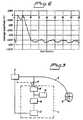
- Figure 1shows a unipolar IEGM, measured between electrode tip and the casing of the heart stimulator, and the ECG, recorded during experiments on an animal.
- the recorded heart beatsare numbered from 0 to 25.
- Beats number 0 and 1represent two completely stimulated captures.
- Beats No. 7, 8, 9, and 10are fusion beats.
- the following beats No. 11-25are only stimulated heart beats.
- FIG 2the average amplitude values of the recorded IEGM are shown for each of the heart beats (and also for subsequent heart beats up to heart beat No. 40). These average amplitude values are determined by the evoked response detector according to the invention as will be described below.
- the average amplitudesare situated between the measured average amplitude for pseudofusion beats and the amplitude for the completely stimulated beats.
- the absolute values of the average amplitudes of these fusion beatsare continuously increasing from beat 7 to beat 10 due to the fact that the beats become more and more stimulated.
- Fig. 3shows a block diagram of the principal layout of the heart stimulator according to the invention.
- the stimulatorcomprises a pulse generator 2 which through a lead 6 is connected to the heart 8 of a patient.
- the pulse generator 2is devised to produce stimulation pulses of varying amplitudes which through the lead 6 are transferred to the heart 8.
- the evoked response detector 4 of the heart stimulatoris also connected to the lead 6.
- the evoked response detector 4comprises filter and measuring means 10.
- the filtered electrode signalis supplied to an averaging means 16 and to comparison means 12 for distinguishing capture also for fusion beats and losses of capture by comparing the average amplitudes obtained from the averaging means 16 with suitably selected limit values as described above in connection with figure 2.
- the filter and measurement means 10is disconnected by the switch 11 from the lead 6 during stimulation.
- Timing means 14are provided for determining an evoked response time window during which the electrode signal is measured and stored. This evoked response window normally extends from 15 to 55 msec after stimulation.
- the measured electrode signal(IEGM) is sampled and digitized during this evoked response window, and the mean value of these samples is formed.
- This procedureis performed in the averaging means 16, which thus supplies to the comparison means 12 an average amplitude value for each heart beat.
- a suitable sampling frequencycan be e.g. 512 Hz, which results in about 20 samples per beat.
- IEGMmeasured electrode signal
- Fig. 4shows in more detail one embodiment of the evoked response detector according to the invention.
- the heart electrode signal picked up by the lead 6 in fig. 3is then supplied to a highpass filter 20.
- An amplifier 22 and an A/D converter 24are provided for amplifying and A/D converting respectively the filtered signal.
- the block 26comprises a digital signal processor for calculating the average amplitudes of the measured electrode signals and comparing them with suitably selected limit values as described above.
- the algorithm for distinguishing between capture also for fusion beats, and loss of captureis implemented in software by use of a microprocessor.
- this algorithmcan also be implemented in random logic, which means realization by ordinary logic element, that is logic gates.
- the detector according to the inventioncan also be implemented in the heart stimulator electronics by use of switch capacitor (SC) technique.
- SCswitch capacitor
- the algorithmis then implemented in SC technique, where different capacitors serve as memory elements for storing the different electrode potentials and SC-adding, subtracting and multiplying circuits are used for performing the necessary calculations as explained above.
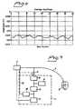
- Figure 5shows a unipolar IEGM and a curve showing the respiration flow recorded during experiments on an animal.
- IEGM curvean amplitude variation can be seen corresponding to the respiration flow.
- Figure 6shows the average amplitudes obtained from the IEGM in figure 5 and analyzed by the detector according to the invention.
- the amplitude variation in dependence of the respirationcan clearly be seen.
- a respiration cyclecomprises approximately 6-9 average values.
- FIG. 7is a block diagram of the principal layout of the heart stimulator according to a second advantageous embodiment of the invention.
- This embodimentcomprises, in addition to the embodiment described in relation to Figure 3, a respiration signal determining means 28 supplied with the average values generated by the averaging means 16.
- the respiration signal determining means 28generates a respiration signal 30, representing the respiration rate of the patient, from a predetermined number of said average values .
- the respiration signal 30is applied to the pulse generator 2 where it is used as a control signal for controlling the stimulation rate in accordance with a respiration rate responsive algorithm.
- Using the respiration rate to control the stimulation rate of a pacemakeris well known the to a person skilled in the art of pacemakers, cf. e.g. US-4,702,253 and is therefore not described herein.
Landscapes
- Health & Medical Sciences (AREA)
- Cardiology (AREA)
- Heart & Thoracic Surgery (AREA)
- Engineering & Computer Science (AREA)
- Biomedical Technology (AREA)
- Nuclear Medicine, Radiotherapy & Molecular Imaging (AREA)
- Radiology & Medical Imaging (AREA)
- Life Sciences & Earth Sciences (AREA)
- Animal Behavior & Ethology (AREA)
- General Health & Medical Sciences (AREA)
- Public Health (AREA)
- Veterinary Medicine (AREA)
- Electrotherapy Devices (AREA)
Description
This embodiment comprises, in addition to the embodimentdescribed in relation to Figure 3, a respiration signaldetermining means 28 supplied with the average valuesgenerated by the averaging means 16. The respiration signaldetermining means 28 generates a
Claims (8)
- A heart stimulator comprising an evoked responsedetector (4), said heart stimulator comprising a pulsegenerator (2) for producing stimulation pulses for deliveryto the heart (8) of a patient through a lead (6) intended tobe connected to the pulse generator and introduced into theheart, said evoked response detector comprising measuringmeans (10) for measuring electrode signals picked up by thelead,characterized in that said evoked response detector comprises an averaging means (16)adapted to form an average value of the amplitude of thepicked up electrode signal for each heart beat andin that said evoked response detector comprises acomparison means (12) adapted to determine whether apicked up electrode signal results from a fusion beat or notby comparing said average value with predetermined limitvalues,
said comparison means is being arranged to compare saidaverage values with two different predetermined limit values,corresponding evoked response signals being considered toresult from fusion beats, if said average values are withinthe interval between said two limit values. - The heart stimulator according to claim 1,characterized in that said measuring means (10) isadapted to sample and digitize said picked up electrodesignal in a predetermined evoked response time window,starting a predetermined time after the delivery of astimulation pulse.
- The heart stimulatoraccording to claim 2,characterized in that said measuring means is adaptedto determine the DC level of the measured electrode signalsand subtract this DC level from each sample, whereupon saidaveraging means is adapted to form the average value of saidsamples from said evoked response time window to form saidaverage value of the amplitude of the measured electrode signal.
- The heart stimulator according to claims 2 or 3,characterized in that sampling frequency and lengthof said evoked response window are chosen such that a numberof samples of the order of 20 is obtained for each sampledevoked response signal.
- The heart stimulator according to any of the precedingclaims,characterized in that said lead is unipolar.
- The heart stimulator according to any of the precedingclaims,characterized in that a respiration signaldetermining means (28) is provided whereby a respirationsignal (30), representing the respiration rate of thepatient, is determined from a predetermined number of saidaverage values by said respiration signal determining means.
- The heart stimulator according to claim 6,characterized in that said respiration signal isdetermined from a variation of the amplitudes of saidpredetermined number of said average values.
- The heart stimulator according to claim7,characterized in that said determined respirationrate is used to control the stimulation rate of said pulsegenerator.
Applications Claiming Priority (3)
| Application Number | Priority Date | Filing Date | Title |
|---|---|---|---|
| SE9802153 | 1998-06-16 | ||
| SE9802153ASE9802153D0 (en) | 1998-06-16 | 1998-06-16 | Heart stimulator |
| PCT/SE1999/001019WO1999065569A1 (en) | 1998-06-16 | 1999-06-09 | Evoke response detector, averaging the value of the amplitude of the picked up electrode signal |
Publications (2)
| Publication Number | Publication Date |
|---|---|
| EP1087819A1 EP1087819A1 (en) | 2001-04-04 |
| EP1087819B1true EP1087819B1 (en) | 2004-05-26 |
Family
ID=20411734
Family Applications (1)
| Application Number | Title | Priority Date | Filing Date |
|---|---|---|---|
| EP99931681AExpired - LifetimeEP1087819B1 (en) | 1998-06-16 | 1999-06-09 | Evoke response detector, averaging the value of the amplitude of the picked up electrode signal |
Country Status (4)
| Country | Link |
|---|---|
| EP (1) | EP1087819B1 (en) |
| DE (1) | DE69917635T2 (en) |
| SE (1) | SE9802153D0 (en) |
| WO (1) | WO1999065569A1 (en) |
Families Citing this family (4)
| Publication number | Priority date | Publication date | Assignee | Title |
|---|---|---|---|---|
| US6192275B1 (en)* | 1999-05-11 | 2001-02-20 | Cardiac Pacemakers, Inc. | Adaptive evoked response sensing for automatic capture verification |
| DE19938376A1 (en)* | 1999-08-06 | 2001-02-08 | Biotronik Mess & Therapieg | Device for the detection of fusion events when electrostimulation of the heart |
| SE0003480D0 (en)* | 2000-09-27 | 2000-09-27 | St Jude Medical | Implantable heart stimulator |
| AU2003256197A1 (en)* | 2003-08-28 | 2005-03-16 | St. Jude Medical Ab | Medical implant for evoked response detection having an adaptive detection time window |
Family Cites Families (3)
| Publication number | Priority date | Publication date | Assignee | Title |
|---|---|---|---|---|
| US5350410A (en)* | 1992-11-23 | 1994-09-27 | Siemens Pacesetter, Inc. | Autocapture system for implantable pulse generator |
| US5458623A (en)* | 1994-03-04 | 1995-10-17 | Telectronics Pacing Systems, Inc. | Automatic atrial pacing threshold determination utilizing an external programmer and a surface electrogram |
| US5391192A (en)* | 1994-03-04 | 1995-02-21 | Telectronics Pacing Systems, Inc. | Automatic ventricular pacing pulse threshold determination utilizing an external programmer and a surface electrocardiogram |
- 1998
- 1998-06-16SESE9802153Apatent/SE9802153D0/enunknown
- 1999
- 1999-06-09WOPCT/SE1999/001019patent/WO1999065569A1/enactiveIP Right Grant
- 1999-06-09EPEP99931681Apatent/EP1087819B1/ennot_activeExpired - Lifetime
- 1999-06-09DEDE69917635Tpatent/DE69917635T2/ennot_activeExpired - Lifetime
Also Published As
| Publication number | Publication date |
|---|---|
| EP1087819A1 (en) | 2001-04-04 |
| WO1999065569A1 (en) | 1999-12-23 |
| SE9802153D0 (en) | 1998-06-16 |
| DE69917635D1 (en) | 2004-07-01 |
| DE69917635T2 (en) | 2005-06-02 |
Similar Documents
| Publication | Publication Date | Title |
|---|---|---|
| US5417718A (en) | System for maintaining capture in an implantable pulse generator | |
| EP0561781B1 (en) | Electronic capture detection for a pacer | |
| US6192275B1 (en) | Adaptive evoked response sensing for automatic capture verification | |
| US5873898A (en) | Microprocessor capture detection circuit and method | |
| US6163724A (en) | Microprocessor capture detection circuit and method | |
| US5718720A (en) | Implantable cardiac stimulator with capture detection and impedance based autotuning of capture detection | |
| US5683426A (en) | Apparatus and method for detecting the progression of AV nodal block and atrial capture | |
| EP0826392B1 (en) | Apparatus for extracting an evoked response component from a sensed cardiac signal by suppressing electrode polarization components | |
| EP1023919A2 (en) | An implantable cardiac stimulation device | |
| US5954756A (en) | Microprocessor capture detection circuit and method | |
| WO2001043820A1 (en) | Cardiac management device with capability of noise detection in automatic capture verification | |
| WO1995007114A2 (en) | Apparatus and method for capture detection in a cardiac stimulator | |
| US6501989B1 (en) | Heart stimulator having an evoked response detector | |
| US7054688B1 (en) | Heart stimulator with evoked response detector and an arrangement for determining the stimulation threshold | |
| EP0237767A2 (en) | Rate responsive pacing using the ventricular gradient | |
| US6850800B1 (en) | Evoked response detector, averaging the value of the amplitude of the picked-up electrode signal | |
| EP1087819B1 (en) | Evoke response detector, averaging the value of the amplitude of the picked up electrode signal | |
| EP1091785B1 (en) | Evoked response detector for a heart stimulator | |
| US6954671B1 (en) | Implantable heart stimulator or which identifies the origin of heart signals | |
| US7286874B1 (en) | Ensemble averaging for evoked responses |
Legal Events
| Date | Code | Title | Description |
|---|---|---|---|
| PUAI | Public reference made under article 153(3) epc to a published international application that has entered the european phase | Free format text:ORIGINAL CODE: 0009012 | |
| 17P | Request for examination filed | Effective date:20010116 | |
| AK | Designated contracting states | Kind code of ref document:A1 Designated state(s):CH DE FR IT LI | |
| GRAP | Despatch of communication of intention to grant a patent | Free format text:ORIGINAL CODE: EPIDOSNIGR1 | |
| GRAS | Grant fee paid | Free format text:ORIGINAL CODE: EPIDOSNIGR3 | |
| GRAA | (expected) grant | Free format text:ORIGINAL CODE: 0009210 | |
| AK | Designated contracting states | Kind code of ref document:B1 Designated state(s):CH DE FR IT LI | |
| REG | Reference to a national code | Ref country code:CH Ref legal event code:EP | |
| REF | Corresponds to: | Ref document number:69917635 Country of ref document:DE Date of ref document:20040701 Kind code of ref document:P | |
| REG | Reference to a national code | Ref country code:CH Ref legal event code:NV Representative=s name:E. BLUM & CO. PATENTANWAELTE | |
| ET | Fr: translation filed | ||
| PLBE | No opposition filed within time limit | Free format text:ORIGINAL CODE: 0009261 | |
| STAA | Information on the status of an ep patent application or granted ep patent | Free format text:STATUS: NO OPPOSITION FILED WITHIN TIME LIMIT | |
| 26N | No opposition filed | Effective date:20050301 | |
| REG | Reference to a national code | Ref country code:CH Ref legal event code:PFA Owner name:ST. JUDE MEDICAL AB Free format text:ST. JUDE MEDICAL AB# #175 84 JAERFAELLA (SE) -TRANSFER TO- ST. JUDE MEDICAL AB# #175 84 JAERFAELLA (SE) | |
| PGFP | Annual fee paid to national office [announced via postgrant information from national office to epo] | Ref country code:IT Payment date:20100626 Year of fee payment:12 | |
| PGFP | Annual fee paid to national office [announced via postgrant information from national office to epo] | Ref country code:CH Payment date:20100625 Year of fee payment:12 | |
| REG | Reference to a national code | Ref country code:CH Ref legal event code:PL | |
| PG25 | Lapsed in a contracting state [announced via postgrant information from national office to epo] | Ref country code:IT Free format text:LAPSE BECAUSE OF NON-PAYMENT OF DUE FEES Effective date:20110609 | |
| PG25 | Lapsed in a contracting state [announced via postgrant information from national office to epo] | Ref country code:CH Free format text:LAPSE BECAUSE OF NON-PAYMENT OF DUE FEES Effective date:20110630 Ref country code:LI Free format text:LAPSE BECAUSE OF NON-PAYMENT OF DUE FEES Effective date:20110630 | |
| PGFP | Annual fee paid to national office [announced via postgrant information from national office to epo] | Ref country code:FR Payment date:20120705 Year of fee payment:14 | |
| PGFP | Annual fee paid to national office [announced via postgrant information from national office to epo] | Ref country code:DE Payment date:20130627 Year of fee payment:15 | |
| REG | Reference to a national code | Ref country code:FR Ref legal event code:ST Effective date:20140228 | |
| PG25 | Lapsed in a contracting state [announced via postgrant information from national office to epo] | Ref country code:FR Free format text:LAPSE BECAUSE OF NON-PAYMENT OF DUE FEES Effective date:20130701 | |
| REG | Reference to a national code | Ref country code:DE Ref legal event code:R119 Ref document number:69917635 Country of ref document:DE | |
| REG | Reference to a national code | Ref country code:DE Ref legal event code:R119 Ref document number:69917635 Country of ref document:DE Effective date:20150101 | |
| PG25 | Lapsed in a contracting state [announced via postgrant information from national office to epo] | Ref country code:DE Free format text:LAPSE BECAUSE OF NON-PAYMENT OF DUE FEES Effective date:20150101 |