EP1087708B1 - Method for generating a pulse train of sterile liquid jet for medical uses - Google Patents
Method for generating a pulse train of sterile liquid jet for medical usesDownload PDFInfo
- Publication number
- EP1087708B1 EP1087708B1EP99925126AEP99925126AEP1087708B1EP 1087708 B1EP1087708 B1EP 1087708B1EP 99925126 AEP99925126 AEP 99925126AEP 99925126 AEP99925126 AEP 99925126AEP 1087708 B1EP1087708 B1EP 1087708B1
- Authority
- EP
- European Patent Office
- Prior art keywords
- previous
- suction
- communication
- liquid
- pressure
- Prior art date
- Legal status (The legal status is an assumption and is not a legal conclusion. Google has not performed a legal analysis and makes no representation as to the accuracy of the status listed.)
- Expired - Lifetime
Links
- 239000007788liquidSubstances0.000titleclaimsabstractdescription78
- 238000000034methodMethods0.000titleclaimsabstractdescription55
- 238000004891communicationMethods0.000claimsabstractdescription25
- 230000000737periodic effectEffects0.000claimsabstractdescription18
- 230000000694effectsEffects0.000claimsdescription6
- 238000002224dissectionMethods0.000claimsdescription4
- 238000007599dischargingMethods0.000claimsdescription3
- 238000002955isolationMethods0.000claims1
- 230000008569processEffects0.000abstractdescription21
- 238000010304firingMethods0.000abstractdescription11
- 238000005273aerationMethods0.000abstract1
- 238000013022ventingMethods0.000description15
- 239000004744fabricSubstances0.000description8
- 230000006870functionEffects0.000description6
- 230000008901benefitEffects0.000description4
- 239000000463materialSubstances0.000description4
- 230000001960triggered effectEffects0.000description4
- 230000006837decompressionEffects0.000description3
- 230000003749cleanlinessEffects0.000description2
- 230000000052comparative effectEffects0.000description2
- 230000007423decreaseEffects0.000description2
- 230000002950deficientEffects0.000description2
- 239000012530fluidSubstances0.000description2
- 239000012528membraneSubstances0.000description2
- 210000000056organAnatomy0.000description2
- 230000003252repetitive effectEffects0.000description2
- 230000000630rising effectEffects0.000description2
- 238000012163sequencing techniqueMethods0.000description2
- 240000008042Zea maysSpecies0.000description1
- 230000003416augmentationEffects0.000description1
- 230000015572biosynthetic processEffects0.000description1
- 238000004140cleaningMethods0.000description1
- 210000004087corneaAnatomy0.000description1
- 230000032798delaminationEffects0.000description1
- 230000001419dependent effectEffects0.000description1
- 238000009795derivationMethods0.000description1
- 230000037213dietEffects0.000description1
- 235000005911dietNutrition0.000description1
- 238000004945emulsificationMethods0.000description1
- 230000008571general functionEffects0.000description1
- 230000006872improvementEffects0.000description1
- 230000003472neutralizing effectEffects0.000description1
- 230000035515penetrationEffects0.000description1
- 230000000750progressive effectEffects0.000description1
- 230000010349pulsationEffects0.000description1
- 238000011084recoveryMethods0.000description1
- 230000002787reinforcementEffects0.000description1
- 230000029058respiratory gaseous exchangeEffects0.000description1
- 230000035939shockEffects0.000description1
- 239000007787solidSubstances0.000description1
- 239000007921spraySubstances0.000description1
- 238000001356surgical procedureMethods0.000description1
- 230000001360synchronised effectEffects0.000description1
Images


Classifications
- A—HUMAN NECESSITIES
- A61—MEDICAL OR VETERINARY SCIENCE; HYGIENE
- A61B—DIAGNOSIS; SURGERY; IDENTIFICATION
- A61B17/00—Surgical instruments, devices or methods
- A61B17/32—Surgical cutting instruments
- A61B17/3203—Fluid jet cutting instruments
- A—HUMAN NECESSITIES
- A61—MEDICAL OR VETERINARY SCIENCE; HYGIENE
- A61M—DEVICES FOR INTRODUCING MEDIA INTO, OR ONTO, THE BODY; DEVICES FOR TRANSDUCING BODY MEDIA OR FOR TAKING MEDIA FROM THE BODY; DEVICES FOR PRODUCING OR ENDING SLEEP OR STUPOR
- A61M1/00—Suction or pumping devices for medical purposes; Devices for carrying-off, for treatment of, or for carrying-over, body-liquids; Drainage systems
- A61M1/71—Suction drainage systems
- A61M1/77—Suction-irrigation systems
- A—HUMAN NECESSITIES
- A61—MEDICAL OR VETERINARY SCIENCE; HYGIENE
- A61M—DEVICES FOR INTRODUCING MEDIA INTO, OR ONTO, THE BODY; DEVICES FOR TRANSDUCING BODY MEDIA OR FOR TAKING MEDIA FROM THE BODY; DEVICES FOR PRODUCING OR ENDING SLEEP OR STUPOR
- A61M1/00—Suction or pumping devices for medical purposes; Devices for carrying-off, for treatment of, or for carrying-over, body-liquids; Drainage systems
- A61M1/71—Suction drainage systems
- A61M1/74—Suction control
- A61M1/75—Intermittent or pulsating suction
Definitions
- the inventionrelates to a method of generating a pulse train of a liquid jet sterile pulsed-aspirated and pulsed-suctioned liquid jet thus generated for feeding a handpiece or a catheter for particular applications surgical and medical.
- EPmay be mentioned n ° 0636345 in the name of SENTINEL MEDICAL concerning a pulsed jet surgical instrument of liquid to cutting and emulsification purposes with a joint suction for the evacuation of the liquid and biological residues.
- the pulsed jetcomes from the movement of back and forth repeated an amplifier piston that receives the liquid under low pressure.
- suctionis also continuous and separate. However, he does not This is not cutting but delamination and disintegration for the evacuation of materials and troublesome tissues.
- pulsed liquid jetspreviously known high-pressure liquid pulse trains triggered to order and projected on the dissection area.
- the liquid sprayis then evacuated by suction continuously or when it exceeds a certain quantity considered inconvenient for the continuation of the dissection work.
- the dissection yieldis only slightly better than that of a jet continuous because of rebound phenomena.
- DE-A-37 15 418shows a process as defined in the introductory part of claim 1.
- the present inventionaims to remedy the aforementioned drawbacks by proposing a method of generating a pulse train of a liquid jet sterile pulsed-aspirated for feeding a handpiece, a catheter or the like, for use surgical or medical.
- the process according to the inventionis defined by claim 1.
- the dependent claimsrelate to variants of the process according to the invention. This process allows to create a jet ejected and sucked from a high operative efficiency.
- the inventionrelates to a circuit according to claim 25 for the implementation process according to the invention.
- This circuitis characterized in that one puts in works a liquid way under pressure for example under high pressure and a pneumatic way suction and in that we order periodically firing the jet under pressure during the periodic application of aspiration and in this that the fabric is released during the cut of suction by venting.
- the method according to the inventionhas many advantages.
- the fabricBeing a pulsed-aspirated jet, that is to say a shot fired at the same time as works the suction, the fabric remains plated, that is to say stretched momentarily before and during the shot at the end of the end sleeve of the piece to hand, then relaxes during the final phase of aspiration. This is a shot on a fabric stretched which ensures precision and cleanliness of the cut and the operative field.
- the variant of the basic processaims to remedy these disadvantages.
- the inventive principle of this variantis to get a falling edge of the slots pressure of the jet of liquid not only by the pressure cut and therefore that of the jet, but by a simultaneous or almost simultaneous communication simultaneous liquid supply line with outside especially in the air or with the suction or the vacuum generator.
- the variant of the basic processprovides, bypass on the feed tube in pressurized liquid, a connected duct branch to the vacuum generator or to the air through a frequency-controlled cut-opening device recurrence in synchronism with others controls, so as to achieve, before shooting following, the discharge of the residual pressure existing in the liquid supply duct under pressure.
- This periodic order for implementation communication of the pressure conduit with the outsideoccurs simultaneously or immediately before or after the cut command of the conduit high pressure supply.
- the basic process according to the inventionconsists, using all appropriate means, mechanical, electrical, electromechanical, electromagnetic or other, to generate on command from a first conduit carrying a liquid sterile under pressure delivered by a generator and of a second pneumatic suction duct, a impulse train of a sterile pulsed-aspirated liquid jet and project it through a handpiece for surgical applications or medical.
- a closing-openingmeans sequential flow rate according to the same frequency but with an opening time that can be different for the two fluids.
- the firing of the liquid jet under pressureis carried out during suction time intervals that is to say during the opening time of the closing-opening means of the suction duct.
- the processis completed in that one neutralizes vacuum aspiration air just after closing the duct suction, for example by venting the suction line to stop aspiration.
- the basic processcan be implemented by simple means, such as means electromechanical actuators or others acting in pinching or crushing on a flexible duct conveying the liquid or the air sucked or by hydraulic break components such as flow shutters or solenoid valves, all controlled by an electronic circuit of sequencing.
- ventingis carried out by the suction duct for example by a derivation of it periodically open and closed, but any other way to compensate for the strength Sucking to relax the fabric is possible.
- the shotwith some delay in relation to the beginning of aspiration.
- the shotis from preferably in the first half of the width of aspiration impulse and stops preferably before the start of the second half. Breathing takes place after cutting off the suction and preference but not necessarily right after this cut.
- the breatheris short-lived and follows quickly the end of aspiration.
- the rising edges of the impulsesare vertical representations.
- the slopewill depend on the type of closing-opening device flow rate used and in particular its inertia.
- the frequency of recurrence of the diet impulse and pulse widthare modifiable. We can thus perform changes must according to the application surgical, namely the type of intervention, target organ or tissue and depth of intervention in the human body.
- the device generating this pulse trainwill allow to vary these main parameters including time parameters.
- the frequency of recurrence F Rmay for example be in a range between a fraction of Hertz and some Hertz, for example between 0.1 and 10 Hz.
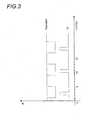
- Figure 2shows waveforms based on the same principle of a liquid jet under pressure pulsed-aspirated, object of the basic process according to the invention.
- the duration of the shot and the suction durationincrease simultaneously.
- the control pulses or the openings corresponding to the ventingmove on the time axis to start just after cutting the suction.
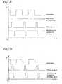
- Figure 3shows waveforms without venting.
- This sample applicationis the one of an open end sleeve handpiece on its periphery for which the loosening of the fabric after the shooting is done automatically after the cut off the suction.
- Figure 4is intended to illustrate the problem solved by the variant of the basic process.
- This rampdelimits, with the ideal vertical rear edge, a zone of inefficiency represented hatched, the extent of which increases with the frequency of recurrence F R.
- the impulseenlarges in width by a rear extension and the pressure cut is no longer frank but becomes progressive.
- the present improvementaims to remedy this drawback by correcting the deformation of the trailing edge of the pulse of pressure by a controlled decompression or automatic liquid supply tube pressure of the handpiece. This decompression is synchronized with the pressure pulses.
- This variant of the basic processproceeds from the general inventive idea which consists in generating a pulse train of a pulsed liquid jet with suction in which the feed pipe of the liquid pressure generator is put in periodic communication with a vacuum generator or with the air to give rise to a pulsation regime of liquid ejection by a handpiece with a recurrence frequency F R , in which the rear edge of the liquid pressure pulse is obtained by cutting off the supply of pressurized liquid and discharging residual pressure remaining or remaining in the supply line of the handpiece in pressurized liquid by placing the conduit in communication with the outside.
- a particularly sterile fluid generator under pressure GHPis connected to a handpiece 1 or PAM, for example surgical, by a tubular supply pressure 2 through a cut-opening member 3 controlled from periodically at a recurrence frequency F R.
- the liquid under pressureis, for example, generated and ejected at a pressure between 15 and 100 bar depending on the intended application.
- a suction circuitcomprises a GDP depression generator connected to the handpiece 1 by an independent suction duct 4 through an isolation-communication element 5 controlled at the recurrence frequency F R in synchronism with the control in cut-opening of the tubular supply pipe 2 in liquid under pressure by the cutoff-opening member 3.
- a venting device(not shown) is grafted onto the suction duct. It is controlled in synchronism with the other commands at the recurrence frequency F R. This venting device aims to neutralize the suction and thus relax the fabric just before a new shot.
- this branch derivative 6is that of periodically setting the supply duct 2 in liquid under pressure in communication with the outside. More particularly this function is that of decompressing, that is to say quickly evacuate the residual pressure, immediately before or after or at the close of supply duct 2 in liquid under pressure.
- one of the decompression means possibleis the connection to a GDP depression generator, which may be the same as that of the suction circuit, and this at through a switch device 7 ensuring the ordered opening and closing of the communication with this generator GDP and this in synchronism with the control of the jet under pressure.
- valve ordered or a permeable membrane or any other similar meanswe quote a valve ordered or a permeable membrane or any other similar means.
- the residual pressurecan also until some frequency be evacuated so simple and automatic by an adjacent exit connected to a MALA device with a pressure threshold or having a constant periodic delay to the opening.
- outsidein its most general sense, that is to say a space or volume outside the duct 2.
- itmay also be a buffer volume, an extensible closed volume, a flexible membrane ...
- shootingtakes place during the suction, that is to say that the pulse of pressure is triggered and cut in the meantime of time corresponding to a niche of depression.
- FIG. 10shows the command air venting is carried out just after cutting off the suction to favor detachment and relaxation of tissues.
- the second part of Figure 10illustrates control of the end of the shot by aspiration.
- the pressure pulse of the shot at the end of the handpiece without correctionis the one represented on the third curve leaving appear the zone of inefficiency represented hatched.
- the cutis controlled of the firing pulse by the depression before it normal cut by the opening-closing member 3.
- the pressure pulse starting at the time t1is cut in advance at time t2 by an opening fast command of communication with the outside and especially with suction.
- We calibrate the firing pulse at a duration Tby performing a sharp and straight cut as it appears on the last waveform shown in this figure 10.
- the duration of the depression impulse or suction of the fire pressure duct which triggers the cut (4th curve)is sufficient to realize the total discharge of the pressure residual. It remains weak, however.
- the depression or aspiration impulsehas purpose of creating a liquid call and therefore a discharge before or just before the break of the liquid pressure, thus neutralizing the afterglow pressure and guaranteeing an abrupt fall of the pressure.
- the present inventionis implemented by a source of liquid under pressure and by a sequencing apparatus that is to say stop and sudden start of the liquid jet under pressure feeding a handpiece or catheter.
- impulsescan come repetitive mechanical actions for example on a flexible conduit.
- the pulse train triggered by the operatorcontinues at the recurrence frequency F R until the manual stop command ordered by the operator.
Landscapes
- Health & Medical Sciences (AREA)
- Life Sciences & Earth Sciences (AREA)
- Heart & Thoracic Surgery (AREA)
- General Health & Medical Sciences (AREA)
- Public Health (AREA)
- Biomedical Technology (AREA)
- Surgery (AREA)
- Veterinary Medicine (AREA)
- Engineering & Computer Science (AREA)
- Animal Behavior & Ethology (AREA)
- Molecular Biology (AREA)
- Nuclear Medicine, Radiotherapy & Molecular Imaging (AREA)
- Medical Informatics (AREA)
- Pulmonology (AREA)
- Vascular Medicine (AREA)
- Anesthesiology (AREA)
- Hematology (AREA)
- Surgical Instruments (AREA)
- External Artificial Organs (AREA)
- Medicines That Contain Protein Lipid Enzymes And Other Medicines (AREA)
- Eyeglasses (AREA)
Abstract
Description
Translated fromFrenchL'invention se rapporte à un procédé degénération d'un train impulsionnel d'un jet liquidestérile pulsé-aspiré et au jet liquide pulsé-aspiréainsi généré pour l'alimentation d'une pièce à mainou d'un cathéter en vue d'applications notammentchirurgicales et médicales.The invention relates to a method ofgenerating a pulse train of a liquid jetsterile pulsed-aspirated and pulsed-suctioned liquid jetthus generated for feeding a handpieceor a catheter for particular applicationssurgical and medical.
On connaít déjà l'utilisation des jetspulsés d'un liquide stérile sous haute pression à desfins d'interventions chirurgicales.We already know the use of jetspulses of a sterile liquid under high pressure tosurgical purposes.
On peut citer par exemple à cet effet EPn° 0636345 au nom de SENTINEL MEDICAL qui concerne uninstrument chirurgical à jet pulsé de liquide à desfins de découpe et d'émulsification avec uneaspiration conjointe pour l'évacuation du liquide etdes résidus biologiques.For example, EP may be mentionedn ° 0636345 in the name of SENTINEL MEDICAL concerning apulsed jet surgical instrument of liquid tocutting and emulsification purposes with ajoint suction for the evacuation of the liquid andbiological residues.
Le jet pulsé provient du mouvement de va-et-vientrépété d'un piston amplificateur qui reçoit leliquide sous faible pression.The pulsed jet comes from the movement of back and forthrepeated an amplifier piston that receives theliquid under low pressure.
L'inconvénient majeur de ce système concernel'utilisation d'un piston qui ne peut produire qu'unseul train d'impulsions pendant son trajet de travaille long de sa course. Il convient ensuite de remplirà nouveau la chambre du piston, ce qui condamne cedispositif à un fonctionnement discontinu peucompatible avec les exigences de travail deschirurgiens.The major disadvantage of this system concernsthe use of a piston that can only produce onesingle pulse train during his work tripalong its course. It is then necessary to fillagain the piston chamber, which condemns thisdevice to a little discontinuous operationcompatible with the work requirements ofsurgeons.
Il existe également des inventions serapportant à la chirurgie de l'oeil dans lesquellesun jet pulsé de liquide est dirigé sur l'oeil etnotamment sur la cornée en vue d'un travail dedésintégration des tissus défectueux et dedécollement des matières et corps déposés ou incrustés. Ces inventions sont protégées par lesbrevets américains n° 3,818,913 et 3,930,505 au nomde WALLACH.There are also inventionsrelating to eye surgery in whicha pulsating jet of liquid is directed to the eye andespecially on the cornea for a work ofdisintegration of defective tissues anddetachment of deposited materials or bodiesinlaid. These inventions are protected byU.S. Patent Nos. 3,818,913 and 3,930,505 in the name offrom WALLACH.
Il s'agit de jets pulsés à haute fréquencedestinés par la haute cadence de répétition à untravail de désintégration par trains de frappes pourle nettoyage du cristallin en le débarrassant destissus défectueux et des matières et corps étrangers.Il est prévu classiquement une aspiration séparéepour l'évacuation du liquide et des résidus dutravail de désintégration.These are high frequency pulsed jetsdestined by the high rate of repetition to adisintegration work by trains of strikes forcleaning the lens by ridding him ofdefective fabrics and foreign materials and bodies.It is expected classically a separate aspirationfor the evacuation of liquid and residues fromdisintegration work.
Dans ces derniers dispositifs, l'aspirationest également continue et séparée. Par contre, il nes'agit pas de découpe mais de décollement et dedésintégration en vue de l'évacuation des matières etdes tissus gênants.In these latter devices, suctionis also continuous and separate. However, he does notThis is not cutting but delamination anddisintegration for the evacuation of materials andtroublesome tissues.
De façon générale, les jets liquides pulsésà haute pression connus antérieurement sont destrains d'impulsions liquides déclenchés sur commandeet projetés sur la zone de dissection.In general, pulsed liquid jetspreviously known high-pressureliquid pulse trains triggered to orderand projected on the dissection area.
Le liquide projeté est ensuite évacué paraspiration en continu ou lorsqu'il dépasse unecertaine quantité jugée gênante pour la poursuite dutravail de dissection.The liquid spray is then evacuated bysuction continuously or when it exceeds acertain quantity considered inconvenient for the continuation of thedissection work.
Dans ces réalisations, le chirurgien ne peutapprocher de trop près le tissu à disséquer parl'extrémité de la pièce à main en raison desprojections latérales de liquide et des éclaboussuresainsi générées troublant la visibilité du champopératoire.In these achievements, the surgeon can notget too close to the tissue to be dissected bythe end of the handpiece because ofLateral projections of liquid and splashingthus generated disturbing the visibility of the fieldprocedure.
Par ailleurs, le rendement de dissectionn'est que faiblement meilleur à celui d'un jetcontinu en raison des phénomènes de rebond.Moreover, the dissection yieldis only slightly better than that of a jetcontinuous because of rebound phenomena.
Finalement, la pénétration de liquide mêmestérile dans l'ouverture découpée et ceci enquantités faibles mais non négligeables, est uninconvénient pour le corps du patient qui doit l'éliminer en plus de toutes les autres surchargesliées à l'intervention.Finally, even liquid penetrationsterile in the cut opening and this insmall but significant quantities, is adisadvantage for the body of the patient who has toeliminate it in addition to all other surchargesrelated to the intervention.
DE-A-37 15 418 montre un procédé tel que défini dans la partie introductive de la revendication 1.DE-A-37 15 418 shows a process as defined in the introductory part of
La présente invention a pour but de remédieraux inconvénients précités en proposant un procédé degénération d'un train impulsionnel d'un jet liquidestérile pulsé-aspirépour l'alimentation d'une pièce à main, d'uncathéter ou analogue, en vue d'applicationschirurgicales ou médicales. Le procédé selon l'invention estdéfini par la revendication 1. Les revendications dépendantes concernentdes variantes du procédé selon l'invention.Ceprocédé permet de créer un jet éjecté et aspiré d'unegrande efficacité opératoire.The present invention aims to remedythe aforementioned drawbacks by proposing a method ofgenerating a pulse train of a liquid jetsterile pulsed-aspiratedfor feeding a handpiece, acatheter or the like, for usesurgical or medical. The process according to the invention isdefined by
En outre l'invention concerne un circuit selon la revendication 25pour la mise en oeuvre procédé selonl'invention. Ce circuit se caractérise en ce que l'on met enoeuvre une voie de liquide sous pression par exemplesous haute pression et une voie pneumatiqued'aspiration et en ce que l'on commandepériodiquement le tir du jet sous pression pendantl'application périodique de l'aspiration et en cequ'on libère le tissu pendant la coupure del'aspiration par une mise à l'air.In addition, the invention relates to a circuit according to claim 25for the implementation process according tothe invention. This circuit is characterized in that one puts inworks a liquid way under pressure for exampleunder high pressure and a pneumatic waysuction and in that we orderperiodically firing the jet under pressure duringthe periodic application of aspiration and in thisthat the fabric is released during the cut ofsuction by venting.
Le procédé selon l'invention présente denombreux avantages.The method according to the invention hasmany advantages.
Il permet d'éviter les projections latéraleset les éclaboussures de toute sorte et de ce faitprocure une bonne visibilité du champ opératoire enmême temps que la possibilité d'approcher de trèsprès le tissu à découper.It avoids lateral projectionsand splashing of any kind and thereforeprovides good visibility of the surgical field bysame time as the possibility of approaching verynear the fabric to be cut.
S'agissant d'un jet pulsé-aspiré, c'est-à-dired'un jet tiré en même temps que fonctionnel'aspiration, le tissu reste plaqué c'est-à-diretendu momentanément avant et pendant le tir àl'extrémité du manchon d'extrémité de la pièce àmain, puis se détend pendant la phase finale del'aspiration. On procède ainsi à un tir sur un tissutendu qui assure précision et propreté de la découpeet du champ opératoire.Being a pulsed-aspirated jet, that is to saya shot fired at the same time as worksthe suction, the fabric remains plated, that is to saystretched momentarily before and during the shot atthe end of the end sleeve of the piece tohand, then relaxes during the final phase ofaspiration. This is a shot on a fabricstretched which ensures precision and cleanliness of the cutand the operative field.
La durée d'application du jet étant courte,une faible consommation en liquide stérile estassurée.The duration of application of the jet being short,a low consumption of sterile liquid isassured.
Lors de phases particulières du travailchirurgical, ou pour des applications spécifiques, ilest souhaitable d'augmenter la fréquence derécurrence du jet de pression.During particular phases of worksurgical, or for specific applications, itis desirable to increase the frequency ofrecurrence of the pressure jet.
Or, lorsque la fréquence de récurrence dujet augmente, et/ou lorsque à partir d'une certainelongueur, l'inertie, l'élasticité et l'effetréservoir liés à la déformation du tubed'alimentation de la pièce à main et la pressionrésiduelle deviennent sensibles, ce procédé de basedevient moins performant.However, when the frequency of recurrencejet increases, and / or when from a certainlength, inertia, elasticity and effecttank related to tube deformationsupply of the handpiece and the pressureresidual become sensitive, this basic processbecomes less efficient.
En effet, malgré la présence d'une armaturede renforcement, le tube d'alimentation du liquide enhaute pression se déforme légèrement. Le front dedescente de l'impulsion de pression non seulements'incline, mais s'arrondit laissant apparaítre unezone d'inefficacité augmentant avec la fréquence desimpulsions qui empiète sur la zone de récupération etd'aspiration, si bien qu'à partir d'une limitesupérieure de fréquences on se rapproche du régimecontinu en perdant les avantages liés au régimepulsé.Indeed, despite the presence of a framereinforcement, the liquid feed tube intohigh pressure is deformed slightly. The frontdescent of the pressure pulse not onlybows, but rounds off letting appear azone of inefficiency increasing with the frequency ofimpulses that encroach on the area of recovery andsuction, so that from a limithigher frequency we get closer to the regimecontinuous by losing the benefits of the planpulsed.
Or, l'existence d'un front de coupure de lahaute pression franc, raide et de courte durée estune condition importante de précision, de commodité et d'efficacité dans le travail chirurgical.However, the existence of a cutting front of thehigh pressure, steep and short-lived isan important condition of accuracy, convenienceand efficiency in surgical work.
La variante du procédé de base a pour but deremédier à ces inconvénients.The variant of the basic process aims toremedy these disadvantages.
Le principe inventif de cette varianteconsiste à obtenir un front de descente des créneauxde pression du jet de liquide non plus seulement parla coupure de pression et donc celle du jet, mais parune mise en communication simultanée ou quasisimultanée du conduit d'alimentation en liquide avecl'extérieur notamment à l'air ou avec l'aspiration oule générateur de vide.The inventive principle of this variantis to get a falling edge of the slotspressure of the jet of liquid not only bythe pressure cut and therefore that of the jet, but bya simultaneous or almost simultaneous communicationsimultaneous liquid supply line withoutside especially in the air or with the suction orthe vacuum generator.
Selon la variante du procédé de base, onprévoit, en dérivation sur le tube d'alimentation enliquide sous pression, une branche de conduit reliéeau générateur de dépression ou à l'air à travers unorgane de coupure-ouverture commandé à la fréquencede récurrence en synchronisme avec les autrescommandes, de manière à réaliser, avant le tirsuivant, la décharge de la pression résiduelleexistant dans le conduit d'alimentation en liquidesous pression. Cette commande périodique de mise encommunication du conduit de pression avec l'extérieurs'effectue simultanément ou immédiatement avant ouaprès la commande de coupure du conduitd'alimentation en haute pression.According to the variant of the basic process,provides, bypass on the feed tube inpressurized liquid, a connected duct branchto the vacuum generator or to the air through afrequency-controlled cut-opening devicerecurrence in synchronism with otherscontrols, so as to achieve, before shootingfollowing, the discharge of the residual pressureexisting in the liquid supply ductunder pressure. This periodic order for implementationcommunication of the pressure conduit with the outsideoccurs simultaneously or immediately before orafter the cut command of the conduithigh pressure supply.
Cette variante du procédé présente diversavantages supplémentaires :
- front arrière de l'impulsion de pression marquantl'arrêt bien raide lorsque la fréquence derécurrence augmente ;
- efficacité et propreté dans le travail chirurgical ;
- perfectionnement très facile à mettre en oeuvre.
- the trailing edge of the pressure pulse marking the steep stopping when the recurrence frequency increases;
- efficiency and cleanliness in surgical work;
- perfecting very easy to implement.
D'autres caractéristiques et avantages del'invention apparaítront dans la description quisuit, donnée à titre d'exemple non limitatif enréférence aux dessins dans lesquels :
- la figure 1 est un graphique des formes d'ondes debase des paramètres du train impulsionnel enfonction du temps ;
- la figure 2 est un graphique des formes d'ondesselon une première variante à durée de tir plusimportante ;
- la figure 3 est un graphique des formes d'ondes detirs ne faisant pas intervenir de mise à l'air ;
- la figure 4 est une représentation graphiquecomparative de trois trains d'impulsions depression P de liquide en fonction du temps « t » àfréquences de récurrence FR croissantes montrant lazone d'inefficacité du procédé de base grandissantavec l'augmentation de la fréquence de récurrence ;
- la figure 5 est une vue du montage de base montrantles liaisons avec les différentes sources et lesemplacements des organes de coupure-ouverture enutilisant un générateur de dépression GDP ;
- les figures 6 et 7 sont des vues analogues maisavec une liaison à un dispositif de mise à l'aircommandé MALC ou automatique MALA ;
- la figure 8 est un graphique des formes d'ondes desdifférentes grandeurs en pression P formant le jetpulsé représentées en fonction du temps « t » avecmise périodique à l'air ;
- la figure 9 est un graphique des formes d'ondes desdifférentes grandeurs en pression P formant le jetpulsé représentées en fonction du temps « t » sansmise périodique à l'air ;
- la figure 10 est un graphique des formes d'ondesdes différentes grandeurs en pression P formant lejet pulsé représentées en fonction du temps « t »avec commande du front arrière de chute de pressionà partir de l'aspiration.
- Figure 1 is a graph of the basic waveforms of the parameters of the pulse train as a function of time;
- Figure 2 is a graph of waveforms according to a first variant with longer firing time;
- Fig. 3 is a graph of shot waveforms not involving venting;
- FIG. 4 is a comparative graphical representation of three streams of liquid pressure pulses P as a function of time "t" with increasing recurrence frequencies FR showing the zone of inefficiency of the basic process growing with the increase of the frequency of recurrence;
- FIG. 5 is a view of the basic assembly showing the connections with the different sources and the locations of the cutoff-opening members using a GDP negative generator;
- Figures 6 and 7 are similar views but with a connection to a MALC or MALA controlled venting device;
- FIG. 8 is a graph of the waveforms of the various pressure variables P forming the pulsed jet represented as a function of time "t" with periodic exposure to air;
- FIG. 9 is a graph of the waveforms of the various pressure variables P forming the pulsed jet represented as a function of time "t" without periodic exposure to air;
- FIG. 10 is a graph of the waveforms of the various pressure variables P forming the pulsed jet represented as a function of time "t" with control of the trailing edge of pressure drop from the suction.
Le procédé de base selon l'inventionconsiste, à l'aide de tous les moyens appropriés,mécaniques, électriques, électromécaniques, électromagnétiques ou autres, à générer sur commandeà partir d'un premier conduit transportant un liquidestérile sous pression délivré par un générateur etd'un deuxième conduit pneumatique d'aspiration, untrain impulsionnel d'un jet liquide stérile pulsé-aspiréet à le projeter par l'intermédiaire d'unepièce à main en vue d'applications chirurgicales oumédicales.The basic process according to the inventionconsists, using all appropriate means,mechanical, electrical, electromechanical,electromagnetic or other, to generate on commandfrom a first conduit carrying a liquidsterile under pressure delivered by a generator andof a second pneumatic suction duct, aimpulse train of a sterile pulsed-aspirated liquid jetand project it through ahandpiece for surgical applications ormedical.
Plus particulièrement, on utilise pourchacun des conduits, de liquide d'une part etd'aspiration d'autre part, un moyen de fermeture-ouvertureséquentiel du débit selon la même fréquencemais avec une durée d'ouverture pouvant êtredifférente pour les deux fluides.In particular, we use toeach of the conduits, of liquid on the one hand andon the other hand, a closing-opening meanssequential flow rate according to the same frequencybut with an opening time that can bedifferent for the two fluids.
Selon le procédé de base de l'invention, letir du jet liquide sous pression, c'est-à-direl'ouverture du moyen de fermeture-ouverture duconduit de liquide, s'effectue pendant lesintervalles de temps d'aspiration c'est-à-dirependant la durée d'ouverture du moyen de fermeture-ouverturedu conduit d'aspiration.According to the basic method of the invention, thefiring of the liquid jet under pressure, that is to saythe opening of the closing-opening means of theliquid line, is carried out duringsuction time intervals that is to sayduring the opening time of the closing-opening meansof the suction duct.
Le procédé est complété en ce que l'onréalise une neutralisation de l'aspiration par vided'air juste après la fermeture du conduitd'aspiration, par exemple en mettant à l'air leconduit d'aspiration pour stopper l'aspiration.The process is completed in that oneneutralizes vacuum aspirationair just after closing the ductsuction, for example by venting thesuction line to stop aspiration.
Le procédé de base peut être mis en oeuvrepar des moyens simples, comme des moyensélectromécaniques à poussoirs ou autres agissant enpincement ou en écrasement sur un conduit souplevéhiculant le liquide ou l'air aspiré ou par descomposants hydrauliques de coupure tels que desobturateurs de débit ou des électrovannes, touscommandés par un circuit électronique deséquencement.The basic process can be implementedby simple means, such as meanselectromechanical actuators or others acting inpinching or crushing on a flexible ductconveying the liquid or the air sucked or byhydraulic break components such asflow shutters or solenoid valves, allcontrolled by an electronic circuit ofsequencing.
Il en est de même pour les moyens de mise àl'air périodique du conduit d'aspiration permettant de décoller le tissu à découper de l'extrémitéaspirante de la pièce à main pour lesquels les moyensde coupure-ouverture seront pneumatiques et non plushydrauliques.It is the same for means ofthe periodic air of the suction duct allowingto take off the cutting material from the endaspirant of the handpiece for which the meanscut-opening will be pneumatic and no longerHydraulic.
On procède de préférence à une mise à l'airpar le conduit d'aspiration par exemple par unedérivation de celui-ci périodiquement ouverte etfermée, mais toute autre façon de compenser la forcede succion pour détendre le tissu est possible.Preferably, venting is carried outby the suction duct for example by aderivation of it periodically open andclosed, but any other way to compensate for the strengthSucking to relax the fabric is possible.
On expliquera maintenant le procédé à l'aidedes différentes formes d'ondes.We will now explain the process usingdifferent waveforms.
Les principales phases caractéristiques dechaque période du train impulsionnel selonl'invention, repérées par les chiffres de 1 à 5 surla figure 1, sont les suivantes :
- phase 1 : début de l'aspiration,
- phase 2 : tir du jet sous pression pendant unecourte durée à l'intérieur de l'impulsiond'aspiration,
- phase 3 : poursuite de l'aspiration après le tir,
- phase 4 : mise à l'air pendant la coupure del'aspiration,
- phase 5 : poursuite de la coupure de l'aspirationjusqu'à la prochaine période.
- phase 1: start of aspiration,
- phase 2: firing the jet under pressure for a short time inside the suction pulse,
- phase 3: continuation of aspiration after firing,
- phase 4: venting during vacuum cutting,
- phase 5: continuation of the suction cutoff until the next period.
On remarque les caractéristiques généralessuivantes à l'observation des figures. Le tirs'effectue avec un certain retard par rapport audébut de l'aspiration. Le tir s'effectue depréférence dans la première moitié de la largeurd'impulsion de l'aspiration et s'arrête de préférenceavant le début de la deuxième moitié. La mise à l'aira lieu après la coupure de l'aspiration et depréférence mais non obligatoirement juste après cettecoupure.We notice the general characteristicsfollowing the observation of the figures. The shotwith some delay in relation to thebeginning of aspiration. The shot is frompreferably in the first half of the widthof aspiration impulse and stops preferablybefore the start of the second half. Breathingtakes place after cutting off the suction andpreference but not necessarily right after thiscut.
On donne ci-après à titre d'exemple nonlimitatif les principales valeurs caractéristiquesdes paramètres du train impulsionnel de jet liquide sous pression pulsé-aspiré correspondant à celuireprésenté sur la figure 1.
- fréquence de récurrence (FR) : 1 Hz
- largeur d'impulsion de tir : 100 ms
- largeur d'impulsion d'aspiration : 400 ms
- repos d'aspiration : 600 ms
- largeur d'impulsion de mise à l'air: 300 ms
- décalage entre la fin de l'impulsion d'aspirationet la mise à l'air : faible.
- recurrence frequency (FR ): 1 Hz
- firing pulse width: 100 ms
- suction pulse width: 400 ms
- suction rest: 600 ms
- pulse width of vent: 300 ms
- offset between the end of the suction pulse and the air vent: low.
La mise à l'air est de courte durée et suitrapidement la fin de l'aspiration.The breather is short-lived and followsquickly the end of aspiration.
Les flancs de montée des impulsions sontreprésentés verticaux. Dans la pratique, la pentedépendra du type de dispositif de fermeture-ouverturede débit utilisé et notamment de son inertie.The rising edges of the impulses arevertical representations. In practice, the slopewill depend on the type of closing-opening deviceflow rate used and in particular its inertia.
D'autres formes d'ondes différentes sontpossibles.Other different waveforms arepossible.
Ainsi, la fréquence de récurrence du régimeimpulsionnel et la largeur des impulsions sontmodifiables. On peut ainsi effectuer desmodifications doivent en fonction de l'applicationchirurgicale à savoir du type d'intervention,d'organe ou de tissu visé ainsi que de la profondeurd'intervention dans le corps humain.Thus, the frequency of recurrence of the dietimpulse and pulse width aremodifiable. We can thus performchanges must according to the applicationsurgical, namely the type of intervention,target organ or tissue and depthof intervention in the human body.
L'appareil générant ce train commandéd'impulsions permettra de faire varier ces principauxparamètres dont les paramètres temporels. Lafréquence de récurrence FR peut par exemple êtresituée dans une gamme comprise entre une fraction deHertz et quelques Hertz, par exemple entre 0,1 et 10Hz.The device generating this pulse train will allow to vary these main parameters including time parameters. The frequency of recurrence FR may for example be in a range between a fraction of Hertz and some Hertz, for example between 0.1 and 10 Hz.
Il doit être noté que plus la largeur del'impulsion du tir augmente, plus celle del'aspiration doit augmenter pour pouvoir évacuercomplètement le liquide et le ou les résidus.It should be noted that the larger the width ofthe impulse of the shot increases, plus that ofthe suction must increase to be able to evacuatecompletely the liquid and the residue (s).
La figure 2 montre des formes d'onde baséessur le même principe d'un jet liquide sous pression pulsé-aspiré, objet du procédé de base selonl'invention. On remarque que la durée du tir et ladurée d'aspiration augmentent simultanément. Eneffet, plus la durée du tir est importante, plusl'aspiration doit être longue pour pouvoir évacuertout le liquide projeté et les résidus solides.Corrélativement, les impulsions de commande ou lesouvertures correspondant à la mise à l'air sedéplacent sur l'axe des temps pour débuter justeaprès la coupure de l'aspiration.Figure 2 shows waveforms basedon the same principle of a liquid jet under pressurepulsed-aspirated, object of the basic process according tothe invention. We notice that the duration of the shot and thesuction duration increase simultaneously. Ineffect, the longer the duration of the shot, the morethe suction must be long to be able to evacuateall projected liquid and solid residues.Correlatively, the control pulses or theopenings corresponding to the ventingmove on the time axis to start justafter cutting the suction.
La figure 3 présente des formes d'onde sansmise à l'air. Cet exemple d'application est celuid'une pièce à main à manchon d'extrémité ouvert sursa périphérie pour laquelle le relâchement du tissuaprès le tir s'effectue automatiquement après lacoupure de l'aspiration.Figure 3 shows waveforms withoutventing. This sample application is the oneof an open end sleeve handpiece onits periphery for which the loosening of the fabricafter the shooting is done automatically after thecut off the suction.
On décrira maintenant la variante du procédéde base selon l'invention.The variant of the process will now be describedbase of the invention.
La figure 4 a pour but d'illustrer leproblème résolu par la variante du procédé de base.Figure 4 is intended to illustrate theproblem solved by the variant of the basic process.
Lorsque la fréquence de récurrence FR desimpulsions périodiques de pression P formant la basede temps du jet pulsé augmente, il apparaít unedéformation du front de descente des impulsions.When the frequency of recurrence FR periodic pressure pulses P forming the time base of the pulsed jet increases, it appears a deformation of the falling edge of the pulses.
Cette déformation s'aggrave avecl'accroissement de la fréquence FR. De plus, comme onpeut le voir par l'augmentation de surface des zoneshachurées, l'inclinaison et la forme de la rampe dedescente se détériorent, la rampe devenant curviligneou adoptant une allure exponentielle.This deformation worsens with the increase of the frequency FR. In addition, as can be seen by the increased surface area of the hatched areas, the inclination and shape of the ramp decline, the ramp becoming curvilinear or adopting an exponential pace.
Cette rampe délimite avec le front arrièrevertical idéal une zone d'inefficacité représentéehachurée, dont l'étendue augmente avec la fréquencede récurrence FR. L'impulsion grossit en largeur parune prolongation arrière et la coupure de la pressionn'est plus franche mais devient progressive.This ramp delimits, with the ideal vertical rear edge, a zone of inefficiency represented hatched, the extent of which increases with the frequency of recurrence FR. The impulse enlarges in width by a rear extension and the pressure cut is no longer frank but becomes progressive.
La figure 4 permet de visualiser cet inconvénient.Figure 4 shows thisdisadvantage.
L'inclinaison et la déformation de la rampearrière provoquent une annulation de pression de plusen plus tardive dans le temps « t » tendant àrejoindre le prochain front de montée de pression.Les impulsions pourraient ainsi se rejoindre et lerégime tendre vers un régime continu.Tilt and deformation of the rampback cause a further pressure cancellationlater in time "t" tending tojoin the next rising pressure front.The impulses could thus meet and theregime tends towards a continuous regime.
La déformation du front arrière etl'augmentation de largeur de l'impulsion de pressionliquide diminuent l'efficacité du jet pulsé. L'effetd'impact répétitif s'amoindrit et ainsi la composanteimportante de l'efficacité du travail liée aux chocspériodiques s'annule progressivement.Deformation of the trailing edge andthe increase in width of the pressure pulseliquid decrease the effectiveness of the pulsed jet. The effectof repetitive impact diminishes and so the componentimportant impact of shocks workperiodicals is gradually being canceled.
Le présent perfectionnement a pour but deremédier à cet inconvénient en corrigeant ladéformation du front arrière de l'impulsion depression par une décompression commandée ouautomatique du tube d'alimentation en liquide souspression de la pièce à main. Cette décompression estsynchronisée avec les impulsions de pression.The present improvement aims toremedy this drawback by correcting thedeformation of the trailing edge of the pulse ofpressure by a controlled decompression orautomatic liquid supply tubepressure of the handpiece. This decompression issynchronized with the pressure pulses.
Cette variante au procédé de base procède del'idée générale inventive qui consiste en unegénération d'un train impulsionnel d'un jet liquidepulsé avec aspiration dans lequel le conduitd'alimentation du générateur de pression du liquideest mis en communication périodique avec ungénérateur de dépression ou avec l'air pour donnernaissance à un régime impulsionnel d'éjection deliquide par une pièce à main selon une fréquence derécurrence FR, dans lequel le front arrière del'impulsion de pression du liquide est obtenu encoupant l'alimentation en liquide sous pression et endéchargeant le résiduel de pression subsistant ou quisubsisterait dans le conduit d'alimentation de lapièce à main en liquide sous pression par une mise encommunication de ce conduit avec l'extérieur.This variant of the basic process proceeds from the general inventive idea which consists in generating a pulse train of a pulsed liquid jet with suction in which the feed pipe of the liquid pressure generator is put in periodic communication with a vacuum generator or with the air to give rise to a pulsation regime of liquid ejection by a handpiece with a recurrence frequency FR , in which the rear edge of the liquid pressure pulse is obtained by cutting off the supply of pressurized liquid and discharging residual pressure remaining or remaining in the supply line of the handpiece in pressurized liquid by placing the conduit in communication with the outside.
Selon le procédé de base, un générateur de liquide notamment stérile sous pression GHP estraccordé à une pièce à main 1 ou PAM par exemplechirurgicale, par un conduit tubulaire d'alimentationsous pression 2 à travers un organe de coupure-ouverture3 commandé de façon périodique à unefréquence de récurrence FR. Le liquide sous pressionest, par exemple, généré et éjecté à une pressionsituée entre 15 et 100 bars selon l'applicationvisée.According to the basic method, a particularly sterile fluid generator under pressure GHP is connected to a
Un circuit d'aspiration comprend ungénérateur de dépression GDP relié à la pièce à main1 par un conduit indépendant d'aspiration 4 à traversun organe d'isolement-communication 5 commandé à lafréquence de récurrence FR en synchronisme avec lacommande en coupure-ouverture du conduit tubulaired'alimentation 2 en liquide sous pression parl'organe de coupure-ouverture 3.A suction circuit comprises a GDP depression generator connected to the
Un dispositif de mise à l'air (nonreprésenté) est greffé sur le conduit d'aspiration.Il est commandé en synchronisme avec les autrescommandes à la fréquence de récurrence FR. Cedispositif de mise à l'air a pour but de neutraliserl'aspiration et donc de détendre le tissu juste avantun nouveau tir.A venting device (not shown) is grafted onto the suction duct. It is controlled in synchronism with the other commands at the recurrence frequency FR. This venting device aims to neutralize the suction and thus relax the fabric just before a new shot.
Selon la présente variante, on prévoit unesortie adjacente sur le conduit tubulaired'alimentation 2 en liquide sous pression, sous laforme d'une branche dérivée 6 permettant une mise encommunication avec l'extérieur.According to the present variant, provision is made foradjacent outlet on the
La fonction générale de cette branchedérivée 6 est celle de mettre périodiquement leconduit d'alimentation 2 en liquide sous pression encommunication avec l'extérieur. Plus particulièrementcette fonction est celle de décompresser, c'est-à-dired'évacuer rapidement le résiduel de pression,immédiatement avant ou après ou à la fermeture duconduit d'alimentation 2 en liquide sous pression.The general function of this
Comme illustré par la figure 5, un desmoyens de décompression possible est le raccordementà un générateur de dépression GDP, pouvant être lemême que celui du circuit d'aspiration, et ceci àtravers un dispositif interrupteur 7 assurantl'ouverture et la fermeture commandées de lacommunication avec ce générateur GDP et ceci ensynchronisme avec la commande du jet sous pression.As illustrated in Figure 5, one of thedecompression means possible is the connectionto a GDP depression generator, which may be thesame as that of the suction circuit, and this atthrough a
Dans certains cas et selon la valeur de lafréquence de récurrence FR, on pourra se contenterd'une communication avec l'atmosphère c'est-à-direune mise à l'air périodique en synchronisme avec lesimpulsions de pression du tube d'alimentation 2 enliquide sous pression. Cette mise à l'air pourra êtretotale, partielle ou réduite par l'intermédiaire d'undispositif commandé ou automatique de mise à l'air.Cette technique permettra ainsi dans ces cas derétablir simplement la forme du front de descente del'impulsion de pression, c'est-à-dire de rétablir unepente franche et raide.In some cases and depending on the value of the recurrence frequency FR , it will be sufficient to communicate with the atmosphere that is to say a periodic vent in synchronism with the pressure pulses of the
Comme représenté sur la figure 6, il peuts'agir d'un organe de mise à l'air à échappementcommandé MALC intégrant ou non l'interrupteur 7.As shown in Figure 6, it canbe an exhaust venting membercontrolled MALC integrating or not the
Comme exemple, on cite un clapet commandé ouune membrane perméable ou tout autre moyen analogue.As an example, we quote a valve ordered ora permeable membrane or any other similar means.
Comme représenté sur la figure 7, il peuts'agir aussi d'un organe de mise à l'air automatique,c'est-à-dire à échappement automatique. A titred'exemple on cite un clapet taré avec effet deretard.As shown in Figure 7, it canalso be an automatic venting device,that is to say automatic exhaust. Asexample we quote a tarp calibrated with effect ofdelay.
Ainsi, la pression résiduelle peut aussijusqu'à une certaine fréquence être évacuée de façonsimple et automatique par une sortie adjacenteraccordée à un dispositif MALA à seuil de pression ouprésentant un retard périodique constant àl'ouverture.Thus, the residual pressure can alsountil some frequency be evacuated sosimple and automatic by an adjacent exitconnected to a MALA device with a pressure threshold orhaving a constant periodic delay tothe opening.
Bien entendu, il faut comprendre le terme extérieur dans son sens le plus général, c'est-à-direun espace ou un volume extérieur au conduitd'alimentation 2. En effet, il peut s'agir aussi d'unvolume tampon, d'un volume fermé extensible, d'unemembrane souple...Of course, we must understand the termoutside in its most general sense, that is to saya space or volume outside the
On peut également commander cette coupurepar la mise en communication du conduit de pression 2avec le générateur de dépression GDP. Il suffit decommander l'ouverture de la communication avecl'extérieur par la branche dérivée 6 du conduitd'alimentation 2 en liquide sous pression peu avantla coupure du liquide sous pression.We can also order this breakby placing in communication the
Cette façon de procéder que l'on décriramaintenant est illustrée par la figure 10.This procedure will be describednow is illustrated in Figure 10.
Selon la caractéristique principale duprocédé de base, le tir s'effectue pendant la phased'aspiration, c'est-à-dire que l'impulsion depression est déclenchée et coupée dans l'intervallede temps correspondant à un créneau de dépression.According to the main characteristic ofbasic process, shooting takes place during thesuction, that is to say that the pulse ofpressure is triggered and cut in the meantimeof time corresponding to a niche of depression.
On a représenté sur la figure 10 la commandede la mise à l'air de l'aspiration qui s'effectuejuste après la coupure de l'aspiration pour favoriserle décollement et la relaxation des tissus.FIG. 10 shows the commandair venting is carried outjust after cutting off the suction to favordetachment and relaxation of tissues.
La deuxième partie de la figure 10 illustrela commande de la fin du tir par l'aspiration.The second part of Figure 10 illustratescontrol of the end of the shot by aspiration.
L'impulsion de pression du tir à l'extrémitéde la pièce à main sans correction est cellereprésentée sur la troisième courbe laissantapparaítre la zone d'inefficacité représentéehachurée.The pressure pulse of the shot at the endof the handpiece without correction is the onerepresented on the third curve leavingappear the zone of inefficiency representedhatched.
Selon cette variante, on commande la coupurede l'impulsion de tir par la dépression avant sacoupure normale par l'organe 3 d'ouverture-fermeture.According to this variant, the cut is controlledof the firing pulse by the depression before itnormal cut by the opening-closing
Plus particulièrement, selon la présentevariante, l'impulsion de pression débutant au tempst1 est coupée en avance au temps t2 par une ouverturerapide commandée de la communication avec l'extérieur et notamment avec l'aspiration. On calibre ainsil'impulsion de tir à une durée T en réalisant unecoupure raide et franche comme il apparaít sur ladernière forme d'onde représentée sur cette figure10.More particularly, according to thisvariant, the pressure pulse starting at the timet1 is cut in advance at time t2 by an openingfast command of communication with the outsideand especially with suction. We calibratethe firing pulse at a duration T by performing asharp and straight cut as it appears on thelast waveform shown in this figure10.
La durée de l'impulsion de dépression oud'aspiration du conduit de pression de tir quidéclenche la coupure (4ème courbe) est suffisantepour réaliser la décharge totale de la pressionrésiduelle. Elle reste cependant faible.The duration of the depression impulse orsuction of the fire pressure duct whichtriggers the cut (4th curve) is sufficientto realize the total discharge of the pressureresidual. It remains weak, however.
L'impulsion de dépression ou d'aspiration apour but de créer un appel de liquide et donc unedécharge avant ou juste avant la coupure de lapression du liquide, neutralisant ainsi la rémanencede pression et garantissant une tombée brusque de lapression.The depression or aspiration impulse haspurpose of creating a liquid call and therefore adischarge before or just before the break of theliquid pressure, thus neutralizing the afterglowpressure and guaranteeing an abrupt fall of thepressure.
La présente invention est mise en oeuvre parune source de liquide sous pression et par unappareil de séquencement c'est-à-dire d'arrêt et dedémarrage brutal du jet liquide sous pressionalimentant une pièce à main ou un cathéter.The present invention is implemented bya source of liquid under pressure and by asequencing apparatus that is to say stop andsudden start of the liquid jet under pressurefeeding a handpiece or catheter.
La formation des impulsions peut provenirdes actions mécaniques répétitives par exemple sur unconduit souple.The formation of impulses can comerepetitive mechanical actions for example on aflexible conduit.
En mode_ de fonctionnement normal c'est-à-direcourant, le train d'impulsions déclenché parl'opérateur se poursuit à la fréquence de récurrenceFR jusqu'à la commande manuelle d'arrêt ordonnée parl'opérateur.In normal operating mode i.e. current mode, the pulse train triggered by the operator continues at the recurrence frequency FR until the manual stop command ordered by the operator.
Dans différents cas d'application, il estsouhaitable de limiter autrement et automatiquementle nombre de jets élémentaires liquides souspression. On y procédera par un programme adapté decommande et de comptage/décomptage. L'opérateur parsa commande digitale sur la pièce à main déclencheraun nombre limité de jets élémentaires liquides souspression se succédant à la fréquence de récurrence FR. Cette séquence s'arrêtera automatiquement lorsque lenombre d'impulsions de tir programmé sera atteint.In different cases of application, it is desirable to limit otherwise and automatically the number of liquid elementary jets under pressure. It will be carried out by an adapted program of control and counting / down counting. The operator by his digital control on the handpiece will trigger a limited number of elementary liquid jets under pressure succeeding one another at the recurrence frequency FR. This sequence will stop automatically when the number of programmed fire pulses is reached.
Le nombre de jets élémentaires liquides souspression n'est limité que par des considérationsd'ordre pratique liées à l'intervention et par lespossibilités du matériel et du logiciel.The number of liquid elementary streams underpressure is limited only by considerationsrelated to the intervention and by thehardware and software possibilities.
On peut aussi envisager de ne programmerqu'un seul tir d'un jet élémentaire liquide souspression. Dans ce cas l'opérateur ne déclencheraqu'un seul tir par sa commande manuelle. Le tirsuivant devra être déclenché par une nouvellecommande.We can also consider not programmingonly one shot of a liquid elemental jet underpressure. In this case the operator will not triggeronly one shot by its manual control. The shotfollowing shall be triggered by a newordered.
Claims (29)
- Method for generating on command a pulse train of apulsed jet of liquid for a handpiece with the aim inparticular of surgical dissection work, the surgical workbeing performed by periodic pulse trains of a pressurisedliquid each formed by a succession of periodic openingand closing commands for the pressurised liquid accordingto a recurrence frequency FR to form pressure pulsesconstituting elementary jet streams of pressurised liquidusing a pressurised liquid generator GHP and a train ofperiodic vacuum pulses using a suction channel linked toa vacuum source GDP, the pressure pulses and vacuumpulses having the same recurrence frequency FR,
characterised in thatthe pressure pulses are shorter in duration than thevacuum pulses,the pressure pulses are temporally located within thevacuum pulses and are performed with a particulardelay in relation to the start of the vacuum pulses,thus creating a pulse-suction jet. - Method according to claim 1,characterised in that thepressurised liquid is generated and expelled under highpressure.
- Method according to the previous claim,characterised inthat the high pressure is between 15 and 100 bar.
- Method according to any of the previous claims,
characterised in that the periodic pulse of thepressurised jet is commanded in the first half of theperiodic duration of suction application. - Method according to the previous claim,characterised inthat the periodic duration of the pressurised jet pulseis completed before the first half of the periodicsuction pulse.
- Method according to any of the previous claims,
characterised in that after its interruption, the suctionis followed by compensation for the suction effect torelax the tissue. - Method according to the previous claim,characterised inthat the compensation for the suction effect is anexposure to air during the suction interruption.
- Method according to the previous claim,characterised inthat the exposure to air is achieved through the suctionpipe.
- Method according to any of the previous claims,
characterised in that the recurrence frequency FR ismodifiable. - Method according to any of the previous claims,
characterised in that the recurrence frequency FR lies ina range between a fraction of a Hertz and a few Hertz. - Method according to the previous claim,characterised inthat the recurrence frequency FR is between 0.1 and 10 Hz.
- Method according to the previous claim,characterised inthat the recurrence frequency FR is 1 Hz.
- Method according to any of the previous claims,
characterised in that the trailing flank of the pressure pulse P is obtained by discharging, close to the time ofinterruption of the pressurised liquid supply, thepressurised liquid supply pipe (2) of the handpiece PAMby establishing communication with the exterior of thispipe (2). - Method according to claim 13characterised in that theestablishment of communication with the exterior is theestablishment of communication with a vacuum generatorGDP.
- Method according to claim 13,characterised in that theestablishment of communication with the exterior isexposure to air.
- Method according to claim 13,characterised in that theestablishment of communication with the exterior close tothe time of interruption is a discharge into a buffervolume.
- Method according to claim 13,characterised in that theestablishment of communication with the exterior close tothe time of interruption is a discharge into anexpandable closed volume.
- Method according to any of claims 13 to 17,characterisedin that communication with the exterior is establishedslightly before interruption.
- Method according to any of claims 13 to 17,characterisedin that communication with the exterior is established atthe time of interruption.
- Method according to any of claims 13 to 17,characterisedin that communication with the exterior is establishedshortly after interruption.
- Method according to any of claims 13 to 20,characterisedin that the duration of suction discharging the supplypipe (2) is short in relation to the duration between thetrailing flank of one pressure pulse and the leadingflank of the next pressure pulse.
- Method according to any of claims 13 and 14,
characterised in that the interruption of the pressurepulse of the liquid is controlled by the command forestablishing communication with the vacuum generator GDP. - Method according to any of the previous claims,
characterised in that a defined number of elementary jetsof pressurised liquid are controlled. - Method according to any of the previous claims,
characterised in that a single elementary jet ofpressurised liquid is controlled at a time. - Circuit for implementation of the method according to anyof the previous claims, comprising a handpiece, a liquidpressure generator GHP, a tubular link through a pipe (2)to supply pressurised liquid to the handpiece (1), avacuum generator GDP linked to the handpiece by aseparate pipe (4), an element (3) for interruption-openingof the passage of pressurised liquid and anelement for isolation and communication (5) of the pipe(4) with the vacuum generator GDP,characterised in thatthe pipe (2) supplying the handpiece (1) with pressurisedliquid has a branch (6) for the linking to the exterior.
- Circuit according to the previous claim,characterised inthat the branch (6) is connected to a vacuum generatorGDP through an isolation-communication element (7)controlled in synchrony with the interrupting-openingcommand of the pipe (2) supplying the handpiece (1) withpressurised liquid.
- Circuit according to claim 25,characterised in that thebranch (6) is connected to a controlled air exposuredevice MALC through an isolation-communication element(7) controlled in synchrony with the opening-closingcommand of the pipe (2) for supplying the handpiece (1)with pressurised liquid.
- Circuit according to claim 25,characterised in that thebranch (6) is connected to an automatic air exposuredevice MALA.
- Circuit according to claim 26,characterised in that thevacuum generator GDP is a single generator.
Applications Claiming Priority (5)
| Application Number | Priority Date | Filing Date | Title |
|---|---|---|---|
| FR9807879AFR2779935B1 (en) | 1998-06-19 | 1998-06-19 | METHOD FOR GENERATING AN IMPULSE TRAIN OF A PULSE-ASPIRE STERILE LIQUID JET AND A PULSED JET THUS PRODUCED FOR A HANDPIECE FOR SURGICAL APPLICATIONS |
| FR9807879 | 1998-06-19 | ||
| FR9903630 | 1999-03-22 | ||
| FR9903630AFR2791250B1 (en) | 1999-03-22 | 1999-03-22 | IMPROVED METHOD FOR GENERATING A PULSED JET OF LIQUID FOR SURGICAL, MEDICAL AND OTHER APPLICATIONS |
| PCT/FR1999/001462WO1999065408A1 (en) | 1998-06-19 | 1999-06-17 | Method for generating a pulse train of sterile liquid jet for medical uses |
Publications (2)
| Publication Number | Publication Date |
|---|---|
| EP1087708A1 EP1087708A1 (en) | 2001-04-04 |
| EP1087708B1true EP1087708B1 (en) | 2005-09-07 |
Family
ID=26234392
Family Applications (1)
| Application Number | Title | Priority Date | Filing Date |
|---|---|---|---|
| EP99925126AExpired - LifetimeEP1087708B1 (en) | 1998-06-19 | 1999-06-17 | Method for generating a pulse train of sterile liquid jet for medical uses |
Country Status (7)
| Country | Link |
|---|---|
| US (1) | US6423028B1 (en) |
| EP (1) | EP1087708B1 (en) |
| JP (1) | JP2002518081A (en) |
| AT (1) | ATE303763T1 (en) |
| AU (1) | AU4151899A (en) |
| DE (1) | DE69927153T2 (en) |
| WO (1) | WO1999065408A1 (en) |
Families Citing this family (26)
| Publication number | Priority date | Publication date | Assignee | Title |
|---|---|---|---|---|
| US6375635B1 (en)* | 1999-05-18 | 2002-04-23 | Hydrocision, Inc. | Fluid jet surgical instruments |
| US6511493B1 (en) | 2000-01-10 | 2003-01-28 | Hydrocision, Inc. | Liquid jet-powered surgical instruments |
| US6451017B1 (en) | 2000-01-10 | 2002-09-17 | Hydrocision, Inc. | Surgical instruments with integrated electrocautery |
| ES2290293T3 (en) | 2001-04-27 | 2008-02-16 | Hydrocision, Inc. | HIGH PRESSURE PUMPING CARTRIDGES FOR MEDICAL AND SURGICAL PUMPING AND INFUSION APPLICATIONS. |
| FR2831823B1 (en)* | 2001-11-07 | 2004-07-23 | Saphir Medical | PRESSURE LIQUID JET LIPOSUCING APPARATUS AND LIPOSUCING METHOD USING THE SAME |
| DE60221294T2 (en) | 2001-11-21 | 2008-04-03 | HydroCision, Inc., Billerica | SURGICAL LIQUID LIGHT INSTRUMENTS WITH CHANNEL OPENINGS ALONG THE BEAM |
| US10363061B2 (en) | 2002-10-25 | 2019-07-30 | Hydrocision, Inc. | Nozzle assemblies for liquid jet surgical instruments and surgical instruments for employing the nozzle assemblies |
| US8162966B2 (en) | 2002-10-25 | 2012-04-24 | Hydrocision, Inc. | Surgical devices incorporating liquid jet assisted tissue manipulation and methods for their use |
| US7846126B2 (en)* | 2003-07-14 | 2010-12-07 | Abbott Medical Optics, Inc. | System and method for modulated surgical procedure irrigation and aspiration |
| SE525294C2 (en)* | 2003-12-17 | 2005-01-25 | Jan Skansen | Catheter device comprising inner and outer catheters, administers active substance according to pulsed flow sequence |
| GB0403512D0 (en) | 2004-02-17 | 2004-03-24 | Eschmann Holdings Ltd | Surgical dissection instrument using a high-pressure liquid jet |
| DE202006018986U1 (en)* | 2006-12-16 | 2008-04-17 | Human Med Ag | Applicator for a water jet device, in particular for the treatment of wounds and ulcers |
| JP5115088B2 (en)* | 2007-08-10 | 2013-01-09 | セイコーエプソン株式会社 | Surgical tool |
| US8500697B2 (en)* | 2007-10-19 | 2013-08-06 | Pressure Products Medical Supplies, Inc. | Transseptal guidewire |
| GB0724836D0 (en)* | 2007-12-20 | 2008-01-30 | Smith & Nephew | Waste control apparatus |
| US7963947B2 (en)* | 2008-01-16 | 2011-06-21 | Pressure Products Medical Supplies, Inc. | Apparatus, system, and method of shielding the sharp tip of a transseptal guidewire |
| DE102009055227B3 (en)* | 2009-12-23 | 2011-06-22 | Human Med AG, 19061 | Method for conveying a fluid and device for generating a volume flow |
| JP4788809B2 (en)* | 2009-08-17 | 2011-10-05 | セイコーエプソン株式会社 | Fluid injection method |
| JP5655316B2 (en)* | 2010-02-02 | 2015-01-21 | セイコーエプソン株式会社 | Fluid ejecting apparatus and surgical instrument |
| JP2012152423A (en)* | 2011-01-27 | 2012-08-16 | Seiko Epson Corp | Fluid injection device and control method thereof, and surgical device |
| JP5862020B2 (en)* | 2011-02-28 | 2016-02-16 | セイコーエプソン株式会社 | Fluid ejection device |
| JP5987277B2 (en)* | 2011-08-01 | 2016-09-07 | セイコーエプソン株式会社 | Control device for liquid ejecting apparatus and liquid ejecting apparatus |
| US9744276B2 (en)* | 2012-03-20 | 2017-08-29 | Prabhat Kumar Ahluwalia | Suction device |
| WO2015063562A1 (en) | 2013-10-30 | 2015-05-07 | Swissinnov Product Sarl | Fluid propellant |
| JP5858126B2 (en)* | 2014-11-20 | 2016-02-10 | セイコーエプソン株式会社 | Liquid ejector |
| US10531883B1 (en) | 2018-07-20 | 2020-01-14 | Syntheon 2.0, LLC | Aspiration thrombectomy system and methods for thrombus removal with aspiration catheter |
Citations (1)
| Publication number | Priority date | Publication date | Assignee | Title |
|---|---|---|---|---|
| US3930505A (en)* | 1974-06-24 | 1976-01-06 | Hydro Pulse Corporation | Surgical apparatus for removal of tissue |
Family Cites Families (31)
| Publication number | Priority date | Publication date | Assignee | Title |
|---|---|---|---|---|
| FR1378042A (en) | 1963-05-25 | 1964-11-13 | Remote-controlled or direct-acting valve and its equipment for medico-surgical suction | |
| US3818913A (en) | 1972-08-30 | 1974-06-25 | M Wallach | Surgical apparatus for removal of tissue |
| US4205677A (en) | 1978-02-27 | 1980-06-03 | Engstrom William R | Cardiotomy suction control system and valve |
| DE3019115C2 (en) | 1980-05-20 | 1982-10-28 | Aesculap-Werke Ag Vormals Jetter & Scheerer, 7200 Tuttlingen | Instrument for loosening a blood clot |
| US4655197A (en)* | 1982-12-01 | 1987-04-07 | Snyder Laboratories, Inc. | Lavage system with variable frequency, flow rate and pressure |
| US4519385A (en) | 1982-12-01 | 1985-05-28 | Snyder Laboratories, Inc. | Lavage handpiece |
| US4702733A (en) | 1985-11-22 | 1987-10-27 | Innovative Surgical Products, Inc. | Foot actuated pinch valve and high vacuum source for irrigation/aspiration handpiece system |
| US4759349A (en) | 1986-02-24 | 1988-07-26 | Vitalmetrics, Inc. | Surgical instrument having a heat sink for irrigation, aspiration, and illumination |
| US4676779A (en) | 1986-03-12 | 1987-06-30 | Mayoral Armando Gamboa | Medical aspirator system |
| DE3715418A1 (en)* | 1986-05-08 | 1987-11-12 | Olympus Optical Co | LITHOTOM |
| CH676661A5 (en) | 1988-06-16 | 1991-02-28 | Claude F Dr Rausis | |
| US5322506A (en) | 1989-07-31 | 1994-06-21 | C. R. Bard, Inc. | Irrigation system with high flow bypass for use with endoscopic procedure |
| CA2048120A1 (en) | 1990-08-06 | 1992-02-07 | William J. Drasler | Thrombectomy method and device |
| CA2048239A1 (en)* | 1990-11-08 | 1992-05-09 | William J. Drasler | Water jet atherectomy device |
| DE4200976C2 (en) | 1992-01-16 | 1995-08-24 | Andreas Pein | Device for separating a biological structure, in particular human tissue |
| US5308673A (en)* | 1992-05-07 | 1994-05-03 | Minnesota Mining And Manufacturing Company | Stitchbonded absorbent articles and method of making same |
| AU5666694A (en) | 1992-11-13 | 1994-06-08 | William J. Drasler | Thrombectomy and tissue removal method and device |
| FR2706276A1 (en) | 1993-06-09 | 1994-12-23 | Philibert Marc | Liquid jet scalpel. |
| US5735815A (en) | 1993-07-26 | 1998-04-07 | Sentinel Medical, Inc. | Method of using fluid jet surgical cutting tool |
| CA2127637C (en) | 1993-07-26 | 2006-01-03 | Scott Bair | Fluid jet surgical cutting tool |
| EP0954244A1 (en) | 1994-07-01 | 1999-11-10 | SciMed Life Systems, Inc. | Intravascular device utilizing fluid to extract occlusive material |
| US5605537A (en) | 1994-08-08 | 1997-02-25 | Ivey; Jack L. | Endoscopic device |
| WO1996035469A1 (en) | 1995-05-10 | 1996-11-14 | Cardiogenesis Corporation | System for treating or diagnosing heart tissue |
| US5871462A (en) | 1995-06-07 | 1999-02-16 | Hydrocision, Inc. | Method for using a fluid jet cutting system |
| FR2737103B1 (en) | 1995-07-24 | 1997-10-03 | Saphir Medical Sa | LIQUID JET SURGICAL INSTRUMENT, SUCH AS LIQUID JET BISTOURI, FOR SINGLE USE |
| US6152918A (en) | 1996-04-05 | 2000-11-28 | Eclipse Surgical Technologies, Inc. | Laser device with auto-piercing tip for myocardial revascularization procedures |
| FR2750053B1 (en) | 1996-06-21 | 1999-01-15 | Saphir Medical Sa | BI-FUNCTION FLOW AND / OR PRESSURE GENERATOR-DISTRIBUTOR |
| US5788667A (en)* | 1996-07-19 | 1998-08-04 | Stoller; Glenn | Fluid jet vitrectomy device and method for use |
| US6063069A (en) | 1997-05-19 | 2000-05-16 | Micro Therapeutics Inc. | Method and apparatus for power lysis of a thrombus |
| US6030399A (en) | 1997-06-04 | 2000-02-29 | Spectrx, Inc. | Fluid jet blood sampling device and methods |
| WO1999033510A1 (en) | 1997-12-31 | 1999-07-08 | Hydrocision, Inc. | Fluid jet cutting system for cardiac applications |
- 1999
- 1999-06-17EPEP99925126Apatent/EP1087708B1/ennot_activeExpired - Lifetime
- 1999-06-17WOPCT/FR1999/001462patent/WO1999065408A1/enactiveIP Right Grant
- 1999-06-17JPJP2000554291Apatent/JP2002518081A/enactivePending
- 1999-06-17ATAT99925126Tpatent/ATE303763T1/ennot_activeIP Right Cessation
- 1999-06-17AUAU41518/99Apatent/AU4151899A/ennot_activeAbandoned
- 1999-06-17DEDE69927153Tpatent/DE69927153T2/ennot_activeExpired - Fee Related
- 1999-06-18USUS09/335,880patent/US6423028B1/ennot_activeExpired - Fee Related
Patent Citations (1)
| Publication number | Priority date | Publication date | Assignee | Title |
|---|---|---|---|---|
| US3930505A (en)* | 1974-06-24 | 1976-01-06 | Hydro Pulse Corporation | Surgical apparatus for removal of tissue |
Also Published As
| Publication number | Publication date |
|---|---|
| AU4151899A (en) | 2000-01-05 |
| JP2002518081A (en) | 2002-06-25 |
| DE69927153D1 (en) | 2005-10-13 |
| EP1087708A1 (en) | 2001-04-04 |
| DE69927153T2 (en) | 2006-07-06 |
| US6423028B1 (en) | 2002-07-23 |
| ATE303763T1 (en) | 2005-09-15 |
| WO1999065408A1 (en) | 1999-12-23 |
Similar Documents
| Publication | Publication Date | Title |
|---|---|---|
| EP1087708B1 (en) | Method for generating a pulse train of sterile liquid jet for medical uses | |
| EP2475321B1 (en) | A laser catheter system for bypass surgery | |
| US6059807A (en) | Device for implanting small-diameter capillary grafts | |
| KR101832571B1 (en) | Supply system for creating a pulsed fluid jet, application system having supply system and control process for operating a supply system | |
| EP1164946A1 (en) | Apparatus for dissection with pressurised liquid and injection by pressurised jet of a treating product | |
| EP1033946A1 (en) | Device for fixing a prosthesis for treating groin hernias by celioscopy | |
| US6164966A (en) | Removal of dental caries with high speed water jet | |
| EP0264419A1 (en) | Ophthalmic aspirating/irrigating device. | |
| CA2648905A1 (en) | Infusion catheter having an atraumatic tip | |
| EP1089666B1 (en) | Dispensing apparatus with two working sterile liquid paths for medical uses | |
| FR2830455A1 (en) | Catheter for surgical, comprises guidable tube, retractable perforation/injection end tool that moves between extended working position and retracted safety position and unit for causing automatic extension of end tool | |
| US5833675A (en) | Irrigator device | |
| WO2003039629A1 (en) | Liposuction apparatus | |
| JP2001309929A (en) | Rotating dental instrument and method of using same | |
| JP5655316B2 (en) | Fluid ejecting apparatus and surgical instrument | |
| KR101960133B1 (en) | Instrument head, application instrument having said instrument head, application system and method of operating a supply system | |
| JPWO2019146092A1 (en) | Apparatus and method for instantaneous removal of blood in fish body by injection of high pressure water into bow | |
| JP2011509111A (en) | Liquid injection device for maxillary sinus mucosa elevation and maxillary sinus mucosa elevation method using the same | |
| FR2779935A1 (en) | Sterile liquid jet pulse train generating procedure e.g. for medical use | |
| US6428507B1 (en) | Method and device for rinsing | |
| FR2791250A1 (en) | Sterile liquid jet pulse train generating procedure e.g. for medical use | |
| EP1164947B1 (en) | Surgical apparatus with pressurised liquid jet for transmyocardial revascularization | |
| WO2011011619A1 (en) | Apparatus for removing pulp from a tooth | |
| FR2908034A1 (en) | Laparoscopic retractor for use in e.g. laparoscopic device, has return device with control unit to control return elements constituted of thumb wheel arranged on handle and arranged to cooperate with threaded rod | |
| FR2720927A1 (en) | Laser dental handpiece. |
Legal Events
| Date | Code | Title | Description |
|---|---|---|---|
| PUAI | Public reference made under article 153(3) epc to a published international application that has entered the european phase | Free format text:ORIGINAL CODE: 0009012 | |
| 17P | Request for examination filed | Effective date:20010116 | |
| AK | Designated contracting states | Kind code of ref document:A1 Designated state(s):AT BE CH CY DE DK ES FI GB GR IE IT LI LU MC NL PT SE | |
| RAP1 | Party data changed (applicant data changed or rights of an application transferred) | Owner name:ESCHMANN HOLDINGS LIMITED | |
| 17Q | First examination report despatched | Effective date:20040413 | |
| GRAP | Despatch of communication of intention to grant a patent | Free format text:ORIGINAL CODE: EPIDOSNIGR1 | |
| GRAS | Grant fee paid | Free format text:ORIGINAL CODE: EPIDOSNIGR3 | |
| GRAA | (expected) grant | Free format text:ORIGINAL CODE: 0009210 | |
| AK | Designated contracting states | Kind code of ref document:B1 Designated state(s):AT BE CH CY DE DK ES FI GB GR IE IT LI LU MC NL PT SE | |
| PG25 | Lapsed in a contracting state [announced via postgrant information from national office to epo] | Ref country code:NL Free format text:LAPSE BECAUSE OF FAILURE TO SUBMIT A TRANSLATION OF THE DESCRIPTION OR TO PAY THE FEE WITHIN THE PRESCRIBED TIME-LIMIT Effective date:20050907 Ref country code:FI Free format text:LAPSE BECAUSE OF FAILURE TO SUBMIT A TRANSLATION OF THE DESCRIPTION OR TO PAY THE FEE WITHIN THE PRESCRIBED TIME-LIMIT Effective date:20050907 Ref country code:AT Free format text:LAPSE BECAUSE OF FAILURE TO SUBMIT A TRANSLATION OF THE DESCRIPTION OR TO PAY THE FEE WITHIN THE PRESCRIBED TIME-LIMIT Effective date:20050907 | |
| REG | Reference to a national code | Ref country code:GB Ref legal event code:FG4D Free format text:NOT ENGLISH | |
| REG | Reference to a national code | Ref country code:CH Ref legal event code:EP | |
| REG | Reference to a national code | Ref country code:IE Ref legal event code:FG4D Free format text:LANGUAGE OF EP DOCUMENT: FRENCH | |
| REF | Corresponds to: | Ref document number:69927153 Country of ref document:DE Date of ref document:20051013 Kind code of ref document:P | |
| PG25 | Lapsed in a contracting state [announced via postgrant information from national office to epo] | Ref country code:SE Free format text:LAPSE BECAUSE OF FAILURE TO SUBMIT A TRANSLATION OF THE DESCRIPTION OR TO PAY THE FEE WITHIN THE PRESCRIBED TIME-LIMIT Effective date:20051207 Ref country code:GR Free format text:LAPSE BECAUSE OF FAILURE TO SUBMIT A TRANSLATION OF THE DESCRIPTION OR TO PAY THE FEE WITHIN THE PRESCRIBED TIME-LIMIT Effective date:20051207 Ref country code:DK Free format text:LAPSE BECAUSE OF FAILURE TO SUBMIT A TRANSLATION OF THE DESCRIPTION OR TO PAY THE FEE WITHIN THE PRESCRIBED TIME-LIMIT Effective date:20051207 | |
| PG25 | Lapsed in a contracting state [announced via postgrant information from national office to epo] | Ref country code:ES Free format text:LAPSE BECAUSE OF FAILURE TO SUBMIT A TRANSLATION OF THE DESCRIPTION OR TO PAY THE FEE WITHIN THE PRESCRIBED TIME-LIMIT Effective date:20051218 | |
| GBT | Gb: translation of ep patent filed (gb section 77(6)(a)/1977) | Effective date:20051223 | |
| PG25 | Lapsed in a contracting state [announced via postgrant information from national office to epo] | Ref country code:PT Free format text:LAPSE BECAUSE OF FAILURE TO SUBMIT A TRANSLATION OF THE DESCRIPTION OR TO PAY THE FEE WITHIN THE PRESCRIBED TIME-LIMIT Effective date:20060207 | |
| NLV1 | Nl: lapsed or annulled due to failure to fulfill the requirements of art. 29p and 29m of the patents act | ||
| PG25 | Lapsed in a contracting state [announced via postgrant information from national office to epo] | Ref country code:MC Free format text:LAPSE BECAUSE OF NON-PAYMENT OF DUE FEES Effective date:20060630 Ref country code:LI Free format text:LAPSE BECAUSE OF NON-PAYMENT OF DUE FEES Effective date:20060630 Ref country code:CH Free format text:LAPSE BECAUSE OF NON-PAYMENT OF DUE FEES Effective date:20060630 Ref country code:BE Free format text:LAPSE BECAUSE OF NON-PAYMENT OF DUE FEES Effective date:20060630 | |
| PLBE | No opposition filed within time limit | Free format text:ORIGINAL CODE: 0009261 | |
| STAA | Information on the status of an ep patent application or granted ep patent | Free format text:STATUS: NO OPPOSITION FILED WITHIN TIME LIMIT | |
| 26N | No opposition filed | Effective date:20060608 | |
| REG | Reference to a national code | Ref country code:CH Ref legal event code:PL | |
| PGFP | Annual fee paid to national office [announced via postgrant information from national office to epo] | Ref country code:IE Payment date:20070620 Year of fee payment:9 | |
| BERE | Be: lapsed | Owner name:ESCHMANN HOLDINGS LTD Effective date:20060630 | |
| PG25 | Lapsed in a contracting state [announced via postgrant information from national office to epo] | Ref country code:LU Free format text:LAPSE BECAUSE OF NON-PAYMENT OF DUE FEES Effective date:20060617 | |
| PG25 | Lapsed in a contracting state [announced via postgrant information from national office to epo] | Ref country code:CY Free format text:LAPSE BECAUSE OF FAILURE TO SUBMIT A TRANSLATION OF THE DESCRIPTION OR TO PAY THE FEE WITHIN THE PRESCRIBED TIME-LIMIT Effective date:20050907 | |
| REG | Reference to a national code | Ref country code:IE Ref legal event code:MM4A | |
| PG25 | Lapsed in a contracting state [announced via postgrant information from national office to epo] | Ref country code:IE Free format text:LAPSE BECAUSE OF NON-PAYMENT OF DUE FEES Effective date:20080617 | |
| PGFP | Annual fee paid to national office [announced via postgrant information from national office to epo] | Ref country code:GB Payment date:20090612 Year of fee payment:11 Ref country code:DE Payment date:20090606 Year of fee payment:11 | |
| PGFP | Annual fee paid to national office [announced via postgrant information from national office to epo] | Ref country code:IT Payment date:20090627 Year of fee payment:11 | |
| GBPC | Gb: european patent ceased through non-payment of renewal fee | Effective date:20100617 | |
| PG25 | Lapsed in a contracting state [announced via postgrant information from national office to epo] | Ref country code:IT Free format text:LAPSE BECAUSE OF NON-PAYMENT OF DUE FEES Effective date:20100617 | |
| PG25 | Lapsed in a contracting state [announced via postgrant information from national office to epo] | Ref country code:DE Free format text:LAPSE BECAUSE OF NON-PAYMENT OF DUE FEES Effective date:20110101 | |
| PG25 | Lapsed in a contracting state [announced via postgrant information from national office to epo] | Ref country code:GB Free format text:LAPSE BECAUSE OF NON-PAYMENT OF DUE FEES Effective date:20100617 |