EP1087142A2 - Scroll compressor capacity control - Google Patents
Scroll compressor capacity controlDownload PDFInfo
- Publication number
- EP1087142A2 EP1087142A2EP00308176AEP00308176AEP1087142A2EP 1087142 A2EP1087142 A2EP 1087142A2EP 00308176 AEP00308176 AEP 00308176AEP 00308176 AEP00308176 AEP 00308176AEP 1087142 A2EP1087142 A2EP 1087142A2
- Authority
- EP
- European Patent Office
- Prior art keywords
- scroll
- type machine
- machine according
- members
- pockets
- Prior art date
- Legal status (The legal status is an assumption and is not a legal conclusion. Google has not performed a legal analysis and makes no representation as to the accuracy of the status listed.)
- Granted
Links
- 239000012530fluidSubstances0.000claimsabstractdescription42
- 238000004891communicationMethods0.000claimsabstractdescription22
- 238000007789sealingMethods0.000claimsdescription27
- 238000002347injectionMethods0.000claimsdescription14
- 239000007924injectionSubstances0.000claimsdescription14
- 238000007667floatingMethods0.000claimsdescription10
- 230000004044responseEffects0.000claimsdescription2
- 238000013022ventingMethods0.000claims1
- 238000007906compressionMethods0.000description17
- 239000003507refrigerantSubstances0.000description16
- 230000006835compressionEffects0.000description15
- 238000005057refrigerationMethods0.000description15
- 238000005192partitionMethods0.000description9
- 239000007788liquidSubstances0.000description5
- 238000004378air conditioningMethods0.000description4
- 238000013459approachMethods0.000description3
- 230000008878couplingEffects0.000description2
- 238000010168coupling processMethods0.000description2
- 238000005859coupling reactionMethods0.000description2
- 230000003111delayed effectEffects0.000description2
- 238000010586diagramMethods0.000description2
- 238000010348incorporationMethods0.000description2
- 238000000034methodMethods0.000description2
- 230000009471actionEffects0.000description1
- 230000004075alterationEffects0.000description1
- 238000005219brazingMethods0.000description1
- 230000008859changeEffects0.000description1
- 230000007812deficiencyEffects0.000description1
- 230000001419dependent effectEffects0.000description1
- 230000008030eliminationEffects0.000description1
- 238000003379elimination reactionMethods0.000description1
- 230000004048modificationEffects0.000description1
- 238000012986modificationMethods0.000description1
- 238000000926separation methodMethods0.000description1
- 238000003466weldingMethods0.000description1
Images


Classifications
- F—MECHANICAL ENGINEERING; LIGHTING; HEATING; WEAPONS; BLASTING
- F01—MACHINES OR ENGINES IN GENERAL; ENGINE PLANTS IN GENERAL; STEAM ENGINES
- F01C—ROTARY-PISTON OR OSCILLATING-PISTON MACHINES OR ENGINES
- F01C1/00—Rotary-piston machines or engines
- F01C1/02—Rotary-piston machines or engines of arcuate-engagement type, i.e. with circular translatory movement of co-operating members, each member having the same number of teeth or tooth-equivalents
- F01C1/04—Rotary-piston machines or engines of arcuate-engagement type, i.e. with circular translatory movement of co-operating members, each member having the same number of teeth or tooth-equivalents of internal-axis type
- F—MECHANICAL ENGINEERING; LIGHTING; HEATING; WEAPONS; BLASTING
- F01—MACHINES OR ENGINES IN GENERAL; ENGINE PLANTS IN GENERAL; STEAM ENGINES
- F01C—ROTARY-PISTON OR OSCILLATING-PISTON MACHINES OR ENGINES
- F01C21/00—Component parts, details or accessories not provided for in groups F01C1/00 - F01C20/00
- F01C21/10—Outer members for co-operation with rotary pistons; Casings
- F01C21/104—Stators; Members defining the outer boundaries of the working chamber
- F01C21/108—Stators; Members defining the outer boundaries of the working chamber with an axial surface, e.g. side plates
- F—MECHANICAL ENGINEERING; LIGHTING; HEATING; WEAPONS; BLASTING
- F01—MACHINES OR ENGINES IN GENERAL; ENGINE PLANTS IN GENERAL; STEAM ENGINES
- F01C—ROTARY-PISTON OR OSCILLATING-PISTON MACHINES OR ENGINES
- F01C21/00—Component parts, details or accessories not provided for in groups F01C1/00 - F01C20/00
- F01C21/10—Outer members for co-operation with rotary pistons; Casings
- F—MECHANICAL ENGINEERING; LIGHTING; HEATING; WEAPONS; BLASTING
- F04—POSITIVE - DISPLACEMENT MACHINES FOR LIQUIDS; PUMPS FOR LIQUIDS OR ELASTIC FLUIDS
- F04C—ROTARY-PISTON, OR OSCILLATING-PISTON, POSITIVE-DISPLACEMENT MACHINES FOR LIQUIDS; ROTARY-PISTON, OR OSCILLATING-PISTON, POSITIVE-DISPLACEMENT PUMPS
- F04C18/00—Rotary-piston pumps specially adapted for elastic fluids
- F04C18/02—Rotary-piston pumps specially adapted for elastic fluids of arcuate-engagement type, i.e. with circular translatory movement of co-operating members, each member having the same number of teeth or tooth-equivalents
- F04C18/0207—Rotary-piston pumps specially adapted for elastic fluids of arcuate-engagement type, i.e. with circular translatory movement of co-operating members, each member having the same number of teeth or tooth-equivalents both members having co-operating elements in spiral form
- F04C18/0215—Rotary-piston pumps specially adapted for elastic fluids of arcuate-engagement type, i.e. with circular translatory movement of co-operating members, each member having the same number of teeth or tooth-equivalents both members having co-operating elements in spiral form where only one member is moving
- F—MECHANICAL ENGINEERING; LIGHTING; HEATING; WEAPONS; BLASTING
- F04—POSITIVE - DISPLACEMENT MACHINES FOR LIQUIDS; PUMPS FOR LIQUIDS OR ELASTIC FLUIDS
- F04C—ROTARY-PISTON, OR OSCILLATING-PISTON, POSITIVE-DISPLACEMENT MACHINES FOR LIQUIDS; ROTARY-PISTON, OR OSCILLATING-PISTON, POSITIVE-DISPLACEMENT PUMPS
- F04C27/00—Sealing arrangements in rotary-piston pumps specially adapted for elastic fluids
- F04C27/005—Axial sealings for working fluid
- F—MECHANICAL ENGINEERING; LIGHTING; HEATING; WEAPONS; BLASTING
- F04—POSITIVE - DISPLACEMENT MACHINES FOR LIQUIDS; PUMPS FOR LIQUIDS OR ELASTIC FLUIDS
- F04C—ROTARY-PISTON, OR OSCILLATING-PISTON, POSITIVE-DISPLACEMENT MACHINES FOR LIQUIDS; ROTARY-PISTON, OR OSCILLATING-PISTON, POSITIVE-DISPLACEMENT PUMPS
- F04C28/00—Control of, monitoring of, or safety arrangements for, pumps or pumping installations specially adapted for elastic fluids
- F04C28/24—Control of, monitoring of, or safety arrangements for, pumps or pumping installations specially adapted for elastic fluids characterised by using valves controlling pressure or flow rate, e.g. discharge valves or unloading valves
- F04C28/26—Control of, monitoring of, or safety arrangements for, pumps or pumping installations specially adapted for elastic fluids characterised by using valves controlling pressure or flow rate, e.g. discharge valves or unloading valves using bypass channels
- F04C28/265—Control of, monitoring of, or safety arrangements for, pumps or pumping installations specially adapted for elastic fluids characterised by using valves controlling pressure or flow rate, e.g. discharge valves or unloading valves using bypass channels being obtained by displacing a lateral sealing face
- F—MECHANICAL ENGINEERING; LIGHTING; HEATING; WEAPONS; BLASTING
- F04—POSITIVE - DISPLACEMENT MACHINES FOR LIQUIDS; PUMPS FOR LIQUIDS OR ELASTIC FLUIDS
- F04C—ROTARY-PISTON, OR OSCILLATING-PISTON, POSITIVE-DISPLACEMENT MACHINES FOR LIQUIDS; ROTARY-PISTON, OR OSCILLATING-PISTON, POSITIVE-DISPLACEMENT PUMPS
- F04C2270/00—Control; Monitoring or safety arrangements
- F04C2270/58—Valve parameters
- F—MECHANICAL ENGINEERING; LIGHTING; HEATING; WEAPONS; BLASTING
- F25—REFRIGERATION OR COOLING; COMBINED HEATING AND REFRIGERATION SYSTEMS; HEAT PUMP SYSTEMS; MANUFACTURE OR STORAGE OF ICE; LIQUEFACTION SOLIDIFICATION OF GASES
- F25B—REFRIGERATION MACHINES, PLANTS OR SYSTEMS; COMBINED HEATING AND REFRIGERATION SYSTEMS; HEAT PUMP SYSTEMS
- F25B2400/00—General features or devices for refrigeration machines, plants or systems, combined heating and refrigeration systems or heat-pump systems, i.e. not limited to a particular subgroup of F25B
- F25B2400/13—Economisers
- F—MECHANICAL ENGINEERING; LIGHTING; HEATING; WEAPONS; BLASTING
- F25—REFRIGERATION OR COOLING; COMBINED HEATING AND REFRIGERATION SYSTEMS; HEAT PUMP SYSTEMS; MANUFACTURE OR STORAGE OF ICE; LIQUEFACTION SOLIDIFICATION OF GASES
- F25B—REFRIGERATION MACHINES, PLANTS OR SYSTEMS; COMBINED HEATING AND REFRIGERATION SYSTEMS; HEAT PUMP SYSTEMS
- F25B2600/00—Control issues
- F25B2600/02—Compressor control
- F25B2600/026—Compressor control by controlling unloaders
- F25B2600/0261—Compressor control by controlling unloaders external to the compressor
- F—MECHANICAL ENGINEERING; LIGHTING; HEATING; WEAPONS; BLASTING
- F25—REFRIGERATION OR COOLING; COMBINED HEATING AND REFRIGERATION SYSTEMS; HEAT PUMP SYSTEMS; MANUFACTURE OR STORAGE OF ICE; LIQUEFACTION SOLIDIFICATION OF GASES
- F25B—REFRIGERATION MACHINES, PLANTS OR SYSTEMS; COMBINED HEATING AND REFRIGERATION SYSTEMS; HEAT PUMP SYSTEMS
- F25B2600/00—Control issues
- F25B2600/25—Control of valves
- F25B2600/2509—Economiser valves
Definitions
- the present inventionis related to scroll-type machinery. More particularly, the present invention is directed towards capacity modulation of scroll-type compressors.
- Scroll machinesare becoming more and more popular for use as compressors in refrigeration systems as well as air conditioning and heat pump applications.
- the popularity of scroll machineryis primarily due to their capability for extremely efficient operation.
- these machinesincorporate a pair of intermeshed spiral wraps, one of which is caused to orbit with respect to the other so as to define one or more moving chambers which progressively decrease in size as they travel from an outer suction port towards a center discharge port.
- An electric motoris normally provided which operates to drive the scroll members via a suitable drive shaft.
- these scroll machinesare designed to have a fixed compression ratio.
- Air conditioning and refrigeration systemsexperience a wide range of loading requirements. Using a fixed compression ratio compressor to meet this wide range of loading requirements can present various problems to the designer of the system.
- One method of adapting the fixed compression ratio compressors to the wide range of loading requirementsis to incorporate a capacity modulation system into the compressor. Capacity modulation has proven to be a desirable feature to incorporate into the air conditioning and refrigeration compressors in order to better accommodate the wide range of loading to which the systems may be subjected. Many different approaches have been utilized for providing this capacity modulation feature. These prior art systems have ranged from control of the suction inlet to bypassing compressed discharge gas directly back into the suction area of the compressor.
- capacity modulationhas often been accomplished via a delayed suction approach which comprises providing ports at various positions along the route of the compression chambers which, when opened, allow the compression chambers formed between the intermeshing scroll wraps to communicate with the suction gas supply, thus delaying the point at which compression of the suction gas begins.
- This delayed suction method of capacity modulationactually reduces the compression ratio of the compressor. While such systems are effective at reducing the capacity of the compressor, they are only capable of providing a predetermined or stepped amount of compressor unloading. The amount of unloading or the size of the step is dependent upon the positioning of the unloading ports along the wraps or the compression process.
- the present inventionovercomes these deficiencies by enabling an infinitely variable capacity modulation system which has the capability of modulating the capacity from 100% of full capacity down to virtually zero capacity utilizing only a single set of controls. Further, the system of the present invention enables the operating efficiency of the compressor and/or refrigeration system to be maximized for any degree of compressor unloading desired.
- compressor unloadingis accomplished by cyclically effecting axial separation of the two scroll members during the operating cycle of the compressor. More specifically, the present invention provides an arrangement wherein one scroll member is moved axially with respect to the other scroll member by a solenoid valve which operates in a pulsed width modulation mode.
- the pulsed width modulation operating mode for the solenoid valveprovides a leakage path across the tips of the wraps from the higher compression pockets defined by the intermeshing scroll wraps to the lower compression pockets and ultimately back to suction.
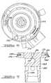
- Scroll compressor 10which includes the unique capacity control system in accordance with the present invention and which is designated generally by the reference numeral 10.
- Scroll compressor 10is generally of the type described in Assignee's U.S. Patent No. 5,102,316, the disclosure of which is incorporated herein by reference.
- Scroll compressor 10comprises an outer shell 12 within which is disposed a driving motor including a stator 14 and a rotor 16, a crankshaft 18 to which rotor 16 is secured, an upper bearing housing 20 and a lower bearing housing (not shown) for rotatably supporting crankshaft 18 and a compressor assembly 24.
- Compressor assembly 24includes an orbiting scroll member 26 supported on upper bearing housing 20 and drivingly connected to crankshaft 18 via a crankpin 28 and a drive bushing 30.
- a non-orbiting scroll member 32is positioned in meshing engagement with orbiting scroll member 26 and is axially movably secured to upper bearing housing 20 by means of a plurality of bolts 34 and associated sleeve members 36.
- An Oldham coupling 38is provided which cooperates with scroll members 26 and 32 to prevent relative rotation therebetween.
- a partition plate 40is provided adjacent the upper end of shell 12 and serves to divide the interior of shell 12 into a discharge chamber 42 at the upper end thereof and a suction chamber 44 at the lower end thereof.
- suction gasis drawn into suction chamber 44 of shell 12 via a suction fitting 46. From suction chamber 44, suction gas is sucked into compressor 24 through an inlet 48 provided in non-orbiting scroll member 32.
- the intermeshing scroll wraps provided on scroll members 26 and 32define moving pockets of gas which progressively decrease in size as they move radially inwardly as a result of the orbiting motion of scroll member 26 thus compressing the suction gas entering via inlet 48.
- the compressed gasis then discharged into discharge chamber 42 through a hub 50 provided in scroll member 36 and a passage 52 formed in partition 40.
- a pressure responsive discharge valve 54is preferably provided seated within hub 50.
- Non-orbiting scroll member 32is also provided with an annular recess 56 formed in the upper surface thereof.
- a floating seal 58is disposed within recess 56 and is biased by intermediate pressurized gas against partition 40 to seal suction chamber 44 from discharge chamber 42.
- a passage 60extends through non-orbiting scroll member 32 to supply the intermediate pressurized gas to recess 56.
- a capacity control system 66is shown in association with compressor 10.
- Control system 66includes a discharge fitting 68, a piston 70, a shell fitting 72, a three-way solenoid valve 74, a control module 76 and a sensor array 78 having one or more appropriate sensors.
- Discharge fitting 68is threadingly received or otherwise secured within hub 50.
- Discharge fitting 68defines an internal cavity 80 and a plurality of discharge passages 82.
- Discharge valve 54is disposed within cavity 80.
- discharge fitting 68is assembled to piston 70 by first aligning a plurality of tabs 84 on discharge fitting 68 with a matching plurality of slots 86 formed in piston 70. Discharge fitting 68 is then rotated to the position shown in Figure 3 to misalign tabs 84 with slots 86. An alignment pin 88 maintains the misalignment between tabs 84 and slots 86 while a coil spring 90 biases the two components together.
- Shell fitting 72is sealingly secured to shell 12 and slidingly receives piston 70.
- Piston 70 and shell fitting 72define a pressure chamber 92.
- Pressure chamber 92is fluidically connected to solenoid 74 by a tube 94.
- Solenoid valve 74is also in fluid communication with discharge chamber 42 through a tube 96 and it is in fluid communication with suction fitting 46 and thus suction chamber 44 through a tube 98.
- a seal 100is located between piston 70 and shell fitting 72.
- the combination of piston 70, seal 100 and shell fitting 72provides a self-centering sealing system to provide accurate alignment between piston 70 and shell fitting 72.
- solenoid valve 74is deactivated (or it is actuated) by control module 76 to the position shown in Figure 1. In this position, discharge chamber 42 is in direct communication with chamber 92 through tube 96, solenoid valve 74 and tube 94.
- the pressurized fluid at discharge pressure within chambers 42 and 92will act against opposite sides of piston 70 thus allowing for the normal biasing of non-orbiting scroll member 32 towards orbiting scroll member 26 as shown in Figure 1 to sealingly engage the axial ends of each scroll member with the respective end plate of the opposite scroll member.
- the axial sealing of the two scroll members 26 and 32causes compressor 24 to operate at 100% capacity.
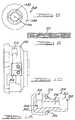
- solenoid valve 74In order to unload compressor 24, solenoid valve 74 will be actuated (or it is deactuated) by control module 76 to the position shown in Figure 2. In this position, suction chamber 44 is in direct communication with chamber 92 through suction fitting 46, tube 98, solenoid valve 74 and tube 94. With the discharge pressure pressurized fluid released to suction from chamber 92, the pressure differences on opposite sides of piston 70 will move non-orbiting scroll member 32 upward as shown in Figure 2 to separate the axial ends of the tips of each scroll member with its respective end plate to create a gap 102 which allows the higher pressurized pockets to bleed to the lower pressurized pockets and eventually to suction chamber 44.
- a wave spring 104which is illustrated in Figure 9 maintains the sealing relationship between floating seal 58 and partition 40 during the modulation of non-orbiting scroll member 32.
- the creation of gap 102will substantially eliminate continued compression of the suction gas.
- discharge valve 54will move to its closed position thereby preventing the backflow of high pressurized fluid from discharge chamber 42 or the downstream refrigeration system.
- solenoid valve 74will be deactuated (or it will be actuated) to the position shown in Figure 1 in which fluid communication between chamber 92 and discharge chamber 42 is again created. This again allows fluid at discharge pressure to react against piston 70 to axially engage scroll members 26 and 32. The axial sealing engagement recreates the compressing action of compressor 24.
- Control module 76is in communication with sensor array 78 to provide the required information for control module 76 to determine the degree of unloading required for the particular conditions of the refrigeration system including scroll compressor 10 existing at that time. Based upon this information, control module 76 will operate solenoid valve 74 in a pulsed width modulation mode to alternately place chamber 92 in communication with discharge chamber 42 and suction chamber 44. The frequency with which solenoid 74 is operated in the pulsed width modulated mode will determine the percent capacity of operation of compressor 24. As the sensed conditions change, control module 76 will vary the frequency of operation for solenoid valve 74 and thus the relative time periods at which compressor 24 is operated in a loaded and unloaded condition. The varying of the frequency of operation of solenoid valve 74 can cause the operation of compressor between fully loaded or 100% capacity and completely unloaded or 0% capacity or at any of an infinite number of settings in between in response to system demands.
- Capacity control system 166is also shown in association with compressor 10. Capacity control system 166 is similar to capacity control system 66 but it uses a two-way solenoid valve 174 instead of three-way solenoid valve 74. Control system 166 includes discharge filling 68, a piston 170, shell fitting 72, solenoid valve 174, control module 76 and sensor array 78.
- Piston 170is identical to piston 70 with the exception that piston 170 defines a passageway 106 and an orifice 108 which extend between pressure chamber 92 and discharge chamber 42.
- the incorporation of passageway 106 and orifice 108allows the use of two-way solenoid 174 instead of three-way solenoid 74 and the elimination of tube 96.
- Seal 100is located between piston 170 and seal fitting 72 to provide for the self-aligning sealing system for piston 170 and fitting 72.
- Solenoid 174operates in a manner similar to solenoid 74. Pressure chamber 92 is fluidically connected to solenoid 174 by tube 94. Solenoid valve 174 is also in fluid communication with suction fitting 46 and thus suction chamber 44 by tube 98.
- solenoid valve 174is deactivated (or it is activated) by control module 76 to block fluid flow between tubes 94 and tube 98.
- chamber 92is in communication with discharge chamber 42 through passageway 106 and orifice 108.
- the pressurized fluid at discharge pressure within chambers 42 and 92will act against opposite sides of piston 170 thus allowing for the normal biasing of non-orbiting scroll member 32 towards orbiting scroll member 26 to sealingly engage the axial ends of each scroll member with the respective end plate of the opposite scroll member.
- the axial sealing of the two scroll members 26 and 32causes compressor 24 to operate at 100% capacity.
- solenoid valve 174will be actuated (or it will be deactuated) by control module 76 to the position shown in Figure 4. In this position, suction chamber 44 is in direct communication with chamber 92 through suction fitting 46, tube 98, solenoid valve 174 and tube 94. With the discharge pressure pressurized fluid released to suction from chamber 92, the pressure differences on opposite sides of piston 170 will move non-orbiting scroll member 32 upward to separate the axial end of the tips of each scroll member with its respective end plate and the higher pressurized pockets will bleed to the lower pressurized pockets and eventually to suction chamber 44. Orifice 108 is incorporated to control the flow of discharge gas between discharge chamber 42 and chamber 92.
- Wave spring 104is also incorporated in this embodiment to maintain the sealing relationship between floating seal 58 and partition 40 during modulation of non-orbiting scroll member 32.
- gap 102When gap 102 is created the continued compression of the suction gas will be eliminated.
- discharge valve 54When this unloading occurs, discharge valve 54 will move to its closed position thereby preventing the backflow of high pressurized fluid from discharge chamber 42 on the downstream refrigeration system.
- solenoid valve 174When compression of the suction gas is to be resumed, solenoid valve 174 will be deactuated (or it will be actuated) to again block fluid flow between tubes 94 and 98 allowing chamber 92 to be pressurized by discharge chamber 42 through passageway 106 and orifice 108. Similar to the embodiment shown in Figures 1-3, control module 76 is in communication with sensor array 78 to provide the required information for control module 76 to determine the degree of unloading required and thus the frequency with which solenoid valve 174 is operated in the pulsed width modulation mode.
- FIG. 5there is shown a scroll compressor which includes a unique capacity control system in accordance with another embodiment of the present invention and which is designated generally by the reference numeral 210.
- Scroll compressor 210comprises an outer shell 212 within which is disposed a driving motor including a stator 214 and a rotor 216, a crankshaft 218 to which rotor 216 is secured, an upper bearing housing 220 and a lower bearing housing 222 for rotatably supporting crankshaft 218 and a compressor assembly 224.
- a driving motorincluding a stator 214 and a rotor 216, a crankshaft 218 to which rotor 216 is secured, an upper bearing housing 220 and a lower bearing housing 222 for rotatably supporting crankshaft 218 and a compressor assembly 224.
- Compressor assembly 224includes an orbiting scroll member 226 supported on upper bearing housing 220 and drivingly connected to crankshaft 218 via a crankpin 228 and a drive bushing 230.
- a non-orbiting scroll member 232is positioned in meshing engagement with orbiting scroll member 226 and is axially movably secured to upper bearing housing 220 by means of a plurality of bolts (not shown) and associated sleeve members (not shown).
- An Oldham coupling 238is provided which cooperates with scroll members 226 and 232 to prevent relative rotation therebetween.
- a partition plate 240is provided adjacent the upper end of shell 212 and serves to divide the interior of shell 212 into a discharge chamber 242 at the upper end thereof and a suction chamber 244 at the lower end thereof.
- suction gasis drawn into suction chamber 244 of shell 212 via a suction fitting 246. From suction chamber 244, suction gas is sucked into compressor 224 through an inlet 248 provided in non-orbiting scroll member 232.
- the intermeshing scroll wraps provided on scroll members 226 and 232define moving pockets of gas which progressively decrease in size as they move radially inwardly as a result of the orbiting motion of scroll member 226 thus compressing the suction gas entering via inlet 248.
- the compressed gasis then discharged into discharge chamber 242 via a discharge port 250 provided in scroll member 236 and a passage 252 formed in partition 240.
- a pressure responsive discharge valve 254is preferably provided seated within discharge port 250.
- Non-orbiting scroll member 232is also provided with an annular recess 256 formed in the upper surface thereof.
- a floating seal 258is disposed within recess 256 and is biased by intermediate pressurized gas against partition 240 to seal suction chamber 244 from discharge chamber 246.
- a passage 260extends through non-orbiting scroll member 232 to supply the intermediate pressurized gas to recess 256.
- a capacity control system 266is shown in association with compressor 210.
- Control system 266includes a discharge fitting 268, a piston 270, a shell fitting 272, solenoid valve 174, control module 76 and sensor array 78 having one or more appropriate sensors.
- Discharge fitting 268is threadingly received or otherwise secured within discharge port 250.
- Discharge fitting 268defines an internal cavity 280 and a plurality of discharge passages 282.
- Discharge valve 254is disposed below fitting 268 and below cavity 280.
- Discharge fitting 268defines an annular flange 284. Seated against flange 284 is a lip seal 286 and a floating retainer 288. Piston 270 is press fit or otherwise secured to discharge fitting 268 and piston 270 defines an annular flange 290 which sandwiches seal 286 and retainer 288 between flange 290 and flange 284. Discharge fitting 268 defines passageway 106 and orifice 108 which extends through discharge fitting 268 to fluidically connect discharge chamber 242 with a pressure chamber 292 defined by discharge fitting 268, piston 270, seal 286, retainer 288 and shell 212.
- Shell fitting 272is secured within a bore defined by shell 212 and slidingly receives the assembly of discharge fitting 268, piston 270, seal 286 and retainer 288.
- Pressure chamber 292is fluidically connected to solenoid 174 by tube 94 and with suction fitting 246 and thus suction chamber 244 through tube 98 in a manner similar to that described above for control system 166.
- the combination of piston 270, seal 286 and floating retainer 288provides a self-centering sealing system to provide accurate alignment with the internal bore of shell fitting 272.
- Seal 286 and floating retainer 288include sufficient radial compliance such that any misalignment between the internal bore of fitting 272 and the internal bore of discharge port 250 within which discharge fitting 268 is secured is accommodated by seal 286 and floating retainer 288.
- solenoid valve 174is deactivated (or it is activated) by control module 76 to block fluid flow between tubes 94 and tube 98.
- chamber 292is in communication with discharge chamber 242 through passageway 106 and orifice 108.
- the pressurized fluid at discharge pressure within chambers 242 and 292will act against opposite sides of piston 270 thus allowing for the normal biasing of non-orbiting scroll member 232 towards orbiting scroll member 226 to sealingly engage the axial ends of each scroll member with the respective end plate of the opposite scroll member.
- the axial sealing of the two scroll members 226 and 232causes compressor 224 to operate at 100% capacity.
- solenoid valve 174In order to unload compressor 224, solenoid valve 174 will be actuated (or it will be deactuated) by control module 76 to the position shown in Figure 4. In this position, suction chamber 244 is in direct communication with chamber 292 through suction fitting 246, tube 98, solenoid valve 174 and tube 94. With the discharge pressure pressurized fluid released to suction from chamber 292, the pressure difference on opposite sides of piston 270 will move non-orbiting scroll member 232 upward to separate the axial end of the tips of each scroll member with its respective end plate and the higher pressurized pockets will bleed to the lower pressurized pockets and eventually to suction chamber 244. Orifice 108 is incorporated to control the flow of discharge gas between discharge chamber 242 and chamber 292.
- Wave spring 104is also incorporated in this embodiment to maintain the sealing relationship between floating seal 258 and partition 240 during modulation of non-orbiting scroll member 232.
- gap 102When gap 102 is created the continued compression of the suction gas will be eliminated.
- discharge valve 254When this unloading occurs, discharge valve 254 will move to its closed position thereby preventing the backflow of high pressurized fluid from discharge chamber 242 on the downstream refrigeration system.
- solenoid valve 174When compression of the suction gas is to be resumed, solenoid valve 174 will be deactuated (or it will be actuated) to again block fluid flow between tubes 94 and 98 allowing chamber 292 to be pressurized by discharge chamber 242 through passageway 106 and orifice 108. Similar to the embodiment shown in Figures 1-3, control module 76 is in communication with sensor array 78 to provide the required information for control module 76 to determine the degree of unloading required and thus the frequency with which solenoid valve 174 is operated in the pulsed width modulation mode.
- Compressor 210includes the capability of having fluid injected into the intermediate pressurized moving chambers at a point intermediate suction chamber 244 and discharge chamber 242.
- a fluid injection fitting 310extends through shell 212 and is fluidically connected to an injection tube 312 which is in turn fluidically connected to an injection fitting 314 secured to non-orbiting scroll member 232.
- Non-orbiting scroll member 232defines a pair of radial passages 316 each of which extend between injection fitting 314 and a pair of axial passages 318.
- Axial passages 318are open to the moving chambers on opposite sides of non-orbiting scroll member 232 of compressor 224 to inject the fluid into these moving chambers as required by a control system as is well known in the art.
- Fitting 310comprises an internal portion 320, and an external portion 322.
- Internal portion 320includes an L-shaped passage 324 which sealingly receives injection tube 312 at one end.
- External portion 322extends from the outside of shell 212 to the inside of shell 212 where it is unitary or integral with internal portion 320.
- a welding or brazing attachment 326secures and seals fitting 310 to shell 212.
- External portion 322defines a bore 330 which is an extension of L-shaped passage 324.
- External portion 322also defines a cylindrical bore 332 to which the tubing of the refrigeration system is secured.
- Figure 14illustrates a vapor injection system which provides the fluid for the fluid injection system of compressor 210.
- Compressor 210is shown in a refrigeration system which includes a condenser 350, a first expansion valve or throttle 352, a flash tank or an economizer 354, a second expansion valve or throttle 356, an evaporator 358 and a series of piping 360 interconnecting the components as shown in Figure 14.
- Compressor 210is operated by the motor to compress the refrigerant gas.
- the compressed gasis then liquified by condenser 350.
- the liquified refrigerantpasses through expansion valve 352 and expands in flash tank 354 where it is separated into gas and liquid.
- the gaseous refrigerantfurther passes through piping 362 to be introduced into compressor 210 through fitting 310.
- the remaining liquid refrigerantfurther expands in expansion valve 356, is then vaporized in evaporator 358 and is again taken into compressor 210.
- flash tank 354allows the capacity of the compressor to increase above the fixed capacity of compressor 210.
- the capacity of the compressorcan be increased by approximately 20% to provide a compressor with 120% of its capacity as shown in the graph in Figure 16.
- a solenoid valve 364is positioned within piping 362. The amount of percent increase in the capacity of compressor 210 can be controlled by operating solenoid valve 364 in a pulse width modulation mode. Solenoid valve 364 when operated in a pulse width modulation mode in combination with capacity control system 266 of compressor 210 allows the capacity of compressor 210 to be positioned anywhere along the line shown in Figure 16.
- FIG 15illustrates a refrigerant system schematic in accordance with another embodiment of the present invention.
- the refrigerant system shown in Figure 15is the same as the refrigerant system shown in Figure 14 except that flash tank 354 has been replaced by a heat exchanger 354'.
- Compressor 210is operated by the motor to compress the refrigerant gas.
- the compressed gasis then liquified by condenser 350.
- the liquified refrigerantis then routed to the liquid side of heat exchanger 354' while a second portion of the liquified refrigerant passes through expansion valve 352 and then is routed to the vapor side of heat exchanger 354' in a gas and liquid state.
- the portion of refrigerant passing through expansion valve 352is heated by the portion of refrigerant passing directly through heat exchanger to provide the vapor for injecting into compressor 210.
- This gaseous refrigerantthen passes through piping 362 to be introduced into compressor 210 through fitting 310.
- the liquid refrigerant passing directly through heat exchanger 354'expands in expansion valve 356 and is then vaporized in evaporator 358 to again be taken into the suction side of compressor 210.
- solenoid valve 364is positioned within piping 362 to allow the capacity of compressor 210 to be positioned anywhere along the line shown in Figure 16 when used in combination with capacity control system 266.
Landscapes
- Engineering & Computer Science (AREA)
- Mechanical Engineering (AREA)
- General Engineering & Computer Science (AREA)
- Physics & Mathematics (AREA)
- Fluid Mechanics (AREA)
- Rotary Pumps (AREA)
- Applications Or Details Of Rotary Compressors (AREA)
- Compressors, Vaccum Pumps And Other Relevant Systems (AREA)
Abstract
Description
Claims (31)
- A scroll-type machine comprising:a first scroll member having a first end plate and a first spiral wrapextending therefrom;a second scroll member having a second end plate and a second spiralwrap extending therefrom, said first and second scroll members being positioned withsaid first and second spiral wraps interleaved with each other;a drive member for causing said scroll members to orbit relative to oneanother whereby said spiral wraps will create pockets of progressively changing volumebetween a suction pressure zone and a discharge pressure zone;said first and second scroll members being movable between a firstrelationship in which sealing surfaces of said first and second scroll members are insealing relationship to close off said pockets and a second relationship wherein at leastone of said sealing surfaces of said first and second scroll members are spaced apartto define a leakage path between said pockets; anda fluid operated piston secured to said first scroll, said piston beingactuatable to apply a force to said first scroll to move said first scroll between said firstrelationship where said scroll machine operates at substantially full capacity and saidsecond relationship in which said scroll machine operates at substantially zero capacity.
- The scroll-type machine according to claim 1, further comprising a fluidpressure chamber operative to apply said force to said fluid operated piston.
- The scroll-type machine according to claim 2, wherein said force acts inan axial direction.
- The scroll-type machine according to claim 3, further comprising a firstpassage for supplying a pressurized fluid from said scroll-type machine to said pressurechamber.
- The scroll-type machine according to claim 4, further comprising a valvefor controlling flow through said first passage, said valve being operative to vent saidpressurized fluid from said pressure chamber to thereby enable said first and secondscrolls to move between said first and second relationships.
- The scroll-type machine according to claim 5, further comprising a controlmodule in communication with said valve.
- The scroll-type machine according to claim 6, further comprising at leastone sensor in communication with said control module, said control module beingoperative to control said valve in response to a signal from said sensor.
- The scroll-type machine according to claim 4, further comprising a secondpassage for venting said pressurized fluid from said pressure chamber.
- The scroll-type machine according to claim 1, wherein said scroll-typemachine includes a shell, said fluid operated piston being slidingly received within afitting secured to said shell.
- The scroll-type machine according to claim 9, wherein said piston andsaid fitting define a pressure chamber.
- The scroll-type machine according to claim 10, wherein said pressurechamber is in communication with a suction chamber defined by said shell.
- The scroll-type machine according to claim 11, further comprising a valvedisposed between said pressure chamber and said suction chamber.
- The scroll-type machine according to claim 12, wherein said pressurechamber is in communication with a discharge chamber defined by said shell.
- The scroll-type machine according to claim 11, further comprising a valvedisposed between said pressure chamber and both said suction chamber and saiddischarge chamber.
- The scroll-type machine according to claim 14, further comprising a valvedisposed between said pressure chamber and said suction chamber.
- A scroll-type machine comprising:a first scroll member having a first end plate and a first spiral wrapextending therefrom;a second scroll member having a second end plate and a second spiralwrap extending therefrom, said first and second scroll members being positioned withsaid first and second spiral wraps interleaved with each other;a drive member for causing said scroll members to orbit relative to oneanother whereby said spiral wraps will create pockets of progressively changing volumebetween a suction pressure zone and a discharge pressure zone;said first and second scroll members being movable between a firstrelationship in which sealing surfaces of said first and second scroll members are insealing relationship to close off said pockets and a second relationship wherein at leastone of said sealing surfaces of said first and second scroll members are spaced apartto define a leakage path between said pockets;a fluid operated piston secured to said first scroll and slidingly receivedwithin a bore defined by said shell, said piston being actuatable to apply a force to saidfirst scroll to move said first scroll between said first relationship where said scrollmachine operates at substantially full capacity and said second relationship in which saidscroll machine operates at substantially zero capacity; anda radially compliant sealing system disposed between said piston andsaid bore defined by said shell.
- The scroll-type machine according to Claim 16, further comprising anannular fitting disposed between said shell and said piston, said radially complaintsealing system being disposed between said piston and said fitting.
- The scroll-type machine according to claim 16, wherein said radiallycomplaint sealing system includes a lip seal.
- The scroll-type machine according to claim 16 or claim 18, wherein saidradially complaint sealing system includes a floating retainer.
- A scroll-type machine comprising:a first scroll member having a first end plate and a first spiral wrapextending from said first end plate;a second scroll member having a second end plate and a second spiralwrap extending from said second end plate, said first and second scroll members beingpositioned with said first and second spiral wraps interleaved with each other;a drive member for causing said scroll members to orbit relative to oneanother whereby said spiral wraps will create pockets of progressively changing volumebetween a suction pressure zone and a discharge pressure zone;a mechanism for moving said first and second scroll members betweena first relationship where sealing surfaces of said first and second scroll members arein sealing relationship to close off said pockets and a second relationship where at leastone of said sealing surfaces of said first and second scroll members are spaced apartto define a leak path between said pockets; anda fluid injection system associated with one of said scroll members forinjecting a fluid into at least one of said pockets.
- The scroll-type machine according to claim 20, wherein said mechanismis operated in a pulse width modulation mode.
- The scroll-type machine according to claim 20, wherein said mechanismincludes a solenoid valve.
- The scroll-type machine according to claim 20, wherein said mechanismincludes a fluid operated piston secured to said first scroll, said piston being activatable to apply a force to said first scroll to move said first scroll between said first and secondrelationships.
- The scroll-type machine according to claim 1 or claim 23, wherein saiddrive member continues to operate when said first scroll member is in said secondrelationship.
- The scroll-type machine according to claim 24, wherein said scroll-typemachine includes a discharge flow path for conducting compressed fluid from said scroll-typemachine and a check valve located within said flow path to prevent reverse flow ofsaid compressed fluid.
- The scroll-type machine according to claim 1 or claim 23, wherein saidfluid operated piston is operated in a time pulsed manner to modulate the capacity ofsaid scroll-type machine.
- The scroll-type machine according to claim 20 or claim 26, wherein saidfluid injection system includes a solenoid valve for controlling flow of said fluid to saidone of said scroll members.
- A scroll-type machine comprising:a first scroll member having a first end plate and a first spiral wrapextending from said first end plate;a second scroll member having a second end plate and a second spiralwrap extending from said second end plate, said first and second scroll members beingpositioned with said first and second spiral wraps interleaved with each other;a drive member for causing said scroll members to orbit relative to oneanother whereby said spiral wraps will create pockets of progressively changing volumebetween a suction pressure zone and a discharge pressure zone; anda vapor injection system associated with one of said scroll members forinjecting a vapor into at least one of said pockets, said vapor injection system includinga valve for controlling said vapor being injected into said at least one of said pockets.
- The scroll-type machine according to any one of claims 5, 12, 15 and 28,wherein said valve is a solenoid valve.
- The scroll-type machine according to any one of claims 22, 27 and 29,wherein said solenoid valve is operated in a pulse width modulation mode.
- The scroll-type machine according to any one of claims 21, 23 and 30,wherein said fluid being injected into one of said pockets is a vapor.
Priority Applications (1)
| Application Number | Priority Date | Filing Date | Title |
|---|---|---|---|
| EP05023776.7AEP1619389B1 (en) | 1999-09-21 | 2000-09-20 | Scroll compressor capacity control |
Applications Claiming Priority (2)
| Application Number | Priority Date | Filing Date | Title |
|---|---|---|---|
| US401343 | 1999-09-21 | ||
| US09/401,343US6213731B1 (en) | 1999-09-21 | 1999-09-21 | Compressor pulse width modulation |
Related Child Applications (1)
| Application Number | Title | Priority Date | Filing Date |
|---|---|---|---|
| EP05023776.7ADivisionEP1619389B1 (en) | 1999-09-21 | 2000-09-20 | Scroll compressor capacity control |
Publications (3)
| Publication Number | Publication Date |
|---|---|
| EP1087142A2true EP1087142A2 (en) | 2001-03-28 |
| EP1087142A3 EP1087142A3 (en) | 2002-06-26 |
| EP1087142B1 EP1087142B1 (en) | 2006-03-15 |
Family
ID=23587368
Family Applications (2)
| Application Number | Title | Priority Date | Filing Date |
|---|---|---|---|
| EP05023776.7AExpired - LifetimeEP1619389B1 (en) | 1999-09-21 | 2000-09-20 | Scroll compressor capacity control |
| EP00308176AExpired - LifetimeEP1087142B1 (en) | 1999-09-21 | 2000-09-20 | Scroll compressor capacity control |
Family Applications Before (1)
| Application Number | Title | Priority Date | Filing Date |
|---|---|---|---|
| EP05023776.7AExpired - LifetimeEP1619389B1 (en) | 1999-09-21 | 2000-09-20 | Scroll compressor capacity control |
Country Status (10)
| Country | Link |
|---|---|
| US (2) | US6213731B1 (en) |
| EP (2) | EP1619389B1 (en) |
| JP (1) | JP4782915B2 (en) |
| KR (2) | KR100637011B1 (en) |
| CN (3) | CN100353066C (en) |
| AU (1) | AU768192B2 (en) |
| BR (1) | BR0004334A (en) |
| DE (1) | DE60032033T2 (en) |
| ES (1) | ES2257270T3 (en) |
| MX (1) | MXPA00009021A (en) |
Cited By (58)
| Publication number | Priority date | Publication date | Assignee | Title |
|---|---|---|---|---|
| EP1241417A1 (en)* | 2001-03-16 | 2002-09-18 | Copeland Corporation | Digital controller for scroll compressor condensing unit |
| EP1253324A3 (en)* | 2001-04-25 | 2003-05-14 | Copeland Corporation | Diagnostic system for a hermetic scroll compressor |
| EP1253323A3 (en)* | 2001-04-25 | 2003-06-04 | Copeland Corporation | Hermetic compressors |
| EP1331396A3 (en)* | 2002-01-24 | 2003-09-17 | Copeland Corporation | Scroll compressor with vapor injection |
| DE102005000896A1 (en)* | 2004-11-11 | 2006-05-24 | Lg Electronics Inc. | Scroll compressor`s capacity varying apparatus for e.g. refrigerator, has sealing varying mechanism changing sealing region of orbiting and fixed scroll wraps based on change in pressure applied to back of orbiting scroll |
| EP1382854A3 (en)* | 2002-07-15 | 2006-05-24 | Copeland Corporation | Dual volume-ratio scroll machine |
| EP1941219A4 (en)* | 2005-10-26 | 2010-08-25 | Carrier Corp | Refrigerant system with pulse width modulated components and variable speed compressor |
| US8065886B2 (en) | 2001-05-03 | 2011-11-29 | Emerson Retail Services, Inc. | Refrigeration system energy monitoring and diagnostics |
| WO2011134030A3 (en)* | 2010-04-26 | 2012-07-19 | Whirlpool S.A. | Cooling system of a refrigerator and suction system for a compressor fluid |
| EP2047192A4 (en)* | 2006-08-01 | 2012-12-26 | Carrier Corp | Modular compressor-valve design for refrigerant system |
| AU2010212403B2 (en)* | 2000-10-16 | 2013-01-10 | Emerson Climate Technologies, Inc | Dual volume-ratio scroll machine |
| US8473106B2 (en) | 2009-05-29 | 2013-06-25 | Emerson Climate Technologies Retail Solutions, Inc. | System and method for monitoring and evaluating equipment operating parameter modifications |
| US8485789B2 (en) | 2007-05-18 | 2013-07-16 | Emerson Climate Technologies, Inc. | Capacity modulated scroll compressor system and method |
| US8495886B2 (en) | 2001-05-03 | 2013-07-30 | Emerson Climate Technologies Retail Solutions, Inc. | Model-based alarming |
| US8700444B2 (en) | 2002-10-31 | 2014-04-15 | Emerson Retail Services Inc. | System for monitoring optimal equipment operating parameters |
| EP2806165A1 (en)* | 2013-05-22 | 2014-11-26 | Obrist Engineering GmbH | Scroll compressor and CO2 vehicle air conditioner with a scroll compressor |
| US8964338B2 (en) | 2012-01-11 | 2015-02-24 | Emerson Climate Technologies, Inc. | System and method for compressor motor protection |
| US8974573B2 (en) | 2004-08-11 | 2015-03-10 | Emerson Climate Technologies, Inc. | Method and apparatus for monitoring a refrigeration-cycle system |
| EP2679930A4 (en)* | 2011-02-22 | 2015-04-29 | Hitachi Ltd | REFRIGERATION CYCLE APPARATUS |
| CN104632617A (en)* | 2013-11-11 | 2015-05-20 | Lg电子株式会社 | Scroll compressor and air conditioner including the same |
| US9121407B2 (en) | 2004-04-27 | 2015-09-01 | Emerson Climate Technologies, Inc. | Compressor diagnostic and protection system and method |
| US9140728B2 (en) | 2007-11-02 | 2015-09-22 | Emerson Climate Technologies, Inc. | Compressor sensor module |
| EP2940306A1 (en)* | 2014-05-02 | 2015-11-04 | LG Electronics Inc. | Scroll compressor |
| US9285802B2 (en) | 2011-02-28 | 2016-03-15 | Emerson Electric Co. | Residential solutions HVAC monitoring and diagnosis |
| US9310439B2 (en) | 2012-09-25 | 2016-04-12 | Emerson Climate Technologies, Inc. | Compressor having a control and diagnostic module |
| US9310094B2 (en) | 2007-07-30 | 2016-04-12 | Emerson Climate Technologies, Inc. | Portable method and apparatus for monitoring refrigerant-cycle systems |
| US9494157B2 (en) | 2012-11-30 | 2016-11-15 | Emerson Climate Technologies, Inc. | Compressor with capacity modulation and variable volume ratio |
| US9512840B2 (en) | 2013-05-22 | 2016-12-06 | Obrist Engineering Gmbh | Scroll-type compressor and CO2 vehicle air conditioning system having a scroll-type compressor |
| US9551504B2 (en) | 2013-03-15 | 2017-01-24 | Emerson Electric Co. | HVAC system remote monitoring and diagnosis |
| US9638436B2 (en) | 2013-03-15 | 2017-05-02 | Emerson Electric Co. | HVAC system remote monitoring and diagnosis |
| US9651043B2 (en) | 2012-11-15 | 2017-05-16 | Emerson Climate Technologies, Inc. | Compressor valve system and assembly |
| US9765979B2 (en) | 2013-04-05 | 2017-09-19 | Emerson Climate Technologies, Inc. | Heat-pump system with refrigerant charge diagnostics |
| US9790940B2 (en) | 2015-03-19 | 2017-10-17 | Emerson Climate Technologies, Inc. | Variable volume ratio compressor |
| US9803902B2 (en) | 2013-03-15 | 2017-10-31 | Emerson Climate Technologies, Inc. | System for refrigerant charge verification using two condenser coil temperatures |
| US9823632B2 (en) | 2006-09-07 | 2017-11-21 | Emerson Climate Technologies, Inc. | Compressor data module |
| US9885507B2 (en) | 2006-07-19 | 2018-02-06 | Emerson Climate Technologies, Inc. | Protection and diagnostic module for a refrigeration system |
| US9989057B2 (en) | 2014-06-03 | 2018-06-05 | Emerson Climate Technologies, Inc. | Variable volume ratio scroll compressor |
| US10041713B1 (en) | 1999-08-20 | 2018-08-07 | Hudson Technologies, Inc. | Method and apparatus for measuring and improving efficiency in refrigeration systems |
| US10066622B2 (en) | 2015-10-29 | 2018-09-04 | Emerson Climate Technologies, Inc. | Compressor having capacity modulation system |
| US10094380B2 (en) | 2012-11-15 | 2018-10-09 | Emerson Climate Technologies, Inc. | Compressor |
| US10378540B2 (en) | 2015-07-01 | 2019-08-13 | Emerson Climate Technologies, Inc. | Compressor with thermally-responsive modulation system |
| EP1886021B1 (en)* | 2005-05-24 | 2019-08-21 | Emerson Climate Technologies, Inc. | Control and protection system for a variable capacity compressor |
| US10753352B2 (en) | 2017-02-07 | 2020-08-25 | Emerson Climate Technologies, Inc. | Compressor discharge valve assembly |
| US10801495B2 (en) | 2016-09-08 | 2020-10-13 | Emerson Climate Technologies, Inc. | Oil flow through the bearings of a scroll compressor |
| US10890186B2 (en) | 2016-09-08 | 2021-01-12 | Emerson Climate Technologies, Inc. | Compressor |
| WO2021007528A1 (en) | 2019-07-11 | 2021-01-14 | Emerson Climate Technologies, Inc. | Compressor having capacity modulation |
| US10954940B2 (en) | 2009-04-07 | 2021-03-23 | Emerson Climate Technologies, Inc. | Compressor having capacity modulation assembly |
| US10962008B2 (en) | 2017-12-15 | 2021-03-30 | Emerson Climate Technologies, Inc. | Variable volume ratio compressor |
| US10995753B2 (en) | 2018-05-17 | 2021-05-04 | Emerson Climate Technologies, Inc. | Compressor having capacity modulation assembly |
| US11022119B2 (en) | 2017-10-03 | 2021-06-01 | Emerson Climate Technologies, Inc. | Variable volume ratio compressor |
| GB2592657A (en)* | 2020-03-05 | 2021-09-08 | Edwards Ltd | Scroll pump apparatus and method |
| US11655813B2 (en) | 2021-07-29 | 2023-05-23 | Emerson Climate Technologies, Inc. | Compressor modulation system with multi-way valve |
| US11846287B1 (en) | 2022-08-11 | 2023-12-19 | Copeland Lp | Scroll compressor with center hub |
| US11965507B1 (en) | 2022-12-15 | 2024-04-23 | Copeland Lp | Compressor and valve assembly |
| US12163523B1 (en) | 2023-12-15 | 2024-12-10 | Copeland Lp | Compressor and valve assembly |
| US12173708B1 (en) | 2023-12-07 | 2024-12-24 | Copeland Lp | Heat pump systems with capacity modulation |
| US12259163B2 (en) | 2022-06-01 | 2025-03-25 | Copeland Lp | Climate-control system with thermal storage |
| US12416308B2 (en) | 2022-12-28 | 2025-09-16 | Copeland Lp | Compressor with shutdown assembly |
Families Citing this family (105)
| Publication number | Priority date | Publication date | Assignee | Title |
|---|---|---|---|---|
| US6047557A (en)* | 1995-06-07 | 2000-04-11 | Copeland Corporation | Adaptive control for a refrigeration system using pulse width modulated duty cycle scroll compressor |
| US6206652B1 (en) | 1998-08-25 | 2001-03-27 | Copeland Corporation | Compressor capacity modulation |
| US6047556A (en)* | 1997-12-08 | 2000-04-11 | Carrier Corporation | Pulsed flow for capacity control |
| US6478550B2 (en)* | 1998-06-12 | 2002-11-12 | Daikin Industries, Ltd. | Multi-stage capacity-controlled scroll compressor |
| US6213731B1 (en)* | 1999-09-21 | 2001-04-10 | Copeland Corporation | Compressor pulse width modulation |
| JP4639413B2 (en)* | 1999-12-06 | 2011-02-23 | ダイキン工業株式会社 | Scroll compressor and air conditioner |
| US6558126B1 (en)* | 2000-05-01 | 2003-05-06 | Scroll Technologies | Compressor utilizing low volt power tapped from high volt power |
| WO2001094857A1 (en)* | 2000-06-07 | 2001-12-13 | Samsung Electronics Co., Ltd. | Control system for starting of air conditioner and control method thereof |
| US6412293B1 (en)* | 2000-10-11 | 2002-07-02 | Copeland Corporation | Scroll machine with continuous capacity modulation |
| US6615598B1 (en)* | 2002-03-26 | 2003-09-09 | Copeland Corporation | Scroll machine with liquid injection |
| US6672090B1 (en)* | 2002-07-15 | 2004-01-06 | Copeland Corporation | Refrigeration control |
| US6792767B1 (en) | 2002-10-21 | 2004-09-21 | Aaon Inc. | Controls for air conditioner |
| CN100344881C (en)* | 2003-06-17 | 2007-10-24 | 乐金电子(天津)电器有限公司 | Noise reducing device for vortex type compressor |
| US6821092B1 (en)* | 2003-07-15 | 2004-11-23 | Copeland Corporation | Capacity modulated scroll compressor |
| DE602004021821D1 (en)* | 2003-08-25 | 2009-08-13 | Computer Process Controls Inc | COOLING CONTROL SYSTEM |
| US7299649B2 (en)* | 2003-12-09 | 2007-11-27 | Emerson Climate Technologies, Inc. | Vapor injection system |
| JP4403193B2 (en)* | 2004-05-28 | 2010-01-20 | ヨーク・インターナショナル・コーポレーション | System and method for controlling an economizer circuit |
| CN100455802C (en)* | 2004-06-21 | 2009-01-28 | 乐金电子(天津)电器有限公司 | Vortex compressor with soakage regulator |
| US20060045751A1 (en)* | 2004-08-30 | 2006-03-02 | Powermate Corporation | Air compressor with variable speed motor |
| US20060045749A1 (en)* | 2004-08-30 | 2006-03-02 | Powermate Corporation | Air compressor utilizing an electronic control system |
| US7481627B2 (en)* | 2004-08-30 | 2009-01-27 | Mat Industries Llc | Air compressor tools that communicate with an air compressor |
| KR100664058B1 (en)* | 2004-11-04 | 2007-01-03 | 엘지전자 주식회사 | Variable Capacity of Scroll Compressor |
| ATE553422T1 (en)* | 2005-02-21 | 2012-04-15 | Computer Process Controls Inc | CONTROL AND MONITORING SYSTEM FOR COMPANIES |
| US20060204378A1 (en)* | 2005-03-08 | 2006-09-14 | Anderson Gary J | Dual horizontal scroll machine |
| US7429167B2 (en)* | 2005-04-18 | 2008-09-30 | Emerson Climate Technologies, Inc. | Scroll machine having a discharge valve assembly |
| WO2008079122A1 (en)* | 2006-12-26 | 2008-07-03 | Carrier Corporation | Pulse width modulation with discharge to suction bypass |
| US7815423B2 (en)* | 2005-07-29 | 2010-10-19 | Emerson Climate Technologies, Inc. | Compressor with fluid injection system |
| US20070036661A1 (en)* | 2005-08-12 | 2007-02-15 | Copeland Corporation | Capacity modulated scroll compressor |
| US8037710B2 (en) | 2005-08-22 | 2011-10-18 | Emerson Climate Technologies, Inc. | Compressor with vapor injection system |
| US7275385B2 (en)* | 2005-08-22 | 2007-10-02 | Emerson Climate Technologies, Inc. | Compressor with vapor injection system |
| US20070059193A1 (en)* | 2005-09-12 | 2007-03-15 | Copeland Corporation | Scroll compressor with vapor injection |
| US7665315B2 (en)* | 2005-10-21 | 2010-02-23 | Emerson Retail Services, Inc. | Proofing a refrigeration system operating state |
| US20070089435A1 (en)* | 2005-10-21 | 2007-04-26 | Abtar Singh | Predicting maintenance in a refrigeration system |
| US7752854B2 (en)* | 2005-10-21 | 2010-07-13 | Emerson Retail Services, Inc. | Monitoring a condenser in a refrigeration system |
| US20070089436A1 (en)* | 2005-10-21 | 2007-04-26 | Abtar Singh | Monitoring refrigerant in a refrigeration system |
| US7596959B2 (en) | 2005-10-21 | 2009-10-06 | Emerson Retail Services, Inc. | Monitoring compressor performance in a refrigeration system |
| US7594407B2 (en) | 2005-10-21 | 2009-09-29 | Emerson Climate Technologies, Inc. | Monitoring refrigerant in a refrigeration system |
| US7752853B2 (en) | 2005-10-21 | 2010-07-13 | Emerson Retail Services, Inc. | Monitoring refrigerant in a refrigeration system |
| US20070093732A1 (en)* | 2005-10-26 | 2007-04-26 | David Venturi | Vibroacoustic sound therapeutic system and method |
| US7814758B2 (en)* | 2006-04-03 | 2010-10-19 | Computer Process Controls, Inc. | Refrigeration system controller and method |
| CN100386522C (en)* | 2006-05-22 | 2008-05-07 | 南京奥特佳冷机有限公司 | Constant pressure hermetic scroll compressor for vehicle |
| US20100064722A1 (en)* | 2006-07-19 | 2010-03-18 | Taras Michael F | Refrigerant system with pulse width modulation for reheat circuit |
| CN101600884B (en)* | 2006-07-27 | 2013-06-19 | 开利公司 | Screw compressor capacity control |
| US8052406B2 (en)* | 2006-11-15 | 2011-11-08 | Emerson Climate Technologies, Inc. | Scroll machine having improved discharge valve assembly |
| US7771178B2 (en)* | 2006-12-22 | 2010-08-10 | Emerson Climate Technologies, Inc. | Vapor injection system for a scroll compressor |
| US20080184733A1 (en)* | 2007-02-05 | 2008-08-07 | Tecumseh Products Company | Scroll compressor with refrigerant injection system |
| US8047012B2 (en)* | 2007-05-24 | 2011-11-01 | Computer Process Controls, Inc. | Refrigeration system and method using multiple variable capacity devices |
| US20090071183A1 (en)* | 2007-07-02 | 2009-03-19 | Christopher Stover | Capacity modulated compressor |
| US8157538B2 (en) | 2007-07-23 | 2012-04-17 | Emerson Climate Technologies, Inc. | Capacity modulation system for compressor and method |
| WO2009055009A2 (en) | 2007-10-24 | 2009-04-30 | Emerson Climate Technologies, Inc. | Scroll compressor for carbon dioxide refrigerant |
| EP2250374B1 (en)* | 2008-01-16 | 2021-05-26 | Emerson Climate Technologies, Inc. | Scroll machine |
| WO2009155104A2 (en)* | 2008-05-30 | 2009-12-23 | Emerson Climate Technologies, Inc. | Compressor having capacity modulation system |
| CN102089523B (en) | 2008-05-30 | 2014-01-08 | 艾默生环境优化技术有限公司 | Compressor with capacity adjustment system |
| US7972125B2 (en)* | 2008-05-30 | 2011-07-05 | Emerson Climate Technologies, Inc. | Compressor having output adjustment assembly including piston actuation |
| CN102089524B (en)* | 2008-05-30 | 2014-09-03 | 艾默生环境优化技术有限公司 | Compressor with capacity adjustment system |
| US8303278B2 (en)* | 2008-07-08 | 2012-11-06 | Tecumseh Products Company | Scroll compressor utilizing liquid or vapor injection |
| US8726679B2 (en)* | 2008-08-12 | 2014-05-20 | Carrier Corporation | Dedicated pulsing valve for compressor cylinder |
| US8082747B2 (en)* | 2008-12-09 | 2011-12-27 | Thermo King Corporation | Temperature control through pulse width modulation |
| BRPI1007407A2 (en) | 2009-01-27 | 2016-02-16 | Emerson Climate Technologies | unloading system and method for a compressor |
| US8568118B2 (en)* | 2009-05-29 | 2013-10-29 | Emerson Climate Technologies, Inc. | Compressor having piston assembly |
| US8616014B2 (en)* | 2009-05-29 | 2013-12-31 | Emerson Climate Technologies, Inc. | Compressor having capacity modulation or fluid injection systems |
| US8517703B2 (en)* | 2010-02-23 | 2013-08-27 | Emerson Climate Technologies, Inc. | Compressor including valve assembly |
| EP2541066B1 (en) | 2010-02-26 | 2018-01-10 | Johnson Controls-Hitachi Air Conditioning Technology (Hong Kong) Limited | Scroll compressor |
| WO2013011811A1 (en)* | 2011-07-15 | 2013-01-24 | 三菱樹脂株式会社 | Transparent double-sided adhesive sheet having polarized light eliminating function |
| DE102011121365B4 (en)* | 2011-12-19 | 2013-12-19 | Robert Bosch Gmbh | Spiral compressor with axially displaceable spiral blade |
| DE102012003567A1 (en) | 2012-02-27 | 2013-08-29 | Gea Bock Gmbh | Cooling system for e.g. air-conditioning system for air conditioning of passenger compartment of bus, has compressor provided with variable displacement, hermetically or half-hermetically integrated electric motor, and pivot disk |
| US9494953B2 (en) | 2012-03-30 | 2016-11-15 | Emerson Climate Technologies Retail Solutions, Inc. | Control system and method for multi-stage heating and cooling system with minimum on time and off time |
| CN103573619B (en)* | 2012-07-23 | 2016-03-30 | 艾默生环境优化技术(苏州)有限公司 | Compressor with a compressor housing having a plurality of compressor blades |
| WO2014040449A1 (en)* | 2012-09-14 | 2014-03-20 | 艾默生环境优化技术(苏州)有限公司 | Exhaust valve and compressor comprising same |
| CN103671125B (en)* | 2012-09-14 | 2016-03-30 | 艾默生环境优化技术(苏州)有限公司 | Discharge valve and compressor comprising same |
| US9435340B2 (en) | 2012-11-30 | 2016-09-06 | Emerson Climate Technologies, Inc. | Scroll compressor with variable volume ratio port in orbiting scroll |
| WO2014106233A1 (en)* | 2012-12-31 | 2014-07-03 | Thermo King Corporation | Compressor control for reverse rotation failure |
| US9541084B2 (en)* | 2013-02-06 | 2017-01-10 | Emerson Climate Technologies, Inc. | Capacity modulated scroll compressor |
| CN107676260B (en) | 2013-02-26 | 2020-08-18 | 艾默生环境优化技术有限公司 | Compressor and system including the same |
| CN104343693B (en)* | 2013-08-07 | 2017-02-08 | 珠海格力节能环保制冷技术研究中心有限公司 | High and low pressure division component for scroll compressor and scroll compressor |
| US10371426B2 (en) | 2014-04-01 | 2019-08-06 | Emerson Climate Technologies, Inc. | System and method of controlling a variable-capacity compressor |
| IN2014MU01491A (en) | 2014-04-01 | 2015-10-09 | Emerson Climate Technologies | |
| US9863421B2 (en) | 2014-04-19 | 2018-01-09 | Emerson Climate Technologies, Inc. | Pulsation dampening assembly |
| US9739277B2 (en)* | 2014-05-15 | 2017-08-22 | Emerson Climate Technologies, Inc. | Capacity-modulated scroll compressor |
| US10018392B2 (en) | 2014-06-09 | 2018-07-10 | Emerson Climate Technologies, Inc. | System and method for controlling a variable-capacity compressor |
| CN104074758A (en)* | 2014-07-03 | 2014-10-01 | 湖南联力精密机械有限公司 | Vortex air compressor with built-in exhaust valve |
| US9638191B2 (en)* | 2014-08-04 | 2017-05-02 | Emerson Climate Technologies, Inc. | Capacity modulated scroll compressor |
| US10197319B2 (en) | 2015-04-27 | 2019-02-05 | Emerson Climate Technologies, Inc. | System and method of controlling a variable-capacity compressor |
| US10488092B2 (en) | 2015-04-27 | 2019-11-26 | Emerson Climate Technologies, Inc. | System and method of controlling a variable-capacity compressor |
| US9709311B2 (en) | 2015-04-27 | 2017-07-18 | Emerson Climate Technologies, Inc. | System and method of controlling a variable-capacity compressor |
| US9982666B2 (en)* | 2015-05-29 | 2018-05-29 | Agilient Technologies, Inc. | Vacuum pump system including scroll pump and secondary pumping mechanism |
| CN205895597U (en)* | 2015-07-01 | 2017-01-18 | 艾默生环境优化技术有限公司 | Compressor with thermal response formula governing system |
| US10378542B2 (en) | 2015-07-01 | 2019-08-13 | Emerson Climate Technologies, Inc. | Compressor with thermal protection system |
| DE102015009852B4 (en) | 2015-07-30 | 2021-08-12 | Audi Ag | Refrigerant circuit for a vehicle and a method for operating the refrigerant circuit |
| US10941772B2 (en) | 2016-03-15 | 2021-03-09 | Emerson Climate Technologies, Inc. | Suction line arrangement for multiple compressor system |
| US10408517B2 (en) | 2016-03-16 | 2019-09-10 | Emerson Climate Technologies, Inc. | System and method of controlling a variable-capacity compressor and a variable speed fan using a two-stage thermostat |
| US10760814B2 (en) | 2016-05-27 | 2020-09-01 | Emerson Climate Technologies, Inc. | Variable-capacity compressor controller with two-wire configuration |
| US10731903B2 (en)* | 2017-05-01 | 2020-08-04 | Temptronic Corporation | System and method for device under test cooling using digital scroll compressor |
| US10830516B2 (en) | 2017-08-25 | 2020-11-10 | Emerson Climate Technologies, Inc. | Control system for multiple compressors |
| US10704817B2 (en) | 2017-10-04 | 2020-07-07 | Emerson Climate Technologies, Inc. | Capacity staging system for multiple compressors |
| US10670296B2 (en) | 2017-11-02 | 2020-06-02 | Emerson Climate Technologies, Inc. | System and method of adjusting compressor modulation range based on balance point detection of the conditioned space |
| US10317123B1 (en) | 2018-04-16 | 2019-06-11 | Sub-Zero, Inc. | Shared evaporator system |
| US11421681B2 (en) | 2018-04-19 | 2022-08-23 | Emerson Climate Technologies, Inc. | Multiple-compressor system with suction valve and method of controlling suction valve |
| CN108547770B (en)* | 2018-05-25 | 2024-04-23 | 天津商业大学 | Vortex refrigerating compressor with variable exhaust hole size |
| CN108591061B (en)* | 2018-05-25 | 2024-05-07 | 天津商业大学 | Horizontal scroll refrigeration compressor with internal volume ratio adjustment |
| CN108953144A (en)* | 2018-09-13 | 2018-12-07 | 珠海格力节能环保制冷技术研究中心有限公司 | Screw compressor |
| JP6767640B2 (en)* | 2019-02-06 | 2020-10-14 | パナソニックIpマネジメント株式会社 | Scroll compressor |
| US11656003B2 (en) | 2019-03-11 | 2023-05-23 | Emerson Climate Technologies, Inc. | Climate-control system having valve assembly |
| US11402145B1 (en) | 2020-03-24 | 2022-08-02 | Sub-Zero Group, Inc. | Split air flow system |
| US12422173B2 (en) | 2022-08-19 | 2025-09-23 | Copeland Lp | Multiple-compressor system with oil balance control |
Family Cites Families (28)
| Publication number | Priority date | Publication date | Assignee | Title |
|---|---|---|---|---|
| DE7120748U (en)* | 1970-06-25 | 1971-09-09 | Veb Kombinat Luft Und Kaeltetechnik | MOTOR COMPRESSOR HEAT TRANSFER UNIT |
| US4332144A (en) | 1981-03-26 | 1982-06-01 | Shaw David N | Bottoming cycle refrigerant scavenging for positive displacement compressor, refrigeration and heat pump systems |
| JPS58148290A (en)* | 1982-02-26 | 1983-09-03 | Hitachi Ltd | Refrigerator with acroll compressor |
| JPS59117895A (en)* | 1982-12-24 | 1984-07-07 | Fujitsu Ltd | Resetting system of subscriber/trunk circuit |
| DE3674966D1 (en)* | 1985-08-10 | 1990-11-22 | Sanden Corp | SPIRAL COMPRESSOR WITH DEVICE CONTROL DEVICE. |
| JPS6263189A (en)* | 1985-09-17 | 1987-03-19 | Nippon Soken Inc | Scroll type compressor |
| JPS62233645A (en) | 1986-03-31 | 1987-10-14 | 三菱電機株式会社 | refrigeration cycle |
| US4877382A (en)* | 1986-08-22 | 1989-10-31 | Copeland Corporation | Scroll-type machine with axially compliant mounting |
| US4767293A (en)* | 1986-08-22 | 1988-08-30 | Copeland Corporation | Scroll-type machine with axially compliant mounting |
| JPH0211882A (en)* | 1988-06-29 | 1990-01-16 | Matsushita Electric Ind Co Ltd | Variable displacement scroll compressor |
| JP2780301B2 (en)* | 1989-02-02 | 1998-07-30 | 株式会社豊田自動織機製作所 | Variable capacity mechanism for scroll compressor |
| US4982572A (en) | 1989-05-02 | 1991-01-08 | 810296 Ontario Inc. | Vapor injection system for refrigeration units |
| US5036139A (en)* | 1989-09-29 | 1991-07-30 | E. I. Du Pont De Nemours And Company | Hybrid acrylic star polymers with polysiloxane cores |
| US4974427A (en)* | 1989-10-17 | 1990-12-04 | Copeland Corporation | Compressor system with demand cooling |
| JP2618501B2 (en)* | 1989-10-30 | 1997-06-11 | 株式会社日立製作所 | Low-temperature scroll type refrigerator |
| JPH0514579A (en)* | 1991-07-05 | 1993-01-22 | Yashio:Kk | Facsimile transmission processing unit by computer |
| US5329788A (en) | 1992-07-13 | 1994-07-19 | Copeland Corporation | Scroll compressor with liquid injection |
| US5342186A (en)* | 1993-06-02 | 1994-08-30 | General Motors Corporation | Axial actuator for unloading an orbital scroll type fluid material handling machine |
| JP3166503B2 (en)* | 1994-09-16 | 2001-05-14 | 株式会社日立製作所 | Scroll fluid machine |
| US5741120A (en)* | 1995-06-07 | 1998-04-21 | Copeland Corporation | Capacity modulated scroll machine |
| US5611674A (en) | 1995-06-07 | 1997-03-18 | Copeland Corporation | Capacity modulated scroll machine |
| US6047557A (en)* | 1995-06-07 | 2000-04-11 | Copeland Corporation | Adaptive control for a refrigeration system using pulse width modulated duty cycle scroll compressor |
| US5613841A (en) | 1995-06-07 | 1997-03-25 | Copeland Corporation | Capacity modulated scroll machine |
| JP3932519B2 (en)* | 1997-06-06 | 2007-06-20 | 三菱電機株式会社 | Scroll compressor |
| JPH1122660A (en)* | 1997-07-07 | 1999-01-26 | Toshiba Corp | Scroll compressor |
| US6123517A (en)* | 1997-11-24 | 2000-09-26 | Copeland Corporation | Scroll machine with capacity modulation |
| US6120255A (en)* | 1998-01-16 | 2000-09-19 | Copeland Corporation | Scroll machine with capacity modulation |
| US6213731B1 (en)* | 1999-09-21 | 2001-04-10 | Copeland Corporation | Compressor pulse width modulation |
- 1999
- 1999-09-21USUS09/401,343patent/US6213731B1/ennot_activeCeased
- 2000
- 2000-09-13MXMXPA00009021Apatent/MXPA00009021A/enactiveIP Right Grant
- 2000-09-14JPJP2000279050Apatent/JP4782915B2/ennot_activeExpired - Fee Related
- 2000-09-19AUAU59472/00Apatent/AU768192B2/ennot_activeCeased
- 2000-09-20BRBR0004334-6Apatent/BR0004334A/ennot_activeIP Right Cessation
- 2000-09-20KRKR1020000055072Apatent/KR100637011B1/ennot_activeExpired - Lifetime
- 2000-09-20EPEP05023776.7Apatent/EP1619389B1/ennot_activeExpired - Lifetime
- 2000-09-20DEDE60032033Tpatent/DE60032033T2/ennot_activeExpired - Lifetime
- 2000-09-20ESES00308176Tpatent/ES2257270T3/ennot_activeExpired - Lifetime
- 2000-09-20EPEP00308176Apatent/EP1087142B1/ennot_activeExpired - Lifetime
- 2000-09-21CNCNB031476465Apatent/CN100353066C/ennot_activeExpired - Fee Related
- 2000-09-21CNCNA2007100023681Apatent/CN1995756A/enactivePending
- 2000-09-21CNCNB001287699Apatent/CN1183327C/ennot_activeExpired - Fee Related
- 2003
- 2003-09-29USUS10/675,907patent/USRE40257E1/ennot_activeExpired - Lifetime
- 2006
- 2006-05-10KRKR1020060041893Apatent/KR100696644B1/ennot_activeExpired - Fee Related
Cited By (117)
| Publication number | Priority date | Publication date | Assignee | Title |
|---|---|---|---|---|
| US10041713B1 (en) | 1999-08-20 | 2018-08-07 | Hudson Technologies, Inc. | Method and apparatus for measuring and improving efficiency in refrigeration systems |
| AU2010212403B2 (en)* | 2000-10-16 | 2013-01-10 | Emerson Climate Technologies, Inc | Dual volume-ratio scroll machine |
| US8475140B2 (en) | 2000-10-16 | 2013-07-02 | Emerson Climate Technologies, Inc. | Dual volume-ratio scroll machine |
| EP1241417A1 (en)* | 2001-03-16 | 2002-09-18 | Copeland Corporation | Digital controller for scroll compressor condensing unit |
| KR100847265B1 (en)* | 2001-03-16 | 2008-07-21 | 코우프랜드 코포레이션 엘엘씨 | Digital scroll condensing unit controller |
| EP1253323A3 (en)* | 2001-04-25 | 2003-06-04 | Copeland Corporation | Hermetic compressors |
| EP1253324A3 (en)* | 2001-04-25 | 2003-05-14 | Copeland Corporation | Diagnostic system for a hermetic scroll compressor |
| USRE41955E1 (en) | 2001-04-25 | 2010-11-23 | Emerson Climate Technologies, Inc. | Capacity modulation for plural compressors |
| EP1467100A3 (en)* | 2001-04-25 | 2006-03-29 | Copeland Corporation | Hermetic compressors |
| EP1496258A3 (en)* | 2001-04-25 | 2008-04-30 | Emerson Climate Technologies, Inc. | Hermetic compressors |
| EP1496260A3 (en)* | 2001-04-25 | 2008-05-28 | Emerson Climate Technologies, Inc. | Hermetic compressors |
| US8065886B2 (en) | 2001-05-03 | 2011-11-29 | Emerson Retail Services, Inc. | Refrigeration system energy monitoring and diagnostics |
| US8316658B2 (en) | 2001-05-03 | 2012-11-27 | Emerson Climate Technologies Retail Solutions, Inc. | Refrigeration system energy monitoring and diagnostics |
| US8495886B2 (en) | 2001-05-03 | 2013-07-30 | Emerson Climate Technologies Retail Solutions, Inc. | Model-based alarming |
| AU2002301378B2 (en)* | 2002-01-24 | 2008-05-29 | Emerson Climate Technologies, Inc. | Scroll compressor with vapor injection |
| EP1331396A3 (en)* | 2002-01-24 | 2003-09-17 | Copeland Corporation | Scroll compressor with vapor injection |
| EP1760318A3 (en)* | 2002-07-15 | 2008-06-04 | Emerson Climate Technologies, Inc. | Dual volume-ratio scroll machine |
| EP1382854A3 (en)* | 2002-07-15 | 2006-05-24 | Copeland Corporation | Dual volume-ratio scroll machine |
| US8700444B2 (en) | 2002-10-31 | 2014-04-15 | Emerson Retail Services Inc. | System for monitoring optimal equipment operating parameters |
| US9669498B2 (en) | 2004-04-27 | 2017-06-06 | Emerson Climate Technologies, Inc. | Compressor diagnostic and protection system and method |
| US10335906B2 (en) | 2004-04-27 | 2019-07-02 | Emerson Climate Technologies, Inc. | Compressor diagnostic and protection system and method |
| US9121407B2 (en) | 2004-04-27 | 2015-09-01 | Emerson Climate Technologies, Inc. | Compressor diagnostic and protection system and method |
| US9304521B2 (en) | 2004-08-11 | 2016-04-05 | Emerson Climate Technologies, Inc. | Air filter monitoring system |
| US9081394B2 (en) | 2004-08-11 | 2015-07-14 | Emerson Climate Technologies, Inc. | Method and apparatus for monitoring a refrigeration-cycle system |
| US10558229B2 (en) | 2004-08-11 | 2020-02-11 | Emerson Climate Technologies Inc. | Method and apparatus for monitoring refrigeration-cycle systems |
| US9086704B2 (en) | 2004-08-11 | 2015-07-21 | Emerson Climate Technologies, Inc. | Method and apparatus for monitoring a refrigeration-cycle system |
| US9046900B2 (en) | 2004-08-11 | 2015-06-02 | Emerson Climate Technologies, Inc. | Method and apparatus for monitoring refrigeration-cycle systems |
| US8974573B2 (en) | 2004-08-11 | 2015-03-10 | Emerson Climate Technologies, Inc. | Method and apparatus for monitoring a refrigeration-cycle system |
| US9017461B2 (en) | 2004-08-11 | 2015-04-28 | Emerson Climate Technologies, Inc. | Method and apparatus for monitoring a refrigeration-cycle system |
| US9690307B2 (en) | 2004-08-11 | 2017-06-27 | Emerson Climate Technologies, Inc. | Method and apparatus for monitoring refrigeration-cycle systems |
| US9021819B2 (en) | 2004-08-11 | 2015-05-05 | Emerson Climate Technologies, Inc. | Method and apparatus for monitoring a refrigeration-cycle system |
| US9023136B2 (en) | 2004-08-11 | 2015-05-05 | Emerson Climate Technologies, Inc. | Method and apparatus for monitoring a refrigeration-cycle system |
| US7326039B2 (en) | 2004-11-11 | 2008-02-05 | Lg Electronics Inc. | Apparatus for varying capacity of scroll compressor |
| DE102005000896A1 (en)* | 2004-11-11 | 2006-05-24 | Lg Electronics Inc. | Scroll compressor`s capacity varying apparatus for e.g. refrigerator, has sealing varying mechanism changing sealing region of orbiting and fixed scroll wraps based on change in pressure applied to back of orbiting scroll |
| DE102005000896B4 (en)* | 2004-11-11 | 2007-08-23 | Lg Electronics Inc. | Scroll compressor with a capacity control |
| EP1886021B1 (en)* | 2005-05-24 | 2019-08-21 | Emerson Climate Technologies, Inc. | Control and protection system for a variable capacity compressor |
| EP1941219A4 (en)* | 2005-10-26 | 2010-08-25 | Carrier Corp | Refrigerant system with pulse width modulated components and variable speed compressor |
| US9885507B2 (en) | 2006-07-19 | 2018-02-06 | Emerson Climate Technologies, Inc. | Protection and diagnostic module for a refrigeration system |
| EP2047192A4 (en)* | 2006-08-01 | 2012-12-26 | Carrier Corp | Modular compressor-valve design for refrigerant system |
| US9823632B2 (en) | 2006-09-07 | 2017-11-21 | Emerson Climate Technologies, Inc. | Compressor data module |
| EP2150701A4 (en)* | 2007-05-18 | 2015-03-11 | Emerson Climate Technologies | SPIRAL COMPRESSOR SYSTEM WITH MODULATED CAPABILITY, AND METHOD |
| US8485789B2 (en) | 2007-05-18 | 2013-07-16 | Emerson Climate Technologies, Inc. | Capacity modulated scroll compressor system and method |
| US10352602B2 (en) | 2007-07-30 | 2019-07-16 | Emerson Climate Technologies, Inc. | Portable method and apparatus for monitoring refrigerant-cycle systems |
| US9310094B2 (en) | 2007-07-30 | 2016-04-12 | Emerson Climate Technologies, Inc. | Portable method and apparatus for monitoring refrigerant-cycle systems |
| US9194894B2 (en) | 2007-11-02 | 2015-11-24 | Emerson Climate Technologies, Inc. | Compressor sensor module |
| US9140728B2 (en) | 2007-11-02 | 2015-09-22 | Emerson Climate Technologies, Inc. | Compressor sensor module |
| US10458404B2 (en) | 2007-11-02 | 2019-10-29 | Emerson Climate Technologies, Inc. | Compressor sensor module |
| US11635078B2 (en) | 2009-04-07 | 2023-04-25 | Emerson Climate Technologies, Inc. | Compressor having capacity modulation assembly |
| US10954940B2 (en) | 2009-04-07 | 2021-03-23 | Emerson Climate Technologies, Inc. | Compressor having capacity modulation assembly |
| US8473106B2 (en) | 2009-05-29 | 2013-06-25 | Emerson Climate Technologies Retail Solutions, Inc. | System and method for monitoring and evaluating equipment operating parameter modifications |
| US9395711B2 (en) | 2009-05-29 | 2016-07-19 | Emerson Climate Technologies Retail Solutions, Inc. | System and method for monitoring and evaluating equipment operating parameter modifications |
| US8761908B2 (en) | 2009-05-29 | 2014-06-24 | Emerson Climate Technologies Retail Solutions, Inc. | System and method for monitoring and evaluating equipment operating parameter modifications |
| US9335084B2 (en) | 2010-04-26 | 2016-05-10 | Whirlpool S.A. | Cooling system of a refrigerator and suction system for a compressor fluid |
| WO2011134030A3 (en)* | 2010-04-26 | 2012-07-19 | Whirlpool S.A. | Cooling system of a refrigerator and suction system for a compressor fluid |
| EP2679930A4 (en)* | 2011-02-22 | 2015-04-29 | Hitachi Ltd | REFRIGERATION CYCLE APPARATUS |
| US9703287B2 (en) | 2011-02-28 | 2017-07-11 | Emerson Electric Co. | Remote HVAC monitoring and diagnosis |
| US10884403B2 (en) | 2011-02-28 | 2021-01-05 | Emerson Electric Co. | Remote HVAC monitoring and diagnosis |
| US10234854B2 (en) | 2011-02-28 | 2019-03-19 | Emerson Electric Co. | Remote HVAC monitoring and diagnosis |
| US9285802B2 (en) | 2011-02-28 | 2016-03-15 | Emerson Electric Co. | Residential solutions HVAC monitoring and diagnosis |
| US9876346B2 (en) | 2012-01-11 | 2018-01-23 | Emerson Climate Technologies, Inc. | System and method for compressor motor protection |
| US9590413B2 (en) | 2012-01-11 | 2017-03-07 | Emerson Climate Technologies, Inc. | System and method for compressor motor protection |
| US8964338B2 (en) | 2012-01-11 | 2015-02-24 | Emerson Climate Technologies, Inc. | System and method for compressor motor protection |
| US9762168B2 (en) | 2012-09-25 | 2017-09-12 | Emerson Climate Technologies, Inc. | Compressor having a control and diagnostic module |
| US9310439B2 (en) | 2012-09-25 | 2016-04-12 | Emerson Climate Technologies, Inc. | Compressor having a control and diagnostic module |
| US9651043B2 (en) | 2012-11-15 | 2017-05-16 | Emerson Climate Technologies, Inc. | Compressor valve system and assembly |
| US10094380B2 (en) | 2012-11-15 | 2018-10-09 | Emerson Climate Technologies, Inc. | Compressor |
| US10907633B2 (en) | 2012-11-15 | 2021-02-02 | Emerson Climate Technologies, Inc. | Scroll compressor having hub plate |
| US11434910B2 (en) | 2012-11-15 | 2022-09-06 | Emerson Climate Technologies, Inc. | Scroll compressor having hub plate |
| US10495086B2 (en) | 2012-11-15 | 2019-12-03 | Emerson Climate Technologies, Inc. | Compressor valve system and assembly |
| US9494157B2 (en) | 2012-11-30 | 2016-11-15 | Emerson Climate Technologies, Inc. | Compressor with capacity modulation and variable volume ratio |
| US10274945B2 (en) | 2013-03-15 | 2019-04-30 | Emerson Electric Co. | HVAC system remote monitoring and diagnosis |
| US9638436B2 (en) | 2013-03-15 | 2017-05-02 | Emerson Electric Co. | HVAC system remote monitoring and diagnosis |
| US9551504B2 (en) | 2013-03-15 | 2017-01-24 | Emerson Electric Co. | HVAC system remote monitoring and diagnosis |
| US10488090B2 (en) | 2013-03-15 | 2019-11-26 | Emerson Climate Technologies, Inc. | System for refrigerant charge verification |
| US9803902B2 (en) | 2013-03-15 | 2017-10-31 | Emerson Climate Technologies, Inc. | System for refrigerant charge verification using two condenser coil temperatures |
| US10775084B2 (en) | 2013-03-15 | 2020-09-15 | Emerson Climate Technologies, Inc. | System for refrigerant charge verification |
| US10060636B2 (en) | 2013-04-05 | 2018-08-28 | Emerson Climate Technologies, Inc. | Heat pump system with refrigerant charge diagnostics |
| US9765979B2 (en) | 2013-04-05 | 2017-09-19 | Emerson Climate Technologies, Inc. | Heat-pump system with refrigerant charge diagnostics |
| US10443863B2 (en) | 2013-04-05 | 2019-10-15 | Emerson Climate Technologies, Inc. | Method of monitoring charge condition of heat pump system |
| US9512840B2 (en) | 2013-05-22 | 2016-12-06 | Obrist Engineering Gmbh | Scroll-type compressor and CO2 vehicle air conditioning system having a scroll-type compressor |
| EP2806165A1 (en)* | 2013-05-22 | 2014-11-26 | Obrist Engineering GmbH | Scroll compressor and CO2 vehicle air conditioner with a scroll compressor |
| US9291165B2 (en) | 2013-05-22 | 2016-03-22 | Obrist Engineering Gmbh | Scroll-type compressor and CO2 vehicle air conditioning system having a scroll-type compressor |
| CN104632617A (en)* | 2013-11-11 | 2015-05-20 | Lg电子株式会社 | Scroll compressor and air conditioner including the same |
| US9574561B2 (en) | 2013-11-11 | 2017-02-21 | Lg Electronics Inc. | Scroll compressor and air conditioner including a scroll compressor |
| EP2871365A3 (en)* | 2013-11-11 | 2015-07-08 | Lg Electronics Inc. | Scroll compressor and air conditioner including the same |
| US9797400B2 (en) | 2014-05-02 | 2017-10-24 | Lg Electronics Inc. | Scroll compressor |
| EP2940306A1 (en)* | 2014-05-02 | 2015-11-04 | LG Electronics Inc. | Scroll compressor |
| EP3591231A1 (en)* | 2014-05-02 | 2020-01-08 | LG Electronics Inc. | Scroll compressor |
| US9989057B2 (en) | 2014-06-03 | 2018-06-05 | Emerson Climate Technologies, Inc. | Variable volume ratio scroll compressor |
| US9790940B2 (en) | 2015-03-19 | 2017-10-17 | Emerson Climate Technologies, Inc. | Variable volume ratio compressor |
| US10323639B2 (en) | 2015-03-19 | 2019-06-18 | Emerson Climate Technologies, Inc. | Variable volume ratio compressor |
| US10323638B2 (en) | 2015-03-19 | 2019-06-18 | Emerson Climate Technologies, Inc. | Variable volume ratio compressor |
| US10378540B2 (en) | 2015-07-01 | 2019-08-13 | Emerson Climate Technologies, Inc. | Compressor with thermally-responsive modulation system |
| US10066622B2 (en) | 2015-10-29 | 2018-09-04 | Emerson Climate Technologies, Inc. | Compressor having capacity modulation system |
| US10087936B2 (en) | 2015-10-29 | 2018-10-02 | Emerson Climate Technologies, Inc. | Compressor having capacity modulation system |
| US10801495B2 (en) | 2016-09-08 | 2020-10-13 | Emerson Climate Technologies, Inc. | Oil flow through the bearings of a scroll compressor |
| US10890186B2 (en) | 2016-09-08 | 2021-01-12 | Emerson Climate Technologies, Inc. | Compressor |
| US10753352B2 (en) | 2017-02-07 | 2020-08-25 | Emerson Climate Technologies, Inc. | Compressor discharge valve assembly |
| US11022119B2 (en) | 2017-10-03 | 2021-06-01 | Emerson Climate Technologies, Inc. | Variable volume ratio compressor |
| US10962008B2 (en) | 2017-12-15 | 2021-03-30 | Emerson Climate Technologies, Inc. | Variable volume ratio compressor |
| US10995753B2 (en) | 2018-05-17 | 2021-05-04 | Emerson Climate Technologies, Inc. | Compressor having capacity modulation assembly |
| US11754072B2 (en) | 2018-05-17 | 2023-09-12 | Copeland Lp | Compressor having capacity modulation assembly |
| US12018683B2 (en) | 2019-07-11 | 2024-06-25 | Copeland Lp | Compressor having capacity modulation |
| US11209000B2 (en) | 2019-07-11 | 2021-12-28 | Emerson Climate Technologies, Inc. | Compressor having capacity modulation |
| WO2021007528A1 (en) | 2019-07-11 | 2021-01-14 | Emerson Climate Technologies, Inc. | Compressor having capacity modulation |
| EP3997341A4 (en)* | 2019-07-11 | 2023-07-12 | Emerson Climate Technologies, Inc. | Compressor having capacity modulation |
| EP4115084A1 (en)* | 2020-03-05 | 2023-01-11 | Edwards Limited | Scroll pump apparatus and method |
| GB2592657A (en)* | 2020-03-05 | 2021-09-08 | Edwards Ltd | Scroll pump apparatus and method |
| US11655813B2 (en) | 2021-07-29 | 2023-05-23 | Emerson Climate Technologies, Inc. | Compressor modulation system with multi-way valve |
| US11879460B2 (en) | 2021-07-29 | 2024-01-23 | Copeland Lp | Compressor modulation system with multi-way valve |
| US12259163B2 (en) | 2022-06-01 | 2025-03-25 | Copeland Lp | Climate-control system with thermal storage |
| US11846287B1 (en) | 2022-08-11 | 2023-12-19 | Copeland Lp | Scroll compressor with center hub |
| US12188470B2 (en) | 2022-08-11 | 2025-01-07 | Copeland Lp | Scroll compressor with center hub |
| US11965507B1 (en) | 2022-12-15 | 2024-04-23 | Copeland Lp | Compressor and valve assembly |
| US12416308B2 (en) | 2022-12-28 | 2025-09-16 | Copeland Lp | Compressor with shutdown assembly |
| US12173708B1 (en) | 2023-12-07 | 2024-12-24 | Copeland Lp | Heat pump systems with capacity modulation |
| US12163523B1 (en) | 2023-12-15 | 2024-12-10 | Copeland Lp | Compressor and valve assembly |
Also Published As
| Publication number | Publication date |
|---|---|
| KR20060064580A (en) | 2006-06-13 |
| EP1619389A2 (en) | 2006-01-25 |
| MXPA00009021A (en) | 2002-03-08 |
| EP1087142B1 (en) | 2006-03-15 |
| ES2257270T3 (en) | 2006-08-01 |
| DE60032033D1 (en) | 2007-02-15 |
| KR100696644B1 (en) | 2007-03-19 |
| EP1087142A3 (en) | 2002-06-26 |
| AU768192B2 (en) | 2003-12-04 |
| CN1289011A (en) | 2001-03-28 |
| USRE40257E1 (en) | 2008-04-22 |
| KR20010050527A (en) | 2001-06-15 |
| JP4782915B2 (en) | 2011-09-28 |
| CN1510273A (en) | 2004-07-07 |
| AU5947200A (en) | 2001-04-12 |
| US6213731B1 (en) | 2001-04-10 |
| CN1183327C (en) | 2005-01-05 |
| KR100637011B1 (en) | 2006-10-20 |
| DE60032033T2 (en) | 2007-05-10 |
| EP1619389B1 (en) | 2014-01-15 |
| CN100353066C (en) | 2007-12-05 |
| JP2001099078A (en) | 2001-04-10 |
| BR0004334A (en) | 2001-07-24 |
| EP1619389A3 (en) | 2006-03-29 |
| CN1995756A (en) | 2007-07-11 |
Similar Documents
| Publication | Publication Date | Title |
|---|---|---|
| US6213731B1 (en) | Compressor pulse width modulation | |
| EP1496260B1 (en) | Hermetic compressors | |
| EP0579374B1 (en) | Scroll compressor with liquid injection | |
| US7201567B2 (en) | Plural compressors | |
| EP0144169B1 (en) | Scroll type compressor with displacement adjusting mechanism | |
| CN100460683C (en) | Power modulation scroll machine | |
| US6120255A (en) | Scroll machine with capacity modulation | |
| US20060204378A1 (en) | Dual horizontal scroll machine | |
| AU2003252946B2 (en) | Compressor pulse width modulation |
Legal Events
| Date | Code | Title | Description |
|---|---|---|---|
| PUAI | Public reference made under article 153(3) epc to a published international application that has entered the european phase | Free format text:ORIGINAL CODE: 0009012 | |
| AK | Designated contracting states | Kind code of ref document:A2 Designated state(s):AT BE CH CY DE DK ES FI FR GB GR IE IT LI LU MC NL PT SE | |
| AX | Request for extension of the european patent | Free format text:AL;LT;LV;MK;RO;SI | |
| RIN1 | Information on inventor provided before grant (corrected) | Inventor name:FOGT, JAMES FRANKLIN Inventor name:HUDDLESTON, JEFFREY ANDREW Inventor name:BASS, MARK Inventor name:DOEPKER, ROY JOSEPH | |
| PUAL | Search report despatched | Free format text:ORIGINAL CODE: 0009013 | |
| AK | Designated contracting states | Kind code of ref document:A3 Designated state(s):AT BE CH CY DE DK ES FI FR GB GR IE IT LI LU MC NL PT SE | |
| AX | Request for extension of the european patent | Free format text:AL;LT;LV;MK;RO;SI | |
| AKX | Designation fees paid | ||
| REG | Reference to a national code | Ref country code:DE Ref legal event code:8566 | |
| 17P | Request for examination filed | Effective date:20021224 | |
| RBV | Designated contracting states (corrected) | Designated state(s):DE ES FR GB IT | |
| R17P | Request for examination filed (corrected) | Effective date:20021224 | |
| RBV | Designated contracting states (corrected) | Designated state(s):DE ES FR GB IT | |
| 17Q | First examination report despatched | Effective date:20030909 | |
| GRAP | Despatch of communication of intention to grant a patent | Free format text:ORIGINAL CODE: EPIDOSNIGR1 | |
| GRAS | Grant fee paid | Free format text:ORIGINAL CODE: EPIDOSNIGR3 | |
| GRAA | (expected) grant | Free format text:ORIGINAL CODE: 0009210 | |
| AK | Designated contracting states | Kind code of ref document:B1 Designated state(s):DE ES FR GB IT | |
| REG | Reference to a national code | Ref country code:GB Ref legal event code:FG4D | |
| RIC1 | Information provided on ipc code assigned before grant | Ipc:F04C 18/02 20060101AFI20060123BHEP Ipc:F04C 28/26 20060101ALI20060123BHEP | |
| REG | Reference to a national code | Ref country code:ES Ref legal event code:FG2A Ref document number:2257270 Country of ref document:ES Kind code of ref document:T3 | |
| ET | Fr: translation filed | ||
| REG | Reference to a national code | Ref country code:GB Ref legal event code:732E | |
| RAP2 | Party data changed (patent owner data changed or rights of a patent transferred) | Owner name:EMERSON CLIMATE TECHNOLOGIES, INC. | |
| PLBE | No opposition filed within time limit | Free format text:ORIGINAL CODE: 0009261 | |
| STAA | Information on the status of an ep patent application or granted ep patent | Free format text:STATUS: NO OPPOSITION FILED WITHIN TIME LIMIT | |
| REF | Corresponds to: | Ref document number:60032033 Country of ref document:DE Date of ref document:20070215 Kind code of ref document:P | |
| 26N | No opposition filed | Effective date:20061218 | |
| REG | Reference to a national code | Ref country code:FR Ref legal event code:TP | |
| PGFP | Annual fee paid to national office [announced via postgrant information from national office to epo] | Ref country code:ES Payment date:20150928 Year of fee payment:16 | |
| PGFP | Annual fee paid to national office [announced via postgrant information from national office to epo] | Ref country code:IT Payment date:20150923 Year of fee payment:16 | |
| REG | Reference to a national code | Ref country code:FR Ref legal event code:PLFP Year of fee payment:17 | |
| PG25 | Lapsed in a contracting state [announced via postgrant information from national office to epo] | Ref country code:IT Free format text:LAPSE BECAUSE OF NON-PAYMENT OF DUE FEES Effective date:20160920 | |
| REG | Reference to a national code | Ref country code:FR Ref legal event code:PLFP Year of fee payment:18 | |
| PG25 | Lapsed in a contracting state [announced via postgrant information from national office to epo] | Ref country code:ES Free format text:LAPSE BECAUSE OF NON-PAYMENT OF DUE FEES Effective date:20160921 | |
| REG | Reference to a national code | Ref country code:FR Ref legal event code:PLFP Year of fee payment:19 | |
| PGFP | Annual fee paid to national office [announced via postgrant information from national office to epo] | Ref country code:DE Payment date:20180927 Year of fee payment:19 Ref country code:FR Payment date:20180925 Year of fee payment:19 | |
| REG | Reference to a national code | Ref country code:ES Ref legal event code:FD2A Effective date:20181120 | |
| PGFP | Annual fee paid to national office [announced via postgrant information from national office to epo] | Ref country code:GB Payment date:20180927 Year of fee payment:19 | |
| REG | Reference to a national code | Ref country code:DE Ref legal event code:R119 Ref document number:60032033 Country of ref document:DE | |
| PG25 | Lapsed in a contracting state [announced via postgrant information from national office to epo] | Ref country code:DE Free format text:LAPSE BECAUSE OF NON-PAYMENT OF DUE FEES Effective date:20200401 | |
| GBPC | Gb: european patent ceased through non-payment of renewal fee | Effective date:20190920 | |
| PG25 | Lapsed in a contracting state [announced via postgrant information from national office to epo] | Ref country code:GB Free format text:LAPSE BECAUSE OF NON-PAYMENT OF DUE FEES Effective date:20190920 Ref country code:FR Free format text:LAPSE BECAUSE OF NON-PAYMENT OF DUE FEES Effective date:20190930 |