EP1087075A1 - Permanent anchoring device - Google Patents
Permanent anchoring deviceDownload PDFInfo
- Publication number
- EP1087075A1 EP1087075A1EP00402634AEP00402634AEP1087075A1EP 1087075 A1EP1087075 A1EP 1087075A1EP 00402634 AEP00402634 AEP 00402634AEP 00402634 AEP00402634 AEP 00402634AEP 1087075 A1EP1087075 A1EP 1087075A1
- Authority
- EP
- European Patent Office
- Prior art keywords
- fixing
- head
- connecting element
- anchoring device
- construction
- Prior art date
- Legal status (The legal status is an assumption and is not a legal conclusion. Google has not performed a legal analysis and makes no representation as to the accuracy of the status listed.)
- Granted
Links
- 238000004873anchoringMethods0.000titleclaimsdescription40
- 125000006850spacer groupChemical group0.000claimsabstractdescription5
- 230000002093peripheral effectEffects0.000claimsabstractdescription3
- 238000010276constructionMethods0.000claimsdescription33
- 238000003780insertionMethods0.000claimsdescription10
- 230000037431insertionEffects0.000claimsdescription10
- 230000000295complement effectEffects0.000claimsdescription3
- 238000000926separation methodMethods0.000claimsdescription3
- 230000035515penetrationEffects0.000claimsdescription2
- 230000008878couplingEffects0.000abstract2
- 238000010168coupling processMethods0.000abstract2
- 238000005859coupling reactionMethods0.000abstract2
- 230000003100immobilizing effectEffects0.000description2
- 210000003423ankleAnatomy0.000description1
- 210000000078clawAnatomy0.000description1
- 239000000470constituentSubstances0.000description1
- 238000005553drillingMethods0.000description1
- 238000009434installationMethods0.000description1
- 238000000034methodMethods0.000description1
- 210000000056organAnatomy0.000description1
- 230000000284resting effectEffects0.000description1
Images


Classifications
- E—FIXED CONSTRUCTIONS
- E04—BUILDING
- E04G—SCAFFOLDING; FORMS; SHUTTERING; BUILDING IMPLEMENTS OR AIDS, OR THEIR USE; HANDLING BUILDING MATERIALS ON THE SITE; REPAIRING, BREAKING-UP OR OTHER WORK ON EXISTING BUILDINGS
- E04G3/00—Scaffolds essentially supported by building constructions, e.g. adjustable in height
- E04G3/20—Scaffolds essentially supported by building constructions, e.g. adjustable in height supported by walls
- E—FIXED CONSTRUCTIONS
- E04—BUILDING
- E04G—SCAFFOLDING; FORMS; SHUTTERING; BUILDING IMPLEMENTS OR AIDS, OR THEIR USE; HANDLING BUILDING MATERIALS ON THE SITE; REPAIRING, BREAKING-UP OR OTHER WORK ON EXISTING BUILDINGS
- E04G5/00—Component parts or accessories for scaffolds
- E04G5/04—Means for fastening, supporting, or bracing scaffolds on or against building constructions
- E04G5/046—Means for fastening, supporting, or bracing scaffolds on or against building constructions for fastening scaffoldings on walls
- E—FIXED CONSTRUCTIONS
- E06—DOORS, WINDOWS, SHUTTERS, OR ROLLER BLINDS IN GENERAL; LADDERS
- E06C—LADDERS
- E06C1/00—Ladders in general
- E06C1/02—Ladders in general with rigid longitudinal member or members
- E06C1/34—Ladders attached to structures, such as windows, cornices, poles, or the like
- E06C1/36—Ladders suspendable by hooks or the like
- E—FIXED CONSTRUCTIONS
- E06—DOORS, WINDOWS, SHUTTERS, OR ROLLER BLINDS IN GENERAL; LADDERS
- E06C—LADDERS
- E06C7/00—Component parts, supporting parts, or accessories
- E06C7/48—Ladder heads; Supports for heads of ladders for resting against objects
Definitions
- the present inventionrelates to a so-called anchoring device permanent in a building element, such as a wall, to anchor or hang non-permanently at least a safety device, such as scaffolding, nacelle, ladder, platform or the like.
- anchoring devicesof the aforementioned type have been developed to date. These anchoring devices generally include a fastening part to the building element and a connecting element between safety device and fixing part. These anchors generally consist of relatively complex shaped parts which require besides a certain dexterity of the user for allow attachment between fixing part and element link. Due to the complexity of the parts, such anchors are relatively expensive. The multiplication of their use due to news standards today require simplifying these devices to reduce the cost and allow their establishment in a large number of places on a building.
- An object of the present inventionis therefore to propose a so-called permanent anchoring device whose design, particularly simplified, allows to have a lower cost anchoring device.
- Another object of the present inventionis to provide a anchoring device whose design allows easy placement of the connecting element on the workpiece attachment, this installation can be carried out from of the ground.
- the inventionrelates to a device anchor called permanent in an element, such as a wall of a construction for anchoring or hanging in a non- permanent at least one safety device, such as a scaffolding, a gondola, a ladder, a platform or similar, this anchoring device comprising a piece of permanent attachment to the building element and a connecting element between safety device and workpiece fixing, this connecting element comprising at least one shaped opening in the shape of an inverted U, characterized by what the fastener, such as screw, bolt, pin or ankle, consists of an elongated body provided successively, from its insertion end in the building element, a limiting member axial insertion into the building element and a head so as to spare, behind the head of the workpiece attachment, a space allowing the attached connecting element the safety device to be able to position itself above of the fastener for cooperation with less with the head of said fastener, the opening profile of the connecting element being mounted astride the body of the fastener behind the head of the fixing piece
- the attachment and the release of the safety device by through the connecting elementprove to be particularly easy operations.
- the presence of the axial drive-in limitation memberallows you to select, when anchoring, desired angular orientation for the head of the part of fixation.
- the axial insertion limitation member of the body of the fastener in the building elementis consisting of a part attached to the body and forming spacer between the building element and the head of the fixing piece.
- the design of a sinking limitation device under shape of an insertallows the use of a rod classic anchor. Furthermore, cooperation from this body with the head of the fixing piece is facilitated in particular with a view to immobilizing in rotation this body on the body of the fastener.
- the anchoring deviceobject of the invention, is a anchoring device said to be permanent insofar as it is normally intended, with respect to at least some of the components of this device, to be left permanently in the building element such than a wall.
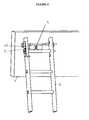
- This devicemakes it possible to anchor or hang in a non- permanent at least one safety device 2 which can be made up of scaffolding, as illustrated in Figure 5 or a scale as shown in Figure 6.
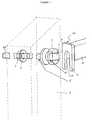
- This anchoring devicecomprises a part 3 for fixing to element 1 of construction, this fixing having to be generally performed permanently and an element 12 connecting the safety device 2 to the workpiece 3 fixing.
- the fixing or anchoring part 3such as a screw, a bolt or dowel, consists of an elongated body 5 provided at its end opposite to its end 5B of introduction into element 1 of construction of a generally protruding part called a bulge head 4. It also has between end 5B introduction and head 4 a limiting device the axial insertion of the body 5 of the attachment part 3 in building element 1.
- This organ represented in 9 in the figuresthus makes it possible to provide a space between construction element 1 and head 4 of part 3 of anchoring of the latter to allow cooperation of the various elements making up the anchoring device.
- the fixing part 3is generally constituted by a screw whose body 5 will therefore carry a part 5B threaded to facilitate attachment of the assembly by means of a plate and a nut, other modes of fixing the body 5 in the building element 1 can be considered.
- the body 5 axial insertion limitation member of the fixing part 3 in the building element 1can also affect a lot of shapes.
- this body of limitation of axial insertion of the body 5 of the part 3 of fixing in building element 1can be formed in one piece with the body 5 of piece 3 of fixation.
- this bodycan be constituted by example of at least one shoulder formed at the periphery of the body 5 of the part 3 for fixing between the head 4 and the end 5B for introducing the body 5 into the element 1 of construction.
- the member limiting the axial penetration of the body 5 of the part 3 of fixing in the building element 1can be consisting of an insert forming a spacer between construction element 1 and head 4 of part 3 of fixation.
- This patchsuch as a sleeve having at least one external peripheral shoulder or a grooved roller 9 is arranged to provide at least one continuous or discontinuous external circumferential groove between the head 4 of the fixing part 3 and the part 5A of the body 5 of the fixing part 3 intended to be introduced in element 1 of construction.
- the opening 13 profile of the connecting element 12is mounted astride in said groove 6 to surround at least partially the back of the throat 6.
- This insert, preferably grooved 6,is slidably introduced on the body 5 of the fixing part 3 to a stop position on the head 4 of the attachment part 3.
- the body 5protrudes from the construction 1 at its end opposite the screw head to allow its immobilization by means of a nut 7 cooperating with the threaded part 5b of the body 5.
- the groove 6is arranged at the screwed state of the fixing part 3, in element 1 of construction between the face of the construction intended for receive the safety device and the screw head 4.
- This groove 6is therefore perfectly visible in the screwed state of the fixing part 3 since it remains outside of construction 1. It should be noted that in all examples shown in the figures, the groove is provided at by means of an insert each time constituted by a grooved roller 9, this roller constituting the limitation of axial insertion of the body 5 of the part 3.
- This groove 6preferably has a shape section general trapezoid, the small base of the trapezoid constituting the bottom of the groove 6.
- the anchoring devicefurther includes a connecting element 12 intended to be attached to safety device 2.
- This connecting element 12allows you to anchor or hang, not permanently, the safety device 2 to the attachment part 3.
- this connecting element 12has at least one U-shaped opening 13 reversed.
- the connecting element 12is secured to the part 3 of fixing by a mounting with horse of the element 12 of connection on the body 5 of the fixing part 3, behind the head 4 of said part through the opening 13 which is fitted with the connecting element 12.
- This opening 13comes lodge in the space provided between head 4 and element 1 of construction thanks to the presence of the limiting device axial drive.
- the body 5has a groove 6 provided by means of an insert.
- the opening 13 of the connecting element 12is mounted astride in said throat.
- the groove 6, when it exists, presents a general trapezoidal section as has been described abovefacilitates the introduction of the edges 13A of the opening 13 of the element 12 in the groove 6 formed between the flanges of the grooved roller 9. Thanks to this positioning of the connecting element 12, all separation of the safety device 2 from the construction 1, when subjected to an effort of overturning, is prevented.
- connection between connecting element 12 and fixing part 3 in the direction of pivoting around of a substantially horizontal axisit can be in some cases necessary to immobilize in rotation the element link 12 relative to the fixing part 3.
- the insert and the head 4 of the attachment part 3have shapes additional nestable ensuring immobilization in rotation of the insert on the body 5 of said fixing part 3.
- the insertis a roller 9 with groove 6
- the flange 9A of the roller 9 opposite the head 4 of the part 3 of attachmenthas a groove 10 inside which comes to accommodate the head 4 of the fixing part 3 having a shape complementary to said groove 10.
- the head 4 of the part 3 of fixationaffects the shape of a square or rectangle.
- the fixing part 3further comprises at least two flats 11B, 11C, 11A substantially parallel formed respectively on the body 5 of the fixing part 7 and / or on the head 4 of the attachment part 3 and / or on the member for limiting the axial sinking of the body 5 of the fixing part 3 preferably consisting of a part added sliding to the body 5 of the fixing part 3 to a stop position on the head 4 of the attachment part 3.
- the head 4comprises at least two substantially parallel flats 11C
- these 11C flatsare arranged to cooperate with parts planes 16 of the connecting element 12 so as to ensure immobilization in rotation of the connecting element 12 when positioned on horseback behind the head 4 of the fixing part 3.
- the flats 11A, 11Bare as for arranged to cooperate with the 13A U-shaped edges of the opening 13 in U of the connecting element 12 and / or with planar portions 16 of the connecting element 12 so to ensure immobilization in rotation of the element 12 of connection when positioned astride throat 6 of the fixing part 3.
- the throat of the grooved roller 9has at least two adapted flats 11B to cooperate with the edges 13A used to delimit the branches of U of opening 13 in U of element 12 of link to ensure immobilization in rotation of the connecting element 12 in said groove.
- the head 4 of the part 3 fixingwhich is a rectangular head
- the flange 9A of the roller 9 with a groove opposite the head 4 of the part 3each have at least one periphery two parallel flats, these flats being respectively formed each by 11C by two parallel sides of the head 4 of attachment part 3, the others 11A by flaps cut from the flange 9A of the throat roller coming into abutment against the head 4 of the fixing part 3.
- These flats 11A, 11Care arranged to cooperate with flat parts 16 of the connecting piece 12 and ensure immobilization in rotation of the connecting element 12 during its positioning on horseback in groove 6 of part 3 of fixation.
- the connecting element 12can affect the shape of a tube 15, generally of section square, at least partially open on one of its faces, this tube being closed at one of its ends by a plate 14 comprising the opening 13 substantially in U shape.
- Plate 14 and tube 15cooperate with each other to allow, during overlapping mounting of the element 12 of connection on the fixing part 3, the overlap by the plate 14 of the body 5 of the attachment part 3 and the overlap by the straight side walls of the tube 15 of the head 4 of the attachment part 3.
- These walls sideare shown at 16 in Figure 4.
- the opening of one face of the tube 15 constituting the part 12 connecting over part of its length in the vicinity of the plate 14 carrying the opening 13makes it possible to spare the equivalent of a room as shown in this figure.
- Attachment piece 3is housed in the wall, usually after drilling a hole in the wall using a suitable tool. Attachment piece 3 is then introduced into the wall until eventually protrude from building element 1 and is maintained for example by means of a nut 7 screwed onto the body 5 of the attachment part 3. Attachment piece 3 is introduced in element 1 of construction in the state nested grooved roller 9 and head 4 of part 3 of fixing up to a position in which the roller 9 abuts on the face of the construction element 1 intended to receive the safety device 2.
- part 3is, thanks to its axial sinking limitation member, introduced in element 1 of construction so as to leave a space between head 4 of part 3 and face of construction element 1 intended to receive the security device.
- Flats, where they exist on this fixing part 3are then installed in a substantially vertical position.
- the fixing part 3is held in a position fixed, the nut 7 being movable relative to the body 5 of the fixing part 3. This makes it possible to maintain for sure correct orientation of the flats. This orientation of flats can be visually checked by looking at the position of the head 4 of the fixing part 3 when this has a rectangular shape.
- the connecting element 12is fixed to the device 2 of safety which must be anchored or attached to element 1 of construction.
- This safety device 2can for example be constituted by a scaffolding device of the type intended to simply come to bear on the construction. These scaffolding devices are well known to those versed in this art.
- An example of this device scaffoldingis shown in Figure 5.
- the arm affecting the shape of a tube 15 fitted to the element 12 of linkis generally fitted to the socket on the scaffolding structure.
- This connecting element 12can still be permanently installed on the structure scaffolding.
- the plate 14 carrying the opening 13 in U-shapedis arranged at the free end of this arm.
- the scaffolding structureis therefore high to come position above throat 6 or more generally body 5 of the attachment part 3 then lowered to bring the edges 13A opening 13 of the connecting element 12 in taken with groove 6 by an overlapping mounting in enclosing the bottom of the groove 6 with a variable clearance.
- the device securityconsists of a ladder which includes, at near one of its ends, a cross parallel to two uprights, this cross being equipped of a flap articulated on said crosspiece, this flap having at least one substantially shaped opening 13 of U which is mounted on horseback in a similar manner to that which been described above in the throat 6 of the body 5 or directly on the body 5 of the fixing part 3, the fixing part 3 which may be identical to what has been described above.
- an asset in rotation of the connecting element 12 on the part 3 of fixingis not essential. The goal is simply to prevent the ladder from overturning or sliding support on element 1 of construction.
- the U-shaped opening 13 of the connecting element 12is generally constituted by a notch formed on an edge of the connecting element 12, in this case a plate 14 of the latter.
Landscapes
- Engineering & Computer Science (AREA)
- Architecture (AREA)
- Mechanical Engineering (AREA)
- Structural Engineering (AREA)
- Civil Engineering (AREA)
- Ladders (AREA)
- Electrical Discharge Machining, Electrochemical Machining, And Combined Machining (AREA)
- Joining Of Building Structures In Genera (AREA)
- Soil Working Implements (AREA)
- Massaging Devices (AREA)
- Steering Control In Accordance With Driving Conditions (AREA)
- Ropes Or Cables (AREA)
- Transplanting Machines (AREA)
- Bipolar Transistors (AREA)
- Liquid Developers In Electrophotography (AREA)
- Emergency Lowering Means (AREA)
Abstract
Description
Translated fromFrenchLa présente invention concerne un dispositif d'ancrage ditpermanent dans un élément de construction, tel qu'un mur,pour ancrer ou accrocher de manière non permanente au moinsun dispositif de sécurité, tel qu'un échafaudage, unenacelle, une échelle, une plate-forme ou similaire.The present invention relates to a so-called anchoring devicepermanent in a building element, such as a wall,to anchor or hang non-permanently at leasta safety device, such as scaffolding,nacelle, ladder, platform or the like.
Un grand nombre de dispositifs d'ancrage du type précitéont été développés à ce jour. Ces dispositifs d'ancragecomprennent de manière générale une pièce de fixation àl'élément de construction et un élément de liaison entredispositif de sécurité et pièce de fixation. Cesdispositifs d'ancrage sont généralement constitués depièces de forme relativement complexe qui nécessitent enoutre une certaine dextérité de l'utilisateur pourpermettre un accrochage entre pièce de fixation et élémentde liaison. Du fait de la complexité des pièces, de telsdispositifs d'ancrage sont relativement onéreux. Lamultiplication de leur utilisation en raison de nouvellesnormes nécessite aujourd'hui de simplifier ces dispositifspour en réduire le coût et permettre leur implantation enun grand nombre d'endroits sur une construction.A large number of anchoring devices of the aforementioned typehave been developed to date. These anchoring devicesgenerally include a fastening part tothe building element and a connecting element betweensafety device and fixing part. Theseanchors generally consist ofrelatively complex shaped parts which requirebesides a certain dexterity of the user forallow attachment between fixing part and elementlink. Due to the complexity of the parts, suchanchors are relatively expensive. Themultiplication of their use due to newsstandards today require simplifying these devicesto reduce the cost and allow their establishment ina large number of places on a building.
On connaít également en particulier par FR A 2610027 desdispositifs non pas d'ancrage mais simplement de fixationconstitués d'une tige munie d'une tête. La tige traversantl'élément de construction est immobilisée dans l'élément deconstruction simplement au moyen d'une contre-plaquemaintenue par un écrou, cette immobilisation ne pouvantêtre effectuée qu'après insertion, dans l'espace séparantla tête de l'élément de construction, d'une équerre surlaquelle pourra être fixé le dispositif de sécurité àaccrocher. De ce fait, la manipulation du dispositif desécurité en vue de son accrochage ne peut pas s'opéreraisément à partir du sol car elle nécessite diversesopérations de vissage. En effet, la fixation du dispositifde sécurité à l'équerre avant immobilisation de l'équerresur la tige insérée dans l'élément de construction estimpossible du fait du mode de fixation de l'équerre à latige de fixation.We also know in particular from FR A 2610027not anchoring but simply fixing devicesconsisting of a rod fitted with a head. The rod crossingthe building element is immobilized in the element ofconstruction simply by means of a counterplateheld by a nut, this immobilization cannotonly after insertion, in the space separatingthe head of the building element, a square onwhich can be attached the safety device toto hook. Therefore, the manipulation of thesecurity for hanging cannot take placeeasily from the ground as it requires variousscrewing operations. Indeed, fixing the deviceof safety at the square before immobilizing the squareon the rod inserted in the building element isimpossible due to the method of fixing the bracket to thefixing rod.
Un but de la présente invention est donc de proposer undispositif d'ancrage dit permanent dont la conception,particulièrement simplifiée, permet de disposer d'undispositif d'ancrage de coût réduit.An object of the present invention is therefore to propose aso-called permanent anchoring device whose design,particularly simplified, allows to have alower cost anchoring device.
Un autre but de la présente invention est de proposer undispositif d'ancrage dont la conception permet une mise enplace aisée de l'élément de liaison sur la pièce defixation, cette mise en place pouvant s'effectuer à partirdu sol.Another object of the present invention is to provide aanchoring device whose design allowseasy placement of the connecting element on the workpieceattachment, this installation can be carried out fromof the ground.
A cet effet, l'invention a pour objet un dispositifd'ancrage dit permanent dans un élément, tel qu'un murd'une construction pour ancrer ou accrocher de manière nonpermanente au moins un dispositif de sécurité, tel qu'unéchafaudage, une nacelle, une échelle, une plate-forme ousimilaire, ce dispositif d'ancrage comprenant une pièce defixation permanente à l'élément de construction et unélément de liaison entre dispositif de sécurité et pièce defixation, cet élément de liaison comportant au moins une ouverture profilée en forme de U renversé, caractérisé ence que la pièce de fixation, telle que vis, boulon, brocheou cheville, est constituée d'un corps allongé munisuccessivement, depuis son extrémité d'introduction dansl'élément de construction, d'un organe de limitationd'enfoncement axial dans l'élément de construction et d'unetête de manière à ménager, derrière la tête de la pièce defixation, un espace permettant à l'élément de liaison fixéau dispositif de sécurité de pouvoir se positionner au-dessusde la pièce de fixation en vue d'une coopération aumoins avec la tête de ladite pièce de fixation, l'ouvertureprofilé de l'élément de liaison étant montée à cheval surle corps de la pièce de fixation derrière la tête de lapièce de fixation, de sorte que toute désolidarisation dudispositif de sécurité de l'élément de la construction,lorsqu'il est soumis à un effort de renversement, estempêché.To this end, the invention relates to a deviceanchor called permanent in an element, such as a wallof a construction for anchoring or hanging in a non-permanent at least one safety device, such as ascaffolding, a gondola, a ladder, a platform orsimilar, this anchoring device comprising a piece ofpermanent attachment to the building element and aconnecting element between safety device and workpiecefixing, this connecting element comprising at least oneshaped opening in the shape of an inverted U, characterized bywhat the fastener, such as screw, bolt, pinor ankle, consists of an elongated body providedsuccessively, from its insertion end inthe building element, a limiting memberaxial insertion into the building element and ahead so as to spare, behind the head of the workpieceattachment, a space allowing the attached connecting elementthe safety device to be able to position itself aboveof the fastener for cooperation withless with the head of said fastener, the openingprofile of the connecting element being mounted astridethe body of the fastener behind the head of thefixing piece, so that any separation of theconstruction element safety device,when subjected to an overturning force, isstop.
Grâce à la conception de la pièce de fixation, l'accrochageet le décrochage du dispositif de sécurité parl'intermédiaire de l'élément de liaison s'avèrent desopérations particulièrement aisées. Par ailleurs, laprésence de l'organe de limitation d'enfoncement axialpermet de sélectionner, au moment de l'ancrage,l'orientation angulaire souhaitée pour la tête de la piècede fixation.Thanks to the design of the fixing piece, the attachmentand the release of the safety device bythrough the connecting element prove to beparticularly easy operations. In addition, thepresence of the axial drive-in limitation memberallows you to select, when anchoring,desired angular orientation for the head of the partof fixation.
Selon une forme de réalisation préférée de l'invention,l'organe de limitation d'enfoncement axial du corps de lapièce de fixation dans l'élément de construction estconstitué d'une pièce rapportée sur le corps et formantentretoise entre l'élément de construction et la tête de lapièce de fixation.According to a preferred embodiment of the invention,the axial insertion limitation member of the body of thefastener in the building element isconsisting of a part attached to the body and formingspacer between the building element and the head of thefixing piece.
La conception d'un organe de limitation d'enfoncement sousforme d'une pièce rapportée permet l'utilisation d'une tiged'ancrage classique. Par ailleurs, une coopération de cetorgane avec la tête de la pièce de fixation est facilitée notamment en vue d'une immobilisation en rotation de cetorgane sur le corps de la pièce de fixation.The design of a sinking limitation device undershape of an insert allows the use of a rodclassic anchor. Furthermore, cooperation from thisbody with the head of the fixing piece is facilitatedin particular with a view to immobilizing in rotation thisbody on the body of the fastener.
L'invention sera bien comprise à la lecture de ladescription suivante d'exemples de réalisation, enréférence aux dessins annexés dans lesquels :
Le dispositif d'ancrage, objet de l'invention, est undispositif d'ancrage dit permanent dans la mesure où il estdestiné normalement, en ce qui concerne au moins une partie des éléments constitutifs de ce dispositif, à être laisséde manière permanente dans l'élément de la construction telqu'un mur.The anchoring device, object of the invention, is aanchoring device said to be permanent insofar as it isnormally intended, with respect to at least someof the components of this device, to be leftpermanently in the building element suchthan a wall.
Ce dispositif permet d'ancrer ou d'accrocher de manière nonpermanente au moins un dispositif 2 de sécurité qui peutêtre constitué par un échafaudage, comme l'illustre lafigure 5 ou une échelle comme l'illustre la figure 6.This device makes it possible to anchor or hang in a non-permanent at least one
Ce dispositif d'ancrage comprend une pièce 3 de fixation àl'élément 1 de construction, cette fixation devant êtreréalisée de manière généralement permanente et un élément12 de liaison entre le dispositif 2 de sécurité et la pièce3 de fixation.This anchoring device comprises a
La pièce 3 de fixation ou d'ancrage, telle qu'une vis, unboulon ou une cheville, est constituée d'un corps 5 allongépourvu à son extrémité opposée à son extrémité 5Bd'introduction dans l'élément 1 de construction d'unepartie généralement saillante formant un renflement appeléetête 4. Il comporte encore entre extrémité 5Bd'introduction et tête 4 un organe de limitation del'enfoncement axial du corps 5 de la pièce 3 de fixationdans l'élément 1 de construction. Cet organe représenté en9 aux figures, permet ainsi de ménager un espace entreélément 1 de construction et tête 4 de la pièce 3 defixation à l'état ancré de cette dernière pour permettreune coopération des différents éléments constituant ledispositif d'ancrage.The fixing or anchoring
Bien que la pièce 3 de fixation soit généralementconstituée par une vis dont le corps 5 portera donc unepartie 5B filetée pour faciliter la fixation de l'ensembleau moyen d'une plaque et d'un écrou, d'autres modes defixation du corps 5 dans l'élément 1 de constructionpeuvent être envisagés.Although the
L'organe de limitation d'enfoncement axial du corps 5 de la pièce 3 de fixation dans l'élément 1 de construction peutégalement affecter un grand nombre de formes. Dans unpremier mode de réalisation non-représenté, cet organe delimitation d'enfoncement axial du corps 5 de la pièce 3 defixation dans l'élément 1 de construction peut être forméd'une seule pièce avec le corps 5 de la pièce 3 defixation. Dans ce cas, cet organe peut être constitué parexemple d'au moins un épaulement ménagé à la périphérie ducorps 5 de la pièce 3 de fixation entre la tête 4 etl'extrémité 5B d'introduction du corps 5 dans l'élément 1de construction.The
Dans un autre mode de réalisation de l'invention, l'organede limitation d'enfoncement axial du corps 5 de la pièce 3de fixation dans l'élément 1 de construction peut êtreconstitué d'une pièce rapportée formant entretoise entrel'élément 1 de construction et la tête 4 de la pièce 3 defixation. Cette pièce rapportée tel qu'un manchonprésentant au moins un épaulement périphérique externe ouun galet 9 à gorge est agencée pour ménager au moins unegorge circonférentielle externe continue ou discontinueentre la tête 4 de la pièce 3 de fixation et la partie 5Adu corps 5 de la pièce 3 de fixation destinée à êtreintroduite dans l'élément 1 de construction. L'ouverture 13profilée de l'élément 12 de liaison est montée à chevaldans la dite gorge 6 pour entourer au moins partiellementle fond de la gorge 6. Cette pièce rapportée, de préférenceà gorge 6, est introduite à coulissement sur le corps 5 dela pièce 3 de fixation jusqu'à une position en butée sur latête 4 de la pièce 3 de fixation.In another embodiment of the invention, the memberlimiting the axial penetration of the
Généralement, le corps 5 fait saillie de la construction 1à son extrémité opposée à la tête de vis pour permettre sonimmobilisation au moyen d'un écrou 7 coopérant avec lapartie filetée 5b du corps 5. La gorge 6 est disposée, àl'état vissé de la pièce 3 de fixation, dans l'élément 1 deconstruction entre la face de la construction destinée àrecevoir le dispositif de sécurité et la tête 4 de vis.Generally, the
Cette gorge 6 est donc parfaitement visible à l'état visséde la pièce 3 de fixation puisqu'elle demeure à l'extérieurde la construction 1. Il est à noter que dans tous lesexemples représentés aux figures, la gorge est ménagée aumoyen d'une pièce rapportée constituée à chaque fois par ungalet 9 à gorge, ce galet constituant l'organe delimitation d'enfoncement axial du corps 5 de la pièce 3.This
Cette gorge 6 présente de préférence une section d'alluregénérale trapézoïdale, la petite base du trapèzeconstituant le fond de la gorge 6.This
Outre cette pièce 3 de fixation, le dispositif d'ancragecomporte encore un élément 12 de liaison destiné à êtrefixé au dispositif 2 de sécurité. Cet élément 12 de liaisonpermet d'ancrer ou d'accrocher, de manière non permanente,le dispositif 2 de sécurité à la pièce 3 de fixation. Pourpermettre cette fixation, cet élément 12 de liaisoncomporte au moins une ouverture 13 profilée en forme de Urenversé. L'élément 12 de liaison est solidarisé à la pièce3 de fixation par un montage à cheval de l'élément 12 deliaison sur le corps 5 de la pièce 3 de fixation, derrièrela tête 4 de ladite pièce grâce à l'ouverture 13 dont estmuni l'élément 12 de liaison. Cet ouverture 13 vient seloger dans l'espace ménagé entre tête 4 et élément 1 deconstruction grâce à la présence de l'organe de limitationd'enfoncement axial. Dans le cas où le corps 5 comporte unegorge 6 ménagée au moyen d'une pièce rapportée. L'ouverture13 de l'élément 12 de liaison est montée à cheval dansladite gorge. Ce montage à cheval est obtenu enpositionnant l'élément 12 de liaison au-dessus de la pièce3 de fixation puis abaissement de ce dernier de telle sorteque les bords 13A de l'ouverture 13 ménagée dans l'élémentde liaison 12 viennent enserrer avec plus ou moins de jeu,le fond de la gorge 6 de la pièce 3 de fixation ousimplement le corps 5 de la pièce 3 en l'absence de gorge6. Il en résulte un positionnement particulièrement simplede l'élément 12 de liaison sur la pièce 3 de fixation.In addition to this
Le fait que la gorge 6, lorsqu'elle existe, présente unesection d'allure générale trapézoïdale comme cela a étédécrit ci-dessus facilite l'introduction des bords 13A del'ouverture 13 de l'élément 12 dans la gorge 6 ménagéeentre les flasques du galet 9 à gorge. Grâce à cepositionnement de l'élément 12 de liaison, toutedésolidarisation du dispositif 2 de sécurité de laconstruction 1, lorsqu'il est soumis à un effort derenversement, est empêchée.The fact that the
Outre cette solidarisation entre élément 12 de liaison etpièce 3 de fixation dans le sens d'un pivotement autourd'un axe sensiblement horizontal, il peut être danscertains cas nécessaire d'immobiliser en rotation l'élémentde liaison 12 par rapport à la pièce 3 de fixation. Pourpermettre cette immobilisation, dans le cas où la gorge 6est ménagée dans une pièce rapportée, la pièce rapportée etla tête 4 de la pièce 3 de fixation comportent des formescomplémentaires emboítables assurant une immobilisation enrotation de la pièce rapportée sur le corps 5 de laditepièce 3 de fixation. Ainsi, dans les exemples représentésoù la pièce rapportée est un galet 9 à gorge 6, le flasque9A du galet 9 en regard de la tête 4 de la pièce 3 defixation comporte une rainure 10 à l'intérieur de laquellevient se loger la tête 4 de la pièce 3 de fixationprésentant une forme complémentaire à ladite rainure 10.Dans les exemples représentés, la tête 4 de la pièce 3 defixation affecte la forme d'un carré ou d'un rectangle.In addition to this connection between connecting
La pièce 3 de fixation comporte en outre au moins deuxméplats 11B, 11C, 11A sensiblement parallèles ménagésrespectivement sur le corps 5 de la pièce 7 de fixationet/ou sur la tête 4 de la pièce 3 de fixation et/ou surl'organe de limitation d'enfoncement axial du corps 5 de lapièce 3 de fixation constitué de préférence d'une piècerapportée introduite à coulissement sur le corps 5 de lapièce 3 de fixation jusqu'à une position en butée sur la tête 4 de la pièce 3 de fixation. Dans le cas où la tête 4comporte au moins deux méplats 11C sensiblement parallèles,ces méplats 11C sont agencés pour coopérer avec des partiesplanes 16 de l'élément 12 de liaison de manière à assurerune immobilisation en rotation de l'élément 12 de liaisonlors de son positionnement à cheval derrière la tête 4 dela pièce 3 de fixation. Les méplats 11A, 11B sont quant àeux agencés pour coopérer avec les bords 13A en U del'ouverture 13 en U de l'élément 12 de liaison et/ou avecdes parties planes 16 de l'élément 12 de liaison de manièreà assurer une immobilisation en rotation de l'élément 12 deliaison lors de son positionnement à cheval dans la gorge 6de la pièce 3 de fixation.The fixing
Ainsi, dans l'exemple représenté à la figure 3, la gorge dugalet 9 à gorge comporte au moins deux méplats 11B adaptésà coopérer avec les bords 13A servant à la délimitation desbranches du U de l'ouverture 13 en U de l'élément 12 deliaison pour assurer une immobilisation en rotation del'élément 12 de liaison dans ladite gorge.Thus, in the example shown in Figure 3, the throat of the
Dans le cas du mode de réalisation de la pièce 3 defixation représenté à la figure 2, la tête 4 de la pièce 3de fixation, qui est une tête rectangulaire, et le flasque9A du galet 9 à gorge en regard de la tête 4 de la pièce 3de fixation comportent chacun à leur périphérie au moinsdeux méplats parallèles, ces méplats étant respectivementconstitués les uns 11C par deux côtés parallèles de la tête4 de la pièce 3 de fixation, les autres 11A par des panscoupés du flasque 9A du galet à gorge venant en butéecontre la tête 4 de la pièce 3 de fixation. Ces méplats11A, 11C sont agencés pour coopérer avec des parties planes16 de la pièce 12 de liaison et assurer une immobilisationen rotation de l'élément 12 de liaison lors de sonpositionnement à cheval dans la gorge 6 de la pièce 3 defixation. Dans ce second cas, l'élément 12 de liaison peutaffecter la forme d'un tube 15, généralement de sectioncarrée, ouvert au moins partiellement sur l'une de ses faces, ce tube étant fermé à l'une de ses extrémités parune platine 14 comportant l'ouverture 13 sensiblement enforme de U. Platine 14 et tube 15 coopèrent entre eux pourpermettre, lors du montage à chevauchement de l'élément 12de liaison sur la pièce 3 de fixation, le chevauchement parla platine 14 du corps 5 de la pièce 3 de fixation et lechevauchement par les parois latérales rectilignes du tube15 de la tête 4 de la pièce 3 de fixation. Ces paroislatérales sont représentées en 16 à la figure 4.L'ouverture d'une face du tube 15 constitutif de la pièce12 de liaison sur une partie de sa longueur au voisinage dela platine 14 portant l'ouverture 13 permet de ménagerl'équivalent d'une chambre comme le montre cette figure.In the case of the embodiment of
En pratique, l'utilisation du dispositif d'ancrage décritci-dessus est la suivante. La pièce 3 de fixation est logéedans le mur, généralement après perçage d'un trou dans lemur au moyen d'un outil approprié. La pièce 3 de fixationest alors introduite dans le mur jusqu'à éventuellementfaire saillie de l'élément 1 de construction et estmaintenue par exemple au moyen d'un écrou 7 vissé sur lecorps 5 de la pièce 3 de fixation. La pièce 3 de fixationest introduite dans l'élément 1 de construction à l'étatemboíté du galet 9 à gorge et de la tête 4 de la pièce 3 defixation jusqu'à une position dans laquelle le galet 9vient en butée sur la face de l'élément 1 de constructiondestinée à recevoir le dispositif 2 de sécurité. Enl'absence de pièce rapportée sur le corps, la pièce 3 est,grâce à son organe de limitation d'enfoncement axial,introduite dans l'élément 1 de construction de manière àménager un espace entre tête 4 de la pièce 3 et face del'élément 1 de construction destinée à recevoir ledispositif de sécurité. Les méplats, lorsqu'ils existentsur cette pièce 3 de fixation, sont alors installés dansune position sensiblement verticale. Au cours du vissage,la pièce 3 de fixation est maintenue dans une positionfixe, l'écrou 7 étant mobile par rapport au corps 5 de lapièce 3 de fixation. Ceci permet de maintenir à coup sûr une orientation correcte des méplats. Cette orientation desméplats peut être vérifiée visuellement en regardant laposition de la tête 4 de la pièce 3 de fixation lorsquecelle-ci affecte une forme rectangulaire. Parallèlement,l'élément 12 de liaison est fixé au dispositif 2 desécurité qui doit être ancré ou accroché à l'élément 1 deconstruction. Ce dispositif 2 de sécurité peut par exempleêtre constitué par un dispositif d'échafaudage du typedestiné à venir simplement en appui sur la construction.Ces dispositifs d'échafaudage sont bien connus à ceuxversés dans cet art. Un exemple de ce dispositifd'échafaudage est représenté à la figure 5. Le brasaffectant la forme d'un tube 15 équipant l'élément 12 deliaison est généralement monté à emboítement sur lastructure d'échafaudage. Cet élément 12 de liaison peutencore être installé de manière permanente sur la structured'échafaudage. La platine 14 portant l'ouverture 13 enforme de U est disposée à l'extrémité libre de ce bras. Lastructure d'échafaudage est donc élevée pour venir sepositionner au-dessus de la gorge 6 ou plus généralement ducorps 5 de la pièce 3 de fixation puis abaissée pour amenerles bords 13A l'ouverture 13 de l'élément 12 de liaison enprise avec la gorge 6 par un montage à chevauchement enenserrant le fond de la gorge 6 avec un jeu variable.In practice, the use of the anchoring device describedabove is as follows.
Dans l'exemple représenté à la figure 6, le dispositif desécurité est constitué par une échelle qui comporte, auvoisinage de l'une de ses extrémités, une traverseparallèle à deux montants, cette traverse étant équipéed'un volet articulé sur ladite traverse, ce voletcomportant au moins une ouverture 13 sensiblement en formede U qui est montée à cheval de manière analogue à ce qui aété décrit ci-dessus dans la gorge 6 du corps 5 oudirectement sur le corps 5 de la pièce 3 de fixation, lapièce 3 de fixation pouvant être identique à ce qui a étédécrit ci-dessus. Dans ce cas, une immobilisation enrotation de l'élément 12 de liaison sur la pièce 3 defixation n'est pas indispensable. Le but est simplement d'éviter un renversement ou un glissement de l'échelle enappui sur l'élément 1 de construction.In the example shown in Figure 6, the devicesecurity consists of a ladder which includes, atnear one of its ends, a crossparallel to two uprights, this cross being equippedof a flap articulated on said crosspiece, this flaphaving at least one substantially shaped opening 13of U which is mounted on horseback in a similar manner to that whichbeen described above in the
Il est à noter que, dans tous les exemples précités,l'ouverture 13 en forme de U de l'élément 12 de liaison estgénéralement constituée par une encoche ménagée sur un bordde l'élément 12 de liaison, en l'occurrence une platine 14de cette dernière.Note that in all of the above examples,the
Par ailleurs, pour faciliter la tenue mécanique del'ensemble, il peut être prévu, sur le flasque du galet 9 àgorge en appui sur l'élément 1 de construction, des griffes17 destinées à s'enfoncer dans la construction au cours duserrage.Furthermore, to facilitate the mechanical strength ofthe assembly, it can be provided, on the flange of the
Claims (13)
Translated fromFrenchcaractérisé en ce que la pièce (3) de fixation, telle quevis, boulon, broche ou cheville, est constituée d'un corps(5) allongé muni successivement, depuis son extrémité (5B)d'introduction dans l'élément (1) de construction, d'unorgane (9) de limitation d'enfoncement axial dans l'élément(1) de construction et d'une tête (4) de manière à ménager,derrière la tête (4) de la pièce (3) de fixation, un espacepermettant à l'élément (12) de liaison fixé au dispositif(2) de sécurité de pouvoir se positionner au-dessus de lapièce (3) de fixation en vue d'une coopération au moinsavec la tête (4) de ladite pièce (3) de fixation,l'ouverture (13) profilé de l'élément (12) de liaison étantmontée à cheval sur le corps (5) de la pièce (3) defixation derrière la tête (4) de la pièce (3) de fixation,de sorte que toute désolidarisation du dispositif (2) desécurité de l'élément (1) de la construction, lorsqu'il estsoumis à un effort de renversement, est empêché.So-called permanent anchoring device in an element (1), such as a building wall for anchoring or hanging in a non-permanent manner at least one safety device (2), such as a scaffolding, a nacelle, ladder, platform or the like, this anchoring device comprising a part (3) for permanent attachment to the construction element (1) and a connecting element (12) between safety device (2) and part ( 3) for fixing, this connecting element (12) comprising at least one opening (13) profiled in the shape of an inverted U,
characterized in that the fixing part (3), such as a screw, bolt, pin or dowel, consists of an elongated body (5) successively provided, from its end (5B) for introduction into the element (1 ) of construction, of a member (9) for limiting axial penetration into the element (1) of construction and of a head (4) so as to provide, behind the head (4) of the part (3 ) for fixing, a space allowing the connecting element (12) fixed to the safety device (2) to be able to be positioned above the fixing part (3) with a view to cooperation at least with the head (4) of said fixing part (3), the profiled opening (13) of the connecting element (12) being mounted astride the body (5) of the fixing part (3) behind the head ( 4) of the fixing part (3), so that any separation of the safety device (2) from the element (1) of the construction, when it is subjected to an overturning force , is prevented.
caractérisé en ce que l'organe de limitation d'enfoncementaxial du corps (5) de la pièce (3) de fixation dansl'élément (1) de construction est constitué d'au moins unépaulement ménagé à la périphérie du corps (5) de la pièce(3) de fixation entre la tête (4) et l'extrémité (5B) d'introduction du corps (5) de la pièce (3) de fixationdans l'élément (1) de constructionAnchoring device according to claim 1,
characterized in that the member for limiting the axial insertion of the body (5) of the part (3) for fixing in the construction element (1) consists of at least one shoulder formed at the periphery of the body ( 5) of the part (3) for fixing between the head (4) and the end (5B) of introduction of the body (5) of the part (3) for fixing in the element (1) of construction
caractérisé en ce que l'organe de limitation d'enfoncementaxial du corps (5) de la pièce (3) de fixation dansl'élément (1) de construction est constitué d'une piècerapportée sur le corps (5) et formant entretoise entrel'élément (1) de construction et la tête (4) de la pièce(3) de fixation.Anchoring device according to claim 1,
characterized in that the member for limiting the axial insertion of the body (5) of the part (3) for fixing in the construction element (1) consists of a part attached to the body (5) and forming spacer between the construction element (1) and the head (4) of the fixing part (3).
caractérisé en ce que la pièce rapportée, telle qu'unmanchon présentant au moins un épaulement périphériqueexterne ou un galet (9) à gorge est agencée pour ménager aumoins une gorge (6) circonférentielle externe continue oudiscontinue disposée entre la tête (4) de la pièce (3) defixation et la partie (5A) du corps (5) de la pièce (3) defixation destiné à être introduite dans l'élément (1) deconstruction, l'ouverture (13) profilée de l'élément (12)de liaison étant montée à cheval dans la dite gorge (6)pour entourer au moins partiellement le fond de la ditegorge (6).Anchoring device according to claim 3,
characterized in that the insert, such as a sleeve having at least one external peripheral shoulder or a grooved roller (9), is arranged to provide at least one continuous or discontinuous external circumferential groove (6) disposed between the head (4 ) of the fixing part (3) and the part (5A) of the body (5) of the fixing part (3) intended to be introduced into the construction element (1), the profiled opening (13) of the connecting element (12) being mounted astride said groove (6) to at least partially surround the bottom of said groove (6).
caractérisé en ce que la pièce rapportée, de préférence àgorge, est introduite à coulissement sur le corps (5) de lapièce (3) de fixation jusqu'à une position en butée sur latête (4) de la pièce (3) de fixation.Anchoring device according to one of claims 3 and 4,
characterized in that the insert, preferably grooved, is slidably introduced on the body (5) of the fixing part (3) to a position in abutment on the head (4) of the part (3) of fixation.
caractérisé en ce que la gorge (6) présente une sectiond'allure générale trapézoïdale, la petite base du trapèzeconstituant le fond de la gorge (6).Anchoring device according to claim 4,
characterized in that the groove (6) has a generally trapezoidal section, the small base of the trapezoid constituting the bottom of the groove (6).
caractérisé en ce que la pièce rapportée et la tête (4) dela pièce (3) de fixation comportent des formescomplémentaires emboítables assurant une immobilisation enrotation de la pièce rapportée sur le corps (5) de laditepièce (3) de fixation.Anchoring device according to one of claims 3 to 6,
characterized in that the insert and the head (4) of the attachment part (3) comprise complementary nestable forms ensuring immobilization in rotation of the insert on the body (5) of said attachment part (3).
caractérisé en ce que la pièce rapportée est un galet (9) àgorge, le flasque (9A) du galet (9) en regard de la tête(4) de la pièce (3) de fixation comportant une rainure (10)à l'intérieur de laquelle vient se loger la tête (4) de lapièce (3) de fixation présentant une forme complémentaire àladite rainure (10).Anchoring device according to one of claims 3 to 7,
characterized in that the insert is a grooved roller (9), the flange (9A) of the roller (9) facing the head (4) of the fixing part (3) comprising a groove (10) at the 'interior of which is housed the head (4) of the part (3) for fixing having a shape complementary to said groove (10).
caractérisé en ce que la tête (4) de la pièce (3) defixation comporte au moins deux méplats (11C) sensiblementparallèles, ces méplats (11C) étant agencés pour coopéreravec des parties planes (16) de l'élément (12) de liaisonde manière à assurer une immobilisation en rotation del'élément (12) de liaison lors de son positionnement àcheval derrière la tête (4) de la pièce (3) de fixation.Anchoring device according to one of claims 1 to 8,
characterized in that the head (4) of the fixing part (3) has at least two substantially parallel flats (11C), these flats (11C) being arranged to cooperate with flat parts (16) of the element (12 ) connecting so as to ensure immobilization in rotation of the connecting element (12) when it is positioned astride the head (4) of the fixing part (3).
caractêrisé en ce que la pièce (3) de fixation comporte aumoins deux méplats (11A, 11B, 11C) sensiblement parallèlesménagés sur le corps (5) de la pièce (3) de fixation et/ousur la tête (4) de la pièce (3) de fixation et/ou surl'organe de limitation d'enfoncement axial du corps (5) dela pièce (3) de fixation constitué de préférence d'unepièce rapportée introduite à coulissement sur le corps (5)de la pièce (3) de fixation jusqu'à une position en butéesur la tête (4) de la pièce (3) de fixation, lesditsméplats étant agencés pour coopérer avec les bords (13A) enU de l'ouverture (13) en U de l'élément (12) de liaison et/ou avec des parties planes (16) de l'élément (12) deliaison de manière à assurer une immobilisation en rotationde l'élément (12) de liaison lors de son positionnement àcheval derrière la tête (4) de la pièce (3) de fixation.Anchoring device according to one of claims 1 to 9,
characterized in that the fixing piece (3) comprises at least two flats (11A, 11B, 11C) substantially parallel formed on the body (5) of the fixing piece (3) and / or on the head (4) of the part (3) for fixing and / or on the member for limiting the axial sinking of the body (5) of the part (3) for fixing preferably consisting of an insert inserted slidingly on the body (5) of the fixing piece (3) to a position in abutment on the head (4) of the fixing piece (3), said flats being arranged to cooperate with the U-shaped edges (13A) of the opening (13 ) in U of the connecting element (12) and / or with planar parts (16) of the connecting element (12) so as to immobilize in rotation the connecting element (12) during its positioning astride the head (4) of the fixing part (3).
caractérisé en ce que les méplats sont ménagés d'une partdans le flasque (9A) d'un galet (9) à gorge, monté àcoulissement sur le corps (5) de la pièce (3) de fixationet venant en butée contre la tête (4) de la pièce (3) defixation, d'autre part sur la tête (4) de la pièce (3) defixation.Anchoring device according to claim 10,
characterized in that the flats are formed on the one hand in the flange (9A) of a roller (9) grooved, mounted to slide on the body (5) of the piece (3) of fixing and coming into abutment against the head (4) of the fixing piece (3), on the other hand on the head (4) of the fixing piece (3).
caractérisé en ce que l'ouverture (13) en forme de U del'élément (12) de liaison est constituée par une encocheménagée sur un bord dudit élément (12) de liaison.Anchoring device according to one of claims 1 to 11,
characterized in that the U-shaped opening (13) of the connecting element (12) consists of a notch formed on an edge of said connecting element (12).
caractérisé en ce que l'élément (12) de liaison affecte laforme d'un tube (15), ouvert au moins partiellement surl'une de ses faces et fermé à l'une de ses extrémités parune platine (14) comportant l'ouverture (13) sensiblementen forme de U, platine (14) et tube (15) coopérant entreeux pour permettre, lors du montage à chevauchement del'élément (12) de liaison sur la pièce (3) de fixation, lechevauchement par la platine (14) du corps (5) de la pièce(3) de fixation et le chevauchement par les parois (16)latérales rectilignes du tube (15) de la tête (4) de lapièce (3) de fixation.Anchoring device according to one of claims 1 to 12,
characterized in that the connecting element (12) takes the form of a tube (15), open at least partially on one of its faces and closed at one of its ends by a plate (14) comprising the opening (13) substantially U-shaped, plate (14) and tube (15) cooperating with each other to allow, during the overlapping mounting of the connecting element (12) on the fixing part (3), the overlap by the plate (14) of the body (5) of the fixing piece (3) and the overlapping by the rectilinear lateral walls (16) of the tube (15) of the head (4) of the piece (3) of fixation.
Applications Claiming Priority (4)
| Application Number | Priority Date | Filing Date | Title |
|---|---|---|---|
| FR9911952AFR2798958B1 (en) | 1999-09-24 | 1999-09-24 | SECURITY DEVICE |
| FR9911951 | 1999-09-24 | ||
| FR9911952 | 1999-09-24 | ||
| FR9911951AFR2799805B1 (en) | 1999-09-24 | 1999-09-24 | PERMANENT ANCHORING DEVICE |
Publications (2)
| Publication Number | Publication Date |
|---|---|
| EP1087075A1true EP1087075A1 (en) | 2001-03-28 |
| EP1087075B1 EP1087075B1 (en) | 2004-05-26 |
Family
ID=26235115
Family Applications (2)
| Application Number | Title | Priority Date | Filing Date |
|---|---|---|---|
| EP00402634AExpired - LifetimeEP1087075B1 (en) | 1999-09-24 | 2000-09-22 | Permanent anchoring device |
| EP00402635AExpired - LifetimeEP1087098B1 (en) | 1999-09-24 | 2000-09-22 | Safety device |
Family Applications After (1)
| Application Number | Title | Priority Date | Filing Date |
|---|---|---|---|
| EP00402635AExpired - LifetimeEP1087098B1 (en) | 1999-09-24 | 2000-09-22 | Safety device |
Country Status (6)
| Country | Link |
|---|---|
| EP (2) | EP1087075B1 (en) |
| AT (2) | ATE267932T1 (en) |
| DE (2) | DE60011003T2 (en) |
| DK (2) | DK1087075T3 (en) |
| ES (2) | ES2220362T3 (en) |
| PT (2) | PT1087075E (en) |
Cited By (2)
| Publication number | Priority date | Publication date | Assignee | Title |
|---|---|---|---|---|
| US20160169192A1 (en)* | 2014-12-15 | 2016-06-16 | Acciona Windpower, S.A. | Wind Turbine with a Concrete Tower and Method for the Assembly Thereof |
| CN112227700A (en)* | 2020-10-13 | 2021-01-15 | 麦田建设有限公司 | Temporary scaffold mounting device for shear wall in constructional engineering |
Families Citing this family (13)
| Publication number | Priority date | Publication date | Assignee | Title |
|---|---|---|---|---|
| NO20022504L (en)* | 2002-05-28 | 2003-12-01 | Terje H Houen | A ladder securing device for securing the ladder in an inclined upright position |
| US7066299B1 (en) | 2004-04-08 | 2006-06-27 | Jeffrey John Fleming | Portable ladder suspension apparatus or a portable ladder for suspension or the combination thereof |
| US7950497B2 (en) | 2004-07-29 | 2011-05-31 | Surrey Hills Hire Pty. Ltd. | Ladder stabilising device |
| GB0523425D0 (en)* | 2005-11-17 | 2005-12-28 | Forest Safety Products Ltd | A ladder safety device |
| CN101469599B (en)* | 2007-12-28 | 2011-12-07 | 安徽省电力公司蚌埠供电公司 | Insulating combined ladder and combined erecting method thereof |
| GB0907949D0 (en)* | 2009-05-08 | 2009-06-24 | Arnold Stuart | Fall restraint system and access ladder |
| CN105201400B (en)* | 2015-09-15 | 2017-03-22 | 国网北京市电力公司 | Fixing device |
| CA2936214A1 (en)* | 2016-07-14 | 2018-01-14 | Richard Milton | Ladder safety device |
| FR3054592B1 (en)* | 2016-08-01 | 2020-09-18 | 4Nrj | DEVICE FOR MAINTAINING A LADDER IN A USED POSITION TO SAFEGUARD A WORK AT HEIGHT |
| FR3092131B1 (en)* | 2019-01-25 | 2022-06-24 | Sade Cie Generale De Travaux Dhydraulique | Holding device configured to hold a ladder against a surface |
| CN110439244A (en)* | 2019-08-12 | 2019-11-12 | 中国建筑第二工程局有限公司 | Scaffold for building |
| CN112211390A (en)* | 2020-09-28 | 2021-01-12 | 安徽长青建筑制品有限公司 | Outer wall connection structure for building construction scaffold |
| CN117703249A (en)* | 2023-10-31 | 2024-03-15 | 云南电网有限责任公司输电分公司 | A self-supporting combination telescopic insulated ladder |
Citations (3)
| Publication number | Priority date | Publication date | Assignee | Title |
|---|---|---|---|---|
| FR2547632A1 (en)* | 1983-06-15 | 1984-12-21 | Moreau Pierre | Anchoring device |
| FR2610027A1 (en)* | 1987-01-26 | 1988-07-29 | Ricouard Marcel | Folding and height-adjustable bracket for supporting overhanging platforms |
| EP0839975A1 (en)* | 1996-10-30 | 1998-05-06 | Dimos, Société Anonyme | Anchor arrangement |
Family Cites Families (3)
| Publication number | Priority date | Publication date | Assignee | Title |
|---|---|---|---|---|
| FR1292592A (en)* | 1961-06-17 | 1962-05-04 | Tubesca Anciens Etablissements | Hook in particular for ladders or other applications and ladders provided with this hook or similar hook |
| US4823912A (en)* | 1988-06-06 | 1989-04-25 | Gould William E | Multipurpose ladder fixture |
| DE9013505U1 (en)* | 1990-09-26 | 1992-01-30 | Towet, Manfred | Safety element for securing a ladder leaning against a fixed gutter or similar |
- 2000
- 2000-09-22ESES00402635Tpatent/ES2220362T3/ennot_activeExpired - Lifetime
- 2000-09-22DEDE60011003Tpatent/DE60011003T2/ennot_activeExpired - Fee Related
- 2000-09-22ESES00402634Tpatent/ES2220361T3/ennot_activeExpired - Lifetime
- 2000-09-22PTPT00402634Tpatent/PT1087075E/enunknown
- 2000-09-22PTPT00402635Tpatent/PT1087098E/enunknown
- 2000-09-22DEDE60011358Tpatent/DE60011358T2/ennot_activeExpired - Fee Related
- 2000-09-22ATAT00402634Tpatent/ATE267932T1/ennot_activeIP Right Cessation
- 2000-09-22DKDK00402634Tpatent/DK1087075T3/enactive
- 2000-09-22ATAT00402635Tpatent/ATE268861T1/ennot_activeIP Right Cessation
- 2000-09-22DKDK00402635Tpatent/DK1087098T3/enactive
- 2000-09-22EPEP00402634Apatent/EP1087075B1/ennot_activeExpired - Lifetime
- 2000-09-22EPEP00402635Apatent/EP1087098B1/ennot_activeExpired - Lifetime
Patent Citations (3)
| Publication number | Priority date | Publication date | Assignee | Title |
|---|---|---|---|---|
| FR2547632A1 (en)* | 1983-06-15 | 1984-12-21 | Moreau Pierre | Anchoring device |
| FR2610027A1 (en)* | 1987-01-26 | 1988-07-29 | Ricouard Marcel | Folding and height-adjustable bracket for supporting overhanging platforms |
| EP0839975A1 (en)* | 1996-10-30 | 1998-05-06 | Dimos, Société Anonyme | Anchor arrangement |
Cited By (3)
| Publication number | Priority date | Publication date | Assignee | Title |
|---|---|---|---|---|
| US20160169192A1 (en)* | 2014-12-15 | 2016-06-16 | Acciona Windpower, S.A. | Wind Turbine with a Concrete Tower and Method for the Assembly Thereof |
| US10100525B2 (en)* | 2014-12-15 | 2018-10-16 | Acciona Windpower, S.A. | Wind turbine with a concrete tower and method for the assembly thereof |
| CN112227700A (en)* | 2020-10-13 | 2021-01-15 | 麦田建设有限公司 | Temporary scaffold mounting device for shear wall in constructional engineering |
Also Published As
| Publication number | Publication date |
|---|---|
| ATE268861T1 (en) | 2004-06-15 |
| DE60011358T2 (en) | 2005-08-25 |
| DE60011003D1 (en) | 2004-07-01 |
| ATE267932T1 (en) | 2004-06-15 |
| DK1087075T3 (en) | 2004-10-04 |
| ES2220361T3 (en) | 2004-12-16 |
| EP1087075B1 (en) | 2004-05-26 |
| DE60011358D1 (en) | 2004-07-15 |
| DE60011003T2 (en) | 2005-08-11 |
| EP1087098A1 (en) | 2001-03-28 |
| ES2220362T3 (en) | 2004-12-16 |
| PT1087075E (en) | 2004-09-30 |
| DK1087098T3 (en) | 2004-10-18 |
| PT1087098E (en) | 2004-10-29 |
| EP1087098B1 (en) | 2004-06-09 |
Similar Documents
| Publication | Publication Date | Title |
|---|---|---|
| EP1087075B1 (en) | Permanent anchoring device | |
| EP2636815B1 (en) | U-bolt for attaching a handrail top rail to a post | |
| FR3035428A3 (en) | SYSTEM FOR SHOWER DOOR, AND SHOWER DOOR | |
| EP1957733B1 (en) | Temporary locking assembly | |
| EP3203000A1 (en) | Door lock with resiliently nestable base | |
| EP0839975A1 (en) | Anchor arrangement | |
| EP1156172A1 (en) | Resilient clamp connecting component parts of different frames | |
| FR2799805A1 (en) | Wall anchor for safety fitment such as ladder or platform has spacer bush under head to receive coupling member on fitment | |
| WO2011077033A2 (en) | Sealing device and corresponding assembly | |
| EP1607568B1 (en) | Support of a roller shaft and corresponding screen or solar protection | |
| EP1775815B1 (en) | Flush-mounted box with optimal fixation | |
| EP1775814B1 (en) | Flush-mounted box with drive clamping screw | |
| FR2893300A1 (en) | SECURITY CLEARANCE DEVICE WITH ARRACHEMENT | |
| EP0953698B1 (en) | Clamp for connecting one arm to a mast | |
| EP3124328B1 (en) | Roof bar | |
| FR3098538A3 (en) | Anti-theft device for surfboard | |
| WO2014114858A1 (en) | Device for securing a luminaire fitting by mechanical clamping without the need for a tool | |
| FR3073021B1 (en) | ASSEMBLY COMPRISING A PANEL AND A FIXING SYSTEM | |
| FR2472071A1 (en) | SUSPENSION DEVICE FOR DOORS OR GATES | |
| FR3140393A1 (en) | Length-adjustable bracing device for fixing a doubling frame to a structure to be doubled | |
| BE1018281A6 (en) | Anchorage device for improved security system anti-fall. | |
| EP2719843A1 (en) | System for attaching cladding panels to a surface of a building | |
| EP2251554B1 (en) | Attachment device between a handle rod of a roller shutter and a member rotatably connected to a shutter casing output or to the handle | |
| EP1972738A2 (en) | Form panel comprising a device for plugging tie holes | |
| FR2766025A1 (en) | Electrical wiring installation wall-box for dry-construction wall |
Legal Events
| Date | Code | Title | Description |
|---|---|---|---|
| PUAI | Public reference made under article 153(3) epc to a published international application that has entered the european phase | Free format text:ORIGINAL CODE: 0009012 | |
| AK | Designated contracting states | Kind code of ref document:A1 Designated state(s):AT BE CH CY DE DK ES FI FR GB GR IE IT LI LU MC NL PT SE | |
| AX | Request for extension of the european patent | Free format text:AL;LT;LV;MK;RO;SI | |
| 17P | Request for examination filed | Effective date:20010606 | |
| AKX | Designation fees paid | Free format text:AT BE CH CY DE DK ES FI FR GB GR IE IT LI LU MC NL PT SE | |
| GRAP | Despatch of communication of intention to grant a patent | Free format text:ORIGINAL CODE: EPIDOSNIGR1 | |
| GRAS | Grant fee paid | Free format text:ORIGINAL CODE: EPIDOSNIGR3 | |
| GRAA | (expected) grant | Free format text:ORIGINAL CODE: 0009210 | |
| AK | Designated contracting states | Kind code of ref document:B1 Designated state(s):AT BE CH CY DE DK ES FI FR GB GR IE IT LI LU MC NL PT SE | |
| PG25 | Lapsed in a contracting state [announced via postgrant information from national office to epo] | Ref country code:CY Free format text:LAPSE BECAUSE OF FAILURE TO SUBMIT A TRANSLATION OF THE DESCRIPTION OR TO PAY THE FEE WITHIN THE PRESCRIBED TIME-LIMIT Effective date:20040526 | |
| REG | Reference to a national code | Ref country code:GB Ref legal event code:FG4D Free format text:NOT ENGLISH | |
| REG | Reference to a national code | Ref country code:CH Ref legal event code:EP | |
| REG | Reference to a national code | Ref country code:IE Ref legal event code:FG4D Free format text:FRENCH | |
| REF | Corresponds to: | Ref document number:60011003 Country of ref document:DE Date of ref document:20040701 Kind code of ref document:P | |
| REG | Reference to a national code | Ref country code:CH Ref legal event code:NV Representative=s name:E. BLUM & CO. PATENTANWAELTE | |
| REG | Reference to a national code | Ref country code:SE Ref legal event code:TRGR | |
| PG25 | Lapsed in a contracting state [announced via postgrant information from national office to epo] | Ref country code:LU Free format text:LAPSE BECAUSE OF NON-PAYMENT OF DUE FEES Effective date:20040922 | |
| GBT | Gb: translation of ep patent filed (gb section 77(6)(a)/1977) | Effective date:20040908 | |
| PG25 | Lapsed in a contracting state [announced via postgrant information from national office to epo] | Ref country code:MC Free format text:LAPSE BECAUSE OF NON-PAYMENT OF DUE FEES Effective date:20040930 | |
| REG | Reference to a national code | Ref country code:PT Ref legal event code:SC4A Free format text:AVAILABILITY OF NATIONAL TRANSLATION Effective date:20040809 | |
| REG | Reference to a national code | Ref country code:DK Ref legal event code:T3 | |
| REG | Reference to a national code | Ref country code:GR Ref legal event code:EP Ref document number:20040402879 Country of ref document:GR | |
| REG | Reference to a national code | Ref country code:ES Ref legal event code:FG2A Ref document number:2220361 Country of ref document:ES Kind code of ref document:T3 | |
| PLBE | No opposition filed within time limit | Free format text:ORIGINAL CODE: 0009261 | |
| STAA | Information on the status of an ep patent application or granted ep patent | Free format text:STATUS: NO OPPOSITION FILED WITHIN TIME LIMIT | |
| 26N | No opposition filed | Effective date:20050301 | |
| PGFP | Annual fee paid to national office [announced via postgrant information from national office to epo] | Ref country code:IE Payment date:20070727 Year of fee payment:8 | |
| PGFP | Annual fee paid to national office [announced via postgrant information from national office to epo] | Ref country code:DK Payment date:20070914 Year of fee payment:8 | |
| PGFP | Annual fee paid to national office [announced via postgrant information from national office to epo] | Ref country code:DE Payment date:20070930 Year of fee payment:8 | |
| REG | Reference to a national code | Ref country code:CH Ref legal event code:PFA Owner name:DIMOS, SOCIETE ANONYME Free format text:DIMOS, SOCIETE ANONYME#RUE DU TERTRE#44150 ANCENIS (FR) -TRANSFER TO- DIMOS, SOCIETE ANONYME#RUE DU TERTRE#44150 ANCENIS (FR) | |
| PGFP | Annual fee paid to national office [announced via postgrant information from national office to epo] | Ref country code:AT Payment date:20070925 Year of fee payment:8 Ref country code:CH Payment date:20070806 Year of fee payment:8 Ref country code:FI Payment date:20070903 Year of fee payment:8 | |
| PGFP | Annual fee paid to national office [announced via postgrant information from national office to epo] | Ref country code:GB Payment date:20070806 Year of fee payment:8 | |
| PGFP | Annual fee paid to national office [announced via postgrant information from national office to epo] | Ref country code:NL Payment date:20070919 Year of fee payment:8 Ref country code:SE Payment date:20070917 Year of fee payment:8 | |
| PGFP | Annual fee paid to national office [announced via postgrant information from national office to epo] | Ref country code:GR Payment date:20070730 Year of fee payment:8 | |
| REG | Reference to a national code | Ref country code:PT Ref legal event code:MM4A Free format text:LAPSE DUE TO NON-PAYMENT OF FEES Effective date:20090323 | |
| REG | Reference to a national code | Ref country code:CH Ref legal event code:PL | |
| REG | Reference to a national code | Ref country code:DK Ref legal event code:EBP | |
| GBPC | Gb: european patent ceased through non-payment of renewal fee | Effective date:20080922 | |
| PG25 | Lapsed in a contracting state [announced via postgrant information from national office to epo] | Ref country code:FI Free format text:LAPSE BECAUSE OF NON-PAYMENT OF DUE FEES Effective date:20080922 Ref country code:NL Free format text:LAPSE BECAUSE OF NON-PAYMENT OF DUE FEES Effective date:20090401 Ref country code:PT Free format text:LAPSE BECAUSE OF NON-PAYMENT OF DUE FEES Effective date:20090323 | |
| NLV4 | Nl: lapsed or anulled due to non-payment of the annual fee | Effective date:20090401 | |
| REG | Reference to a national code | Ref country code:IE Ref legal event code:MM4A | |
| PG25 | Lapsed in a contracting state [announced via postgrant information from national office to epo] | Ref country code:IE Free format text:LAPSE BECAUSE OF NON-PAYMENT OF DUE FEES Effective date:20080922 | |
| PG25 | Lapsed in a contracting state [announced via postgrant information from national office to epo] | Ref country code:AT Free format text:LAPSE BECAUSE OF NON-PAYMENT OF DUE FEES Effective date:20080922 Ref country code:DE Free format text:LAPSE BECAUSE OF NON-PAYMENT OF DUE FEES Effective date:20090401 | |
| PG25 | Lapsed in a contracting state [announced via postgrant information from national office to epo] | Ref country code:CH Free format text:LAPSE BECAUSE OF NON-PAYMENT OF DUE FEES Effective date:20080930 Ref country code:LI Free format text:LAPSE BECAUSE OF NON-PAYMENT OF DUE FEES Effective date:20080930 | |
| PG25 | Lapsed in a contracting state [announced via postgrant information from national office to epo] | Ref country code:GR Free format text:LAPSE BECAUSE OF NON-PAYMENT OF DUE FEES Effective date:20090402 Ref country code:GB Free format text:LAPSE BECAUSE OF NON-PAYMENT OF DUE FEES Effective date:20080922 | |
| PGFP | Annual fee paid to national office [announced via postgrant information from national office to epo] | Ref country code:PT Payment date:20070731 Year of fee payment:8 | |
| PG25 | Lapsed in a contracting state [announced via postgrant information from national office to epo] | Ref country code:DK Free format text:LAPSE BECAUSE OF NON-PAYMENT OF DUE FEES Effective date:20090331 | |
| PG25 | Lapsed in a contracting state [announced via postgrant information from national office to epo] | Ref country code:SE Free format text:LAPSE BECAUSE OF NON-PAYMENT OF DUE FEES Effective date:20080923 | |
| PGFP | Annual fee paid to national office [announced via postgrant information from national office to epo] | Ref country code:IT Payment date:20100924 Year of fee payment:11 | |
| PGFP | Annual fee paid to national office [announced via postgrant information from national office to epo] | Ref country code:ES Payment date:20110916 Year of fee payment:12 | |
| PG25 | Lapsed in a contracting state [announced via postgrant information from national office to epo] | Ref country code:IT Free format text:LAPSE BECAUSE OF NON-PAYMENT OF DUE FEES Effective date:20120922 | |
| REG | Reference to a national code | Ref country code:ES Ref legal event code:FD2A Effective date:20131021 | |
| PG25 | Lapsed in a contracting state [announced via postgrant information from national office to epo] | Ref country code:ES Free format text:LAPSE BECAUSE OF NON-PAYMENT OF DUE FEES Effective date:20120923 | |
| REG | Reference to a national code | Ref country code:DE Ref legal event code:R082 Ref document number:60011003 Country of ref document:DE Representative=s name:FLUEGEL PREISSNER KASTEL SCHOBER, DE Ref country code:DE Ref legal event code:R082 Ref document number:60011003 Country of ref document:DE Representative=s name:PATENTANWAELTE WAGNER DR. HERRGUTH, DE | |
| REG | Reference to a national code | Ref country code:DE Ref legal event code:R082 Ref document number:60011003 Country of ref document:DE Representative=s name:PATENTANWAELTE WAGNER DR. HERRGUTH, DE | |
| PGFP | Annual fee paid to national office [announced via postgrant information from national office to epo] | Ref country code:BE Payment date:20140919 Year of fee payment:15 | |
| REG | Reference to a national code | Ref country code:FR Ref legal event code:PLFP Year of fee payment:17 | |
| PG25 | Lapsed in a contracting state [announced via postgrant information from national office to epo] | Ref country code:BE Free format text:LAPSE BECAUSE OF NON-PAYMENT OF DUE FEES Effective date:20150930 | |
| REG | Reference to a national code | Ref country code:FR Ref legal event code:PLFP Year of fee payment:18 | |
| PGFP | Annual fee paid to national office [announced via postgrant information from national office to epo] | Ref country code:FR Payment date:20170928 Year of fee payment:18 | |
| PG25 | Lapsed in a contracting state [announced via postgrant information from national office to epo] | Ref country code:FR Free format text:LAPSE BECAUSE OF NON-PAYMENT OF DUE FEES Effective date:20180930 |