EP1086664B1 - Apparatus for delivering an endoluminal prosthesis - Google Patents
Apparatus for delivering an endoluminal prosthesisDownload PDFInfo
- Publication number
- EP1086664B1 EP1086664B1EP00120744AEP00120744AEP1086664B1EP 1086664 B1EP1086664 B1EP 1086664B1EP 00120744 AEP00120744 AEP 00120744AEP 00120744 AEP00120744 AEP 00120744AEP 1086664 B1EP1086664 B1EP 1086664B1
- Authority
- EP
- European Patent Office
- Prior art keywords
- graft
- sheath
- push rod
- prosthesis
- helical coil
- Prior art date
- Legal status (The legal status is an assumption and is not a legal conclusion. Google has not performed a legal analysis and makes no representation as to the accuracy of the status listed.)
- Expired - Lifetime
Links
- 230000007704transitionEffects0.000claimsdescription7
- 239000002861polymer materialSubstances0.000claimsdescription3
- 238000003780insertionMethods0.000description57
- 230000037431insertionEffects0.000description57
- 206010002329AneurysmDiseases0.000description37
- 239000000463materialSubstances0.000description32
- 238000000034methodMethods0.000description26
- 239000012530fluidSubstances0.000description21
- 210000000709aortaAnatomy0.000description19
- 230000017531blood circulationEffects0.000description15
- 210000001105femoral arteryAnatomy0.000description13
- 230000013011matingEffects0.000description13
- 230000003447ipsilateral effectEffects0.000description11
- 239000003106tissue adhesiveSubstances0.000description11
- 230000008878couplingEffects0.000description9
- 238000010168coupling processMethods0.000description9
- 238000005859coupling reactionMethods0.000description9
- 238000002347injectionMethods0.000description8
- 239000007924injectionSubstances0.000description8
- 210000002254renal arteryAnatomy0.000description8
- 210000004204blood vesselAnatomy0.000description7
- 239000002872contrast mediaSubstances0.000description7
- 229940039231contrast mediaDrugs0.000description7
- RVTZCBVAJQQJTK-UHFFFAOYSA-Noxygen(2-);zirconium(4+)Chemical class[O-2].[O-2].[Zr+4]RVTZCBVAJQQJTK-UHFFFAOYSA-N0.000description7
- 229920001343polytetrafluoroethylenePolymers0.000description7
- 239000004810polytetrafluoroethyleneSubstances0.000description7
- 238000001356surgical procedureMethods0.000description7
- CURLTUGMZLYLDI-UHFFFAOYSA-NCarbon dioxideChemical compoundO=C=OCURLTUGMZLYLDI-UHFFFAOYSA-N0.000description6
- 208000007474aortic aneurysmDiseases0.000description6
- 239000008280bloodSubstances0.000description6
- 210000004369bloodAnatomy0.000description6
- 239000006260foamSubstances0.000description6
- 238000010561standard procedureMethods0.000description6
- 238000012795verificationMethods0.000description6
- 229920002635polyurethanePolymers0.000description5
- 239000004814polyurethaneSubstances0.000description5
- 230000002028prematureEffects0.000description5
- 208000007536ThrombosisDiseases0.000description4
- 239000002775capsuleSubstances0.000description4
- 230000006835compressionEffects0.000description4
- 238000007906compressionMethods0.000description4
- 229920000728polyesterPolymers0.000description4
- 230000008439repair processEffects0.000description4
- 239000003351stiffenerSubstances0.000description4
- 238000012800visualizationMethods0.000description4
- 230000037303wrinklesEffects0.000description4
- 206010053567CoagulopathiesDiseases0.000description3
- 108010080379Fibrin Tissue AdhesiveProteins0.000description3
- 208000027418Wounds and injuryDiseases0.000description3
- 238000002583angiographyMethods0.000description3
- 210000001367arteryAnatomy0.000description3
- 229910002092carbon dioxideInorganic materials0.000description3
- 239000001569carbon dioxideSubstances0.000description3
- 230000035602clottingEffects0.000description3
- 239000011248coating agentSubstances0.000description3
- 238000000576coating methodMethods0.000description3
- 239000007943implantSubstances0.000description3
- 238000002955isolationMethods0.000description3
- 238000011068loading methodMethods0.000description3
- HLXZNVUGXRDIFK-UHFFFAOYSA-Nnickel titaniumChemical compound[Ti].[Ti].[Ti].[Ti].[Ti].[Ti].[Ti].[Ti].[Ti].[Ti].[Ti].[Ni].[Ni].[Ni].[Ni].[Ni].[Ni].[Ni].[Ni].[Ni].[Ni].[Ni].[Ni].[Ni].[Ni]HLXZNVUGXRDIFK-UHFFFAOYSA-N0.000description3
- -1polytetrafluoroethylenePolymers0.000description3
- 229910001220stainless steelInorganic materials0.000description3
- 239000010935stainless steelSubstances0.000description3
- 238000011282treatmentMethods0.000description3
- 210000003462veinAnatomy0.000description3
- 239000004698PolyethyleneSubstances0.000description2
- 229920002334SpandexPolymers0.000description2
- 239000000853adhesiveSubstances0.000description2
- 230000001070adhesive effectEffects0.000description2
- 238000004891communicationMethods0.000description2
- 238000010276constructionMethods0.000description2
- 230000001276controlling effectEffects0.000description2
- 230000000875corresponding effectEffects0.000description2
- 230000003247decreasing effectEffects0.000description2
- 230000000916dilatatory effectEffects0.000description2
- 201000010099diseaseDiseases0.000description2
- 208000037265diseases, disorders, signs and symptomsDiseases0.000description2
- 239000004744fabricSubstances0.000description2
- 238000011049fillingMethods0.000description2
- 238000013507mappingMethods0.000description2
- 238000012544monitoring processMethods0.000description2
- 229920000573polyethylenePolymers0.000description2
- 230000002980postoperative effectEffects0.000description2
- 239000002244precipitateSubstances0.000description2
- 238000002360preparation methodMethods0.000description2
- 230000001681protective effectEffects0.000description2
- 230000000717retained effectEffects0.000description2
- 238000009958sewingMethods0.000description2
- 239000000243solutionSubstances0.000description2
- 239000004759spandexSubstances0.000description2
- 239000003356suture materialSubstances0.000description2
- 238000012285ultrasound imagingMethods0.000description2
- 206010002091AnaesthesiaDiseases0.000description1
- 229920004934Dacron®Polymers0.000description1
- 206010017076FractureDiseases0.000description1
- 208000032612Glial tumorDiseases0.000description1
- 206010018338GliomaDiseases0.000description1
- 206010056559Graft infectionDiseases0.000description1
- 206010020751HypersensitivityDiseases0.000description1
- 239000004677NylonSubstances0.000description1
- 208000001647Renal InsufficiencyDiseases0.000description1
- 206010063897Renal ischaemiaDiseases0.000description1
- 206010057190Respiratory tract infectionsDiseases0.000description1
- GWEVSGVZZGPLCZ-UHFFFAOYSA-NTitan oxideChemical compoundO=[Ti]=OGWEVSGVZZGPLCZ-UHFFFAOYSA-N0.000description1
- 102400001284Vessel dilatorHuman genes0.000description1
- 206010048038Wound infectionDiseases0.000description1
- 208000030961allergic reactionDiseases0.000description1
- 230000037005anaesthesiaEffects0.000description1
- 108010090012atrial natriuretic factor prohormone (31-67)Proteins0.000description1
- 230000009286beneficial effectEffects0.000description1
- 210000003445biliary tractAnatomy0.000description1
- 230000000740bleeding effectEffects0.000description1
- 230000023555blood coagulationEffects0.000description1
- 230000015556catabolic processEffects0.000description1
- 210000004027cellAnatomy0.000description1
- 230000004663cell proliferationEffects0.000description1
- 230000002490cerebral effectEffects0.000description1
- 238000002591computed tomographyMethods0.000description1
- 230000008602contractionEffects0.000description1
- 230000002596correlated effectEffects0.000description1
- 230000007797corrosionEffects0.000description1
- 238000005260corrosionMethods0.000description1
- 229920006237degradable polymerPolymers0.000description1
- 230000002542deteriorative effectEffects0.000description1
- 230000010339dilationEffects0.000description1
- 230000010102embolizationEffects0.000description1
- 210000002889endothelial cellAnatomy0.000description1
- 230000001605fetal effectEffects0.000description1
- 239000000835fiberSubstances0.000description1
- 238000002594fluoroscopyMethods0.000description1
- 238000005187foamingMethods0.000description1
- 210000001035gastrointestinal tractAnatomy0.000description1
- 210000004013groinAnatomy0.000description1
- 239000003102growth factorSubstances0.000description1
- 230000035876healingEffects0.000description1
- 230000023597hemostasisEffects0.000description1
- 230000002440hepatic effectEffects0.000description1
- 210000003090iliac arteryAnatomy0.000description1
- 238000003384imaging methodMethods0.000description1
- 238000002513implantationMethods0.000description1
- 210000000936intestineAnatomy0.000description1
- GKOZUEZYRPOHIO-IGMARMGPSA-Niridium-192Chemical compound[192Ir]GKOZUEZYRPOHIO-IGMARMGPSA-N0.000description1
- QRWOVIRDHQJFDB-UHFFFAOYSA-Nisobutyl cyanoacrylateChemical compoundCC(C)COC(=O)C(=C)C#NQRWOVIRDHQJFDB-UHFFFAOYSA-N0.000description1
- 201000006370kidney failureDiseases0.000description1
- 210000002429large intestineAnatomy0.000description1
- 210000000713mesenteryAnatomy0.000description1
- 239000007769metal materialSubstances0.000description1
- 238000013508migrationMethods0.000description1
- 230000005012migrationEffects0.000description1
- 229910052759nickelInorganic materials0.000description1
- PXHVJJICTQNCMI-UHFFFAOYSA-NnickelSubstances[Ni]PXHVJJICTQNCMI-UHFFFAOYSA-N0.000description1
- 229910001000nickel titaniumInorganic materials0.000description1
- 229920001778nylonPolymers0.000description1
- 210000003101oviductAnatomy0.000description1
- 230000036961partial effectEffects0.000description1
- 239000002245particleSubstances0.000description1
- 230000002093peripheral effectEffects0.000description1
- 239000005020polyethylene terephthalateSubstances0.000description1
- 229920001721polyimidePolymers0.000description1
- 229920000642polymerPolymers0.000description1
- 229920001296polysiloxanePolymers0.000description1
- 230000003449preventive effectEffects0.000description1
- 230000008569processEffects0.000description1
- 230000005855radiationEffects0.000description1
- 230000009467reductionEffects0.000description1
- 230000003014reinforcing effectEffects0.000description1
- 208000020029respiratory tract infectious diseaseDiseases0.000description1
- 238000007789sealingMethods0.000description1
- 210000000813small intestineAnatomy0.000description1
- 210000000329smooth muscle myocyteAnatomy0.000description1
- 238000011272standard treatmentMethods0.000description1
- 239000000126substanceSubstances0.000description1
- 239000006188syrupSubstances0.000description1
- 235000020357syrupNutrition0.000description1
- 210000001519tissueAnatomy0.000description1
- OGIDPMRJRNCKJF-UHFFFAOYSA-Ntitanium oxideInorganic materials[Ti]=OOGIDPMRJRNCKJF-UHFFFAOYSA-N0.000description1
- 210000003437tracheaAnatomy0.000description1
- 210000003708urethraAnatomy0.000description1
- 230000002792vascularEffects0.000description1
- 210000005166vasculatureAnatomy0.000description1
- 230000003313weakening effectEffects0.000description1
- 239000002759woven fabricSubstances0.000description1
Images


Classifications
- A—HUMAN NECESSITIES
- A61—MEDICAL OR VETERINARY SCIENCE; HYGIENE
- A61F—FILTERS IMPLANTABLE INTO BLOOD VESSELS; PROSTHESES; DEVICES PROVIDING PATENCY TO, OR PREVENTING COLLAPSING OF, TUBULAR STRUCTURES OF THE BODY, e.g. STENTS; ORTHOPAEDIC, NURSING OR CONTRACEPTIVE DEVICES; FOMENTATION; TREATMENT OR PROTECTION OF EYES OR EARS; BANDAGES, DRESSINGS OR ABSORBENT PADS; FIRST-AID KITS
- A61F2/00—Filters implantable into blood vessels; Prostheses, i.e. artificial substitutes or replacements for parts of the body; Appliances for connecting them with the body; Devices providing patency to, or preventing collapsing of, tubular structures of the body, e.g. stents
- A61F2/95—Instruments specially adapted for placement or removal of stents or stent-grafts
- A61F2/954—Instruments specially adapted for placement or removal of stents or stent-grafts for placing stents or stent-grafts in a bifurcation
- A—HUMAN NECESSITIES
- A61—MEDICAL OR VETERINARY SCIENCE; HYGIENE
- A61B—DIAGNOSIS; SURGERY; IDENTIFICATION
- A61B17/00—Surgical instruments, devices or methods
- A61B17/12—Surgical instruments, devices or methods for ligaturing or otherwise compressing tubular parts of the body, e.g. blood vessels or umbilical cord
- A61B17/12022—Occluding by internal devices, e.g. balloons or releasable wires
- A61B17/12099—Occluding by internal devices, e.g. balloons or releasable wires characterised by the location of the occluder
- A61B17/12109—Occluding by internal devices, e.g. balloons or releasable wires characterised by the location of the occluder in a blood vessel
- A61B17/12113—Occluding by internal devices, e.g. balloons or releasable wires characterised by the location of the occluder in a blood vessel within an aneurysm
- A61B17/12118—Occluding by internal devices, e.g. balloons or releasable wires characterised by the location of the occluder in a blood vessel within an aneurysm for positioning in conjunction with a stent
- A—HUMAN NECESSITIES
- A61—MEDICAL OR VETERINARY SCIENCE; HYGIENE
- A61B—DIAGNOSIS; SURGERY; IDENTIFICATION
- A61B17/00—Surgical instruments, devices or methods
- A61B17/12—Surgical instruments, devices or methods for ligaturing or otherwise compressing tubular parts of the body, e.g. blood vessels or umbilical cord
- A61B17/12022—Occluding by internal devices, e.g. balloons or releasable wires
- A61B17/12131—Occluding by internal devices, e.g. balloons or releasable wires characterised by the type of occluding device
- A61B17/12168—Occluding by internal devices, e.g. balloons or releasable wires characterised by the type of occluding device having a mesh structure
- A61B17/12172—Occluding by internal devices, e.g. balloons or releasable wires characterised by the type of occluding device having a mesh structure having a pre-set deployed three-dimensional shape
- A—HUMAN NECESSITIES
- A61—MEDICAL OR VETERINARY SCIENCE; HYGIENE
- A61B—DIAGNOSIS; SURGERY; IDENTIFICATION
- A61B17/00—Surgical instruments, devices or methods
- A61B17/12—Surgical instruments, devices or methods for ligaturing or otherwise compressing tubular parts of the body, e.g. blood vessels or umbilical cord
- A61B17/12022—Occluding by internal devices, e.g. balloons or releasable wires
- A61B17/12131—Occluding by internal devices, e.g. balloons or releasable wires characterised by the type of occluding device
- A61B17/12181—Occluding by internal devices, e.g. balloons or releasable wires characterised by the type of occluding device formed by fluidized, gelatinous or cellular remodelable materials, e.g. embolic liquids, foams or extracellular matrices
- A61B17/12186—Occluding by internal devices, e.g. balloons or releasable wires characterised by the type of occluding device formed by fluidized, gelatinous or cellular remodelable materials, e.g. embolic liquids, foams or extracellular matrices liquid materials adapted to be injected
- A—HUMAN NECESSITIES
- A61—MEDICAL OR VETERINARY SCIENCE; HYGIENE
- A61B—DIAGNOSIS; SURGERY; IDENTIFICATION
- A61B17/00—Surgical instruments, devices or methods
- A61B17/12—Surgical instruments, devices or methods for ligaturing or otherwise compressing tubular parts of the body, e.g. blood vessels or umbilical cord
- A61B17/12022—Occluding by internal devices, e.g. balloons or releasable wires
- A61B17/12131—Occluding by internal devices, e.g. balloons or releasable wires characterised by the type of occluding device
- A61B17/12181—Occluding by internal devices, e.g. balloons or releasable wires characterised by the type of occluding device formed by fluidized, gelatinous or cellular remodelable materials, e.g. embolic liquids, foams or extracellular matrices
- A61B17/1219—Occluding by internal devices, e.g. balloons or releasable wires characterised by the type of occluding device formed by fluidized, gelatinous or cellular remodelable materials, e.g. embolic liquids, foams or extracellular matrices expandable in contact with liquids
- A—HUMAN NECESSITIES
- A61—MEDICAL OR VETERINARY SCIENCE; HYGIENE
- A61B—DIAGNOSIS; SURGERY; IDENTIFICATION
- A61B17/00—Surgical instruments, devices or methods
- A61B17/12—Surgical instruments, devices or methods for ligaturing or otherwise compressing tubular parts of the body, e.g. blood vessels or umbilical cord
- A61B17/12022—Occluding by internal devices, e.g. balloons or releasable wires
- A61B17/12131—Occluding by internal devices, e.g. balloons or releasable wires characterised by the type of occluding device
- A61B17/12181—Occluding by internal devices, e.g. balloons or releasable wires characterised by the type of occluding device formed by fluidized, gelatinous or cellular remodelable materials, e.g. embolic liquids, foams or extracellular matrices
- A61B17/12195—Occluding by internal devices, e.g. balloons or releasable wires characterised by the type of occluding device formed by fluidized, gelatinous or cellular remodelable materials, e.g. embolic liquids, foams or extracellular matrices comprising a curable material
- A—HUMAN NECESSITIES
- A61—MEDICAL OR VETERINARY SCIENCE; HYGIENE
- A61F—FILTERS IMPLANTABLE INTO BLOOD VESSELS; PROSTHESES; DEVICES PROVIDING PATENCY TO, OR PREVENTING COLLAPSING OF, TUBULAR STRUCTURES OF THE BODY, e.g. STENTS; ORTHOPAEDIC, NURSING OR CONTRACEPTIVE DEVICES; FOMENTATION; TREATMENT OR PROTECTION OF EYES OR EARS; BANDAGES, DRESSINGS OR ABSORBENT PADS; FIRST-AID KITS
- A61F2/00—Filters implantable into blood vessels; Prostheses, i.e. artificial substitutes or replacements for parts of the body; Appliances for connecting them with the body; Devices providing patency to, or preventing collapsing of, tubular structures of the body, e.g. stents
- A61F2/02—Prostheses implantable into the body
- A61F2/04—Hollow or tubular parts of organs, e.g. bladders, tracheae, bronchi or bile ducts
- A61F2/06—Blood vessels
- A61F2/07—Stent-grafts
- A—HUMAN NECESSITIES
- A61—MEDICAL OR VETERINARY SCIENCE; HYGIENE
- A61F—FILTERS IMPLANTABLE INTO BLOOD VESSELS; PROSTHESES; DEVICES PROVIDING PATENCY TO, OR PREVENTING COLLAPSING OF, TUBULAR STRUCTURES OF THE BODY, e.g. STENTS; ORTHOPAEDIC, NURSING OR CONTRACEPTIVE DEVICES; FOMENTATION; TREATMENT OR PROTECTION OF EYES OR EARS; BANDAGES, DRESSINGS OR ABSORBENT PADS; FIRST-AID KITS
- A61F2/00—Filters implantable into blood vessels; Prostheses, i.e. artificial substitutes or replacements for parts of the body; Appliances for connecting them with the body; Devices providing patency to, or preventing collapsing of, tubular structures of the body, e.g. stents
- A61F2/82—Devices providing patency to, or preventing collapsing of, tubular structures of the body, e.g. stents
- A61F2/86—Stents in a form characterised by the wire-like elements; Stents in the form characterised by a net-like or mesh-like structure
- A61F2/89—Stents in a form characterised by the wire-like elements; Stents in the form characterised by a net-like or mesh-like structure the wire-like elements comprising two or more adjacent rings flexibly connected by separate members
- A—HUMAN NECESSITIES
- A61—MEDICAL OR VETERINARY SCIENCE; HYGIENE
- A61F—FILTERS IMPLANTABLE INTO BLOOD VESSELS; PROSTHESES; DEVICES PROVIDING PATENCY TO, OR PREVENTING COLLAPSING OF, TUBULAR STRUCTURES OF THE BODY, e.g. STENTS; ORTHOPAEDIC, NURSING OR CONTRACEPTIVE DEVICES; FOMENTATION; TREATMENT OR PROTECTION OF EYES OR EARS; BANDAGES, DRESSINGS OR ABSORBENT PADS; FIRST-AID KITS
- A61F2/00—Filters implantable into blood vessels; Prostheses, i.e. artificial substitutes or replacements for parts of the body; Appliances for connecting them with the body; Devices providing patency to, or preventing collapsing of, tubular structures of the body, e.g. stents
- A61F2/95—Instruments specially adapted for placement or removal of stents or stent-grafts
- A61F2/958—Inflatable balloons for placing stents or stent-grafts
- A—HUMAN NECESSITIES
- A61—MEDICAL OR VETERINARY SCIENCE; HYGIENE
- A61M—DEVICES FOR INTRODUCING MEDIA INTO, OR ONTO, THE BODY; DEVICES FOR TRANSDUCING BODY MEDIA OR FOR TAKING MEDIA FROM THE BODY; DEVICES FOR PRODUCING OR ENDING SLEEP OR STUPOR
- A61M25/00—Catheters; Hollow probes
- A61M25/10—Balloon catheters
- A61M25/1011—Multiple balloon catheters
- A—HUMAN NECESSITIES
- A61—MEDICAL OR VETERINARY SCIENCE; HYGIENE
- A61M—DEVICES FOR INTRODUCING MEDIA INTO, OR ONTO, THE BODY; DEVICES FOR TRANSDUCING BODY MEDIA OR FOR TAKING MEDIA FROM THE BODY; DEVICES FOR PRODUCING OR ENDING SLEEP OR STUPOR
- A61M25/00—Catheters; Hollow probes
- A61M25/10—Balloon catheters
- A61M25/1018—Balloon inflating or inflation-control devices
- A61M25/10184—Means for controlling or monitoring inflation or deflation
- A—HUMAN NECESSITIES
- A61—MEDICAL OR VETERINARY SCIENCE; HYGIENE
- A61B—DIAGNOSIS; SURGERY; IDENTIFICATION
- A61B17/00—Surgical instruments, devices or methods
- A61B17/12—Surgical instruments, devices or methods for ligaturing or otherwise compressing tubular parts of the body, e.g. blood vessels or umbilical cord
- A61B17/12022—Occluding by internal devices, e.g. balloons or releasable wires
- A—HUMAN NECESSITIES
- A61—MEDICAL OR VETERINARY SCIENCE; HYGIENE
- A61F—FILTERS IMPLANTABLE INTO BLOOD VESSELS; PROSTHESES; DEVICES PROVIDING PATENCY TO, OR PREVENTING COLLAPSING OF, TUBULAR STRUCTURES OF THE BODY, e.g. STENTS; ORTHOPAEDIC, NURSING OR CONTRACEPTIVE DEVICES; FOMENTATION; TREATMENT OR PROTECTION OF EYES OR EARS; BANDAGES, DRESSINGS OR ABSORBENT PADS; FIRST-AID KITS
- A61F2/00—Filters implantable into blood vessels; Prostheses, i.e. artificial substitutes or replacements for parts of the body; Appliances for connecting them with the body; Devices providing patency to, or preventing collapsing of, tubular structures of the body, e.g. stents
- A61F2/95—Instruments specially adapted for placement or removal of stents or stent-grafts
- A61F2/9517—Instruments specially adapted for placement or removal of stents or stent-grafts handle assemblies therefor
- A—HUMAN NECESSITIES
- A61—MEDICAL OR VETERINARY SCIENCE; HYGIENE
- A61F—FILTERS IMPLANTABLE INTO BLOOD VESSELS; PROSTHESES; DEVICES PROVIDING PATENCY TO, OR PREVENTING COLLAPSING OF, TUBULAR STRUCTURES OF THE BODY, e.g. STENTS; ORTHOPAEDIC, NURSING OR CONTRACEPTIVE DEVICES; FOMENTATION; TREATMENT OR PROTECTION OF EYES OR EARS; BANDAGES, DRESSINGS OR ABSORBENT PADS; FIRST-AID KITS
- A61F2/00—Filters implantable into blood vessels; Prostheses, i.e. artificial substitutes or replacements for parts of the body; Appliances for connecting them with the body; Devices providing patency to, or preventing collapsing of, tubular structures of the body, e.g. stents
- A61F2/95—Instruments specially adapted for placement or removal of stents or stent-grafts
- A61F2/9522—Means for mounting a stent or stent-graft onto or into a placement instrument
- A—HUMAN NECESSITIES
- A61—MEDICAL OR VETERINARY SCIENCE; HYGIENE
- A61F—FILTERS IMPLANTABLE INTO BLOOD VESSELS; PROSTHESES; DEVICES PROVIDING PATENCY TO, OR PREVENTING COLLAPSING OF, TUBULAR STRUCTURES OF THE BODY, e.g. STENTS; ORTHOPAEDIC, NURSING OR CONTRACEPTIVE DEVICES; FOMENTATION; TREATMENT OR PROTECTION OF EYES OR EARS; BANDAGES, DRESSINGS OR ABSORBENT PADS; FIRST-AID KITS
- A61F2/00—Filters implantable into blood vessels; Prostheses, i.e. artificial substitutes or replacements for parts of the body; Appliances for connecting them with the body; Devices providing patency to, or preventing collapsing of, tubular structures of the body, e.g. stents
- A61F2/02—Prostheses implantable into the body
- A61F2/04—Hollow or tubular parts of organs, e.g. bladders, tracheae, bronchi or bile ducts
- A61F2/06—Blood vessels
- A61F2002/065—Y-shaped blood vessels
- A—HUMAN NECESSITIES
- A61—MEDICAL OR VETERINARY SCIENCE; HYGIENE
- A61F—FILTERS IMPLANTABLE INTO BLOOD VESSELS; PROSTHESES; DEVICES PROVIDING PATENCY TO, OR PREVENTING COLLAPSING OF, TUBULAR STRUCTURES OF THE BODY, e.g. STENTS; ORTHOPAEDIC, NURSING OR CONTRACEPTIVE DEVICES; FOMENTATION; TREATMENT OR PROTECTION OF EYES OR EARS; BANDAGES, DRESSINGS OR ABSORBENT PADS; FIRST-AID KITS
- A61F2/00—Filters implantable into blood vessels; Prostheses, i.e. artificial substitutes or replacements for parts of the body; Appliances for connecting them with the body; Devices providing patency to, or preventing collapsing of, tubular structures of the body, e.g. stents
- A61F2/02—Prostheses implantable into the body
- A61F2/04—Hollow or tubular parts of organs, e.g. bladders, tracheae, bronchi or bile ducts
- A61F2/06—Blood vessels
- A61F2/07—Stent-grafts
- A61F2002/075—Stent-grafts the stent being loosely attached to the graft material, e.g. by stitching
- A—HUMAN NECESSITIES
- A61—MEDICAL OR VETERINARY SCIENCE; HYGIENE
- A61F—FILTERS IMPLANTABLE INTO BLOOD VESSELS; PROSTHESES; DEVICES PROVIDING PATENCY TO, OR PREVENTING COLLAPSING OF, TUBULAR STRUCTURES OF THE BODY, e.g. STENTS; ORTHOPAEDIC, NURSING OR CONTRACEPTIVE DEVICES; FOMENTATION; TREATMENT OR PROTECTION OF EYES OR EARS; BANDAGES, DRESSINGS OR ABSORBENT PADS; FIRST-AID KITS
- A61F2/00—Filters implantable into blood vessels; Prostheses, i.e. artificial substitutes or replacements for parts of the body; Appliances for connecting them with the body; Devices providing patency to, or preventing collapsing of, tubular structures of the body, e.g. stents
- A61F2/02—Prostheses implantable into the body
- A61F2/30—Joints
- A61F2002/30001—Additional features of subject-matter classified in A61F2/28, A61F2/30 and subgroups thereof
- A61F2002/30003—Material related properties of the prosthesis or of a coating on the prosthesis
- A61F2002/3006—Properties of materials and coating materials
- A61F2002/30092—Properties of materials and coating materials using shape memory or superelastic materials, e.g. nitinol
- A—HUMAN NECESSITIES
- A61—MEDICAL OR VETERINARY SCIENCE; HYGIENE
- A61F—FILTERS IMPLANTABLE INTO BLOOD VESSELS; PROSTHESES; DEVICES PROVIDING PATENCY TO, OR PREVENTING COLLAPSING OF, TUBULAR STRUCTURES OF THE BODY, e.g. STENTS; ORTHOPAEDIC, NURSING OR CONTRACEPTIVE DEVICES; FOMENTATION; TREATMENT OR PROTECTION OF EYES OR EARS; BANDAGES, DRESSINGS OR ABSORBENT PADS; FIRST-AID KITS
- A61F2/00—Filters implantable into blood vessels; Prostheses, i.e. artificial substitutes or replacements for parts of the body; Appliances for connecting them with the body; Devices providing patency to, or preventing collapsing of, tubular structures of the body, e.g. stents
- A61F2/02—Prostheses implantable into the body
- A61F2/30—Joints
- A61F2002/30001—Additional features of subject-matter classified in A61F2/28, A61F2/30 and subgroups thereof
- A61F2002/30316—The prosthesis having different structural features at different locations within the same prosthesis; Connections between prosthetic parts; Special structural features of bone or joint prostheses not otherwise provided for
- A61F2002/30329—Connections or couplings between prosthetic parts, e.g. between modular parts; Connecting elements
- A61F2002/30448—Connections or couplings between prosthetic parts, e.g. between modular parts; Connecting elements using adhesives
- A—HUMAN NECESSITIES
- A61—MEDICAL OR VETERINARY SCIENCE; HYGIENE
- A61F—FILTERS IMPLANTABLE INTO BLOOD VESSELS; PROSTHESES; DEVICES PROVIDING PATENCY TO, OR PREVENTING COLLAPSING OF, TUBULAR STRUCTURES OF THE BODY, e.g. STENTS; ORTHOPAEDIC, NURSING OR CONTRACEPTIVE DEVICES; FOMENTATION; TREATMENT OR PROTECTION OF EYES OR EARS; BANDAGES, DRESSINGS OR ABSORBENT PADS; FIRST-AID KITS
- A61F2/00—Filters implantable into blood vessels; Prostheses, i.e. artificial substitutes or replacements for parts of the body; Appliances for connecting them with the body; Devices providing patency to, or preventing collapsing of, tubular structures of the body, e.g. stents
- A61F2/95—Instruments specially adapted for placement or removal of stents or stent-grafts
- A61F2002/9505—Instruments specially adapted for placement or removal of stents or stent-grafts having retaining means other than an outer sleeve, e.g. male-female connector between stent and instrument
- A61F2002/9511—Instruments specially adapted for placement or removal of stents or stent-grafts having retaining means other than an outer sleeve, e.g. male-female connector between stent and instrument the retaining means being filaments or wires
- A—HUMAN NECESSITIES
- A61—MEDICAL OR VETERINARY SCIENCE; HYGIENE
- A61F—FILTERS IMPLANTABLE INTO BLOOD VESSELS; PROSTHESES; DEVICES PROVIDING PATENCY TO, OR PREVENTING COLLAPSING OF, TUBULAR STRUCTURES OF THE BODY, e.g. STENTS; ORTHOPAEDIC, NURSING OR CONTRACEPTIVE DEVICES; FOMENTATION; TREATMENT OR PROTECTION OF EYES OR EARS; BANDAGES, DRESSINGS OR ABSORBENT PADS; FIRST-AID KITS
- A61F2210/00—Particular material properties of prostheses classified in groups A61F2/00 - A61F2/26 or A61F2/82 or A61F9/00 or A61F11/00 or subgroups thereof
- A61F2210/0014—Particular material properties of prostheses classified in groups A61F2/00 - A61F2/26 or A61F2/82 or A61F9/00 or A61F11/00 or subgroups thereof using shape memory or superelastic materials, e.g. nitinol
- A—HUMAN NECESSITIES
- A61—MEDICAL OR VETERINARY SCIENCE; HYGIENE
- A61F—FILTERS IMPLANTABLE INTO BLOOD VESSELS; PROSTHESES; DEVICES PROVIDING PATENCY TO, OR PREVENTING COLLAPSING OF, TUBULAR STRUCTURES OF THE BODY, e.g. STENTS; ORTHOPAEDIC, NURSING OR CONTRACEPTIVE DEVICES; FOMENTATION; TREATMENT OR PROTECTION OF EYES OR EARS; BANDAGES, DRESSINGS OR ABSORBENT PADS; FIRST-AID KITS
- A61F2220/00—Fixations or connections for prostheses classified in groups A61F2/00 - A61F2/26 or A61F2/82 or A61F9/00 or A61F11/00 or subgroups thereof
- A61F2220/0025—Connections or couplings between prosthetic parts, e.g. between modular parts; Connecting elements
- A61F2220/005—Connections or couplings between prosthetic parts, e.g. between modular parts; Connecting elements using adhesives
- A—HUMAN NECESSITIES
- A61—MEDICAL OR VETERINARY SCIENCE; HYGIENE
- A61F—FILTERS IMPLANTABLE INTO BLOOD VESSELS; PROSTHESES; DEVICES PROVIDING PATENCY TO, OR PREVENTING COLLAPSING OF, TUBULAR STRUCTURES OF THE BODY, e.g. STENTS; ORTHOPAEDIC, NURSING OR CONTRACEPTIVE DEVICES; FOMENTATION; TREATMENT OR PROTECTION OF EYES OR EARS; BANDAGES, DRESSINGS OR ABSORBENT PADS; FIRST-AID KITS
- A61F2250/00—Special features of prostheses classified in groups A61F2/00 - A61F2/26 or A61F2/82 or A61F9/00 or A61F11/00 or subgroups thereof
- A61F2250/0004—Special features of prostheses classified in groups A61F2/00 - A61F2/26 or A61F2/82 or A61F9/00 or A61F11/00 or subgroups thereof adjustable
- A61F2250/0007—Special features of prostheses classified in groups A61F2/00 - A61F2/26 or A61F2/82 or A61F9/00 or A61F11/00 or subgroups thereof adjustable for adjusting length
- A—HUMAN NECESSITIES
- A61—MEDICAL OR VETERINARY SCIENCE; HYGIENE
- A61M—DEVICES FOR INTRODUCING MEDIA INTO, OR ONTO, THE BODY; DEVICES FOR TRANSDUCING BODY MEDIA OR FOR TAKING MEDIA FROM THE BODY; DEVICES FOR PRODUCING OR ENDING SLEEP OR STUPOR
- A61M25/00—Catheters; Hollow probes
- A61M25/0021—Catheters; Hollow probes characterised by the form of the tubing
- A61M25/0023—Catheters; Hollow probes characterised by the form of the tubing by the form of the lumen, e.g. cross-section, variable diameter
- A61M25/0026—Multi-lumen catheters with stationary elements
- A61M2025/004—Multi-lumen catheters with stationary elements characterized by lumina being arranged circumferentially
- A—HUMAN NECESSITIES
- A61—MEDICAL OR VETERINARY SCIENCE; HYGIENE
- A61M—DEVICES FOR INTRODUCING MEDIA INTO, OR ONTO, THE BODY; DEVICES FOR TRANSDUCING BODY MEDIA OR FOR TAKING MEDIA FROM THE BODY; DEVICES FOR PRODUCING OR ENDING SLEEP OR STUPOR
- A61M25/00—Catheters; Hollow probes
- A61M25/01—Introducing, guiding, advancing, emplacing or holding catheters
- A61M25/09—Guide wires
- A61M2025/09175—Guide wires having specific characteristics at the distal tip
- A61M2025/09183—Guide wires having specific characteristics at the distal tip having tools at the distal tip
- A—HUMAN NECESSITIES
- A61—MEDICAL OR VETERINARY SCIENCE; HYGIENE
- A61M—DEVICES FOR INTRODUCING MEDIA INTO, OR ONTO, THE BODY; DEVICES FOR TRANSDUCING BODY MEDIA OR FOR TAKING MEDIA FROM THE BODY; DEVICES FOR PRODUCING OR ENDING SLEEP OR STUPOR
- A61M25/00—Catheters; Hollow probes
- A61M25/10—Balloon catheters
- A61M2025/1043—Balloon catheters with special features or adapted for special applications
- A61M2025/1052—Balloon catheters with special features or adapted for special applications for temporarily occluding a vessel for isolating a sector
- A—HUMAN NECESSITIES
- A61—MEDICAL OR VETERINARY SCIENCE; HYGIENE
- A61M—DEVICES FOR INTRODUCING MEDIA INTO, OR ONTO, THE BODY; DEVICES FOR TRANSDUCING BODY MEDIA OR FOR TAKING MEDIA FROM THE BODY; DEVICES FOR PRODUCING OR ENDING SLEEP OR STUPOR
- A61M2205/00—General characteristics of the apparatus
- A61M2205/02—General characteristics of the apparatus characterised by a particular materials
- A61M2205/0266—Shape memory materials
- A—HUMAN NECESSITIES
- A61—MEDICAL OR VETERINARY SCIENCE; HYGIENE
- A61M—DEVICES FOR INTRODUCING MEDIA INTO, OR ONTO, THE BODY; DEVICES FOR TRANSDUCING BODY MEDIA OR FOR TAKING MEDIA FROM THE BODY; DEVICES FOR PRODUCING OR ENDING SLEEP OR STUPOR
- A61M2210/00—Anatomical parts of the body
- A61M2210/12—Blood circulatory system
- A61M2210/127—Aorta
- A—HUMAN NECESSITIES
- A61—MEDICAL OR VETERINARY SCIENCE; HYGIENE
- A61M—DEVICES FOR INTRODUCING MEDIA INTO, OR ONTO, THE BODY; DEVICES FOR TRANSDUCING BODY MEDIA OR FOR TAKING MEDIA FROM THE BODY; DEVICES FOR PRODUCING OR ENDING SLEEP OR STUPOR
- A61M29/00—Dilators with or without means for introducing media, e.g. remedies
- A61M29/02—Dilators made of swellable material
Definitions
- the present inventionrelates to blood vessel graft systems for repairing aneurysms, and more particularly to a catheter-based graft system for repairing aortic aneurysms by deploying a graft within a blood vessel via percutaneous entry into a femoral artery of a patient.
- An aortic aneurysmis a very common deteriorating disease typically manifested by weakening and expansion of the aorta vessel wall at a region between the aorto-renal junction and the aorto-iliac junction.
- Aneurysmsaffect the ability of the vessel lumen to conduct fluids, and may at times be life threatening, for instance when rupture of the vessel wall occurs.
- a standard treatment for repairing an aneurysmis to surgically remove part or all of the aneurysm and implant a replacement prosthetic section into the vessel, however such surgery is generally postponed until the aneurysm has grown to a diameter greater than five centimeters.
- aortic aneurysmsmeasuring greater than five centimeters in diameter, and those showing a rapid increase in size, are generally surgically removed and grafted as a matter of course, before rupture occurs.
- the standard procedure for repairing an aortic aneurysmrequires one or two days of preparing the large and small intestines prior to hospitalization.
- the operationitself generally takes one to three hours to perform, and necessitates several units of blood for transfusion.
- the patientcommonly remains hospitalized for several days following surgery, and requires as much as three months recuperation time before returning to work.
- the mortality rateis as high as eight percent, while the morbidity rate includes incident complications such as blood loss, respiratory tract infections, wound infections, graft infections, renal failure, and ischemia of the bleeding intestine.
- the mortality and morbidity rates for this type of major surgeryare also often influenced by the fact that the typical aortic aneurysm patient is elderly and therefore less able to withstand major surgery, including anesthesia.
- U.S. Patent No. 5,104,399 to Lazarusdiscloses an artificial graft device having staples at proximal and distal ends thereof for fixing the graft within the vessel, and a catheter-based deployment system including a tubular capsule from which the graft is deployed.
- the graftis of a preselected cross section and length, and is capable of being substantially deformed so as to accommodate to the interior surface of the blood vessel.
- US 5,275,622describes an endovascular grafting apparatus having a pusher button that forces a graft (prosthesis) out of a capsule (sheath passage).
- the pusher buttonis carried by a balloon catheter shaft.
- the balloon catheter shaftis the only element carrying the compressive load from the proximal end of the catheter to the graft (prosthesis).
- the balloon catheter shafthas the same flexibility in its near portion as it has in its remote portion, since its size and cross section is unchanged.
- the pusher button carried by the balloon catheter shaftis in engagement with the proximal extremity of the graft to force the graft out of the capsule as the capsule is withdrawn.
- US 6,146,389describes a stent deployment device for deploying a stent within a body cavity comprising an endoscope with a protective cap, a flexible stent, a sheath, and a flexible elongated member.
- the endoscopehas the protective cap mounted onto its distal end.
- the stentis circumferantially wrapped and compressed around and over the perimeter of the cap.
- the sheathis wrapped around the stent to hold it in a compressed configuration over the cap. Once the sheath is removed from cap and the stent in the body cavity by pulling the elongated member toward the near end of the endoscope, the stent deploys within the body cavity.
- EP 0 990 426describes a disposable delivery device for endoluminal prosthesis.
- the delivery systemcomprises a tubular sheath and a shaft.
- the shaftis slidably received within a lumen of the sheath.
- a plurality of runnersextend distally from the shaft.
- a prosthesisis radially compressed and restrained within the runners and is deployed by relative movement of shaft and sheath.
- EP 0 990 426is silent about special characteristics of the shaft.
- US 6,208,888describes a stent delivery system using shaped memory retraction.
- a cathetercomprises an inner shaft and an outer shaft. Connected to the outer shaft is a retraction assembly, which is comprised of a collapsible accordian section and a stent sheath section.
- a shape memory contraction member connected to a retractable outer sheathcauses an annular collar to be retracted proximally, collapsing an accordian section of the retractable outer sheath and retracting a stent sheath so that the medical device such as stent can be delivered.
- US 5,643,278 Adescribes a catheter assembly for the delivery of a vascular stent into human arteries and veins.
- a spring coilis attached on its proximal end to a polymer sheath and positioned on its distal end to cover at least a portion of a stent.
- the stentis seated on or optionally glued to a balloon, which can be moved relatively to the spring coil by means of an elongated support member.
- the stentis deployed by withdrawing the spring wire coil covering the proximal end of the stent from the stent to release it and then inflating the balloon, if the stent is not self-expanding.
- a graftwhich is deployable percutaneously by low-profile deployment means, and which provides a leak-proof conduit through the diseased region without suturing or stapling.
- the present inventionrelates to an aneurysm repair system, wherein a graft apparatus can be placed percutaneously via deployment means at the location of an aneurysm.
- proximalas used herein means relatively closer to the heart, while the term “distal”, as used herein means relatively farther from the heart.
- the graft apparatuscomprises a tubular graft formed of bio-compatible graft material for conducting fluid, and may be in the form of either a straight single-limb graft or a generally Y-shaped bifurcated graft having a primary limb joining with a pair of lateral limbs, namely an ipsilateral limb and a contralateral limb, at a graft junction.
- a single-limb extension graft having a mating portion for coupling with a lateral limb of a bifurcated graft and an adjustable length portion extending coaxially from a distal end of the mating portioncould also be employed.
- the graft materialpreferably thin wall woven polyester or polytetrafluoroethylene (PTFE), is chosen so that the graft is capable of substantially deforming to conform to an interior surface of the blood vessel, and is preferably tapered through a middle portion of each limb.
- Other covering materialsmay be used, however, including microporous polyurethane, lycra, or cryogenically preserved explanted veins.
- the most useful covering materialis Lycra outside with thin PTFE inside at top proximal section with bare nitinol sinusoidal extension for above renal artery fixation. Further, for the aortic section, having aortic wall movement of approximately 3MMS per heart beat, polyester (Dacron) is a preferred covering material. Moreover, with respect to grafts used in the iliac artery sections, where there is very little wall movement, PTFE is a preferred graft covering material. In the adjustable length portion of the extension graft, the graft material is crimped to permit axial or lengthwise extension and compression thereof.
- the graft apparatusincludes radially compressible spring means, preferably in the form of a nitinol wire spring having a pair of coaxially spaced annular spring portions connected by a connecting bar, for biasing proximal and distal ends of an associated graft limb or limb portion radially outward into conforming fixed engagement with the interior surface of the vessel.
- radially compressible spring meanspreferably in the form of a nitinol wire spring having a pair of coaxially spaced annular spring portions connected by a connecting bar, for biasing proximal and distal ends of an associated graft limb or limb portion radially outward into conforming fixed engagement with the interior surface of the vessel.
- an unpaired annular spring portionis located at a distal end of the adjustable length portion for similar biasing purposes.
- Each wire springis enclosed by the graft material and stitched thereto, with cut-out portions being provided between spokes of the wire spring to define a plurality of radially distens
- a distal end of the contralateral limb of the bifurcated graft, and the distal end of the adjustable length portion of the extension graft,are each provided with a retainer ring to retain respective spring portions associated therewith in a radially compressed or loaded condition during deployment.
- the graft apparatuscould further comprise a plurality of outer packets formed of a light degradable polymer and containing a tissue adhesive which is released by fiber-optic scope after the graft is implanted to bond the ends of the graft to the interior surface of the vessel and prevent leakage through micro-cracks therebetween.
- Medical grade expandable foam cuffspreferably surround the middle portion of the graft to promote clotting within the aneurysm sac.
- light actuated cryo precipitate fibrin gluemay be painted onto the exterior surface of the graft material with a brush. The adhesive naturally remains as syrup until light actuates and cures. This replaces the need for packets and reduces the possibility of premature release of adhesive from packets that may break during deployment.
- the deployment meansgenerally comprises an elongated sheath introducer having an axially extending sheath passage for slidably receiving the graft and maintaining the graft and associated spring means in a radially compressed pre-loaded condition prior to deployment of the graft within the vessel lumen, an elongated insertion catheter received within the sheath passage and pre-loaded graft for use in guiding the graft to the location of the aneurysm and deploying the graft within the vessel lumen at such location, and a flexible condensing spring push rod slidably arranged about the insertion catheter and received within the sheath passage to abut with the graft for navigating through tortuous vessels and pushing the graft out of the sheath passage during deployment.
- Deployment meansmay also comprise a micro-emboli filter tube selectively slidable over the sheath introducer and having controllable renal and iliac filters which may be opened to catch thrombus dislodged into the blood stream.
- the push rodcould comprise a helical coil member.
- the push rodhas a continuously variable stiffness so that the push rod may move flexibly throughout a tortuous vessel with minimal kinking of the sheath or other portions of the delivery system.
- the insertion catheterincludes an embedded kink-resistant nitinol core wire and three inner tracks extending lengthwise thereof.
- a first inner trackopens at both a near end and a remote end of the insertion catheter for receiving a guidewire to guide the insertion catheter through the vessel lumen.
- a second inner trackopens at the near end of the insertion catheter for allowing fluid communication with an inflatable and deflatable tip balloon located at the remote end of the insertion catheter for dilating the vessel ahead of the graft and controlling blood flow through the vessel during placement.
- a third inner trackopens at the near end of the insertion catheter for allowing fluid communication with an inflatable and deflatable graft balloon located near the remote end of the insertion catheter generally for securing the graft spring means against the interior surface of the vessel during graft deployment.
- An optional spool apparatusmay also be incorporated into the deployment means for collapsing a deployed graft and reloading the graft into sheath introducer 106 if unexpected leakage is observed due to incorrect graft position or size.
- the spool apparatusis connected to the sheath introducer and includes a plurality of suture loops wound around a spool cylinder and arranged to extend through a central axial passage of the push rod and around respective crests of a distal spring portion of the graft.
- a hand crankenables rotation of the spool cylinder to collapse the distal spring and pull it to within the sheath introducer, and a blade is provided on the spool apparatus for cutting each suture loop at one point to permit removal of the suture material if repositioning or removal of the graft is unnecessary.
- a method of surgically implanting a pre-sized single limb graft to repair a previously-mapped aortic aneurysm using the deployment meansmay be summarized as follows, keeping in mind that fluoroscopic or other monitoring means known in the art may be employed throughout the procedure.
- a guide wireis introduced into the vessel via a femoral percutaneous entry and progressively inserted until a remote end of the guide wire extends upward past the aorto-renal junction, and the insertion catheter with surrounding pre-loaded graft, push rod, and sheath introducer are caused to follow the guidewire through the vessel lumen using the first inner track of the insertion catheter until the tip balloon is above the aorto-renal junction.
- the tip balloonmay be partially inflated during insertion of the deployment means to dilate the vessel for easier introduction, and once properly positioned, may be inflated further so as to obstruct blood flow in the aorta just above the aorto-renal junction.
- the insertion catheterWith aortic blood flow obstructed, the insertion catheter is rotated so that the sheath introducer and compressed graft therewithin are best aligned to match the bends in the patient's aorta. Next, the spring portion associated with the proximal end of the graft is observed for correct axial alignment within the vessel at a location just below the aorto-renal junction.
- the sheath introduceris withdrawn a short distance while holding the push rod in place to release the proximal spring portion of the graft from within a remote end of the sheath passage and allow it to expand radially outward to conform with the interior surface of the vessel, with verification being made that the proximal spring portion continues to be in correct position.
- the operatormay remove the guidewire from the first inner track and inject contrast media into the first inner track, or may place an ultrasound imaging catheter, for purposes of visualization.
- the insertion catheteris moved upward within the vessel to align the graft balloon to within the proximal spring portion of the graft, and the graft balloon is inflated with relatively high pressure to fixedly model the proximal spring portion against the interior surface of the vessel.
- the sheath introducermay now be withdrawn further to fully deploy the graft, including the distal spring portion, which should be located at a healthy region below the aneurysm.
- Blood flowmay then be gently introduced to the graft by slowly deflating the tip balloon.
- the graft balloonmay be repeatedly deflated, moved incrementally along the central axis of the graft, and re-inflated to smooth out any wrinkles in the graft material.
- the graft balloonWhen the graft balloon has traveled down the graft to within the distal spring portion, it may again be inflated at a relatively high pressure to fix the distal spring in conformance with the inner surface of the vessel. If it is observed that the graft is not in its intended position, the spool apparatus may be used to reload the graft within the sheath introducer.
- the deployment meansmay be completely withdrawn from the patient, and a fiber-optic scope inserted through the entry site to direct light at the tissue adhesive packets to cause the packet polymer material to degrade, thereby releasing the tissue adhesive.
- Post-operative imagingmay be conducted to verify isolation of the aneurysm, with particular attention being given to the occurrence of leaks at the proximal end of the graft closest to the heart.
- a single-entry method of surgically implanting a pre-sized bifurcated graft in cases where mapping of the aneurysm indicates involvement of one or both iliac vesselsis described in the following.
- Deployment of the bifurcated graftis carried out by a method similar to that used to implant a single-limb graft, except that additional procedures are required to properly implant a contralateral limb of the bifurcated graft within a contralateral iliac vessel.
- the contralateral limb of the graftwill be released from the sheath introducer when the sheath introducer has been withdrawn just past the graft junction, such that the contralateral limb of the graft is within the aneurysm sac or directed downward into the contralateral iliac vessel.
- the retainer ring at the distal end of the contralateral limbprevents premature expansion of the spring portion associated with such end to permit proper positioning of the contralateral limb within the contralateral iliac vessel.
- Positioning of the contralateral limbis carried out using the insertion catheter and a deflectable guide wire inserted within the first inner track of the insertion catheter and having an inflatable and deflatable tip balloon at a remote end thereof.
- the graft balloonis deflated and the insertion catheter with inserted deflectable guide wire are withdrawn to the graft junction.
- a dial controlmay be used to deflect the remote end of the guide wire and direct it into the contralateral limb of the graft; the guide wire is then advanced deep into the contralateral iliac vessel and the tip balloon thereof is inflated to anchor the guide wire within the vessel. With its own tip balloon partially inflated, the insertion catheter is advanced along the anchored guide wire into the contralateral limb of the graft.
- the insertion catheter tip balloonis then inflated more fully to allow flow direction of blood to carry graft material of the contralateral limb down the contralateral iliac vessel.
- the contralateral limbis moved to a final desired location by deflating the insertion catheter tip balloon and advancing it to within the spring portion at the distal end of the contralateral limb held by the retainer ring, partially reinflating the tip balloon to hold the distal end and associated distal spring portion of the contralateral limb by friction, advancing the insertion catheter into the contralateral iliac vessel until the distal end of the contralateral limb is at the desired location, and finally reinflating the tip balloon fully to expand or break the retainer ring and release the spring portion.
- the deployment meansmay then be withdrawn and removed from the entry site and the entry site attended using standard procedure.
- an adjustable length extension graftmay be coaxially coupled to a lateral limb, for instance the contralateral limb, of the bifurcated graft by the following procedure.
- the extension graftis deployed via percutaneous entry through the contralateral femoral artery.
- a guide wireis directed through the contralateral limb and up into the primary limb of the bifurcated graft, and deployment means carrying a pre-loaded extension graft is directed over the guidewire to position the mating portion of the extension graft partially within the contralateral limb of the bifurcated graft such that a first spring portion at the proximal end of the mating portion is overlapped by the spring portion at the distal end of the contralateral limb.
- the sheath introducermay then be withdrawn while the push rod is held stationary to deploy the first spring portion, the insertion catheter moved upwards to locate the graft balloon within the first spring portion, and the graft balloon inflated to conform the first spring portion to the interior surface of the contralateral limb. Contrast media is injected through the first inner track of the insertion catheter to verify that the coupled graft limbs are not leaking.
- the sheath introduceris further withdrawn to release a second spring portion defining a junction between the mating and adjustable-length portions, and a third spring portion at a distal end of the adjustable-length portion the radially retained distal annular spring of the adjustable length portion, into the contralateral iliac vessel.
- the graft balloonis then deflated and moved downward to within the third spring portion, and partially re-inflated to hold the distal end of the adjustable-length portion by friction.
- the third spring portionis deployed by fully reinflating the graft balloon therewithin to expand or break the surrounding retainer ring and fix the third spring portion in conformance with the interior surface of the vessel. Any wrinkles in the extension graft may be removed using the graft balloon.
- the deployment meansmay be withdrawn and the entry site attended.
- FIG. 1there is shown an aorta 10 joined by renal arteries 12 and 14 at aorto-renal junction 16, and having an aneurysm 18 below the aorto-renal junction characterized by a weakened and expanded vessel wall at the diseased region.
- An elongated single-limb tubular graft 20is deployed at the region of aneurysm 18 as a prosthetic device for the purpose of relieving blood flow pressure against the weakened vessel wall by acting as a fluid conduit through the region of the aneurysm.
- graft 20In its deployed condition, graft 20 defines a central longitudinal axis 22 extending in a direction of blood flow through aorta 10, and generally comprises a deformable graft material 24 enclosing radially compressible spring means 26 for biasing a proximal end 28 and a distal end 30 of the graft into conforming fixed engagement with an interior surface of aorta 10.
- Graft material 24is a biocompatible, flexible and expandable, low-porosity woven fabric, for example thin-walled polyester or PTFE, capable of substantially deforming to conform with an interior surface of aorta 10, and additionally capable of acting as a fluid conduit when in tubular form.
- a middle portion 29 of graft 20 between proximal end 28 and distal end 30is tapered to provide a decreased fluid-conducting cross-sectional area relative to ends 28 and 30, such as by excising at least one longitudinal strip of graft material 24 and sewing the resulting gap or gaps closed, as a way of reducing the occurrence of folding and wrinkling and adapting the graft to fit within a wider range of differently sized vessels.
- a nitinol wire springhaving a proximal spring portion 34 and a distal spring portion 36.
- the proximal spring portion 34may have uncovered portions or open areas proximal of the graft material so that in the event the spring portion 34 is deployed over the renal arteries 12, 14, the blood flow through arteries 12, 14 will not be blocked.
- Spring portions 34 and 36are designed to exert radially outward force of approximately 240 to 340 grams for biasing graft material 24 at graft ends 28 and 30 into conforming fixed engagement with the interior surface of aorta 10 above and below aneurysm 18.
- the nitinol wire used to form the springis in a super elastic, straight annealed condition and may be coated with titanium oxide to improve biocompatibility, reduce the incidence of allergic reaction to nickel, and improve radiopacity.
- a PTFE coatingmay also be used to lower the risks of blood clotting and wire corrosion.
- the coatingmay be treated with iridium 192 or other low dose Beta radiation emitting substance to reduce post-surgical cell proliferation in the vessel which can lead to closure of the vessel.
- Spring portions 34 and 36are each formed by revolving a sinusoidal wire pattern of straight spokes 38 connected by rounded alternating crests 40 and troughs 42 about central axis 22 to provide a continuous annular spring portion.
- a preferred spring portionincludes five equispaced crests 40 and five equispaced troughs 42 formed to a predetermined radius to produce better spring properties and avoid sharp transitions in the wire, in that sharp transitions are more prone to failure.
- the coaxially spaced spring portions 34 and 36are connected by at least one straight connecting bar 44 which preferably extends generally parallel to central axis 22 for minimal disruption of blood flow. Connecting bar 44 provides torsional stability for graft 20, and may be welded to spring portions 34 and 36, or fastened thereto by a small tightened sleeve (not shown).
- the wire springis sewn within graft material 24 using polyester suture.
- graft material 24Prior to sewing, graft material 24 is arranged to surround the wire spring and is heat pressed to conform to spring portions 34 and 36 using an arcuate press surface (not shown) heated to approximately 150 degrees Fahrenheit and corresponding in curvature to the spring portions.
- a preferred stitch patternincludes two generally parallel stitches extending along opposite sides of the wire, and a cross-over stitch around the wire for pulling the parallel stitches together to achieve tight attachment of graft material 24 to the wire spring. This method of attachment substantially prevents contact between wire spring and the interior surface of the vessel, and is reliable over time.
- the graft material 24is cut out between crests 40 of proximal spring portion 34 and distal spring portion 36 to define a plurality of radially distensible finger portions 46 at graft ends 28 and 30.
- finger portions 46allow graft 20 to be situated with proximal end 28 much closer to aorto-renal junction 16 , since gaps between the finger portions may be aligned with renal arteries 12 and 14 so as not to block blood flow.
- finger portions 46may be radially compressed to approximate a conical tip to facilitate loading insertion of graft 20 within a sheath introducer, to be described hereinafter. As shown in Fig.
- a bare nitinol wire anchor spring 48may be used to provide increased positional integrity to graft 20 where healthy vessel neck between aorto-renal junction 16 and aneurysm 18 is particularly short.
- Anchor spring 48includes a proximal spring portion 50 set approximately 20 mms above aorto-renal junction 16 for suprarenal fixation remotely of graft proximal spring portion 34, and a distal spring portion 52 sewn within graft middle portion 29 and connected to proximal spring portion 50 by at least one axially extending connecting bar 54.
- the provision of radially distensible finger portions 46 and optional anchor spring 48makes it possible that only about 5 mms of healthy vessel neck below the aorto-renal junction is required as compared with about 20 mms for former graft systems.
- Graft 20further includes a plurality of releasable tissue adhesive packets 56 fixed to an exterior surface of graft material 24 at ends 28 and 30 for establishing a fluid tight seal between graft material 24 and the inner wall of aorta 10.
- Packets 56may be constructed of photosensitive polyurethane and filled with biocompatible tissue adhesive, for example fibrin glue or isobutyl 2 cyanoacrylate. The tissue adhesive remains secure during deployment, and may subsequently be released by directing a fiber-optic catheter light source at packets 56 from inside graft 20 to cause breakdown of the packet material.
- Tissue adhesiveenters and occupies small micro-cracks existing between graft material 24 and the interior surface of aorta 10 to form a bonding fluid seal, thereby preventing the serious problem of leakage.
- An alternative to the described tissue adhesive packetsis the use of light activated cryo precipitate fibrin glue painted on the exterior surface of the graft material.
- one or more cuffs 58comprising medical-grade expandable foam may be provided to surround middle portion 29 to promote clotting in the space of the aneurysm outside of graft 20.
- First and second cuffs expandable to approximately 4-10 mms greater than the graft diameterare arranged near spring portions 34 and 36, and a third cuff expandable to approximately 10-40 mms greater than the graft diameter is arranged intermediate the first and second cuffs.
- Cuffs 58preferably include fetal endothelial cells, smooth muscle cells, or other living tissue cells and glioma growth factor in their respective foam matrices or light activated foaming particles to encourage healing near spring portions 34 and 36 and filling of aneurysmal sac 18 around middle portion 29.
- a bifurcated graft 60 as shown in Fig. 3could be used in cases where involvement of one or both iliac vessels 11 and 13 is indicated.
- Graft 60is Y-shaped and includes a primary limb 62 for location within aorta 10, and is joined by an ipsilateral limb 64 for location within ipsilateral iliac vessel 11, and by a contralateral limb 66 for location within contralateral iliac vessel 13, at a graft junction 63.
- Each limb of bifurcated graft 60is generally similar in construction to single-limb graft 20 in that the proximal and distal ends of each limb are biased into conforming fixed engagement with the interior surface of a corresponding vessel by annular spring portions associated therewith, and middle portions of each limb are preferably tapered.
- a first nitinol wire springis enclosed by, and attachably sewn within, graft material 24 and includes a proximal spring portion 68A associated with a proximal end of primary limb 62, a distal spring portion 68B associated with a distal end of primary limb 62, and an axially extending connecting bar 68C coupling the proximal and distal spring portions together.
- a second nitinol wire spring having a proximal spring portion 70A, a distal spring portion 70B, and an axially extending connecting bar 70Cis sewn within ipsilateral limb 64; and a third nitinol wire spring having a proximal spring portion 72A, a distal spring portion 72B, and an axially extending connecting bar 72C, is sewn within contralateral limb 66.
- Terminal ends of bifurcated graft 60namely the proximal end of primary limb 62 and the distal ends of lateral limbs 64 and 66, are provided with radially distensible finger portions 46 as described above.
- distal spring portion 72Bis held in a radially compressed condition by an expandable retainer ring 79, which may simply be a length of suture material tied end to end using a purse-string type knot to form a loop, to prevent premature deployment of distal spring portion 72B prior to proper positioning thereof within contralateral iliac vessel 13.
- an expandable retainer ring 79which may simply be a length of suture material tied end to end using a purse-string type knot to form a loop, to prevent premature deployment of distal spring portion 72B prior to proper positioning thereof within contralateral iliac vessel 13.
- distal spring portion 70Bmay be provided with a retainer ring 79 to prevent premature deployment of distal spring portion 70B prior to proper positioning thereof within ipsilateral iliac vessel 11.
- tissue adhesive packets 56 and foam cuffs 58may be incorporated into bifurcated graft 60.
- packets 56are preferably provided at least at the proximal end of primary limb 62 to prevent leaking
- foam cuffs 58are preferably provided around the primary limb for filling aneurysmal sac 18.
- a single-limb extension graft 80as depicted in Fig. 4 , embodies another useful apparatus of the present invention.
- Extension graft 80is designed for end-to-end coupling with a lateral limb of bifurcated graft 60, for example contralateral limb 66, and generally includes a mating portion 82 and an adjustable length portion 84 extending coaxially from a distal end of the mating portion.
- Mating portion 82includes a wire spring having a first spring portion 88A serving to bias a proximal end of mating portion 82 into conforming fixed engagement with an interior surface of contralateral limb 66, and a second spring portion 88B connected to first spring portion 88A by a connecting bar 88C serving to bias a distal end of mating portion 82 and a proximal end of adjustable length portion 84 into conforming fixed engagement with the interior surface of contralateral iliac vessel 13.
- An unpaired third spring portion 90is provided at a distal end of adjustable length portion 84 to bias such end against the interior surface of contralateral iliac vessel 13, and is maintained in a radially compressed condition prior to deployment by a breakable retainer ring 91 similar to retainer ring 79.
- Third spring portion 90is movable in opposite axial directions to a desired location during deployment by virtue of a crimped length of graft material provided in adjustable length portion 84.
- the above described grafts 20, 60, and 80may be manufactured in a range of sizes for fitting within differently sized vessels to repair aneurysms of various lengths.
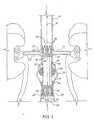
- FIG. 5 and 6An apparatus for deploying a graft within a blood vessel is depicted in Figs. 5 and 6 and identified generally by the reference numeral 100.
- Deployment means 100is elongated to permit delivery of a graft carried thereby to aneurysm 18 via percutaneous entry into a femoral artery of the patient, and may be described as having a near end 102 normally remaining outside the skin of the patient for manipulation by an operating surgeon, and a remote end 104 normally traveling inside the blood vessel lumen during deployment and carrying a graft to be implanted at aneurysm 18.
- Deployment means 100includes an elongated sheath introducer 106 having an axially extending sheath passage 108; an elongated insertion catheter 110 loosely received within sheath passage 108; and an elongated compression spring push rod 112 slidably mounted over insertion catheter 110 and received within sheath passage 108.
- Sheath introducer 106is formed of a low-friction, flexible material, preferably F.E.P., however polyurethane, silicone, polyethylene, or other similar materials may be substituted for PTFE.
- the size of sheath introducer 106is chosen based on the size of the graft to be deployed so as to hold the graft within a remote end of sheath passage 108 in a radially compressed, pre-loaded condition prior to deployment of the graft within the vessel, with sizes 12 FR, 14 FR, 16 FR, 18 FR, and 20 FR being suitable in a vast majority of instances.
- Graft finger portions 46can be pushed together to approximate a conical tip for easier insertion of graft 20 within sheath passage 108, a feature which has resulted a 2 FR reduction in sheath introducer profile relative to loading a similar graft without finger portions 46.
- sheath introducer 106is preferably transparent.
- Sheath introducer 106is equipped with at least one latex-lined hemostasis valve 114 at a near end thereof serving to form a fluid seal around push rod 112 to prevent blood from leaking out of the patient at the entry site.
- a side port means 116is provided for transporting fluid, such as heparinized solution or contrast media, into sheath passage 108 and eventually into the blood vessel.
- Side port means 116includes a manually operable valve 118 communicating with sheath passage 108 through a flexible tube 120 and adapted to receive a suitable fluid injection means (not shown).
- Insertion catheter 110which may be formed of 8 FR catheter tubing, is longer than sheath introducer 106 to permit near and remote ends thereof to extend from sheath introducer 106 when the insertion catheter is received within sheath passage 108. As seen in the cross-sectional view of Fig. 6 , insertion catheter 110 is provided with an embedded, kink-resistant nitinol core wire 122, a first inner track 124, a second inner track 126, and a third inner track 128, all extending lengthwise thereof. Referring once again to Fig.
- a first end port means 130 for transporting fluid to first inner track 124includes a threaded adapter 132 for mating with suitable fluid injection means (not shown) and communicating with a near end of first inner track 124 through a flexible tube 134.
- a second end port means 136 for transporting fluid to second inner track 126includes a manually operable valve 138 communicating with a near end of the second inner track through a flexible tube 140 and adapted to receive a suitable fluid injection means 142.
- a third end port means 144 for transporting fluid to third inner track 128includes a manually operable valve 146 communicating with a near end of the third inner track through a flexible tube 148 and adapted to receive a suitable fluid injection means 150.
- the core wire 122is gradually tapered from a diameter of .031 inches at the near end of insertion catheter 110 to a diameter of .020 inches at the remote end of the insertion catheter. This feature provides that the near end of insertion catheter 110 is strong, and the remote end of the insertion catheter is less likely to cause puncture or rupture of the vessel yet will not deflect significantly under force of blood flow.
- core wire 122provides greatly improved torsional rigidity, whereby rotation at the near end of insertion catheter 110 about its longitudinal axis translates into a substantially equivalent rotation at the remote end of the insertion catheter, such that a graft may be easily rotated during deployment for proper alignment.
- the second inner track 126communicates with a transparent polyurethane tip balloon 152 arranged circumferentially about insertion catheter 110 at the remote end thereof, while third inner track 128 communicates with a transparent polyurethane graft balloon 154 arranged circumferentially about insertion catheter 110 in the vicinity of tip balloon 152.
- Balloons 152 and 154are preferably of the same outside diameter or profile when fully inflated, with graft balloon 154 being longer than tip balloon 152. Balloons-152 and 154 behave in a pressure compliant manner, such that the profile thereof may be continuously and reversibly varied by changing inflation pressure using fluid injection means 142 and 150, respectively.
- Fluid injection meansmay be a syringe having a slidable plunger for observably varying a plenum volume of the syringe, and the plenum volume may be functionally correlated with balloon profile diameter.
- a preferred inflation fluidis filtered carbon dioxide, which is readily visualized by X-ray observation.
- Insertion catheter 110further includes a tapered head 156 adjacent tip balloon 152 for providing a rigid vessel dilator characterized by a smooth atraumatic transition from an 8 FR profile of the insertion catheter to a larger profile of sheath introducer 106.
- Tapered head 156preferably defines an annular abutment lip 158 arranged to engage the remote end of sheath introducer 106 to prevent withdrawal of the tapered head to within sheath passage 108.
- Insertion catheter 110may also be provided with a plurality of circumferential radiopaque markings (not shown) equispaced along the length thereof to assist in location of the insertion catheter during deployment of a graft.
- Push rod 112which is also described in US 5,713,917 , is a metallic compression spring having a combination of flexibility and axial compression strength to enable it to follow the path of a tortuous vessel without losing its ability to act as a push rod for exerting force against a graft during deployment.
- Push rodis sized with inner clearance relative to insertion catheter 110 and outer clearance relative to sheath introducer 106 so as to be independently movable within sheath passage 108.
- a plunger 162is preferably arranged at remote end of push rod 112 for stopping blood flow within sheath passage 108.
- Push rod 112may also include dampening means near its remote end, such as a thin heat-shrunken polyolifin or polyimid coating, to dampen undesirable recoil of the push rod.
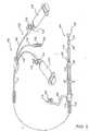
- Push rod 312comprises a handle 313 located towards the proximal or near end 102 of the deployment means 100, coupled to a push rod body 317, which is in turn coupled to a helical coil portion 320.
- a cup 322is located at the distal end of the helical coil portion 320 for containing the distal portion of the stent held within the sheath passage 108.
- the handle 313includes a luer adaptor 314 for coupling with a Tuohy Borst connector(not shown), a lumen 315 extending through the handle 313 for receiving insertion catheter 110, and a female connecting portion 316 for receiving push rod body 317 and push rod stiffener 318.
- the push rod body 317extends distally or remotely of the handle 313 and is made of a polymer material such as polyethylene.
- Push rod body 317has lumen 319 extending through the body for receiving the introducer catheter 110 and push rod stiffener 318.
- Push rod stiffener 318 and push rod body 317are coupled to the handle 313 through female connecting portion 316.
- Push rod stiffener 318provides further support for the flexible push rod body 317 during deployment of the graft.
- the handle 313is used in deploying the graft by holding the graft in place while the sheath covering the graft is retracted.
- the distal end of the push rod body 317is coupled to the helical coil portion 320.
- the helical coil portion 320is preferably made of a helically wound metal material such as stainless steel.
- the helical coil portion 320includes an inner spring 323 threaded inside the helical coil portion 320 at the juncture between the helical coil portion 320 and the push rod body 317.
- the inner spring 323provides for a transition in stiffness between the relatively stiffer push rod body 317 and the more flexible helical coil portion 320.
- the inner spring 323provides a relatively smooth or continuous transition in stiffness from the push rod body 317 to the helical coil portion 320. In this embodiment, the transition occurs from a stiffer push rod body to a more flexible coil.
- a cup 322is threaded into the lumen 321 through the helical coil portion 320.
- the cup opening 327is arranged to receive the distal portion of the graft contained within the sheath passage 108.
- the cup portion 322acts to minimize kinking of the sheath that occurs because of the discontinuity in stiffness between the push rod and the graft.
- the cup portion 322enables the push rod 312 and graft to act as one unit during deployment. Other means for holding or containing the prostheses are contemplated by this invention.
- Examples of such structuresmay include hooks ribbons, wires and posts that engage either the inner or outer lumen of the prosthesis.
- Helical coil portion 320, inner spring 323, and cup 322have lumens 321,325,326 respectively therethrough.
- Lumens 321,325,326,315, and 319provide a continuous opening for receiving insertion catheter 110.
- Figs. 7a and 7billustrate an optional spool apparatus 170 provided as part of deployment means 100 for collapsing a deployed graft and reloading the graft into sheath introducer 106 if unexpected leakage is observed due to incorrect graft position or size.
- Spool apparatus 170is mounted adjacent a near end of sheath introducer 106 by a mounting arm 172, and includes a plurality of suture loops 174 wound around a spool cylinder 176 thereof and arranged to extend through a central axial passage of push rod 112 and around respective crests 40 of a distal spring portion of the graft, as depicted in Fig. 7b .
- a hand crank 178 and releasable pawl(not shown) are provided for rotating and fixing spool cylinder 176 of spool apparatus 170.
- a blade 180is mounted on the body of the spool apparatus for selectively and simultaneously cutting each suture loop 174 at one point to enable removal thereof.
- plunger 162 at the remote end of push rod 112must be omitted to permit suture loops 174 to connect with the distal spring portion of the graft.
- Fig. 8shows a micro-emboli filter tube 182 available for use with deployment means 100 for trapping thrombus dislodged during manipulation of deployment means 100 within the vessel.
- Filter tube 182is adapted to slide over sheath introducer 106 and includes a renal filter 184 and an iliac filter 186.
- Filters 184 and 186are of similar construction and include a plurality of flexible spokes 188 defined by a series of axially extending slits spaced around the circumference of filter tube 182.
- Nylon mesh fabric 190is affixed around the bottom portion of spokes 188, such that when filter tube 182 is axially compressed by pushing a near end thereof while a remote end thereof is held in place by inflated tip balloon 152, spokes 188 flex radially outward to form mesh fabric 190 into a bowl-shaped filter for trapping thrombus entering through gaps between the upper portions of spokes 188.
- the near end of filter tube 182may be pulled while the remote end remains fixed to collapse filters 184 and 186 in preparation for the removal of filter tube 182 from the patient.
- Figs. 9a-9dillustrate a method of surgically deploying single-limb graft 20. It is assumed that necessary mapping of the vessel and aneurysm 18 have been performed, and that an appropriately sized graft 20 has been selected and pre-loaded within a remote end of sheath passage 108 of appropriately sized deployment means 100. It is further assumed that certain equipment used for monitoring and visualization purposes is available for use by a surgeon skilled in the art, including a freely positionable C-arm having high resolution fluoroscopy, high quality angiography, and digital subtraction angiography capabilities.
- the largest femoral artery, left or rightis determined by placing a high flow pig tail angiography catheter (not shown) through a percutaneous entry site in aorta 10 above aorto-renal junction 16 and taking an angiogram; the pig tail catheter is left in place.
- a flexible guide wire 200 preferably having a tip balloon (not shown) at its remote endis introduced into the vessel via a percutaneous entry site in the larger femoral artery, and progressively advanced upward until its tip balloon is above aorto-renal junction 16.
- Deployment means 100pre-filled with heparinized solution through side port means 116, may then be introduced through the femoral entry site and caused to follow guide wire 200 by inserting a near end of the guide wire into first inner track 124 via first end port means 130, and slowly advancing deployment means 100 upward to the site of aneurysm 18.
- contrast mediais injected through first end port means 130 to the remote end opening of first inner track 124 above the renal arteries.
- deployment means 100should be positioned such that proximal spring portion 34 is at or just below renal arteries 12 and 14, and distal spring portion 36 is above the bifurcated aorto-iliac junction and not within aneurysm 18. Blood flow through the region can be obstructed by inflating tip balloon 152 more fully using fluid injection means 142 so as to occlude aorta 10, as depicted in Fig. 9a . With aortic blood flow obstructed, deployment means 100 is rotated so that sheath introducer 106 and compressed graft 20 carried thereby are best aligned to match the bends in the patient's aorta.
- proximal spring portion 34Deployment of proximal spring portion 34 is initiated by withdrawing sheath introducer 106 a short distance, approximately 3.5 cm, while simultaneously holding push rod 112 stationary. The finger portions 46 associated with proximal spring portion 34 will distend as the proximal spring portion is released from within sheath passage 108, and will appear as shown in Fig. 9b . Insertion catheter 110 is then advanced upward to position graft balloon 154 within recently deployed proximal spring portion 34, and the position and alignment of the proximal spring portion relative to renal arteries 12 and 14 is verified by further injection of contrast media through first end port means 130.
- graft balloon 154is inflated to a relatively high pressure to create a smooth vessel wall seat for proximal spring portion 34 and forcibly model the spring portion into conforming fixed engagement with the interior surface of aorta 10 without causing inelastic deformation of the spring portion, as can be seen in Fig. 9c .
- sheath introducer 106With inflated graft balloon 154 reinforcing fixation of proximal spring portion 34, sheath introducer 106 is further withdrawn to a point just before that which is required to release distal spring portion 36 from within sheath passage 108. Once verification has been made that distal spring portion 36 is not going to block either ipsilateral iliac vessel 11 or contralateral iliac vessel 13, sheath introducer may be withdrawn a distance sufficient to release distal spring portion 36 from within sheath passage 108, as depicted in Fig. 9d .
- Blood flowmay then be gently introduced to the newly deployed graft 20 by slowly deflating the graft balloon 154 in small increments.
- Graft balloon 154may be repeatedly deflated, moved downward through graft 20 by increments of approximately 2 cm, and re-inflated to smooth out any wrinkles in graft material 24.
- expandable foam sleeves 58shown in Fig. 1 only surrounding middle portion 29 act to promote clotting in an around aneurysm 18.
- hand crank 178 thereofmay be rotated very slowly in a counterclockwise direction as viewed in Fig. 7a to collapse distal spring portion 36 of graft 20 and reload graft 20 back to within sheath passage 108.
- the sheathmay be pushed upward during reloading of graft 20 to reestablish an abutment seal between annular abutment lip 158 of tapered head 156 and the remote end of sheath introducer 106.
- Deployment means 100may then be gently withdrawn, preferably after partially inflating tip balloon 152 with contrast media, such as carbon dioxide, for visualization. Verification that the removal process has not caused rupture of the vessel or embolization should be undertaken by way of an angiogram through the previously placed pig tail catheter.
- deployment means 100 and guide wire 200may be completely withdrawn from the patient and the entry site attended using standard procedure.
- suture loops 174may be removed by cutting them with blade 180 and rotating hand crank 178 in a counterclockwise direction.
- Tissue adhesivemay then be released from light-degradable packets 56 (shown in Fig. 1 only) by insertion of a fiber optic catheter (not shown) through the femoral artery to graft 20 and direction of light at the packets, thereby helping to bond the graft to the vessel and seal micro-cracks which are a source of leakage.
- Post-operative CAT scan and ultrasound imagingmay be conducted to verify isolation of the aneurysm, with particular attention being given to the occurrence of leaks at proximal spring portion 34 closest to the heart.
- a single-entry method for deploying bifurcated graft 60is procedurally similar to the method described above with regard to single-limb graft 20, however additional steps are necessary to deploy contralateral limb 66 within contralateral iliac vessel 13 with the help of a deflectable-tip guide wire 206 used in place of regular guide wire 200 and having a controllable balloon 208 at a remote end thereof.
- Bifurcated graft 60is pre-loaded into sheath passage 108 with contralateral limb 66 folded alongside primary limb 62, such that as sheath introducer 106 is withdrawn past graft junction 63 subsequent to deployment of proximal spring portion 68A, contralateral limb 66 unfolds generally into aneurysm 18 or the mouth of contralateral iliac vessel 13, as shown in Fig. 10a .
- Retainer ring 79prevents premature expansion of distal spring portion 72B, thereby enabling distal spring portion 72B to be moved within contralateral iliac vessel 13 to a proper position for deployment.
- graft balloon 154is deflated and insertion catheter 110 with inserted deflectable guide wire 206 are withdrawn to the graft junction 63.
- a dial control(not shown) may be used to deflect the remote end of guide wire 206 and direct it into contralateral limb 66 of graft 60.
- Guide wire 206may then be advanced deep into contralateral iliac vessel 13, and tip balloon 208 inflated sufficiently to fix the guide wire within the vessel.
- insertion catheter 110With its own tip balloon 152 partially inflated, insertion catheter 110 is advanced along fixed guide wire 206 into contralateral limb 66 between proximal spring portion 72A and distal spring portion 72B, after which the insertion catheter tip balloon 152 is inflated more fully to allow flow direction of blood to carry graft material 24 of the contralateral limb downward into contralateral iliac vessel 13.
- the distal end of contralateral limb 66is moved to a final desired location by deflating the insertion catheter tip balloon 152 and advancing it to within distal spring portion 72B held by retainer ring 79, partially and carefully re-inflating tip balloon 152 to hold distal spring portion 72B by friction without breaking retainer ring 79, advancing insertion catheter 110 further into contralateral iliac vessel 13 until the distal end of contralateral limb 66 is at the desired location, and finally reinflating the tip balloon to a pressure sufficient to expand or break retainer ring 79 and release distal spring portion 72B, as shown in Fig. 10b .
- Deployment means 100may then be withdrawn and removed from the patient and the entry site attended using standard procedure.
- a method of coaxially coupling extension graft 80 to contralateral limb 66is once again similar to the method described above with regard to single-limb graft 20. While the present method is described herein for coupling extension graft 80 with contralateral limb 66, it will be understood that a similar procedure may be followed to deploy extension graft 80 in coupled relation with ipsilateral limb 64.
- extension graft 80is deployed via percutaneous entry through the contralateral femoral artery.
- a guide wire 200 having a controllable tip balloon 202is advanced upward through contralateral limb 66 and into primary limb 62 of previously deployed bifurcated graft 60, and deployment means 100 carrying pre-loaded extension graft 80 is directed over guide wire 200, again using first inner track 124, and advanced to a position wherein mating portion 82 of extension graft 80 is partially within contralateral limb 66, preferably with first spring portion 88A of mating portion 82 overlapped by distal spring portion 72B of bifurcated graft 60.
- Sheath introducer 106is then withdrawn while push rod 112 is held stationary in order to release first spring portion 88A.
- insertion catheter 110is advanced upwards to locate graft balloon 154 within first spring portion 88A, and the graft balloon is inflated to a relatively high pressure. Contrast media may then be injected as previously described to verify that the coupled graft limbs are not leaking.
- sheath introducer 106is further withdrawn to successively release second spring portion 88B and third spring portion 90 from sheath passage 108, with third spring portion 90 remaining in a compressed condition due to retainer ring 91.
- Graft balloon 154is then deflated and moved downward to within third spring portion 90, and partially re-inflated to hold the third spring portion by friction, with care being taken so as not to overinflate graft balloon 154 and expand or break retainer ring 91. This permits the distal end of adjustable length portion 84 to be positioned generally just above the sub-iliac or hypogastric branch by further withdrawing insertion catheter 110.
- Third spring portion 90is deployed by inflating graft balloon 154 therewithin to a relatively high pressure sufficient to expand or break surrounding retainer ring 91, as depicted in Fig. 11 , and fix the third spring portion in conformance with the interior surface of contralateral iliac vessel 13. Any wrinkles in extension graft 80 may be removed using graft balloon 154 as previously described herein. Finally, once leakage has been ruled out, such as by angiogram verification, deployment means 100 may be withdrawn from the patient and the entry site attended.
- the delivery system of the present invention and in particular the aspects regarding the flexible , compressible push rodmay be used in deploying other endoluminal prostheses where the prosthesis is retained in the shaft of a catheter for delivery to an endoluminal site.
- Endoluminal prostheseswhich terms are herein intended to mean medical devices which are adapted for temporary or permanent implantation within a body lumen, including both naturally occurring or artificially made lumens.
- endoluminal prosthesesexamples include, without limitation: arteries such as those located within coronary, mesentery, peripheral, or cerebral vasculature; veins; gastrointestinal tract; biliary tract; urethra; trachea; hepatic shunts; and fallopian tubes.
- arteriessuch as those located within coronary, mesentery, peripheral, or cerebral vasculature
- veinssuch as those located within coronary, mesentery, peripheral, or cerebral vasculature
- gastrointestinal tractsuch as those located within coronary, mesentery, peripheral, or cerebral vasculature
- biliary tractbiliary tract
- urethraurethra
- tracheahepatic shunts
- fallopian tubesa type of endoluminal prostheses have also been developed, each providing a uniquely beneficial structure to modify the mechanics of the targeted luminal wall.
Landscapes
- Health & Medical Sciences (AREA)
- Life Sciences & Earth Sciences (AREA)
- Engineering & Computer Science (AREA)
- Biomedical Technology (AREA)
- Heart & Thoracic Surgery (AREA)
- Surgery (AREA)
- Veterinary Medicine (AREA)
- Animal Behavior & Ethology (AREA)
- General Health & Medical Sciences (AREA)
- Public Health (AREA)
- Vascular Medicine (AREA)
- Medical Informatics (AREA)
- Molecular Biology (AREA)
- Reproductive Health (AREA)
- Nuclear Medicine, Radiotherapy & Molecular Imaging (AREA)
- Cardiology (AREA)
- Transplantation (AREA)
- Oral & Maxillofacial Surgery (AREA)
- Pulmonology (AREA)
- Child & Adolescent Psychology (AREA)
- Biophysics (AREA)
- Anesthesiology (AREA)
- Hematology (AREA)
- Gastroenterology & Hepatology (AREA)
- Neurosurgery (AREA)
- Prostheses (AREA)
- Surgical Instruments (AREA)
- Media Introduction/Drainage Providing Device (AREA)
Abstract
Description
- The present invention relates to blood vessel graft systems for repairing aneurysms, and more particularly to a catheter-based graft system for repairing aortic aneurysms by deploying a graft within a blood vessel via percutaneous entry into a femoral artery of a patient.
- An aortic aneurysm is a very common deteriorating disease typically manifested by weakening and expansion of the aorta vessel wall at a region between the aorto-renal junction and the aorto-iliac junction. Aneurysms affect the ability of the vessel lumen to conduct fluids, and may at times be life threatening, for instance when rupture of the vessel wall occurs. A standard treatment for repairing an aneurysm is to surgically remove part or all of the aneurysm and implant a replacement prosthetic section into the vessel, however such surgery is generally postponed until the aneurysm has grown to a diameter greater than five centimeters. With aneurysms over five centimeters in diameter, the risk of complications is greater than the risks inherent in surgical excision and grafting of the aneurysm. Consequently, aortic aneurysms measuring greater than five centimeters in diameter, and those showing a rapid increase in size, are generally surgically removed and grafted as a matter of course, before rupture occurs.
- The standard procedure for repairing an aortic aneurysm requires one or two days of preparing the large and small intestines prior to hospitalization. The operation itself generally takes one to three hours to perform, and necessitates several units of blood for transfusion. The patient commonly remains hospitalized for several days following surgery, and requires as much as three months recuperation time before returning to work. Moreover, there remain significantly high rates of mortality and morbidity associated with the standard procedure. The mortality rate is as high as eight percent, while the morbidity rate includes incident complications such as blood loss, respiratory tract infections, wound infections, graft infections, renal failure, and ischemia of the bleeding intestine. The mortality and morbidity rates for this type of major surgery are also often influenced by the fact that the typical aortic aneurysm patient is elderly and therefore less able to withstand major surgery, including anesthesia.
- Other treatments for repairing an aneurysm involve deploying a graft device at the aneurysm site via a catheter traveling through a femoral artery. Conventional tubular aortic replacement sections, however, are generally considerably larger in diameter than the femoral artery and therefore cannot be inserted through the femoral artery lumen to the site of the aneurysm. Expandable graft devices suitable for catheter delivery and deployment have been proposed, as in
U.S. Patent Nos. 4,140,126 and4,562,596 by Choudhury and Kornberg , respectively, however the expanding structures of the devices are cumbersome and difficult to operate. U.S. Patent No. 5,104,399 to Lazarus discloses an artificial graft device having staples at proximal and distal ends thereof for fixing the graft within the vessel, and a catheter-based deployment system including a tubular capsule from which the graft is deployed. The graft is of a preselected cross section and length, and is capable of being substantially deformed so as to accommodate to the interior surface of the blood vessel.- The majority of other graft systems, as exemplified by
U.S. Patent Nos. 5,304,220 to Maginot and5,151,105 to KwanGett , require additional suturing or other methods for securing a graft. Furthermore, once a graft has been placed inside the lumen, adjustment usually requires a major surgical procedure. - Furthermore, the prior art stainless steel or elgialloy stent grafts carry high leakage rates. Moreover, high incidence of fractures have been associated with stainless steel stent grafts.
- An additional problem with grafts in the public domain is the graft in-folding which causes leakage, migration, and thrombosis. Too, those grafts in the public domain such as
U.S. Patent bearing No. 5,507,771 can provide adequate seals only with straight surfaces due to the spring shape and sealing force. - In cases where the aneurysm involves the ipsilateral and contralateral iliac vessels extending from the aorta, it is known to provide a generally Y-shaped bifurcated graft having a primary limb joining with an ipsilateral limb and a contralateral limb. An example of such a graft, and means for surgically implanting same, are described in
U.S. Patent No. 5,387,235 to Chuter. The surgical procedure taught by Chuter involves either surgical isolation of the femoral vessels in the groin to provide direct access to the vessels, or percutaneous entry through both ipsilateral and contralateral femoral arteries. - The difficulties involved with traditional surgical procedures and additional complexities associated with securing grafts make the treatment of aneurysms a very expensive and lengthy procedure. Thus, there exists a need for a treatment for aneurysms which requires minimal preparation and outpatient care, and which provides a safe and percutaneous method for deploying a graft capable of remaining in place without additional suturing or stapling for security:
US 5,275,622 describes an endovascular grafting apparatus having a pusher button that forces a graft (prosthesis) out of a capsule (sheath passage). The pusher button is carried by a balloon catheter shaft. The balloon catheter shaft is the only element carrying the compressive load from the proximal end of the catheter to the graft (prosthesis). The balloon catheter shaft has the same flexibility in its near portion as it has in its remote portion, since its size and cross section is unchanged.- For deployment of a prosthesis or graft the pusher button carried by the balloon catheter shaft is in engagement with the proximal extremity of the graft to force the graft out of the capsule as the capsule is withdrawn.
US 6,146,389 describes a stent deployment device for deploying a stent within a body cavity comprising an endoscope with a protective cap, a flexible stent, a sheath, and a flexible elongated member.- The endoscope has the protective cap mounted onto its distal end. The stent is circumferantially wrapped and compressed around and over the perimeter of the cap. The sheath is wrapped around the stent to hold it in a compressed configuration over the cap. Once the sheath is removed from cap and the stent in the body cavity by pulling the elongated member toward the near end of the endoscope, the stent deploys within the body cavity.
EP 0 990 426 describes a disposable delivery device for endoluminal prosthesis. The delivery system comprises a tubular sheath and a shaft. The shaft is slidably received within a lumen of the sheath. A plurality of runners extend distally from the shaft. A prosthesis is radially compressed and restrained within the runners and is deployed by relative movement of shaft and sheath.- However,
EP 0 990 426 is silent about special characteristics of the shaft. US 6,208,888 describes a stent delivery system using shaped memory retraction. A catheter comprises an inner shaft and an outer shaft. Connected to the outer shaft is a retraction assembly, which is comprised of a collapsible accordian section and a stent sheath section. A shape memory contraction member connected to a retractable outer sheath causes an annular collar to be retracted proximally, collapsing an accordian section of the retractable outer sheath and retracting a stent sheath so that the medical device such as stent can be delivered.US 5,643,278 A describes a catheter assembly for the delivery of a vascular stent into human arteries and veins. Wherein, a spring coil is attached on its proximal end to a polymer sheath and positioned on its distal end to cover at least a portion of a stent. The stent is seated on or optionally glued to a balloon, which can be moved relatively to the spring coil by means of an elongated support member. The stent is deployed by withdrawing the spring wire coil covering the proximal end of the stent from the stent to release it and then inflating the balloon, if the stent is not self-expanding.- Therefore, it is an object of the present invention to provide a graft which is deployable percutaneously by low-profile deployment means, and which provides a leak-proof conduit through the diseased region without suturing or stapling.
- It is another object of the present invention to provide a bifurcated graft deployable through a single entry site.
- It is yet another object of the present invention to provide an adjustable-length extension graft for coupling with a limb of a previously deployed graft.
- It is yet another object of the present invention to provide low-profile graft deployment means capable of securely deploying a graft via percutaneous entry.
- It is yet another object of the present invention to provide deployment means having inflatable and deflatable balloons for modeling a graft spring portion into conforming fixed engagement with the interior surface of a vessel, for dilating a vessel to facilitate insertion, and for controlling blood flow through a vessel during deployment of a graft.
- It is yet another object of the present invention to establish an improved method for securely deploying a graft with minimal incision.
- It is yet another object of the present invention to establish a method for implanting a graft with low mortality and low morbidity risks to patients.
- It is yet another object of the present invention to establish a method for implanting a graft which requires less hospital and outpatient care than required by normal surgical grafting procedures.
- It is yet another object of the present invention to establish a single-entry method for deploying a bifurcated graft.
- It is yet another object of the present invention to provide means for easily adjusting or removing an improperly deployed graft.
- The present invention relates to an aneurysm repair system, wherein a graft apparatus can be placed percutaneously via deployment means at the location of an aneurysm. It will be understood the term "proximal" as used herein means relatively closer to the heart, while the term "distal", as used herein means relatively farther from the heart.
- The graft apparatus comprises a tubular graft formed of bio-compatible graft material for conducting fluid, and may be in the form of either a straight single-limb graft or a generally Y-shaped bifurcated graft having a primary limb joining with a pair of lateral limbs, namely an ipsilateral limb and a contralateral limb, at a graft junction. A single-limb extension graft having a mating portion for coupling with a lateral limb of a bifurcated graft and an adjustable length portion extending coaxially from a distal end of the mating portion could also be employed The graft material, preferably thin wall woven polyester or polytetrafluoroethylene (PTFE), is chosen so that the graft is capable of substantially deforming to conform to an interior surface of the blood vessel, and is preferably tapered through a middle portion of each limb. Other covering materials may be used, however, including microporous polyurethane, lycra, or cryogenically preserved explanted veins. The most useful covering material is Lycra outside with thin PTFE inside at top proximal section with bare nitinol sinusoidal extension for above renal artery fixation. Further, for the aortic section, having aortic wall movement of approximately 3MMS per heart beat, polyester (Dacron) is a preferred covering material. Moreover, with respect to grafts used in the iliac artery sections, where there is very little wall movement, PTFE is a preferred graft covering material. In the adjustable length portion of the extension graft, the graft material is crimped to permit axial or lengthwise extension and compression thereof.
- The graft apparatus includes radially compressible spring means, preferably in the form of a nitinol wire spring having a pair of coaxially spaced annular spring portions connected by a connecting bar, for biasing proximal and distal ends of an associated graft limb or limb portion radially outward into conforming fixed engagement with the interior surface of the vessel. In the extension graft, an unpaired annular spring portion is located at a distal end of the adjustable length portion for similar biasing purposes. Each wire spring is enclosed by the graft material and stitched thereto, with cut-out portions being provided between spokes of the wire spring to define a plurality of radially distensible finger portions at the ends of the graft. A distal end of the contralateral limb of the bifurcated graft, and the distal end of the adjustable length portion of the extension graft, are each provided with a retainer ring to retain respective spring portions associated therewith in a radially compressed or loaded condition during deployment.
- The graft apparatus could further comprise a plurality of outer packets formed of a light degradable polymer and containing a tissue adhesive which is released by fiber-optic scope after the graft is implanted to bond the ends of the graft to the interior surface of the vessel and prevent leakage through micro-cracks therebetween. Medical grade expandable foam cuffs preferably surround the middle portion of the graft to promote clotting within the aneurysm sac. Alternatively, light actuated cryo precipitate fibrin glue may be painted onto the exterior surface of the graft material with a brush. The adhesive naturally remains as syrup until light actuates and cures. This replaces the need for packets and reduces the possibility of premature release of adhesive from packets that may break during deployment.
- The deployment means generally comprises an elongated sheath introducer having an axially extending sheath passage for slidably receiving the graft and maintaining the graft and associated spring means in a radially compressed pre-loaded condition prior to deployment of the graft within the vessel lumen, an elongated insertion catheter received within the sheath passage and pre-loaded graft for use in guiding the graft to the location of the aneurysm and deploying the graft within the vessel lumen at such location, and a flexible condensing spring push rod slidably arranged about the insertion catheter and received within the sheath passage to abut with the graft for navigating through tortuous vessels and pushing the graft out of the sheath passage during deployment. Deployment means may also comprise a micro-emboli filter tube selectively slidable over the sheath introducer and having controllable renal and iliac filters which may be opened to catch thrombus dislodged into the blood stream.
- The push rod could comprise a helical coil member. In this case the push rod has a continuously variable stiffness so that the push rod may move flexibly throughout a tortuous vessel with minimal kinking of the sheath or other portions of the delivery system.
- The insertion catheter includes an embedded kink-resistant nitinol core wire and three inner tracks extending lengthwise thereof. A first inner track opens at both a near end and a remote end of the insertion catheter for receiving a guidewire to guide the insertion catheter through the vessel lumen. A second inner track opens at the near end of the insertion catheter for allowing fluid communication with an inflatable and deflatable tip balloon located at the remote end of the insertion catheter for dilating the vessel ahead of the graft and controlling blood flow through the vessel during placement. A third inner track opens at the near end of the insertion catheter for allowing fluid communication with an inflatable and deflatable graft balloon located near the remote end of the insertion catheter generally for securing the graft spring means against the interior surface of the vessel during graft deployment.
- An optional spool apparatus may also be incorporated into the deployment means for collapsing a deployed graft and reloading the graft into
sheath introducer 106 if unexpected leakage is observed due to incorrect graft position or size. The spool apparatus is connected to the sheath introducer and includes a plurality of suture loops wound around a spool cylinder and arranged to extend through a central axial passage of the push rod and around respective crests of a distal spring portion of the graft. A hand crank enables rotation of the spool cylinder to collapse the distal spring and pull it to within the sheath introducer, and a blade is provided on the spool apparatus for cutting each suture loop at one point to permit removal of the suture material if repositioning or removal of the graft is unnecessary. - A method of surgically implanting a pre-sized single limb graft to repair a previously-mapped aortic aneurysm using the deployment means may be summarized as follows, keeping in mind that fluoroscopic or other monitoring means known in the art may be employed throughout the procedure.
- First, a guide wire is introduced into the vessel via a femoral percutaneous entry and progressively inserted until a remote end of the guide wire extends upward past the aorto-renal junction, and the insertion catheter with surrounding pre-loaded graft, push rod, and sheath introducer are caused to follow the guidewire through the vessel lumen using the first inner track of the insertion catheter until the tip balloon is above the aorto-renal junction. The tip balloon may be partially inflated during insertion of the deployment means to dilate the vessel for easier introduction, and once properly positioned, may be inflated further so as to obstruct blood flow in the aorta just above the aorto-renal junction. With aortic blood flow obstructed, the insertion catheter is rotated so that the sheath introducer and compressed graft therewithin are best aligned to match the bends in the patient's aorta. Next, the spring portion associated with the proximal end of the graft is observed for correct axial alignment within the vessel at a location just below the aorto-renal junction.
- Once proper positioning and alignment of the apparatus are observed, the sheath introducer is withdrawn a short distance while holding the push rod in place to release the proximal spring portion of the graft from within a remote end of the sheath passage and allow it to expand radially outward to conform with the interior surface of the vessel, with verification being made that the proximal spring portion continues to be in correct position. The operator may remove the guidewire from the first inner track and inject contrast media into the first inner track, or may place an ultrasound imaging catheter, for purposes of visualization. Next, the insertion catheter is moved upward within the vessel to align the graft balloon to within the proximal spring portion of the graft, and the graft balloon is inflated with relatively high pressure to fixedly model the proximal spring portion against the interior surface of the vessel. The sheath introducer may now be withdrawn further to fully deploy the graft, including the distal spring portion, which should be located at a healthy region below the aneurysm.
- Blood flow may then be gently introduced to the graft by slowly deflating the tip balloon. The graft balloon may be repeatedly deflated, moved incrementally along the central axis of the graft, and re-inflated to smooth out any wrinkles in the graft material. When the graft balloon has traveled down the graft to within the distal spring portion, it may again be inflated at a relatively high pressure to fix the distal spring in conformance with the inner surface of the vessel. If it is observed that the graft is not in its intended position, the spool apparatus may be used to reload the graft within the sheath introducer.
- Once the graft is correctly deployed, the deployment means may be completely withdrawn from the patient, and a fiber-optic scope inserted through the entry site to direct light at the tissue adhesive packets to cause the packet polymer material to degrade, thereby releasing the tissue adhesive. Finally, the entry site attended using standard procedure. Post-operative imaging may be conducted to verify isolation of the aneurysm, with particular attention being given to the occurrence of leaks at the proximal end of the graft closest to the heart.
- A single-entry method of surgically implanting a pre-sized bifurcated graft in cases where mapping of the aneurysm indicates involvement of one or both iliac vessels is described in the following.
- Deployment of the bifurcated graft is carried out by a method similar to that used to implant a single-limb graft, except that additional procedures are required to properly implant a contralateral limb of the bifurcated graft within a contralateral iliac vessel. As the sheath introducer is withdrawn to deploy the primary leg of the graft within the aorta, the contralateral limb of the graft will be released from the sheath introducer when the sheath introducer has been withdrawn just past the graft junction, such that the contralateral limb of the graft is within the aneurysm sac or directed downward into the contralateral iliac vessel. The retainer ring at the distal end of the contralateral limb prevents premature expansion of the spring portion associated with such end to permit proper positioning of the contralateral limb within the contralateral iliac vessel.
- Positioning of the contralateral limb is carried out using the insertion catheter and a deflectable guide wire inserted within the first inner track of the insertion catheter and having an inflatable and deflatable tip balloon at a remote end thereof. First, the graft balloon is deflated and the insertion catheter with inserted deflectable guide wire are withdrawn to the graft junction. A dial control may be used to deflect the remote end of the guide wire and direct it into the contralateral limb of the graft; the guide wire is then advanced deep into the contralateral iliac vessel and the tip balloon thereof is inflated to anchor the guide wire within the vessel. With its own tip balloon partially inflated, the insertion catheter is advanced along the anchored guide wire into the contralateral limb of the graft. The insertion catheter tip balloon is then inflated more fully to allow flow direction of blood to carry graft material of the contralateral limb down the contralateral iliac vessel. The contralateral limb is moved to a final desired location by deflating the insertion catheter tip balloon and advancing it to within the spring portion at the distal end of the contralateral limb held by the retainer ring, partially reinflating the tip balloon to hold the distal end and associated distal spring portion of the contralateral limb by friction, advancing the insertion catheter into the contralateral iliac vessel until the distal end of the contralateral limb is at the desired location, and finally reinflating the tip balloon fully to expand or break the retainer ring and release the spring portion. The deployment means may then be withdrawn and removed from the entry site and the entry site attended using standard procedure.
- If the extent of disease indicates that a longer graft limb is necessary in either or both iliac vessels, an adjustable length extension graft may be coaxially coupled to a lateral limb, for instance the contralateral limb, of the bifurcated graft by the following procedure.
- The extension graft is deployed via percutaneous entry through the contralateral femoral artery. A guide wire is directed through the contralateral limb and up into the primary limb of the bifurcated graft, and deployment means carrying a pre-loaded extension graft is directed over the guidewire to position the mating portion of the extension graft partially within the contralateral limb of the bifurcated graft such that a first spring portion at the proximal end of the mating portion is overlapped by the spring portion at the distal end of the contralateral limb. The sheath introducer may then be withdrawn while the push rod is held stationary to deploy the first spring portion, the insertion catheter moved upwards to locate the graft balloon within the first spring portion, and the graft balloon inflated to conform the first spring portion to the interior surface of the contralateral limb. Contrast media is injected through the first inner track of the insertion catheter to verify that the coupled graft limbs are not leaking. Next, the sheath introducer is further withdrawn to release a second spring portion defining a junction between the mating and adjustable-length portions, and a third spring portion at a distal end of the adjustable-length portion the radially retained distal annular spring of the adjustable length portion, into the contralateral iliac vessel. The graft balloon is then deflated and moved downward to within the third spring portion, and partially re-inflated to hold the distal end of the adjustable-length portion by friction. This permits the distal end of the adjustable-length portion to be positioned generally just above the sub-iliac or hypo-gastric branch by withdrawing the insertion catheter downward. The third spring portion is deployed by fully reinflating the graft balloon therewithin to expand or break the surrounding retainer ring and fix the third spring portion in conformance with the interior surface of the vessel. Any wrinkles in the extension graft may be removed using the graft balloon. Finally, once leakage has been ruled out, such as by angiogram verification, the deployment means may be withdrawn and the entry site attended.
- The nature and mode of operation of the present invention will now be more fully described in the following detailed description taken with the accompanying drawings wherein:
Fig. 1 is an elevational view showing a single-limb graft fully deployed within an aorta of a patient to repair an aneurysm;Fig. 2 is a view similar to that ofFig. 1 , however showing an optional anchor spring attached to the graft for suprarenal fixation of the graft;Fig. 3 is an elevational view showing a bifurcated graft fully deployed within an aorta and lateral iliac vessels joined therewith;Fig. 4 is a view similar to that ofFig. 3 , however showing an extension graft for coupling with a lateral limb of the bifurcated graft;Fig. 5 is a perspective view showing a graft deployment meansFig 5A is an elevational view of an embodiment of a push rod of the present invention.Fig. 5B is an exploded elevational view of the push rod ofFig 5A Fig. 6 is a sectional view thereof taken generally along the line 6-6 inFig. 5 ;Fig. 7a is a perspective view showing a spool apparatus ;Fig. 7b is an enlarged partial view of circled portion A inFig. 7a showing the arrangement of a suture loop of the spool apparatus;Fig. 8 is an elevational view showing a micro-emboli filter tube in an activated condition;Figs. 9a-9d are a series of elevational views illustrating a method of deploying a single-limb graft ;Figs. 10a and10b are elevational views illustrating a method of deploying a bifurcated graft ; andFig. 11 is an elevational view illustrating a method of deploying an extension graft for coupling with a lateral limb of a bifurcated graft .- Referring initially to
Fig. 1 , there is shown anaorta 10 joined byrenal arteries renal junction 16, and having ananeurysm 18 below the aorto-renal junction characterized by a weakened and expanded vessel wall at the diseased region. An elongated single-limb tubular graft 20 is deployed at the region ofaneurysm 18 as a prosthetic device for the purpose of relieving blood flow pressure against the weakened vessel wall by acting as a fluid conduit through the region of the aneurysm. In its deployed condition,graft 20 defines a centrallongitudinal axis 22 extending in a direction of blood flow throughaorta 10, and generally comprises adeformable graft material 24 enclosing radially compressible spring means 26 for biasing aproximal end 28 and adistal end 30 of the graft into conforming fixed engagement with an interior surface ofaorta 10. Graft material 24 is a biocompatible, flexible and expandable, low-porosity woven fabric, for example thin-walled polyester or PTFE, capable of substantially deforming to conform with an interior surface ofaorta 10, and additionally capable of acting as a fluid conduit when in tubular form. Amiddle portion 29 ofgraft 20 betweenproximal end 28 anddistal end 30 is tapered to provide a decreased fluid-conducting cross-sectional area relative to ends 28 and 30, such as by excising at least one longitudinal strip ofgraft material 24 and sewing the resulting gap or gaps closed, as a way of reducing the occurrence of folding and wrinkling and adapting the graft to fit within a wider range of differently sized vessels.- Enclosed within
graft material 24 is a nitinol wire spring having aproximal spring portion 34 and adistal spring portion 36. Alternatively, theproximal spring portion 34 may have uncovered portions or open areas proximal of the graft material so that in the event thespring portion 34 is deployed over therenal arteries arteries Spring portions graft material 24 at graft ends 28 and 30 into conforming fixed engagement with the interior surface ofaorta 10 above and belowaneurysm 18. The nitinol wire used to form the spring is in a super elastic, straight annealed condition and may be coated with titanium oxide to improve biocompatibility, reduce the incidence of allergic reaction to nickel, and improve radiopacity. A PTFE coating may also be used to lower the risks of blood clotting and wire corrosion. As a further preventive measure, the coating may be treated with iridium 192 or other low dose Beta radiation emitting substance to reduce post-surgical cell proliferation in the vessel which can lead to closure of the vessel.Spring portions straight spokes 38 connected by rounded alternatingcrests 40 andtroughs 42 aboutcentral axis 22 to provide a continuous annular spring portion. A preferred spring portion includes fiveequispaced crests 40 and fiveequispaced troughs 42 formed to a predetermined radius to produce better spring properties and avoid sharp transitions in the wire, in that sharp transitions are more prone to failure. The coaxially spacedspring portions bar 44 which preferably extends generally parallel tocentral axis 22 for minimal disruption of blood flow. Connectingbar 44 provides torsional stability forgraft 20, and may be welded tospring portions - The wire spring is sewn within
graft material 24 using polyester suture. Prior to sewing,graft material 24 is arranged to surround the wire spring and is heat pressed to conform tospring portions graft material 24 to the wire spring. This method of attachment substantially prevents contact between wire spring and the interior surface of the vessel, and is reliable over time. Thegraft material 24 is cut out betweencrests 40 ofproximal spring portion 34 anddistal spring portion 36 to define a plurality of radiallydistensible finger portions 46 at graft ends 28 and 30. Importantly,finger portions 46 allowgraft 20 to be situated withproximal end 28 much closer to aorto-renal junction 16 , since gaps between the finger portions may be aligned withrenal arteries finger portions 46 may be radially compressed to approximate a conical tip to facilitate loading insertion ofgraft 20 within a sheath introducer, to be described hereinafter. As shown inFig. 2 , a bare nitinolwire anchor spring 48 may be used to provide increased positional integrity to graft 20 where healthy vessel neck between aorto-renal junction 16 andaneurysm 18 is particularly short.Anchor spring 48 includes aproximal spring portion 50 set approximately 20 mms above aorto-renal junction 16 for suprarenal fixation remotely of graftproximal spring portion 34, and adistal spring portion 52 sewn within graftmiddle portion 29 and connected toproximal spring portion 50 by at least one axially extending connectingbar 54. The provision of radiallydistensible finger portions 46 andoptional anchor spring 48 makes it possible that only about 5 mms of healthy vessel neck below the aorto-renal junction is required as compared with about 20 mms for former graft systems. Graft 20 further includes a plurality of releasable tissueadhesive packets 56 fixed to an exterior surface ofgraft material 24 at ends 28 and 30 for establishing a fluid tight seal betweengraft material 24 and the inner wall ofaorta 10.Packets 56 may be constructed of photosensitive polyurethane and filled with biocompatible tissue adhesive, for example fibrin glue or isobutyl 2 cyanoacrylate. The tissue adhesive remains secure during deployment, and may subsequently be released by directing a fiber-optic catheter light source atpackets 56 frominside graft 20 to cause breakdown of the packet material. Tissue adhesive enters and occupies small micro-cracks existing betweengraft material 24 and the interior surface ofaorta 10 to form a bonding fluid seal, thereby preventing the serious problem of leakage. An alternative to the described tissue adhesive packets is the use of light activated cryo precipitate fibrin glue painted on the exterior surface of the graft material.- In addition to tissue
adhesive packets 56 at ends 28 and 30, one ormore cuffs 58 comprising medical-grade expandable foam may be provided to surroundmiddle portion 29 to promote clotting in the space of the aneurysm outside ofgraft 20. First and second cuffs expandable to approximately 4-10 mms greater than the graft diameter are arranged nearspring portions Cuffs 58 preferably include fetal endothelial cells, smooth muscle cells, or other living tissue cells and glioma growth factor in their respective foam matrices or light activated foaming particles to encourage healing nearspring portions aneurysmal sac 18 aroundmiddle portion 29. - 29. A
bifurcated graft 60 as shown inFig. 3 could be used in cases where involvement of one or bothiliac vessels Graft 60 is Y-shaped and includes aprimary limb 62 for location withinaorta 10, and is joined by anipsilateral limb 64 for location within ipsilateraliliac vessel 11, and by acontralateral limb 66 for location within contralateraliliac vessel 13, at agraft junction 63. Each limb ofbifurcated graft 60 is generally similar in construction to single-limb graft 20 in that the proximal and distal ends of each limb are biased into conforming fixed engagement with the interior surface of a corresponding vessel by annular spring portions associated therewith, and middle portions of each limb are preferably tapered. A first nitinol wire spring is enclosed by, and attachably sewn within,graft material 24 and includes aproximal spring portion 68A associated with a proximal end ofprimary limb 62, adistal spring portion 68B associated with a distal end ofprimary limb 62, and an axially extending connectingbar 68C coupling the proximal and distal spring portions together. Similarly, a second nitinol wire spring having aproximal spring portion 70A, adistal spring portion 70B, and an axially extending connectingbar 70C, is sewn withinipsilateral limb 64; and a third nitinol wire spring having aproximal spring portion 72A, adistal spring portion 72B, and an axially extending connectingbar 72C, is sewn withincontralateral limb 66. Terminal ends ofbifurcated graft 60, namely the proximal end ofprimary limb 62 and the distal ends oflateral limbs distensible finger portions 46 as described above. Where entry is to be made through an ipsilateral femoral artery to deploygraft 60,distal spring portion 72B is held in a radially compressed condition by anexpandable retainer ring 79, which may simply be a length of suture material tied end to end using a purse-string type knot to form a loop, to prevent premature deployment ofdistal spring portion 72B prior to proper positioning thereof within contralateraliliac vessel 13. Likewise, where entry is to be made through a contralateral femoral artery,distal spring portion 70B may be provided with aretainer ring 79 to prevent premature deployment ofdistal spring portion 70B prior to proper positioning thereof within ipsilateraliliac vessel 11. It will be understood that previously described tissueadhesive packets 56 andfoam cuffs 58, while not shown inFig. 3 , may be incorporated into bifurcatedgraft 60. Specifically,packets 56 are preferably provided at least at the proximal end ofprimary limb 62 to prevent leaking, andfoam cuffs 58 are preferably provided around the primary limb for fillinganeurysmal sac 18. - A single-
limb extension graft 80, as depicted inFig. 4 , embodies another useful apparatus of the present invention.Extension graft 80 is designed for end-to-end coupling with a lateral limb ofbifurcated graft 60, for examplecontralateral limb 66, and generally includes amating portion 82 and anadjustable length portion 84 extending coaxially from a distal end of the mating portion.Mating portion 82 includes a wire spring having afirst spring portion 88A serving to bias a proximal end ofmating portion 82 into conforming fixed engagement with an interior surface ofcontralateral limb 66, and asecond spring portion 88B connected tofirst spring portion 88A by a connectingbar 88C serving to bias a distal end ofmating portion 82 and a proximal end ofadjustable length portion 84 into conforming fixed engagement with the interior surface of contralateraliliac vessel 13. An unpairedthird spring portion 90 is provided at a distal end ofadjustable length portion 84 to bias such end against the interior surface of contralateraliliac vessel 13, and is maintained in a radially compressed condition prior to deployment by abreakable retainer ring 91 similar toretainer ring 79.Third spring portion 90 is movable in opposite axial directions to a desired location during deployment by virtue of a crimped length of graft material provided inadjustable length portion 84. - As will be appreciated by those skilled in the art, the above described
grafts - An apparatus for deploying a graft within a blood vessel is depicted in
Figs. 5 and6 and identified generally by thereference numeral 100. Deployment means 100 is elongated to permit delivery of a graft carried thereby toaneurysm 18 via percutaneous entry into a femoral artery of the patient, and may be described as having anear end 102 normally remaining outside the skin of the patient for manipulation by an operating surgeon, and aremote end 104 normally traveling inside the blood vessel lumen during deployment and carrying a graft to be implanted ataneurysm 18. Deployment means 100 includes anelongated sheath introducer 106 having an axially extendingsheath passage 108; anelongated insertion catheter 110 loosely received withinsheath passage 108; and an elongated compressionspring push rod 112 slidably mounted overinsertion catheter 110 and received withinsheath passage 108. Sheath introducer 106 is formed of a low-friction, flexible material, preferably F.E.P., however polyurethane, silicone, polyethylene, or other similar materials may be substituted for PTFE. The size ofsheath introducer 106 is chosen based on the size of the graft to be deployed so as to hold the graft within a remote end ofsheath passage 108 in a radially compressed, pre-loaded condition prior to deployment of the graft within the vessel, withsizes 12 FR, 14 FR, 16 FR, 18 FR, and 20 FR being suitable in a vast majority of instances.Graft finger portions 46 can be pushed together to approximate a conical tip for easier insertion ofgraft 20 withinsheath passage 108, a feature which has resulted a 2 FR reduction in sheath introducer profile relative to loading a similar graft withoutfinger portions 46. In order to permit viewing of a pre-loaded graft to confirm proper loading,sheath introducer 106 is preferably transparent.Sheath introducer 106 is equipped with at least one latex-linedhemostasis valve 114 at a near end thereof serving to form a fluid seal aroundpush rod 112 to prevent blood from leaking out of the patient at the entry site. A side port means 116 is provided for transporting fluid, such as heparinized solution or contrast media, intosheath passage 108 and eventually into the blood vessel. Side port means 116 includes a manually operable valve 118 communicating withsheath passage 108 through aflexible tube 120 and adapted to receive a suitable fluid injection means (not shown).Insertion catheter 110, which may be formed of 8 FR catheter tubing, is longer thansheath introducer 106 to permit near and remote ends thereof to extend fromsheath introducer 106 when the insertion catheter is received withinsheath passage 108. As seen in the cross-sectional view ofFig. 6 ,insertion catheter 110 is provided with an embedded, kink-resistantnitinol core wire 122, a firstinner track 124, a secondinner track 126, and a thirdinner track 128, all extending lengthwise thereof. Referring once again toFig. 5 , a first end port means 130 for transporting fluid to firstinner track 124 includes a threadedadapter 132 for mating with suitable fluid injection means (not shown) and communicating with a near end of firstinner track 124 through aflexible tube 134. A second end port means 136 for transporting fluid to secondinner track 126 includes a manuallyoperable valve 138 communicating with a near end of the second inner track through aflexible tube 140 and adapted to receive a suitable fluid injection means 142. Similarly, a third end port means 144 for transporting fluid to thirdinner track 128 includes a manuallyoperable valve 146 communicating with a near end of the third inner track through aflexible tube 148 and adapted to receive a suitable fluid injection means 150.- The
core wire 122 is gradually tapered from a diameter of .031 inches at the near end ofinsertion catheter 110 to a diameter of .020 inches at the remote end of the insertion catheter. This feature provides that the near end ofinsertion catheter 110 is strong, and the remote end of the insertion catheter is less likely to cause puncture or rupture of the vessel yet will not deflect significantly under force of blood flow. In addition to providing kink resistance and strength toinsertion catheter 110,core wire 122 provides greatly improved torsional rigidity, whereby rotation at the near end ofinsertion catheter 110 about its longitudinal axis translates into a substantially equivalent rotation at the remote end of the insertion catheter, such that a graft may be easily rotated during deployment for proper alignment. - The second
inner track 126 communicates with a transparentpolyurethane tip balloon 152 arranged circumferentially aboutinsertion catheter 110 at the remote end thereof, while thirdinner track 128 communicates with a transparentpolyurethane graft balloon 154 arranged circumferentially aboutinsertion catheter 110 in the vicinity oftip balloon 152.Balloons graft balloon 154 being longer thantip balloon 152. Balloons-152 and 154 behave in a pressure compliant manner, such that the profile thereof may be continuously and reversibly varied by changing inflation pressure using fluid injection means 142 and 150, respectively. Fluid injection means may be a syringe having a slidable plunger for observably varying a plenum volume of the syringe, and the plenum volume may be functionally correlated with balloon profile diameter. A preferred inflation fluid is filtered carbon dioxide, which is readily visualized by X-ray observation. Insertion catheter 110 further includes a taperedhead 156adjacent tip balloon 152 for providing a rigid vessel dilator characterized by a smooth atraumatic transition from an 8 FR profile of the insertion catheter to a larger profile ofsheath introducer 106.Tapered head 156 preferably defines anannular abutment lip 158 arranged to engage the remote end ofsheath introducer 106 to prevent withdrawal of the tapered head to withinsheath passage 108.Insertion catheter 110 may also be provided with a plurality of circumferential radiopaque markings (not shown) equispaced along the length thereof to assist in location of the insertion catheter during deployment of a graft.- Push
rod 112 , which is also described inUS 5,713,917 , is a metallic compression spring having a combination of flexibility and axial compression strength to enable it to follow the path of a tortuous vessel without losing its ability to act as a push rod for exerting force against a graft during deployment. Push rod is sized with inner clearance relative toinsertion catheter 110 and outer clearance relative tosheath introducer 106 so as to be independently movable withinsheath passage 108. Aplunger 162 is preferably arranged at remote end ofpush rod 112 for stopping blood flow withinsheath passage 108. Pushrod 112 may also include dampening means near its remote end, such as a thin heat-shrunken polyolifin or polyimid coating, to dampen undesirable recoil of the push rod. Figs. 5a and 5b illustrate an embodiment of a push rod apparatus to be used in place ofpush rod 112 as part of deployment means 100. Pushrod 312 comprises ahandle 313 located towards the proximal ornear end 102 of the deployment means 100, coupled to apush rod body 317, which is in turn coupled to ahelical coil portion 320. Acup 322 is located at the distal end of thehelical coil portion 320 for containing the distal portion of the stent held within thesheath passage 108.- The
handle 313 includes aluer adaptor 314 for coupling with a Tuohy Borst connector(not shown), alumen 315 extending through thehandle 313 for receivinginsertion catheter 110, and afemale connecting portion 316 for receivingpush rod body 317 and pushrod stiffener 318. - The
push rod body 317 extends distally or remotely of thehandle 313 and is made of a polymer material such as polyethylene. Pushrod body 317 has lumen 319 extending through the body for receiving theintroducer catheter 110 and pushrod stiffener 318. Pushrod stiffener 318 and pushrod body 317 are coupled to thehandle 313 through female connectingportion 316. Pushrod stiffener 318 provides further support for the flexiblepush rod body 317 during deployment of the graft. Thehandle 313 is used in deploying the graft by holding the graft in place while the sheath covering the graft is retracted. - The distal end of the
push rod body 317 is coupled to thehelical coil portion 320. Thehelical coil portion 320 is preferably made of a helically wound metal material such as stainless steel. Thehelical coil portion 320 includes aninner spring 323 threaded inside thehelical coil portion 320 at the juncture between thehelical coil portion 320 and thepush rod body 317. Theinner spring 323 provides for a transition in stiffness between the relatively stifferpush rod body 317 and the more flexiblehelical coil portion 320. Theinner spring 323 provides a relatively smooth or continuous transition in stiffness from thepush rod body 317 to thehelical coil portion 320. In this embodiment, the transition occurs from a stiffer push rod body to a more flexible coil. - At the distal end of the
helical coil portion 320, acup 322 is threaded into thelumen 321 through thehelical coil portion 320. Thecup opening 327 is arranged to receive the distal portion of the graft contained within thesheath passage 108. Thecup portion 322 acts to minimize kinking of the sheath that occurs because of the discontinuity in stiffness between the push rod and the graft. Thecup portion 322 enables thepush rod 312 and graft to act as one unit during deployment. Other means for holding or containing the prostheses are contemplated by this invention. This would include any structure that holds the prosthesis in a position adjacent the push rod so that the push rod and prosthesis act relatively as a unit during deployment or so that kinking of the sheath is decreased. Examples of such structures may include hooks ribbons, wires and posts that engage either the inner or outer lumen of the prosthesis. Helical coil portion 320,inner spring 323, andcup 322 have lumens 321,325,326 respectively therethrough. Lumens 321,325,326,315, and 319 provide a continuous opening for receivinginsertion catheter 110.Figs. 7a and 7b illustrate anoptional spool apparatus 170 provided as part of deployment means 100 for collapsing a deployed graft and reloading the graft intosheath introducer 106 if unexpected leakage is observed due to incorrect graft position or size.Spool apparatus 170 is mounted adjacent a near end ofsheath introducer 106 by a mountingarm 172, and includes a plurality ofsuture loops 174 wound around aspool cylinder 176 thereof and arranged to extend through a central axial passage ofpush rod 112 and aroundrespective crests 40 of a distal spring portion of the graft, as depicted inFig. 7b . A hand crank 178 and releasable pawl (not shown) are provided for rotating and fixingspool cylinder 176 ofspool apparatus 170. Ablade 180 is mounted on the body of the spool apparatus for selectively and simultaneously cutting eachsuture loop 174 at one point to enable removal thereof. Whereoptional spool apparatus 170 is provided,plunger 162 at the remote end ofpush rod 112 must be omitted to permitsuture loops 174 to connect with the distal spring portion of the graft.Fig. 8 shows amicro-emboli filter tube 182 available for use with deployment means 100 for trapping thrombus dislodged during manipulation of deployment means 100 within the vessel.Filter tube 182 is adapted to slide oversheath introducer 106 and includes arenal filter 184 and aniliac filter 186.Filters flexible spokes 188 defined by a series of axially extending slits spaced around the circumference offilter tube 182.Nylon mesh fabric 190 is affixed around the bottom portion ofspokes 188, such that whenfilter tube 182 is axially compressed by pushing a near end thereof while a remote end thereof is held in place byinflated tip balloon 152,spokes 188 flex radially outward to formmesh fabric 190 into a bowl-shaped filter for trapping thrombus entering through gaps between the upper portions ofspokes 188. The near end offilter tube 182 may be pulled while the remote end remains fixed to collapsefilters filter tube 182 from the patient.- Reference is now made to
Figs. 9a-9d , which illustrate a method of surgically deploying single-limb graft 20. It is assumed that necessary mapping of the vessel andaneurysm 18 have been performed, and that an appropriatelysized graft 20 has been selected and pre-loaded within a remote end ofsheath passage 108 of appropriately sized deployment means 100. It is further assumed that certain equipment used for monitoring and visualization purposes is available for use by a surgeon skilled in the art, including a freely positionable C-arm having high resolution fluoroscopy, high quality angiography, and digital subtraction angiography capabilities. - As an initial step, the largest femoral artery, left or right, is determined by placing a high flow pig tail angiography catheter (not shown) through a percutaneous entry site in
aorta 10 above aorto-renal junction 16 and taking an angiogram; the pig tail catheter is left in place. Aflexible guide wire 200 preferably having a tip balloon (not shown) at its remote end is introduced into the vessel via a percutaneous entry site in the larger femoral artery, and progressively advanced upward until its tip balloon is above aorto-renal junction 16. Deployment means 100, pre-filled with heparinized solution through side port means 116, may then be introduced through the femoral entry site and caused to followguide wire 200 by inserting a near end of the guide wire into firstinner track 124 via first end port means 130, and slowly advancing deployment means 100 upward to the site ofaneurysm 18. During advancement of deployment means 100 alongguide wire 200, it is advantageous to maintaintip balloon 152 partially inflated with carbon dioxide for brighter visualization and atraumatic dilation of the vessel. In order to verify the position ofrenal arteries inner track 124 above the renal arteries. At this point, deployment means 100 should be positioned such thatproximal spring portion 34 is at or just belowrenal arteries distal spring portion 36 is above the bifurcated aorto-iliac junction and not withinaneurysm 18. Blood flow through the region can be obstructed by inflatingtip balloon 152 more fully using fluid injection means 142 so as to occludeaorta 10, as depicted inFig. 9a . With aortic blood flow obstructed, deployment means 100 is rotated so thatsheath introducer 106 andcompressed graft 20 carried thereby are best aligned to match the bends in the patient's aorta. - Deployment of
proximal spring portion 34 is initiated by withdrawing sheath introducer 106 a short distance, approximately 3.5 cm, while simultaneously holdingpush rod 112 stationary. Thefinger portions 46 associated withproximal spring portion 34 will distend as the proximal spring portion is released from withinsheath passage 108, and will appear as shown inFig. 9b .Insertion catheter 110 is then advanced upward to positiongraft balloon 154 within recently deployedproximal spring portion 34, and the position and alignment of the proximal spring portion relative torenal arteries graft balloon 154 is inflated to a relatively high pressure to create a smooth vessel wall seat forproximal spring portion 34 and forcibly model the spring portion into conforming fixed engagement with the interior surface ofaorta 10 without causing inelastic deformation of the spring portion, as can be seen inFig. 9c . - With
inflated graft balloon 154 reinforcing fixation ofproximal spring portion 34,sheath introducer 106 is further withdrawn to a point just before that which is required to releasedistal spring portion 36 from withinsheath passage 108. Once verification has been made thatdistal spring portion 36 is not going to block either ipsilateraliliac vessel 11 or contralateraliliac vessel 13, sheath introducer may be withdrawn a distance sufficient to releasedistal spring portion 36 from withinsheath passage 108, as depicted inFig. 9d . - Blood flow may then be gently introduced to the newly deployed
graft 20 by slowly deflating thegraft balloon 154 in small increments.Graft balloon 154 may be repeatedly deflated, moved downward throughgraft 20 by increments of approximately 2 cm, and re-inflated to smooth out any wrinkles ingraft material 24. Aftergraft balloon 154 has traveled downward throughgraft 20 to withindistal spring portion 36, it may again be inflated to a relatively high pressure to fix the distal spring portion in conformance with the interior surface of the vessel. As will be appreciated, expandable foam sleeves 58 (shown inFig. 1 only) surroundingmiddle portion 29 act to promote clotting in an aroundaneurysm 18. - If
graft 20 is observed to be incorrectly placed andoptional spool apparatus 170 has been provided, hand crank 178 thereof may be rotated very slowly in a counterclockwise direction as viewed inFig. 7a to collapsedistal spring portion 36 ofgraft 20 and reloadgraft 20 back to withinsheath passage 108. The sheath may be pushed upward during reloading ofgraft 20 to reestablish an abutment seal betweenannular abutment lip 158 of taperedhead 156 and the remote end ofsheath introducer 106. Deployment means 100 may then be gently withdrawn, preferably after partially inflatingtip balloon 152 with contrast media, such as carbon dioxide, for visualization. Verification that the removal process has not caused rupture of the vessel or embolization should be undertaken by way of an angiogram through the previously placed pig tail catheter. - Once
graft 20 is correctly deployed, deployment means 100 andguide wire 200 may be completely withdrawn from the patient and the entry site attended using standard procedure. Whereoptional spool apparatus 170 is used,suture loops 174 may be removed by cutting them withblade 180 and rotating hand crank 178 in a counterclockwise direction. Tissue adhesive may then be released from light-degradable packets 56 (shown inFig. 1 only) by insertion of a fiber optic catheter (not shown) through the femoral artery to graft 20 and direction of light at the packets, thereby helping to bond the graft to the vessel and seal micro-cracks which are a source of leakage. Post-operative CAT scan and ultrasound imaging may be conducted to verify isolation of the aneurysm, with particular attention being given to the occurrence of leaks atproximal spring portion 34 closest to the heart. - Referring now to
Figs. 10a and10b , a single-entry method for deployingbifurcated graft 60 is procedurally similar to the method described above with regard to single-limb graft 20, however additional steps are necessary to deploycontralateral limb 66 within contralateraliliac vessel 13 with the help of a deflectable-tip guide wire 206 used in place ofregular guide wire 200 and having acontrollable balloon 208 at a remote end thereof. Bifurcatedgraft 60 is pre-loaded intosheath passage 108 withcontralateral limb 66 folded alongsideprimary limb 62, such that assheath introducer 106 is withdrawnpast graft junction 63 subsequent to deployment ofproximal spring portion 68A,contralateral limb 66 unfolds generally intoaneurysm 18 or the mouth of contralateraliliac vessel 13, as shown inFig. 10a .Retainer ring 79 prevents premature expansion ofdistal spring portion 72B, thereby enablingdistal spring portion 72B to be moved within contralateraliliac vessel 13 to a proper position for deployment. - To position
distal spring portion 72B,graft balloon 154 is deflated andinsertion catheter 110 with inserteddeflectable guide wire 206 are withdrawn to thegraft junction 63. A dial control (not shown) may be used to deflect the remote end ofguide wire 206 and direct it intocontralateral limb 66 ofgraft 60.Guide wire 206 may then be advanced deep into contralateraliliac vessel 13, andtip balloon 208 inflated sufficiently to fix the guide wire within the vessel. With itsown tip balloon 152 partially inflated,insertion catheter 110 is advanced along fixedguide wire 206 intocontralateral limb 66 betweenproximal spring portion 72A anddistal spring portion 72B, after which the insertioncatheter tip balloon 152 is inflated more fully to allow flow direction of blood to carrygraft material 24 of the contralateral limb downward into contralateraliliac vessel 13. The distal end ofcontralateral limb 66 is moved to a final desired location by deflating the insertioncatheter tip balloon 152 and advancing it to withindistal spring portion 72B held byretainer ring 79, partially and carefully re-inflatingtip balloon 152 to holddistal spring portion 72B by friction without breakingretainer ring 79, advancinginsertion catheter 110 further into contralateraliliac vessel 13 until the distal end ofcontralateral limb 66 is at the desired location, and finally reinflating the tip balloon to a pressure sufficient to expand or breakretainer ring 79 and releasedistal spring portion 72B, as shown inFig. 10b . Deployment means 100 may then be withdrawn and removed from the patient and the entry site attended using standard procedure. - A method of coaxially
coupling extension graft 80 tocontralateral limb 66 is once again similar to the method described above with regard to single-limb graft 20. While the present method is described herein forcoupling extension graft 80 withcontralateral limb 66, it will be understood that a similar procedure may be followed to deployextension graft 80 in coupled relation withipsilateral limb 64. - Referring to
Fig. 11 ,extension graft 80 is deployed via percutaneous entry through the contralateral femoral artery. Aguide wire 200 having acontrollable tip balloon 202 is advanced upward throughcontralateral limb 66 and intoprimary limb 62 of previously deployedbifurcated graft 60, and deployment means 100 carryingpre-loaded extension graft 80 is directed overguide wire 200, again using firstinner track 124, and advanced to a position whereinmating portion 82 ofextension graft 80 is partially withincontralateral limb 66, preferably withfirst spring portion 88A ofmating portion 82 overlapped bydistal spring portion 72B ofbifurcated graft 60.Sheath introducer 106 is then withdrawn whilepush rod 112 is held stationary in order to releasefirst spring portion 88A. To setfirst spring portion 88A into conforming coupled engagement with an interior surface ofcontralateral limb 66,insertion catheter 110 is advanced upwards to locategraft balloon 154 withinfirst spring portion 88A, and the graft balloon is inflated to a relatively high pressure. Contrast media may then be injected as previously described to verify that the coupled graft limbs are not leaking. - Next,
sheath introducer 106 is further withdrawn to successively releasesecond spring portion 88B andthird spring portion 90 fromsheath passage 108, withthird spring portion 90 remaining in a compressed condition due toretainer ring 91.Graft balloon 154 is then deflated and moved downward to withinthird spring portion 90, and partially re-inflated to hold the third spring portion by friction, with care being taken so as not to overinflategraft balloon 154 and expand or breakretainer ring 91. This permits the distal end ofadjustable length portion 84 to be positioned generally just above the sub-iliac or hypogastric branch by further withdrawinginsertion catheter 110.Third spring portion 90 is deployed by inflatinggraft balloon 154 therewithin to a relatively high pressure sufficient to expand or breaksurrounding retainer ring 91, as depicted inFig. 11 , and fix the third spring portion in conformance with the interior surface of contralateraliliac vessel 13. Any wrinkles inextension graft 80 may be removed usinggraft balloon 154 as previously described herein. Finally, once leakage has been ruled out, such as by angiogram verification, deployment means 100 may be withdrawn from the patient and the entry site attended. - It is contemplated herein that the delivery system of the present invention and in particular the aspects regarding the flexible , compressible push rod may be used in deploying other endoluminal prostheses where the prosthesis is retained in the shaft of a catheter for delivery to an endoluminal site. Endoluminal prostheses which terms are herein intended to mean medical devices which are adapted for temporary or permanent implantation within a body lumen, including both naturally occurring or artificially made lumens. Examples of lumens in which endoluminal prostheses may be implanted include, without limitation: arteries such as those located within coronary, mesentery, peripheral, or cerebral vasculature; veins; gastrointestinal tract; biliary tract; urethra; trachea; hepatic shunts; and fallopian tubes. Various types of endoluminal prostheses have also been developed, each providing a uniquely beneficial structure to modify the mechanics of the targeted luminal wall.
Claims (7)
- An apparatus for deploying an endoluminal prosthesis or graft comprising:- an elongated flexible sheath introducer (106) having a near end (102), a remote end (104) opposite said near end (102), and an axially extending sheath passage (108) opening at said remote end (104) and being dimensioned for receiving said prosthesis or graft;- an elongated push rod (312) having,in sequence, a handle (313), a push-rod body (317) and a helical coil portion (320) slidably received within said sheath passage (108) for movement independently of said sheath introducer (106), said push rod (112) having a near portion with the handle (313), a remote portion with the helical coil portion (320) remote of said near portion, said remote portion of said push rod (112) being positionable adjacent said prosthesis or graft so that relative sliding between said sheath introducer (106) and said push rod (112) can deploy said prosthesis or graft from said sheath passage opening by exerting force against said prosthesis or graft during deployment;wherein the push-rod body (317) is stiffer than the helical coil portion (320) and the push-rod (312) comprises an intermediate flexible region between the push-rod body (317) and the helical coil portion (320); and
wherein said intermediate region provides a relatively smooth transition in flexibility between the push-rod body (317) and the helical coil portion (320). - The apparatus of claim 1, wherein said intermediate flexible region comprises an inner spring (323) threaded inside the helical coil portion (320) at the juncture between the helical coil portion (320) and the push rod body (317).
- The apparatus of claim 1 or 2, wherein said push-rod body (317) is made of a polymer material.
- The apparatus of claim 1, 2 or 3, wherein said helical coil portion (320) of said push rod (112) comprises a flexible and compressible helical coil member.
- The apparatus of any one of the preceding claims, further comprising a containment means located on said remote portion of said push rod (112) and adjacent said sheath passage (108), said containment means for containing said prosthesis prior to deployment.
- The apparatus of claim 5, wherein said containment means for containing said prosthesis or graft during deployment being adapted to provide uniform movement of said push rod (112) and said prosthesis or graft out of said sheath passage opening.
- The apparatus of any one of the preceding claims, wherein said sheath passage (108) is dimensioned for maintaining said prosthesis or graft in a radially compressed condition.
Applications Claiming Priority (2)
| Application Number | Priority Date | Filing Date | Title |
|---|---|---|---|
| US405562 | 1999-09-24 | ||
| US09/405,562US6287315B1 (en) | 1995-10-30 | 1999-09-24 | Apparatus for delivering an endoluminal prosthesis |
Publications (3)
| Publication Number | Publication Date |
|---|---|
| EP1086664A2 EP1086664A2 (en) | 2001-03-28 |
| EP1086664A3 EP1086664A3 (en) | 2003-03-05 |
| EP1086664B1true EP1086664B1 (en) | 2008-08-27 |
Family
ID=23604202
Family Applications (1)
| Application Number | Title | Priority Date | Filing Date |
|---|---|---|---|
| EP00120744AExpired - LifetimeEP1086664B1 (en) | 1999-09-24 | 2000-09-22 | Apparatus for delivering an endoluminal prosthesis |
Country Status (6)
| Country | Link |
|---|---|
| US (5) | US6287315B1 (en) |
| EP (1) | EP1086664B1 (en) |
| JP (1) | JP2001157681A (en) |
| AT (1) | ATE406145T1 (en) |
| DE (1) | DE60040042D1 (en) |
| ES (1) | ES2310507T3 (en) |
Cited By (21)
| Publication number | Priority date | Publication date | Assignee | Title |
|---|---|---|---|---|
| US8702626B1 (en) | 2004-04-21 | 2014-04-22 | Acclarent, Inc. | Guidewires for performing image guided procedures |
| US8715169B2 (en) | 2004-04-21 | 2014-05-06 | Acclarent, Inc. | Devices, systems and methods useable for treating sinusitis |
| US8721591B2 (en) | 2004-04-21 | 2014-05-13 | Acclarent, Inc. | Apparatus and methods for dilating and modifying ostia of paranasal sinuses and other intranasal or paranasal structures |
| US8747389B2 (en) | 2004-04-21 | 2014-06-10 | Acclarent, Inc. | Systems for treating disorders of the ear, nose and throat |
| US8764729B2 (en) | 2004-04-21 | 2014-07-01 | Acclarent, Inc. | Frontal sinus spacer |
| US8764709B2 (en) | 2004-04-21 | 2014-07-01 | Acclarent, Inc. | Devices, systems and methods for treating disorders of the ear, nose and throat |
| US8864787B2 (en) | 2004-04-21 | 2014-10-21 | Acclarent, Inc. | Ethmoidotomy system and implantable spacer devices having therapeutic substance delivery capability for treatment of paranasal sinusitis |
| US8870893B2 (en) | 2004-04-21 | 2014-10-28 | Acclarent, Inc. | Devices, systems and methods for diagnosing and treating sinusitis and other disorders of the ears, nose and/or throat |
| US8894614B2 (en) | 2004-04-21 | 2014-11-25 | Acclarent, Inc. | Devices, systems and methods useable for treating frontal sinusitis |
| US8932276B1 (en) | 2004-04-21 | 2015-01-13 | Acclarent, Inc. | Shapeable guide catheters and related methods |
| US8951225B2 (en) | 2005-06-10 | 2015-02-10 | Acclarent, Inc. | Catheters with non-removable guide members useable for treatment of sinusitis |
| US8961398B2 (en) | 2004-04-21 | 2015-02-24 | Acclarent, Inc. | Methods and apparatus for treating disorders of the ear, nose and throat |
| US9089258B2 (en) | 2004-04-21 | 2015-07-28 | Acclarent, Inc. | Endoscopic methods and devices for transnasal procedures |
| US9101384B2 (en) | 2004-04-21 | 2015-08-11 | Acclarent, Inc. | Devices, systems and methods for diagnosing and treating sinusitis and other disorders of the ears, Nose and/or throat |
| US9107574B2 (en) | 2004-04-21 | 2015-08-18 | Acclarent, Inc. | Endoscopic methods and devices for transnasal procedures |
| US9155492B2 (en) | 2010-09-24 | 2015-10-13 | Acclarent, Inc. | Sinus illumination lightwire device |
| US9265407B2 (en) | 2004-04-21 | 2016-02-23 | Acclarent, Inc. | Endoscopic methods and devices for transnasal procedures |
| US9308361B2 (en) | 2005-01-18 | 2016-04-12 | Acclarent, Inc. | Implantable devices and methods for treating sinusitis and other disorders |
| US9351750B2 (en) | 2004-04-21 | 2016-05-31 | Acclarent, Inc. | Devices and methods for treating maxillary sinus disease |
| US9399121B2 (en) | 2004-04-21 | 2016-07-26 | Acclarent, Inc. | Systems and methods for transnasal dilation of passageways in the ear, nose or throat |
| US9468362B2 (en) | 2004-04-21 | 2016-10-18 | Acclarent, Inc. | Endoscopic methods and devices for transnasal procedures |
Families Citing this family (276)
| Publication number | Priority date | Publication date | Assignee | Title |
|---|---|---|---|---|
| US6287315B1 (en)* | 1995-10-30 | 2001-09-11 | World Medical Manufacturing Corporation | Apparatus for delivering an endoluminal prosthesis |
| CA2245897C (en)* | 1996-02-28 | 2004-12-14 | Impra, Inc. | Flanged graft for end-to-side anastomosis |
| US6273912B1 (en)* | 1996-02-28 | 2001-08-14 | Impra, Inc. | Flanged graft for end-to-side anastomosis |
| EP1595513A3 (en)* | 1996-06-20 | 2010-09-15 | Vascutek Limited | Prosthetic repair of body passages |
| US5961545A (en)* | 1997-01-17 | 1999-10-05 | Meadox Medicals, Inc. | EPTFE graft-stent composite device |
| GB9709967D0 (en) | 1997-05-17 | 1997-07-09 | Harris Peter L | Prosthetic grafts |
| US7520890B2 (en)* | 1998-01-26 | 2009-04-21 | Phillips Peter W | Reinforced graft and method of deployment |
| US7591842B2 (en)* | 1998-03-13 | 2009-09-22 | Aptus Endosystems, Inc. | Endovascular prosthesis with suture holder |
| US8075570B2 (en)* | 2001-11-28 | 2011-12-13 | Aptus Endosystems, Inc. | Intraluminal prosthesis attachment systems and methods |
| US7491232B2 (en) | 1998-09-18 | 2009-02-17 | Aptus Endosystems, Inc. | Catheter-based fastener implantation apparatus and methods with implantation force resolution |
| JP4187930B2 (en)* | 1998-08-03 | 2008-11-26 | アンソン メディカル リミテッド | Arterial repair device and method |
| WO2000016701A1 (en)* | 1998-09-18 | 2000-03-30 | United States Surgical Corporation | Endovascular fastener applicator |
| US6261316B1 (en) | 1999-03-11 | 2001-07-17 | Endologix, Inc. | Single puncture bifurcation graft deployment system |
| US20050222665A1 (en)* | 1999-04-23 | 2005-10-06 | Ernest Aranyi | Endovascular fastener applicator |
| US7416554B2 (en) | 2002-12-11 | 2008-08-26 | Usgi Medical Inc | Apparatus and methods for forming and securing gastrointestinal tissue folds |
| US6602280B2 (en) | 2000-02-02 | 2003-08-05 | Trivascular, Inc. | Delivery system and method for expandable intracorporeal device |
| GB2359024A (en) | 2000-02-09 | 2001-08-15 | Anson Medical Ltd | Fixator for arteries |
| US6652574B1 (en) | 2000-09-28 | 2003-11-25 | Vascular Concepts Holdings Limited | Product and process for manufacturing a wire stent coated with a biocompatible fluoropolymer |
| US6974468B2 (en)* | 2001-02-28 | 2005-12-13 | Scimed Life Systems, Inc. | Filter retrieval catheter |
| US6733521B2 (en) | 2001-04-11 | 2004-05-11 | Trivascular, Inc. | Delivery system and method for endovascular graft |
| US6761733B2 (en) | 2001-04-11 | 2004-07-13 | Trivascular, Inc. | Delivery system and method for bifurcated endovascular graft |
| US6767359B2 (en) | 2001-09-28 | 2004-07-27 | Ethicon, Inc. | Prosthesis for the repair of thoracic or abdominal aortic aneurysms and method therefor |
| US20060292206A1 (en) | 2001-11-26 | 2006-12-28 | Kim Steven W | Devices and methods for treatment of vascular aneurysms |
| US9320503B2 (en) | 2001-11-28 | 2016-04-26 | Medtronic Vascular, Inc. | Devices, system, and methods for guiding an operative tool into an interior body region |
| US7147657B2 (en)* | 2003-10-23 | 2006-12-12 | Aptus Endosystems, Inc. | Prosthesis delivery systems and methods |
| US20050070992A1 (en)* | 2001-11-28 | 2005-03-31 | Aptus Endosystems, Inc. | Prosthesis systems and methods sized and configured for the receipt and retention of fasteners |
| US8231639B2 (en) | 2001-11-28 | 2012-07-31 | Aptus Endosystems, Inc. | Systems and methods for attaching a prosthesis within a body lumen or hollow organ |
| AU2002353807B2 (en) | 2001-11-28 | 2008-08-14 | Aptus Endosystems, Inc. | Endovascular aneurysm repair system |
| US20070073389A1 (en) | 2001-11-28 | 2007-03-29 | Aptus Endosystems, Inc. | Endovascular aneurysm devices, systems, and methods |
| US20050177180A1 (en) | 2001-11-28 | 2005-08-11 | Aptus Endosystems, Inc. | Devices, systems, and methods for supporting tissue and/or structures within a hollow body organ |
| US7637932B2 (en)* | 2001-11-28 | 2009-12-29 | Aptus Endosystems, Inc. | Devices, systems, and methods for prosthesis delivery and implantation |
| US7147661B2 (en) | 2001-12-20 | 2006-12-12 | Boston Scientific Santa Rosa Corp. | Radially expandable stent |
| US20100016943A1 (en) | 2001-12-20 | 2010-01-21 | Trivascular2, Inc. | Method of delivering advanced endovascular graft |
| US7070613B2 (en)* | 2002-01-04 | 2006-07-04 | Boston Scientific Scimed, Inc. | Non-compliant balloon with compliant top-layer to protect coated stents during expansion |
| US20030163144A1 (en)* | 2002-02-28 | 2003-08-28 | Weadock Kevin S. | Sponge for creating an anastomosis between vessels |
| CA2484012C (en)* | 2002-03-28 | 2012-06-26 | Japan As Represented By President Of National Cardiovascular Center | Scaffold for tissue engineering, artificial blood vessel, cuff, and biological implant covering member |
| US8721713B2 (en) | 2002-04-23 | 2014-05-13 | Medtronic, Inc. | System for implanting a replacement valve |
| DE10221076A1 (en)* | 2002-05-11 | 2003-11-27 | Ruesch Willy Gmbh | stent |
| US11890181B2 (en)* | 2002-07-22 | 2024-02-06 | Tmt Systems, Inc. | Percutaneous endovascular apparatus for repair of aneurysms and arterial blockages |
| AU2003239060A1 (en) | 2002-07-29 | 2004-02-16 | Potencia Medical Ag | Durable implant |
| CA2493779C (en)* | 2002-07-29 | 2011-08-16 | Potencia Medical Ag | Multi-material penis constriction device |
| US20040133219A1 (en)* | 2002-07-29 | 2004-07-08 | Peter Forsell | Multi-material constriction device for forming stoma opening |
| US20040034275A1 (en) | 2002-07-29 | 2004-02-19 | Peter Forsell | Multi-material incontinence treatment constriction device |
| US7264631B2 (en)* | 2002-09-16 | 2007-09-04 | Scimed Life Systems, Inc. | Devices and methods for AAA management |
| EP1542616B1 (en) | 2002-09-20 | 2015-04-22 | Endologix, Inc. | Stent-graft with positioning anchor |
| US7481821B2 (en) | 2002-11-12 | 2009-01-27 | Thomas J. Fogarty | Embolization device and a method of using the same |
| ITRM20020596A1 (en)* | 2002-11-27 | 2004-05-28 | Mauro Ferrari | IMPLANT VASCULAR PROSTHESIS WITH COMBINED, LAPAROSCOPIC AND ENDOVASCULAR TECHNIQUES, FOR THE TREATMENT OF ABDOMINAL AORTIC ANEURYSMS, AND OPERATIONAL EQUIPMENT FOR THE RELEASE OF A PROSTHESIS EQUIPPED WITH ANCHORING STENTS. |
| US7678068B2 (en) | 2002-12-02 | 2010-03-16 | Gi Dynamics, Inc. | Atraumatic delivery devices |
| US7608114B2 (en) | 2002-12-02 | 2009-10-27 | Gi Dynamics, Inc. | Bariatric sleeve |
| US7025791B2 (en) | 2002-12-02 | 2006-04-11 | Gi Dynamics, Inc. | Bariatric sleeve |
| WO2004049982A2 (en) | 2002-12-02 | 2004-06-17 | Gi Dynamics, Inc. | Bariatric sleeve |
| US7695446B2 (en) | 2002-12-02 | 2010-04-13 | Gi Dynamics, Inc. | Methods of treatment using a bariatric sleeve |
| US7766973B2 (en) | 2005-01-19 | 2010-08-03 | Gi Dynamics, Inc. | Eversion resistant sleeves |
| US7942884B2 (en) | 2002-12-11 | 2011-05-17 | Usgi Medical, Inc. | Methods for reduction of a gastric lumen |
| US7942898B2 (en) | 2002-12-11 | 2011-05-17 | Usgi Medical, Inc. | Delivery systems and methods for gastric reduction |
| JP4829098B2 (en)* | 2003-01-14 | 2011-11-30 | ザ クリーヴランド クリニック ファウンデーション | Branch vessel endoluminal device |
| US9125733B2 (en)* | 2003-01-14 | 2015-09-08 | The Cleveland Clinic Foundation | Branched vessel endoluminal device |
| WO2004071343A2 (en) | 2003-02-11 | 2004-08-26 | Cook, Inc. | Removable vena cava filter |
| US20040260382A1 (en) | 2003-02-12 | 2004-12-23 | Fogarty Thomas J. | Intravascular implants and methods of using the same |
| WO2004087233A2 (en)* | 2003-03-28 | 2004-10-14 | Gi Dynamics, Inc. | Sleeve for delayed introduction of enzymes into the intestine |
| ATE422858T1 (en)* | 2003-03-28 | 2009-03-15 | Gi Dynamics Inc | ANTI-OBESITY DEVICES |
| US7972372B2 (en) | 2003-04-14 | 2011-07-05 | Tryton Medical, Inc. | Kit for treating vascular bifurcations |
| US7717953B2 (en) | 2004-10-13 | 2010-05-18 | Tryton Medical, Inc. | Delivery system for placement of prosthesis at luminal OS |
| US7481834B2 (en) | 2003-04-14 | 2009-01-27 | Tryton Medical, Inc. | Stent for placement at luminal os |
| US7758630B2 (en) | 2003-04-14 | 2010-07-20 | Tryton Medical, Inc. | Helical ostium support for treating vascular bifurcations |
| US7731747B2 (en) | 2003-04-14 | 2010-06-08 | Tryton Medical, Inc. | Vascular bifurcation prosthesis with multiple thin fronds |
| US8083791B2 (en) | 2003-04-14 | 2011-12-27 | Tryton Medical, Inc. | Method of treating a lumenal bifurcation |
| US8109987B2 (en) | 2003-04-14 | 2012-02-07 | Tryton Medical, Inc. | Method of treating a lumenal bifurcation |
| US7387645B2 (en)* | 2003-04-25 | 2008-06-17 | Medtronic Vascular, Inc. | Cellular therapy to heal vascular tissue |
| US7604660B2 (en) | 2003-05-01 | 2009-10-20 | Merit Medical Systems, Inc. | Bifurcated medical appliance delivery apparatus and method |
| US20050015110A1 (en) | 2003-07-18 | 2005-01-20 | Fogarty Thomas J. | Embolization device and a method of using the same |
| US7763063B2 (en) | 2003-09-03 | 2010-07-27 | Bolton Medical, Inc. | Self-aligning stent graft delivery system, kit, and method |
| US20080264102A1 (en) | 2004-02-23 | 2008-10-30 | Bolton Medical, Inc. | Sheath Capture Device for Stent Graft Delivery System and Method for Operating Same |
| US9198786B2 (en) | 2003-09-03 | 2015-12-01 | Bolton Medical, Inc. | Lumen repair device with capture structure |
| US8500792B2 (en) | 2003-09-03 | 2013-08-06 | Bolton Medical, Inc. | Dual capture device for stent graft delivery system and method for capturing a stent graft |
| US11259945B2 (en) | 2003-09-03 | 2022-03-01 | Bolton Medical, Inc. | Dual capture device for stent graft delivery system and method for capturing a stent graft |
| US8292943B2 (en) | 2003-09-03 | 2012-10-23 | Bolton Medical, Inc. | Stent graft with longitudinal support member |
| US11596537B2 (en) | 2003-09-03 | 2023-03-07 | Bolton Medical, Inc. | Delivery system and method for self-centering a proximal end of a stent graft |
| US20070198078A1 (en) | 2003-09-03 | 2007-08-23 | Bolton Medical, Inc. | Delivery system and method for self-centering a Proximal end of a stent graft |
| US20050075719A1 (en)* | 2003-10-06 | 2005-04-07 | Bjarne Bergheim | Minimally invasive valve replacement system |
| JP4406649B2 (en)* | 2003-10-10 | 2010-02-03 | ザ クリーブランド クリニック ファウンデイション | Intraluminal prosthesis for interconnection module related applications |
| ATE392865T1 (en)* | 2003-10-10 | 2008-05-15 | Cook William A Australia | STENT IMPLANTS WITH WINDOWS |
| EP3424463A1 (en)* | 2003-11-08 | 2019-01-09 | Cook Medical Technologies LLC | Aorta and branch vessel stent grafts and system |
| AU2004305450B2 (en) | 2003-12-09 | 2009-01-08 | Gi Dynamics, Inc. | Intestinal sleeve |
| US8057420B2 (en) | 2003-12-09 | 2011-11-15 | Gi Dynamics, Inc. | Gastrointestinal implant with drawstring |
| JP4713573B2 (en) | 2004-03-31 | 2011-06-29 | クック・インコーポレイテッド | Stent deployment device |
| US8048140B2 (en)* | 2004-03-31 | 2011-11-01 | Cook Medical Technologies Llc | Fenestrated intraluminal stent system |
| US8043322B2 (en) | 2004-04-16 | 2011-10-25 | Cook Medical Technologies Llc | Removable vena cava filter having inwardly positioned anchoring hooks in collapsed configuration |
| US8105349B2 (en) | 2004-04-16 | 2012-01-31 | Cook Medical Technologies Llc | Removable vena cava filter having primary struts for enhanced retrieval and delivery |
| US7625390B2 (en) | 2004-04-16 | 2009-12-01 | Cook Incorporated | Removable vena cava filter |
| CA2563372C (en) | 2004-04-16 | 2012-08-07 | Cook, Inc. | Removable vena cava filter with anchoring feature for reduced trauma |
| US7699867B2 (en) | 2004-04-16 | 2010-04-20 | Cook Incorporated | Removable vena cava filter for reduced trauma in collapsed configuration |
| US10188413B1 (en) | 2004-04-21 | 2019-01-29 | Acclarent, Inc. | Deflectable guide catheters and related methods |
| US20070208252A1 (en) | 2004-04-21 | 2007-09-06 | Acclarent, Inc. | Systems and methods for performing image guided procedures within the ear, nose, throat and paranasal sinuses |
| US20190314620A1 (en) | 2004-04-21 | 2019-10-17 | Acclarent, Inc. | Apparatus and methods for dilating and modifying ostia of paranasal sinuses and other intranasal or paranasal structures |
| US7717951B2 (en)* | 2004-05-06 | 2010-05-18 | Cook Incorporated | Delivery system that facilitates visual inspection of an intraluminal medical device |
| US8257394B2 (en) | 2004-05-07 | 2012-09-04 | Usgi Medical, Inc. | Apparatus and methods for positioning and securing anchors |
| US8048145B2 (en) | 2004-07-22 | 2011-11-01 | Endologix, Inc. | Graft systems having filling structures supported by scaffolds and methods for their use |
| EP1799145B1 (en)* | 2004-09-17 | 2016-12-21 | GI Dynamics, Inc. | Gastrointestinal anchor |
| US20060064064A1 (en)* | 2004-09-17 | 2006-03-23 | Jang G D | Two-step/dual-diameter balloon angioplasty catheter for bifurcation and side-branch vascular anatomy |
| ATE448737T1 (en) | 2004-09-22 | 2009-12-15 | Dendron Gmbh | DEVICE FOR IMPLANTING MICROWL COILS |
| DE502004008712D1 (en) | 2004-09-22 | 2009-01-29 | Dendron Gmbh | MEDICAL IMPLANT |
| ATE516772T1 (en) | 2004-09-27 | 2011-08-15 | Cook Inc | REMOVABLE VENA CAVA FILTER |
| US20060161241A1 (en)* | 2005-01-14 | 2006-07-20 | Denise Barbut | Methods and devices for treating aortic atheroma |
| ES2728374T3 (en)* | 2005-01-18 | 2019-10-24 | Acclarent Inc | Systems to treat disorders of the ear, nose and throat |
| US7771382B2 (en)* | 2005-01-19 | 2010-08-10 | Gi Dynamics, Inc. | Resistive anti-obesity devices |
| EP1838242A2 (en)* | 2005-01-21 | 2007-10-03 | Gen 4, LLC | Modular stent graft employing bifurcated graft and leg locking stent elements |
| US20080188803A1 (en)* | 2005-02-03 | 2008-08-07 | Jang G David | Triple-profile balloon catheter |
| US7491225B2 (en)* | 2005-02-16 | 2009-02-17 | Boston Scientific Scimed, Inc. | System and method for deploying a drug-eluting external body and tissue scaffold |
| WO2006113501A1 (en) | 2005-04-13 | 2006-10-26 | The Cleveland Clinic Foundation | Endoluminal prosthesis |
| US8702744B2 (en)* | 2005-05-09 | 2014-04-22 | Nexeon Medsystems, Inc. | Apparatus and methods for renal stenting |
| US8652193B2 (en) | 2005-05-09 | 2014-02-18 | Angiomed Gmbh & Co. Medizintechnik Kg | Implant delivery device |
| US7914569B2 (en) | 2005-05-13 | 2011-03-29 | Medtronics Corevalve Llc | Heart valve prosthesis and methods of manufacture and use |
| US7955372B2 (en)* | 2005-06-01 | 2011-06-07 | Board Of Trustees Of The Leland Stanford Junior University | Endoluminal delivery system |
| US7976488B2 (en) | 2005-06-08 | 2011-07-12 | Gi Dynamics, Inc. | Gastrointestinal anchor compliance |
| US8709069B2 (en) | 2005-07-01 | 2014-04-29 | C. R. Bard, Inc. | Flanged graft with trim lines |
| JP2009500121A (en) | 2005-07-07 | 2009-01-08 | ネリックス・インコーポレーテッド | System and method for treatment of an intraluminal aneurysm |
| WO2007022496A2 (en)* | 2005-08-19 | 2007-02-22 | Icon Medical Corp. | Medical device deployment instrument |
| CN101466316B (en) | 2005-10-20 | 2012-06-27 | 阿普特斯内系统公司 | Devices systems and methods for prosthesis delivery and implantation including the use of a fastener tool |
| US8292827B2 (en) | 2005-12-12 | 2012-10-23 | Boston Scientific Scimed, Inc. | Micromachined medical devices |
| JP5181211B2 (en)* | 2005-12-23 | 2013-04-10 | クック・メディカル・テクノロジーズ・リミテッド・ライアビリティ・カンパニー | Trigger wire release mechanism and introducer for prosthesis including the same |
| AU2007207612B2 (en)* | 2006-01-18 | 2012-02-23 | Cook Incorporated | Endoluminal delivery device |
| US20070179599A1 (en)* | 2006-01-31 | 2007-08-02 | Icon Medical Corp. | Vascular protective device |
| US8518098B2 (en)* | 2006-02-21 | 2013-08-27 | Cook Medical Technologies Llc | Split sheath deployment system |
| US20070208405A1 (en)* | 2006-03-06 | 2007-09-06 | Boston Scientific Scimed, Inc. | Stent delivery catheter |
| US20080114435A1 (en)* | 2006-03-07 | 2008-05-15 | Med Institute, Inc. | Flexible delivery system |
| US8777979B2 (en) | 2006-04-17 | 2014-07-15 | Covidien Lp | System and method for mechanically positioning intravascular implants |
| JP5230602B2 (en) | 2006-04-17 | 2013-07-10 | タイコ ヘルスケア グループ リミテッド パートナーシップ | System and method for mechanically positioning an endovascular implant |
| AU2007240703C1 (en) | 2006-04-19 | 2012-06-14 | Cleveland Clinic Foundation | Twin bifurcated stent graft |
| US20070276484A1 (en)* | 2006-05-26 | 2007-11-29 | Insertion, Llc | Method and apparatus for insertion of a flexible implant into the human body |
| US7819836B2 (en)* | 2006-06-23 | 2010-10-26 | Gi Dynamics, Inc. | Resistive anti-obesity devices |
| US8870916B2 (en) | 2006-07-07 | 2014-10-28 | USGI Medical, Inc | Low profile tissue anchors, tissue anchor systems, and methods for their delivery and use |
| US10219884B2 (en) | 2006-07-10 | 2019-03-05 | First Quality Hygienic, Inc. | Resilient device |
| US7717892B2 (en) | 2006-07-10 | 2010-05-18 | Mcneil-Ppc, Inc. | Method of treating urinary incontinence |
| US10004584B2 (en) | 2006-07-10 | 2018-06-26 | First Quality Hygienic, Inc. | Resilient intravaginal device |
| WO2008008794A2 (en) | 2006-07-10 | 2008-01-17 | Mc Neil-Ppc, Inc. | Resilient device |
| US8613698B2 (en) | 2006-07-10 | 2013-12-24 | Mcneil-Ppc, Inc. | Resilient device |
| US9820688B2 (en) | 2006-09-15 | 2017-11-21 | Acclarent, Inc. | Sinus illumination lightwire device |
| US9339632B2 (en) | 2006-09-27 | 2016-05-17 | Boston Scientific Scimed, Inc. | Catheter shaft designs |
| US20080109055A1 (en)* | 2006-11-02 | 2008-05-08 | Sage Medical Technologies, Inc. | Implant for aortic dissection and methods of use |
| US8801647B2 (en) | 2007-02-22 | 2014-08-12 | Gi Dynamics, Inc. | Use of a gastrointestinal sleeve to treat bariatric surgery fistulas and leaks |
| ES2624595T3 (en) | 2007-03-05 | 2017-07-17 | Endospan Ltd | Bifurcated, supportive, expandable endoluminal grafts with multiple components and methods for use |
| US8801747B2 (en) | 2007-03-13 | 2014-08-12 | Covidien Lp | Implant, a mandrel, and a method of forming an implant |
| CA2680607C (en) | 2007-03-13 | 2015-07-14 | Microtherapeutics, Inc. | An implant including a coil and a stretch-resistant member |
| US7806917B2 (en)* | 2007-04-17 | 2010-10-05 | Medtronic Vascular, Inc. | Stent graft fixation system and method |
| US7981148B2 (en) | 2007-05-16 | 2011-07-19 | Boston Scientific Scimed, Inc. | Stent delivery catheter |
| US9119742B2 (en)* | 2007-07-16 | 2015-09-01 | Cook Medical Technologies Llc | Prosthesis delivery and deployment device |
| US8663309B2 (en) | 2007-09-26 | 2014-03-04 | Trivascular, Inc. | Asymmetric stent apparatus and method |
| US8066755B2 (en) | 2007-09-26 | 2011-11-29 | Trivascular, Inc. | System and method of pivoted stent deployment |
| US8226701B2 (en) | 2007-09-26 | 2012-07-24 | Trivascular, Inc. | Stent and delivery system for deployment thereof |
| JP5490722B2 (en)* | 2007-10-03 | 2014-05-14 | ザ ジェネラル ホスピタル コーポレーション | Photochemical tissue adhesion |
| US10159557B2 (en) | 2007-10-04 | 2018-12-25 | Trivascular, Inc. | Modular vascular graft for low profile percutaneous delivery |
| US8083789B2 (en) | 2007-11-16 | 2011-12-27 | Trivascular, Inc. | Securement assembly and method for expandable endovascular device |
| US8328861B2 (en) | 2007-11-16 | 2012-12-11 | Trivascular, Inc. | Delivery system and method for bifurcated graft |
| US20090157048A1 (en)* | 2007-12-18 | 2009-06-18 | Boston Scientific Scimed, Inc. | Spiral cut hypotube |
| US8002816B2 (en)* | 2007-12-21 | 2011-08-23 | Cleveland Clinic Foundation | Prosthesis for implantation in aorta and method of using same |
| GB2476451A (en) | 2009-11-19 | 2011-06-29 | Cook William Europ | Stent Graft |
| US9226813B2 (en) | 2007-12-26 | 2016-01-05 | Cook Medical Technologies Llc | Low profile non-symmetrical stent |
| US9180030B2 (en) | 2007-12-26 | 2015-11-10 | Cook Medical Technologies Llc | Low profile non-symmetrical stent |
| US8574284B2 (en) | 2007-12-26 | 2013-11-05 | Cook Medical Technologies Llc | Low profile non-symmetrical bare alignment stents with graft |
| US8246672B2 (en) | 2007-12-27 | 2012-08-21 | Cook Medical Technologies Llc | Endovascular graft with separately positionable and removable frame units |
| US8460213B2 (en) | 2008-01-03 | 2013-06-11 | Boston Scientific Scimed, Inc. | Cut tubular members for a medical device and methods for making and using the same |
| US8157853B2 (en) | 2008-01-24 | 2012-04-17 | Medtronic, Inc. | Delivery systems and methods of implantation for prosthetic heart valves |
| US9149358B2 (en)* | 2008-01-24 | 2015-10-06 | Medtronic, Inc. | Delivery systems for prosthetic heart valves |
| CA2714062A1 (en) | 2008-01-24 | 2009-07-30 | Medtronic, Inc. | Stents for prosthetic heart valves |
| WO2009105699A1 (en) | 2008-02-22 | 2009-08-27 | Endologix, Inc. | Design and method of placement of a graft or graft system |
| US20090234430A1 (en)* | 2008-03-17 | 2009-09-17 | James Fleming | Weave modification for increased durability in graft material |
| EP2278939B1 (en) | 2008-04-25 | 2021-04-14 | Endologix LLC | Stent graft delivery system |
| EP2299931B1 (en) | 2008-06-04 | 2020-01-08 | Endologix, Inc. | Sealing apparatus |
| WO2009148607A1 (en)* | 2008-06-04 | 2009-12-10 | Gore Enterprise Holdings, Inc. | Controlled deployable medical device and method of making the same |
| CA2727000C (en) | 2008-06-04 | 2014-01-07 | Gore Enterprise Holdings, Inc. | Controlled deployable medical device and method of making the same |
| CN102076281B (en) | 2008-06-30 | 2014-11-05 | 波顿医疗公司 | Systems and methods for abdominal aortic aneurysm |
| EP2520320B1 (en) | 2008-07-01 | 2016-11-02 | Endologix, Inc. | Catheter system |
| US7927350B2 (en)* | 2008-09-16 | 2011-04-19 | Salviac Limited | Plaque liberating device |
| BRPI0919195A2 (en) | 2008-09-18 | 2019-09-24 | Acclarent Inc | Methods and Apparatus for the Treatment of Ear, Nose, and Throat Disorders |
| CA2740867C (en) | 2008-10-16 | 2018-06-12 | Aptus Endosystems, Inc. | Devices, systems, and methods for endovascular staple and/or prosthesis delivery and implantation |
| US8246648B2 (en) | 2008-11-10 | 2012-08-21 | Cook Medical Technologies Llc | Removable vena cava filter with improved leg |
| US8886636B2 (en)* | 2008-12-23 | 2014-11-11 | Yahoo! Inc. | Context transfer in search advertising |
| EP3284447B1 (en) | 2009-03-13 | 2020-05-20 | Bolton Medical Inc. | System for deploying an endoluminal prosthesis at a surgical site |
| US20110054587A1 (en) | 2009-04-28 | 2011-03-03 | Endologix, Inc. | Apparatus and method of placement of a graft or graft system |
| CA3009244C (en) | 2009-06-23 | 2020-04-28 | Endospan Ltd. | Vascular prostheses for treating aneurysms |
| EP2448529A1 (en) | 2009-06-29 | 2012-05-09 | Cook Medical Technologies LLC | Slotted pusher rod for flexible delivery system |
| US8382818B2 (en) | 2009-07-02 | 2013-02-26 | Tryton Medical, Inc. | Ostium support for treating vascular bifurcations |
| US9095456B2 (en) | 2009-10-13 | 2015-08-04 | Cook Medical Technologies Llc | Paraplegia prevention stent graft |
| EP3034036B1 (en) | 2009-10-13 | 2019-09-11 | Cook Medical Technologies LLC | Paraplegia prevention stent graft |
| US9757263B2 (en) | 2009-11-18 | 2017-09-12 | Cook Medical Technologies Llc | Stent graft and introducer assembly |
| DE102009055969A1 (en)* | 2009-11-27 | 2011-06-01 | Transcatheter Technologies Gmbh | Device and set for folding or unfolding a medical implant and method |
| US20110276078A1 (en) | 2009-12-30 | 2011-11-10 | Nellix, Inc. | Filling structure for a graft system and methods of use |
| US9468517B2 (en) | 2010-02-08 | 2016-10-18 | Endospan Ltd. | Thermal energy application for prevention and management of endoleaks in stent-grafts |
| CN102958474B (en)* | 2010-06-24 | 2016-08-03 | 科迪斯公司 | Apparatus and methods for pulling tensile members from medical devices |
| BR112013003610A2 (en)* | 2010-08-17 | 2016-08-16 | St Jude Medical | placement system for placing and implanting a medical implant |
| US20120109279A1 (en) | 2010-11-02 | 2012-05-03 | Endologix, Inc. | Apparatus and method of placement of a graft or graft system |
| US8535371B2 (en)* | 2010-11-15 | 2013-09-17 | Endovascular Development AB | Method of positioning a tubular element in a blood vessel of a person |
| EP2642946B1 (en) | 2010-11-24 | 2023-08-16 | Poseidon Medical Inc. | Support for treating vascular bifurcations |
| WO2012092352A1 (en)* | 2010-12-30 | 2012-07-05 | Cook Medical Technologies Llc | Occlusion device |
| US10022212B2 (en) | 2011-01-13 | 2018-07-17 | Cook Medical Technologies Llc | Temporary venous filter with anti-coagulant delivery method |
| US8801768B2 (en) | 2011-01-21 | 2014-08-12 | Endologix, Inc. | Graft systems having semi-permeable filling structures and methods for their use |
| CA2826022A1 (en) | 2011-02-03 | 2012-08-09 | Endospan Ltd. | Implantable medical devices constructed of shape memory material |
| US8808350B2 (en) | 2011-03-01 | 2014-08-19 | Endologix, Inc. | Catheter system and methods of using same |
| US8821529B2 (en) | 2011-03-25 | 2014-09-02 | Aga Medical Corporation | Device and method for occluding a septal defect |
| US10201336B2 (en)* | 2011-03-25 | 2019-02-12 | St. Jude Medical, Cardiology Division, Inc. | Device and method for delivering a vascular device |
| EP2693980B1 (en) | 2011-04-06 | 2022-07-13 | Endologix LLC | System for endovascular aneurysm treatment |
| EP3583916B1 (en) | 2011-04-28 | 2023-12-06 | Cook Medical Technologies LLC | Apparatus for facilitating deployment of an endoluminal prosthesis |
| US9101507B2 (en) | 2011-05-18 | 2015-08-11 | Ralph F. Caselnova | Apparatus and method for proximal-to-distal endoluminal stent deployment |
| US9289282B2 (en)* | 2011-05-31 | 2016-03-22 | Edwards Lifesciences Corporation | System and method for treating valve insufficiency or vessel dilatation |
| US9839510B2 (en) | 2011-08-28 | 2017-12-12 | Endospan Ltd. | Stent-grafts with post-deployment variable radial displacement |
| WO2013044267A1 (en)* | 2011-09-23 | 2013-03-28 | Pulmonx, Inc. | Implant loading device and system |
| US9427339B2 (en) | 2011-10-30 | 2016-08-30 | Endospan Ltd. | Triple-collar stent-graft |
| US9579104B2 (en) | 2011-11-30 | 2017-02-28 | Covidien Lp | Positioning and detaching implants |
| US9597204B2 (en) | 2011-12-04 | 2017-03-21 | Endospan Ltd. | Branched stent-graft system |
| US9011480B2 (en) | 2012-01-20 | 2015-04-21 | Covidien Lp | Aneurysm treatment coils |
| US20130204351A1 (en)* | 2012-02-02 | 2013-08-08 | Inceptus Medical LLC | Aneurysm Graft Devices And Methods |
| US9072624B2 (en) | 2012-02-23 | 2015-07-07 | Covidien Lp | Luminal stenting |
| US20130226278A1 (en) | 2012-02-23 | 2013-08-29 | Tyco Healthcare Group Lp | Methods and apparatus for luminal stenting |
| US9687245B2 (en) | 2012-03-23 | 2017-06-27 | Covidien Lp | Occlusive devices and methods of use |
| US8992595B2 (en) | 2012-04-04 | 2015-03-31 | Trivascular, Inc. | Durable stent graft with tapered struts and stable delivery methods and devices |
| US9498363B2 (en) | 2012-04-06 | 2016-11-22 | Trivascular, Inc. | Delivery catheter for endovascular device |
| EP2846743B1 (en) | 2012-04-12 | 2016-12-14 | Bolton Medical Inc. | Vascular prosthetic delivery device |
| US9078659B2 (en) | 2012-04-23 | 2015-07-14 | Covidien Lp | Delivery system with hooks for resheathability |
| US10500077B2 (en) | 2012-04-26 | 2019-12-10 | Poseidon Medical Inc. | Support for treating vascular bifurcations |
| WO2013171730A1 (en) | 2012-05-15 | 2013-11-21 | Endospan Ltd. | Stent-graft with fixation elements that are radially confined for delivery |
| US9724222B2 (en) | 2012-07-20 | 2017-08-08 | Covidien Lp | Resheathable stent delivery system |
| US9993360B2 (en) | 2013-01-08 | 2018-06-12 | Endospan Ltd. | Minimization of stent-graft migration during implantation |
| DE102013101334A1 (en)* | 2013-02-11 | 2014-08-14 | Acandis Gmbh & Co. Kg | Intravascular functional element and method for its production, use of a salt bath for heat treatment |
| BR112015022688B1 (en) | 2013-03-14 | 2020-10-06 | Endologix, Inc. | METHOD FOR FORMING A MATERIAL IN SITU THROUGH INCREASING THE VOLUME OF AN EXPANDABLE MEMBER OF A MEDICAL DEVICE |
| US9439751B2 (en) | 2013-03-15 | 2016-09-13 | Bolton Medical, Inc. | Hemostasis valve and delivery systems |
| US10130500B2 (en) | 2013-07-25 | 2018-11-20 | Covidien Lp | Methods and apparatus for luminal stenting |
| US9782186B2 (en) | 2013-08-27 | 2017-10-10 | Covidien Lp | Vascular intervention system |
| US10045867B2 (en) | 2013-08-27 | 2018-08-14 | Covidien Lp | Delivery of medical devices |
| WO2015075708A1 (en) | 2013-11-19 | 2015-05-28 | Endospan Ltd. | Stent system with radial-expansion locking |
| EP3086834A4 (en)* | 2013-12-27 | 2018-01-03 | Renalpro Medical, Inc. | Devices and methods for treating acute kidney injury |
| US9713475B2 (en) | 2014-04-18 | 2017-07-25 | Covidien Lp | Embolic medical devices |
| US10959826B2 (en) | 2014-10-16 | 2021-03-30 | Cook Medical Technology LLC | Support structure for scalloped grafts |
| CN106029005B (en) | 2014-12-18 | 2018-01-19 | 恩都思潘有限公司 | The Endovascular stent-graft of horizontal conduit with tired resistance |
| GB2534194B (en) | 2015-01-16 | 2017-02-08 | Cook Medical Technologies Llc | Cone Expanding Collapsible Medical Device |
| WO2016128983A1 (en)* | 2015-02-12 | 2016-08-18 | Hemodynamx-Technologies Ltd. | Aortic implant |
| WO2017004265A1 (en) | 2015-06-30 | 2017-01-05 | Endologix, Inc. | Locking assembly for coupling guidewire to delivery system |
| US10512533B1 (en) | 2016-02-23 | 2019-12-24 | W. L. Gore & Associates, Inc. | Branched graft assembly method in vivo |
| US11691007B2 (en) | 2016-03-15 | 2023-07-04 | Leonhardt Ventures Llc | Bioelectric OPG treatment of cancer |
| US11167141B2 (en) | 2016-03-15 | 2021-11-09 | Leonhardt Ventures Llc | Bioelectric blood pressure management |
| US11052247B2 (en) | 2016-03-15 | 2021-07-06 | Leonhardt Ventures Llc | Skin treatment system |
| US11185691B2 (en) | 2016-03-15 | 2021-11-30 | Leonhardt Ventures Llc | Tumor therapy |
| US10695563B2 (en) | 2016-03-28 | 2020-06-30 | CalXStars Business Accelerator, Inc. | Orthodontic treatment |
| US11110274B2 (en) | 2016-03-15 | 2021-09-07 | Leonhardt Ventures Llc | System and method for treating inflammation |
| US10960206B2 (en) | 2016-03-15 | 2021-03-30 | Leonhardt Ventures Llc | Bioelectric stimulator |
| US10646644B2 (en) | 2016-03-15 | 2020-05-12 | CalXStars Business Accelerator, Inc. | Stimulator, pump and composition |
| US11849910B2 (en) | 2016-03-15 | 2023-12-26 | Valvublator Inc. | Methods, systems, and devices for heart valve decalcification, regeneration, and repair |
| CN108601590B (en) | 2016-05-04 | 2021-05-14 | 睿诺帛医学科技股份有限公司 | Devices and methods for treating acute kidney injury |
| US11628056B2 (en) | 2016-11-22 | 2023-04-18 | Cook Medical Technologies Llc | Graft for treating the distal aortic arch and descending aorta in type a patients |
| EP3329950B1 (en)* | 2016-12-01 | 2019-09-04 | Berlin Heart GmbH | Cannula, cannula system and blood pump system |
| US10376396B2 (en) | 2017-01-19 | 2019-08-13 | Covidien Lp | Coupling units for medical device delivery systems |
| US11123209B2 (en) | 2018-04-12 | 2021-09-21 | Covidien Lp | Medical device delivery |
| US11413176B2 (en) | 2018-04-12 | 2022-08-16 | Covidien Lp | Medical device delivery |
| US11071637B2 (en) | 2018-04-12 | 2021-07-27 | Covidien Lp | Medical device delivery |
| US10786377B2 (en) | 2018-04-12 | 2020-09-29 | Covidien Lp | Medical device delivery |
| US10441449B1 (en) | 2018-05-30 | 2019-10-15 | Vesper Medical, Inc. | Rotary handle stent delivery system and method |
| CN112236184B (en) | 2018-06-05 | 2024-06-11 | 美敦力瓦斯科尔勒公司 | Medical catheter |
| WO2019236737A1 (en) | 2018-06-05 | 2019-12-12 | Medtronic Vascular, Inc. | Catheter including slidable push grip |
| CN112236183A (en) | 2018-06-05 | 2021-01-15 | 美敦力瓦斯科尔勒公司 | medical catheter |
| US10449073B1 (en) | 2018-09-18 | 2019-10-22 | Vesper Medical, Inc. | Rotary handle stent delivery system and method |
| US11471686B2 (en) | 2019-03-13 | 2022-10-18 | Leonhardt Ventures Llc | Klotho modulation |
| US11446488B2 (en) | 2019-03-13 | 2022-09-20 | Leonhardt Ventures Llc | Kidney treatment |
| FI3941392T3 (en) | 2019-03-20 | 2025-07-28 | Inqb8 Medical Tech Llc | Aortic dissection implant |
| US11413174B2 (en) | 2019-06-26 | 2022-08-16 | Covidien Lp | Core assembly for medical device delivery systems |
| US20210023339A1 (en)* | 2019-07-26 | 2021-01-28 | Lake Region Manufacturing, Inc | Catheter With Embedded Core Wires |
| USD957646S1 (en) | 2019-08-29 | 2022-07-12 | OrthodontiCell, Inc. | Dental mouthpiece |
| US11219541B2 (en) | 2020-05-21 | 2022-01-11 | Vesper Medical, Inc. | Wheel lock for thumbwheel actuated device |
| US20220133512A1 (en)* | 2020-06-11 | 2022-05-05 | Eclipse Regenesis, Inc. | Delivery devices for expandable implants and methods therefor |
| EP4585192A3 (en) | 2020-06-24 | 2025-10-15 | Bolton Medical, Inc. | Anti-backspin component for vascular prosthesis delivery device |
| CN112741691B (en)* | 2020-12-31 | 2022-05-13 | 杭州脉流科技有限公司 | Spring coil coiled support release simulation method and device, computer equipment and storage medium |
| US12042413B2 (en) | 2021-04-07 | 2024-07-23 | Covidien Lp | Delivery of medical devices |
| USD1025361S1 (en) | 2021-06-11 | 2024-04-30 | OrthodontiCell, Inc. | Dental mouthpiece |
| US12109137B2 (en) | 2021-07-30 | 2024-10-08 | Covidien Lp | Medical device delivery |
| US11944558B2 (en) | 2021-08-05 | 2024-04-02 | Covidien Lp | Medical device delivery devices, systems, and methods |
| CN118632673A (en)* | 2022-01-05 | 2024-09-10 | 波士顿科学国际有限公司 | Anti-displacement stent |
| JP2025502033A (en) | 2022-01-10 | 2025-01-24 | ジフィーステント ピーティーワイ リミテッド | Stent insertion device and method |
Family Cites Families (77)
| Publication number | Priority date | Publication date | Assignee | Title |
|---|---|---|---|---|
| US3878565A (en) | 1971-07-14 | 1975-04-22 | Providence Hospital | Vascular prosthesis with external pile surface |
| US4140126A (en) | 1977-02-18 | 1979-02-20 | Choudhury M Hasan | Method for performing aneurysm repair |
| US4300244A (en) | 1979-09-19 | 1981-11-17 | Carbomedics, Inc. | Cardiovascular grafts |
| US5275622A (en) | 1983-12-09 | 1994-01-04 | Harrison Medical Technologies, Inc. | Endovascular grafting apparatus, system and method and devices for use therewith |
| US5104399A (en) | 1986-12-10 | 1992-04-14 | Endovascular Technologies, Inc. | Artificial graft and implantation method |
| US4562596A (en) | 1984-04-25 | 1986-01-07 | Elliot Kornberg | Aortic graft, device and method for performing an intraluminal abdominal aortic aneurysm repair |
| US4580568A (en) | 1984-10-01 | 1986-04-08 | Cook, Incorporated | Percutaneous endovascular stent and method for insertion thereof |
| US4577631A (en)* | 1984-11-16 | 1986-03-25 | Kreamer Jeffry W | Aneurysm repair apparatus and method |
| US4878906A (en) | 1986-03-25 | 1989-11-07 | Servetus Partnership | Endoprosthesis for repairing a damaged vessel |
| SU1457921A1 (en) | 1987-03-10 | 1989-02-15 | Харьковский научно-исследовательский институт общей и неотложной хирургии | Self-fixing prosthesis of blood vessel |
| US4795458A (en) | 1987-07-02 | 1989-01-03 | Regan Barrie F | Stent for use following balloon angioplasty |
| US5127919A (en) | 1988-12-14 | 1992-07-07 | Vascutec Corporation | Woven vascular graft |
| JPH067843B2 (en) | 1990-02-15 | 1994-02-02 | 寛治 井上 | Artificial blood vessel with frame |
| US5354295A (en)* | 1990-03-13 | 1994-10-11 | Target Therapeutics, Inc. | In an endovascular electrolytically detachable wire and tip for the formation of thrombus in arteries, veins, aneurysms, vascular malformations and arteriovenous fistulas |
| US5123917A (en) | 1990-04-27 | 1992-06-23 | Lee Peter Y | Expandable intraluminal vascular graft |
| US5108407A (en)* | 1990-06-08 | 1992-04-28 | Rush-Presbyterian St. Luke's Medical Center | Method and apparatus for placement of an embolic coil |
| US5360443A (en) | 1990-06-11 | 1994-11-01 | Barone Hector D | Aortic graft for repairing an abdominal aortic aneurysm |
| US5578071A (en) | 1990-06-11 | 1996-11-26 | Parodi; Juan C. | Aortic graft |
| US5236447A (en) | 1990-06-29 | 1993-08-17 | Nissho Corporation | Artificial tubular organ |
| US5122154A (en) | 1990-08-15 | 1992-06-16 | Rhodes Valentine J | Endovascular bypass graft |
| JP2779456B2 (en) | 1990-08-28 | 1998-07-23 | ミードックス・メディカルス・インコーポレイテッド | Self-holding woven artificial blood vessel and method for producing the same |
| AR246020A1 (en) | 1990-10-03 | 1994-03-30 | Hector Daniel Barone Juan Carl | A ball device for implanting an intraluminous aortic prosthesis, for repairing aneurysms. |
| DE9117152U1 (en) | 1990-10-09 | 1996-07-11 | Cook Inc., Bloomington, Ind. | Stent |
| US5489298A (en)* | 1991-01-24 | 1996-02-06 | Autogenics | Rapid assembly concentric mating stent, tissue heart valve with enhanced clamping and tissue exposure |
| US5383925A (en) | 1992-09-14 | 1995-01-24 | Meadox Medicals, Inc. | Three-dimensional braided soft tissue prosthesis |
| US5628783A (en)* | 1991-04-11 | 1997-05-13 | Endovascular Technologies, Inc. | Bifurcated multicapsule intraluminal grafting system and method |
| US5147370A (en) | 1991-06-12 | 1992-09-15 | Mcnamara Thomas O | Nitinol stent for hollow body conduits |
| US5304220A (en) | 1991-07-03 | 1994-04-19 | Maginot Thomas J | Method and apparatus for implanting a graft prosthesis in the body of a patient |
| US5151105A (en) | 1991-10-07 | 1992-09-29 | Kwan Gett Clifford | Collapsible vessel sleeve implant |
| CA2081424C (en) | 1991-10-25 | 2008-12-30 | Timothy A. Chuter | Expandable transluminal graft prosthesis for repair of aneurysm |
| US5387235A (en) | 1991-10-25 | 1995-02-07 | Cook Incorporated | Expandable transluminal graft prosthesis for repair of aneurysm |
| US5234437A (en)* | 1991-12-12 | 1993-08-10 | Target Therapeutics, Inc. | Detachable pusher-vasoocclusion coil assembly with threaded coupling |
| US5261878A (en) | 1992-05-19 | 1993-11-16 | The Regents Of The University Of California | Double balloon pediatric ductus arteriosus stent catheter and method of using the same |
| US5507771A (en) | 1992-06-15 | 1996-04-16 | Cook Incorporated | Stent assembly |
| US5342387A (en) | 1992-06-18 | 1994-08-30 | American Biomed, Inc. | Artificial support for a blood vessel |
| US5312415A (en)* | 1992-09-22 | 1994-05-17 | Target Therapeutics, Inc. | Assembly for placement of embolic coils using frictional placement |
| US5449382A (en) | 1992-11-04 | 1995-09-12 | Dayton; Michael P. | Minimally invasive bioactivated endoprosthesis for vessel repair |
| US5342348A (en) | 1992-12-04 | 1994-08-30 | Kaplan Aaron V | Method and device for treating and enlarging body lumens |
| US5338296A (en) | 1993-01-06 | 1994-08-16 | Ethicon, Inc. | Catheter and sheath assembly |
| FR2701869B1 (en) | 1993-02-25 | 1995-06-09 | Saint Gobain Vitrage Int | Device for distributing powdered solids on the surface of a substrate in order to coat it. |
| WO1995008966A1 (en) | 1993-09-30 | 1995-04-06 | White Geoffrey H | Intraluminal graft |
| DE4334140C2 (en) | 1993-10-07 | 1996-04-18 | Angiomed Ag | Stent and device with stent |
| ES2135520T3 (en) | 1993-11-04 | 1999-11-01 | Bard Inc C R | NON-MIGRANT VASCULAR PROSTHESIS. |
| AU1091095A (en) | 1993-11-08 | 1995-05-29 | Harrison M. Lazarus | Intraluminal vascular graft and method |
| DE9319267U1 (en) | 1993-12-15 | 1994-02-24 | Günther, Rudolf W., Prof. Dr., 52074 Aachen | Aortic endoprosthesis |
| US5476506A (en)* | 1994-02-08 | 1995-12-19 | Ethicon, Inc. | Bi-directional crimped graft |
| US5609627A (en)* | 1994-02-09 | 1997-03-11 | Boston Scientific Technology, Inc. | Method for delivering a bifurcated endoluminal prosthesis |
| US5575817A (en)* | 1994-08-19 | 1996-11-19 | Martin; Eric C. | Aorto femoral bifurcation graft and method of implantation |
| US5562727A (en)* | 1994-10-07 | 1996-10-08 | Aeroquip Corporation | Intraluminal graft and method for insertion thereof |
| EP0790810B1 (en) | 1994-11-09 | 2004-04-28 | Endotex Interventional Systems, Inc. | Kit of delivery catheter and graft for aneurysm repair |
| US5800521A (en) | 1994-11-09 | 1998-09-01 | Endotex Interventional Systems, Inc. | Prosthetic graft and method for aneurysm repair |
| US5814062A (en)* | 1994-12-22 | 1998-09-29 | Target Therapeutics, Inc. | Implant delivery assembly with expandable coupling/decoupling mechanism |
| NL9500094A (en)* | 1995-01-19 | 1996-09-02 | Industrial Res Bv | Y-shaped stent and method of deployment. |
| US5662675A (en)* | 1995-02-24 | 1997-09-02 | Intervascular, Inc. | Delivery catheter assembly |
| US5683449A (en)* | 1995-02-24 | 1997-11-04 | Marcade; Jean Paul | Modular bifurcated intraluminal grafts and methods for delivering and assembling same |
| US5643278A (en)* | 1995-04-06 | 1997-07-01 | Leocor, Inc. | Stent delivery system |
| US5667523A (en) | 1995-04-28 | 1997-09-16 | Impra, Inc. | Dual supported intraluminal graft |
| US5591228A (en)* | 1995-05-09 | 1997-01-07 | Edoga; John K. | Methods for treating abdominal aortic aneurysms |
| DE69635659T2 (en) | 1995-06-01 | 2006-07-06 | Meadox Medicals, Inc. | IMPLANTABLE INTRALUMINARY PROSTHESIS |
| US5728131A (en) | 1995-06-12 | 1998-03-17 | Endotex Interventional Systems, Inc. | Coupling device and method of use |
| US5769882A (en)* | 1995-09-08 | 1998-06-23 | Medtronic, Inc. | Methods and apparatus for conformably sealing prostheses within body lumens |
| US5824037A (en) | 1995-10-03 | 1998-10-20 | Medtronic, Inc. | Modular intraluminal prostheses construction and methods |
| US5669924A (en)* | 1995-10-26 | 1997-09-23 | Shaknovich; Alexander | Y-shuttle stent assembly for bifurcating vessels and method of using the same |
| US6287315B1 (en)* | 1995-10-30 | 2001-09-11 | World Medical Manufacturing Corporation | Apparatus for delivering an endoluminal prosthesis |
| US5591195A (en) | 1995-10-30 | 1997-01-07 | Taheri; Syde | Apparatus and method for engrafting a blood vessel |
| US5824040A (en)* | 1995-12-01 | 1998-10-20 | Medtronic, Inc. | Endoluminal prostheses and therapies for highly variable body lumens |
| US5824042A (en)* | 1996-04-05 | 1998-10-20 | Medtronic, Inc. | Endoluminal prostheses having position indicating markers |
| US5800514A (en)* | 1996-05-24 | 1998-09-01 | Meadox Medicals, Inc. | Shaped woven tubular soft-tissue prostheses and methods of manufacturing |
| US5676697A (en)* | 1996-07-29 | 1997-10-14 | Cardiovascular Dynamics, Inc. | Two-piece, bifurcated intraluminal graft for repair of aneurysm |
| US6152956A (en) | 1997-01-28 | 2000-11-28 | Pierce; George E. | Prosthesis for endovascular repair of abdominal aortic aneurysms |
| US5957949A (en)* | 1997-05-01 | 1999-09-28 | World Medical Manufacturing Corp. | Percutaneous placement valve stent |
| US6206888B1 (en)* | 1997-10-01 | 2001-03-27 | Scimed Life Systems, Inc. | Stent delivery system using shape memory retraction |
| US6146389A (en)* | 1998-04-23 | 2000-11-14 | Boston Scientific Corporation | Stent deployment device and method for deploying a stent |
| US6368345B1 (en)* | 1998-09-30 | 2002-04-09 | Edwards Lifesciences Corporation | Methods and apparatus for intraluminal placement of a bifurcated intraluminal garafat |
| US6203550B1 (en)* | 1998-09-30 | 2001-03-20 | Medtronic, Inc. | Disposable delivery device for endoluminal prostheses |
| US6197049B1 (en)* | 1999-02-17 | 2001-03-06 | Endologix, Inc. | Articulating bifurcation graft |
| US6858034B1 (en)* | 1999-05-20 | 2005-02-22 | Scimed Life Systems, Inc. | Stent delivery system for prevention of kinking, and method of loading and using same |
- 1999
- 1999-09-24USUS09/405,562patent/US6287315B1/ennot_activeExpired - Lifetime
- 2000
- 2000-09-22DEDE60040042Tpatent/DE60040042D1/ennot_activeExpired - Lifetime
- 2000-09-22EPEP00120744Apatent/EP1086664B1/ennot_activeExpired - Lifetime
- 2000-09-22ESES00120744Tpatent/ES2310507T3/ennot_activeExpired - Lifetime
- 2000-09-22ATAT00120744Tpatent/ATE406145T1/ennot_activeIP Right Cessation
- 2000-09-25JPJP2000291056Apatent/JP2001157681A/enactivePending
- 2001
- 2001-09-12USUS09/949,813patent/US6767358B2/ennot_activeExpired - Fee Related
- 2002
- 2002-02-20USUS10/077,956patent/US6852116B2/ennot_activeExpired - Fee Related
- 2004
- 2004-06-30USUS10/879,343patent/US7699885B2/ennot_activeExpired - Fee Related
- 2010
- 2010-03-01USUS12/715,130patent/US8133267B2/ennot_activeExpired - Fee Related
Cited By (37)
| Publication number | Priority date | Publication date | Assignee | Title |
|---|---|---|---|---|
| US8961398B2 (en) | 2004-04-21 | 2015-02-24 | Acclarent, Inc. | Methods and apparatus for treating disorders of the ear, nose and throat |
| US9055965B2 (en) | 2004-04-21 | 2015-06-16 | Acclarent, Inc. | Devices, systems and methods useable for treating sinusitis |
| US8721591B2 (en) | 2004-04-21 | 2014-05-13 | Acclarent, Inc. | Apparatus and methods for dilating and modifying ostia of paranasal sinuses and other intranasal or paranasal structures |
| US8747389B2 (en) | 2004-04-21 | 2014-06-10 | Acclarent, Inc. | Systems for treating disorders of the ear, nose and throat |
| US8764726B2 (en) | 2004-04-21 | 2014-07-01 | Acclarent, Inc. | Devices, systems and methods useable for treating sinusitis |
| US9089258B2 (en) | 2004-04-21 | 2015-07-28 | Acclarent, Inc. | Endoscopic methods and devices for transnasal procedures |
| US8764709B2 (en) | 2004-04-21 | 2014-07-01 | Acclarent, Inc. | Devices, systems and methods for treating disorders of the ear, nose and throat |
| US8777926B2 (en) | 2004-04-21 | 2014-07-15 | Acclarent, Inc. | Apparatus and methods for dilating and modifying ostia of paranasal sinuses and other intranasel or paranasal structures |
| US8828041B2 (en) | 2004-04-21 | 2014-09-09 | Acclarent, Inc. | Devices, systems and methods useable for treating sinusitis |
| US8852143B2 (en) | 2004-04-21 | 2014-10-07 | Acclarent, Inc. | Devices, systems and methods for treating disorders of the ear, nose and throat |
| US8858586B2 (en) | 2004-04-21 | 2014-10-14 | Acclarent, Inc. | Methods for enlarging ostia of paranasal sinuses |
| US8864787B2 (en) | 2004-04-21 | 2014-10-21 | Acclarent, Inc. | Ethmoidotomy system and implantable spacer devices having therapeutic substance delivery capability for treatment of paranasal sinusitis |
| US8870893B2 (en) | 2004-04-21 | 2014-10-28 | Acclarent, Inc. | Devices, systems and methods for diagnosing and treating sinusitis and other disorders of the ears, nose and/or throat |
| US8894614B2 (en) | 2004-04-21 | 2014-11-25 | Acclarent, Inc. | Devices, systems and methods useable for treating frontal sinusitis |
| US8905922B2 (en) | 2004-04-21 | 2014-12-09 | Acclarent, Inc. | Devices, systems and methods for diagnosing and treating sinusitis and other disorders of the ears, nose and/or throat |
| US8932276B1 (en) | 2004-04-21 | 2015-01-13 | Acclarent, Inc. | Shapeable guide catheters and related methods |
| US11589742B2 (en) | 2004-04-21 | 2023-02-28 | Acclarent, Inc. | Methods and apparatus for treating disorders of the ear nose and throat |
| US8961495B2 (en) | 2004-04-21 | 2015-02-24 | Acclarent, Inc. | Devices, systems and methods for treating disorders of the ear, nose and throat |
| US8715169B2 (en) | 2004-04-21 | 2014-05-06 | Acclarent, Inc. | Devices, systems and methods useable for treating sinusitis |
| US8702626B1 (en) | 2004-04-21 | 2014-04-22 | Acclarent, Inc. | Guidewires for performing image guided procedures |
| US8764729B2 (en) | 2004-04-21 | 2014-07-01 | Acclarent, Inc. | Frontal sinus spacer |
| US9101384B2 (en) | 2004-04-21 | 2015-08-11 | Acclarent, Inc. | Devices, systems and methods for diagnosing and treating sinusitis and other disorders of the ears, Nose and/or throat |
| US9107574B2 (en) | 2004-04-21 | 2015-08-18 | Acclarent, Inc. | Endoscopic methods and devices for transnasal procedures |
| US9554691B2 (en) | 2004-04-21 | 2017-01-31 | Acclarent, Inc. | Endoscopic methods and devices for transnasal procedures |
| US9167961B2 (en) | 2004-04-21 | 2015-10-27 | Acclarent, Inc. | Methods and apparatus for treating disorders of the ear nose and throat |
| US9468362B2 (en) | 2004-04-21 | 2016-10-18 | Acclarent, Inc. | Endoscopic methods and devices for transnasal procedures |
| US9220879B2 (en) | 2004-04-21 | 2015-12-29 | Acclarent, Inc. | Devices, systems and methods useable for treating sinusitis |
| US9241834B2 (en) | 2004-04-21 | 2016-01-26 | Acclarent, Inc. | Devices, systems and methods for treating disorders of the ear, nose and throat |
| US9265407B2 (en) | 2004-04-21 | 2016-02-23 | Acclarent, Inc. | Endoscopic methods and devices for transnasal procedures |
| US9399121B2 (en) | 2004-04-21 | 2016-07-26 | Acclarent, Inc. | Systems and methods for transnasal dilation of passageways in the ear, nose or throat |
| US9351750B2 (en) | 2004-04-21 | 2016-05-31 | Acclarent, Inc. | Devices and methods for treating maxillary sinus disease |
| US9370649B2 (en) | 2004-04-21 | 2016-06-21 | Acclarent, Inc. | Devices, systems and methods useable for treating sinusitis |
| US9308361B2 (en) | 2005-01-18 | 2016-04-12 | Acclarent, Inc. | Implantable devices and methods for treating sinusitis and other disorders |
| US8951225B2 (en) | 2005-06-10 | 2015-02-10 | Acclarent, Inc. | Catheters with non-removable guide members useable for treatment of sinusitis |
| US9179823B2 (en) | 2006-09-15 | 2015-11-10 | Acclarent, Inc. | Methods and devices for facilitating visualization in a surgical environment |
| US9572480B2 (en) | 2006-09-15 | 2017-02-21 | Acclarent, Inc. | Methods and devices for facilitating visualization in a surgical environment |
| US9155492B2 (en) | 2010-09-24 | 2015-10-13 | Acclarent, Inc. | Sinus illumination lightwire device |
Also Published As
| Publication number | Publication date |
|---|---|
| US20020065545A1 (en) | 2002-05-30 |
| ATE406145T1 (en) | 2008-09-15 |
| US20020077634A1 (en) | 2002-06-20 |
| DE60040042D1 (en) | 2008-10-09 |
| US7699885B2 (en) | 2010-04-20 |
| US6852116B2 (en) | 2005-02-08 |
| US20100217383A1 (en) | 2010-08-26 |
| US6767358B2 (en) | 2004-07-27 |
| US20040236403A1 (en) | 2004-11-25 |
| EP1086664A2 (en) | 2001-03-28 |
| EP1086664A3 (en) | 2003-03-05 |
| US8133267B2 (en) | 2012-03-13 |
| JP2001157681A (en) | 2001-06-12 |
| US6287315B1 (en) | 2001-09-11 |
| ES2310507T3 (en) | 2009-01-16 |
Similar Documents
| Publication | Publication Date | Title |
|---|---|---|
| EP1086664B1 (en) | Apparatus for delivering an endoluminal prosthesis | |
| US5713917A (en) | Apparatus and method for engrafting a blood vessel | |
| US6808534B1 (en) | Collapsible jacket guard | |
| JP3441090B2 (en) | Bifurcated endovascular graft and device for deploying the graft | |
| US6878161B2 (en) | Stent graft loading and deployment device and method | |
| JP3919024B2 (en) | Method and apparatus for forming an endoluminal bifurcated graft | |
| KR100393702B1 (en) | Trans-luminal device | |
| EP1135082B1 (en) | a bifurcated intraluminal graft | |
| US7699883B2 (en) | Vascular graft and deployment system | |
| US20070168013A1 (en) | Vascular graft and deployment system | |
| US20030204240A1 (en) | System for transrenal/intraostial fixation of endovascular prostheses | |
| JPH0759802A (en) | Multicapsule intraluminal implant device | |
| EP1587445B1 (en) | System for delivering and implanting a graft |
Legal Events
| Date | Code | Title | Description |
|---|---|---|---|
| PUAI | Public reference made under article 153(3) epc to a published international application that has entered the european phase | Free format text:ORIGINAL CODE: 0009012 | |
| AK | Designated contracting states | Kind code of ref document:A2 Designated state(s):AT BE CH CY DE DK ES FI FR GB GR IE IT LI LU MC NL PT SE | |
| AX | Request for extension of the european patent | Free format text:AL;LT;LV;MK;RO;SI | |
| PUAL | Search report despatched | Free format text:ORIGINAL CODE: 0009013 | |
| AK | Designated contracting states | Kind code of ref document:A3 Designated state(s):AT BE CH CY DE DK ES FI FR GB GR IE IT LI LU MC NL PT SE | |
| AX | Request for extension of the european patent | Extension state:AL LT LV MK RO SI | |
| 17P | Request for examination filed | Effective date:20030829 | |
| AKX | Designation fees paid | Designated state(s):AT BE CH CY DE DK ES FI FR GB GR IE IT LI LU MC NL PT SE | |
| 17Q | First examination report despatched | Effective date:20040628 | |
| 17Q | First examination report despatched | Effective date:20040628 | |
| GRAP | Despatch of communication of intention to grant a patent | Free format text:ORIGINAL CODE: EPIDOSNIGR1 | |
| GRAS | Grant fee paid | Free format text:ORIGINAL CODE: EPIDOSNIGR3 | |
| GRAA | (expected) grant | Free format text:ORIGINAL CODE: 0009210 | |
| RAP1 | Party data changed (applicant data changed or rights of an application transferred) | Owner name:MEDTRONIC VASCULAR, INC. | |
| AK | Designated contracting states | Kind code of ref document:B1 Designated state(s):AT BE CH CY DE DK ES FI FR GB GR IE IT LI LU MC NL PT SE | |
| REG | Reference to a national code | Ref country code:GB Ref legal event code:FG4D | |
| REG | Reference to a national code | Ref country code:CH Ref legal event code:EP | |
| REG | Reference to a national code | Ref country code:IE Ref legal event code:FG4D | |
| REF | Corresponds to: | Ref document number:60040042 Country of ref document:DE Date of ref document:20081009 Kind code of ref document:P | |
| REG | Reference to a national code | Ref country code:ES Ref legal event code:FG2A Ref document number:2310507 Country of ref document:ES Kind code of ref document:T3 | |
| PG25 | Lapsed in a contracting state [announced via postgrant information from national office to epo] | Ref country code:NL Free format text:LAPSE BECAUSE OF FAILURE TO SUBMIT A TRANSLATION OF THE DESCRIPTION OR TO PAY THE FEE WITHIN THE PRESCRIBED TIME-LIMIT Effective date:20080827 | |
| PG25 | Lapsed in a contracting state [announced via postgrant information from national office to epo] | Ref country code:FI Free format text:LAPSE BECAUSE OF FAILURE TO SUBMIT A TRANSLATION OF THE DESCRIPTION OR TO PAY THE FEE WITHIN THE PRESCRIBED TIME-LIMIT Effective date:20080827 Ref country code:AT Free format text:LAPSE BECAUSE OF FAILURE TO SUBMIT A TRANSLATION OF THE DESCRIPTION OR TO PAY THE FEE WITHIN THE PRESCRIBED TIME-LIMIT Effective date:20080827 | |
| PG25 | Lapsed in a contracting state [announced via postgrant information from national office to epo] | Ref country code:BE Free format text:LAPSE BECAUSE OF FAILURE TO SUBMIT A TRANSLATION OF THE DESCRIPTION OR TO PAY THE FEE WITHIN THE PRESCRIBED TIME-LIMIT Effective date:20080827 | |
| PG25 | Lapsed in a contracting state [announced via postgrant information from national office to epo] | Ref country code:DK Free format text:LAPSE BECAUSE OF FAILURE TO SUBMIT A TRANSLATION OF THE DESCRIPTION OR TO PAY THE FEE WITHIN THE PRESCRIBED TIME-LIMIT Effective date:20080827 Ref country code:MC Free format text:LAPSE BECAUSE OF NON-PAYMENT OF DUE FEES Effective date:20080930 | |
| REG | Reference to a national code | Ref country code:CH Ref legal event code:PL | |
| PG25 | Lapsed in a contracting state [announced via postgrant information from national office to epo] | Ref country code:PT Free format text:LAPSE BECAUSE OF FAILURE TO SUBMIT A TRANSLATION OF THE DESCRIPTION OR TO PAY THE FEE WITHIN THE PRESCRIBED TIME-LIMIT Effective date:20090127 | |
| PLBE | No opposition filed within time limit | Free format text:ORIGINAL CODE: 0009261 | |
| STAA | Information on the status of an ep patent application or granted ep patent | Free format text:STATUS: NO OPPOSITION FILED WITHIN TIME LIMIT | |
| 26N | No opposition filed | Effective date:20090528 | |
| PG25 | Lapsed in a contracting state [announced via postgrant information from national office to epo] | Ref country code:LI Free format text:LAPSE BECAUSE OF NON-PAYMENT OF DUE FEES Effective date:20080930 Ref country code:CH Free format text:LAPSE BECAUSE OF NON-PAYMENT OF DUE FEES Effective date:20080930 | |
| PGFP | Annual fee paid to national office [announced via postgrant information from national office to epo] | Ref country code:IE Payment date:20090724 Year of fee payment:10 Ref country code:ES Payment date:20090907 Year of fee payment:10 | |
| PGFP | Annual fee paid to national office [announced via postgrant information from national office to epo] | Ref country code:GB Payment date:20090807 Year of fee payment:10 | |
| PG25 | Lapsed in a contracting state [announced via postgrant information from national office to epo] | Ref country code:SE Free format text:LAPSE BECAUSE OF FAILURE TO SUBMIT A TRANSLATION OF THE DESCRIPTION OR TO PAY THE FEE WITHIN THE PRESCRIBED TIME-LIMIT Effective date:20081127 | |
| PGFP | Annual fee paid to national office [announced via postgrant information from national office to epo] | Ref country code:DE Payment date:20090930 Year of fee payment:10 | |
| PGFP | Annual fee paid to national office [announced via postgrant information from national office to epo] | Ref country code:IT Payment date:20090917 Year of fee payment:10 | |
| PG25 | Lapsed in a contracting state [announced via postgrant information from national office to epo] | Ref country code:LU Free format text:LAPSE BECAUSE OF NON-PAYMENT OF DUE FEES Effective date:20080922 | |
| PG25 | Lapsed in a contracting state [announced via postgrant information from national office to epo] | Ref country code:CY Free format text:LAPSE BECAUSE OF FAILURE TO SUBMIT A TRANSLATION OF THE DESCRIPTION OR TO PAY THE FEE WITHIN THE PRESCRIBED TIME-LIMIT Effective date:20080827 | |
| PG25 | Lapsed in a contracting state [announced via postgrant information from national office to epo] | Ref country code:GR Free format text:LAPSE BECAUSE OF FAILURE TO SUBMIT A TRANSLATION OF THE DESCRIPTION OR TO PAY THE FEE WITHIN THE PRESCRIBED TIME-LIMIT Effective date:20081128 | |
| GBPC | Gb: european patent ceased through non-payment of renewal fee | Effective date:20100922 | |
| PG25 | Lapsed in a contracting state [announced via postgrant information from national office to epo] | Ref country code:IT Free format text:LAPSE BECAUSE OF NON-PAYMENT OF DUE FEES Effective date:20100922 | |
| REG | Reference to a national code | Ref country code:FR Ref legal event code:ST Effective date:20110531 | |
| REG | Reference to a national code | Ref country code:DE Ref legal event code:R119 Ref document number:60040042 Country of ref document:DE Effective date:20110401 | |
| PG25 | Lapsed in a contracting state [announced via postgrant information from national office to epo] | Ref country code:IE Free format text:LAPSE BECAUSE OF NON-PAYMENT OF DUE FEES Effective date:20100922 Ref country code:DE Free format text:LAPSE BECAUSE OF NON-PAYMENT OF DUE FEES Effective date:20110401 Ref country code:FR Free format text:LAPSE BECAUSE OF NON-PAYMENT OF DUE FEES Effective date:20100930 | |
| PG25 | Lapsed in a contracting state [announced via postgrant information from national office to epo] | Ref country code:GB Free format text:LAPSE BECAUSE OF NON-PAYMENT OF DUE FEES Effective date:20100922 | |
| PGFP | Annual fee paid to national office [announced via postgrant information from national office to epo] | Ref country code:FR Payment date:20090916 Year of fee payment:10 | |
| REG | Reference to a national code | Ref country code:ES Ref legal event code:FD2A Effective date:20111019 | |
| PG25 | Lapsed in a contracting state [announced via postgrant information from national office to epo] | Ref country code:ES Free format text:LAPSE BECAUSE OF NON-PAYMENT OF DUE FEES Effective date:20100923 |