EP1079322A1 - Method and apparatus for identification and position determination of objects - Google Patents
Method and apparatus for identification and position determination of objectsDownload PDFInfo
- Publication number
- EP1079322A1 EP1079322A1EP00115321AEP00115321AEP1079322A1EP 1079322 A1EP1079322 A1EP 1079322A1EP 00115321 AEP00115321 AEP 00115321AEP 00115321 AEP00115321 AEP 00115321AEP 1079322 A1EP1079322 A1EP 1079322A1
- Authority
- EP
- European Patent Office
- Prior art keywords
- transponder
- data
- determined
- optical
- bar code
- Prior art date
- Legal status (The legal status is an assumption and is not a legal conclusion. Google has not performed a legal analysis and makes no representation as to the accuracy of the status listed.)
- Granted
Links
Images
Classifications
- G—PHYSICS
- G06—COMPUTING OR CALCULATING; COUNTING
- G06K—GRAPHICAL DATA READING; PRESENTATION OF DATA; RECORD CARRIERS; HANDLING RECORD CARRIERS
- G06K7/00—Methods or arrangements for sensing record carriers, e.g. for reading patterns
- G06K7/10—Methods or arrangements for sensing record carriers, e.g. for reading patterns by electromagnetic radiation, e.g. optical sensing; by corpuscular radiation
- G06K7/10544—Methods or arrangements for sensing record carriers, e.g. for reading patterns by electromagnetic radiation, e.g. optical sensing; by corpuscular radiation by scanning of the records by radiation in the optical part of the electromagnetic spectrum
- G06K7/10821—Methods or arrangements for sensing record carriers, e.g. for reading patterns by electromagnetic radiation, e.g. optical sensing; by corpuscular radiation by scanning of the records by radiation in the optical part of the electromagnetic spectrum further details of bar or optical code scanning devices
- G06K7/10861—Methods or arrangements for sensing record carriers, e.g. for reading patterns by electromagnetic radiation, e.g. optical sensing; by corpuscular radiation by scanning of the records by radiation in the optical part of the electromagnetic spectrum further details of bar or optical code scanning devices sensing of data fields affixed to objects or articles, e.g. coded labels
- F—MECHANICAL ENGINEERING; LIGHTING; HEATING; WEAPONS; BLASTING
- F16—ENGINEERING ELEMENTS AND UNITS; GENERAL MEASURES FOR PRODUCING AND MAINTAINING EFFECTIVE FUNCTIONING OF MACHINES OR INSTALLATIONS; THERMAL INSULATION IN GENERAL
- F16P—SAFETY DEVICES IN GENERAL; SAFETY DEVICES FOR PRESSES
- F16P3/00—Safety devices acting in conjunction with the control or operation of a machine; Control arrangements requiring the simultaneous use of two or more parts of the body
- F16P3/12—Safety devices acting in conjunction with the control or operation of a machine; Control arrangements requiring the simultaneous use of two or more parts of the body with means, e.g. feelers, which in case of the presence of a body part of a person in or near the danger zone influence the control or operation of the machine
- F16P3/14—Safety devices acting in conjunction with the control or operation of a machine; Control arrangements requiring the simultaneous use of two or more parts of the body with means, e.g. feelers, which in case of the presence of a body part of a person in or near the danger zone influence the control or operation of the machine the means being photocells or other devices sensitive without mechanical contact
- F16P3/144—Safety devices acting in conjunction with the control or operation of a machine; Control arrangements requiring the simultaneous use of two or more parts of the body with means, e.g. feelers, which in case of the presence of a body part of a person in or near the danger zone influence the control or operation of the machine the means being photocells or other devices sensitive without mechanical contact using light grids
- F—MECHANICAL ENGINEERING; LIGHTING; HEATING; WEAPONS; BLASTING
- F16—ENGINEERING ELEMENTS AND UNITS; GENERAL MEASURES FOR PRODUCING AND MAINTAINING EFFECTIVE FUNCTIONING OF MACHINES OR INSTALLATIONS; THERMAL INSULATION IN GENERAL
- F16P—SAFETY DEVICES IN GENERAL; SAFETY DEVICES FOR PRESSES
- F16P3/00—Safety devices acting in conjunction with the control or operation of a machine; Control arrangements requiring the simultaneous use of two or more parts of the body
- F16P3/12—Safety devices acting in conjunction with the control or operation of a machine; Control arrangements requiring the simultaneous use of two or more parts of the body with means, e.g. feelers, which in case of the presence of a body part of a person in or near the danger zone influence the control or operation of the machine
- F16P3/14—Safety devices acting in conjunction with the control or operation of a machine; Control arrangements requiring the simultaneous use of two or more parts of the body with means, e.g. feelers, which in case of the presence of a body part of a person in or near the danger zone influence the control or operation of the machine the means being photocells or other devices sensitive without mechanical contact
- F16P3/147—Safety devices acting in conjunction with the control or operation of a machine; Control arrangements requiring the simultaneous use of two or more parts of the body with means, e.g. feelers, which in case of the presence of a body part of a person in or near the danger zone influence the control or operation of the machine the means being photocells or other devices sensitive without mechanical contact using electro-magnetic technology, e.g. tags or radar
- G—PHYSICS
- G06—COMPUTING OR CALCULATING; COUNTING
- G06K—GRAPHICAL DATA READING; PRESENTATION OF DATA; RECORD CARRIERS; HANDLING RECORD CARRIERS
- G06K17/00—Methods or arrangements for effecting co-operative working between equipments covered by two or more of main groups G06K1/00 - G06K15/00, e.g. automatic card files incorporating conveying and reading operations
- G06K17/0022—Methods or arrangements for effecting co-operative working between equipments covered by two or more of main groups G06K1/00 - G06K15/00, e.g. automatic card files incorporating conveying and reading operations arrangements or provisions for transferring data to distant stations, e.g. from a sensing device
- G—PHYSICS
- G06—COMPUTING OR CALCULATING; COUNTING
- G06K—GRAPHICAL DATA READING; PRESENTATION OF DATA; RECORD CARRIERS; HANDLING RECORD CARRIERS
- G06K7/00—Methods or arrangements for sensing record carriers, e.g. for reading patterns
- G06K7/0008—General problems related to the reading of electronic memory record carriers, independent of its reading method, e.g. power transfer
- G—PHYSICS
- G06—COMPUTING OR CALCULATING; COUNTING
- G06K—GRAPHICAL DATA READING; PRESENTATION OF DATA; RECORD CARRIERS; HANDLING RECORD CARRIERS
- G06K7/00—Methods or arrangements for sensing record carriers, e.g. for reading patterns
- G06K7/10—Methods or arrangements for sensing record carriers, e.g. for reading patterns by electromagnetic radiation, e.g. optical sensing; by corpuscular radiation
- G06K7/10009—Methods or arrangements for sensing record carriers, e.g. for reading patterns by electromagnetic radiation, e.g. optical sensing; by corpuscular radiation sensing by radiation using wavelengths larger than 0.1 mm, e.g. radio-waves or microwaves
- G06K7/10366—Methods or arrangements for sensing record carriers, e.g. for reading patterns by electromagnetic radiation, e.g. optical sensing; by corpuscular radiation sensing by radiation using wavelengths larger than 0.1 mm, e.g. radio-waves or microwaves the interrogation device being adapted for miscellaneous applications
- G06K7/10415—Methods or arrangements for sensing record carriers, e.g. for reading patterns by electromagnetic radiation, e.g. optical sensing; by corpuscular radiation sensing by radiation using wavelengths larger than 0.1 mm, e.g. radio-waves or microwaves the interrogation device being adapted for miscellaneous applications the interrogation device being fixed in its position, such as an access control device for reading wireless access cards, or a wireless ATM
- G06K7/10425—Methods or arrangements for sensing record carriers, e.g. for reading patterns by electromagnetic radiation, e.g. optical sensing; by corpuscular radiation sensing by radiation using wavelengths larger than 0.1 mm, e.g. radio-waves or microwaves the interrogation device being adapted for miscellaneous applications the interrogation device being fixed in its position, such as an access control device for reading wireless access cards, or a wireless ATM the interrogation device being arranged for interrogation of record carriers passing by the interrogation device
- G06K7/10435—Methods or arrangements for sensing record carriers, e.g. for reading patterns by electromagnetic radiation, e.g. optical sensing; by corpuscular radiation sensing by radiation using wavelengths larger than 0.1 mm, e.g. radio-waves or microwaves the interrogation device being adapted for miscellaneous applications the interrogation device being fixed in its position, such as an access control device for reading wireless access cards, or a wireless ATM the interrogation device being arranged for interrogation of record carriers passing by the interrogation device the interrogation device being positioned close to a conveyor belt or the like on which moving record carriers are passing
Definitions
- Transponders used in appropriate procedures and devicesare also used as RFID transponders (radio frequency identification transponders) referred to, since usually in the transponder a large-area coil and a capacity are available, whereby the coil has a high-frequency magnetic field and an antenna forming coil of an RFID reader is sent, is excited. This creates a voltage in the coil of the transponder that acts as a power supply for the transponder.
- the transponderusually contains a microprocessor that is based on this Way is powered and stored in the transponder Transponder data by controlling the current in the coil of the Transponders emits by means of an appropriate magnetic field. This changed magnetic field causes a change in the current or Voltage in the coil of the reader, so that the radiated transponder data be detected by the reader.
- transpondershave several advantages. On the one hand, a relatively large amount of data can be stored in a transponder, so that the corresponding information content is very high. In addition to read-only transponders, there are also rewritable ones Transponder, so that, if necessary, the data contained can be changed or supplemented. Another advantage is that the optical path between the reader and the object is not must be free since the reading is done by inductive coupling, and that for the same reason a corresponding device is insensitive is against pollution.
- This objectis achieved on the basis of a method of type mentioned solved in that the object additionally by at least one optical sensor is scanned and that from a Combination of optical data detected by the optical sensor identifies and / or identifies the object with the recorded transponder data its position is determined.
- a device designed according to the inventioncomprises an electromagnetic device Sensor unit with which at least one on the respective object provided transponder for radiating stored in the transponder, transponder data characterizing the respective object can be excited and the radiated transponder data can be recorded, in addition an optical sensor for scanning the object and an evaluation unit to uniquely identify the object and / or Determine the position of the object from a combination of through the optical sensor detectable optical data with the detectable emitted Transponder data is provided.
- Optical scanning unitshave the advantage that an exact position determination is possible.
- the disadvantages of optical scanning systemsnamely relatively low information content, sensitivity to pollution and the requirement of an optically clear route between sensor and object are determined by the corresponding properties of the transponder system compensated.
- Combination of an optical scanning unit with a RFID systemboth a unique identification and a unique Position determination of one with a corresponding transponder provided object possible.
- the positionis determined by evaluating the optical data and / or the Identification of the object by evaluating the transponder data.
- the optical detection unit of the objectThere an exact determination of the position by the optical detection unit of the object is possible, for example if two or more Objects by the reader of the transponder within a reading field the position of the objects can be detected via the optical evaluation unit determined by evaluating the optical data of the respective object become. It is possible as detailed below will that even with incomplete detection of the optical and / or Transponder data by evaluating an appropriate combination This data is both a unique identification and a unambiguous determination of the position of the object is achieved.
- the optical sensordetects a bar code arranged on the object and decoded, from the decoded barcode data together with the transponder data identifies the object and / or its position is determined.
- the use of barcodes placed on the object on the one handallows an inexpensive and worldwide standardized Optical scanning method, using conventional bar code scanning units the coordinates of the barcode read in space very much can be determined exactly. Because the maximum information content of Barcodes is relatively small and for example approx. 30 to 50 characters a one-dimensional scan, if necessary is essential in the transponder data stored in the transponder greater information content can be received and evaluated.
- a method according to the inventioncan also advantageously be characterized in this way be that at least part of those stored in the transponder Data corresponds to the data encoded in the bar code, that the recorded transponder data with the corresponding decoded Bar code data are compared to that recognized when incomplete Bar code data a match of the recognized partial bar code data is searched with the recorded transponder data, and that at according to the match found, the object through the transponder data identified and its position as the position of the partially decoded Barcodes is determined.
- the inventive Combination reading securitycan be increased significantly because the information used for identification on two different Coded and with different physical principles be read out.
- the systembecomes one Redundancy imprinted due to the different physical Properties of the transport routes has a very low susceptibility to errors.
- the optical reflectance profile of the object through the optical sensor determined, for the optical detection of the position of the transponder the determined Remission profile for the optical training of the transponder typical valuesare examined, and the transponder is recognized Position determination of the object by evaluating the recognized position of the transponder and the identity determination of the object Evaluation of the recorded transponder data.
- the optical reflectance profilecan also be used of the object is detected and evaluated by an optical detection unit become.
- the detectedcan be used to recognize the transponder Remission profile of the object on clear surfaces of predetermined optical Properties, for example color, brightness, shape or the like to be examined, with a single corresponding when recognized Area on the object this area is identified as a transponder.
- the position of the transpondercan in turn be determined by this optical evaluation be determined exactly in space, so that an exact assignment between the transponder position and those identifying the object Transponder data can be made.
- the optical reflectance profile of the scanned by the optical sensor Objectdetermined, the determined remission profile with one of the recorded Transponder data determined, stored in the transponder Remission profile of the object carrying the transponder compared, and if the remission profiles match sufficiently, the scanned Object identified by the captured transponder data.
- the optical sensorto provide geometry data of the object, for example the contour and / or the length and / or the width and / or height of the scanned object is determined is that the determined geometry data with corresponding from the detected Transponder data determined, stored in the transponder Geometry data of the object carrying the transponder are compared, and that with sufficient agreement of the geometry data the scanned object is identified by the captured transponder data becomes. Similar to the evaluation of the remission profile can thus about the geometry data stored in the transponder and a Comparison with correspondingly recorded geometry data in succession Objects with unique distinguishable geometry data are unique Assignment of the respective transponder to the respective object. In this way, there is also a clear identification and position determination of the detected objects possible.
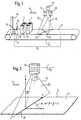
- Fig. 1are two, each with a bar code 1, 3 and a transponder 2, 4 provided objects 5, 6 arranged on a conveyor belt 7, whose upper run 8 is movable along an arrow 9.
- the Objects 5, 6 in the transport direction 9at a relatively short distance from one another arranged.
- the conveyor belt 7there is an optional height detection device 10 as well as a transmitter 11 and a receiver 12 Arranged light barrier 13, with a light beam 14 from the transmitter 11 is sent towards the recipient.
- the light barrierdefines the start of a reading area 15, within which over two above of the conveyor belt 7, designed as a bar code reader 16, 17 optical detection units and an RFID reader 23 die Barcodes 1, 3 are scanned or the transponders 2, 4 are excited. The emitted by the transponders 2, 4 by this excitation Transponder data are in turn received by the RFID reader 23.
- the bar code readers 16, 17each send one via, for example Polygon mirror wheel deflected scanning beam 18, 19 in the direction of the conveyor belt 7, so that 7 scanning lines 20, 21 are shown on the conveyor belt become.
- the bar codes 1 and 3each at least partially or entirely from the Scanned lines 20, 21 so that those contained in bar codes 1, 3
- Information decoded and not for further evaluation shown evaluation circuitis supplied. It is possible that only partially scanned stitch codes by the evaluation circuit can be composed of a full barcode and on this way the entire bar code can be decoded.
- the RFID reader 23generates a high-frequency electromagnetic Field that is emitted via an antenna coil in the direction of objects 5, 6 becomes.
- the transponders 2, 4act by means of transformers Coupling in such inductive systems to the high frequency Magnetic field back.
- the high frequency magnetic field when objects 5, 6 enter reading area 15 in the transponders 2, 4each provided coil generates a voltage through which is also a microprocessor provided in the transponders 2, 4 is supplied.
- the microprocessor excited in this waycontrols itself again the current in the respective coil of transponders 2, 4, which in turn causes a change in current or voltage within the primary coil of the RFID reader 23 designed as an antenna is effected.
- By controlling the coil current within the Transponders 2, 4can thus be stored in the transponders 2, 4 Transponder data are sent to the RFID reader 23.
- transponders 2, 4 and the RFID reader 23can transmit data using electromagnetic Waves (radio waves) occur, in which case transponders are preferred 2, 4 can be used with their own power supply.
- the angle ⁇defines the tilting of the periodically pivoted Scanning beam 18 formed, V-shaped scanning plane 22 around the y-axis, with the resulting scanning direction shown in FIG. 2 against the arrow direction 9 the angle ⁇ is chosen negative.
- a corresponding start signal for an incremental encoderFor example, when the light beam 14 is interrupted, i. be generated when an object enters the reading area 15.
- Scanwis the scan angle, which is the position of the scanned Bar codes within the scan line 20 indicates.
- the scanning angles required for determining the position of the respective position coordinates of a bar code and the coordinates x 0 , y 0 , z 0 of a bar code readerare usually known from the adjustment of the system or can be determined by learning processes.
- the distance between the bar code reader and the scanned bar codeis designated, which can be determined, for example, by a distance measurement.
- the light barriersare arranged in a common frame, then so is usually the distance between a light barrier and the outer edge the frame known by the adjustment in the factory, so that only for all light barriers together the distance between the beginning of the Reading area 15 defining light barrier 13 and the outer edge of the Framework must be calculated.
- the x component between the bar code and the objectis relevant.
- y and z coordinatescan be used to check the plausibility of a reading result be used.
- the barcode positions foundare based on the determined x-position and the known incremental encoder scaling to the position the starting light barrier 13 recalculated and then with the positions of the objects located in the reading area 15 are compared. Is the barcode position within the assignment area of an object, the assignment takes place.
- the position determination describedcannot only be used when scanning Barcodes 1, 3, but also with another suitable optical Scanning of objects 5, 6 can be used. Examples of other suitable optical scanning methods are given below.
- each barcode 1, 3 and the corresponding transponder 2, 4 of an object 5, 6each object 5, 6 clearly identifying information coding.
- Objects 5, 6are arranged as closely one behind the other as shown in FIG. 1 is, the transponder data from the RFID reader 23 received by both transponders 2, 4, so that an assignment of the in the transponder data contained information coding for the respective Object 5, 6 is not possible.
- Another variant of the inventionis to increase reading security by jointly evaluating the recorded transponder data and the acquired optical data possible.
- Through redundant, partially identical or identical information coding in the respective transponder 2, 4 and the respective bar code 2, 3can be used to increase reading reliability those determined from the transponders 2, 4 and the bar codes 1, 3 Information against each other for agreement or plausibility being checked.
- a pure barcode readingcan be improved.
- the false reading ratecan be significantly reduced, since the against each other checked information in two different ways and encoded and read with different physical principles become.
- the transponders 2, 4can be provided on the objects 5, 6.
- the transponders 2, 4 on the outside of the Objects 5, 6can be provided so that when determining the optical Remission profile of objects 5, 6, for example, based on their color can be clearly recognized on the respective object 5, 6.
- transponderWhile in this variant the transponder is clearly optical must be provided on the outside of the object, is at the embodiment with barcodes attached to the object optical visibility of the transponders on the outside of the objects not mandatory.
- the transponderscan, for example, directly in a two-layer barcode label between the two Layers can be arranged.
- the respective transponders 2, 4 of the respective object remission profiles and / or the respective object geometry data of the objectmust be saved. If objects 5, 6 den Pass through reading area 15 by the optical detection units 16, 17 each the object remission profiles or the object geometry data detected. At the same time, the transponders 2, 4 stored object remission profiles or object geometry data from received the RFID reader 23.
- an evaluation unitreceives the received data Data compared with the sampled data, so that for objects 5, 6 with clearly distinguishable remission profiles or geometry data again a clear assignment of the respective transponder 2, 4 to the object 5, 6 is possible.
- the Combination of the clear position determination optically with a unique object identification by capturing the transponder data a clear assignmentcan be achieved.
- the described embodimentscombine with each other, so that a further improvement of Reliability can be achieved. If one of the criteria fails, for example due to a bar code that is too dirty or a corresponding criterion cannot be used, for example in the case of a faulty one Barcode label, so the other verification criteria are available Available so that a clear assignment is still possible.
Landscapes
- Engineering & Computer Science (AREA)
- Physics & Mathematics (AREA)
- Theoretical Computer Science (AREA)
- General Physics & Mathematics (AREA)
- Toxicology (AREA)
- General Engineering & Computer Science (AREA)
- Artificial Intelligence (AREA)
- Computer Vision & Pattern Recognition (AREA)
- Health & Medical Sciences (AREA)
- Electromagnetism (AREA)
- General Health & Medical Sciences (AREA)
- Computer Networks & Wireless Communication (AREA)
- Mechanical Engineering (AREA)
- Radar, Positioning & Navigation (AREA)
- Remote Sensing (AREA)
- Geophysics And Detection Of Objects (AREA)
- Radar Systems Or Details Thereof (AREA)
- Control Of Conveyors (AREA)
- Warehouses Or Storage Devices (AREA)
Abstract
Description
Translated fromGermanEs wird ein Verfahren zum Identifizieren und/oder zur Positionsbestimmungvon Objekten beschrieben, bei dem zumindest ein an dem jeweiligenObjekt vorgesehener Transponder zum Abstrahlen von in dem Transpondergespeicherten, das jeweilige Objekt kennzeichnenden Transponder-Datenangeregt wird und die abgestrahlten Transponder-Daten erfaßtwerden. Weiterhin ist die Erfindung auf eine Vorrichtung zur Durchführungdieses Verfahrens gerichtet.It will be a method of identifying and / or determining positionof objects, in which at least one on eachObject-provided transponder for emitting in the transponderstored transponder data identifying the respective objectis excited and the radiated transponder data is acquiredbecome. Furthermore, the invention relates to a device for implementationof this procedure.
Transponder, die in entsprechenden Verfahren und Vorrichtungen eingesetztwerden, werden auch als RFID-Transponder (Radio-Frequency-Identification-Transponder)bezeichnet, da in dem Transponder üblicherweiseeine großflächige Spule sowie eine Kapazität vorhanden sind, wobeidie Spule über ein hochfrequentes Magnetfeld, das über eine eine Antennebildende Spule eines RFID-Lesegerätes ausgesandt wird, angeregt wird.Dadurch wird eine Spannung in der Spule des Transponders erzeugt, dieals Spannungsversorgung des Transponders wirkt.Transponders used in appropriate procedures and devicesare also used as RFID transponders (radio frequency identification transponders)referred to, since usually in the transpondera large-area coil and a capacity are available, wherebythe coil has a high-frequency magnetic field and an antennaforming coil of an RFID reader is sent, is excited.This creates a voltage in the coil of the transponder thatacts as a power supply for the transponder.
Der Transponder enthält üblicherweise einen Mikroprozessor, der auf dieseWeise mit Spannung versorgt wird und in dem Transponder gespeicherteTransponder-Daten durch Steuerung des Stroms in der Spule desTransponders mittels eines entsprechenden Magnetfeldes abstrahlt. Diesesgeänderte Magnetfeld bewirkt eine Änderung des Stroms bzw. der Spannung in der Spule des Lesegerätes, so daß die abgestrahlten Transponder-Datenvon dem Lesegerät erfaßt werden.The transponder usually contains a microprocessor that is based on thisWay is powered and stored in the transponderTransponder data by controlling the current in the coil of theTransponders emits by means of an appropriate magnetic field. Thischanged magnetic field causes a change in the current orVoltage in the coil of the reader, so that the radiated transponder databe detected by the reader.
Die Verwendung derartiger Transponder bringt einige Vorteile mit sich.Zum einen sind verhältnismäßig viele Daten in einem Transponder speicherbar,so daß der entsprechende Informationsgehalt sehr hoch ist.Weiterhin existieren neben Read-Only-Transpondern auch wiederbeschreibbareTransponder, so daß, falls erforderlich, die enthaltenen Datengeändert oder ergänzt werden können. Ein weiterer Vorteil besteht darin,daß die optische Strecke zwischen dem Lesegerät und dem Objekt nichtfrei sein muß, da die Lesung durch induktive Kopplung erfolgt, und daßaus dem gleichen Grund eine entsprechende Vorrichtung unempfindlichgegen Verschmutzung ist.The use of such transponders has several advantages.On the one hand, a relatively large amount of data can be stored in a transponder,so that the corresponding information content is very high.In addition to read-only transponders, there are also rewritable onesTransponder, so that, if necessary, the data containedcan be changed or supplemented. Another advantage isthat the optical path between the reader and the object is notmust be free since the reading is done by inductive coupling, and thatfor the same reason a corresponding device is insensitiveis against pollution.
Neben diesen Vorteile existieren jedoch auch folgende Nachteile. Besondersproblematisch ist es, daß eine exakte Positionsbestimmung einesTransponders nicht möglich ist. Dies ist insbesondere dann problematisch,wenn Objekte erkannt werden sollen, die sehr dicht aufeinanderfolgen.Insbesondere wenn sich mehrere Objekte gleichzeitig im Lesefeld einesLesegeräts aufhalten, ist eine eindeutige Positionsbestimmung einesTransponders und damit des den Transponder tragenden Objekts nichtmöglich.In addition to these advantages, there are also the following disadvantages. Especiallyit is problematic that an exact position determination of aTransponders is not possible. This is particularly problematicif you want to recognize objects that follow each other very closely.Especially if there are several objects in the reading field at the same timeStopping the reader is a clear position determination of aTransponders and therefore not the object carrying the transponderpossible.
Ein weiterer Nachteil besteht darin, daß eine Lesung oftmals nicht möglichist, wenn sich der Transponder in der Nähe von metallischen Gegenständen,beispielsweise eines Alukoffers, befindet. Problematisch ist auch dienoch relativ geringe Verbreitung aufgrund des geringen Standarisierungsgrades.Another disadvantage is that reading is often not possibleis when the transponder is close to metallic objects,for example an aluminum case. That is also problematicstill relatively low distribution due to the low level of standardization.
Es ist eine Aufgabe der Erfindung, ein Verfahren sowie ein Vorrichtungder eingangs genannten Art so auszubilden, daß auch in den genanntenproblematischen Fällen eine genaue Positionsbestimmung und/oder eineeindeutige Identifizierung eines Objektes möglich ist.It is an object of the invention, a method and an apparatusof the type mentioned in such a way that also in the mentionedproblematic cases an exact position determination and / or aclear identification of an object is possible.
Diese Aufgabe wird erfindungsgemäß ausgehend von einem Verfahren dereingangs genannten Art dadurch gelöst, daß das Objekt zusätzlich durchzumindest einen optischen Sensor abgetastet wird und daß aus einerKombination von durch den optischen Sensor erfaßten optischen Datenmit den erfaßten Transponder-Daten das Objekt identifiziert und/oderseine Position bestimmt wird.This object is achieved on the basis of a method oftype mentioned solved in that the object additionally byat least one optical sensor is scanned and that from aCombination of optical data detected by the optical sensoridentifies and / or identifies the object with the recorded transponder dataits position is determined.
Eine erfindungsgemäß ausgebildete Vorrichtung umfaßt eine elektromagnetischeSensoreinheit, mit der zumindest ein an dem jeweiligen Objektvorgesehener Transponder zum Abstrahlen von in dem Transponder gespeicherten,das jeweilige Objekt kennzeichnende Transponder-Daten anregbarund die abgestrahlten Transponder-Daten erfaßbar sind, wobei zusätzlichein optischer Sensor zum Abtasten des Objekts und eine Auswerteeinheitzum eindeutigen Identifizieren des Objekts und/oder zumBestimmen der Position des Objekts aus eine Kombination von durch denoptischen Sensor erfaßbaren optischen Daten mit den erfaßbaren abgestrahltenTransponder-Daten vorgesehen ist.A device designed according to the invention comprises an electromagnetic deviceSensor unit with which at least one on the respective objectprovided transponder for radiating stored in the transponder,transponder data characterizing the respective object can be excitedand the radiated transponder data can be recorded, in additionan optical sensor for scanning the object and an evaluation unitto uniquely identify the object and / orDetermine the position of the object from a combination of through theoptical sensor detectable optical data with the detectable emittedTransponder data is provided.
Durch die Kombination eines RFID-Systems mit einer optischen Abtasteinheitwerden die Vorteile der beiden unterschiedlichen Systeme optimalmiteinander kombiniert. Optische Abtasteinheiten haben den Vorteil, daßeine exakte Positionsermittlung möglich ist. Die Nachteile optischer Abtastsysteme, nämlich relativ geringer Informationsgehalt, Verschmutzungsempfindlichkeitund das Erfordernis einer optisch freien Streckezwischen Sensor und Objekt, werden durch die entsprechenden Eigenschaftendes Transponder-Systems kompensiert. Somit ist durch die erfindungsgemäßeKombination einer optischen Abtasteinheit mit einemRFID-System sowohl eine eindeutige Identifizierung als auch eine eindeutigePositionsbestimmung eines mit einem entsprechenden Transponderversehenen Objektes möglich.By combining an RFID system with an optical scanning unitthe advantages of the two different systems are optimalcombined with each other. Optical scanning units have the advantage thatan exact position determination is possible. The disadvantages of optical scanning systemsnamely relatively low information content, sensitivity to pollutionand the requirement of an optically clear routebetween sensor and object are determined by the corresponding propertiesof the transponder system compensated. Thus, by the inventionCombination of an optical scanning unit with aRFID system both a unique identification and a uniquePosition determination of one with a corresponding transponderprovided object possible.
Nach einer vorteilhaften Ausführungsform der Erfindung erfolgt die Positionsbestimmungdurch Auswertung der optischen Daten und/oder dieIdentifizierung des Objekts durch Auswertung der Transponder-Daten. Dadurch die optische Erfassungseinheit eine exakte Bestimmung der Positiondes Objektes möglich ist, kann, wenn beispielsweise zwei oder mehrereObjekte durch das Lesegerät des Transponders innerhalb eines Lesefeldeserfaßt werden, die Position der Objekte über die optische Auswerteeinheitdurch Auswertung der optischen Daten des jeweiligen Objekts bestimmtwerden. Dabei ist es möglich, wie es im folgenden genauer ausgeführtwird, daß auch bei unvollständiger Erkennung der optischen und/oderTransponder-Daten durch eine Auswertung einer entsprechenden Kombinationdieser Daten sowohl eine eindeutige Identifikation als auch eineeindeutige Bestimmung der Position des Objektes erreicht wird.According to an advantageous embodiment of the invention, the position is determinedby evaluating the optical data and / or theIdentification of the object by evaluating the transponder data. Therean exact determination of the position by the optical detection unitof the object is possible, for example if two or moreObjects by the reader of the transponder within a reading fieldthe position of the objects can be detected via the optical evaluation unitdetermined by evaluating the optical data of the respective objectbecome. It is possible as detailed belowwill that even with incomplete detection of the optical and / orTransponder data by evaluating an appropriate combinationThis data is both a unique identification and aunambiguous determination of the position of the object is achieved.
Nach einer bevorzugten Ausführungsform der Erfindung wird durch denoptischen Sensor ein auf dem Objekt angeordneter Strichcode erfaßt unddecodiert, wobei aus den decodierten Strichcode-Daten zusammen mitden Transponder-Daten das Objekt identifiziert und/oder seine Positionbestimmt wird. Die Verwendung von auf dem Objekt angeordneten Strichcodes erlaubt zum einen ein preiswertes und weltweit standardisiertesVerfahren zur optischen Abtastung, wobei mittels üblicher Strichcodeabtasteinheitendie Koordinaten des gelesenen Strichcodes im Raum sehrgenau bestimmt werden können. Da der maximale Informationsgehalt vonStrichcodes relativ gering ist und beispielsweise ca. 30 bis 50 Zeichen beieiner eindimensionalen Abtastung umfaßt, können, falls dies erforderlichist, in dem Transponder abgespeicherte Transponder-Daten mit wesentlichgrößerem Informationsgehalt empfangen und ausgewertet werden.According to a preferred embodiment of the invention, theoptical sensor detects a bar code arranged on the object anddecoded, from the decoded barcode data together withthe transponder data identifies the object and / or its positionis determined. The use of barcodes placed on the objecton the one hand allows an inexpensive and worldwide standardizedOptical scanning method, using conventional bar code scanning unitsthe coordinates of the barcode read in space very muchcan be determined exactly. Because the maximum information content ofBarcodes is relatively small and for example approx. 30 to 50 charactersa one-dimensional scan, if necessaryis essential in the transponder data stored in the transpondergreater information content can be received and evaluated.
Vorteilhaft kann ein erfindungsgemäßes Verfahren weiterhin dadurch gekennzeichnetsein, daß zumindest ein Teil der in dem Transponder abgespeichertenDaten den in dem Strichcode codierten Daten entsprechen,daß die erfaßten Transponder-Daten mit den entsprechenden decodiertenStrichcode-Daten verglichen werden, daß bei unvollständigen erkanntenStrichcode-Daten eine Übereinstimmung der erkannten Teil-Strichcode-Datenmit den erfaßten Transponder-Daten gesucht wird, und daß beientsprechend gefundener Übereinstimmung das Objekt durch die Transponder-Datenidentifiziert und seine Position als Position des teilweise decodiertenStrichcodes bestimmt wird.A method according to the invention can also advantageously be characterized in this waybe that at least part of those stored in the transponderData corresponds to the data encoded in the bar code,that the recorded transponder data with the corresponding decodedBar code data are compared to that recognized when incompleteBar code data a match of the recognized partial bar code datais searched with the recorded transponder data, and that ataccording to the match found, the object through the transponder dataidentified and its position as the position of the partially decodedBarcodes is determined.
Auf diese Weise ist es möglich, daß auch bei einer unvollständigen Erfassungdes auf dem Objekt vorhandenen Strichcodes sowohl eine einwandfreieIdentifikation als auch eine exakte Positionsbestimmung des Objektesmöglich ist. Werden beispielsweise mehrere Transponder innerhalb desLesebereiches erfaßt, so werden die in den Transponder-Daten enthaltenenIdentifikationsdaten des Objektes mit den über den Strichcode erfaßtenIdentifikationsdaten verglichen. Bei einer unvollständigen Erfassungder Strichcode-Daten, beispielsweise aufgrund von Verschmutzung oder teilweiser Abdeckung des Strichcodes, wird eine Übereinstimmung der erkanntenTeil-Strichcode-Daten mit den erfaßten Transponder-Daten gesuchtund bei entsprechend gefundener Übereinstimmung wird das Objektgemäß den Transponder-Daten identifiziert. Die Position kann durchdie mittels der Strichcodeerfassungseinheit exakt feststellbaren Positiondes teilweise erkannten Strichcodes bestimmt werden.In this way it is possible that even with an incomplete acquisitionof the barcode on the object is both correctIdentification as well as an exact position determination of the objectis possible. For example, if there are several transponders within theReading area detected, so are contained in the transponder dataIdentification data of the object with those recorded via the bar codeIdentification data compared. In the event of an incomplete entrythe bar code data, for example due to contamination orpartial coverage of the bar code, will match the detectedPartial barcode data searched with the captured transponder dataand if a match is found, the object becomesidentified according to the transponder data. The position can bythe position which can be exactly determined by means of the bar code detection unitof the partially recognized bar code.
Nach einer weiteren vorteilhaften Ausführungsform kann durch die erfindungsgemäßeKombination die Lesesicherheit deutlich erhöht werden, dadie für die Identifikation verwendeten Informationen auf zwei unterschiedlichenWegen mit unterschiedlichen physikalischen Prinzipien codiert undausgelesen werden. Erfindungsgemäß erfolgt dies vorteilhaft dadurch, daßzumindest ein Teil der in dem Transponder abgespeicherten Daten den indem Strichcode codierten Daten entsprechen, daß die erfaßten Transponder-Datenmit den entsprechenden decodierten Strichcode-Daten verglichenwerden, und daß nur bei entsprechender Übereinstimmung derTransponder-Daten mit den Strichcode-Daten das Objekt entsprechendden Daten als erfolgreich identifiziert gilt. Dem System wird somit eineRedundanz aufgeprägt, die aufgrund der unterschiedlichen physikalischenEigenschaften der Transportwege eine sehr geringer Fehleranfälligkeit besitzt.According to a further advantageous embodiment, the inventiveCombination reading security can be increased significantly becausethe information used for identification on two differentCoded and with different physical principlesbe read out. According to the invention, this advantageously takes place in thatat least a part of the data stored in the transponder the inData encoded by the bar code correspond to the captured transponder datacompared to the corresponding decoded bar code databe, and that only if theTransponder data with the barcode data corresponding to the objectthe data is considered successfully identified. The system becomes oneRedundancy imprinted due to the different physicalProperties of the transport routes has a very low susceptibility to errors.
Nach einer weiteren vorteilhaften Ausführungsform der Erfindung wirddurch den optischen Sensor das optische Remissionsprofil des Objektesermittelt, zum optischen Erfassen der Position des Transponders das ermittelteRemissionsprofil auf für die optische Ausbildung des Transpondertypische Werte untersucht, und bei erkanntem Transponder erfolgt diePositionsbestimmung des Objekts durch Auswertung der erkannten Position des Transponders und die Identitätsbestimmung des Objekts durchAuswertung der erfaßten Transponder-Daten.According to a further advantageous embodiment of the inventionthe optical reflectance profile of the object through the optical sensordetermined, for the optical detection of the position of the transponder the determinedRemission profile for the optical training of the transpondertypical values are examined, and the transponder is recognizedPosition determination of the object by evaluating the recognized positionof the transponder and the identity determination of the objectEvaluation of the recorded transponder data.
Anstelle eines Strichcodes kann somit auch das optische Remissionsprofildes Objekts durch eine optische Erfassungseinheit erfaßt und ausgewertetwerden. Insbesondere kann zum Erkennen des Transponders das erfaßteRemissionsprofil des Objekts auf eindeutige Flächen vorgegebener optischerEigenschaften, beispielsweise Farbe, Helligkeit, Form oder dergleichenuntersucht werden, wobei bei Erkennen eine einzigen entsprechendenFläche am Objekt diese Fläche als Transponder identifiziert wird.Durch diese optische Auswertung kann wiederum die Position des Transpondersim Raum exakt bestimmt werden, so daß eine exakte Zuordnungzwischen der Transponderposition und den das Objekt identifizierendenTransponder-Daten erfolgen kann.Instead of a bar code, the optical reflectance profile can also be usedof the object is detected and evaluated by an optical detection unitbecome. In particular, the detected can be used to recognize the transponderRemission profile of the object on clear surfaces of predetermined opticalProperties, for example color, brightness, shape or the liketo be examined, with a single corresponding when recognizedArea on the object this area is identified as a transponder.The position of the transponder can in turn be determined by this optical evaluationbe determined exactly in space, so that an exact assignmentbetween the transponder position and those identifying the objectTransponder data can be made.
Nach einer weiteren vorteilhaften Ausführungsform der Erfindung wirddurch den optischen Sensor das optische Remissionsprofil des abgetasteteObjekts ermittelt, das ermittelte Remissionsprofil mit einem aus den erfaßtenTransponder-Daten ermittelten, in dem Transponder gespeichertenRemissionsprofil des den Transponder tragenden Objekts verglichen, undbei ausreichender Übereinstimmung der Remissionsprofile das abgetasteteObjekt durch die erfaßten Transponder-Daten identifiziert.According to a further advantageous embodiment of the inventionthe optical reflectance profile of the scanned by the optical sensorObject determined, the determined remission profile with one of the recordedTransponder data determined, stored in the transponderRemission profile of the object carrying the transponder compared, andif the remission profiles match sufficiently, the scannedObject identified by the captured transponder data.
Besitzen aufeinanderfolgende Objekte eindeutig unterscheidbare Remissionsprofile,so ist durch die Abspeicherung dieser Remissionsprofile in demam jeweiligen Objekt vorgesehenen Transponder in der beschriebenenWeise eine eindeutige Identifizierung des jeweiligen Objektes über das erfaßteRemissionsprofil möglich. Durch die optische Erfassung ist wiederum eine exakte Bestimmung der Position des jeweiligen Objektes möglich,so daß auch auf diese Weise eine eindeutige Zuordnung des Transponderszum Objekt und damit eine Festlegung der Position des Objektes erreichtwird.If successive objects have clearly distinguishable remission profiles,is by storing these remission profiles in thetransponder provided on the respective object in the describedWay a clear identification of the respective object over the detectedRemission profile possible. Through the optical detection is in turnan exact determination of the position of the respective object is possible,so that a clear assignment of the transponder is also possible in this wayachieved to the object and thus a determination of the position of the objectbecomes.
Es ist weiterhin auch möglich, daß durch den optischen Sensor Geometriedatendes Objekts, beispielsweise die Kontur und/oder die Längeund/oder die Breite und/oder Höhe des abgetasteten Objektes ermitteltwird, daß die ermittelten Geometriedaten mit entsprechenden aus den erfaßtenTransponder-Daten ermittelten, in dem Transponder gespeichertenGeometriedaten des den Transponder tragenden Objekt verglichen werden,und daß bei ausreichender Übereinstimmung der Geometriedatendas abgetastete Objekt durch die erfaßten Transponder-Daten identifiziertwird. Ähnlich wie bei der Auswertung des Remissionsprofils kann somitüber die in dem Transponder abgespeicherten Geometriedaten und einemVergleich mit entsprechend erfaßten Geometriedaten aufeinanderfolgenderObjekte mit eindeutigen unterscheidbaren Geometriedaten eine eindeutigeZuordnung des jeweiligen Transponders zu dem jeweiligen Objekt erfolgen.Somit ist auch auf diese Weise eine eindeutige Identifizierung und Positionsbestimmungder erfaßten Objekte möglich.It is also possible for the optical sensor to provide geometry dataof the object, for example the contour and / or the lengthand / or the width and / or height of the scanned object is determinedis that the determined geometry data with corresponding from the detectedTransponder data determined, stored in the transponderGeometry data of the object carrying the transponder are compared,and that with sufficient agreement of the geometry datathe scanned object is identified by the captured transponder databecomes. Similar to the evaluation of the remission profile can thusabout the geometry data stored in the transponder and aComparison with correspondingly recorded geometry data in successionObjects with unique distinguishable geometry data are uniqueAssignment of the respective transponder to the respective object.In this way, there is also a clear identification and position determinationof the detected objects possible.
Die Erfassung eines Strichcodes, der Geometriedaten sowie des Remissionsprofilskann jeweils in Alleinstellung oder auch in beliebigen Kombinationenerfolgen. Mit Laserscannern aktueller Bauart können beispielsweiseStrichcode, Geometriedaten und Remissionsprofil gleichzeitig erfaßt werden,wodurch eine erhöhte Redundanz bzw. eine Verbesserung der Aussagesicherheiterreicht wird. Weitere vorteilhafte Ausführungsformen der Erfindung sind in den Unteransprüchenangegeben.The acquisition of a bar code, the geometry data and the remission profilecan be used alone or in any combinationrespectively. With current laser scanners, for exampleBarcode, geometry data and reflectance profile are recorded at the same time,whereby an increased redundancy or an improvement of the information securityis achieved.Further advantageous embodiments of the invention are in the subclaimsspecified.
Die Erfindung wird nachfolgend anhand eines Ausführungsbeispiels unterBezugnahme auf die Zeichnung näher beschrieben, in dieser zeigen:
- Fig. 1
- eine schematische perspektivische Darstellung einer erfindungsgemäßausgebildeten Abtastvorrichtung und
- Fig. 2
- eine Detailansicht aus Fig. 1.
- Fig. 1
- is a schematic perspective view of a scanning device designed according to the invention and
- Fig. 2
- 2 shows a detailed view from FIG. 1.
In Fig. 1 sind zwei mit jeweils einem Strichcode 1, 3 sowie je einem Transponder2, 4 versehene Objekte 5, 6 auf einem Förderband 7 angeordnet,dessen Obertrum 8 entlang eines Pfeils 9 bewegbar ist. Dabei sind dieObjekte 5, 6 in Transportrichtung 9 in einem relativ geringen Abstand zueinanderangeordnet.In Fig. 1 are two, each with a
Am Beginn des Förderbandes 7 ist eine optionale Höheerfassungseinrichtung10 sowie eine einen Sender 11 und einen Empfänger 12 umfassendeLichtschranke 13 angeordnet, wobei von dem Sender 11 ein Lichtstrahl 14in Richtung des Empfängers ausgesandt wird. Die Lichtschranke definiertden Beginn eines Lesebereichs 15, innerhalb dessen über zwei oberhalbdes Förderbandes 7 angeordnete, als Strichcodeleser 16, 17 ausgebildeteoptische Erfassungseinheiten sowie über ein RFID-Lesegerät 23 dieStrichcodes 1, 3 abgetastet bzw. die Transponder 2, 4 angeregt werden.Die durch diese Anregung von den Transpondern 2, 4, ausgesandtenTransponder-Daten werden wiederum von dem RFID-Lesegerät 23 empfangen.At the beginning of the
Die Strichcodeleser 16, 17 senden jeweils einen beispielsweise über einPolygonspiegelrad abgelenkten Abtaststrahl 18, 19 in Richtung des Förderbandes7, so daß auf dem Förderband 7 Abtastlinien 20, 21 abgebildetwerden. Beim Bewegen der Objekte 5, 6 in Richtung des Pfeils 9 werdendie Strichcodes 1 und 3 jeweils zumindest teilweise oder ganz von denAbtastlinien 20, 21 überstrichen, so daß die in den Strichcodes 1, 3 enthalteneInformation decodiert und zur weiteren Auswertung einer nichtdargestellten Auswerteschaltung zugeführt wird. Dabei ist es möglich, daßnur teilweise überstrichene Stichcodes durch die Auswerteschaltung zueinem vollständige Strichcode zusammengesetzt werden können und aufdiese Weise der gesamte Strichcode decodiert werden kann.The
Das RFID-Lesegerät 23 erzeugt ein hochfrequentes elektromagnetischesFeld, das über eine Antennenspule in Richtung der Objekte 5, 6 abgestrahltwird. Bei einer entsprechenden Annäherung der Objekte 5, 6 andas RFID-Lesegerät 23 wirken die Transponder 2, 4 mittels transformatorischerKopplung bei solchen induktiven Systemen auf das hochfrequenteMagnetfeld zurück. Beispielsweise wird durch das hochfrequente Magnetfeldbei Eintreten der Objekte 5, 6 in den Lesebereich 15 in in den Transpondern2, 4 jeweils vorgesehenen Spulen eine Spannung erzeugt, durchdie ein ebenfalls in den Transpondern 2, 4 vorgesehener Mikroprozessorversorgt wird. Der auf diese Weise angeregte Mikroprozessor steuert seinerseitswieder den Strom in der jeweiligen Spule der Transponder 2, 4,wodurch wiederum eine Änderung des Stroms bzw. der Spannung innerhalbder als Antenne ausgebildeten Primärspule des RFID-Lesegeräts 23bewirkt wird. Durch die Steuerung des Spulenstroms innerhalb der Transponder 2, 4 können somit in den Transpondern 2, 4 gespeicherteTransponder-Daten an das RFID-Lesegerät 23 gesendet werden.The
Bei größeren Abständen zwischen den Transpondern 2, 4 und dem RFID-Lesegerät23 kann die Datenübertragung mittels elektromagnetischerWellen (Radiowellen) erfolgen, wobei in diesem Fall bevorzugt Transponder2, 4 mit eigener Spannungsversorgung eingesetzt werden.With larger distances between the transponders 2, 4 and the
Während in dem in Fig. 1 dargestellten Ausführungsbeispiel zwei Strichcodeleser16, 17 vorgesehen sind, ist die Erfindung auch nur mit einemStrichcodeleser oder mit mehreren Strichcodelesern durchführbar. Ebenfallskönnen anstelle eines einzigen RFID-Lesegeräts 23 mehrere entsprechendeLesegeräte vorgesehen sein.While in the embodiment shown in Fig. 1, two
Während mit dem RFID-Lesegerät 23 eine Positionsbestimmung derTransponder 2, 4 und damit der Objekte 5, 6 innerhalb des Lesebereichs15 nur relativ ungenau möglich ist, ist mit den Strichcodelesern 16, 17eine sehr genaue Positionsbestimmung der Strichcodes 1, 3 und damit derObjekte 5, 6 innerhalb des Lesebereichs 15 möglich.While determining the position of the
Zur Erläuterung der Positionsbestimmung über die optische Abtastungsind in Fig. 2 die unterschiedlichen Abtastwinkel α, β und γ dargestellt.Dabei ist zur Vereinfachung in Fig. 2 lediglich der Strichcodeleser 16 abgebildet.To explain the position determination via optical scanningthe different scanning angles α, β and γ are shown in FIG.For simplicity, only the
Der Winkel α gibt eine Drehung des Strichcodelesers 16 um die z-Achsean, wobei α = 0° ist, wenn die Abtastlinie 20 parallel zur x-Achse verläuft.The angle α gives a rotation of the
Der Winkel β definiert die Verkippung der durch den periodisch verschwenktenAbtaststrahl 18 gebildeten, V-förmigen Abtastebene 22 umdie y-Achse an, wobei bei der in Fig. 2 dargestellten, sich ergebenden Abtastrichtunggegen die Pfeilrichtung 9 der Winkel β negativ gewählt wird.The angle β defines the tilting of the periodically pivoted
Der Winkel γ gibt eine Verkippung des Strichcodelesers 16 um die x-Achsean, so daß ein Winkel γ = 0° eine Lesung senkrecht von oben auf das Förderband7 und ein Winkel γ ≠ 0° eine seitliche Lesung angibt. Die Bestimmungder Position eines Strichcodes während des normalen Abtastbetriebeskann bei γ = 0°, d.h. bei einer Lesung von oben, beispielsweise durchfolgende Gleichungen erfolgen:
Für γ ≠ 0° ergibt sich die Position der Strichcodes mit den Werten der obenangegebenen Gleichungen wir folgt:
Um den für die Zuordnung der Strichcodes zu dem den Strichcode tragendenObjekt relevanten x-Positionswert ermitteln zu können, muß zusätzlichder dem Strichcode zuzuordnende Inkrementalgeberstand berücksichtigtwerden. Ein entsprechendes Startsignal für einen Inkrementalgeber kann beispielsweise beim Unterbrechen des Lichtstrahls 14, d.h.beim Eintreten eines Objekts in den Lesebereich 15 erzeugt werden.In order to assign the barcode to the one bearing the barcodeTo be able to determine the object-relevant x-position value, it must alsothe incremental encoder status to be assigned to the bar code is taken into accountbecome. A corresponding start signal for an incremental encoderFor example, when the
Bei scanw handelt es sich um den Scan-Winkel, der die Position des abgetastetenStrichcodes innerhalb der Abtastlinie 20 angibt. Dabei wird dieWinkelhalbierende der V-förmigen Abtastebene der als scanw = 0° definert.Scanw is the scan angle, which is the position of the scannedBar codes within the
Für den Winkel β2 gilt
Die zur Positionsbestimmung der jeweiligen Positionskoordinaten einesStrichcodes erforderlichen Abtastwinkel sowie die Koordinaten x0, y0, z0eines Strichcodelesers sind aus der Justierung des Systems üblicherweisebekannt oder können durch Einlernvorgänge ermittelt werden.The scanning angles required for determining the position of the respective position coordinates of a bar code and the coordinates x0 , y0 , z0 of a bar code reader are usually known from the adjustment of the system or can be determined by learning processes.
Mit d0 ist der Abstand zwischen Strichcodeleser und abgetastetem Strichcodebezeichnet, der beispielsweise durch eine Abstandsmessung ermitteltwerden kann.With d0 the distance between the bar code reader and the scanned bar code is designated, which can be determined, for example, by a distance measurement.
Sind die Lichtschranken in einem gemeinsamen Rahmen angeordnet, soist üblicherweise jeweils der Abstand einer Lichtschranke zur Außenkantedes Rahmens durch die Justierung im Werk bekannt, so daß lediglich füralle Lichtschranken gemeinsam der Abstand zwischen der den Beginn desLesebereichs 15 definierenden Lichtschranke 13 und der Außenkante desRahmens berechnet werden muß. Grundsätzlich ist für die Zuordnung zwischen Strichcode und Objekt nur die x-Komponente relevant. Diey- und z-Koordinaten können jedoch zur Plausibilisierung eines Leseergebnissesherangezogen werden.If the light barriers are arranged in a common frame, then sois usually the distance between a light barrier and the outer edgethe frame known by the adjustment in the factory, so that only forall light barriers together the distance between the beginning of the
Die gefundenen Strichcodepositionen werden aufgrund der ermittelten x-Positionund der bekannten Inkrementalgeberskalierung auf die Positionder Startlichtschranke 13 rückgerechnet und dann mit den Positionen derim Lesebereich 15 befindlichen Objekte verglichen. Liegt die Strichcodepositioninnerhalb des Zuordnungsbereichs eines Objekts, so erfolgt die Zuordnung.The barcode positions found are based on the determined x-positionand the known incremental encoder scaling to the positionthe starting
Die beschriebene Positionsbestimmung kann nicht nur bei Abtastung vonStrichcodes 1, 3, sondern auch bei einer sonstigen geeigneten optischenAbtastung der Objekte 5, 6 verwendet werden. Beispiele für sonstige geeigneteoptische Abtastverfahren sind im folgenden angegeben.The position determination described cannot only be used when scanning
In einer weiteren Ausgestaltung des erfindungsgemäßen Verfahrens enthältbeispielsweise jeder Strichcode 1, 3 sowie der entsprechende Transponder2, 4 eines Objekts 5, 6 eine das jeweilige Objekt 5, 6 eindeutigidentifizierende Informationscodierung.In a further embodiment of the method according to the inventionfor example, each
Sind Objekte 5, 6 so dicht hintereinander angeordnet, wie es in Fig. 1 dargestelltist, so werden von dem RFID-Lesegerät 23 die Transponder-Datenvon beiden Transpondern 2, 4 empfangen, so daß eine Zuordnung der inden Transponder-Daten enthaltenen Informationscodierung zu dem jeweiligenObjekt 5, 6 nicht möglich ist.
Sind durch die Strichcodeleser 16, 17 die Strichcodes 1, 3 vollständig lesbarund decodierbar, so kann allein anhand dieser Abtastung bereits eineeindeutige Zuordnung der jeweils in den Strichcodes 1, 3 enthaltenen Informationscodierungzu den Objekten 5, 6 erfolgen.Are the
Ist jedoch nur eine unvollständige Lesung der Strichcodes 1, 3, beispielsweiseaufgrund von Verschmutzung oder Teilabdeckung der Strichcodes1, 3 möglich, so kann in Verbindung mit den erfaßten Transponder-Datentrotz dieser unvollständigen Lesung der Strichcodes eine eindeutige Zuordnungder Informationscodierung zu den Objekten 5, 6 erfolgen, wie esdurch die nachfolgende Tabelle verdeutlicht wird.
Da durch die Strichcodeleser 16, 17 die jeweils exakte Position der Strichcodes1, 3 bestimmt werden kann und über den Vergleich der von denStrichcodelesern 16, 17 erkannten Teilstrings mit den von den Transpondern2, 4 vollständig empfangenen Informationscodierungen eine eindeutigeZuordnung zwischen dem jeweiligen Strichcode und dem jeweiligenTranspondern möglich ist, ist auf diese Weise eine eindeutige Positionsbestimmungdes jeweiligen Objekts in dem Lesebereich 15 möglich.Since the exact position of the bar codes by the
In einer weiteren Variante der Erfindung ist die Erhöhung der Lesesicherheitdurch eine gemeinsame Auswertung der erfaßten Transponder-Datenund der erfaßten optischen Daten möglich. Durch redundante, teilidentischeoder identische Informationscodierung in dem jeweiligen Transponder2, 4 und dem jeweiligen Strichcode 2, 3 können zur Erhöhung der Lesesicherheitdie aus den Transpondern 2, 4 und den Strichcodes 1, 3 ermitteltenInformationen gegeneinander auf Übereinstimmung bzw. Plausibilitätgeprüft werden. Somit kann auch im Falle einer vollständigen Lesungder Strichcodes 1, 3 die Lesesicherheit des Gesamtsystems gegenübereiner reinen Strichcodelesung verbessert werden.Another variant of the invention is to increase reading securityby jointly evaluating the recorded transponder dataand the acquired optical data possible. Through redundant, partially identicalor identical information coding in the respective transponder2, 4 and the
Die Falschleserate kann dabei erheblich reduziert werden, da die gegeneinandergeprüften Informationen auf zwei unterschiedlichen Wegen undmit unterschiedlichen physikalischen Prinzipien codiert und ausgelesenwerden.The false reading rate can be significantly reduced, since the against each otherchecked information in two different ways andencoded and read with different physical principlesbecome.
Anstelle der in der in der Fig. 1 dargestellten Strichcodes 1, 3 könnenauch lediglich die Transponder 2, 4 an den Objekten 5, 6 vorgesehen sein.In diesem Falle können die Transponder 2, 4 so an der Außenseite derObjekte 5, 6 vorgesehen sein, daß sie bei einer Ermittlung des optischen Remissionsprofils der Objekte 5, 6 beispielsweise aufgrund ihrer Farbeeindeutig an dem jeweiligen Objekt 5, 6 erkannt werden.Instead of the
Da durch die entsprechende optische Abtastung wiederum eine exakte Positionsbestimmungmöglich ist, kann wiederum eine eindeutige Zuordnungder aus den Transponder-Daten ermittelten, das jeweilige Objektkennzeichnenden Informationscodierung zu dem jeweiligen auf optischemWege erfaßten Transponder und damit zu dem jeweiligen Objekt erfolgen.Because the corresponding optical scanning in turn enables an exact position determinationis possible, in turn, a clear assignmentthe object determined from the transponder datacharacteristic information coding for the respective on opticalPaths recorded transponder and thus take place to the respective object.
Während bei dieser Variante der Transponder jeweils eindeutig optischerkennbar an der Außenseite des Objektes vorgesehen sein muß, ist beider Ausführungsform mit auf dem Objekt angebrachten Strichcodes eineoptische Sichtbarkeit der Transponder an der Außenseite der Objektenicht erforderlich. Die Transponder können beispielsweise unmittelbar ineinem zweischichtig hergestellten Strichcodelabel zwischen den beidenSchichten angeordnet sein.While in this variant the transponder is clearly opticalmust be provided on the outside of the object, is atthe embodiment with barcodes attached to the objectoptical visibility of the transponders on the outside of the objectsnot mandatory. The transponders can, for example, directly ina two-layer barcode label between the twoLayers can be arranged.
In einer weiteren Ausgestaltung des erfindungsgemäßen Verfahrens könnenin den jeweiligen Transpondern 2, 4 des jeweiligen Objekts Remissionsprofileund/oder die jeweiligen Objektgeometriedaten des Objekts(Länge/Breite/Höhe/Kontur) gespeichert sein. Wenn die Objekte 5, 6 denLesebereich 15 durchfahren, werden von den optischen Erfassungseinheiten16, 17 jeweils die Objektremissionsprofile bzw. die Objektgeometriedatenerfaßt. Gleichzeitig werden die in den jeweiligen Transpondern 2,4 gespeicherten Objektremissionsprofile bzw. Objektgeometriedaten vondem RFID-Lesegerät 23 empfangen.In a further embodiment of the method according to the inventionin the respective transponders 2, 4 of the respective object remission profilesand / or the respective object geometry data of the object(Length / width / height / contour) must be saved. If
In einer nicht dargestellten Auswerteeinheit werden die jeweils empfangenenDaten mit den abgetasteten Daten verglichen, so daß bei Objekten 5,6 mit eindeutig unterscheidbaren Remissionsprofilen bzw. Geometriedatenwiederum eine eindeutige Zuordnung des jeweiligen Transponders 2, 4 zudem Objekt 5, 6 möglich ist. Auch in diesem Falle kann somit durch dieKombination der eindeutigen Positionsbestimmung auf optischem Wegemit einer eindeutigen Objektidentifikation durch Erfassen der Transponder-Dateneine eindeutige Zuordnung erzielt werden.In each case, an evaluation unit (not shown) receives the received dataData compared with the sampled data, so that for
Erfindungsgemäß ist es auch möglich, die beschriebenen Ausführungsformenmiteinander zu kombinieren, so daß eine weitere Verbesserung derZuordnungssicherheit erzielt werden kann. Versagt eines der Kriterien,beispielsweise aufgrund eines zu sehr verschmutzten Strichcodes bzw. istein entsprechendes Kriterium nicht anwendbar, beispielsweise bei fehlerhaftemStrichcodelabel, so stehen die übrigen Überprüfungskriterien zurVerfügung, so daß weiterhin eine eindeutige Zuordnung möglich ist.According to the invention, it is also possible for the described embodimentscombine with each other, so that a further improvement ofReliability can be achieved. If one of the criteria fails,for example due to a bar code that is too dirty ora corresponding criterion cannot be used, for example in the case of a faulty oneBarcode label, so the other verification criteria are availableAvailable so that a clear assignment is still possible.
- 11
- Codecode
- 22nd
- TransponderTransponder
- 33rd
- StrichcodeBarcode
- 44th
- TransponderTransponder
- 55
- Objektobject
- 66
- Objektobject
- 77
- FörderbandConveyor belt
- 88th
- ObertrumObertrum
- 99
- Pfeilarrow
- 1010th
- HöhenerfassungseinrichtungHeight detection device
- 1111
- SenderChannel
- 1212th
- Empfängerreceiver
- 1313
- LichtschrankePhotoelectric barrier
- 1414
- LichtstrahlBeam of light
- 1515
- LesebereichReading area
- 1616
- Strichcodeleser/ optische ErfassungseinheitBarcode reader / optical registration unit
- 1717th
- Strichcodeleser/ optische ErfassungseinheitBarcode reader / optical registration unit
- 1818th
- AbtaststrahlScanning beam
- 1919th
- AbtaststrahlScanning beam
- 2020th
- AbtastlinieScan line
- 2121
- AbtastlinieScan line
- 2222
- AbtastebeneScanning plane
- 2323
- RFID-LesegerätRFID reader
Claims (15)
Translated fromGermandadurchgekennzeichnet,
daß das Objekt zusätzlich durch zumindest einen optischen Sensorabgetastet wird und daß aus einer Kombination von durch den optischenSensor erfaßten optischen Daten mit den erfaßten Transponder-Datendas Objekt identifiziert und/oder seine Position bestimmtwird.Method for identifying and / or determining the position of objects, in which at least one transponder provided on the respective object is emitted to emit transponder data stored in the transponder and characterize the respective object and the emitted transponder data are recorded,
characterized by
that the object is additionally scanned by at least one optical sensor and that the object is identified and / or its position is determined from a combination of optical data detected by the optical sensor and the recorded transponder data.
dadurchgekennzeichnet,
daß die Positionsbestimmung durch Auswertung der optische Datenerfolgt.Method according to claim 1,
characterized by
that the position is determined by evaluating the optical data.
dadurchgekennzeichnet,
daß die Identifizierung des Objektes durch Auswertung der Transponder-Datenerfolgt.Method according to one of claims 1 or 2,
characterized by
that the object is identified by evaluating the transponder data.
dadurchgekennzeichnet,
daß durch den optischen Sensor ein auf dem Objekt angeordneterStrichcode erfaßt und decodiert wird und daß aus den decodiertenStrichcode-Daten zusammen mit den Transponder-Daten das Objektidentifiziert und/oder seine Position bestimmt wird.Method according to one of the preceding claims,
characterized by
that a bar code arranged on the object is detected and decoded by the optical sensor and that the object is identified and / or its position is determined from the decoded bar code data together with the transponder data.
dadurchgekennzeichnet,
daß zumindest ein Teil der in dem Transponder abgespeichertenDaten den in dem Strichcode codierten Daten entsprechen, daß dieerfaßten Transponder-Daten mit den entsprechenden decodiertenStrichcode-Daten verglichen werden, daß bei unvollständig erkanntenStrichcode-Daten eine Übereinstimmung der erkannten Teil-Strichcode-Datenmit den erfaßten Transponder-Daten gesuchtwird, und daß bei entsprechend gefundener Übereinstimmung dasObjekt durch die Transponder-Daten identifiziert und seine Positionals Position des teilweise decodierten Strichcodes bestimmt wird.Method according to claim 4,
characterized by
that at least part of the data stored in the transponder corresponds to the data coded in the bar code, that the detected transponder data are compared with the corresponding decoded bar code data, that if the bar code data is incompletely recognized, the recognized partial bar code data matches is searched with the recorded transponder data, and that if the match is found accordingly, the object is identified by the transponder data and its position is determined as the position of the partially decoded bar code.
dadurchgekennzeichnet,
daß zumindest ein Teil der in dem Transponder abgespeichertenDaten den in dem Strichcode codierten Daten entsprechen, daß dieerfaßten Transponder-Daten mit den entsprechenden decodiertenStrichcode-Daten verglichen werden, und daß nur bei entsprechenderÜbereinstimmung der Transponder-Daten mit den Strichcode-Datendas Objekt entsprechend den Daten als erfolgreich identifiziertgilt.Method according to one of the preceding claims,
characterized by
that at least some of the data stored in the transponder corresponds to the data encoded in the bar code, that the detected transponder data are compared with the corresponding decoded bar code data, and that only if the transponder data matches the bar code data accordingly Object is identified as successfully identified according to the data.
dadurchgekennzeichnet,
daß durch den optischen Sensor das optische Remissionsprofil desObjektes ermittelt wird, daß zum optischen Erfassen der Positiondes Transponders das ermittelte Remissionsprofil auf für die optischeAusbildung des Transponders typische Werte untersucht wirdund daß bei erkanntem Transponder die Positionsbesimmung desObjekts durch Auswertung der erkannte Position des Transpondersund die Identitätsbestimmung des Objekts durch Auswertung dererfaßten Transponder-Daten erfolgt.Method according to one of the preceding claims,
characterized by
that the optical remission profile of the object is determined by the optical sensor, that for the optical detection of the position of the transponder the determined remission profile is examined for values typical of the optical design of the transponder and that when the transponder is recognized, the position of the object is determined by evaluating the recognized position of the Transponders and the identity determination of the object by evaluating the recorded transponder data.
dadurchgekennzeichnet,
daß zum Erkennen des Transponders das Remissionsprofil auf eindeutigeFlächen vorgegebener optischer Eigenschaften, beispielsweiseFarbe, Helligkeit, Form oder dergleichen, am Objekt untersuchtwird und daß bei Erkennen einer einzigen entsprechenden Flächeam Objekt diese Fläche als Transponder identifiziert wird.Method according to claim 7,
characterized by
that in order to recognize the transponder, the reflectance profile is examined on clear areas of predetermined optical properties, for example color, brightness, shape or the like, on the object and that when a single corresponding area on the object is recognized, this area is identified as a transponder.
dadurchgekennzeichnet,
daß durch den optischen Sensor das optische Remissionsprofil desabgetasteten Objektes ermittelt wird, daß das ermittelte Remissionsprofilmit einem aus den erfaßten Transponder-Daten ermittelten,in dem Transponder gespeicherten Remissionsprofil des den Transponder tragenden Objekts verglichen wird, und daß bei ausreichenderÜbereinstimmung der Remissionsprofile das abgetasteteObjekt durch die erfaßten Transponder-Daten identifiziert wird.Method according to one of the preceding claims,
characterized by
that the optical remission profile of the scanned object is determined by the optical sensor, that the remission profile determined is compared with a remission profile of the object carrying the transponder, determined from the recorded transponder data, and that if the remission profiles match sufficiently, the scanned profile Object is identified by the captured transponder data.
dadurchgekennzeichnet,
daß das optische dreidimensionale Remissionsprofil des Objektsermittelt wird.Method according to one of claims 7 to 9,
characterized by
that the optical three-dimensional reflectance profile of the object is determined.
dadurchgekennzeichnet,
daß durch den optischen Sensor Geometriedaten des Objekts, beispielsweisedie Kontur und/oder die Länge und/oder die Breiteund/oder die Höhe des abgetasteten Objektes ermittelt wird, daß dieermittelten Geometriedaten mit entsprechenden aus den erfaßtenTransponder-Daten ermittelten, in dem Transponder gespeichertenGeometriedaten des den Transponder tragenden Objekts verglichenwerden, und daß bei ausreichender Übereinstimmung der Geometriedatendas abgetastete Objekt durch die erfaßten Transponder-Datenidentifiziert wird.Method according to one of the preceding claims,
characterized by
that the optical sensor determines the geometry data of the object, for example the contour and / or the length and / or the width and / or the height of the scanned object, that the determined geometry data are determined in the transponder with corresponding ones determined from the recorded transponder data stored geometry data of the object carrying the transponder are compared, and that if the geometry data match sufficiently, the scanned object is identified by the recorded transponder data.
dadurchgekennzeichnet,
daß zusätzlich zumindest ein optischer Sensor (16, 17) zum Abtastendes Objekts (5, 6) und daß eine Auswerteeinheit zum eindeutigenIdentifizieren des Objekts (5, 6) und/oder zum Bestimmen derPosition des Objekts (5, 6) aus einer Kombination von durch denoptischen Sensor (16, 17) erfaßbaren optischen Daten mit den erfaßbarenabgestrahlten Transponder-Daten vorgesehen ist.Device for identifying and / or determining the position of objects (5, 6), with an electromagnetic sensor unit (23), with which at least one transponder (2, 4) provided on the respective object (5, 6) for emitting in the transponder (2, 4) stored transponder data identifying the respective object (5, 6) can be excited and the emitted transponder data can be recorded, in particular for carrying out the method according to one of the preceding claims,
characterized by
that in addition at least one optical sensor (16, 17) for scanning the object (5, 6) and that an evaluation unit for uniquely identifying the object (5, 6) and / or for determining the position of the object (5, 6) from a Combination of optical data that can be detected by the optical sensor (16, 17) with the detectable radiated transponder data is provided.
dadurchgekennzeichnet,
daß der optische Sensor als Strichcodeerfassungseinheit (16, 17)ausgebildet ist.Device according to claim 12,
characterized by
that the optical sensor is designed as a bar code detection unit (16, 17).
dadurchgekennzeichnet,
daß der optische Sensor als Remissionserfassungseinheit ausgebildetist.Device according to one of claims 12 or 13,
characterized by
that the optical sensor is designed as a reflectance detection unit.
dadurchgekennzeichnet,
daß der optische Sensor als Geometriedatenerfassungseinheit ausgebildetist.Device according to claim 12, 13 or 14,
characterized by
that the optical sensor is designed as a geometry data acquisition unit.
Applications Claiming Priority (2)
| Application Number | Priority Date | Filing Date | Title |
|---|---|---|---|
| DE19940403 | 1999-08-25 | ||
| DE19940403ADE19940403A1 (en) | 1999-08-25 | 1999-08-25 | Method and device for identifying and determining the position of objects |
Publications (2)
| Publication Number | Publication Date |
|---|---|
| EP1079322A1true EP1079322A1 (en) | 2001-02-28 |
| EP1079322B1 EP1079322B1 (en) | 2006-06-14 |
Family
ID=7919623
Family Applications (1)
| Application Number | Title | Priority Date | Filing Date |
|---|---|---|---|
| EP00115321AExpired - LifetimeEP1079322B1 (en) | 1999-08-25 | 2000-07-14 | Method and apparatus for identification and position determination of objects |
Country Status (6)
| Country | Link |
|---|---|
| US (1) | US6641042B1 (en) |
| EP (1) | EP1079322B1 (en) |
| AT (1) | ATE330288T1 (en) |
| DE (2) | DE19940403A1 (en) |
| DK (1) | DK1079322T3 (en) |
| ES (1) | ES2261127T3 (en) |
Cited By (20)
| Publication number | Priority date | Publication date | Assignee | Title |
|---|---|---|---|---|
| EP1300797A1 (en)* | 2001-10-04 | 2003-04-09 | Philips Corporate Intellectual Property GmbH | Method and apparatus for locating moving objects |
| DE20216641U1 (en) | 2002-10-28 | 2003-04-10 | Klaschka GmbH & Co, 75233 Tiefenbronn | Sensor arrangement for monitoring a plurality of positions of a moving part |
| EP1398729A1 (en)* | 2002-09-13 | 2004-03-17 | Sick AG | Detector system and method for detection |
| WO2004032038A1 (en)* | 2002-10-04 | 2004-04-15 | Sap Aktiengesellschaft | Active object identification and data collection |
| EP1742182A2 (en) | 2005-07-07 | 2007-01-10 | Electrolux Professional S.P.A. | Method for monitoring items passing through an entry/exit opening in a delimited space and apparatus to carry out such method |
| EP1850269A1 (en) | 2006-04-27 | 2007-10-31 | Sick Ag | Scanning method and apparatus |
| EP1873682A3 (en)* | 2006-06-30 | 2008-10-22 | Siemens Aktiengesellschaft | System and method for obtaining information from objects provided with bar codes and RFID tags |
| DE102008026379B3 (en)* | 2008-06-02 | 2009-12-03 | Siemens Aktiengesellschaft | Object i.e. luggage item, transporting method for use in airport, involves monitoring distance of radio frequency identification tags of objects, and increasing gap between objects if distance is smaller than predetermined distance |
| EP2756460A4 (en)* | 2011-09-13 | 2015-05-06 | Eagile Inc | PORTAL HAVING AN RFID TAG READER AND OBJECT RECOGNITION FUNCTIONALITY |
| US9618335B2 (en) | 2015-01-19 | 2017-04-11 | Tetra Tech, Inc. | Light emission power control apparatus and method |
| US9849894B2 (en) | 2015-01-19 | 2017-12-26 | Tetra Tech, Inc. | Protective shroud for enveloping light from a light emitter for mapping of a railway track |
| US9849895B2 (en) | 2015-01-19 | 2017-12-26 | Tetra Tech, Inc. | Sensor synchronization apparatus and method |
| EP3425256A1 (en)* | 2017-06-06 | 2019-01-09 | Sick AG | Access protection system |
| US10349491B2 (en) | 2015-01-19 | 2019-07-09 | Tetra Tech, Inc. | Light emission power control apparatus and method |
| US10362293B2 (en) | 2015-02-20 | 2019-07-23 | Tetra Tech, Inc. | 3D track assessment system and method |
| US10625760B2 (en) | 2018-06-01 | 2020-04-21 | Tetra Tech, Inc. | Apparatus and method for calculating wooden crosstie plate cut measurements and rail seat abrasion measurements based on rail head height |
| US10730538B2 (en) | 2018-06-01 | 2020-08-04 | Tetra Tech, Inc. | Apparatus and method for calculating plate cut and rail seat abrasion based on measurements only of rail head elevation and crosstie surface elevation |
| US10807623B2 (en) | 2018-06-01 | 2020-10-20 | Tetra Tech, Inc. | Apparatus and method for gathering data from sensors oriented at an oblique angle relative to a railway track |
| US10908291B2 (en) | 2019-05-16 | 2021-02-02 | Tetra Tech, Inc. | System and method for generating and interpreting point clouds of a rail corridor along a survey path |
| US11377130B2 (en) | 2018-06-01 | 2022-07-05 | Tetra Tech, Inc. | Autonomous track assessment system |
Families Citing this family (66)
| Publication number | Priority date | Publication date | Assignee | Title |
|---|---|---|---|---|
| AUPQ439299A0 (en) | 1999-12-01 | 1999-12-23 | Silverbrook Research Pty Ltd | Interface system |
| DE10050368A1 (en) | 2000-10-11 | 2002-04-18 | Sick Ag | Device and method for recognizing codes |
| DE10122279A1 (en) | 2001-05-08 | 2002-12-12 | Heimann Systems Gmbh & Co | X-ray system |
| DE10160452C2 (en)* | 2001-12-04 | 2003-11-06 | Balluff Gmbh | Code carrier device |
| EP1616288A4 (en)* | 2003-04-07 | 2008-02-27 | Silverbrook Res Pty Ltd | LASER SCANNING DEVICE FOR PRINTING PRODUCT IDENTIFICATION CODES |
| DE10323691A1 (en)* | 2003-05-22 | 2004-12-23 | Wincor Nixdorf International Gmbh | Self-service checkout |
| US20060206236A1 (en)* | 2003-07-18 | 2006-09-14 | Smyth Larry C | System and method for electronically identifying vehicle wheels on-the-fly during manufacture |
| US20060030985A1 (en)* | 2003-10-24 | 2006-02-09 | Active Recognition Technologies Inc., | Vehicle recognition using multiple metrics |
| DE102004012220B4 (en)* | 2004-03-12 | 2018-05-03 | Sick Ag | Optoelectronic sensor |
| US7084989B2 (en)* | 2004-04-19 | 2006-08-01 | Sick Ivp Aktiebolag | Measuring apparatus and method in a distribution system |
| US7404520B2 (en)* | 2004-04-28 | 2008-07-29 | Symbol Technologies, Inc. | System and method for providing location information in transaction processing |
| EP1751702A4 (en)* | 2004-05-18 | 2009-01-07 | Silverbrook Res Pty Ltd | Pharmaceutical product tracking |
| US20050274806A1 (en)* | 2004-06-05 | 2005-12-15 | Intermec Ip Corp. | System, method and article for enhancing aiming in machine-readable symbol readers, such as barcode readers |
| WO2006007386A1 (en)* | 2004-06-16 | 2006-01-19 | Siemens Corporate Research Inc | Bulk flow localization and identification of rfid-tagged articles |
| EP1610263A1 (en)* | 2004-06-18 | 2005-12-28 | Sicpa Holding S.A. | Item carrying at least two data storage elements |
| US7520434B2 (en)* | 2004-06-25 | 2009-04-21 | Intermec Ip Corp. | Reader for reading machine-readable symbols, for example bar code symbols |
| US7218231B2 (en)* | 2004-07-29 | 2007-05-15 | Omnicell, Inc. | Method and apparatus for preparing an item with an RFID tag |
| CN100520278C (en)* | 2004-08-04 | 2009-07-29 | 利布赫尔工厂埃英根有限责任公司 | Device for detecting mobile guide part position |
| DE202004013306U1 (en)* | 2004-08-04 | 2005-12-15 | Liebherr-Werk Ehingen Gmbh | Device for detecting positions of a movably guided part |
| DE102004038906B4 (en)* | 2004-08-11 | 2007-10-25 | Sick Ag | Method for detecting moving objects in a monitoring device and monitoring device |
| US7339476B2 (en)* | 2004-11-10 | 2008-03-04 | Rockwell Automation Technologies, Inc. | Systems and methods that integrate radio frequency identification (RFID) technology with industrial controllers |
| US7551081B2 (en) | 2004-11-10 | 2009-06-23 | Rockwell Automation Technologies, Inc. | Systems and methods that integrate radio frequency identification (RFID) technology with agent-based control systems |
| EP1684209B1 (en)* | 2005-01-20 | 2008-09-03 | Kabushiki Kaisha Toshiba | Radio communication apparatus and radio communication method |
| US20060208896A1 (en)* | 2005-03-04 | 2006-09-21 | Mason Robert C | Use of radio frequency identification for coupling input and output modules |
| JP4672403B2 (en)* | 2005-03-16 | 2011-04-20 | 東芝テック株式会社 | Wireless tag article placement device |
| US7327306B2 (en)* | 2005-05-06 | 2008-02-05 | Orthosoft Inc. | RF system for tracking objects |
| US7284921B2 (en) | 2005-05-09 | 2007-10-23 | Silverbrook Research Pty Ltd | Mobile device with first and second optical pathways |
| US7636044B1 (en) | 2005-05-13 | 2009-12-22 | Rockwell Automation Technologies, Inc. | RFID tag programming, printing application, and supply chain/global registration architecture |
| US7392951B2 (en)* | 2005-05-17 | 2008-07-01 | Intermec Ip Corp. | Methods, apparatuses and articles for automatic data collection devices, for example barcode readers, in cluttered environments |
| US7616117B2 (en) | 2005-07-19 | 2009-11-10 | Rockwell Automation Technologies, Inc. | Reconciliation mechanism using RFID and sensors |
| US7388491B2 (en) | 2005-07-20 | 2008-06-17 | Rockwell Automation Technologies, Inc. | Mobile RFID reader with integrated location awareness for material tracking and management |
| US7764191B2 (en) | 2005-07-26 | 2010-07-27 | Rockwell Automation Technologies, Inc. | RFID tag data affecting automation controller with internal database |
| US8260948B2 (en) | 2005-08-10 | 2012-09-04 | Rockwell Automation Technologies, Inc. | Enhanced controller utilizing RFID technology |
| US7222785B2 (en)* | 2005-08-16 | 2007-05-29 | Toshiba Tec Kabushiki Kaisha | Commodity information registering apparatus and commodity information registering method |
| US7967206B2 (en)* | 2005-08-18 | 2011-06-28 | Intermec Ip Corp. | Functional aiming system for an automatic data collection device, such as an image acquisition device |
| US20070052540A1 (en)* | 2005-09-06 | 2007-03-08 | Rockwell Automation Technologies, Inc. | Sensor fusion for RFID accuracy |
| US7510110B2 (en) | 2005-09-08 | 2009-03-31 | Rockwell Automation Technologies, Inc. | RFID architecture in an industrial controller environment |
| US7931197B2 (en) | 2005-09-20 | 2011-04-26 | Rockwell Automation Technologies, Inc. | RFID-based product manufacturing and lifecycle management |
| US7446662B1 (en) | 2005-09-26 | 2008-11-04 | Rockwell Automation Technologies, Inc. | Intelligent RFID tag for magnetic field mapping |
| US8025227B2 (en) | 2005-09-30 | 2011-09-27 | Rockwell Automation Technologies, Inc. | Access to distributed databases via pointer stored in RFID tag |
| US7490776B2 (en)* | 2005-11-16 | 2009-02-17 | Intermec Scanner Technology Center | Sensor control of an aiming beam of an automatic data collection device, such as a barcode reader |
| ITBO20050700A1 (en) | 2005-11-18 | 2007-05-19 | Datasensor Spa | SYSTEM AND METHOD FOR THE AUTOMATIC CONTROL OF TEMPORARY DEACTIVATION OF A PHOTOELECTRIC BARRIER |
| US7391338B2 (en)* | 2005-12-21 | 2008-06-24 | International Business Machines Corporation | Apparatus and method using a sensor to detect improper orientation of an object |
| US20070164112A1 (en)* | 2006-01-04 | 2007-07-19 | Intermec Ip Corp. | Method and system for facilitating aiming of a machine-readable symbol reader, such as barcode reader |
| US8018324B2 (en) | 2006-03-17 | 2011-09-13 | Rockwell Automation Technologies, Inc. | Sight-line non contact coupled wireless technology |
| DE102007030738A1 (en) | 2007-07-02 | 2009-01-08 | Sick Ag | Reading information with optoelectronic sensor and RFID reader |
| US7726575B2 (en) | 2007-08-10 | 2010-06-01 | Hand Held Products, Inc. | Indicia reading terminal having spatial measurement functionality |
| TWI358035B (en)* | 2008-02-29 | 2012-02-11 | Inventec Appliances Corp | A method of rfid tag installation and structure th |
| US20100039236A1 (en)* | 2008-08-14 | 2010-02-18 | Greenlee Kenneth L | Time-based operational window for rfid tags |
| JP4648445B2 (en)* | 2008-10-17 | 2011-03-09 | 大陽日酸株式会社 | Cryopreservation device |
| US8463079B2 (en)* | 2008-12-16 | 2013-06-11 | Intermec Ip Corp. | Method and apparatus for geometrical measurement using an optical device such as a barcode and/or RFID scanner |
| US8643717B2 (en)* | 2009-03-04 | 2014-02-04 | Hand Held Products, Inc. | System and method for measuring irregular objects with a single camera |
| DE102010022967A1 (en)* | 2010-06-08 | 2011-12-08 | Johannes Giesser Messerfabrik Gmbh | System and method for monitoring tools |
| JP5320360B2 (en)* | 2010-09-02 | 2013-10-23 | 東芝テック株式会社 | Product code reader and program |
| WO2012047559A2 (en) | 2010-09-27 | 2012-04-12 | Kirti Chawla | Object localization with rfid infrastructure |
| DE102011110132B4 (en)* | 2011-08-15 | 2017-07-06 | Fraunhofer-Gesellschaft zur Förderung der angewandten Forschung e.V. | Method for automatic identification of missing or unread goods of a charging unit |
| US8854633B2 (en)* | 2012-06-29 | 2014-10-07 | Intermec Ip Corp. | Volume dimensioning system and method employing time-of-flight camera |
| DK2693362T3 (en)* | 2012-07-31 | 2015-07-27 | Sick Ag | Detection system for mounting on a conveyor belt |
| US10321127B2 (en) | 2012-08-20 | 2019-06-11 | Intermec Ip Corp. | Volume dimensioning system calibration systems and methods |
| US10401488B2 (en) | 2013-06-26 | 2019-09-03 | University Of Virginia Patent Foundation | Real-time RFID localization using uniform, high-performance tags and related method thereof |
| KR102202232B1 (en)* | 2014-02-05 | 2021-01-13 | 한국전자통신연구원 | System for sorting parcel and method thereof |
| EP2927838B1 (en) | 2014-04-02 | 2016-03-16 | Sick Ag | System and method for identifying and locating objects |
| US10288555B2 (en) | 2016-10-24 | 2019-05-14 | Thermo Fisher Scientific, Inc. | Tamper seal detection system and method of use |
| US10035617B1 (en)* | 2017-02-01 | 2018-07-31 | Thermo Fisher Scientific, Inc. | Tamper seal detection system with conveyor belt and method of use |
| US10494194B2 (en)* | 2017-12-19 | 2019-12-03 | Superior Product Handling Solutions, Inc. | Transfer system between conveyors |
| CN111561869B (en)* | 2020-05-22 | 2021-11-23 | 延锋彼欧武汉汽车外饰系统有限公司 | Intelligent detection device and method for vehicle body space position and application thereof |
Citations (3)
| Publication number | Priority date | Publication date | Assignee | Title |
|---|---|---|---|---|
| FR2648592A1 (en)* | 1989-06-14 | 1990-12-21 | Raimbault Pierre | METHOD AND DEVICE FOR ACCOUNTING AND MONITORING ARTICLES |
| DE29800833U1 (en)* | 1998-01-19 | 1998-04-16 | Moba Mobile Automation Gmbh Wa | Device for identifying an object on a conveyor belt |
| WO1999005660A1 (en)* | 1997-07-24 | 1999-02-04 | Checkpoint Systems, Inc. | Inventory system using articles with rfid tags |
Family Cites Families (16)
| Publication number | Priority date | Publication date | Assignee | Title |
|---|---|---|---|---|
| DE3905481C2 (en)* | 1988-02-23 | 2003-01-09 | Sony Corp | Method and device for optical data traffic |
| US5340968A (en)* | 1991-05-07 | 1994-08-23 | Nippondenso Company, Ltd. | Information storage medium with electronic and visual areas |
| SE516959C2 (en)* | 1993-05-28 | 2002-03-26 | Combitech Traffic Syst Ab | Procedure and apparatus for registering vehicles in a toll |
| CA2168491A1 (en)* | 1995-02-01 | 1996-08-02 | Alexei Bogdan | Data reading device using semiconductor laser |
| US6357662B1 (en)* | 1996-01-02 | 2002-03-19 | Intermec Ip Corp. | Hand-held, dual-mode asset tracking reader with light-activated switch |
| US6078251A (en)* | 1996-03-27 | 2000-06-20 | Intermec Ip Corporation | Integrated multi-meter and wireless communication link |
| US5949059A (en)* | 1996-12-09 | 1999-09-07 | International Business Machines Corporation | Tamper evident labelling system with embedded storage device |
| US5971587A (en)* | 1997-08-01 | 1999-10-26 | Kato; Kiroku | Package and mail delivery system |
| DE69705517T2 (en)* | 1997-09-17 | 2001-10-31 | Datalogic S.P.A., Lippo Di Calderara Di Reno | Device and method for determining the presence and extent of an object |
| US6384712B1 (en)* | 1997-12-19 | 2002-05-07 | Intermec Ip Corp. | Apparatus, system, and method for communication between multiple base stations and radio frequency (RF) tags |
| EP0926582B1 (en)* | 1997-12-24 | 2000-09-27 | Datalogic S.P.A. | Apparatus and process for focusing a laser beam for optical codes |
| US6307919B1 (en)* | 1998-05-29 | 2001-10-23 | Yehuda Yoked | Remote controlled electronic price tag |
| US6251211B1 (en)* | 1998-07-22 | 2001-06-26 | Micron Technology, Inc. | Circuitry interconnection method |
| EP1770592B1 (en)* | 1998-08-14 | 2009-10-07 | 3M Innovative Properties Company | Method of interrogating a package bearing an RFID tag |
| JP2001000593A (en)* | 1999-06-22 | 2001-01-09 | My Way Family Club:Kk | Golf club |
| US6184789B1 (en)* | 1999-06-22 | 2001-02-06 | Xerox Corporation | Method and apparatus for visually determining object location |
- 1999
- 1999-08-25DEDE19940403Apatent/DE19940403A1/ennot_activeWithdrawn
- 2000
- 2000-07-14EPEP00115321Apatent/EP1079322B1/ennot_activeExpired - Lifetime
- 2000-07-14DKDK00115321Tpatent/DK1079322T3/enactive
- 2000-07-14ESES00115321Tpatent/ES2261127T3/ennot_activeExpired - Lifetime
- 2000-07-14DEDE50012961Tpatent/DE50012961D1/ennot_activeExpired - Lifetime
- 2000-07-14ATAT00115321Tpatent/ATE330288T1/ennot_activeIP Right Cessation
- 2000-08-22USUS09/644,061patent/US6641042B1/ennot_activeExpired - Lifetime
Patent Citations (3)
| Publication number | Priority date | Publication date | Assignee | Title |
|---|---|---|---|---|
| FR2648592A1 (en)* | 1989-06-14 | 1990-12-21 | Raimbault Pierre | METHOD AND DEVICE FOR ACCOUNTING AND MONITORING ARTICLES |
| WO1999005660A1 (en)* | 1997-07-24 | 1999-02-04 | Checkpoint Systems, Inc. | Inventory system using articles with rfid tags |
| DE29800833U1 (en)* | 1998-01-19 | 1998-04-16 | Moba Mobile Automation Gmbh Wa | Device for identifying an object on a conveyor belt |
Cited By (42)
| Publication number | Priority date | Publication date | Assignee | Title |
|---|---|---|---|---|
| EP1300797A1 (en)* | 2001-10-04 | 2003-04-09 | Philips Corporate Intellectual Property GmbH | Method and apparatus for locating moving objects |
| EP1870839A3 (en)* | 2002-09-13 | 2008-03-05 | Sick Ag | Detection system and detection method |
| EP1870839A2 (en) | 2002-09-13 | 2007-12-26 | Sick Ag | Detection system and detection method |
| US6849860B2 (en) | 2002-09-13 | 2005-02-01 | Sick Ag | Detection system and a detection method |
| EP1870840A2 (en) | 2002-09-13 | 2007-12-26 | Sick Ag | Detector system and method for detection |
| EP1833005A1 (en)* | 2002-09-13 | 2007-09-12 | Sick Ag | Detector system and method for detection |
| EP1398729A1 (en)* | 2002-09-13 | 2004-03-17 | Sick AG | Detector system and method for detection |
| EP1870840A3 (en)* | 2002-09-13 | 2008-02-27 | Sick Ag | Detector system and method for detection |
| WO2004032038A1 (en)* | 2002-10-04 | 2004-04-15 | Sap Aktiengesellschaft | Active object identification and data collection |
| DE20216641U1 (en) | 2002-10-28 | 2003-04-10 | Klaschka GmbH & Co, 75233 Tiefenbronn | Sensor arrangement for monitoring a plurality of positions of a moving part |
| EP1742182A2 (en) | 2005-07-07 | 2007-01-10 | Electrolux Professional S.P.A. | Method for monitoring items passing through an entry/exit opening in a delimited space and apparatus to carry out such method |
| EP1742182A3 (en)* | 2005-07-07 | 2007-10-24 | Electrolux Professional S.P.A. | Method for monitoring items passing through an entry/exit opening in a delimited space and apparatus to carry out such method |
| EP1850269A1 (en) | 2006-04-27 | 2007-10-31 | Sick Ag | Scanning method and apparatus |
| US7579582B2 (en) | 2006-04-27 | 2009-08-25 | Sick Ag | Scanning method and scanning apparatus |
| EP1873682A3 (en)* | 2006-06-30 | 2008-10-22 | Siemens Aktiengesellschaft | System and method for obtaining information from objects provided with bar codes and RFID tags |
| DE102008026379B3 (en)* | 2008-06-02 | 2009-12-03 | Siemens Aktiengesellschaft | Object i.e. luggage item, transporting method for use in airport, involves monitoring distance of radio frequency identification tags of objects, and increasing gap between objects if distance is smaller than predetermined distance |
| US10096218B2 (en) | 2011-09-13 | 2018-10-09 | Eagile, Inc. | Portal with RFID tag reader and object recognition functionality, and method of utilizing same |
| EP2756460A4 (en)* | 2011-09-13 | 2015-05-06 | Eagile Inc | PORTAL HAVING AN RFID TAG READER AND OBJECT RECOGNITION FUNCTIONALITY |
| US10384697B2 (en) | 2015-01-19 | 2019-08-20 | Tetra Tech, Inc. | Protective shroud for enveloping light from a light emitter for mapping of a railway track |
| US9849894B2 (en) | 2015-01-19 | 2017-12-26 | Tetra Tech, Inc. | Protective shroud for enveloping light from a light emitter for mapping of a railway track |
| US9849895B2 (en) | 2015-01-19 | 2017-12-26 | Tetra Tech, Inc. | Sensor synchronization apparatus and method |
| US9618335B2 (en) | 2015-01-19 | 2017-04-11 | Tetra Tech, Inc. | Light emission power control apparatus and method |
| US10322734B2 (en) | 2015-01-19 | 2019-06-18 | Tetra Tech, Inc. | Sensor synchronization apparatus and method |
| US10349491B2 (en) | 2015-01-19 | 2019-07-09 | Tetra Tech, Inc. | Light emission power control apparatus and method |
| US10728988B2 (en) | 2015-01-19 | 2020-07-28 | Tetra Tech, Inc. | Light emission power control apparatus and method |
| US11259007B2 (en) | 2015-02-20 | 2022-02-22 | Tetra Tech, Inc. | 3D track assessment method |
| US11399172B2 (en) | 2015-02-20 | 2022-07-26 | Tetra Tech, Inc. | 3D track assessment apparatus and method |
| US11196981B2 (en) | 2015-02-20 | 2021-12-07 | Tetra Tech, Inc. | 3D track assessment apparatus and method |
| US10362293B2 (en) | 2015-02-20 | 2019-07-23 | Tetra Tech, Inc. | 3D track assessment system and method |
| US10495256B2 (en) | 2017-06-06 | 2019-12-03 | Sick Ag | Access control system |
| EP3425256A1 (en)* | 2017-06-06 | 2019-01-09 | Sick AG | Access protection system |
| US10807623B2 (en) | 2018-06-01 | 2020-10-20 | Tetra Tech, Inc. | Apparatus and method for gathering data from sensors oriented at an oblique angle relative to a railway track |
| US10870441B2 (en) | 2018-06-01 | 2020-12-22 | Tetra Tech, Inc. | Apparatus and method for gathering data from sensors oriented at an oblique angle relative to a railway track |
| US10625760B2 (en) | 2018-06-01 | 2020-04-21 | Tetra Tech, Inc. | Apparatus and method for calculating wooden crosstie plate cut measurements and rail seat abrasion measurements based on rail head height |
| US11305799B2 (en) | 2018-06-01 | 2022-04-19 | Tetra Tech, Inc. | Debris deflection and removal method for an apparatus and method for gathering data from sensors oriented at an oblique angle relative to a railway track |
| US11377130B2 (en) | 2018-06-01 | 2022-07-05 | Tetra Tech, Inc. | Autonomous track assessment system |
| US10730538B2 (en) | 2018-06-01 | 2020-08-04 | Tetra Tech, Inc. | Apparatus and method for calculating plate cut and rail seat abrasion based on measurements only of rail head elevation and crosstie surface elevation |
| US11560165B2 (en) | 2018-06-01 | 2023-01-24 | Tetra Tech, Inc. | Apparatus and method for gathering data from sensors oriented at an oblique angle relative to a railway track |
| US11919551B2 (en) | 2018-06-01 | 2024-03-05 | Tetra Tech, Inc. | Apparatus and method for gathering data from sensors oriented at an oblique angle relative to a railway track |
| US10908291B2 (en) | 2019-05-16 | 2021-02-02 | Tetra Tech, Inc. | System and method for generating and interpreting point clouds of a rail corridor along a survey path |
| US11169269B2 (en) | 2019-05-16 | 2021-11-09 | Tetra Tech, Inc. | System and method for generating and interpreting point clouds of a rail corridor along a survey path |
| US11782160B2 (en) | 2019-05-16 | 2023-10-10 | Tetra Tech, Inc. | System and method for generating and interpreting point clouds of a rail corridor along a survey path |
Also Published As
| Publication number | Publication date |
|---|---|
| DE50012961D1 (en) | 2006-07-27 |
| ATE330288T1 (en) | 2006-07-15 |
| DK1079322T3 (en) | 2006-09-04 |
| US6641042B1 (en) | 2003-11-04 |
| DE19940403A1 (en) | 2001-03-01 |
| EP1079322B1 (en) | 2006-06-14 |
| ES2261127T3 (en) | 2006-11-16 |
Similar Documents
| Publication | Publication Date | Title |
|---|---|---|
| EP1079322A1 (en) | Method and apparatus for identification and position determination of objects | |
| EP2012253B1 (en) | Reading of information with optoelectronic sensor and RFID reader | |
| EP1307855B1 (en) | Reader device with bar-coded authorisation cards | |
| EP3377436B1 (en) | Method for determining information regarding elevator components in an elevator shaft and elevator | |
| DE102004044973B4 (en) | Control of a surveillance area | |
| EP0896290B1 (en) | Method and device for reading a barcode consisting of a predetermined number of coding elements | |
| EP1146470A2 (en) | Optoelectronic device | |
| DE10312972B3 (en) | Optical sensor for detecting objects within surveillance zone with selection of different protected fields within latter by activation signals received via bidirectional data communications interface | |
| EP0984382A2 (en) | Method of using a bar code reader | |
| EP3401702A1 (en) | Sensor system | |
| DE10040550A1 (en) | Device for the automatic detection of luggage provided with electronic tags | |
| DE10012715B4 (en) | Method for positioning a scanner relative to a coded surface and scanner, in particular for reading bar codes, two-dimensional codes and color codes | |
| EP2700596A1 (en) | Picking system | |
| DE102020112699B4 (en) | security system | |
| EP0666393A1 (en) | Locking cylinder and key system and identification system | |
| DE3242764A1 (en) | CODING SYSTEM FOR DETECTING INFORMATION ON MOBILE WORKPIECE CARRIERS AND THE LIKE | |
| DE102004001198A1 (en) | Operation of an autonomous transportation vehicle in a warehouse or storage location, whereby processed image information is additionally used to access the stock levels with the information being transmitted to a central location | |
| DE69518975T2 (en) | ELECTRONIC IDENTIFICATION SYSTEM | |
| DE102012016552A1 (en) | Commissioning system for commissioning of different containers i.e. crates, or objects and/or components in trade or logistics industry, has guide device comprising spotlights for sending light beams, where beam marks retainer of vehicle | |
| EP3825731B1 (en) | Optoelectronic safety sensor and method for guaranteed determination of own position | |
| DE102011005610A1 (en) | Method and system for monitoring objects | |
| EP1197910B1 (en) | Device and method for code recognition | |
| WO2019145319A1 (en) | Device and method for coding hf transponders | |
| DE19508397C2 (en) | Optoelectronic device for recognizing marks | |
| DE4424008C2 (en) | Optoelectronic device for recognizing marks |
Legal Events
| Date | Code | Title | Description |
|---|---|---|---|
| PUAI | Public reference made under article 153(3) epc to a published international application that has entered the european phase | Free format text:ORIGINAL CODE: 0009012 | |
| AK | Designated contracting states | Kind code of ref document:A1 Designated state(s):AT BE CH CY DE DK ES FI FR GB GR IE IT LI LU MC NL PT SE | |
| AX | Request for extension of the european patent | Free format text:AL;LT;LV;MK;RO;SI | |
| AKX | Designation fees paid | ||
| 17P | Request for examination filed | Effective date:20010417 | |
| RBV | Designated contracting states (corrected) | Designated state(s):AT BE CH CY DE DK ES FI FR GB GR IE IT LI LU MC NL PT SE | |
| REG | Reference to a national code | Ref country code:DE Ref legal event code:8566 | |
| 17Q | First examination report despatched | Effective date:20050110 | |
| GRAP | Despatch of communication of intention to grant a patent | Free format text:ORIGINAL CODE: EPIDOSNIGR1 | |
| GRAS | Grant fee paid | Free format text:ORIGINAL CODE: EPIDOSNIGR3 | |
| GRAA | (expected) grant | Free format text:ORIGINAL CODE: 0009210 | |
| AK | Designated contracting states | Kind code of ref document:B1 Designated state(s):AT BE CH CY DE DK ES FI FR GB GR IE IT LI LU MC NL PT SE | |
| PG25 | Lapsed in a contracting state [announced via postgrant information from national office to epo] | Ref country code:IE Free format text:LAPSE BECAUSE OF FAILURE TO SUBMIT A TRANSLATION OF THE DESCRIPTION OR TO PAY THE FEE WITHIN THE PRESCRIBED TIME-LIMIT Effective date:20060614 Ref country code:FI Free format text:LAPSE BECAUSE OF FAILURE TO SUBMIT A TRANSLATION OF THE DESCRIPTION OR TO PAY THE FEE WITHIN THE PRESCRIBED TIME-LIMIT Effective date:20060614 | |
| REG | Reference to a national code | Ref country code:GB Ref legal event code:FG4D Free format text:NOT ENGLISH | |
| REG | Reference to a national code | Ref country code:CH Ref legal event code:EP | |
| REG | Reference to a national code | Ref country code:IE Ref legal event code:FG4D Free format text:LANGUAGE OF EP DOCUMENT: GERMAN | |
| REF | Corresponds to: | Ref document number:50012961 Country of ref document:DE Date of ref document:20060727 Kind code of ref document:P | |
| PG25 | Lapsed in a contracting state [announced via postgrant information from national office to epo] | Ref country code:BE Free format text:LAPSE BECAUSE OF NON-PAYMENT OF DUE FEES Effective date:20060731 Ref country code:MC Free format text:LAPSE BECAUSE OF NON-PAYMENT OF DUE FEES Effective date:20060731 Ref country code:CH Free format text:LAPSE BECAUSE OF NON-PAYMENT OF DUE FEES Effective date:20060731 Ref country code:LI Free format text:LAPSE BECAUSE OF NON-PAYMENT OF DUE FEES Effective date:20060731 | |
| REG | Reference to a national code | Ref country code:DK Ref legal event code:T3 | |
| GBT | Gb: translation of ep patent filed (gb section 77(6)(a)/1977) | Effective date:20060816 | |
| PG25 | Lapsed in a contracting state [announced via postgrant information from national office to epo] | Ref country code:SE Free format text:LAPSE BECAUSE OF FAILURE TO SUBMIT A TRANSLATION OF THE DESCRIPTION OR TO PAY THE FEE WITHIN THE PRESCRIBED TIME-LIMIT Effective date:20060914 | |
| PG25 | Lapsed in a contracting state [announced via postgrant information from national office to epo] | Ref country code:PT Free format text:LAPSE BECAUSE OF FAILURE TO SUBMIT A TRANSLATION OF THE DESCRIPTION OR TO PAY THE FEE WITHIN THE PRESCRIBED TIME-LIMIT Effective date:20061114 | |
| REG | Reference to a national code | Ref country code:ES Ref legal event code:FG2A Ref document number:2261127 Country of ref document:ES Kind code of ref document:T3 | |
| ET | Fr: translation filed | ||
| REG | Reference to a national code | Ref country code:IE Ref legal event code:FD4D | |
| RAP2 | Party data changed (patent owner data changed or rights of a patent transferred) | Owner name:SICK AG | |
| REG | Reference to a national code | Ref country code:CH Ref legal event code:PL | |
| NLT2 | Nl: modifications (of names), taken from the european patent patent bulletin | Owner name:SICK AG Effective date:20070214 | |
| PLBE | No opposition filed within time limit | Free format text:ORIGINAL CODE: 0009261 | |
| STAA | Information on the status of an ep patent application or granted ep patent | Free format text:STATUS: NO OPPOSITION FILED WITHIN TIME LIMIT | |
| 26N | No opposition filed | Effective date:20070315 | |
| PG25 | Lapsed in a contracting state [announced via postgrant information from national office to epo] | Ref country code:AT Free format text:LAPSE BECAUSE OF NON-PAYMENT OF DUE FEES Effective date:20060714 | |
| BERE | Be: lapsed | Owner name:SICK A.G. Effective date:20060731 | |
| PG25 | Lapsed in a contracting state [announced via postgrant information from national office to epo] | Ref country code:GR Free format text:LAPSE BECAUSE OF FAILURE TO SUBMIT A TRANSLATION OF THE DESCRIPTION OR TO PAY THE FEE WITHIN THE PRESCRIBED TIME-LIMIT Effective date:20060915 | |
| PG25 | Lapsed in a contracting state [announced via postgrant information from national office to epo] | Ref country code:LU Free format text:LAPSE BECAUSE OF NON-PAYMENT OF DUE FEES Effective date:20060714 | |
| PG25 | Lapsed in a contracting state [announced via postgrant information from national office to epo] | Ref country code:CY Free format text:LAPSE BECAUSE OF FAILURE TO SUBMIT A TRANSLATION OF THE DESCRIPTION OR TO PAY THE FEE WITHIN THE PRESCRIBED TIME-LIMIT Effective date:20060614 | |
| PGFP | Annual fee paid to national office [announced via postgrant information from national office to epo] | Ref country code:NL Payment date:20140721 Year of fee payment:15 Ref country code:DK Payment date:20140724 Year of fee payment:15 | |
| PGFP | Annual fee paid to national office [announced via postgrant information from national office to epo] | Ref country code:GB Payment date:20140721 Year of fee payment:15 Ref country code:ES Payment date:20140721 Year of fee payment:15 Ref country code:FR Payment date:20140724 Year of fee payment:15 | |
| REG | Reference to a national code | Ref country code:DK Ref legal event code:EBP Effective date:20150731 | |
| GBPC | Gb: european patent ceased through non-payment of renewal fee | Effective date:20150714 | |
| REG | Reference to a national code | Ref country code:NL Ref legal event code:MM Effective date:20150801 | |
| PG25 | Lapsed in a contracting state [announced via postgrant information from national office to epo] | Ref country code:GB Free format text:LAPSE BECAUSE OF NON-PAYMENT OF DUE FEES Effective date:20150714 | |
| REG | Reference to a national code | Ref country code:FR Ref legal event code:ST Effective date:20160331 | |
| PG25 | Lapsed in a contracting state [announced via postgrant information from national office to epo] | Ref country code:FR Free format text:LAPSE BECAUSE OF NON-PAYMENT OF DUE FEES Effective date:20150731 Ref country code:NL Free format text:LAPSE BECAUSE OF NON-PAYMENT OF DUE FEES Effective date:20150801 | |
| REG | Reference to a national code | Ref country code:ES Ref legal event code:FD2A Effective date:20160826 | |
| PG25 | Lapsed in a contracting state [announced via postgrant information from national office to epo] | Ref country code:DK Free format text:LAPSE BECAUSE OF NON-PAYMENT OF DUE FEES Effective date:20150731 | |
| PG25 | Lapsed in a contracting state [announced via postgrant information from national office to epo] | Ref country code:ES Free format text:LAPSE BECAUSE OF NON-PAYMENT OF DUE FEES Effective date:20150715 | |
| PGFP | Annual fee paid to national office [announced via postgrant information from national office to epo] | Ref country code:IT Payment date:20180720 Year of fee payment:19 | |
| PGFP | Annual fee paid to national office [announced via postgrant information from national office to epo] | Ref country code:DE Payment date:20190723 Year of fee payment:20 | |
| REG | Reference to a national code | Ref country code:DE Ref legal event code:R071 Ref document number:50012961 Country of ref document:DE | |
| PG25 | Lapsed in a contracting state [announced via postgrant information from national office to epo] | Ref country code:IT Free format text:LAPSE BECAUSE OF NON-PAYMENT OF DUE FEES Effective date:20190714 |