EP1079292B1 - Gas pressure regulator - Google Patents
Gas pressure regulatorDownload PDFInfo
- Publication number
- EP1079292B1 EP1079292B1EP00116540AEP00116540AEP1079292B1EP 1079292 B1EP1079292 B1EP 1079292B1EP 00116540 AEP00116540 AEP 00116540AEP 00116540 AEP00116540 AEP 00116540AEP 1079292 B1EP1079292 B1EP 1079292B1
- Authority
- EP
- European Patent Office
- Prior art keywords
- pressure
- gas
- pressure regulator
- bottle
- valve
- Prior art date
- Legal status (The legal status is an assumption and is not a legal conclusion. Google has not performed a legal analysis and makes no representation as to the accuracy of the status listed.)
- Expired - Lifetime
Links
- 230000001105regulatory effectEffects0.000claimsdescription8
- 238000011144upstream manufacturingMethods0.000claimsdescription2
- 230000008878couplingEffects0.000claims1
- 238000010168coupling processMethods0.000claims1
- 238000005859coupling reactionMethods0.000claims1
- 239000007789gasSubstances0.000description42
- 239000007788liquidSubstances0.000description3
- 238000007789sealingMethods0.000description3
- 238000012423maintenanceMethods0.000description2
- 238000010276constructionMethods0.000description1
- 239000002737fuel gasSubstances0.000description1
- 230000002028prematureEffects0.000description1
- 238000009420retrofittingMethods0.000description1
- 238000000926separation methodMethods0.000description1
- 230000011664signalingEffects0.000description1
Images
Classifications
- F—MECHANICAL ENGINEERING; LIGHTING; HEATING; WEAPONS; BLASTING
- F17—STORING OR DISTRIBUTING GASES OR LIQUIDS
- F17C—VESSELS FOR CONTAINING OR STORING COMPRESSED, LIQUEFIED OR SOLIDIFIED GASES; FIXED-CAPACITY GAS-HOLDERS; FILLING VESSELS WITH, OR DISCHARGING FROM VESSELS, COMPRESSED, LIQUEFIED, OR SOLIDIFIED GASES
- F17C13/00—Details of vessels or of the filling or discharging of vessels
- F17C13/04—Arrangement or mounting of valves
- F17C13/045—Automatic change-over switching assembly for bottled gas systems with two (or more) gas containers
- F—MECHANICAL ENGINEERING; LIGHTING; HEATING; WEAPONS; BLASTING
- F17—STORING OR DISTRIBUTING GASES OR LIQUIDS
- F17C—VESSELS FOR CONTAINING OR STORING COMPRESSED, LIQUEFIED OR SOLIDIFIED GASES; FIXED-CAPACITY GAS-HOLDERS; FILLING VESSELS WITH, OR DISCHARGING FROM VESSELS, COMPRESSED, LIQUEFIED, OR SOLIDIFIED GASES
- F17C13/00—Details of vessels or of the filling or discharging of vessels
- F17C13/04—Arrangement or mounting of valves
- F—MECHANICAL ENGINEERING; LIGHTING; HEATING; WEAPONS; BLASTING
- F17—STORING OR DISTRIBUTING GASES OR LIQUIDS
- F17C—VESSELS FOR CONTAINING OR STORING COMPRESSED, LIQUEFIED OR SOLIDIFIED GASES; FIXED-CAPACITY GAS-HOLDERS; FILLING VESSELS WITH, OR DISCHARGING FROM VESSELS, COMPRESSED, LIQUEFIED, OR SOLIDIFIED GASES
- F17C2205/00—Vessel construction, in particular mounting arrangements, attachments or identifications means
- F17C2205/03—Fluid connections, filters, valves, closure means or other attachments
- F17C2205/0302—Fittings, valves, filters, or components in connection with the gas storage device
- F17C2205/0323—Valves
- F17C2205/0326—Valves electrically actuated
- F—MECHANICAL ENGINEERING; LIGHTING; HEATING; WEAPONS; BLASTING
- F17—STORING OR DISTRIBUTING GASES OR LIQUIDS
- F17C—VESSELS FOR CONTAINING OR STORING COMPRESSED, LIQUEFIED OR SOLIDIFIED GASES; FIXED-CAPACITY GAS-HOLDERS; FILLING VESSELS WITH, OR DISCHARGING FROM VESSELS, COMPRESSED, LIQUEFIED, OR SOLIDIFIED GASES
- F17C2205/00—Vessel construction, in particular mounting arrangements, attachments or identifications means
- F17C2205/03—Fluid connections, filters, valves, closure means or other attachments
- F17C2205/0302—Fittings, valves, filters, or components in connection with the gas storage device
- F17C2205/0323—Valves
- F17C2205/0335—Check-valves or non-return valves
Definitions
- the inventionrelates to a gas pressure control system.
- Gas pressure control systemscan be found e.g. B. in the supply of a consumer in a caravan or caravan using fuel gas.
- the gas pressure control systemon the bottle valve of a supply bottle that holds liquid gas screwed on or coupled by means of a high pressure hose.
- the operating pressure regulatorprovided in the gas pressure control system regulates the high one Bottle pressure (e.g. 16 bar) to one for the downstream consumer suitable operating pressure (e.g. 30 mbar).
- each of the bottles with its own pressure regulator to be providedthe operating pressure regulator belonging to the operating bottle is set to a somewhat higher value (e.g. 33 mbar) than one to Reserve pressure regulator belonging to the reserve bottle (e.g. 27 mbar).
- the controller outputsare brought together via a T-piece and connected to the consumer. This means that the pressures emitted by the regulators stand against each other, so that in the event of a gas request from the consumer initially exclusively Pressure is supplied by the company bottle.
- Similar gas pressure control systemsare also from DE 298 02 433 U1, the DE-GM 722 91 47 and DE-GM 169 04 91 are known. It is also possible here to switch between a first and a second gas storage bottle, wherein The operating principles of these systems are based on the fact that for every gas storage bottle a separate pressure reducing valve is available, the pressure chambers of the two Pressure reducing valves are interconnected and the pressure reducing valves are set to different high control pressures. The pressure drops in the one gas bottle under the pressure on the pressure reducing valve for the lower pressure is set, an automatic switchover to other gas storage bottle.
- the medium pressure regulator of the operating bottleis set to a higher value (e.g. 600 mbar) than the medium pressure regulator the reserve bottle (e.g. 300 mbar).
- the outputs of the medium pressure regulatorare in turn merged and sent to an operating pressure regulator directed to the operating pressure required by the consumer (e.g. 30 mbar).
- the inventionhas for its object to provide a gas pressure control system, that while maintaining the functional advantages of the already known systems is simpler in construction, requires fewer parts and can be easily retrofitted is.
- three connectionsare to Connection of two gas storage bottles and one consumer provided whereby - as already known - before the third connection for the consumer Operating pressure regulator is attached.
- the operating pressure regulatoris connected to the first connection, which is used to connect the operating bottle, via a three-way element coupled, at the then still free end a valve, preferably a check valve is provided, which in turn with one on the second connection and thus the medium pressure regulator provided on the reserve bottle is coupled.
- the valveis designed so that there is a gas flow allows only in one direction, from the medium pressure regulator to the three-way element. But this only if there is a pressure drop in the flow over the valve, d. i.e. when the pressure is on the three-way element side is lower than the pressure on the side of the medium pressure regulator.
- the gas pressure control system according to the inventioncan also be carried out in a simple manner in existing gas supply systems, in which e.g. B. a supply bottle with operating pressure regulator, retrofit by the three-way element between the bottle valve belonging to the flat and the existing one Operating controller is installed together with the other components.
- B.a supply bottle with operating pressure regulator
- Thishas the advantage that the already existing components function Retain and therefore no component is superfluous even after the expansion becomes what enables an economical use of all components.
- a pressure displayprovided to display a pressure upstream of the operating pressure regulator.
- a signaling devicethat can be pressurized, which falls below a predetermined pressure in the system emits a signal that the Users - e.g. B. in the interior of his caravan - can be displayed.
- the Signal generatorcan also be designed such that it has a valve position of the Check valve detected.
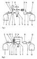
- FIG. 1In the first embodiment of the gas pressure control system according to the invention shown in FIG. 1 is a company bottle 1 filled with liquid gas Bottle valve 2 at a first connection 3 at one end 4a of a three-way element serving T-piece 4 coupled.
- Another end 4b of the T-piece 4communicates with an operating pressure regulator 5, the third terminal 6 for a consumer, not shown, for. B. a heater in a caravan, with pressure-reduced gas of z. B. 30 mbar fed.
- a pressure switch 8At a still free third end 4c of the T-piece 4 are one after the other Pressure gauge serving pressure gauge 7, a pressure switch 8, a check valve 9 and a medium pressure regulator 10 are arranged.
- the medium pressure regulator 10will via a second connection 11 from a liquid gas also filled Reserve bottle 12 fed with a bottle valve 13.
- the check valve 9is installed such that there is only a gas flow of allows the medium pressure regulator 10 to the T-piece 4, but not vice versa.
- the operating pressure regulator 5When requested by the consumer, the operating pressure regulator 5 generates one Gas flow at the third connection 6 with a gas pressure of 30, for example mbar. Due to the bottle pressure at the check valve 9 (16 bar) the check valve 9 is kept closed. On the other side of the Check valve 9 is a regulated by the medium pressure regulator 10 and the reserve bottle 12 fed gas pressure of, for example, 600 mbar, the is not sufficient to open the check valve 9. This will on the one hand ensures that the high bottle pressure from the operating bottle 1 is not in existing between the check valve 9 and the medium pressure regulator 10 Penetrate pipes or hoses 14 and possibly cause interference can. On the other hand, it is prevented that already in regular operation, i. H. at Removal from the operating bottle 1, also gas from the reserve bottle 12 can be, so that an unnoticed emptying of the reserve bottle 12th is prevented.
- the operatorcan use the manometer 7 Read the status of the system. If the manometer 7 has a pressure in the Order of magnitude of the pressure from the medium pressure regulator 10 means that that the operating bottle 1 is at least largely emptied.
- This statecan also be caused by the pressure switch 8 serving as a signal transmitter be recognized, the signal when the pressure falls below the predetermined generated that is displayed, for example, inside the vehicle to be heated can be.
- the pressure switch 8can also be coupled directly to the check valve 9 be and a position or a switching state of the check valve 9 detect and display.
- the second embodiment of the invention shown in FIG. 2basically has the same functionality.
- the T-pieceis 4, the operating pressure regulator 5 and the check valve 9 combined in one unit 20.
- the assembly 20can, for. B. be formed by a cast housing, whereby the separation and thus still required in the first embodiment Have sealing points between the individual components avoided. A reduced one The result is assembly and maintenance effort.
- the manometer 7 and / or the Pressure switch 8are integrated, thereby avoiding further sealing points to let. If necessary, it is also possible to use the manometer 7 or the Pressure switch 8 between the bottle valve 2 and the assembly 20 still also to be installed in the system.
Landscapes
- Engineering & Computer Science (AREA)
- Mechanical Engineering (AREA)
- General Engineering & Computer Science (AREA)
- Filling Or Discharging Of Gas Storage Vessels (AREA)
Description
Translated fromGermanDie Erfindung betrifft eine Gasdruckregelanlage.The invention relates to a gas pressure control system.
Gasdruckregelanlagen finden z. B. bei der Versorgung eines Verbrauchers ineinem Wohnwagen oder Caravan mit Brenngas Verwendung. Dazu wird die Gasdruckregelanlagean dem Flaschenventil einer Flüssiggas aufnehmenden Versorgungsflascheangeschraubt oder mittels eines Hochdruckschlauchs angekoppelt.Der in der Gasdruckregelanlage vorgesehene Betriebsdruckregler regelt den hohenFlaschendruck (z. B. 16 bar) auf einen für den nachgeschalteten Verbrauchergeeigneten Betriebsdruck (z. B. 30 mbar) herunter.Gas pressure control systems can be found e.g. B. in the supply of a consumer ina caravan or caravan using fuel gas. For this, the gas pressure control systemon the bottle valve of a supply bottle that holds liquid gasscrewed on or coupled by means of a high pressure hose.The operating pressure regulator provided in the gas pressure control system regulates the high oneBottle pressure (e.g. 16 bar) to one for the downstream consumersuitable operating pressure (e.g. 30 mbar).
Für den Nutzer ist es sehr komfortabel, wenn außer der als Betriebsflaschedienenden Gasversorgungsflasche noch eine weitere, als Reserveflasche dienendeGasflasche vorgesehen ist. Beim Umschalten der Gasversorgung von derBetriebsflasche zur Reserveflasche kann ihm auf verschiedene Weise mitgeteiltwerden, daß sich seine Gasvorräte dem Ende zu neigen und ein Austausch vonzumindest der Betriebsflasche erforderlich ist.It is very convenient for the user if, in addition to being a company bottleserving gas supply bottle still another, serving as a reserve bottleGas bottle is provided. When switching the gas supply from theCompany bottle to the reserve bottle can be communicated to him in different waysbe that his gas reserves are running out and an exchange ofat least the operating bottle is required.
Zu diesem Zweck ist es bekannt (z. B. die Gasdruckregelanlage "DUOMATIC" derTRUMA Gerätetechnik GmbH & Co.) jede der Flaschen mit einem eigenen Druckreglerzu versehen, wobei der zu der Betriebsflasche gehörende Betriebsdruckreglerauf einen etwas höheren Wert (z. B. 33 mbar) eingestellt ist als ein zu derReserveflasche gehörender Reservedruckregler (z. B. 27 mbar). Die Reglerausgängewerden über ein T-Stück zusammengeführt und mit dem Verbraucher verbunden.Dadurch stehen die von den Reglern abgegebenen Drücke gegeneinander,so daß im Falle einer Gasanforderung vom Verbraucher zunächst ausschließlichDruck von der Betriebsflasche geliefert wird. Erst wenn die Betriebsflascheso weit entleert ist, daß der Betriebsdruckregler nicht mehr den vorgewähltenDruckwert halten kann, wodurch der Versorgungsdruck zum Verbraucherabsinkt, wird der Reservedruckregler aktiv und die Reserveflasche beginntsich zu entleeren. Zu diesem Zeitpunkt ist allerdings die Betriebsflasche bereitsweitgehend erschöpft.For this purpose it is known (e.g. the "DUOMATIC" gas pressure control system fromTRUMA Geräteechnik GmbH & Co.) each of the bottles with its own pressure regulatorto be provided, the operating pressure regulator belonging to the operating bottleis set to a somewhat higher value (e.g. 33 mbar) than one toReserve pressure regulator belonging to the reserve bottle (e.g. 27 mbar). The controller outputsare brought together via a T-piece and connected to the consumer.This means that the pressures emitted by the regulators stand against each other,so that in the event of a gas request from the consumer initially exclusivelyPressure is supplied by the company bottle. Only when the company bottleis so far drained that the operating pressure regulator is no longer the preselected oneCan maintain pressure value, reducing the supply pressure to the consumerdrops, the reserve pressure regulator becomes active and the reserve bottle beginsto empty yourself. At this point, however, the company bottle is already therelargely exhausted.
Ähnliche Gasdruckregelanlagen sind auch aus der DE 298 02 433 U1, derDE-GM 722 91 47 und der DE-GM 169 04 91 bekannt. Auch hier ist es möglich,zwischen einer ersten und einer zweiten Gasvorratsflasche umzuschalten, wobei die Wirkprinzipien dieser Anlagen darauf beruhen, dass für jede Gasvorratsflascheein separates Druckminderventil vorhanden ist, die Druckräume der beidenDruckminderventile miteinander verbunden sind und die Druckminderventileauf unterschiedlich hohe Regeldrücke eingestellt sind. Sinkt der Druck inder einen Gasflasche unter den Druck, der an dem Druckminderventil für denniedrigeren Druck eingestellt ist, erfolgt eine selbsttätige Umschaltung auf dieandere Gasvorratsflasche.Similar gas pressure control systems are also from DE 298 02 433 U1, theDE-GM 722 91 47 and DE-GM 169 04 91 are known. It is also possible hereto switch between a first and a second gas storage bottle, whereinThe operating principles of these systems are based on the fact that for every gas storage bottlea separate pressure reducing valve is available, the pressure chambers of the twoPressure reducing valves are interconnected and the pressure reducing valvesare set to different high control pressures. The pressure drops inthe one gas bottle under the pressure on the pressure reducing valve for thelower pressure is set, an automatic switchover toother gas storage bottle.
Noch komfortabler ist eine Lösung, bei der jede der Gasflaschen mit einemMitteldruckregler ausgestattet ist, wobei der Mitteldruckregler der Betriebsflascheauf einen höheren Wert (z. B. 600 mbar) eingestellt ist als der Mitteldruckreglerder Reserveflasche (z. B. 300 mbar). Die Ausgänge der Mitteldruckreglerwerden wiederum zusammengeführt und an einen Betriebsdruckreglergeleitet, der den für den Verbraucher erforderlichen Betriebsdruck (z. B. 30mbar) einstellt. Bei dieser Anordnung kann das Umschalten zwischen derBetriebsflasche und der Reserveflasche noch zuverlässiger erfolgen. Vor allemwird ein versehentliches vorzeitiges Entleeren der Reserveflasche, was bei derzuerst geschilderten Lösung bei großer Gasmengenanforderung und einemdurch einen begrenzten Durchlaß begründeten niedrigen Druck sowie einer zugeringen Differenz zwischen den eingestellten Drücken der Flaschenregler möglichist, vermieden.Even more convenient is a solution in which each of the gas cylinders comes with oneMedium pressure regulator is equipped, the medium pressure regulator of the operating bottleis set to a higher value (e.g. 600 mbar) than the medium pressure regulatorthe reserve bottle (e.g. 300 mbar). The outputs of the medium pressure regulatorare in turn merged and sent to an operating pressure regulatordirected to the operating pressure required by the consumer (e.g. 30mbar). With this arrangement, switching between theOperating bottle and the reserve bottle are made even more reliably. Especiallyis an accidental premature emptying of the reserve bottle, which in thefirst described solution with a large gas quantity requirement and onedue to a limited passage low pressure and a tooslight difference between the set pressures of the bottle regulator possibleis avoided.
Auch wenn sich die geschilderten Lösungen in der Praxis bereits hervorragendbewährt haben, erfordern sie einen nicht unerheblichen baulichen Aufwand, derinsbesondere im Falle einer Nachrüstung einer bereits vorhandenen Gasversorgungsanlagezu nicht unerheblichen Kosten führen kann.Even if the solutions described are already excellent in practicehave proven themselves, they require a not inconsiderable structural effort thatespecially in the case of retrofitting an existing gas supply systemcan lead to not inconsiderable costs.
Der Erfindung liegt die Aufgabe zugrunde, eine Gasdruckregelanlage anzugeben,die unter Beibehaltung der funktionellen Vorteile der bereits bekannten Anlageneinfacher aufgebaut ist, weniger Teile benötigt und ohne großen Aufwand nachrüstbarist.The invention has for its object to provide a gas pressure control system,that while maintaining the functional advantages of the already known systemsis simpler in construction, requires fewer parts and can be easily retrofittedis.
Die Aufgabe wird durch eine erfindungsgemäße Gasdruckregelanlage gemäßPatentanspruch 1 gelöst.The object is achieved by a gas pressure control system according to the
Bei der erfindungsgemäßen Gasdruckregelanlage sind drei Anschlüsse zumAnschließen von zwei Gasvorratsflaschen und einem Verbraucher vorgesehen, wobei - wie bereits bekannt - vor dem dritten Anschluß für den Verbraucher einBetriebsdruckregler angebracht ist. Der Betriebsdruckregler wird mit demersten Anschluß, der zum Anschließen der Betriebsflasche dient, über ein Dreiwegeelementgekoppelt, an dessen dann noch freiem Ende ein Ventil, vorzugsweiseein Rückschlagventil, vorgesehen ist, das seinerseits mit einem an demzweiten Anschluß und damit an der Reserveflasche vorgesehenen Mitteldruckreglergekoppelt ist. Das Ventil ist derart gestaltet, daß es eine Gasströmungnur in eine Richtung zuläßt, und zwar von dem Mitteldruckregler zu dem Dreiwegeelement.Dies aber auch nur dann, wenn ein Druckabfall der Strömungüber dem Ventil besteht, d. h., wenn der Druck auf der Dreiwegeelement-Seiteniedriger ist als der Druck auf der Seite des Mitteldruckreglers.In the gas pressure control system according to the invention, three connections are toConnection of two gas storage bottles and one consumer providedwhereby - as already known - before the third connection for the consumerOperating pressure regulator is attached. The operating pressure regulator is connected to thefirst connection, which is used to connect the operating bottle, via a three-way elementcoupled, at the then still free end a valve, preferablya check valve is provided, which in turn with one on thesecond connection and thus the medium pressure regulator provided on the reserve bottleis coupled. The valve is designed so that there is a gas flowallows only in one direction, from the medium pressure regulator to the three-way element.But this only if there is a pressure drop in the flowover the valve, d. i.e. when the pressure is on the three-way element sideis lower than the pressure on the side of the medium pressure regulator.
Bei dieser Anordnung wird zunächst nur Gas aus der Betriebsflasche entnommenund über den Betriebsdruckregler auf den für den Verbrauchererforderlichen Betriebsdruck heruntergeregelt. Dabei wird durch das Ventil verhindert,daß Gas mit Flaschendruck in den Bereich des Mitteldruckreglers bzw.einen Schlauch- oder Rohrabschnitt zwischen dem Ventil und dem Mitteldruckreglergelangt. Sobald die Betriebsflasche leer ist, fällt der Druck vor demBetriebsdruckregler unter den Regeldruck des Mitteldruckreglers, woraufhin dasVentil und der Mitteldruckregler öffnen und Gas aus der Reserveflasche entnommenwird.With this arrangement, initially only gas is withdrawn from the operating bottleand via the operating pressure regulator to that for the consumerrequired operating pressure reduced. The valve preventsthat gas with cylinder pressure in the area of the medium pressure regulator ora hose or pipe section between the valve and the medium pressure regulatorarrives. As soon as the operating bottle is empty, the pressure in front of theOperating pressure regulator below the control pressure of the medium pressure regulator, whereupon theOpen the valve and the medium pressure regulator and remove gas from the reserve bottlebecomes.
Die erfindungsgemäße Gasdruckregelanlage läßt sich in einfacher Weise auchbei bestehenden Gasversorgungsanlagen, bei denen z. B. eine Versorgungsflaschemit Betriebsdruckregler vorhanden ist, nachrüsten, indem das Dreiwegeelementzwischen dem zur Flache gehörigen Flaschenventil und dem vorhandenenBetriebsregler zusammen mit den weiteren Bauelementen eingebaut wird.Dies hat den Vorteil, daß die bereits vorhandenen Bauelemente ihre Funktionbehalten und somit auch nach der Erweiterung kein Bauelement überflüssigwird, was eine wirtschaftliche Nutzung aller Komponenten ermöglicht.The gas pressure control system according to the invention can also be carried out in a simple mannerin existing gas supply systems, in which e.g. B. a supply bottlewith operating pressure regulator, retrofit by the three-way elementbetween the bottle valve belonging to the flat and the existing oneOperating controller is installed together with the other components.This has the advantage that the already existing components functionRetain and therefore no component is superfluous even after the expansionbecomes what enables an economical use of all components.
Bei einer besonders vorteilhaften Weiterentwicklung der Erfindung sind derBetriebsdruckregler, das Dreiwegeelement und das Ventil zu einer Baueinheit, z.B. in einem Gußgehäuse, zusammengefaßt. Dadurch lassen sich Dichtstellenzwischen den genannten Bauelementen vermeiden, was den Montage- undWartungsaufwand erheblich vermindert.In a particularly advantageous further development of the inventionOperating pressure regulator, the three-way element and the valve to form a structural unit, e.g.B. summarized in a cast housing. This allows sealing pointsbetween the components mentioned avoid what the assembly andMaintenance effort significantly reduced.
Bei einer weiteren vorteilhaften Ausbildung der Erfindung ist eine Druckanzeigezum Anzeigen eines Drucks vor dem Betriebsdruckregler vorgesehen. Weiterhinkann ein druckbeaufschlagbarer Signalgeber vorhanden sein, der bei Unterschreiteneines vorgegebenen Drucks in der Anlage ein Signal abgibt, das demNutzer - z. B. im Innenraum seines Wohnwagens - angezeigt werden kann. DerSignalgeber kann auch derart ausgebildet sein, daß er eine Ventilstellung desRückschlagventils erfaßt.In a further advantageous embodiment of the invention, a pressure displayprovided to display a pressure upstream of the operating pressure regulator. Fartherthere may be a signaling device that can be pressurized, which falls belowa predetermined pressure in the system emits a signal that theUsers - e.g. B. in the interior of his caravan - can be displayed. TheSignal generator can also be designed such that it has a valve position of theCheck valve detected.
Diese und weitere Vorteile und Merkmale der Erfindung werden nachfolgendanhand mehrerer Beispiele unter Zuhilfenahme der Figuren näher erläutert. Eszeigen:
- Fig. 1
- eine erste Ausführungsform einer erfindungsgemäßen Gasdruckregelanlage:und
- Fig. 2
- eine zweite Ausführungsform der Gasdruckregelanlage.
- Fig. 1
- a first embodiment of a gas pressure control system according to the invention: and
- Fig. 2
- a second embodiment of the gas pressure control system.
Bei der in Fig. 1 gezeigten ersten Ausführungsform der erfindungsgemäßen Gasdruckregelanlageist eine mit Flüssiggas gefüllte Betriebsflasche 1 mit einemFlaschenventil 2 an einem ersten Anschluß 3 an ein Ende 4a eines als Dreiwegeelementdienenden T-Stücks 4 angekoppelt.In the first embodiment of the gas pressure control system according to the invention shown in FIG. 1is a
Ein weiteres Ende 4b des T-Stücks 4 kommuniziert mit einem Betriebsdruckregler5, der einen dritten Anschluß 6 für einen nicht dargestellten Verbraucher, z.B. eine Heizung in einem Caravan, mit druckreduziertem Gas von z. B. 30 mbarspeist.Another
An einem noch freien dritten Ende 4c des T-Stücks 4 sind nacheinander ein alsDruckanzeige dienendes Manometer 7, ein Druckschalter 8, ein Rückschlagventil9 und ein Mitteldruckregler 10 angeordnet. Der Mitteldruckregler 10 wirdüber einen zweiten Anschluß 11 von einer ebenfalls mit Flüssiggas gefülltenReserveflasche 12 mit einem Flaschenventil 13 gespeist.At a still free
Das Rückschlagventil 9 ist derart eingebaut, daß es nur eine Gasströmung vondem Mitteldruckregler 10 zu dem T-Stück 4 zuläßt, jedoch nicht umgekehrt.The
Nachfolgend wird die Funktion der Druckregelanlage erläutert.The function of the pressure control system is explained below.
Zunächst liegt ein Gasdruck von der Betriebsflasche 1 mit beispielsweise 16 baran dem T-Stück 4, dem Betriebsdruckregler 5 und dem Rückschlagventil 9 an.Bei Anforderung durch den Verbraucher erzeugt der Betriebsdruckregler 5 einenGasstrom am dritten Anschluß 6 mit einem Gasdruck von beispielsweise 30mbar. Durch den am Rückschlagventil 9 anliegenden Flaschendruck (16 bar)wird das Rückschlagventil 9 geschlossengehalten. Auf der anderen Seite desRückschlagventils 9 liegt ein von dem Mitteldruckregler 10 geregelter und vonder Reserveflasche 12 gespeister Gasdruck von beispielsweise 600 mbar an, dernicht ausreicht, um das Rückschlagventil 9 zu öffnen. Dadurch wird einerseitssichergestellt, daß der hohe Flaschendruck aus der Betriebsflasche 1 nicht inzwischen dem Rückschlagventil 9 und dem Mitteldruckregler 10 vorhandeneRohre oder Schläuche 14 eindringen und möglicherweise Störungen hervorrufenkann. Zum anderen wird verhindert, daß bereits im regulären Betrieb, d. h. beiEntnahme aus der Betriebsflasche 1, auch Gas aus der Reserveflasche 12 entnommenwerden kann, so daß ein unbemerktes Entleeren der Reserveflasche 12verhindert wird.First, there is a gas pressure from the
Erst wenn die Betriebsflasche 1 soweit entleert ist, daß sie nur noch einenDruck bereitsstellt, der unter dem vom Mitteldruckregler 10 geregeltenDruck - im vorliegenden Beispiel also unter 600 mbar - liegt, öffnet das Rückschlagventil9 und Gas kann von der Reserveflasche 12 über den Mitteldruckregler10 und das Rückschlagventil 9 zu dem Betriebsdruckregeler 5 strömen.Only when the
Zur Erhöhung des Komforts kann der Bediener an dem Manometer 7 denZustand der Anlage ablesen. Wenn nämlich das Manometer 7 einen Druck in derGrößenordnung des Drucks von dem Mitteldruckregler 10 anzeigt, bedeutet das,daß die Betriebsflasche 1 zumindest weitgehend geleert ist.To increase comfort, the operator can use the
Dieser Zustand kann auch von dem als Signalgeber dienenden Druckschalter 8erkannt werden, der bei Unterschreiten des vorgegebenen Drucks ein Signalerzeugt, das beispielsweise im Inneren des zu beheizenden Fahrzeugs angezeigtwerden kann.This state can also be caused by the
Der Druckschalter 8 kann auch direkt mit dem Rückschlagventil 9 gekoppeltsein und eine Stellung bzw. einen Schaltzustand des Rückschlagventils 9detektieren und anzeigen.The
Die in Fig. 2 gezeigte zweite Ausführungsform der Erfindung weist prinzipiell diegleiche Funktionalität auf. Jedoch sind das T-Stück 4, der Betriebsdruckregler5 und das Rückschlagventil 9 in einer Baueinheit 20 zusammengefaßt.The second embodiment of the invention shown in FIG. 2 basically has thesame functionality. However, the T-piece is 4, the operating
Die Baueinheit 20 kann z. B. durch ein Gußgehäuse gebildet werden, wodurchsich die bei der ersten Ausführungsform noch erforderlichen Trenn- und damitDichtstellen zwischen den einzelnen Bauelementen vermeiden lassen. Ein reduzierterMontage- und Wartungsaufwand ist die Folge.The
Wenn die Anlage mit nur einer Betriebsflasche, jedoch ohne Reserveflasche betriebenwerden soll, kann ein Eingang 21 am Rückschlagventil 9 mit einemnicht dargestellten Gewindestück dicht verschlossen werden. Um den Hochdruckschlauch14 anschließen zu können, ist es zweckmäßig, den Eingang 21für den Schlauchanschluß vorzubereiten.If the system is operated with only one company bottle, but without a reserve bottlecan be, an
In die Baueinheit 20 können weiterhin auch das Manometer 7 und/oder derDruckschalter 8 integriert werden, wodurch sich weitere Dichtstellen vermeidenlassen. Falls erforderlich, ist es aber auch möglich, das Manometer 7 oder denDruckschalter 8 zwischen dem Flaschenventil 2 und der Baueinheit 20 nochzusätzlich in die Anlage einzubauen.In the
Claims (6)
- Gas pressure regulating system havinga first connection (3) for connecting a first gas supply cylinder (1);a second connection (11) for a second gas supply cylinder (12);a third connection (6) for a consumer;an operating pressure regulator (5) arranged upstream of the third connection (6)seen in the flow direction;a three-way element (4) coupling the first connection (3) to the operaring pressureregulator (5); and havinga valve (9) permitting flow only in one direction, which is arranged between thestill free end of the three-way element (4) and a mean pressure regulator (10)provided at the second connection (11) such that flow is permitted only from themean pressure regulator (10) to the three-way element (4), and this also only for apressure drop in the flow via the valve (9).
- Gas pressure regulating system according to claim 1,characterised in that theoperating pressure regulator (5), the three-way element (4) and the valve (9) arecombined to form a constructional unit (20).
- Gas pressure regulating system according to claim 1 or 2,characterised in that apressure display (7) for displaying a pressure is provided between the first counection(3), the valve (9) and the operating pressure regulator (5).
- Gas pressure regulating system according to one of claims 1 to 3,characterised inthat a signal transmitter (8) which can be exposed to pressure is preset for releasing asignal when a preset pressure is not reached in the system.
- Gas pressure regulating system according to one of claims 1 to 3,characterised inthat a signal transmitter is provided for releasing a signal when the valve (9) isopened.
- Gas pressure regulating system according to one of claims 1 to 5,characterised inthat the valve is a nonreturn valve (9).
Applications Claiming Priority (2)
| Application Number | Priority Date | Filing Date | Title |
|---|---|---|---|
| DE19936374 | 1999-08-03 | ||
| DE19936374ADE19936374C2 (en) | 1999-08-03 | 1999-08-03 | Gas pressure control system |
Publications (2)
| Publication Number | Publication Date |
|---|---|
| EP1079292A1 EP1079292A1 (en) | 2001-02-28 |
| EP1079292B1true EP1079292B1 (en) | 2002-05-22 |
Family
ID=7916933
Family Applications (1)
| Application Number | Title | Priority Date | Filing Date |
|---|---|---|---|
| EP00116540AExpired - LifetimeEP1079292B1 (en) | 1999-08-03 | 2000-07-31 | Gas pressure regulator |
Country Status (2)
| Country | Link |
|---|---|
| EP (1) | EP1079292B1 (en) |
| DE (2) | DE19936374C2 (en) |
Cited By (4)
| Publication number | Priority date | Publication date | Assignee | Title |
|---|---|---|---|---|
| USD905217S1 (en) | 2018-09-05 | 2020-12-15 | Dometic Sweden Ab | Air conditioning apparatus |
| USD907183S1 (en) | 2016-11-23 | 2021-01-05 | Dometic Sweden Ab | Air conditioning apparatus |
| US11772452B2 (en) | 2017-11-16 | 2023-10-03 | Dometic Sweden Ab | Air conditioning apparatus for recreational vehicles |
| US12043081B2 (en) | 2019-10-17 | 2024-07-23 | Dometic Sweden Ab | Air conditioning apparatus for recreational vehicles |
Families Citing this family (2)
| Publication number | Priority date | Publication date | Assignee | Title |
|---|---|---|---|---|
| DE10162092A1 (en)* | 2001-12-18 | 2003-07-17 | Gok Regler Und Armaturengmbh & | Device for automatically switching a first liquid gas container to a second liquid gas container |
| AT505960B1 (en)* | 2007-10-25 | 2009-07-15 | Ventrex Automotive Gmbh | TANK AND FUEL SUPPLY SYSTEM |
Family Cites Families (6)
| Publication number | Priority date | Publication date | Assignee | Title |
|---|---|---|---|---|
| DE7229147U (en)* | 1972-10-26 | Officine Meccaniche E Balsamo Srl | Double pressure regulator for pairs of gas cylinders | |
| DE1690491U (en)* | 1954-10-30 | 1954-12-30 | Rudolf Majert G M B H | SELF-ACTING CHANGEOVER VALVE FOR LIQUID GAS TANK. |
| US3604632A (en)* | 1969-11-12 | 1971-09-14 | Golconda Corp | Flame cutting tip |
| US3813916A (en)* | 1973-03-19 | 1974-06-04 | Textron Inc | Meter proving system |
| US4023593A (en)* | 1976-02-17 | 1977-05-17 | The Rucker Company | Valve and control therefor |
| DE29802433U1 (en)* | 1998-02-16 | 1998-09-17 | GOK Regler- und Armaturen- Gesellschaft mbH & Co. KG, 97342 Seinsheim | Automatic valve for LPG |
- 1999
- 1999-08-03DEDE19936374Apatent/DE19936374C2/ennot_activeExpired - Fee Related
- 2000
- 2000-07-31EPEP00116540Apatent/EP1079292B1/ennot_activeExpired - Lifetime
- 2000-07-31DEDE50000177Tpatent/DE50000177D1/ennot_activeExpired - Fee Related
Cited By (5)
| Publication number | Priority date | Publication date | Assignee | Title |
|---|---|---|---|---|
| USD907183S1 (en) | 2016-11-23 | 2021-01-05 | Dometic Sweden Ab | Air conditioning apparatus |
| US11772452B2 (en) | 2017-11-16 | 2023-10-03 | Dometic Sweden Ab | Air conditioning apparatus for recreational vehicles |
| USD905217S1 (en) | 2018-09-05 | 2020-12-15 | Dometic Sweden Ab | Air conditioning apparatus |
| USD944374S1 (en) | 2018-09-05 | 2022-02-22 | Dometic Sweden Ab | Air conditioning apparatus |
| US12043081B2 (en) | 2019-10-17 | 2024-07-23 | Dometic Sweden Ab | Air conditioning apparatus for recreational vehicles |
Also Published As
| Publication number | Publication date |
|---|---|
| DE50000177D1 (en) | 2002-06-27 |
| DE19936374A1 (en) | 2001-02-22 |
| DE19936374C2 (en) | 2001-06-13 |
| EP1079292A1 (en) | 2001-02-28 |
Similar Documents
| Publication | Publication Date | Title |
|---|---|---|
| EP3479008A1 (en) | Tank valve | |
| EP0158982A2 (en) | Security valve for liquefied-gas tanks, particularly for ship tanks | |
| DE3806998A1 (en) | CONTROL UNIT FOR PRESSURIZED GAS | |
| DE2210362A1 (en) | INDEPENDENT PRESSURE REGULATING VALVE AND ITS APPLICATION IN A COMPRESSED GAS SUPPLY SYSTEM WITH LIQUID GAS | |
| EP1079292B1 (en) | Gas pressure regulator | |
| DE3313645C1 (en) | Valve automatically regulating the operating vacuum for milking systems | |
| DE102004021242B4 (en) | Air treatment plant and method for supplying a commercial vehicle brake system with compressed air | |
| DE102011107490A1 (en) | Multi-circuit protection valve, ventilation method, air treatment device, compressed air system and vehicle for ventilating several vented pressure circuits in a defined order of refilling | |
| CH713883B1 (en) | Pressure holding device. | |
| DE10351095B4 (en) | Air treatment plant and method for supplying a commercial vehicle brake system with compressed air | |
| DE3213236A1 (en) | DEVICE WITH AN AIR DRYER FOR COMPRESSED AIR SYSTEMS | |
| DE10342978B4 (en) | Air treatment plant and method for supplying a commercial vehicle brake system with compressed air | |
| CH623912A5 (en) | Monitoring device at the supply line of an oil-fed unit | |
| DE69012051T2 (en) | Hydraulic valve arrangement. | |
| DE102007020352B4 (en) | Filter clogging detection system | |
| DE2453466C2 (en) | Pressure ratio valve | |
| DE69807921T2 (en) | VALVE UNIT FOR REGULATING THE FLOW OF A PRESSURE | |
| DE2352147C3 (en) | Device for supplying a cryostat | |
| DE2336589C2 (en) | Safety system for a dampening solution preparation container in an offset printing machine | |
| DE19930610B4 (en) | Control device for a compressor | |
| AT130193B (en) | Central lubrication device. | |
| DE3916162A1 (en) | By=pass system supplying oil and water emulsion - is for mining machine and is actuated by manual opening of stop valve | |
| DE8815256U1 (en) | Gas filter | |
| EP4402402A1 (en) | System with cryogenic container and a single-piece pressure management system | |
| DE3910813A1 (en) | DEVICE FOR INSERTING A GAS INTO A CASE AND FOR REMOVING IT FROM THIS |
Legal Events
| Date | Code | Title | Description |
|---|---|---|---|
| PUAI | Public reference made under article 153(3) epc to a published international application that has entered the european phase | Free format text:ORIGINAL CODE: 0009012 | |
| AK | Designated contracting states | Kind code of ref document:A1 Designated state(s):DE FR GB IT NL SE | |
| AX | Request for extension of the european patent | Free format text:AL;LT;LV;MK;RO;SI | |
| 17P | Request for examination filed | Effective date:20010301 | |
| GRAG | Despatch of communication of intention to grant | Free format text:ORIGINAL CODE: EPIDOS AGRA | |
| 17Q | First examination report despatched | Effective date:20010927 | |
| GRAG | Despatch of communication of intention to grant | Free format text:ORIGINAL CODE: EPIDOS AGRA | |
| GRAH | Despatch of communication of intention to grant a patent | Free format text:ORIGINAL CODE: EPIDOS IGRA | |
| AKX | Designation fees paid | Free format text:DE FR GB IT NL SE | |
| GRAH | Despatch of communication of intention to grant a patent | Free format text:ORIGINAL CODE: EPIDOS IGRA | |
| GRAA | (expected) grant | Free format text:ORIGINAL CODE: 0009210 | |
| REG | Reference to a national code | Ref country code:GB Ref legal event code:FG4D Free format text:NOT ENGLISH | |
| GBT | Gb: translation of ep patent filed (gb section 77(6)(a)/1977) | Effective date:20020523 | |
| REF | Corresponds to: | Ref document number:50000177 Country of ref document:DE Date of ref document:20020627 | |
| ET | Fr: translation filed | ||
| PLBE | No opposition filed within time limit | Free format text:ORIGINAL CODE: 0009261 | |
| STAA | Information on the status of an ep patent application or granted ep patent | Free format text:STATUS: NO OPPOSITION FILED WITHIN TIME LIMIT | |
| 26N | No opposition filed | Effective date:20030225 | |
| PGFP | Annual fee paid to national office [announced via postgrant information from national office to epo] | Ref country code:DE Payment date:20070820 Year of fee payment:8 | |
| PGFP | Annual fee paid to national office [announced via postgrant information from national office to epo] | Ref country code:GB Payment date:20070625 Year of fee payment:8 | |
| PGFP | Annual fee paid to national office [announced via postgrant information from national office to epo] | Ref country code:IT Payment date:20070721 Year of fee payment:8 Ref country code:NL Payment date:20070724 Year of fee payment:8 Ref country code:SE Payment date:20070719 Year of fee payment:8 | |
| PGFP | Annual fee paid to national office [announced via postgrant information from national office to epo] | Ref country code:FR Payment date:20070718 Year of fee payment:8 | |
| GBPC | Gb: european patent ceased through non-payment of renewal fee | Effective date:20080731 | |
| NLV4 | Nl: lapsed or anulled due to non-payment of the annual fee | Effective date:20090201 | |
| EUG | Se: european patent has lapsed | ||
| PG25 | Lapsed in a contracting state [announced via postgrant information from national office to epo] | Ref country code:DE Free format text:LAPSE BECAUSE OF NON-PAYMENT OF DUE FEES Effective date:20090203 | |
| REG | Reference to a national code | Ref country code:FR Ref legal event code:ST Effective date:20090331 | |
| PG25 | Lapsed in a contracting state [announced via postgrant information from national office to epo] | Ref country code:NL Free format text:LAPSE BECAUSE OF NON-PAYMENT OF DUE FEES Effective date:20090201 | |
| PG25 | Lapsed in a contracting state [announced via postgrant information from national office to epo] | Ref country code:GB Free format text:LAPSE BECAUSE OF NON-PAYMENT OF DUE FEES Effective date:20080731 | |
| PG25 | Lapsed in a contracting state [announced via postgrant information from national office to epo] | Ref country code:IT Free format text:LAPSE BECAUSE OF NON-PAYMENT OF DUE FEES Effective date:20080731 Ref country code:FR Free format text:LAPSE BECAUSE OF NON-PAYMENT OF DUE FEES Effective date:20080731 | |
| PG25 | Lapsed in a contracting state [announced via postgrant information from national office to epo] | Ref country code:SE Free format text:LAPSE BECAUSE OF NON-PAYMENT OF DUE FEES Effective date:20080801 |