EP1079159A1 - Manual valve - Google Patents
Manual valveDownload PDFInfo
- Publication number
- EP1079159A1 EP1079159A1EP00202993AEP00202993AEP1079159A1EP 1079159 A1EP1079159 A1EP 1079159A1EP 00202993 AEP00202993 AEP 00202993AEP 00202993 AEP00202993 AEP 00202993AEP 1079159 A1EP1079159 A1EP 1079159A1
- Authority
- EP
- European Patent Office
- Prior art keywords
- safety
- lever
- axis
- rotation
- valve
- Prior art date
- Legal status (The legal status is an assumption and is not a legal conclusion. Google has not performed a legal analysis and makes no representation as to the accuracy of the status listed.)
- Withdrawn
Links
Images

Classifications
- F—MECHANICAL ENGINEERING; LIGHTING; HEATING; WEAPONS; BLASTING
- F16—ENGINEERING ELEMENTS AND UNITS; GENERAL MEASURES FOR PRODUCING AND MAINTAINING EFFECTIVE FUNCTIONING OF MACHINES OR INSTALLATIONS; THERMAL INSULATION IN GENERAL
- F16K—VALVES; TAPS; COCKS; ACTUATING-FLOATS; DEVICES FOR VENTING OR AERATING
- F16K35/00—Means to prevent accidental or unauthorised actuation
- F16K35/02—Means to prevent accidental or unauthorised actuation to be locked or disconnected by means of a pushing or pulling action
- F16K35/022—Means to prevent accidental or unauthorised actuation to be locked or disconnected by means of a pushing or pulling action the locking mechanism being actuated by a separate actuating element
- F16K35/025—Means to prevent accidental or unauthorised actuation to be locked or disconnected by means of a pushing or pulling action the locking mechanism being actuated by a separate actuating element said actuating element being operated manually (e.g. a push-button located in the valve actuator)
Definitions
- the present inventionrelates to a manually operated valve, usable in particular in chemical apparatus and installations.
- valves devices intended to control the flow of fluidsconstitute devices simple but capital, which the staff are generally led to maneuver frequently, and which can cause serious incidents or accidents in improper handling. It is therefore important to develop valves manual whose position cannot be changed unintentionally, by example due to the involuntary contact of a person with the steering wheel or the lever used to actuate the valve.
- valve control leverin normal times (i.e. when no force is exerted on the release handle), the valve control lever is locked in a fixed position relative to the installation on which the valve is mounted. Since the valves most of the time they are installed in places where staff are likely to flow (for obvious reasons of access to manual valves or work to be carried out nearby in particular), the presence of a lever can be immobilized in different positions, generally presenting an elongated shape, constitutes a danger to the safety of personnel, who may come up against this lever and be the victim of potentially serious injuries and / or painful.
- the blocking deviceis generally not of extreme solidity, and that the shock of a person, a vehicle or another object with the lever can damage or destroy the lever, in such a way that the lever (or what remains of it) is then able to move move freely (whether as a result of this same shock or other subsequent influences), which can undesirably alter the flow fluid in the piping on which the valve is mounted. It is clear that in an industrial chemical installation, interruption or establishment untimely fluid flow can have dramatic consequences.
- the present inventiontherefore aims to provide a manual valve which does not not have these drawbacks.
- the present inventionrelates to a manual valve, comprising a closure device (1) capable of influencing the flow of a fluid in a conduit in which the valve is installed, as well as a device for security (2), said closure device (1) being movable by an operator by means of a control member (3) pivoting about an axis, characterized in that a pivoting of the control member (3) does not cause a movement of the shutter device (1) only when the safety device (2) is actuated by the operator, while the control member (3) can pivot freely without causing the shutter device (1) to move when said safety device (2) is not actuated.
- valvewe mean any device allowing to influence - in particular to interrupt - the flow of a fluid in a conduit (piping, etc.) on which it is installed.
- Many types of valvesare well known from a person skilled in the art, for example valves comprising a cylindrical section of piping in which is disposed a closure device consisting of a disc-shaped metal valve capable of pivoting about an axis diametral perpendicular to the axis of said pipe section.
- valve “manual”means a valve intended to be operated by a human operator, as opposed to valves whose closure device is moved by an electric, pneumatic or other actuator.
- the manual valveis equipped with a rotary control member allowing an operator of the maneuver, this body generally consisting of a lever or steering wheel, capable pivot around an axis of rotation, which axis can be connected to the device shutter directly or indirectly (e.g. via gears).
- a rotary control memberallowing an operator of the maneuver, this body generally consisting of a lever or steering wheel, capable pivot around an axis of rotation, which axis can be connected to the device shutter directly or indirectly (e.g. via gears).
- Some types of valvesinclude a pin with a thread, allowing the obturation device (fixed to said axis) to be moved axially by printing a rotational movement to the axis. It is therefore possible that the axis of rotation undergoes, in addition to rotation, also a slight axial translation.
- control membercomprises at minus a control lever (3) substantially perpendicular to its axis of rotation.
- control member (3)comprises a steering wheel.
- valve safety device of the inventionis that it is designed out only if it is not operated by an operator, not only it is impossible to act on the position of the shutter device, but moreover the control member is free to pivot about its axis, without offering any resistance in the event of untimely impact.
- this particularityoffers considerable advantages not only in terms of operator safety, but also prevents accidental valve misalignment, and reduces the risk of it being damaged in the event of an impact.
- the safety device (2)is provided with return means ensuring that the organ control (3) can pivot freely without causing movement of the shutter device (1) when said safety device (2) is not operated.
- the valvecomprises a part coupling (4) concentric to the axis of rotation, the position of which determines unequivocally the position of the shutter device (1)
- the device safetyincludes a safety lever (2) capable of moving approximately parallel to the axis of rotation, such that the member control (3) can pivot independently of the coupling piece (4) and therefore without causing the displacement of the shutter device (1) when the safety lever (2) is not subjected to any external force, while the pivoting of the control member (3) causes the part to pivot coupling (4) and therefore the displacement of the closure device (1) when the safety lever (2) is actuated by an operator.
- the part couplingis generally provided with notches in which can engage a part connected to the safety lever (for example one end of the lever) when it is activated.
- the coupling piececan in particular be attached concentrically to the axis of rotation or be an integral part thereof.
- controlcomprises at least one control lever (3) substantially perpendicular to its axis of rotation, and the pivoting of the control member (3) causes the coupling piece (4) to pivot and therefore the movement of the closure device (1) when the ends of the control (3) and the safety lever (2) are brought together.
- Means of remindersuch as a spring are advantageously used to keep apart the ends of the control and safety levers in the absence of stress on the safety lever, allowing the control lever to pivot freely without causing the shutter to move.
- a coupling piece (4 ')concentric with said axis of rotation, the position of which determines so unequivocally the position of said shutter device (1)
- the device securityincludes a security plate (2) capable of moving approximately parallel to the axis of rotation, such that the member control (3 ') can pivot independently of the coupling part (4 ') and therefore without causing the displacement of the closure device (1) when the safety plate (2 ') is not subjected to any external force, while the pivoting of the control member (3 ') causes the part to pivot coupling (4 ') and therefore the displacement of the closure device (1) when the safety plate (2 ') is actuated by an operator so that it is closer to the control member (3 ').
- the coupling pieceis generally of substantially cylindrical shape, and bears on its face upper notches into which protrusions can engage attached to the security plate.
- the coupling piececan in particular be fixed concentrically with the axis of rotation or form part of it integral.
- Return meanssuch as one or more springs are advantageously used to keep the safety plate and the member apart control in the absence of external stress on the safety plate, thus allowing the control member to pivot freely without causing the displacement of the shutter device.
- Return meanssuch as one or more springs are advantageously used to maintain the safety lever in its position the closer to the axis of rotation in the absence of external stress.
- This third variantalso applies to cases where the control includes a lever only to those where the control member includes a steering wheel.
Landscapes
- Engineering & Computer Science (AREA)
- General Engineering & Computer Science (AREA)
- Mechanical Engineering (AREA)
- Mechanical Control Devices (AREA)
- Mechanically-Actuated Valves (AREA)
Abstract
Description
Translated fromFrenchLa présente invention concerne une vanne à commande manuelle,utilisable notamment dans les appareillages et installations chimiques.The present invention relates to a manually operated valve,usable in particular in chemical apparatus and installations.
Dans les installations chimiques industrielles notamment, les vannesmanuelles destinées à contrôler l'écoulement de fluides constituent des dispositifssimples mais capitaux, que le personnel est généralement amené à manoeuvrerfréquemment, et qui peuvent être à l'origine d'incidents ou accidents graves encas de manipulation incorrecte. Il importe donc de développer des vannesmanuelles dont la position ne puisse pas être modifiée involontairement, parexemple sous l'effet du contact involontaire d'une personne avec le volant ou lelevier servant à actionner la vanne.In industrial chemical installations in particular, valvesdevices intended to control the flow of fluids constitute devicessimple but capital, which the staff are generally led to maneuverfrequently, and which can cause serious incidents or accidents inimproper handling. It is therefore important to develop valvesmanual whose position cannot be changed unintentionally, byexample due to the involuntary contact of a person with the steering wheel or thelever used to actuate the valve.
De nombreuses solutions ont déjà été proposées dans ce but. Parexemple, le document US 5598724 décrit une vanne manuelle dont le levier decommande, en l'absence de sollicitation extérieure, est empêché de pivoter grâceà un ergot de blocage s'engageant dans l'une des encoches pratiquées dans undisque fixé rigidement au corps de la vanne, ce disque étant concentrique à l'axede rotation du levier de commande. Pour manoeuvrer cette vanne, il estnécessaire d'appuyer sur une poignée de déblocage, de façon à dégager leditergot de l'encoche.Many solutions have already been proposed for this purpose. Throughexample, document US 5598724 describes a manual valve whose levercontrol, in the absence of external stress, is prevented from pivoting byto a locking lug engaging in one of the notches made in adisc rigidly fixed to the valve body, this disc being concentric with the axiscontrol lever rotation. To operate this valve, it isnecessary to press on a release handle, so as to release saidnotch lug.
Ce dispositif présente plusieurs inconvénients. En effet, en temps normal(c'est-à-dire lorsqu'aucune force n'est exercée sur la poignée de déblocage), lelevier de commande de la vanne est bloqué dans une position fixe par rapport àl'installation sur laquelle la vanne est montée. Etant donné que les vannesmanuelles sont la plupart du temps installées en des endroits où le personnel estsusceptible de circuler (pour des raisons évidentes d'accès aux vannes manuellesou travaux à effectuer à proximité notamment), la présence d'un leviersusceptible d'être immobilisé dans différentes positions, présentant généralementune forme allongée, constitue un danger pour la sécurité du personnel, qui risquede se heurter à ce levier et d'être victime de lésions potentiellement graves et/oudouloureuses. Un autre inconvénient, potentiellement plus lourd deconséquences encore, est que le dispositif de blocage n'est généralement pasd'une solidité extrême, et que le choc d'une personne, d'un véhicule ou d'un autreobjet avec le levier peut avoir pour conséquence d'endommager ou de détruire le levier, d'une façon telle que le levier (ou ce qu'il en reste) soit alors capable de sedéplacer librement (que ce soit sous l'effet de ce même choc ou d'autresinfluences ultérieures), ce qui peut modifier de manière non désirée l'écoulementdu fluide dans la tuyauterie sur laquelle est montée la vanne. Il est clair que dansune installation chimique industrielle, l'interruption ou l'établissementintempestif d'un débit de fluide peut avoir des conséquences dramatiques.This device has several drawbacks. Indeed, in normal times(i.e. when no force is exerted on the release handle), thevalve control lever is locked in a fixed position relative tothe installation on which the valve is mounted. Since the valvesmost of the time they are installed in places where staff arelikely to flow (for obvious reasons of access to manual valvesor work to be carried out nearby in particular), the presence of a levercan be immobilized in different positions, generally presentingan elongated shape, constitutes a danger to the safety of personnel, who maycome up against this lever and be the victim of potentially serious injuries and / orpainful. Another disadvantage, potentially heavier thanconsequences again, is that the blocking device is generally notof extreme solidity, and that the shock of a person, a vehicle or anotherobject with the lever can damage or destroy thelever, in such a way that the lever (or what remains of it) is then able to movemove freely (whether as a result of this same shock or othersubsequent influences), which can undesirably alter the flowfluid in the piping on which the valve is mounted. It is clear that inan industrial chemical installation, interruption or establishmentuntimely fluid flow can have dramatic consequences.
Il serait certes envisageable de réduire les dimensions de l'organe decommande de la vanne (longueur du levier, etc.), mais ceci en rendrait lamanipulation plus difficile.It would certainly be possible to reduce the dimensions of thevalve control (length of lever, etc.), but this would make itmore difficult handling.
La présente invention vise dès lors à fournir une vanne manuelle qui neprésente pas ces inconvénients.The present invention therefore aims to provide a manual valve which does notnot have these drawbacks.
A cette fin, la présente invention concerne une vanne manuelle,comprenant un dispositif d'obturation (1) capable d'influencer le débit d'un fluidedans un conduit dans lequel est installé la vanne, ainsi qu'un dispositif desécurité (2), ledit dispositif d'obturation (1) pouvant être déplacé par un opérateurpar l'intermédiaire d'un organe de commande (3) pivotant autour d'un axe,caractérisée en ce qu'un pivotement de l'organe de commande (3) ne provoque undéplacement du dispositif d'obturation (1) que lorsque le dispositif de sécurité (2)est actionné par l'opérateur, alors que l'organe de commande (3) peut pivoterlibrement sans provoquer un déplacement du dispositif d'obturation (1) lorsqueledit dispositif de sécurité (2) n'est pas actionné.To this end, the present invention relates to a manual valve,comprising a closure device (1) capable of influencing the flow of a fluidin a conduit in which the valve is installed, as well as a device forsecurity (2), said closure device (1) being movable by an operatorby means of a control member (3) pivoting about an axis,characterized in that a pivoting of the control member (3) does not cause amovement of the shutter device (1) only when the safety device (2)is actuated by the operator, while the control member (3) can pivotfreely without causing the shutter device (1) to move whensaid safety device (2) is not actuated.
Par vanne, on entend désigner tout dispositif permettant d'influencer - enparticulier d'interrompre - le débit d'un fluide dans un conduit (tuyauterie, etc.)sur lequel il est installé. De nombreux types de vannes sont bien connus del'homme du métier, par exemple des vannes comprenant un tronçon cylindriquede tuyauterie dans lequel est disposé un dispositif d'obturation constitué d'unclapet métallique en forme de disque capable de pivoter autour d'un axediamétral perpendiculaire à l'axe dudit tronçon de tuyauterie. Par vanne"manuelle", on entend désigner une vanne destinée à être manoeuvrée par unopérateur humain, par opposition aux vannes dont le dispositif d'obturation estdéplacé par un actionneur électrique, pneumatique ou autre. La vanne manuelleest équipée d'un organe de commande rotatif permettant à un opérateur de lamanoeuvrer, cet organe consistant généralement en un levier ou volant, capablede pivoter autour d'un axe de rotation, lequel axe peut être relié au dispositifd'obturation de manière directe ou indirecte (par exemple par l'intermédiaired'engrenages). Certains types de vannes comprennent un axe muni d'un filetage, permettant de déplacer axialement le dispositif d'obturation (fixé audit axe) enimprimant un mouvement de rotation à l'axe. Il est donc possible que l'axe derotation subisse, outre une rotation, également une légère translation axiale.By valve, we mean any device allowing to influence - inparticular to interrupt - the flow of a fluid in a conduit (piping, etc.)on which it is installed. Many types of valves are well known froma person skilled in the art, for example valves comprising a cylindrical sectionof piping in which is disposed a closure device consisting of adisc-shaped metal valve capable of pivoting about an axisdiametral perpendicular to the axis of said pipe section. By valve"manual" means a valve intended to be operated by ahuman operator, as opposed to valves whose closure device ismoved by an electric, pneumatic or other actuator. The manual valveis equipped with a rotary control member allowing an operator of themaneuver, this body generally consisting of a lever or steering wheel, capablepivot around an axis of rotation, which axis can be connected to the deviceshutter directly or indirectly (e.g. viagears). Some types of valves include a pin with a thread,allowing the obturation device (fixed to said axis) to be moved axially byprinting a rotational movement to the axis. It is therefore possible that the axis ofrotation undergoes, in addition to rotation, also a slight axial translation.
Dans une variante particulière, l'organe de commande comprend aumoins un levier de commande (3) substantiellement perpendiculaire à son axe derotation. Dans une autre variante, l'organe de commande (3) comprend unvolant.In a particular variant, the control member comprises atminus a control lever (3) substantially perpendicular to its axis ofrotation. In another variant, the control member (3) comprises asteering wheel.
La particularité du dispositif de sécurité de la vanne de l'invention estqu'il est conçu de sorti que s'il n'est pas actionné par un opérateur, non seulementil est impossible d'agir sur la position du dispositif d'obturation, mais de plusl'organe de commande est libre de pivoter autour de son axe, sans offrir derésistance en cas de choc intempestif. Comme évoqué ci-dessus, cetteparticularité offre des avantages considérables non seulement sur le plan de lasécurité des opérateurs, mais évite en outre tout déréglage accidentel de la vanne,et réduit le risque qu'elle soit endommagée en cas de choc. Avantageusement, ledispositif de sécurité (2) est muni de moyens de rappel garantissant que l'organede commande (3) peut pivoter librement sans provoquer un déplacement dudispositif d'obturation (1) lorsque ledit dispositif de sécurité (2) n'est pasactionné.The particularity of the valve safety device of the invention isthat it is designed out only if it is not operated by an operator, not onlyit is impossible to act on the position of the shutter device, but moreoverthe control member is free to pivot about its axis, without offering anyresistance in the event of untimely impact. As mentioned above, thisparticularity offers considerable advantages not only in terms ofoperator safety, but also prevents accidental valve misalignment,and reduces the risk of it being damaged in the event of an impact. Advantageously, thesafety device (2) is provided with return means ensuring that the organcontrol (3) can pivot freely without causing movement of theshutter device (1) when said safety device (2) is notoperated.
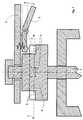
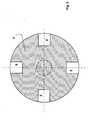
Selon une première variante, la vanne comprend une pièced'accouplement (4) concentrique à l'axe de rotation, dont la position détermine demanière univoque la position du dispositif d'obturation (1), et le dispositif desécurité comprend un levier de sécurité (2) capable de se déplacerapproximativement parallèlement à l'axe de rotation, de telle façon que l'organede commande (3) puisse pivoter indépendamment de la pièce d'accouplement (4)et donc sans provoquer le déplacement du dispositif d'obturation (1) lorsque lelevier de sécurité (2) n'est soumis à aucune force extérieure, alors que lepivotement de l'organe de commande (3) provoque le pivotement de la pièced'accouplement (4) et donc le déplacement du dispositif d'obturation (1) lorsquele levier de sécurité (2) est actionné par un opérateur.. A cette fin, la pièced'accouplement est généralement munie d'encoches dans lesquelles peuts'engager une pièce reliée au levier de sécurité (par exemple une extrémité dulevier) lorsque celui-ci est actionné. La pièce d'accouplement peut notammentêtre fixée concentriquement à l'axe de rotation ou en faire partie intégrante.According to a first variant, the valve comprises a partcoupling (4) concentric to the axis of rotation, the position of which determinesunequivocally the position of the shutter device (1), and the devicesafety includes a safety lever (2) capable of movingapproximately parallel to the axis of rotation, such that the membercontrol (3) can pivot independently of the coupling piece (4)and therefore without causing the displacement of the shutter device (1) when thesafety lever (2) is not subjected to any external force, while thepivoting of the control member (3) causes the part to pivotcoupling (4) and therefore the displacement of the closure device (1) whenthe safety lever (2) is actuated by an operator. To this end, the partcoupling is generally provided with notches in which canengage a part connected to the safety lever (for example one end of thelever) when it is activated. The coupling piece can in particularbe attached concentrically to the axis of rotation or be an integral part thereof.
Dans une forme d'exécution particulière de cette variante, l'organe decommande comprend au moins un levier de commande (3) substantiellement perpendiculaire à son axe de rotation, et le pivotement de l'organe de commande(3) provoque le pivotement de la pièce d'accouplement (4) et donc ledéplacement du dispositif d'obturation (1) lorsque les extrémités du levier decommande (3) et du levier de sécurité (2) sont rapprochées. Des moyens derappel tel qu'un ressort sont avantageusement utilisé pour maintenir écartées lesextrémités des leviers de commande et de sécurité en l'absence de sollicitationextérieure sur le levier de sécurité, permettant ainsi au levier de commande depivoter librement sans provoquer le déplacement du dispositif d'obturation.In a particular embodiment of this variant, thecontrol comprises at least one control lever (3) substantiallyperpendicular to its axis of rotation, and the pivoting of the control member(3) causes the coupling piece (4) to pivot and therefore themovement of the closure device (1) when the ends of thecontrol (3) and the safety lever (2) are brought together. Means ofreminder such as a spring are advantageously used to keep apart theends of the control and safety levers in the absence of stresson the safety lever, allowing the control lever topivot freely without causing the shutter to move.
Si un niveau de sécurité particulièrement élevé est nécessaire, il estpossible de recourir à des méthodes bien connues, par exemple en munissant lelevier de sécurité d'un dispositif de blocage, à clef ou autre.If a particularly high level of security is required, it iswell-known methods can be used, for example by providing thesafety lever of a blocking device, with key or other.
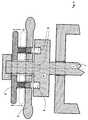
Selon une seconde variante, comprenant une pièce d'accouplement (4')concentrique audit axe de rotation, dont la position détermine de manièreunivoque la position dudit dispositif d'obturation (1), et dans laquelle le dispositifde sécurité comprend une plaque de sécurité (2) capable de se déplacerapproximativement parallèlement à l'axe de rotation, de telle façon que l'organede commande (3') puisse pivoter indépendamment de la pièce d'accouplement(4') et donc sans provoquer le déplacement du dispositif d'obturation (1) lorsquela plaque de sécurité (2') n'est soumise à aucune force extérieure, alors que lepivotement de l'organe de commande (3') provoque le pivotement de la pièced'accouplement (4') et donc le déplacement du dispositif d'obturation (1) lorsquela plaque de sécurité (2') est actionnée par un opérateur de façon à ce qu'elle serapproche de l'organe de commande (3'). A cette fin, la pièce d'accouplement estgénéralement de forme substantiellement cylindrique, et porte sur sa facesupérieure des encoches dans lesquelles peuvent s'engager des protubérancesfixées à la plaque de sécurité. Ici également, la pièce d'accouplement peutnotamment être fixée concentriquement à l'axe de rotation ou en faire partieintégrante.According to a second variant, comprising a coupling piece (4 ')concentric with said axis of rotation, the position of which determines sounequivocally the position of said shutter device (1), and in which the devicesecurity includes a security plate (2) capable of movingapproximately parallel to the axis of rotation, such that the membercontrol (3 ') can pivot independently of the coupling part(4 ') and therefore without causing the displacement of the closure device (1) whenthe safety plate (2 ') is not subjected to any external force, while thepivoting of the control member (3 ') causes the part to pivotcoupling (4 ') and therefore the displacement of the closure device (1) whenthe safety plate (2 ') is actuated by an operator so that it iscloser to the control member (3 '). To this end, the coupling piece isgenerally of substantially cylindrical shape, and bears on its faceupper notches into which protrusions can engageattached to the security plate. Here too, the coupling piece canin particular be fixed concentrically with the axis of rotation or form part of itintegral.
Des moyens de rappel tels qu'un ou plusieurs ressorts sontavantageusement utilisés pour maintenir écartées la plaque de sécurité et l'organede commande en l'absence de sollicitation extérieure sur la plaque de sécurité,permettant ainsi à l'organe de commande de pivoter librement sans provoquer ledéplacement du dispositif d'obturation.Return means such as one or more springs areadvantageously used to keep the safety plate and the member apartcontrol in the absence of external stress on the safety plate,thus allowing the control member to pivot freely without causing thedisplacement of the shutter device.
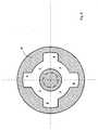
Selon une troisième variante, la vanne comprend une pièced'accouplement (4'') substantiellement cylindrique, concentrique à l'axe derotation, dont la position détermine de manière univoque la position du dispositif d'obturation (1), présentant une gorge circulaire (7) comportant desélargissements localisés (5), et le dispositif de sécurité comprend un levier desécurité (2'') capable de coulisser perpendiculairement à l'axe de rotation, munid'une protubérance (6) s'engageant dans la gorge (7) de telle façon que:
- lorsque le levier de sécurité (2'') n'est soumis à aucune force extérieure,la protubérance (6) peut circuler librement dans la gorge (7), et l'organe decommande (3'') peut donc pivoter indépendamment de la pièce d'accouplement(4''), sans provoquer le déplacement du dispositif d'obturation (1), alors que
- lorsque le lesier de sécurité (2'') est déplacé par un opérateur de façon àce qu'il s'éloigne de l'axe de rotation, la protubérance (6) s'engage dans unélargissement localisé (5) de la gorge (7), de telle sorte qu'un déplacement del'organe de l'organe de commande (3'') provoque le pivotement de la pièced'accouplement (4'') et donc le déplacement du dispositif d'obturation (1).
- when the safety lever (2 '') is not subjected to any external force, the protuberance (6) can circulate freely in the groove (7), and the control member (3 '') can therefore pivot independently of the coupling piece (4 ''), without causing the closure device (1) to move, while
- when the safety slider (2 '') is moved by an operator so that it moves away from the axis of rotation, the protuberance (6) engages in a localized enlargement (5) of the groove (7), so that a displacement of the member of the control member (3 '') causes the pivoting of the coupling piece (4 '') and therefore the displacement of the closure device ( 1).
Des moyens de rappel tels qu'un ou plusieurs ressorts sontavantageusement utilisés pour maintenir le levier de sécurité dans sa position laplus proche de l'axe de rotation en l'absence de sollicitation extérieure.Return means such as one or more springs areadvantageously used to maintain the safety lever in its position thecloser to the axis of rotation in the absence of external stress.
Cette troisième variante s'applique aussi bien aux cas où l'organe decommande comprend un levier qu'à ceux où l'organe de commande comprend unvolant.This third variant also applies to cases where thecontrol includes a lever only to those where the control member includes asteering wheel.
Les figures annexées illustrent, de façon non limitative, différentesvariantes de réalisation de la vanne de l'invention. Ces figures sontschématiques, et ne reprennent pas certains éléments secondaires tels que parexemple des joints d'étanchéité.
Claims (5)
Translated fromFrenchApplications Claiming Priority (2)
| Application Number | Priority Date | Filing Date | Title |
|---|---|---|---|
| FR9910767 | 1999-08-23 | ||
| FR9910767AFR2797932B1 (en) | 1999-08-23 | 1999-08-23 | MANUAL VALVE |
Publications (1)
| Publication Number | Publication Date |
|---|---|
| EP1079159A1true EP1079159A1 (en) | 2001-02-28 |
Family
ID=9549329
Family Applications (1)
| Application Number | Title | Priority Date | Filing Date |
|---|---|---|---|
| EP00202993AWithdrawnEP1079159A1 (en) | 1999-08-23 | 2000-08-18 | Manual valve |
Country Status (2)
| Country | Link |
|---|---|
| EP (1) | EP1079159A1 (en) |
| FR (1) | FR2797932B1 (en) |
Cited By (3)
| Publication number | Priority date | Publication date | Assignee | Title |
|---|---|---|---|---|
| EP1984665A4 (en)* | 2006-01-30 | 2011-04-06 | Smart Tap Company Pty Ltd | A disengageable spindle drive |
| EP3150888A1 (en)* | 2015-10-01 | 2017-04-05 | IMI Hydronic Engineering International SA | Actuator for controlling a valve |
| EP3150889A1 (en)* | 2015-10-01 | 2017-04-05 | IMI Hydronic Engineering International SA | An actuator for controlling a valve |
Families Citing this family (1)
| Publication number | Priority date | Publication date | Assignee | Title |
|---|---|---|---|---|
| US20240337328A1 (en)* | 2023-04-07 | 2024-10-10 | Hoffman Enclosures Inc. | Control Assembly for Valves |
Citations (8)
| Publication number | Priority date | Publication date | Assignee | Title |
|---|---|---|---|---|
| US1829365A (en)* | 1930-05-02 | 1931-10-27 | Charles F Meyer | Safety gas cock |
| US2797592A (en)* | 1952-09-03 | 1957-07-02 | Patent Button Company Of Tenne | Appliance knobs |
| DE1550390A1 (en)* | 1966-04-09 | 1969-07-10 | Boehmer Gmbh Maschf W | Shut-off valve for mining machines, especially travel valve for mining handles |
| FR2168653A5 (en)* | 1972-01-19 | 1973-08-31 | Monrocq Raymond | |
| DE3402103C1 (en)* | 1984-01-21 | 1985-03-28 | Heinrich Schulte & Sohn Gmbh & Co Kg, 5860 Iserlohn | Single-lever valve block |
| EP0450699A2 (en)* | 1990-04-04 | 1991-10-09 | GE Power Controls Italia S.p.a. | Enabling means for locking, by a padlock, hand control devices of electromechanical equipments |
| US5598724A (en) | 1995-12-26 | 1997-02-04 | Primeau; Mario | Butterfly valve safety lock |
| US5741003A (en)* | 1997-05-13 | 1998-04-21 | Emhart Inc. | Child-resistant handle |
- 1999
- 1999-08-23FRFR9910767Apatent/FR2797932B1/ennot_activeExpired - Fee Related
- 2000
- 2000-08-18EPEP00202993Apatent/EP1079159A1/ennot_activeWithdrawn
Patent Citations (8)
| Publication number | Priority date | Publication date | Assignee | Title |
|---|---|---|---|---|
| US1829365A (en)* | 1930-05-02 | 1931-10-27 | Charles F Meyer | Safety gas cock |
| US2797592A (en)* | 1952-09-03 | 1957-07-02 | Patent Button Company Of Tenne | Appliance knobs |
| DE1550390A1 (en)* | 1966-04-09 | 1969-07-10 | Boehmer Gmbh Maschf W | Shut-off valve for mining machines, especially travel valve for mining handles |
| FR2168653A5 (en)* | 1972-01-19 | 1973-08-31 | Monrocq Raymond | |
| DE3402103C1 (en)* | 1984-01-21 | 1985-03-28 | Heinrich Schulte & Sohn Gmbh & Co Kg, 5860 Iserlohn | Single-lever valve block |
| EP0450699A2 (en)* | 1990-04-04 | 1991-10-09 | GE Power Controls Italia S.p.a. | Enabling means for locking, by a padlock, hand control devices of electromechanical equipments |
| US5598724A (en) | 1995-12-26 | 1997-02-04 | Primeau; Mario | Butterfly valve safety lock |
| US5741003A (en)* | 1997-05-13 | 1998-04-21 | Emhart Inc. | Child-resistant handle |
Cited By (9)
| Publication number | Priority date | Publication date | Assignee | Title |
|---|---|---|---|---|
| EP1984665A4 (en)* | 2006-01-30 | 2011-04-06 | Smart Tap Company Pty Ltd | A disengageable spindle drive |
| AU2007209774B2 (en)* | 2006-01-30 | 2013-05-02 | Smart Tap Company Pty Limited | A disengageable spindle drive |
| EP3150888A1 (en)* | 2015-10-01 | 2017-04-05 | IMI Hydronic Engineering International SA | Actuator for controlling a valve |
| EP3150889A1 (en)* | 2015-10-01 | 2017-04-05 | IMI Hydronic Engineering International SA | An actuator for controlling a valve |
| WO2017054939A1 (en)* | 2015-10-01 | 2017-04-06 | Imi Hydronic Engineering International Sa | Actuator for controlling a valve |
| WO2017054940A1 (en)* | 2015-10-01 | 2017-04-06 | Imi Hydronic Engineering International Sa | An actuator for controlling a valve |
| CN108138987A (en)* | 2015-10-01 | 2018-06-08 | 埃迈海卓尼克工程国际有限责任公司 | For the actuator of control valve |
| CN108138987B (en)* | 2015-10-01 | 2020-01-17 | 埃迈海卓尼克工程国际有限责任公司 | Actuator for control valve |
| US10982784B2 (en) | 2015-10-01 | 2021-04-20 | Imi Hydronic Engineering International Sa | Actuator for controlling a valve |
Also Published As
| Publication number | Publication date |
|---|---|
| FR2797932A1 (en) | 2001-03-02 |
| FR2797932B1 (en) | 2001-10-12 |
Similar Documents
| Publication | Publication Date | Title |
|---|---|---|
| EP0743053B1 (en) | Safety device for ensuring the locking of a wheel hub, especially for wheelchairs | |
| EP0501866B1 (en) | Alignment pin and centering device for covering cap of a vessel using this kind of pin | |
| EP1526319B1 (en) | Liquid fuel filling device for vehicle | |
| EP0222628A1 (en) | Attachment device for a tubular element, in particular for a steering column of a vehicle | |
| FR2647873A1 (en) | VALVE FOR CONTROLLING THE FLOW OF A FLUID | |
| FR2679504A1 (en) | VEHICLE STEERING LOCK. | |
| EP1734552B1 (en) | Actuating device for an electrical switch device with rotational locking means | |
| EP0549498B1 (en) | Infusion manifold | |
| EP1079159A1 (en) | Manual valve | |
| EP2610691B1 (en) | Control device | |
| FR2898393A1 (en) | ANTIDEVIREUR SPRING. | |
| FR2713187A1 (en) | Steering column assembly, in particular for a motor vehicle. | |
| EP0253707A2 (en) | Security device preventing unscrewing for sliding part of a disc brake | |
| FR2848545A1 (en) | Cap screwing device, has moving unit rotating spindle to exercise eccentric drive force on spindle, and detection unit detecting applied force on spindle with respect to rotation of spindle | |
| EP2733267A2 (en) | Element for highway device, corresponding highway device and assembly | |
| EP2821570B1 (en) | Locking device for a door, in particular a sanitary room door, e.g. for a railway vehicle | |
| EP3296612A1 (en) | Valve for pressurised fluid | |
| FR2728494A1 (en) | Gas pipe crushing press | |
| EP1267110B1 (en) | Actuating device for a buried tap | |
| EP2192239A1 (en) | Device for coupling and uncoupling an equipment item or a tool to the jib of a civil engineering and/or handling machine. | |
| FR2739827A1 (en) | CONTROL DEVICE FOR A BICYCLE BRAKE, COMPRISING A DEVICE FOR LIMITING THE BRAKING FORCE | |
| FR2585440A1 (en) | Device for controlling a butterfly valve | |
| EP1036960B1 (en) | Device for mounting and dismantling a transmission cable connecting a gearshift lever to a security bolt in a motor vehicle gearbox | |
| FR2637248A1 (en) | Device for clamping a hub in a fork, particularly for a bicycle | |
| EP3486507A1 (en) | Mating tip of a cable for controlling a gearbox with a ball joint |
Legal Events
| Date | Code | Title | Description |
|---|---|---|---|
| PUAI | Public reference made under article 153(3) epc to a published international application that has entered the european phase | Free format text:ORIGINAL CODE: 0009012 | |
| AK | Designated contracting states | Kind code of ref document:A1 Designated state(s):AT BE CH CY DE DK ES FI FR GB GR IE IT LI LU MC NL PT SE | |
| AX | Request for extension of the european patent | Free format text:AL;LT;LV;MK;RO;SI | |
| 17P | Request for examination filed | Effective date:20010828 | |
| AKX | Designation fees paid | Free format text:AT BE CH CY DE DK ES FI FR GB GR IE IT LI LU MC NL PT SE | |
| 17Q | First examination report despatched | Effective date:20031210 | |
| STAA | Information on the status of an ep patent application or granted ep patent | Free format text:STATUS: THE APPLICATION IS DEEMED TO BE WITHDRAWN | |
| 18D | Application deemed to be withdrawn | Effective date:20040421 |