EP1078705B1 - Method for cutting profiled film sheets - Google Patents
Method for cutting profiled film sheetsDownload PDFInfo
- Publication number
- EP1078705B1 EP1078705B1EP00810664AEP00810664AEP1078705B1EP 1078705 B1EP1078705 B1EP 1078705B1EP 00810664 AEP00810664 AEP 00810664AEP 00810664 AEP00810664 AEP 00810664AEP 1078705 B1EP1078705 B1EP 1078705B1
- Authority
- EP
- European Patent Office
- Prior art keywords
- foil
- parting
- profiled
- accordance
- gap
- Prior art date
- Legal status (The legal status is an assumption and is not a legal conclusion. Google has not performed a legal analysis and makes no representation as to the accuracy of the status listed.)
- Expired - Lifetime
Links
- 238000000034methodMethods0.000titleclaimsabstractdescription19
- 239000011888foilSubstances0.000claimsabstractdescription47
- 239000000463materialSubstances0.000claimsabstractdescription18
- 238000005299abrasionMethods0.000claimsabstractdescription5
- 230000002093peripheral effectEffects0.000claimsdescription2
- 238000005192partitionMethods0.000claims2
- 229910001092metal group alloyInorganic materials0.000claims1
- 238000007789sealingMethods0.000claims1
- 239000002184metalSubstances0.000description9
- 229910052751metalInorganic materials0.000description9
- 238000000926separation methodMethods0.000description8
- 230000000737periodic effectEffects0.000description3
- 238000012856packingMethods0.000description2
- 238000007493shaping processMethods0.000description2
- 239000003086colorantSubstances0.000description1
- 230000013228contact guidanceEffects0.000description1
- 230000001419dependent effectEffects0.000description1
- 238000009434installationMethods0.000description1
- 238000002844meltingMethods0.000description1
- 230000008018meltingEffects0.000description1
- 150000002739metalsChemical class0.000description1
- 238000000465mouldingMethods0.000description1
- 239000002245particleSubstances0.000description1
- 239000004033plasticSubstances0.000description1
- 239000002985plastic filmSubstances0.000description1
- 229920006255plastic filmPolymers0.000description1
Images


Classifications
- B—PERFORMING OPERATIONS; TRANSPORTING
- B23—MACHINE TOOLS; METAL-WORKING NOT OTHERWISE PROVIDED FOR
- B23D—PLANING; SLOTTING; SHEARING; BROACHING; SAWING; FILING; SCRAPING; LIKE OPERATIONS FOR WORKING METAL BY REMOVING MATERIAL, NOT OTHERWISE PROVIDED FOR
- B23D45/00—Sawing machines or sawing devices with circular saw blades or with friction saw discs
- B23D45/26—Sawing machines or sawing devices with circular saw blades or with friction saw discs with high-speed cutting discs, performing the cut by frictional heat melting the material
Definitions
- the inventionrelates to a method for dividing profiled films as well a facility for performing the Process.
- Films with a zigzag profilingare considered elementary Structural elements used for ordered packing of separation columns, in where these films are arranged side by side in vertical layers.
- Such profiled filmsare for example by means of a Pleating process made from a flat metal strip, where straight folding edges result.
- the metal stripis a thin foil with a thickness, for example, 0.1 mm.
- this slideshows already before pleating a fine structuring in the form of a grooving on.
- the pleated metal stripis cut into pieces whose lengths through the installation conditions are given in the separation column. Because the fold edges are straight, results in the division of a separating edge, the one has periodic profile. Thanks to this fact, the metal strips be cut to any length by means of a shear.
- the object of the inventionis to provide an alternative to a shear molding means create a cutting of profiled metal strips for which the separation edges have no periodic profiles. This task is defined by the method defined in claim 1 and the system according to Claim 7 solved.
- the process for cutting a profiled filmis with a rotating Separation film performed a flat surface with circular periphery forms.
- the release filmis around the circular center and in through the area spanned plane, the film plane, rotates. Under Run a Relative movement, the periphery in contact with the profiled film brought. It is removed by abrasion material and a separation gap generated in the profiled foil. It is material largely only by the profiled foil removed.
- the release filmcan - compared with the metal strips that make up the be produced profiled films, - be relatively thick. She can be a thin one Sheet metal that is several tenths of a millimeter thick. While the profiled Foil can be made of a plastic, the choice of material in the Release film limited to metals for practical reasons. When pleated Plastic films, the release film with advantage thinner than to be divided Foil.
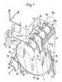
- Fig. 1shows the simplified release disk 1 shown as a circular disk with the Center 10 and the periphery 11.
- the arrows 1a and 1bindicate a rotation of the release film 1 about the center 10 and a translational movement of the center 10 in the direction of the y-axis.
- the Film levelnamely the plane spanned by the release film 1 level is parallel to the y and z axes.
- An upper circle segment 1s of the release film 1becomes within a gap 20 of a device 2 out.
- Between the top 35 of a support plate 3, which is only partially shown, and the Guide device 2 and a fixing bar 40is a profiled film. 5 inserted.
- the inventive dicing processis in Fig. 1 to a Timing shown, at which a material removal takes place in point 15.
- a there released abrasion, d. H. the worn materialis indicated by arrows 6.
- the profiled sheet 5is for a channel 50 containing layer one Column packing provided. Edge lines 52 lie on two parallel Surfaces 53a and 53b.
- the layer formed by the film 5has a Side edge 54, which extends in the direction of the x-axis. In a border zone at the side edge 54, the channels 50 have curved sections 50 '. Because of this shaping of the edge zone, it is not possible to form shear Use to cut the film 5 at any point.
- the rotating release film 1is in a Waiting position outside the guide device 2 withdrawn.
- the Device 2 and the Fixierbalken 40are raised slightly, so that the removed piece of film removed and a new piece of film 5 in the x direction (Arrow 5a) can be pushed.
- the Slide 5 fixed again with the bar 40the one at its bottom rubber-elastic layer 45 carries.
- the visible end 21 of the guide gap 20is formed with a steadily widening gap width, so that thanks this shaping the release film in a further generating a Separation gap 51 can enter without contact in the guide gap 20.
- Fig. 2shows a part of a system with which the inventive method is feasible.
- the release film 1is detachable between two clamping plates Attached 12a and 12b.
- the one clamping plate 12ais not one shown drive shaft of a motor 70 fixedly connected; the other Clamping plate 12b can be replaced by loosening the release film 1 remove a screw ring 14.
- the clamping plates 12a and 12bare elastically deformable and wear on the clamping surfaces annular Elevations 13, which generate particularly high local clamping forces to let.
- the clamping force between the two clamping plates 12a and 12bcan continue through additional, not shown connecting screws be strengthened.
- the Motor 70is an advantage asynchronous motor, a shaft except for one Speed of around 9000 rpm.
- the radius of the circular release film 1is a value between 100 and 500 mm.
- the rotation of the release film 1is empirically on the Choice of materials matched so that - see Fig. 3 - the Surface points of the periphery 11 with a sufficiently high Move speed v.
- the temperature of the profiled foil 5increases Abrasion point 15 to high values, which are close to the melting point, the material of the film 5 has, may lie. In these circumstances be in the forming separating gap 51 particles 6 'from the Sheared contact surface and transported away from this (arrow 6).
- the sufficiently high speed vcreates a sharp-edged separation gap 51, on the flanks of virtually no changes - for example Tarnish colors - are detectable.
- the speed vis minimized as much as possible set so that a minimal material removal on the release film. 1 results.
- the peripheral speed vgreater than about 50 m / s.
- the release film 1is guided on the periphery 11 in the region of a segment-shaped part 1s contactless air layers between the edges of the gap 20 and the surfaces of the part 1s. It is selected a width of the gap 20, which is about 0.1 to 0.5 mm, preferably 0.15 to 0.25 mm greater than the thickness of the release film 1.
- Arrows 16, 16 'and 16"represent the air that is entrained by the surface of the rotating film 1. The air flow is strongly decelerated in the gap 2. This produces p L and p R in the region of the segment-shaped part 1s, which are larger when the ambient pressure p is 0.
- the plant 7 shown in FIG. 6comprises the following components: a Drive motor 70 for the release film 5; one connected to the drive 70 Linear motor 71, with which the relative movement 1b - see Fig. 1 - executable is; a clamping device 4 for the profiled film 5, with this during the dividing is fixable; a conveyor 72 for the profiled foil (Promotion in the direction of arrow 5a); Furthermore, a control device 9 for an automatic operation of the system 7.
- the clamping device 4includes a linear motor, not shown for a Lifting movement, with a state change of the clamping device between an open and a closed state can be produced. It contains also the guide device 2 (see Fig. 2).
- the control device 9is via control lines 91, 92 and 94 with the components 71, 72 and 4, respectively connected.
- the release film 1is together with its drive 70 in a casing. 8 arranged.
- a suction device 80 for abraded Materialconnected via a hose 82 to the casing 8. It is a seal of the casing 8 in the form of brush 81 is provided.
- the inventive methodis particularly suitable to a profiled To divide film 5, which by forming from a plan, metallic strip of material is made, with ridge lines 52 of the Profiling on two mutually parallel planes 53a and 53b - see Fig. 1st - are arranged.
Landscapes
- Engineering & Computer Science (AREA)
- Mechanical Engineering (AREA)
- Processing And Handling Of Plastics And Other Materials For Molding In General (AREA)
- Processing Of Solid Wastes (AREA)
- Sheets, Magazines, And Separation Thereof (AREA)
- Finish Polishing, Edge Sharpening, And Grinding By Specific Grinding Devices (AREA)
- Folding Of Thin Sheet-Like Materials, Special Discharging Devices, And Others (AREA)
- Manufacture Of Motors, Generators (AREA)
- Feeding Of Articles To Conveyors (AREA)
- Magnetic Heads (AREA)
- Milling Processes (AREA)
- Treatment Of Fiber Materials (AREA)
- Perforating, Stamping-Out Or Severing By Means Other Than Cutting (AREA)
- Separation, Recovery Or Treatment Of Waste Materials Containing Plastics (AREA)
- Separation Using Semi-Permeable Membranes (AREA)
- Combined Means For Separation Of Solids (AREA)
Abstract
Description
Translated fromGermanDie Erfindung betrifft ein Verfahren zum Zerteilen von profilierten Folien sowieeine Anlage zum Durchführen desVerfahrens.The invention relates to a method for dividing profiled films as wella facility for performing theProcess.
Folien mit einer zickzackförmigen Profilierung werden als elementareBauelemente für geordnete Packungen von Trennkolonnen verwendet, indenen diese Folien in vertikalen Lagen nebeneinander angeordnet sind.Solche profilierten Folien werden beispielsweise mittels einesPlissierverfahrens aus einem planen Metallstreifen hergestellt, wobei sichgeradlinige Faltkanten ergeben. Der Metallstreifen ist eine dünne Folie miteiner Dicke, die beispielsweise 0.1 mm beträgt. In der Regel weist diese Foliebereits vor dem Plissieren eine feine Strukturierung in Form einer Rillierungauf. Der plissierte Metallstreifen wird in Stücke zerteilt, deren Längen durchdie Einbauverhältnisse in der Trennkolonne gegeben sind. Da die Faltkantengeradlinig sind, ergibt sich bei der Zerteilung eine Trennkante, die einperiodisches Profil aufweist. Dank dieser Tatsache können die Metallstreifenmittels einer Formschere auf beliebige Längen zerschnitten werden.Films with a zigzag profiling are considered elementaryStructural elements used for ordered packing of separation columns, inwhere these films are arranged side by side in vertical layers.Such profiled films are for example by means of aPleating process made from a flat metal strip, wherestraight folding edges result. The metal strip is a thin foil witha thickness, for example, 0.1 mm. In general, this slide showsalready before pleating a fine structuring in the form of a groovingon. The pleated metal strip is cut into pieces whose lengths throughthe installation conditions are given in the separation column. Because the fold edgesare straight, results in the division of a separating edge, the onehas periodic profile. Thanks to this fact, the metal stripsbe cut to any length by means of a shear.
Während bei einer geordneten Packung, die aus solchen plissierten Folienaufgebaut ist, geradlinige Strömungskanäle - in der Regel in Form einerKreuzkanalstruktur - vorliegen, sind bei einer abgewandelten Form diesesPackungstyps die Kanäle nicht mehr geradlinig ausgebildet. Dabei sind dieFolien der Lagen so profiliert, dass in Randzonen die Kanalkanten gekrümmtsind. Metallstreifen, die mit einer solchen Profilierung versehen sind, lassen sich nicht mehr mittels einer Formschere in beliebig lange Stücke schneiden.Dies ist eine Folge davon, dass das Profil der Trennkante nicht mehrperiodisch ist.While with an orderly pack, those made from such pleated slidesis constructed, straight-line flow channels - usually in the form of aCross-channel structure - present, are in a modified form thisPack type, the channels are no longer rectilinear. Here are theSheets of the layers profiled in such a way that the edges of the edges of the channels are curvedare. Metal strips that are provided with such a profiling, letno longer cut into arbitrarily long pieces by means of a shear.This is a consequence of the fact that the profile of the cutting edge is no longeris periodic.
Aufgabe der Erfindung ist es, ein zu einer Formschere alternatives Mittel zuschaffen, das ein Zerteilen von profilierten Metallstreifen ermöglicht, fürwelche die Trennkanten keine periodischen Profile aufweisen. Diese Aufgabewird durch das im Anspruch 1 definierte Verfahren und die Anlage gemässAnspruch 7 gelöst.The object of the invention is to provide an alternative to a shear molding meanscreate a cutting of profiled metal strips forwhich the separation edges have no periodic profiles. This taskis defined by the method defined in
Das Verfahren zum Zerteilen einer profilierten Folie wird mit einer rotierendenTrennfolie durchgeführt, die eine ebene Fläche mit kreisförmiger Peripheriebildet. Die Trennfolie wird um das Kreiszentrum und in der durch die Flächeaufgespannten Ebene, der Folienebene, rotiert. Unter Ausführen einerRelativbewegung wird die Peripherie mit der profilierten Folie in Kontaktgebracht. Dabei wird durch Abreiben Material abgetragen und ein Trennspaltin der profilierten Folie erzeugt. Es wird Material weitgehend nur von derprofilierten Folie abgetragen.The process for cutting a profiled film is with a rotatingSeparation film performed a flat surface with circular peripheryforms. The release film is around the circular center and in through the areaspanned plane, the film plane, rotates. Under Run aRelative movement, the periphery in contact with the profiled filmbrought. It is removed by abrasion material and a separation gapgenerated in the profiled foil. It is material largely only by theprofiled foil removed.
Die Trennfolie kann - verglichen mit den Metallstreifen, aus denen dieprofilierten Folien hergestellt werden, - relativ dick sein. Sie kann ein dünnesBlech sein, das mehrere Zehntel Millimeter dick ist. Während die profilierteFolie aus einem Kunststoff hergestellt sein kann, ist die Materialwahl bei derTrennfolie aus praktischen Gründen auf Metalle beschränkt. Bei plissiertenKunststofffolien ist die Trennfolie mit Vorteil dünner als die zu zerteilendeFolie.The release film can - compared with the metal strips that make up thebe produced profiled films, - be relatively thick. She can be a thin oneSheet metal that is several tenths of a millimeter thick. While the profiledFoil can be made of a plastic, the choice of material in theRelease film limited to metals for practical reasons. When pleatedPlastic films, the release film with advantage thinner than to be dividedFoil.
Die abhängigen Ansprüche 2 bis 6 und 8 bis 10 betreffen vorteilhafteAusführungsformen des erfindungsgemässen Verfahrens bzw. dererfindungsgemässen Anlage.The dependent claims 2 to 6 and 8 to 10 relate to advantageousEmbodiments of the inventive method or theinventive plant.
Nachfolgend wird die Erfindung anhand der Zeichnungen erläutert. Es zeigen:
- Fig. 1
- eine von unten gesehen und vereinfacht dargestellte Trennfolie,mit der erfindungsgemäss eine profilierte Folie zerteilt wird,
- Fig. 2
- Details zu einer erfindungsgemässen Anlage,
- Fig. 3
- eine Illustration zum Abreibprozess beim Zerteilen derprofilierten Folie,
- Fig. 4
- ausschnittsweise eine Seitenansicht der rotierenden Trennfoliemit einer Darstellung von mitgeführter Luft,
- Fig. 5
- eine der Fig. 4 entsprechende Ansicht, mit Blick in Richtung derRotationsebene, wobei Fig. 4 eine Seitenansicht nach der LinieIV - IV ist, und
- Fig. 6
- eine schematisch dargestellte Anlage gemäss der Erfindung.
- Fig. 1
- a separating film, seen from below and simplified, with which according to the invention a profiled foil is cut,
- Fig. 2
- Details of a plant according to the invention,
- Fig. 3
- an illustration of the Abreibprozess when dividing the profiled film,
- Fig. 4
- a detail of a side view of the rotating separating film with a representation of entrained air,
- Fig. 5
- a view corresponding to FIG. 4, looking in the direction of the plane of rotation, wherein FIG. 4 is a side view along the line IV - IV, and
- Fig. 6
- a schematically illustrated system according to the invention.
Fig. 1 zeigt die vereinfacht als Kreisscheibe dargestellte Trennfolie 1 mit demZentrum 10 und der Peripherie 11. Zur besseren Orientierung sind x-, y- undz-Achsen eines orthogonalen Koordinatensystems angegeben. Die Pfeile 1aund 1b geben eine Rotation der Trennfolie 1 um das Zentrum 10 bzw. einetranslatorische Bewegung des Zentrums 10 in Richtung der y-Achse an. DieFolienebene, nämlich die durch die Trennfolie 1 aufgespannte Ebene, istparallel zur y- und z-Achse. Ein oberes Kreissegment 1s der Trennfolie 1 wirdinnerhalb eines Spalts 20 einer Einrichtung 2 geführt. Zwischen der Oberseite35 einer Auflageplatte 3, die nur teilweise dargestellt ist, und derFührungseinrichtung 2 sowie einem Fixierbalken 40 ist eine profilierte Folie 5eingelegt. Der erfindungsgemässe Zerteilvorgang ist in Fig. 1 zu einemZeitpunkt dargestellt, zu dem ein Materialabtrag im Punkt 15 erfolgt. Einbereits hergestellter Trennspalt 51 endet momentan in diesem Punkt 15 ander Peripherie 11 der Trennfolie 1. Ein dort freigesetzter Abrieb, d. h. dasabgetragende Material, ist mit Pfeilen 6 angedeutet.Fig. 1 shows the
Die profilierte Folie 5 ist für eine Kanäle 50 enthaltende Lage einerKolonnenpackung vorgesehen. Kantenlinien 52 liegen auf zwei parallelenFlächen 53a und 53b. Die durch die Folie 5 gebildete Lage hat einenSeitenrand 54, der sich in Richtung der x-Achse erstreckt. In einer Randzoneam Seitenrand 54 haben die Kanäle 50 gekrümmte Teilstücke 50'. Wegen dieser Formgebung der Randzone ist es nicht möglich, eine Formschere zuverwenden, um die Folie 5 an einer beliebigen Stelle zu zerschneiden.The profiled
Nach dem Zerteilen der Folie 5 wird die rotierende Trennfolie 1 in eineWartestellung ausserhalb der Führungseinrichtung 2 zurückgezogen. DieEinrichtung 2 und der Fixierbalken 40 werden etwas angehoben, so dass dasabgetrennte Folienstück entfernt und ein neues Stück der Folie 5 in x-Richtung(Pfeil 5a) nachgeschoben werden kann. Anschliessend wird dieFolie 5 wieder mit dem Balken 40 fixiert, der an seiner Unterseite einegummielastische Schicht 45 trägt. Das sichtbare Ende 21 des Führungspalts20 ist mit einer sich stetig erweiternden Spaltbreite ausgebildet, so dass dankdieser Formgebung die Trennfolie bei einem weiteren Erzeugen einesTrennspalts 51 berührungslos in den Führungspalt 20 eintreten kann.After dividing the
Fig. 2 zeigt einen Teil einer Anlage, mit der das erfindungsgemässe Verfahrendurchführbar ist. Die Trennfolie 1 ist lösbar zwischen zwei Einspanntellern12a und 12b befestigt. Der eine Einspannteller 12a ist mit einer nichtdargestellten Antriebswelle eines Motors 70 fest verbunden; der andereEinspannteller 12b lässt sich zum Auswechseln der Trennfolie 1 durch Löseneines Schraubrings 14 entfernen. Die Einspannteller 12a und 12b sindelastisch verformbar und tragen an den Klemmflächen ringförmigeErhebungen 13, mit denen sich besonders hohe lokale Klemmkräfte erzeugenlassen. Die Klemmkraft zwischen den beiden Einspanntellern 12a und 12bkann durch zusätzliche, nicht abgebildete Verbindungsschrauben weiterverstärkt werden.Fig. 2 shows a part of a system with which the inventive methodis feasible. The
Zwischen der Auflageplatte 3 und einer Klemmeinrichtung 4 ist die inRichtung des Pfeils 5a eingeschobene profilierte Folie 5 fixiert; die rotierendeTrennfolie 1 erzeugt in der Folie 5 den Trennspalt 51. Auf und ab bewegbareTeile der Klemmeinrichtung 4 sind zwei Fixierbalken 40 mit weichenAnpressschichten 45 und die Einrichtung 2 mit dem Führungsspalt 20. DerMotor 70 ist mit Vorteil ein Asynchronmotor, der eine Welle bis auf eineDrehzahl von rund 9000 Umdrehungen pro Minute antreiben kann.Between the
Für den Radius der kreisförmigen Trennfolie 1 wird ein Wert zwischen 100und 500 mm gewählt. Die Rotation der Trennfolie 1 wird empirisch auf die Wahl der Materialien abgestimmt, so dass - siehe Fig. 3 - dieOberflächenpunkte der Peripherie 11 sich mit einer ausreichend hohenGeschwindigkeit v bewegen. Die Temperatur der profilierten Folie 5 steigt ander Abreibstelle 15 auf hohe Werte an, die in der Nähe des Schmelzpunkts,den das Material der Folie 5 hat, liegen können. Bei diesen Verhältnissenwerden in dem sich bildenden Trennspalt 51 Partikelchen 6' aus derKontaktfläche abgeschert und von dieser wegbefördert (Pfeil 6). Bei derausreichend hohen Geschwindigkeit v entsteht ein scharfkantiger Trennspalt51, an dessen Flanken praktisch keine Veränderungen - beispielsweiseAnlauffarben - feststellbar sind. Die Geschwindigkeit v wird möglichst minimaleingestellt, so dass sich ein minimaler Materialabtrag an der Trennfolie 1ergibt. Erfahrungsgemäss ist bei einer Trennfolie 1 und einer profilierten Folie5, die beide metallisch sind und für die die Dicken 0.3 mm bzw. 0.1 mmbetragen, die Peripheriegeschwindigkeit v grösser als rund 50 m/s.For the radius of the
Im Führungsspalt 20 - siehe Figuren 4 und 5 - wird die Trennfolie 1 an derPeripherie 11 im Bereich eines segmentförmigen Teils 1s berührungslos aufLuftschichten zwischen den Flanken des Spalts 20 und den Oberflächen desTeils 1s geführt. Es wird eine Breite des Spalts 20 gewählt, die rund 0.1 bis0.5 mm, vorzugsweise 0.15 bis 0.25 mm grösser als die Dicke der Trennfolie1 ist. Pfeile 16, 16' und 16" stellen die Luft dar, die von der Oberfläche derrotierenden Folie 1 mitgerissen wird. Die Luftströmung wird im Spalt 2 starkabgebremst. Es entstehen Dücke pL und pR im Bereich des segmentförmigenTeils 1s, die grösser als der Umgebungsdruck p0 sind. Auf der Seite dessegmentförmigen Teils 1s, auf der die Luftschicht schmaler ist, ergibt sicheine grössere Abbremsung der mitgeführten Luftströmung, die mit einemgrösseren Druckanstieg verbunden ist (Fig. 5: pL > pR). Durch die soentstehenden Druckdifferenzen zwischen den seitlichen Luftschichten dessegmentförmigen Teils 1s ergibt sich eine Zentrierung der Folie 1 im Spalt 20und somit eine berührungsfreie Führung durch diesen Spalt 20.In the guide gap 20 - see Figures 4 and 5 - the
Die in Fig. 6 dargestellte Anlage 7 umfasst folgende Komponenten: einenAntriebsmotor 70 für die Trennfolie 5; einen mit dem Antrieb 70 verbundenenLinearmotor 71, mit dem die Relativbewegung 1b - siehe Fig. 1 - ausführbarist; eine Klemmeinrichtung 4 für die profilierte Folie 5, mit der diese währenddes Zerteilens fixierbar ist; eine Fördervorrichtung 72 für die profilierte Folie (Förderung in Richtung des Pfeils 5a); ferner eine Steuereinrichtung 9 füreinen automatischen Betrieb der Anlage 7.The
Die Klemmeinrichtung 4 enthält einen nicht dargestellten Linearmotor für eineHubbewegung, mit der ein Zustandswechsel der Klemmeinrichtung zwischeneinem offenen und einem geschlossenen Zustand herstellbar ist. Sie enthältauch die Führungseinrichtung 2 (siehe Fig. 2). Die Steuereinrichtung 9 istüber Steuerleitungen 91, 92 und 94 mit den Komponenten 71, 72 bzw. 4verbunden.The
Die Trennfolie 1 ist zusammen mit ihrem Antrieb 70 in einer Verschalung 8angeordnet. Mit Vorteil ist eine Absaugeinrichtung 80 für abgeriebenesMaterial über einen Schlauch 82 an der Verschalung 8 angeschlossen. Es isteine Abdichtung der Verschalung 8 in Form von Bürsten 81 vorgesehen.The
Das erfindungsgemässe Verfahren ist besonders geeignet, um eine profilierteFolie 5 zu zerteilen, die durch eine Umformung aus einem planen,metallischen Materialstreifen hergestellt ist, wobei Kammlinien 52 derProfilierung auf zwei zueinander parallelen Ebenen 53a und 53b - siehe Fig. 1- angeordnet sind.The inventive method is particularly suitable to a profiledTo divide
Claims (10)
- A method for dividing up a profiled foil (5) with a rotating separatingfoil (1) which forms a planar surface with a circular periphery(11) and a circle centre, said parting foil being rotated (1a)about the circle center (10) and in the plane (10a), the foil plane,which is spanned by the planar surface, with the periphery beingbrought into contact (15) with the profiled foil by the execution ofa relative movement (1b) in such a manner that material (6) isremoved by abrasion and a partition gap (51) is produced in theprofiled foil and material is largely removed from the profiled foilonly.
- A method in accordance with claim 1,characterized in that theprofiled foil (5) and the parting foil (1) consist of metallic alloysand the thickness of the parting foil (1) is chosen to be greaterthan that of the profiled foil (5).
- A method in accordance with claim 1 or claim 2,characterized inthat the profiled foil (5) is fixed in a clamping device (4, 40) duringthe dividing up and the rotating parting foil (1) is moved in the foilplane (10a) in a translatory manner.
- A method in accordance with any one of the claims 1 to 3,characterizedin that the parting foil (1) is guided at its periphery (11,1s) without contact on air layers in a guiding gap (2), with a gapwidth being chosen which is about 0.1 to 0.5 mm, preferably 0.15to 0.25 mm greater than the thickness of the parting foil.
- A method in accordance with any one of the claims 1 to 4,characterizedin that a value between 100 and 500 mm is chosen forthe radius of the parting foil (1); andin that the rotation (1a) ofthe parting foil is empirically matched to the choice of the materialsso that the surface points of the periphery (11) move with asufficiently high velocity (v), for which, on the one hand, a sharpedged partition gap (51) arises in the profiled foil (5) and, on theother hand, a minimum material removal results at the partingfoil (1), with in accordance with experience the peripheral velocity(v) being greater than about 50 m/s for a parting foil (1) and aprofiled foil (5) which are metallic and which have thicknesses of0.3 mm and 0.1 mm respectively.
- A method in accordance with any one of the claims 1 to 5,characterizedin that the profiled foil (5) is manufactured by formingfrom a planar material strip; andin that ridge lines (52) of theprofile lie on two mutually parallel planes (53a, 53b).
- An apparatus (7) for carrying out the method in accordance withany one of the claims 1 to 5, comprising the following components:a drive (70) for the parting foil (1), in particular an asynchronousmotor;a linear motor which is connected to the drive and by means ofwhich the relative movement (1b) between the two foils (1, 5) canbe accomplished;a clamping device (4) for the profiled foil (5) by means of whichthis foil can be fixed during the dividing up;a linear motor for a lifting movement by means of which a change of state of the clamping device (4) between an open state and aclosed state can be produced;a guiding gap (20) for the parting foil (1) which is part of theclamping device (4);a conveying device (72) for the profiled foil (5); furthermorea control device (9) for an automatic operation of the apparatus(7).
- An apparatus in accordance with claim 7,characterized in that awaiting position for the parting foil (1) is provided outside theclamping device (4); andin that at least one end (21) of the guidinggap (20) is formed with a continuously widening gap width sothat due to this shape the parting foil can enter into the guidinggap largely without contact.
- An apparatus in accordance with claim 7 or claim 8,characterizedin that the parting foil (1) is releasably secured between twoclamping plates (12a, 12b), with the one clamping plate (12a) beingfirmly connected to a drive shaft and the other clamping plate(12b) being removable for replacing the parting foil.
- An apparatus in accordance with any one of the claims 7 to 9,characterized in that the parting foil (1) is arranged together withits drive (70) in a casing (8), with a sealing (81) of the casing beingprovided which is in particular produced through brushes; andinthat a suction device (80) for abraded material (6, 6') is advantageouslyconnected to the casing.
Priority Applications (1)
| Application Number | Priority Date | Filing Date | Title |
|---|---|---|---|
| EP00810664AEP1078705B1 (en) | 1999-08-25 | 2000-07-26 | Method for cutting profiled film sheets |
Applications Claiming Priority (3)
| Application Number | Priority Date | Filing Date | Title |
|---|---|---|---|
| EP99810761 | 1999-08-25 | ||
| EP99810761 | 1999-08-25 | ||
| EP00810664AEP1078705B1 (en) | 1999-08-25 | 2000-07-26 | Method for cutting profiled film sheets |
Publications (2)
| Publication Number | Publication Date |
|---|---|
| EP1078705A1 EP1078705A1 (en) | 2001-02-28 |
| EP1078705B1true EP1078705B1 (en) | 2005-01-26 |
Family
ID=8242993
Family Applications (1)
| Application Number | Title | Priority Date | Filing Date |
|---|---|---|---|
| EP00810664AExpired - LifetimeEP1078705B1 (en) | 1999-08-25 | 2000-07-26 | Method for cutting profiled film sheets |
Country Status (16)
| Country | Link |
|---|---|
| US (1) | US6500048B1 (en) |
| EP (1) | EP1078705B1 (en) |
| JP (1) | JP4515608B2 (en) |
| CN (1) | CN1204993C (en) |
| AT (1) | ATE287776T1 (en) |
| AU (1) | AU776624B2 (en) |
| BR (1) | BR0003776A (en) |
| CA (1) | CA2313728C (en) |
| CZ (1) | CZ302859B6 (en) |
| DE (1) | DE50009333D1 (en) |
| ES (1) | ES2235815T3 (en) |
| MX (1) | MXPA00008242A (en) |
| PL (1) | PL193383B1 (en) |
| RU (1) | RU2213647C2 (en) |
| SG (1) | SG97907A1 (en) |
| TW (1) | TW572802B (en) |
Families Citing this family (14)
| Publication number | Priority date | Publication date | Assignee | Title |
|---|---|---|---|---|
| US8499670B2 (en) | 2001-07-23 | 2013-08-06 | Newell Window Furnishings, Inc. | Modular blind cutting center |
| US6604443B2 (en)* | 2001-07-23 | 2003-08-12 | Newell Window Furnishings, Inc. | Blind and shade cutting center |
| US7810418B2 (en) | 2003-03-03 | 2010-10-12 | Newell Window Furnishings, Inc. | Automatically configurable blind cutting center |
| US7036412B2 (en)* | 2003-03-03 | 2006-05-02 | Newell Window Furnishings, Inc. | Blind cutting center with detachable vacuum bag |
| US7178439B2 (en) | 2003-03-03 | 2007-02-20 | Newell Window Furnishings, Inc. | Blind cutting center |
| US8256333B2 (en) | 2007-07-31 | 2012-09-04 | Newell Window Furnishings, Inc. | Window covering sizing method and apparatus |
| US9427813B2 (en) | 2007-07-31 | 2016-08-30 | Newell Window Furnishing, Inc. | Window covering sizing method and apparatus |
| US7987754B2 (en) | 2007-07-31 | 2011-08-02 | Newell Window Furnishings, Inc. | Window covering sizing method and apparatus |
| US8322260B2 (en) | 2007-07-31 | 2012-12-04 | Newell Window Furnishings, Inc. | Window covering sizing method and apparatus |
| US8839701B2 (en) | 2007-07-31 | 2014-09-23 | Newell Window Furnishings, Inc. | Window covering sizing method and apparatus |
| US8479925B2 (en) | 2010-07-19 | 2013-07-09 | Newell Window Furnishings, Inc. | Display system |
| US9266639B2 (en) | 2010-07-19 | 2016-02-23 | Newell Window Furnishings, Inc. | Blind packaging and methods of cutting window coverings |
| US9517501B2 (en) | 2011-07-21 | 2016-12-13 | Sulzer Chemtech Ag | Sheet forming tool and a method for the manufacture of a corrugated sheet |
| RU2499663C1 (en)* | 2012-03-14 | 2013-11-27 | Федеральное государственное бюджетное образовательное учреждение высшего профессионального образования "Московский государственный технологический университет "СТАНКИН" (ФГБОУ ВПО МГТУ "СТАНКИН") | Method of cutting ductile metals by high-strength thread |
Family Cites Families (21)
| Publication number | Priority date | Publication date | Assignee | Title |
|---|---|---|---|---|
| US3742798A (en)* | 1971-10-21 | 1973-07-03 | Owens Illinois Inc | Corrugated sheet cutoff length adjustment apparatus |
| FR2235751A1 (en)* | 1973-07-04 | 1975-01-31 | Rolls Royce | Friction type tool to make fine slit - uses special cooling fluid |
| US4018118A (en)* | 1974-11-25 | 1977-04-19 | Goff Edward W | High speed precision metal cutting saw assembly |
| FR2326270A1 (en)* | 1975-10-02 | 1977-04-29 | Europ Propulsion | TOOL HOLDER SPINDLE ASSEMBLY, ESPECIALLY FOR GRINDING MACHINE |
| IT1084145B (en)* | 1977-05-25 | 1985-05-25 | Gadani Carlo | ROTARY MOLD MACHINE FOR THE CONTINUOUS PRODUCTION OF ELEMENTS IN REINFORCED THERMOSETTING RESINS OR IN THERMOPLASTIC LAMINATE |
| JPS5924912A (en)* | 1982-07-29 | 1984-02-08 | Sugiyama Tekkosho:Kk | Method and apparatus for frictional cutting |
| DE3514169A1 (en) | 1985-04-19 | 1986-10-23 | Chr. Eisele Maschinenfabrik GmbH & Co KG, 7316 Köngen | SAWING MACHINE |
| US4771667A (en)* | 1986-09-02 | 1988-09-20 | Metl-Saw System Inc | Precision metal cutting saw and assembly |
| SU1590227A1 (en)* | 1988-10-10 | 1990-09-07 | Запорожский автомобильный завод "Коммунар" | Arrangement for transverse cutting of strip material |
| JPH0326279U (en)* | 1989-07-19 | 1991-03-18 | ||
| JP2763942B2 (en)* | 1989-12-08 | 1998-06-11 | 昭和電工株式会社 | Manufacturing method of silicon carbide sheet |
| US5165314A (en)* | 1990-07-24 | 1992-11-24 | Marquip, Inc. | Slitting shingled sheets |
| US5203761A (en)* | 1991-06-17 | 1993-04-20 | Sealed Air Corporation | Apparatus for fabricating dunnage material from continuous web material |
| US5327885A (en)* | 1991-10-08 | 1994-07-12 | Griffith James M | Combination catheter for invasive probe delivery and balloon dilation |
| JPH05301158A (en)* | 1992-04-23 | 1993-11-16 | Kitashiba Denki Kk | Amorphous metal foil cutting method |
| JPH068233A (en)* | 1992-06-29 | 1994-01-18 | Hitachi Ltd | High precision grinding and cutting device and grinding and cutting method using the same |
| JPH0724725A (en)* | 1993-07-07 | 1995-01-27 | Murata Mfg Co Ltd | Dicing saw and dicing blade |
| JPH0839429A (en)* | 1994-07-25 | 1996-02-13 | Disco Abrasive Syst Ltd | Cutting equipment |
| JPH09187815A (en)* | 1996-01-09 | 1997-07-22 | Olympus Optical Co Ltd | Under-liquid cutting method and device |
| JPH09272061A (en)* | 1996-04-05 | 1997-10-21 | Mitsubishi Materials Corp | Diamond blade excellent in durability |
| JPH11188636A (en)* | 1997-12-26 | 1999-07-13 | Noritake Co Ltd | Base disk type grinding wheel |
- 2000
- 2000-07-06TWTW89113433Apatent/TW572802B/ennot_activeIP Right Cessation
- 2000-07-07CACA002313728Apatent/CA2313728C/ennot_activeExpired - Fee Related
- 2000-07-26ESES00810664Tpatent/ES2235815T3/ennot_activeExpired - Lifetime
- 2000-07-26DEDE50009333Tpatent/DE50009333D1/ennot_activeExpired - Lifetime
- 2000-07-26EPEP00810664Apatent/EP1078705B1/ennot_activeExpired - Lifetime
- 2000-07-26USUS09/625,771patent/US6500048B1/ennot_activeExpired - Lifetime
- 2000-07-26ATAT00810664Tpatent/ATE287776T1/ennot_activeIP Right Cessation
- 2000-07-31SGSG200004330Apatent/SG97907A1/enunknown
- 2000-08-10JPJP2000242699Apatent/JP4515608B2/ennot_activeExpired - Fee Related
- 2000-08-23MXMXPA00008242Apatent/MXPA00008242A/enactiveIP Right Grant
- 2000-08-24AUAU53591/00Apatent/AU776624B2/ennot_activeCeased
- 2000-08-24BRBR0003776-1Apatent/BR0003776A/ennot_activeIP Right Cessation
- 2000-08-24CNCN00126033.2Apatent/CN1204993C/ennot_activeExpired - Fee Related
- 2000-08-24RURU2000122385/02Apatent/RU2213647C2/ennot_activeIP Right Cessation
- 2000-08-24PLPL342156Apatent/PL193383B1/ennot_activeIP Right Cessation
- 2000-08-25CZCZ20003116Apatent/CZ302859B6/ennot_activeIP Right Cessation
Also Published As
| Publication number | Publication date |
|---|---|
| JP4515608B2 (en) | 2010-08-04 |
| SG97907A1 (en) | 2003-08-20 |
| PL342156A1 (en) | 2001-02-26 |
| CN1286152A (en) | 2001-03-07 |
| PL193383B1 (en) | 2007-02-28 |
| CN1204993C (en) | 2005-06-08 |
| AU5359100A (en) | 2001-03-01 |
| CZ302859B6 (en) | 2011-12-21 |
| JP2001071253A (en) | 2001-03-21 |
| BR0003776A (en) | 2001-04-03 |
| RU2213647C2 (en) | 2003-10-10 |
| CZ20003116A3 (en) | 2001-04-11 |
| EP1078705A1 (en) | 2001-02-28 |
| AU776624B2 (en) | 2004-09-16 |
| ES2235815T3 (en) | 2005-07-16 |
| ATE287776T1 (en) | 2005-02-15 |
| US6500048B1 (en) | 2002-12-31 |
| DE50009333D1 (en) | 2005-03-03 |
| TW572802B (en) | 2004-01-21 |
| CA2313728C (en) | 2004-09-14 |
| MXPA00008242A (en) | 2002-08-20 |
| CA2313728A1 (en) | 2001-02-25 |
Similar Documents
| Publication | Publication Date | Title |
|---|---|---|
| EP1078705B1 (en) | Method for cutting profiled film sheets | |
| DE3814448C2 (en) | ||
| DE3110876C2 (en) | Device for producing a sealing bag film | |
| EP0494345B1 (en) | Strip metal joining apparatus | |
| DE2252047C3 (en) | Device for cutting a continuously moving strip of plastically deformable material into individual shaped pieces, for example concrete bricks | |
| EP2695836B1 (en) | Method and system for conveying material with a cellular wheel sluice | |
| DE102020130145A1 (en) | Coating device and method | |
| DE1611063B1 (en) | Band filter | |
| DE3510147A1 (en) | Device for gluing strip-shaped surfaces of two materials | |
| DE2558835A1 (en) | METHOD AND DEVICE FOR CUTTING TAPE- OR PLATE-SHAPED MATERIAL | |
| DE3248497A1 (en) | Machine for working panels in a continuous operation | |
| EP0519093A1 (en) | Procedure of and device for deburring of pipe end faces | |
| EP0077756B1 (en) | Apparatus for closing filled containers | |
| DE69106593T2 (en) | Metallic reinforcement for sealing tape or the like and method for its production. | |
| DE19933296B4 (en) | Side and edge seal to minimize negative pressure losses on a permeable support surface | |
| DE4334405C2 (en) | Transport device | |
| EP0578199B1 (en) | Pass-through machine for working edge-strips of plate-like workpieces | |
| EP3684570B1 (en) | Machine and method for coating workpieces | |
| DE1935966A1 (en) | Process for the manufacture of molded products from elastic porous materials | |
| DE2107331C3 (en) | Method and device for the continuous burr-free cutting of plastic sheets | |
| DE3141898C2 (en) | Device for sealing a lid on filled containers | |
| DE69311025T2 (en) | Method and device for making sacks | |
| DE4438284A1 (en) | Device for forming an angular recess in a profile bar | |
| DE3618417A1 (en) | Method and device for processing head edges of ceramic plates, in particular gap plates produced by extruding | |
| DE2820528A1 (en) | Veneer or paper sheet jointing machine - has support for sheet cutter mounted behind nip formed by two oppositely turning discs |
Legal Events
| Date | Code | Title | Description |
|---|---|---|---|
| PUAI | Public reference made under article 153(3) epc to a published international application that has entered the european phase | Free format text:ORIGINAL CODE: 0009012 | |
| AK | Designated contracting states | Kind code of ref document:A1 Designated state(s):AT BE CH CY DE DK ES FI FR GB GR IE IT LI LU MC NL PT SE | |
| AX | Request for extension of the european patent | Free format text:AL;LT;LV;MK;RO;SI | |
| 17P | Request for examination filed | Effective date:20010801 | |
| AKX | Designation fees paid | Free format text:AT BE CH CY DE DK ES FI FR GB GR IE IT LI LU MC NL PT SE | |
| GRAP | Despatch of communication of intention to grant a patent | Free format text:ORIGINAL CODE: EPIDOSNIGR1 | |
| GRAS | Grant fee paid | Free format text:ORIGINAL CODE: EPIDOSNIGR3 | |
| GRAA | (expected) grant | Free format text:ORIGINAL CODE: 0009210 | |
| AK | Designated contracting states | Kind code of ref document:B1 Designated state(s):AT BE CH CY DE DK ES FI FR GB GR IE IT LI LU MC NL PT SE | |
| PG25 | Lapsed in a contracting state [announced via postgrant information from national office to epo] | Ref country code:IE Free format text:LAPSE BECAUSE OF FAILURE TO SUBMIT A TRANSLATION OF THE DESCRIPTION OR TO PAY THE FEE WITHIN THE PRESCRIBED TIME-LIMIT Effective date:20050126 Ref country code:FI Free format text:LAPSE BECAUSE OF FAILURE TO SUBMIT A TRANSLATION OF THE DESCRIPTION OR TO PAY THE FEE WITHIN THE PRESCRIBED TIME-LIMIT Effective date:20050126 | |
| REG | Reference to a national code | Ref country code:GB Ref legal event code:FG4D Free format text:NOT ENGLISH | |
| REG | Reference to a national code | Ref country code:CH Ref legal event code:EP | |
| GBT | Gb: translation of ep patent filed (gb section 77(6)(a)/1977) | Effective date:20050126 | |
| REG | Reference to a national code | Ref country code:IE Ref legal event code:FG4D Free format text:GERMAN | |
| REG | Reference to a national code | Ref country code:CH Ref legal event code:NV Representative=s name:SULZER MANAGEMENT AG PATENTABTEILUNG/0067 | |
| REF | Corresponds to: | Ref document number:50009333 Country of ref document:DE Date of ref document:20050303 Kind code of ref document:P | |
| PG25 | Lapsed in a contracting state [announced via postgrant information from national office to epo] | Ref country code:GR Free format text:LAPSE BECAUSE OF FAILURE TO SUBMIT A TRANSLATION OF THE DESCRIPTION OR TO PAY THE FEE WITHIN THE PRESCRIBED TIME-LIMIT Effective date:20050426 Ref country code:DK Free format text:LAPSE BECAUSE OF FAILURE TO SUBMIT A TRANSLATION OF THE DESCRIPTION OR TO PAY THE FEE WITHIN THE PRESCRIBED TIME-LIMIT Effective date:20050426 Ref country code:SE Free format text:LAPSE BECAUSE OF FAILURE TO SUBMIT A TRANSLATION OF THE DESCRIPTION OR TO PAY THE FEE WITHIN THE PRESCRIBED TIME-LIMIT Effective date:20050426 | |
| REG | Reference to a national code | Ref country code:ES Ref legal event code:FG2A Ref document number:2235815 Country of ref document:ES Kind code of ref document:T3 | |
| PG25 | Lapsed in a contracting state [announced via postgrant information from national office to epo] | Ref country code:LU Free format text:LAPSE BECAUSE OF NON-PAYMENT OF DUE FEES Effective date:20050726 Ref country code:CY Free format text:LAPSE BECAUSE OF FAILURE TO SUBMIT A TRANSLATION OF THE DESCRIPTION OR TO PAY THE FEE WITHIN THE PRESCRIBED TIME-LIMIT Effective date:20050726 Ref country code:AT Free format text:LAPSE BECAUSE OF NON-PAYMENT OF DUE FEES Effective date:20050726 | |
| PG25 | Lapsed in a contracting state [announced via postgrant information from national office to epo] | Ref country code:MC Free format text:LAPSE BECAUSE OF NON-PAYMENT OF DUE FEES Effective date:20050731 | |
| REG | Reference to a national code | Ref country code:IE Ref legal event code:FD4D | |
| PLBE | No opposition filed within time limit | Free format text:ORIGINAL CODE: 0009261 | |
| STAA | Information on the status of an ep patent application or granted ep patent | Free format text:STATUS: NO OPPOSITION FILED WITHIN TIME LIMIT | |
| ET | Fr: translation filed | ||
| 26N | No opposition filed | Effective date:20051027 | |
| PG25 | Lapsed in a contracting state [announced via postgrant information from national office to epo] | Ref country code:PT Free format text:LAPSE BECAUSE OF NON-PAYMENT OF DUE FEES Effective date:20050626 | |
| REG | Reference to a national code | Ref country code:CH Ref legal event code:PCOW Free format text:NEW ADDRESS: SULZERALLEE 48, 8404 WINTERTHUR (CH) Ref country code:CH Ref legal event code:NV Representative=s name:DR. GRAF AND PARTNER AG INTELLECTUAL PROPERTY, CH | |
| PGFP | Annual fee paid to national office [announced via postgrant information from national office to epo] | Ref country code:NL Payment date:20150721 Year of fee payment:16 | |
| PGFP | Annual fee paid to national office [announced via postgrant information from national office to epo] | Ref country code:CH Payment date:20150721 Year of fee payment:16 Ref country code:ES Payment date:20150728 Year of fee payment:16 | |
| PGFP | Annual fee paid to national office [announced via postgrant information from national office to epo] | Ref country code:BE Payment date:20150721 Year of fee payment:16 | |
| REG | Reference to a national code | Ref country code:FR Ref legal event code:PLFP Year of fee payment:17 | |
| PG25 | Lapsed in a contracting state [announced via postgrant information from national office to epo] | Ref country code:BE Free format text:LAPSE BECAUSE OF NON-PAYMENT OF DUE FEES Effective date:20160731 | |
| REG | Reference to a national code | Ref country code:CH Ref legal event code:PL | |
| REG | Reference to a national code | Ref country code:NL Ref legal event code:MM Effective date:20160801 | |
| PG25 | Lapsed in a contracting state [announced via postgrant information from national office to epo] | Ref country code:NL Free format text:LAPSE BECAUSE OF NON-PAYMENT OF DUE FEES Effective date:20160801 Ref country code:CH Free format text:LAPSE BECAUSE OF NON-PAYMENT OF DUE FEES Effective date:20160731 Ref country code:LI Free format text:LAPSE BECAUSE OF NON-PAYMENT OF DUE FEES Effective date:20160731 | |
| REG | Reference to a national code | Ref country code:FR Ref legal event code:PLFP Year of fee payment:18 | |
| REG | Reference to a national code | Ref country code:DE Ref legal event code:R082 Ref document number:50009333 Country of ref document:DE Representative=s name:PATENTANWAELTE HENKEL, BREUER & PARTNER, DE Ref country code:DE Ref legal event code:R082 Ref document number:50009333 Country of ref document:DE Representative=s name:HENKEL, BREUER & PARTNER, DE | |
| REG | Reference to a national code | Ref country code:DE Ref legal event code:R082 Ref document number:50009333 Country of ref document:DE Representative=s name:HENKEL, BREUER & PARTNER, DE | |
| PG25 | Lapsed in a contracting state [announced via postgrant information from national office to epo] | Ref country code:ES Free format text:LAPSE BECAUSE OF NON-PAYMENT OF DUE FEES Effective date:20160727 | |
| REG | Reference to a national code | Ref country code:FR Ref legal event code:PLFP Year of fee payment:19 | |
| PGFP | Annual fee paid to national office [announced via postgrant information from national office to epo] | Ref country code:IT Payment date:20180724 Year of fee payment:19 Ref country code:FR Payment date:20180725 Year of fee payment:19 Ref country code:DE Payment date:20180723 Year of fee payment:19 | |
| REG | Reference to a national code | Ref country code:ES Ref legal event code:FD2A Effective date:20181126 | |
| PGFP | Annual fee paid to national office [announced via postgrant information from national office to epo] | Ref country code:GB Payment date:20180719 Year of fee payment:19 | |
| REG | Reference to a national code | Ref country code:DE Ref legal event code:R119 Ref document number:50009333 Country of ref document:DE | |
| GBPC | Gb: european patent ceased through non-payment of renewal fee | Effective date:20190726 | |
| PG25 | Lapsed in a contracting state [announced via postgrant information from national office to epo] | Ref country code:GB Free format text:LAPSE BECAUSE OF NON-PAYMENT OF DUE FEES Effective date:20190726 Ref country code:DE Free format text:LAPSE BECAUSE OF NON-PAYMENT OF DUE FEES Effective date:20200201 | |
| PG25 | Lapsed in a contracting state [announced via postgrant information from national office to epo] | Ref country code:FR Free format text:LAPSE BECAUSE OF NON-PAYMENT OF DUE FEES Effective date:20190731 | |
| PG25 | Lapsed in a contracting state [announced via postgrant information from national office to epo] | Ref country code:IT Free format text:LAPSE BECAUSE OF NON-PAYMENT OF DUE FEES Effective date:20190726 |