EP1077633B1 - Biopsy needle handle - Google Patents
Biopsy needle handleDownload PDFInfo
- Publication number
- EP1077633B1 EP1077633B1EP99920424AEP99920424AEP1077633B1EP 1077633 B1EP1077633 B1EP 1077633B1EP 99920424 AEP99920424 AEP 99920424AEP 99920424 AEP99920424 AEP 99920424AEP 1077633 B1EP1077633 B1EP 1077633B1
- Authority
- EP
- European Patent Office
- Prior art keywords
- stylet
- cannula
- biopsy
- housing
- needle
- Prior art date
- Legal status (The legal status is an assumption and is not a legal conclusion. Google has not performed a legal analysis and makes no representation as to the accuracy of the status listed.)
- Expired - Lifetime
Links
- 238000001574biopsyMethods0.000titleclaimsabstractdescription83
- 238000003780insertionMethods0.000abstractdescription11
- 230000037431insertionEffects0.000abstractdescription11
- 210000003813thumbAnatomy0.000abstractdescription6
- 238000000034methodMethods0.000description32
- 230000008878couplingEffects0.000description29
- 238000010168coupling processMethods0.000description29
- 238000005859coupling reactionMethods0.000description29
- 206010028980NeoplasmDiseases0.000description13
- 230000007246mechanismEffects0.000description9
- 230000008901benefitEffects0.000description5
- 230000035515penetrationEffects0.000description5
- 201000011510cancerDiseases0.000description4
- 230000008569processEffects0.000description3
- 241001465754MetazoaSpecies0.000description2
- 208000037265diseases, disorders, signs and symptomsDiseases0.000description2
- 238000000605extractionMethods0.000description2
- 230000002962histologic effectEffects0.000description2
- 238000003384imaging methodMethods0.000description2
- 239000000463materialSubstances0.000description2
- 230000000717retained effectEffects0.000description2
- 238000012360testing methodMethods0.000description2
- 208000006994Precancerous ConditionsDiseases0.000description1
- 210000001367arteryAnatomy0.000description1
- 238000001514detection methodMethods0.000description1
- 238000003745diagnosisMethods0.000description1
- 201000010099diseaseDiseases0.000description1
- 208000035475disorderDiseases0.000description1
- 238000013399early diagnosisMethods0.000description1
- 238000005516engineering processMethods0.000description1
- 238000010304firingMethods0.000description1
- 210000004247handAnatomy0.000description1
- 230000036541healthEffects0.000description1
- 238000004519manufacturing processMethods0.000description1
- 229910052751metalInorganic materials0.000description1
- 239000002184metalSubstances0.000description1
- 150000002739metalsChemical class0.000description1
- 238000002559palpationMethods0.000description1
- 239000012188paraffin waxSubstances0.000description1
- 229920000642polymerPolymers0.000description1
- 238000002604ultrasonographyMethods0.000description1
- 238000012285ultrasound imagingMethods0.000description1
Images


Classifications
- A—HUMAN NECESSITIES
- A61—MEDICAL OR VETERINARY SCIENCE; HYGIENE
- A61B—DIAGNOSIS; SURGERY; IDENTIFICATION
- A61B10/00—Instruments for taking body samples for diagnostic purposes; Other methods or instruments for diagnosis, e.g. for vaccination diagnosis, sex determination or ovulation-period determination; Throat striking implements
- A61B10/02—Instruments for taking cell samples or for biopsy
- A61B10/0233—Pointed or sharp biopsy instruments
- A61B10/0266—Pointed or sharp biopsy instruments means for severing sample
- A61B10/0275—Pointed or sharp biopsy instruments means for severing sample with sample notch, e.g. on the side of inner stylet
- A—HUMAN NECESSITIES
- A61—MEDICAL OR VETERINARY SCIENCE; HYGIENE
- A61B—DIAGNOSIS; SURGERY; IDENTIFICATION
- A61B10/00—Instruments for taking body samples for diagnostic purposes; Other methods or instruments for diagnosis, e.g. for vaccination diagnosis, sex determination or ovulation-period determination; Throat striking implements
- A61B10/02—Instruments for taking cell samples or for biopsy
- A61B2010/0208—Biopsy devices with actuators, e.g. with triggered spring mechanisms
- A—HUMAN NECESSITIES
- A61—MEDICAL OR VETERINARY SCIENCE; HYGIENE
- A61B—DIAGNOSIS; SURGERY; IDENTIFICATION
- A61B17/00—Surgical instruments, devices or methods
- A61B2017/0046—Surgical instruments, devices or methods with a releasable handle; with handle and operating part separable
Definitions
- This inventionrelates to an automated mechanism to collect a tissue sample from humans or animals by a procedure referred to as tissue biopsy and more particularly to an improved handle assembly which can be used in semi-automated biopsy procedures to assist in the extraction of tissue sample of a predetermined size in a precise and rapid manner.
- tissue biopsyis performed to establish whether cells are cancerous.
- Biopsymay be done by an open or closed technique. Open biopsy removes the entire tissue mass or a part of the tissue mass. Closed biopsy on the other hand is usually performed with a needle-like instrument and may be either an aspiration (hollow needle on a syringe) or a core biopsy (special tissue cutting needle design). In needle aspiration biopsy, individual cells or clusters of cells are obtained for cytologic examination. In core biopsy, a segment of tissue is obtained for histologic examination which may be done as a frozen section or paraffin section.
- tissue samples for cytologic or histologic examinationhave been performed historically by manual insertion and manipulation of the needle. These procedures are performed “blind” by the physician and guided by "feel” and known anatomic "landmarks".
- Tumorsare first noted in a patient by one of three ways, palpation, x-ray imaging or ultrasound imaging. Once a tumor is identified, a biopsy procedure is performed. Modern medical opinion dictates early detection of cancer, which increases the likelihood of successful treatment. Biopsy are performed on "Tumor Masses" as small as 2 millimeters in diameter. This procedure is performed under ultrasound or x-ray guidance. Tumors of this size cannot be biopsied reliably by hand since the tumor is about the same size as the biopsy needle. Manual attempts at biopsy can push the tumor away without piercing the mass. Automatic puncture devices are needed to accelerate the needle at such a velocity that even a small tumor can be pierced.
- tissue imaging deviceswhich allow the physician to "see” inside the body and visually guide the needle to the tumor mass.
- the ACBDis an instrument which propels a needle set with considerable force and speed to pierce the tumor mass and collect the tissue sample.
- This ACBD devicehas allowed physicians to test tissue masses in the early stages of growth and has contributed to the medical trend of early diagnosis and successful treatment of cancer.
- the "Tru-Cut” needleis comprised of an inner notched stylet with an outer cannula.
- the styletis advanced into the tissue under spring power followed by the cannula which cuts and traps the tissue sample in the notch of the stylet.
- the "Tru-Cut” needleyields a core sample which is semi-circular in cross section, with length of the core sample determined by the stroke of the ACBD.
- the styletis a needle with a notched cut out at the distal end.
- the cannulais a hollow needle with an angled cutting surface at the distal end which slides over the stylet. When the stylet is pushed into tissue, the tissue is pierced and relaxes into the notched cut out. When the cannula is slid forward, the tissue in the notch of the stylet is sliced off and retained in the notch until the cannula is drawn back.
- each biopsy proceduregiven the anatomic location of the biopsy area and tissue density, requires a particular needle gauge, a specific needle length and a predetermined extension of the stylet into the tissue to obtain the optimum biopsy sample for that particular procedure.
- prior art designs of the ACBDhave a need for a design that allows the interchangeability of the needle sets to accommodate the parameters of the biopsy procedure to be performed.
- the physicianmay use a prior art device that is capable of functioning at different distance settings to perform a range of biopsy procedures.
- an adjustable deviceis mechanically complicated and requires external settings to be made to allow the mechanism to perform at different needle advancement distances.
- the reusable handleshave, in prior art, been costly to obtain because of the expense of manufacturing a complicated mechanical design. Since the mechanism of the prior art ACBD is designed to have a stylet that moves forward first and then activates the cannula, thus advancing the needles in their proper sequence, these prior art devices require many high tolerance mechanical moving parts with precision bushings in order to have the device operate properly. The required repeated use of the reusable design dictates that the mechanical design be robust and operates many cycles without undue wear or failure. These requirements have produced in prior art, ACBDs that are heavy, large and costly due to their complicated mechanical designs.
- WO-A-9749339relates to a biopsy instrument including a handle, and a disposable biopsy needle set.
- the needle setincludes a cannula with a cannula hub and a stylet with a stylet hub, and the handle in combination with the hubs perform an actuation sequence which allows the needle to be projected into the biopsy tissue.
- the cannulacan be adapted to be urged over the needle.
- US-A-4958625discloses a biopsy needle instrument that has a selectable locking means to permit or prevent the projection of a cannula and a stylet. Further, separate loading members allow the cannula and stylet to be loaded separately and yet fired sequentially using a single button. Alternatively, the possibility of independently firing the stylet and cannula is disclosed.
- a possibilityis to provide a handle assembly for a needle set with a spring powered member to actuate the cannula to assist in severing the tissue from the surrounding biopsy area.
- a possibilityis to provide a handle assembly for a needle set which is single patient use and disposable, and can be delivered sterilized prior to the biopsy procedure.
- a possibilityis to provide a handle assembly for a needle set which can be used to obtain multiple tissue samples from the same biopsy area.
- the handle assemblyhas an opening that allows for the insertion of a needle set.
- the needle setconsists of an outer hollow cannula and an inner pointed tip stylet.
- the handle assemblyincludes a housing, a locking lid, and a slidable extension.
- the housingis rectangular in shape and has attached to it the extension on the top and the locking lid on the bottom, which both shield the inner mechanism.
- Inside the housingare two cylindrical rods which guide the stylet and cannula when a biopsy is performed and a tissue sample retrieved.
- the rod which guides the cannulahas mounted thereon a spring and a cannula coupling for securing the cannula in the housing.
- the cannulaincludes an aperture in its base for connecting to a protrusion on the cannula coupling.
- the cannula couplingis pushed against the spring by a cannula pushing member, which is attached to the extension, until it reaches a position wherein the cannula is spring loaded and ready for release. Once the cannula is released, the spring urges the cannula forward in a rapid motion severing the prolapsed tissue which resides in the notch of the stylet.
- the locking lidcovers the bottom of the housing and has a descending portion having side walls which provides the opening for insertion of the needle set.
- the side wallsinclude a catch on each side which engage a cut-out located on each side of the housing.
- the slidable extensioncovers the top of the housing and includes an adjustable wheel on the rear end which allows a tissue sample of a predetermined size to be obtained during a biopsy procedure.
- the extensionadvantageously adapts the handle to one hand operation by the user.
- the slidable extensionis pushed rearward on the housing until the cannula is locked in place in the spring loaded position.
- the adjustable wheel on the rear end of the slidable extensionis then turned to the desired penetration depth.
- the adjustable wheelallows the user to choose the parameters of the needle set to be used to obtain an optimal tissue sample for any given biopsy procedure.
- the adjustable wheelis attached to the slidable extension by a screw member. Located on the screw member is a trip bar.
- the trip barincludes a protrusion and moves forward along with the slidable extension until the desired preset penetration depth is obtained.
- the slidable extension, together with the trip barare pushed forward, thus urging the needle forward the preset length, until the trip bar protrusion interacts with a locking member protrusion to release the cannula.
- a pushing portionis provided at the front of the slidable extension.
- the pushing portionincludes ribs for enhanced friction between the user's thumb and the pushing portion during the biopsy procedure.
- Located on the bottom of the slidable extension near the frontis a needle coupling for engaging the stylet in the housing.
- the needle couplingincludes a protrusion which is inserted into an aperture located on the base of the stylet.
- the stylet and cannulaare inserted into the handle assembly in the descending portion of the locking lid, which is then pushed upward and secured via the catch and the cut-out located on each side of the locking lid and the housing, respectively.
- the slidable extensionis moved rearward, with a single user's hand, until the cannula is in the spring loaded position and the first locking member has engaged the second locking member.
- the adjustable wheel on the extensionis turned to set the stylet to a predetermined distance for insertion into the biopsy area.
- the stylet and the cannulaare inserted into the patient near the biopsy area.
- the styletis then urged into the biopsy area the predetermined distance by pushing the slidable extension- forward with the user's thumb.
- the cannulais released and fired when the predetermined distance is reached and the tissue is severed and captured in the notch of the stylet.
- the stylet and the cannulaare both moved rearward by the extension, thereby disengaging the biopsy area.
- the styletis pressed forward using the extension so that the tissue sample is exposed and may be removed.
- the styletis then pulled back into the starting position. Moving the extension rearward again reestablishes the stylet and the cannula in relation to each other in order to allow subsequent reinsertions into the biopsy area for additional tissue samples.
- the inventive biopsy handleallows the user the ability to take multiple tissue samples conveniently and quickly using only a single hand.
- FIG. 1 through 28in general relate to a novel handle assembly which can be used in a semi-automated biopsy procedure to assist in the extraction of tissue in a precise manner using only one of a user's hands. It is understood that the principles of the present invention may be suitable for a variety of functions and incorporated into various biopsy devices.
- the handle assembly 40has an opening 44 that allows for the insertion of the needle set 42 as will be explained hereinafter.
- the needle set 42(which is not part of this invention) is an integral unit and consists of an inner pointed tip stylet 46 and an outer hollow cannula 48, as shown in FIGs. 7 and 8 .
- the stylet 46 and the cannula 48are capable of being urged forward separately into the biopsy area in a defined motion in relation to each other.
- the stylet 46includes a notch 50 which is ground at the distal end of the needle and is a repository for the tissue that is pierced by a forward motion of the needle.
- the secondary motion of the cannula 48coaxially over the stylet 46 cuts and captures the tissue in the notch 50 of the needle, thus allowing the tissue to be removed from the biopsy area and examined outside the patient.
- the handle assembly 40includes a housing 52, a locking lid 54, and a slidable extension 56.
- the housing 52is rectangular in shape and has a hollow inside. Attached to the top of the housing 52 is the single hand operated extension 56 and attached to the bottom of the housing 52 is the locking lid 54. Both shield the inner mechanisms of the handle assembly, as will be explained hereinafter.
- the preferred material for the handle assembly 40is a lightweight plastic although it is understood that the handle assembly may be formed with metals, polymers and other materials. Moreover, the handle assembly may be disposable and delivered sterilized prior to the biopsy procedure.
- the rod 58which guides the cannula 48, includes a spring 62 and a cannula coupling 64 for engaging the cannula in the housing.
- the cannula 48( FIG. 7 ) includes an aperture 66 in its base 68 for connecting to a protrusion or pin 70 ( FIG. 21 ) on the cannula coupling 64.
- the cannula coupling 64is pushed against the spring 62 by a cannula pushing member 72, which is attached to the extension 56 ( FIG.
- the cannula 48is spring loaded (i.e. in a spring compressed state) and ready for release.
- The-spring loaded positionis obtained when a second locking member 110 ( FIGs. 18-20 ) on the cannula coupling 64 engages a first locking member 108 as explained hereinafter.
- the spring 62urges the cannula 48 forward in a rapid motion severing the prolapsed tissue which resides in the needle notch.
- the locking lid 54covers the bottom of the housing 52 and has a descending portion 74 having side walls 76 which provides the opening 44 for insertion of the needle set.
- the side walls 76include a catch 78 on each side which engage a cut-out 80 ( FIG. 1 ) located on each side of the housing 52.
- the slidable extension 56covers the top of the housing 52 and includes an adjustable wheel 82 on the rear end which allows a tissue sample of a predetermined size to be obtained during a biopsy procedure.
- the slidable extension 56is pushed rearward on the housing until the cannula 48 is locked in place in the spring loaded position.
- the adjustable wheel 82 on the rear end of the slidable extension 56is then turned to the desired penetration depth and a corresponding numeric indicator is shown through a window 84 provided on the top of the slidable extension 56.
- the penetration depthmay be set from 13 mm to 21 mm and is the distance that the needle 46 is urged forward into the biopsy area, as shown in FIGs.
- the adjustable wheel 82is attached to the slidable extension 56 by a screw member 86. Located on the screw member 86 is a trip bar 88. When the adjustable wheel 82 is turned, the desired preset penetration depth of needle 46 is obtained.
- the trip bar 88includes a protrusion or tip 90 and moves forward along with the slidable extension 56. The wheel 82 sets the position of the protrusion or tip 90 relative to the slidable extension 56.
- the slidable extension 56, together with the trip bar 88are pushed forward, thus urging the stylet 46 forward the preset length, until the trip bar protrusion or tip 90 interacts with a first locking member protrusion 92 ( FIG. 18 ) as explained hereinafter.
- a pushing portion 94( FIG. 9 ) is provided.
- the pushing portion 94includes ribs 96 ( FIG. 13 ) for enhanced friction between the user's thumb and the pushing portion during the biopsy procedure.
- the pushing portion 94also provides an apparatus to single-handedly extend the stylet 46 manually into the biopsy area.
- Located on the bottom of the slidable extension 56 near the frontis a stylet needle coupling 98 for securing the stylet and the cannula pushing member 72 ( FIGs. 21-23 ) for pushing the cannula coupling 64 against the spring 62.
- the stylet coupling 98 and the cannula pushing member 72are located within the housing 52.
- the stylet coupling 98includes a protrusion or pin 100 which is inserted into an aperture 102 ( FIGs. 7, 8 ) located on a base 104 of the stylet 46.
- FIGs. 18 through 20depict top cross-section views of the handle assembly 40 showing the operation of the slidable extension 56 and the related internal parts.
- FIG. 18shows the mechanisms of the slidable extension which moves the stylet and the cannula.
- the cannula pushing member 72 and the stylet coupling 98, which are attached to the slidable extension 56,are shown in a starting position.
- the trip bar protrusion or tip 90, the locking member protrusion 92 and the first locking member 108are also depicted.
- FIG. 19 , 22 , 25shows the stylet and the cannula being forced rearward by the slidable extension 56 and the cannula pushing member 72 on the extension 56 until the first locking member 108 engages the second locking member 110 on the cannula pushing member 72 and the cannula is cocked.
- FIG. 21shows the stylet coupling 98 and the cannula coupling 64 in the starting position.
- the protrusions or pins 100, 70 of stylet coupling 98 and the cannula coupling 64are inserted into the apertures 102, 66 located on the bases of the stylet 46 and of the cannula 48, and thereby position the stylet 46 and cannula 48 relative to the housing 52 of the handle 40.
- the slidable extension 56is connected to the stylet coupling 98 and the cannula pushing member 72.
- the rods 58, 60are provided for guiding the stylet and the cannula in the housing 52 via the stylet coupling 98 and the cannula coupling 64, respectively.
- the spring 62is also provided for powering the cannula when it severs the tissue captured in the notch of the stylet.
- FIG. 22shows the stylet coupling 98 and the cannula coupling 64 being moved rearward at the point where the first locking member 108 engages the second locking member 110 ( FIG. 19 ).
- the needle coupling 98, the cannula coupling 64 and the springare guided along the rods.
- FIGs. 24-26depict bottom cross-section views of the handle assembly 40 including the needle set 42 showing the operation of the slidable extension 56 and the related internal parts that detail the stages of the biopsy procedure.
- FIG. 24shows the needle set 42 and the handle assembly 40 in the starting position. The apertures 66, 102 on both the needle and the cannula are engaged with the protrusions or pins 70, 100 on the stylet coupling and cannula coupling, respectively.
- FIG. 25shows the needle 46 and the cannula 48 after the stylet and the cannula have been moved rearward and the first locking member 108 has engaged the second locking member 110 ( FIG. 19 ).
- FIG. 26shows the assembly wherein the stylet 46 has been urged forward to a predetermined distance and the cannula 48 remains in the spring loaded position ready for release.
- the needle set 42is inserted into the handle assembly 40 in the descending portion 74 of the locking lid 54 which is then pushed upward and secured via the catch 78 and the cut-outs 80 located on each side of the locking lid and the housing, respectively.
- the slidable extension 56is moved rearward until the cannula 48 is in the spring loaded position and the first locking member has engaged the second locking member ( FIG. 28b ).
- the adjustable wheel 82 on the extensionis turned to set the needle to a predetermined distance for insertion into the biopsy area ( FIG. 28c ).
- the stylet 46 and the cannula 48are inserted into the patient near the biopsy area.
- the stylet 46is then urged into the biopsy area the predetermined distance by the slidable extension 56 so that the tissue is pierced and relaxes into the notch 50 of the needle ( FIG. 28d ).
- the slidable extensionis pushed forward by the user's thumb.
- the cannulais then actuated when the trip bar protrusion deflects the locking member protrusion.
- the cannularapidly slides forward so that the tissue in the notch is severed and retained in the notch of the stylet ( FIG. 28e ).
- the stylet 46 and the cannula 48are both moved rearward by the extension 56, thereby disengaging the biopsy area ( FIG. 28f ) and the needle set is removed from the patient.
- the stylet 46is then pressed forward using the slidable extension 56 so that the tissue sample is exposed and may be removed. Moving the slidable extension 56 rearward again reestablishes the stylet 46 and the cannula 48 in relation to each other in order to allow subsequent reinsertions into the biopsy area for additional tissue samples.
- Figs. 9a, 10a, and 11adepict an example of a handle not part of the claimed invention, where elements that are similar to the first embodiment of handle 40 are similarly numbered.
- Handle 41includes an extension or actuator 57 which is slidable and operable with a single hand. Actuator has no adjusting wheel and thus handle 41 is present for a single stylet throw length and thus a single tissue sample length.
- Actuator 57includes first and second upstanding protrusions which can be engaged by, for example, a thumb to push the actuator back and forth with respect to the handle in order to operate the handle and needle set as discussed above.
- Handle 41includes forward facing, wedge-shaped, locking hooks 79 which engage slots 81 in order to lock lid 74 in a closed configuration with respect to housing 52.
- the wedge shape of hooks 79allows hooks to be slightly deflected as they pass slots 81 and then snaps into slots 81 when hooks 79 are aligned with slots 81.
- the present inventionprovides for an inventive handle assembly and needle set which simplifies the biopsy procedure and which is easy to use and make.
- the disposable handle assemblythus affords a simpler design allowing the handle to be inexpensive to make and more compact.
Landscapes
- Health & Medical Sciences (AREA)
- Life Sciences & Earth Sciences (AREA)
- Surgery (AREA)
- Animal Behavior & Ethology (AREA)
- Biomedical Technology (AREA)
- Heart & Thoracic Surgery (AREA)
- Medical Informatics (AREA)
- Molecular Biology (AREA)
- Pathology (AREA)
- Engineering & Computer Science (AREA)
- General Health & Medical Sciences (AREA)
- Public Health (AREA)
- Veterinary Medicine (AREA)
- Surgical Instruments (AREA)
- Infusion, Injection, And Reservoir Apparatuses (AREA)
- Materials For Medical Uses (AREA)
Abstract
Description
- This invention relates to an automated mechanism to collect a tissue sample from humans or animals by a procedure referred to as tissue biopsy and more particularly to an improved handle assembly which can be used in semi-automated biopsy procedures to assist in the extraction of tissue sample of a predetermined size in a precise and rapid manner.
- It is often desirable and frequently absolutely necessary to sample or test a portion of tissue from humans and even animals to aid in the diagnosis and treatment of patients with cancerous tumors, pre-malignant conditions and other diseases or disorders. Typically in the case of cancer or the suspicion of malignant tumors, a very important process called tissue biopsy is performed to establish whether cells are cancerous.
- Biopsy may be done by an open or closed technique. Open biopsy removes the entire tissue mass or a part of the tissue mass. Closed biopsy on the other hand is usually performed with a needle-like instrument and may be either an aspiration (hollow needle on a syringe) or a core biopsy (special tissue cutting needle design). In needle aspiration biopsy, individual cells or clusters of cells are obtained for cytologic examination. In core biopsy, a segment of tissue is obtained for histologic examination which may be done as a frozen section or paraffin section.
- The methods and procedures of obtaining tissue samples for cytologic or histologic examination have been performed historically by manual insertion and manipulation of the needle. These procedures are performed "blind" by the physician and guided by "feel" and known anatomic "landmarks".
- Tumors are first noted in a patient by one of three ways, palpation, x-ray imaging or ultrasound imaging. Once a tumor is identified, a biopsy procedure is performed. Modern medical opinion dictates early detection of cancer, which increases the likelihood of successful treatment. Biopsy are performed on "Tumor Masses" as small as 2 millimeters in diameter. This procedure is performed under ultrasound or x-ray guidance. Tumors of this size cannot be biopsied reliably by hand since the tumor is about the same size as the biopsy needle. Manual attempts at biopsy can push the tumor away without piercing the mass. Automatic puncture devices are needed to accelerate the needle at such a velocity that even a small tumor can be pierced.
- Two very important innovations in the field of medical technology have influenced the field of tissue biopsy in the last five years.
- One, the use of tissue imaging devices which allow the physician to "see" inside the body and visually guide the needle to the tumor mass.
- Two, the invention of the Automatic Core Biopsy Device (ACBD) or "Biopsy Gun". The ACBD is an instrument which propels a needle set with considerable force and speed to pierce the tumor mass and collect the tissue sample. This ACBD device has allowed physicians to test tissue masses in the early stages of growth and has contributed to the medical trend of early diagnosis and successful treatment of cancer.
- Examples of such ACBD devices have been described with respect to the collection of tissue samples in
U.S. Patent Nos. 4,651,752 ,4,702,260 , and4,243,048 . - Historically, Automated Core Biopsy Devices (ACBD) have used the "Tru-Cut" needle set design. The "Tru-Cut" needle is comprised of an inner notched stylet with an outer cannula. The stylet is advanced into the tissue under spring power followed by the cannula which cuts and traps the tissue sample in the notch of the stylet. The "Tru-Cut" needle yields a core sample which is semi-circular in cross section, with length of the core sample determined by the stroke of the ACBD.
- The stylet is a needle with a notched cut out at the distal end. The cannula is a hollow needle with an angled cutting surface at the distal end which slides over the stylet. When the stylet is pushed into tissue, the tissue is pierced and relaxes into the notched cut out. When the cannula is slid forward, the tissue in the notch of the stylet is sliced off and retained in the notch until the cannula is drawn back.
- Subsequent improvements to the "Tru-Cut" needle design have been introduced and are described in
U.S. Patent No. 5,449,001 . - In certain biopsy procedures where the suspect mass is in close proximity to main arteries or where potential damage could occur from the rapid automated advance of the stylet on the ACBD, it is often desirable for the physician to manually place the inner stylet of the needle set into the biopsy area and cut the prolapsed tissue with the advancement of the cannula. This process is commonly referred to as closed "semi-automated" biopsy, due to the fact that the stylet is manually deployed and the cannula is automatically advanced under spring power.
- There are numerous prior art devices on the market that employ this semi-automated' process. However, in prior art designs, if the physician requires a biopsy device which cycles the needle set a short or longer distance into the tissue mass, a separate device for each needle distance desired has to be purchased. Current prior art devices have captive needle sets which require the physician to have many different styles of devices available to perform the range of procedures that are encountered in a biopsy procedure. These prior art devices are typically a small disposable plastic frame that houses a spring to power the cannula and a push rod to manually deploy the stylet. The stylet and cannula are integral to the plastic frame and cannot be removed. These prior art devices are supplied with a specific needle gauge, needle length and predetermined extension of the stylet for each individual device. This is a design limitation because it creates a situation of compromise between the physician's desire to use the optimum needle for a given procedure and the need to overstock all the possible combinations of needle gauges, lengths and predetermined extensions of the stylet that are available for a biopsy procedure. Furthermore, in the era of managed health care, the cost of biopsy procedures has come under scrutiny. The disposable single use devices are expensive and not desirable due to their high single use cost.
- Accordingly, each biopsy procedure, given the anatomic location of the biopsy area and tissue density, requires a particular needle gauge, a specific needle length and a predetermined extension of the stylet into the tissue to obtain the optimum biopsy sample for that particular procedure. Thus, prior art designs of the ACBD have a need for a design that allows the interchangeability of the needle sets to accommodate the parameters of the biopsy procedure to be performed.
- On the other hand, the physician may use a prior art device that is capable of functioning at different distance settings to perform a range of biopsy procedures. However, such an adjustable device is mechanically complicated and requires external settings to be made to allow the mechanism to perform at different needle advancement distances. Also the reusable handles have, in prior art, been costly to obtain because of the expense of manufacturing a complicated mechanical design. Since the mechanism of the prior art ACBD is designed to have a stylet that moves forward first and then activates the cannula, thus advancing the needles in their proper sequence, these prior art devices require many high tolerance mechanical moving parts with precision bushings in order to have the device operate properly. The required repeated use of the reusable design dictates that the mechanical design be robust and operates many cycles without undue wear or failure. These requirements have produced in prior art, ACBDs that are heavy, large and costly due to their complicated mechanical designs.
WO-A-9749339 US-A-4958625 discloses a biopsy needle instrument that has a selectable locking means to permit or prevent the projection of a cannula and a stylet. Further, separate loading members allow the cannula and stylet to be loaded separately and yet fired sequentially using a single button. Alternatively, the possibility of independently firing the stylet and cannula is disclosed.- Thus, the size, weight and expense of single use and reusable prior art ACBD's have limited their use. An improved design is needed that gives the physician a small, light weight, easy to operate and cost effective design that improves the function of obtaining a tissue sample of a predetermined size.
- It is therefore an advantage of the present invention to provide a handle assembly for a needle set which allows a tissue sample of a predetermined size to be obtained from a tissue mass, and also which automatically captures and allows the removal of a tissue sample for examination in one operation.
- It is another advantage of the present invention to provide a handle assembly which can reliably obtain biopsy samples, is simple in design, easy to use, and cost effective.
- It is a further advantage of the present invention to provide a handle assembly for a needle set with a mechanism to single-handedly extend the stylet manually into the biopsy area and thus allow for single-handed operation.
- It is another advantage of the present invention to provide a handle assembly for a needle set which allows the user to choose the parameters of the needle set to be used to obtain the optimal tissue samples for any given biopsy procedure.
- A possibility is to provide a handle assembly for a needle set with a spring powered member to actuate the cannula to assist in severing the tissue from the surrounding biopsy area.
- A possibility is to provide a handle assembly for a needle set which is single patient use and disposable, and can be delivered sterilized prior to the biopsy procedure.
- A possibility is to provide a handle assembly for a needle set which can be used to obtain multiple tissue samples from the same biopsy area.
- In accordance with the present invention and new and improved handle for a needle set is provided. The handle assembly has an opening that allows for the insertion of a needle set. The needle set consists of an outer hollow cannula and an inner pointed tip stylet.
- The handle assembly includes a housing, a locking lid, and a slidable extension. The housing is rectangular in shape and has attached to it the extension on the top and the locking lid on the bottom, which both shield the inner mechanism. Inside the housing are two cylindrical rods which guide the stylet and cannula when a biopsy is performed and a tissue sample retrieved. The rod which guides the cannula has mounted thereon a spring and a cannula coupling for securing the cannula in the housing. The cannula includes an aperture in its base for connecting to a protrusion on the cannula coupling. The cannula coupling is pushed against the spring by a cannula pushing member, which is attached to the extension, until it reaches a position wherein the cannula is spring loaded and ready for release. Once the cannula is released, the spring urges the cannula forward in a rapid motion severing the prolapsed tissue which resides in the notch of the stylet.
- The locking lid covers the bottom of the housing and has a descending portion having side walls which provides the opening for insertion of the needle set. The side walls include a catch on each side which engage a cut-out located on each side of the housing. Once the needle set is inserted, the descending portion is pushed up to be flush with the bottom of the housing and the needle set is secured inside the housing by engagement of the catch and cut-out on each side of the housing. The locking lid ensures one patient use of the biopsy needle.
- The slidable extension covers the top of the housing and includes an adjustable wheel on the rear end which allows a tissue sample of a predetermined size to be obtained during a biopsy procedure. The extension advantageously adapts the handle to one hand operation by the user. The slidable extension is pushed rearward on the housing until the cannula is locked in place in the spring loaded position. The adjustable wheel on the rear end of the slidable extension is then turned to the desired penetration depth. The adjustable wheel allows the user to choose the parameters of the needle set to be used to obtain an optimal tissue sample for any given biopsy procedure. The adjustable wheel is attached to the slidable extension by a screw member. Located on the screw member is a trip bar. The trip bar includes a protrusion and moves forward along with the slidable extension until the desired preset penetration depth is obtained. The slidable extension, together with the trip bar are pushed forward, thus urging the needle forward the preset length, until the trip bar protrusion interacts with a locking member protrusion to release the cannula.
- At the front of the slidable extension, a pushing portion is provided. The pushing portion includes ribs for enhanced friction between the user's thumb and the pushing portion during the biopsy procedure. Located on the bottom of the slidable extension near the front is a needle coupling for engaging the stylet in the housing. The needle coupling includes a protrusion which is inserted into an aperture located on the base of the stylet.
- In operation, the stylet and cannula are inserted into the handle assembly in the descending portion of the locking lid, which is then pushed upward and secured via the catch and the cut-out located on each side of the locking lid and the housing, respectively. The slidable extension is moved rearward, with a single user's hand, until the cannula is in the spring loaded position and the first locking member has engaged the second locking member. The adjustable wheel on the extension is turned to set the stylet to a predetermined distance for insertion into the biopsy area. With the same single user's hand, the stylet and the cannula are inserted into the patient near the biopsy area. The stylet is then urged into the biopsy area the predetermined distance by pushing the slidable extension- forward with the user's thumb. The cannula is released and fired when the predetermined distance is reached and the tissue is severed and captured in the notch of the stylet. The stylet and the cannula are both moved rearward by the extension, thereby disengaging the biopsy area. The stylet is pressed forward using the extension so that the tissue sample is exposed and may be removed. The stylet is then pulled back into the starting position. Moving the extension rearward again reestablishes the stylet and the cannula in relation to each other in order to allow subsequent reinsertions into the biopsy area for additional tissue samples. Accordingly, the inventive biopsy handle allows the user the ability to take multiple tissue samples conveniently and quickly using only a single hand.
- The above and other advantages of the present invention will be apparent upon consideration of the following detailed description, taken in conjunction with the accompanying drawings, in which like reference characters refer to like parts throughout, and in which:
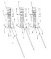
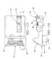
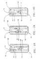
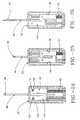
Figures 1-6 are side views of an embodiment of the handle assembly of the present invention showing insertion and securing of the needle set into the locking lid and housing according to the present invention;Figures 7-8 are top views of a needle set;Figure 9 is a top view of an embodiment of a slidable extension attached to a housing according to the present invention;Figure 10 is a side view of an embodiment of the handle assembly showing the housing, the slidable extension and- a locking lid according to the present invention;Figure 11 is a front view of an embodiment of the handle assembly showing the locking lid extended in an open position according to the present invention;Figures 9a, 10a, and 11a are similar toFigures 9, 10, and 11 respectively, except these figures depict a handle that is not a part of the claimed invention, which has preset the stylet to a single non-adjustable length stroke, and has a modified slide actuator and lid latch mechanism.Figure 12 is an exploded side view of an embodiment of the handle assembly according to the present invention;Figure 13 is a top view of an embodiment of the slidable extension of the handle assembly illustrating the numeric indicator and window according to the present invention;Figure 14 is a broken away view of an embodiment of the slidable extension of the handle assembly through lines 14 - 14 ofFigure 13 according to the present invention;Figure 15 is a top view of an embodiment of a housing assembly having a needle set showing a needle extended 13 mm according to the present invention;Figure 16 is a top view of an embodiment of the housing assembly having the needle set showing the needle extended 15 mm according to the present invention;Figure 17 is a top view of an embodiment of the housing assembly having the needle set showing the needle extended 21 mm according to the present invention;Figures 18-20 are top views showing an embodiment of the inner mechanisms of the slidable extension and the housing at various stages of taking a biopsy sample according to the present invention;Figures 21-23 are inside bottom views of an embodiment of the housing at various stages of taking a biopsy sample according to the present invention;Figures 24-26 are inside bottom views of an embodiment of the housing having a needle set at various stages of taking a biopsy sample according to the present invention; andFigures 27a to 27e, and 28a to 28h are side views of an embodiment of the handle assembly having a needle set illustrating insertion of the needle set and the sequence of stages in retrieving a tissue sample according to the present invention.- The present invention will now be described with reference to
Figures 1 through 28 which in general relate to a novel handle assembly which can be used in a semi-automated biopsy procedure to assist in the extraction of tissue in a precise manner using only one of a user's hands. It is understood that the principles of the present invention may be suitable for a variety of functions and incorporated into various biopsy devices. - Referring now to
FIGs. 1 through 8 , there is shown ahandle assembly 40 and a needle set 42. Thehandle assembly 40 has anopening 44 that allows for the insertion of the needle set 42 as will be explained hereinafter. The needle set 42 (which is not part of this invention) is an integral unit and consists of an innerpointed tip stylet 46 and an outerhollow cannula 48, as shown inFIGs. 7 and 8 . Thestylet 46 and thecannula 48 are capable of being urged forward separately into the biopsy area in a defined motion in relation to each other. Thestylet 46 includes anotch 50 which is ground at the distal end of the needle and is a repository for the tissue that is pierced by a forward motion of the needle. The secondary motion of thecannula 48 coaxially over thestylet 46 cuts and captures the tissue in thenotch 50 of the needle, thus allowing the tissue to be removed from the biopsy area and examined outside the patient. - With reference to
FIGs. 9 through 12 , thehandle assembly 40 will now be described. Thehandle assembly 40 includes ahousing 52, a lockinglid 54, and aslidable extension 56. Thehousing 52 is rectangular in shape and has a hollow inside. Attached to the top of thehousing 52 is the single hand operatedextension 56 and attached to the bottom of thehousing 52 is the lockinglid 54. Both shield the inner mechanisms of the handle assembly, as will be explained hereinafter. The preferred material for thehandle assembly 40 is a lightweight plastic although it is understood that the handle assembly may be formed with metals, polymers and other materials. Moreover, the handle assembly may be disposable and delivered sterilized prior to the biopsy procedure. - Inside the
housing 52 are twocylindrical rods 58, 60 (FIG. 22 ) which guide thestylet 46 andcannula 48 when a biopsy is performed and a tissue sample retrieved. Therod 58, which guides thecannula 48, includes aspring 62 and acannula coupling 64 for engaging the cannula in the housing. The cannula 48 (FIG. 7 ) includes anaperture 66 in itsbase 68 for connecting to a protrusion or pin 70 (FIG. 21 ) on thecannula coupling 64. Thecannula coupling 64 is pushed against thespring 62 by acannula pushing member 72, which is attached to the extension 56 (FIG. 1 ), until it reaches a position wherein thecannula 48 is spring loaded (i.e. in a spring compressed state) and ready for release. The-spring loaded position is obtained when a second locking member 110 (FIGs. 18-20 ) on thecannula coupling 64 engages afirst locking member 108 as explained hereinafter. Once thecannula 48 is released, thespring 62 urges thecannula 48 forward in a rapid motion severing the prolapsed tissue which resides in the needle notch. - Referring now to
FIGs. 10 through 12 , the lockinglid 54 is shown. The lockinglid 54 covers the bottom of thehousing 52 and has a descendingportion 74 havingside walls 76 which provides theopening 44 for insertion of the needle set. Theside walls 76 include acatch 78 on each side which engage a cut-out 80 (FIG. 1 ) located on each side of thehousing 52. Once the needle set is inserted, the descendingportion 74 is pushed up so that it is flush with the bottom of thehousing 52 and the needle set is secured inside the housing by engagement of thecatch 78 and cut-out 80 on each side of the housing. Thecatches 78 are wedge-shaped so as to allow thecatches 78 to be easily urged into the cut-outs 80. Once in place, the back edge of the wedge-shapedcatches 78 snaps into and locking hold the catches in the cut-outs. - Referring now to
FIGs. 13 through 17 , theslidable extension 56 is shown. Theslidable extension 56 covers the top of thehousing 52 and includes anadjustable wheel 82 on the rear end which allows a tissue sample of a predetermined size to be obtained during a biopsy procedure. Theslidable extension 56 is pushed rearward on the housing until thecannula 48 is locked in place in the spring loaded position. Theadjustable wheel 82 on the rear end of theslidable extension 56 is then turned to the desired penetration depth and a corresponding numeric indicator is shown through awindow 84 provided on the top of theslidable extension 56. The penetration depth may be set from 13 mm to 21 mm and is the distance that theneedle 46 is urged forward into the biopsy area, as shown inFIGs. 15-17 . It is to be understood that smaller and larger lengths can be possible with the same basic design as is understood by one skilled in the art. Theadjustable wheel 82 is attached to theslidable extension 56 by ascrew member 86. Located on thescrew member 86 is atrip bar 88. When theadjustable wheel 82 is turned, the desired preset penetration depth ofneedle 46 is obtained. Thetrip bar 88 includes a protrusion ortip 90 and moves forward along with theslidable extension 56. Thewheel 82 sets the position of the protrusion ortip 90 relative to theslidable extension 56. Theslidable extension 56, together with thetrip bar 88 are pushed forward, thus urging thestylet 46 forward the preset length, until the trip bar protrusion ortip 90 interacts with a first locking member protrusion 92 (FIG. 18 ) as explained hereinafter. - At the front of the
slidable extension 56, a pushing portion 94 (FIG. 9 ) is provided. The pushingportion 94 includes ribs 96 (FIG. 13 ) for enhanced friction between the user's thumb and the pushing portion during the biopsy procedure. The pushingportion 94 also provides an apparatus to single-handedly extend thestylet 46 manually into the biopsy area. Located on the bottom of theslidable extension 56 near the front is astylet needle coupling 98 for securing the stylet and the cannula pushing member 72 (FIGs. 21-23 ) for pushing thecannula coupling 64 against thespring 62. When the handle assembly is assembled, thestylet coupling 98 and thecannula pushing member 72 are located within thehousing 52. Thestylet coupling 98 includes a protrusion or pin 100 which is inserted into an aperture 102 (FIGs. 7, 8 ) located on abase 104 of thestylet 46. - Considering
FIGs. 18 through 20 , in detail, these figures depict top cross-section views of thehandle assembly 40 showing the operation of theslidable extension 56 and the related internal parts.FIG. 18 shows the mechanisms of the slidable extension which moves the stylet and the cannula. Thecannula pushing member 72 and thestylet coupling 98, which are attached to theslidable extension 56, are shown in a starting position. The trip bar protrusion ortip 90, the lockingmember protrusion 92 and thefirst locking member 108 are also depicted.FIGs. 19 ,22 ,25 , shows the stylet and the cannula being forced rearward by theslidable extension 56 and thecannula pushing member 72 on theextension 56 until thefirst locking member 108 engages thesecond locking member 110 on thecannula pushing member 72 and the cannula is cocked. Once the notch of thesecond locking member 110 has engaged the protrusion of thefirst locking member 108 so that the cannula is locked in a spring loaded position (FIG. 19 ), and the length of the tissue sample is adjusted if desired, theslidable extension 56, and thus the stylet, is urged forward into the biopsy area by manually pushing the pushingportion 94 forward.FIG. 20 shows thetrip bar protrusion 90 being moved forward by theextension 56 until the lockingmember protrusion 92 is deflected to the point of releasing thefirst locking member 108 from thesecond locking member 110 of thecannula coupling 64. The cannula of the needle set is then urged rapidly forward by the spring in order to sever and capture the tissue sample. - Considering
FIGs. 21-23 , in detail, these figures depict cross-section inside bottom views of the embodiment of thehandle assembly 40.FIG. 21 shows thestylet coupling 98 and thecannula coupling 64 in the starting position. The protrusions or pins 100, 70 ofstylet coupling 98 and thecannula coupling 64 are inserted into theapertures stylet 46 and of thecannula 48, and thereby position thestylet 46 andcannula 48 relative to thehousing 52 of thehandle 40. Theslidable extension 56 is connected to thestylet coupling 98 and thecannula pushing member 72. Therods housing 52 via thestylet coupling 98 and thecannula coupling 64, respectively. Thespring 62 is also provided for powering the cannula when it severs the tissue captured in the notch of the stylet.FIG. 22 shows thestylet coupling 98 and thecannula coupling 64 being moved rearward at the point where thefirst locking member 108 engages the second locking member 110 (FIG. 19 ). Theneedle coupling 98, thecannula coupling 64 and the spring are guided along the rods.FIG. 23 depicts the stage where the stylet has been inserted into the biopsy area the predetermined distance (as set bywheel 82 and when the pushingportion 94 of theslidable extension 56 has been manually pushed forward) and thecannula coupling 98 and the cannula are in the spring loaded position ready to be actuated. - Considering
FIGs. 24-26 , in detail, these figures depict bottom cross-section views of thehandle assembly 40 including the needle set 42 showing the operation of theslidable extension 56 and the related internal parts that detail the stages of the biopsy procedure.FIG. 24 shows the needle set 42 and thehandle assembly 40 in the starting position. Theapertures FIG. 25 shows theneedle 46 and thecannula 48 after the stylet and the cannula have been moved rearward and thefirst locking member 108 has engaged the second locking member 110 (FIG. 19 ).FIG. 26 shows the assembly wherein thestylet 46 has been urged forward to a predetermined distance and thecannula 48 remains in the spring loaded position ready for release. - As shown in
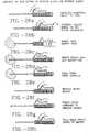
FIGs. 27a-e , the needle set 42 is inserted into thehandle assembly 40 in the descendingportion 74 of the lockinglid 54 which is then pushed upward and secured via thecatch 78 and the cut-outs 80 located on each side of the locking lid and the housing, respectively. In single-handed operation (FIGs. 28a-h ), theslidable extension 56 is moved rearward until thecannula 48 is in the spring loaded position and the first locking member has engaged the second locking member (FIG. 28b ). Theadjustable wheel 82 on the extension is turned to set the needle to a predetermined distance for insertion into the biopsy area (FIG. 28c ). Thestylet 46 and thecannula 48 are inserted into the patient near the biopsy area. Thestylet 46 is then urged into the biopsy area the predetermined distance by theslidable extension 56 so that the tissue is pierced and relaxes into thenotch 50 of the needle (FIG. 28d ). The slidable extension is pushed forward by the user's thumb. The cannula is then actuated when the trip bar protrusion deflects the locking member protrusion. The cannula rapidly slides forward so that the tissue in the notch is severed and retained in the notch of the stylet (FIG. 28e ). Thestylet 46 and thecannula 48 are both moved rearward by theextension 56, thereby disengaging the biopsy area (FIG. 28f ) and the needle set is removed from the patient. Thestylet 46 is then pressed forward using theslidable extension 56 so that the tissue sample is exposed and may be removed. Moving theslidable extension 56 rearward again reestablishes thestylet 46 and thecannula 48 in relation to each other in order to allow subsequent reinsertions into the biopsy area for additional tissue samples. Figs. 9a, 10a, and 11a depict an example of a handle not part of the claimed invention, where elements that are similar to the first embodiment ofhandle 40 are similarly numbered.Handle 41 includes an extension oractuator 57 which is slidable and operable with a single hand. Actuator has no adjusting wheel and thus handle 41 is present for a single stylet throw length and thus a single tissue sample length.Actuator 57 includes first and second upstanding protrusions which can be engaged by, for example, a thumb to push the actuator back and forth with respect to the handle in order to operate the handle and needle set as discussed above.Handle 41 includes forward facing, wedge-shaped, locking hooks 79 which engage slots 81 in order to locklid 74 in a closed configuration with respect tohousing 52. The wedge shape ofhooks 79 allows hooks to be slightly deflected as they pass slots 81 and then snaps into slots 81 when hooks 79 are aligned with slots 81.- Accordingly, the present invention provides for an inventive handle assembly and needle set which simplifies the biopsy procedure and which is easy to use and make. The disposable handle assembly thus affords a simpler design allowing the handle to be inexpensive to make and more compact.
- Although the invention has been described in detail herein, it should be understood that the invention is not limited to the embodiment herein disclosed but is defined by the appended claims.
Claims (4)
- A biopsy handle adapted to receiving a needle set assembly having a stylet (46) adapted for piercing and storing a tissue sample and a cannula adapted for severing and trapping the tissue sample, the biopsy handle comprising:a housing (52) adapted to accepting the needle set;an actuator (56) slidably attached to the housing (52) and adapted to selectively positioning the stylet (46) and the cannula (48) relative to the housing (52); andsaid actuator (56) includes an element (94) which is adapted to allow the actuator to be slid in a forward and a reverse direction with respect to the housing (52) in order to move the stylet (46) and the cannula (48) relative to the housing (52) using a single hand of a user,characterised in thatsaid actuator (56) includes a member (82) that is adapted to set the length of a sample of tissue that the stylet (46) can take.
- The biopsy handle of claim 1 wherein:said actuator has a base (104) that is slidably attached to said housing; andsaid element of said actuator includes a projection (100) from said slidable base of said actuator, which projection has first and second sides, which first and second sides are adapted to be urged by the single hand of the user, with urging on the first side for moving the actuator forwardly and urging on the second side for moving the actuator rearwardly.
- The biopsy handle of claim 1 wherein the element is a first protrusion (96) adapted to be engaged by a user's hand.
- The biopsy handle of claim 3 wherein said actuator includes a second protrusion that is adapted to be engaged by a user's hand.
Applications Claiming Priority (3)
| Application Number | Priority Date | Filing Date | Title |
|---|---|---|---|
| US76181 | 1998-05-12 | ||
| US09/076,181US6283925B1 (en) | 1998-05-12 | 1998-05-12 | Biopsy needle handle |
| PCT/US1999/010223WO1999058049A1 (en) | 1998-05-12 | 1999-05-11 | Biopsy needle handle |
Publications (3)
| Publication Number | Publication Date |
|---|---|
| EP1077633A1 EP1077633A1 (en) | 2001-02-28 |
| EP1077633A4 EP1077633A4 (en) | 2003-05-07 |
| EP1077633B1true EP1077633B1 (en) | 2009-04-08 |
Family
ID=22130444
Family Applications (1)
| Application Number | Title | Priority Date | Filing Date |
|---|---|---|---|
| EP99920424AExpired - LifetimeEP1077633B1 (en) | 1998-05-12 | 1999-05-11 | Biopsy needle handle |
Country Status (8)
| Country | Link |
|---|---|
| US (1) | US6283925B1 (en) |
| EP (1) | EP1077633B1 (en) |
| JP (1) | JP2002514451A (en) |
| AT (1) | ATE427694T1 (en) |
| CA (1) | CA2331450C (en) |
| DE (1) | DE69940690D1 (en) |
| DK (1) | DK1077633T3 (en) |
| WO (1) | WO1999058049A1 (en) |
Families Citing this family (91)
| Publication number | Priority date | Publication date | Assignee | Title |
|---|---|---|---|---|
| US8109885B2 (en) | 2002-03-19 | 2012-02-07 | C. R. Bard, Inc. | Biopsy device for removing tissue specimens using a vacuum |
| EP1524940B1 (en) | 2002-03-19 | 2011-08-24 | Bard Dublin ITC Limited | Biopsy device and biopsy needle module that can be inserted into the biopsy device |
| US8690791B2 (en) | 2002-05-31 | 2014-04-08 | Vidacare Corporation | Apparatus and method to access the bone marrow |
| US10973545B2 (en) | 2002-05-31 | 2021-04-13 | Teleflex Life Sciences Limited | Powered drivers, intraosseous devices and methods to access bone marrow |
| US11298202B2 (en) | 2002-05-31 | 2022-04-12 | Teleflex Life Sciences Limited | Biopsy devices and related methods |
| US8668698B2 (en) | 2002-05-31 | 2014-03-11 | Vidacare Corporation | Assembly for coupling powered driver with intraosseous device |
| US20070049945A1 (en) | 2002-05-31 | 2007-03-01 | Miller Larry J | Apparatus and methods to install, support and/or monitor performance of intraosseous devices |
| US7951089B2 (en) | 2002-05-31 | 2011-05-31 | Vidacare Corporation | Apparatus and methods to harvest bone and bone marrow |
| US8142365B2 (en) | 2002-05-31 | 2012-03-27 | Vidacare Corporation | Apparatus and method for accessing the bone marrow of the sternum |
| EP2039298B1 (en) | 2002-05-31 | 2017-10-25 | Vidacare LLC | Apparatus to access bone marrow |
| US7811260B2 (en) | 2002-05-31 | 2010-10-12 | Vidacare Corporation | Apparatus and method to inject fluids into bone marrow and other target sites |
| US8641715B2 (en) | 2002-05-31 | 2014-02-04 | Vidacare Corporation | Manual intraosseous device |
| US9072543B2 (en) | 2002-05-31 | 2015-07-07 | Vidacare LLC | Vascular access kits and methods |
| US10973532B2 (en) | 2002-05-31 | 2021-04-13 | Teleflex Life Sciences Limited | Powered drivers, intraosseous devices and methods to access bone marrow |
| US9451968B2 (en) | 2002-05-31 | 2016-09-27 | Vidacare LLC | Powered drivers, intraosseous devices and methods to access bone marrow |
| US7850620B2 (en) | 2002-05-31 | 2010-12-14 | Vidacare Corporation | Biopsy devices and related methods |
| US9314228B2 (en) | 2002-05-31 | 2016-04-19 | Vidacare LLC | Apparatus and method for accessing the bone marrow |
| US11337728B2 (en) | 2002-05-31 | 2022-05-24 | Teleflex Life Sciences Limited | Powered drivers, intraosseous devices and methods to access bone marrow |
| USD489456S1 (en) | 2002-10-22 | 2004-05-04 | Allegiance Corporation | Biopsy device handle assembly |
| US20040077973A1 (en)* | 2002-10-22 | 2004-04-22 | Groenke Gregory C. | Biopsy device handle assembly |
| DE20305093U1 (en)* | 2003-03-29 | 2003-09-11 | Heske, Norbert F., 82288 Kottgeisering | Coaxial cannula with sealing element |
| DE10314240B4 (en) | 2003-03-29 | 2025-05-28 | Bard Dublin Itc Ltd. | Pressure generation unit |
| US7625346B2 (en) | 2003-05-30 | 2009-12-01 | Boston Scientific Scimed, Inc. | Transbronchial needle aspiration device |
| US9504477B2 (en) | 2003-05-30 | 2016-11-29 | Vidacare LLC | Powered driver |
| CN101536926B (en) | 2004-01-26 | 2012-07-18 | 维达保健公司 | Manual interosseous device |
| US7815642B2 (en) | 2004-01-26 | 2010-10-19 | Vidacare Corporation | Impact-driven intraosseous needle |
| JP4814229B2 (en) | 2004-07-09 | 2011-11-16 | バード ペリフェラル ヴァスキュラー インコーポレイテッド | Transport device for biopsy device |
| ITBO20040532A1 (en)* | 2004-08-26 | 2004-11-26 | Aticarta S P A | RIGID WRAPPING FOR SMOKING ITEMS WITH HINGED COVER CONNECTED BY GLUING |
| US7850650B2 (en) | 2005-07-11 | 2010-12-14 | Covidien Ag | Needle safety shield with reset |
| US7905857B2 (en) | 2005-07-11 | 2011-03-15 | Covidien Ag | Needle assembly including obturator with safety reset |
| US7828773B2 (en) | 2005-07-11 | 2010-11-09 | Covidien Ag | Safety reset key and needle assembly |
| US8998848B2 (en) | 2004-11-12 | 2015-04-07 | Vidacare LLC | Intraosseous device and methods for accessing bone marrow in the sternum and other target areas |
| US7517321B2 (en) | 2005-01-31 | 2009-04-14 | C. R. Bard, Inc. | Quick cycle biopsy system |
| US20060200041A1 (en)* | 2005-03-04 | 2006-09-07 | Ethicon Endo-Surgery, Inc. | Biopsy device incorporating an adjustable probe sleeve |
| US7517322B2 (en)* | 2005-03-04 | 2009-04-14 | Ethicon Endo-Surgery, Inc. | Biopsy device with variable side aperture |
| US20060276747A1 (en) | 2005-06-06 | 2006-12-07 | Sherwood Services Ag | Needle assembly with removable depth stop |
| GB0513720D0 (en)* | 2005-07-05 | 2005-08-10 | Srivatsa Kadiyali M | Introducing device with wheel operator |
| US7731692B2 (en) | 2005-07-11 | 2010-06-08 | Covidien Ag | Device for shielding a sharp tip of a cannula and method of using the same |
| US20070016101A1 (en)* | 2005-07-13 | 2007-01-18 | Feldman Dennis D | Core Biopsy Device |
| JP4991723B2 (en) | 2005-08-10 | 2012-08-01 | シー・アール・バード・インコーポレーテッド | Single insertion multiple sampling biopsy device with integrated marker |
| EP1921998B8 (en) | 2005-08-10 | 2021-07-07 | C.R.Bard, Inc. | Single-insertion, multiple sampling biopsy device with linear drive |
| ES2539578T3 (en) | 2005-08-10 | 2015-07-02 | C.R. Bard, Inc. | Multi-sample biopsy device and single insert with various transport systems |
| US7654735B2 (en) | 2005-11-03 | 2010-02-02 | Covidien Ag | Electronic thermometer |
| US7766843B2 (en)* | 2006-03-03 | 2010-08-03 | Ethicon Endo-Surgery, Inc. | Biopsy method |
| WO2007110076A1 (en)* | 2006-03-24 | 2007-10-04 | B-K Medical Aps | Biopsy system |
| EP3417792B1 (en) | 2006-08-21 | 2022-03-02 | C. R. Bard, Inc. | Self-contained handheld biopsy needle |
| US8944069B2 (en) | 2006-09-12 | 2015-02-03 | Vidacare Corporation | Assemblies for coupling intraosseous (IO) devices to powered drivers |
| EP2073728B1 (en) | 2006-09-12 | 2018-11-07 | Teleflex Medical Devices S.à.r.l. | Biopsy device |
| EP2068743B1 (en) | 2006-09-12 | 2017-03-15 | Vidacare LLC | Medical procedures trays, kits and related methods |
| EP3189787B1 (en) | 2006-09-12 | 2019-01-09 | Teleflex Medical Devices S.à.r.l. | Medical procedures trays and related methods |
| SI2086418T1 (en) | 2006-10-06 | 2011-05-31 | Bard Peripheral Vascular Inc | Tissue handling system with reduced operator exposure |
| US8262586B2 (en) | 2006-10-24 | 2012-09-11 | C. R. Bard, Inc. | Large sample low aspect ratio biopsy needle |
| US8974410B2 (en) | 2006-10-30 | 2015-03-10 | Vidacare LLC | Apparatus and methods to communicate fluids and/or support intraosseous devices |
| US8357104B2 (en) | 2007-11-01 | 2013-01-22 | Coviden Lp | Active stylet safety shield |
| US8241225B2 (en) | 2007-12-20 | 2012-08-14 | C. R. Bard, Inc. | Biopsy device |
| US7854706B2 (en) | 2007-12-27 | 2010-12-21 | Devicor Medical Products, Inc. | Clutch and valving system for tetherless biopsy device |
| US8197419B2 (en) | 2008-05-30 | 2012-06-12 | Inrad, Inc. | Biopsy device having specimen length adjustment |
| US8192369B2 (en)* | 2008-05-30 | 2012-06-05 | Inrad, Inc. | Apparatus for cocking a biopsy device |
| US8167815B2 (en)* | 2008-12-18 | 2012-05-01 | Devicor Medical Products, Inc. | Biopsy device with retractable cutter |
| US7846109B2 (en)* | 2008-12-18 | 2010-12-07 | Devicor Medical Products, Inc. | Biopsy device with sliding cutter cover |
| US8366635B2 (en)* | 2008-12-18 | 2013-02-05 | Devicor Medical Products, Inc. | Biopsy probe and targeting set interface |
| US7862518B2 (en)* | 2008-12-18 | 2011-01-04 | Devicor Medical Products, Inc. | Biopsy device with telescoping cutter cover |
| US20100160822A1 (en)* | 2008-12-18 | 2010-06-24 | Parihar Shailendra K | Biopsy Device with Detachable Needle |
| WO2010107424A1 (en) | 2009-03-16 | 2010-09-23 | C.R. Bard, Inc. | Biopsy device having rotational cutting |
| AU2009344276B2 (en) | 2009-04-15 | 2014-06-05 | C.R. Bard, Inc. | Biopsy apparatus having integrated fluid management |
| US8206316B2 (en) | 2009-06-12 | 2012-06-26 | Devicor Medical Products, Inc. | Tetherless biopsy device with reusable portion |
| US9173641B2 (en) | 2009-08-12 | 2015-11-03 | C. R. Bard, Inc. | Biopsy apparatus having integrated thumbwheel mechanism for manual rotation of biopsy cannula |
| US8430824B2 (en) | 2009-10-29 | 2013-04-30 | Bard Peripheral Vascular, Inc. | Biopsy driver assembly having a control circuit for conserving battery power |
| US8485989B2 (en) | 2009-09-01 | 2013-07-16 | Bard Peripheral Vascular, Inc. | Biopsy apparatus having a tissue sample retrieval mechanism |
| US8597206B2 (en) | 2009-10-12 | 2013-12-03 | Bard Peripheral Vascular, Inc. | Biopsy probe assembly having a mechanism to prevent misalignment of components prior to installation |
| US8337416B2 (en)* | 2010-07-23 | 2012-12-25 | Cook Medical Technologies Llc | Biopsy device |
| KR101147564B1 (en)* | 2012-01-03 | 2012-05-21 | 권혁호 | Pen type device for ultrasound guided fine needle aspiration cytology and biopsy |
| US9474511B2 (en)* | 2012-10-08 | 2016-10-25 | Devicor Medical Products, Inc. | Tissue biopsy device with selectively rotatable linked thumbwheel and tissue sample holder |
| ES2924635T3 (en) | 2012-11-21 | 2022-10-10 | Bard Inc C R | Core needle biopsy device |
| USD735332S1 (en) | 2013-03-06 | 2015-07-28 | C. R. Bard, Inc. | Biopsy device |
| USD737440S1 (en) | 2013-03-07 | 2015-08-25 | C. R. Bard, Inc. | Biopsy device |
| US10092276B2 (en)* | 2013-03-15 | 2018-10-09 | Cook Medical Technologies Llc | Tissue acquisition device with indication system |
| CA2902221A1 (en) | 2013-03-20 | 2014-09-25 | Bard Peripheral Vascular, Inc. | Biopsy device |
| USD735333S1 (en) | 2013-06-26 | 2015-07-28 | C. R. Bard, Inc. | Biopsy device |
| ES2726985T3 (en) | 2013-11-05 | 2019-10-11 | Bard Inc C R | Biopsy device that has integrated vacuum |
| US9968373B1 (en)* | 2014-02-21 | 2018-05-15 | Surgentec, Llc | Handles for needle assemblies |
| WO2016178656A1 (en) | 2015-05-01 | 2016-11-10 | C. R. Bard, Inc. | Biopsy device |
| US10709429B2 (en) | 2016-12-05 | 2020-07-14 | Argon Medical Devices Inc. | Biopsy device handle |
| US11844500B2 (en) | 2017-05-19 | 2023-12-19 | Merit Medical Systems, Inc. | Semi-automatic biopsy needle device and methods of use |
| US11793498B2 (en) | 2017-05-19 | 2023-10-24 | Merit Medical Systems, Inc. | Biopsy needle devices and methods of use |
| US11116483B2 (en) | 2017-05-19 | 2021-09-14 | Merit Medical Systems, Inc. | Rotating biopsy needle |
| CN109674515B (en)* | 2017-10-18 | 2021-08-06 | 江苏风和医疗器材股份有限公司 | Accommodation space adjusting method |
| US12419620B2 (en) | 2019-08-22 | 2025-09-23 | Argon Medical Devices, Inc. | Core-severing cannula for biopsy devices |
| US12295556B2 (en) | 2019-09-27 | 2025-05-13 | Merit Medical Systems, Inc. | Rotation biopsy system and handle |
| US12150627B2 (en) | 2019-12-11 | 2024-11-26 | Merit Medical Systems, Inc. | Bone biopsy device and related methods |
| IT202200005303A1 (en)* | 2022-03-18 | 2023-09-18 | Francesca Musicco | BIOPSY GUN |
Family Cites Families (36)
| Publication number | Priority date | Publication date | Assignee | Title |
|---|---|---|---|---|
| DE141108C (en) | ||||
| DE10321C (en) | A. ROBINSON in Chicago (V. St. v. N. A.) | Apparatus for post-fermentation of leaf tobacco using moist heat | ||
| GB709714A (en) | 1950-11-17 | 1954-06-02 | Eric Oliver Longley | Improvements relating to hypodermic needles |
| GB748451A (en) | 1952-12-01 | 1956-05-02 | Eric Oliver Longley | Improvements relating to hypodermic needles |
| US3090384A (en) | 1960-04-15 | 1963-05-21 | Mfg Process Lab Inc | Needle |
| US3732858A (en) | 1968-09-16 | 1973-05-15 | Surgical Design Corp | Apparatus for removing blood clots, cataracts and other objects from the eye |
| US3844272A (en) | 1969-02-14 | 1974-10-29 | A Banko | Surgical instruments |
| US3788320A (en) | 1972-02-25 | 1974-01-29 | Kendall & Co | Spinal needle |
| US4210146A (en) | 1978-06-01 | 1980-07-01 | Anton Banko | Surgical instrument with flexible blade |
| US4266555A (en) | 1979-11-09 | 1981-05-12 | Khosrow Jamshidi | Biopsy needle with stylet and cannula orientation |
| US4403617A (en) | 1981-09-08 | 1983-09-13 | Waters Instruments, Inc. | Biopsy needle |
| US4469109A (en)* | 1981-12-24 | 1984-09-04 | Creative Research And Manufacturing Inc. | Bone marrow aspiration needle |
| WO1983003343A1 (en) | 1982-03-31 | 1983-10-13 | ALLARD, Jan, Hakan | A device for taking tissue samples |
| US4476864A (en) | 1982-09-29 | 1984-10-16 | Jirayr Tezel | Combined multiple punch and single punch hair transplant cutting device |
| DE3341117C2 (en) | 1983-11-12 | 1986-02-06 | Josef 7512 Rheinstetten Lindenberg | Biopsy cannula |
| US4655226A (en) | 1983-12-16 | 1987-04-07 | Southland Instruments, Inc. | Disposable biopsy needle unit |
| US4776346A (en) | 1984-02-10 | 1988-10-11 | Dan Beraha | Biopsy instrument |
| US4600014A (en) | 1984-02-10 | 1986-07-15 | Dan Beraha | Transrectal prostate biopsy device and method |
| US4570632A (en) | 1984-03-16 | 1986-02-18 | Woods Randall L | Cystotome for eye surgery and method of opening lens capsule |
| FR2577412B1 (en) | 1985-02-20 | 1989-04-07 | Biolog Ind Sarl | CORD PUNCTURE DEVICE |
| US4651752A (en) | 1985-03-08 | 1987-03-24 | Fuerst Erwin J | Biopsy needle |
| DE3518547C2 (en) | 1985-05-23 | 1994-04-14 | Angiomed Ag | Hollow needle of a biopsy set |
| SE456886B (en) | 1986-02-19 | 1988-11-14 | Radiplast Ab | DEVICE FOR TAPE SAMPLING WITH A NATIONAL DISPENSER |
| US4838282A (en)* | 1987-02-26 | 1989-06-13 | Manan Manufacturing Co., Inc. | Bone biopsy needle assembly |
| US4733671A (en) | 1987-03-17 | 1988-03-29 | Mehl Donald N | Tissue needle |
| US5064411A (en) | 1988-11-04 | 1991-11-12 | Gordon Iii Kilbourn | Protective medical device |
| US4924878A (en) | 1988-11-07 | 1990-05-15 | Nottke James E | Actuating mechanism for biopsy needle |
| US5025797A (en) | 1989-03-29 | 1991-06-25 | Baran Gregory W | Automated biopsy instrument |
| US4958625A (en) | 1989-07-18 | 1990-09-25 | Boston Scientific Corporation | Biopsy needle instrument |
| USRE34056E (en) | 1989-07-31 | 1992-09-08 | C.R. Bard, Inc. | Tissue sampling device |
| US5316013A (en) | 1991-08-26 | 1994-05-31 | Hart Enterprises, Inc. | Oriented biopsy needle assembly |
| WO1993022971A1 (en)* | 1992-05-11 | 1993-11-25 | Boston Scientific Corporation | Multiple needle biopsy instrument |
| US5220926A (en) | 1992-07-13 | 1993-06-22 | Jones George T | Finger mounted core biopsy guide |
| US5779647A (en)* | 1995-06-07 | 1998-07-14 | Chau; Sonny | Automated biopsy instruments |
| IT1285548B1 (en)* | 1996-01-26 | 1998-06-18 | Alberto Bauer | SURGICAL APPARATUS FOR BIOPSY |
| US5752923A (en)* | 1996-06-24 | 1998-05-19 | Medical Device Technologies, Inc. | Biopsy instrument with handle and needle set |
- 1998
- 1998-05-12USUS09/076,181patent/US6283925B1/ennot_activeExpired - Lifetime
- 1999
- 1999-05-11DKDK99920424Tpatent/DK1077633T3/enactive
- 1999-05-11EPEP99920424Apatent/EP1077633B1/ennot_activeExpired - Lifetime
- 1999-05-11CACA002331450Apatent/CA2331450C/ennot_activeExpired - Fee Related
- 1999-05-11DEDE69940690Tpatent/DE69940690D1/ennot_activeExpired - Lifetime
- 1999-05-11WOPCT/US1999/010223patent/WO1999058049A1/enactiveApplication Filing
- 1999-05-11ATAT99920424Tpatent/ATE427694T1/ennot_activeIP Right Cessation
- 1999-05-11JPJP2000547904Apatent/JP2002514451A/enactivePending
Also Published As
| Publication number | Publication date |
|---|---|
| DK1077633T3 (en) | 2009-08-10 |
| CA2331450C (en) | 2009-02-17 |
| CA2331450A1 (en) | 1999-11-18 |
| EP1077633A4 (en) | 2003-05-07 |
| JP2002514451A (en) | 2002-05-21 |
| ATE427694T1 (en) | 2009-04-15 |
| WO1999058049A1 (en) | 1999-11-18 |
| DE69940690D1 (en) | 2009-05-20 |
| US6283925B1 (en) | 2001-09-04 |
| EP1077633A1 (en) | 2001-02-28 |
Similar Documents
| Publication | Publication Date | Title |
|---|---|---|
| EP1077633B1 (en) | Biopsy needle handle | |
| US6083176A (en) | Automated biopsy needle handle | |
| CA2331444C (en) | Reusable automated biopsy needle handle | |
| US5752923A (en) | Biopsy instrument with handle and needle set | |
| US8048003B2 (en) | Vacuum assisted biopsy device | |
| US7226424B2 (en) | Methods and devices for automated biopsy and collection of soft tissue | |
| US7766843B2 (en) | Biopsy method | |
| US5188118A (en) | Automatic biopsy instrument with independently actuated stylet and cannula | |
| EP0556243B1 (en) | Automatic biopsy instrument | |
| US7988642B2 (en) | Vacuum assisted biopsy device | |
| US20070208272A1 (en) | Biopsy device | |
| EP2131745A1 (en) | Vacuum assisted biopsy device | |
| AU2008221322B2 (en) | Vacuum assisted biopsy device | |
| WO1993004629A1 (en) | Biopsy instrument with radius ground cutting edge |
Legal Events
| Date | Code | Title | Description |
|---|---|---|---|
| PUAI | Public reference made under article 153(3) epc to a published international application that has entered the european phase | Free format text:ORIGINAL CODE: 0009012 | |
| 17P | Request for examination filed | Effective date:20001130 | |
| AK | Designated contracting states | Kind code of ref document:A1 Designated state(s):AT BE CH CY DE DK ES FI FR GB GR IE IT LI LU MC NL PT SE | |
| RIN1 | Information on inventor provided before grant (corrected) | Inventor name:TERWILLIGER, RICHARD, A. | |
| RIC1 | Information provided on ipc code assigned before grant | Free format text:7A 61B 5/00 A, 7A 61B 10/00 B | |
| A4 | Supplementary search report drawn up and despatched | Effective date:20030321 | |
| GRAP | Despatch of communication of intention to grant a patent | Free format text:ORIGINAL CODE: EPIDOSNIGR1 | |
| GRAS | Grant fee paid | Free format text:ORIGINAL CODE: EPIDOSNIGR3 | |
| GRAA | (expected) grant | Free format text:ORIGINAL CODE: 0009210 | |
| AK | Designated contracting states | Kind code of ref document:B1 Designated state(s):AT BE CH CY DE DK ES FI FR GB GR IE IT LI LU MC NL PT SE | |
| REG | Reference to a national code | Ref country code:GB Ref legal event code:FG4D | |
| REG | Reference to a national code | Ref country code:CH Ref legal event code:EP | |
| REG | Reference to a national code | Ref country code:IE Ref legal event code:FG4D | |
| REF | Corresponds to: | Ref document number:69940690 Country of ref document:DE Date of ref document:20090520 Kind code of ref document:P | |
| REG | Reference to a national code | Ref country code:CH Ref legal event code:NV Representative=s name:ING. MARCO ZARDI C/O M. ZARDI & CO. S.A. | |
| REG | Reference to a national code | Ref country code:DK Ref legal event code:T3 | |
| REG | Reference to a national code | Ref country code:SE Ref legal event code:TRGR | |
| PG25 | Lapsed in a contracting state [announced via postgrant information from national office to epo] | Ref country code:PT Free format text:LAPSE BECAUSE OF FAILURE TO SUBMIT A TRANSLATION OF THE DESCRIPTION OR TO PAY THE FEE WITHIN THE PRESCRIBED TIME-LIMIT Effective date:20090908 Ref country code:ES Free format text:LAPSE BECAUSE OF FAILURE TO SUBMIT A TRANSLATION OF THE DESCRIPTION OR TO PAY THE FEE WITHIN THE PRESCRIBED TIME-LIMIT Effective date:20090719 Ref country code:AT Free format text:LAPSE BECAUSE OF FAILURE TO SUBMIT A TRANSLATION OF THE DESCRIPTION OR TO PAY THE FEE WITHIN THE PRESCRIBED TIME-LIMIT Effective date:20090408 | |
| PG25 | Lapsed in a contracting state [announced via postgrant information from national office to epo] | Ref country code:MC Free format text:LAPSE BECAUSE OF NON-PAYMENT OF DUE FEES Effective date:20090531 | |
| PLBE | No opposition filed within time limit | Free format text:ORIGINAL CODE: 0009261 | |
| STAA | Information on the status of an ep patent application or granted ep patent | Free format text:STATUS: NO OPPOSITION FILED WITHIN TIME LIMIT | |
| 26N | No opposition filed | Effective date:20100111 | |
| PG25 | Lapsed in a contracting state [announced via postgrant information from national office to epo] | Ref country code:GR Free format text:LAPSE BECAUSE OF FAILURE TO SUBMIT A TRANSLATION OF THE DESCRIPTION OR TO PAY THE FEE WITHIN THE PRESCRIBED TIME-LIMIT Effective date:20090709 | |
| PG25 | Lapsed in a contracting state [announced via postgrant information from national office to epo] | Ref country code:LU Free format text:LAPSE BECAUSE OF NON-PAYMENT OF DUE FEES Effective date:20090511 | |
| PG25 | Lapsed in a contracting state [announced via postgrant information from national office to epo] | Ref country code:CY Free format text:LAPSE BECAUSE OF FAILURE TO SUBMIT A TRANSLATION OF THE DESCRIPTION OR TO PAY THE FEE WITHIN THE PRESCRIBED TIME-LIMIT Effective date:20090408 | |
| REG | Reference to a national code | Ref country code:FR Ref legal event code:PLFP Year of fee payment:18 | |
| PGFP | Annual fee paid to national office [announced via postgrant information from national office to epo] | Ref country code:NL Payment date:20160526 Year of fee payment:18 | |
| PGFP | Annual fee paid to national office [announced via postgrant information from national office to epo] | Ref country code:IE Payment date:20160527 Year of fee payment:18 Ref country code:FI Payment date:20160527 Year of fee payment:18 Ref country code:GB Payment date:20160527 Year of fee payment:18 Ref country code:DE Payment date:20160527 Year of fee payment:18 Ref country code:CH Payment date:20160527 Year of fee payment:18 | |
| PGFP | Annual fee paid to national office [announced via postgrant information from national office to epo] | Ref country code:SE Payment date:20160527 Year of fee payment:18 Ref country code:FR Payment date:20160530 Year of fee payment:18 Ref country code:BE Payment date:20160527 Year of fee payment:18 Ref country code:DK Payment date:20160525 Year of fee payment:18 Ref country code:IT Payment date:20160520 Year of fee payment:18 | |
| REG | Reference to a national code | Ref country code:DE Ref legal event code:R119 Ref document number:69940690 Country of ref document:DE | |
| REG | Reference to a national code | Ref country code:CH Ref legal event code:PL | |
| REG | Reference to a national code | Ref country code:SE Ref legal event code:EUG Ref country code:DK Ref legal event code:EBP Effective date:20170531 | |
| REG | Reference to a national code | Ref country code:NL Ref legal event code:MM Effective date:20170601 | |
| GBPC | Gb: european patent ceased through non-payment of renewal fee | Effective date:20170511 | |
| PG25 | Lapsed in a contracting state [announced via postgrant information from national office to epo] | Ref country code:FI Free format text:LAPSE BECAUSE OF NON-PAYMENT OF DUE FEES Effective date:20170511 | |
| REG | Reference to a national code | Ref country code:IE Ref legal event code:MM4A | |
| PG25 | Lapsed in a contracting state [announced via postgrant information from national office to epo] | Ref country code:SE Free format text:LAPSE BECAUSE OF NON-PAYMENT OF DUE FEES Effective date:20170512 Ref country code:LI Free format text:LAPSE BECAUSE OF NON-PAYMENT OF DUE FEES Effective date:20170531 Ref country code:CH Free format text:LAPSE BECAUSE OF NON-PAYMENT OF DUE FEES Effective date:20170531 | |
| REG | Reference to a national code | Ref country code:FR Ref legal event code:ST Effective date:20180131 | |
| PG25 | Lapsed in a contracting state [announced via postgrant information from national office to epo] | Ref country code:NL Free format text:LAPSE BECAUSE OF NON-PAYMENT OF DUE FEES Effective date:20170601 | |
| REG | Reference to a national code | Ref country code:BE Ref legal event code:MM Effective date:20170531 | |
| PG25 | Lapsed in a contracting state [announced via postgrant information from national office to epo] | Ref country code:IE Free format text:LAPSE BECAUSE OF NON-PAYMENT OF DUE FEES Effective date:20170511 Ref country code:GB Free format text:LAPSE BECAUSE OF NON-PAYMENT OF DUE FEES Effective date:20170511 Ref country code:DK Free format text:LAPSE BECAUSE OF NON-PAYMENT OF DUE FEES Effective date:20170531 Ref country code:DE Free format text:LAPSE BECAUSE OF NON-PAYMENT OF DUE FEES Effective date:20171201 | |
| PG25 | Lapsed in a contracting state [announced via postgrant information from national office to epo] | Ref country code:IT Free format text:LAPSE BECAUSE OF NON-PAYMENT OF DUE FEES Effective date:20170511 Ref country code:FR Free format text:LAPSE BECAUSE OF NON-PAYMENT OF DUE FEES Effective date:20170531 | |
| PG25 | Lapsed in a contracting state [announced via postgrant information from national office to epo] | Ref country code:BE Free format text:LAPSE BECAUSE OF NON-PAYMENT OF DUE FEES Effective date:20170531 |