EP1077371A1 - Procedure, device and fitting for monitoring a pipeline system - Google Patents
Procedure, device and fitting for monitoring a pipeline systemDownload PDFInfo
- Publication number
- EP1077371A1 EP1077371A1EP99116006AEP99116006AEP1077371A1EP 1077371 A1EP1077371 A1EP 1077371A1EP 99116006 AEP99116006 AEP 99116006AEP 99116006 AEP99116006 AEP 99116006AEP 1077371 A1EP1077371 A1EP 1077371A1
- Authority
- EP
- European Patent Office
- Prior art keywords
- arrangement
- messages
- fitting
- hydrant
- leak
- Prior art date
- Legal status (The legal status is an assumption and is not a legal conclusion. Google has not performed a legal analysis and makes no representation as to the accuracy of the status listed.)
- Granted
Links
- 238000012544monitoring processMethods0.000titleclaimsabstractdescription21
- 238000000034methodMethods0.000titleclaimsabstractdescription16
- 238000001514detection methodMethods0.000claimsabstractdescription18
- 230000005236sound signalEffects0.000claimsabstractdescription5
- XLYOFNOQVPJJNP-UHFFFAOYSA-NwaterSubstancesOXLYOFNOQVPJJNP-UHFFFAOYSA-N0.000claimsdescription40
- 239000007788liquidSubstances0.000claimsdescription23
- 230000005540biological transmissionEffects0.000claimsdescription10
- 238000009434installationMethods0.000claimsdescription6
- 230000007257malfunctionEffects0.000claimsdescription5
- 239000000126substanceSubstances0.000claimsdescription5
- 230000003287optical effectEffects0.000claimsdescription3
- 238000011156evaluationMethods0.000description11
- 239000003651drinking waterSubstances0.000description9
- 235000020188drinking waterNutrition0.000description9
- 230000008901benefitEffects0.000description7
- 230000007246mechanismEffects0.000description7
- 230000006378damageEffects0.000description5
- 230000007547defectEffects0.000description5
- 238000005259measurementMethods0.000description5
- 230000000007visual effectEffects0.000description3
- 238000005422blastingMethods0.000description2
- 230000008859changeEffects0.000description2
- 238000012937correctionMethods0.000description2
- 238000013461designMethods0.000description2
- 238000005457optimizationMethods0.000description2
- 238000002604ultrasonographyMethods0.000description2
- 230000002457bidirectional effectEffects0.000description1
- 238000004891communicationMethods0.000description1
- 230000008878couplingEffects0.000description1
- 238000010168coupling processMethods0.000description1
- 238000005859coupling reactionMethods0.000description1
- 230000001419dependent effectEffects0.000description1
- 239000011521glassSubstances0.000description1
- 238000007689inspectionMethods0.000description1
- 238000012423maintenanceMethods0.000description1
- 238000004519manufacturing processMethods0.000description1
- 238000012806monitoring deviceMethods0.000description1
- 230000000149penetrating effectEffects0.000description1
- 230000008569processEffects0.000description1
- 230000004044responseEffects0.000description1
- 238000010079rubber tappingMethods0.000description1
- 238000003860storageMethods0.000description1
- 230000009625temporal interactionEffects0.000description1
Images

Classifications
- G—PHYSICS
- G01—MEASURING; TESTING
- G01M—TESTING STATIC OR DYNAMIC BALANCE OF MACHINES OR STRUCTURES; TESTING OF STRUCTURES OR APPARATUS, NOT OTHERWISE PROVIDED FOR
- G01M3/00—Investigating fluid-tightness of structures
- G01M3/02—Investigating fluid-tightness of structures by using fluid or vacuum
- G01M3/04—Investigating fluid-tightness of structures by using fluid or vacuum by detecting the presence of fluid at the leakage point
- G01M3/24—Investigating fluid-tightness of structures by using fluid or vacuum by detecting the presence of fluid at the leakage point using infrasonic, sonic, or ultrasonic vibrations
- G01M3/243—Investigating fluid-tightness of structures by using fluid or vacuum by detecting the presence of fluid at the leakage point using infrasonic, sonic, or ultrasonic vibrations for pipes
- G—PHYSICS
- G01—MEASURING; TESTING
- G01M—TESTING STATIC OR DYNAMIC BALANCE OF MACHINES OR STRUCTURES; TESTING OF STRUCTURES OR APPARATUS, NOT OTHERWISE PROVIDED FOR
- G01M3/00—Investigating fluid-tightness of structures
- G01M3/02—Investigating fluid-tightness of structures by using fluid or vacuum
- G01M3/26—Investigating fluid-tightness of structures by using fluid or vacuum by measuring rate of loss or gain of fluid, e.g. by pressure-responsive devices, by flow detectors
- G01M3/28—Investigating fluid-tightness of structures by using fluid or vacuum by measuring rate of loss or gain of fluid, e.g. by pressure-responsive devices, by flow detectors for pipes, cables or tubes; for pipe joints or seals; for valves ; for welds
- G01M3/2807—Investigating fluid-tightness of structures by using fluid or vacuum by measuring rate of loss or gain of fluid, e.g. by pressure-responsive devices, by flow detectors for pipes, cables or tubes; for pipe joints or seals; for valves ; for welds for pipes
- G01M3/2815—Investigating fluid-tightness of structures by using fluid or vacuum by measuring rate of loss or gain of fluid, e.g. by pressure-responsive devices, by flow detectors for pipes, cables or tubes; for pipe joints or seals; for valves ; for welds for pipes using pressure measurements
Definitions
- the present inventionrelates to a Process, an arrangement, a valve and a system for monitoring piping systems for liquids, especially for water, according to the generic terms of independent claims.
- Monitoring devices for piping systemsare generally used where a early detection of a leak or malfunction is not possible or difficult with the naked eye. This problem arises especially with piping systems and system components which are heavy or are not accessible at all.
- Drinking water supply networksrepresent such an area of application where an early Visual detection of leaks in the underground piping system is practically not possible.
- the presence a leakoften shows up very late and often in the form of property damage caused by this. To however, these damages are visible often in advance and over a longer period of time large losses of drinking water arose.
- By Defects on the fittings themselves due to faulty ones Operation as well as by unauthorized removal of Drinking watercan also cause damage and economic Losses come to it as well prevent applies.
- DE-A 197 57 581describes a fitting for Connection to an underground pipe system, which Measured values for leak detection using structure-borne noise measurement detected.
- the measured valuesare saved periodically and optically via a sight glass on the fitting or optoelectrically or via an electronic coupling read or read.
- a major disadvantage of this The deviceis that the reading or reading of the measured values decentralized and with not insignificant human resources takes place.
- an evaluationmust then be carried out of the measurement data to determine whether a There is leakage or not. This means that early detection is only possible if that Reading or reading and the subsequent evaluation in very short intervals and that this work must also be done if there is no leak. Monitoring the Fittings themselves regarding defects on the same and their operating states are also not possible here.
- At least one fitting or pipeline of a piping systeman arrangement attached, which can directly detect leaks in the system and / or valve fill levels can detect and leak detection and / or when a value is exceeded or undershot Valve fill level as a finished result of leak alarm messages and / or fill level messages.
- For Leakage monitoringhas the advantage of that a regular reevaluation from the previous on the Device read out measurement data by people Leak detection becomes superfluous. It only becomes relevant and transmitted already evaluated information, i.e. there is only a leak alarm message if a leak has been detected. It also offers the possibility of filling levels within a fitting monitor and report as soon as a certain level is exceeded or fallen below.
- fittings arranged above ground underground water supply networkssuch as Hydrants can fill the tap unnoticed with water due to defects or incorrect operation in winter Destruction of the valve by frost blasting. On Another advantage is that this also works an unauthorized water withdrawal can be determined.
- an arrangement for monitoring a pipeline network built into a hydrantand there in particular in the area of the hydrant valve rod and / or in Main hydrant valve area. This results in a simple and inexpensive way to cover the whole area Leakage monitoring of drinking water supply networks without structural interventions on its piping system.
- this arrangementis also provided Above or below ground in other fittings, pipe sockets, Pipe bends, pipe tapping and the like of piping systems incorporate the water or other May contain liquids.
- the arrangementpreferably has at least one liquid sound transducer, in particular a hydrophone, which is advantageously used in the Main hydrant valve integrated or attached to it is.
- a structure-borne sound transducerin particular an accelerometer
- the use of liquid sound pickupsoffers the advantage that the ratio Useful signal for interference signal of the leak noise to be measured is significantly larger than with a structure-borne noise measurement using an accelerometer.
- a use of structure-borne noise sensorsis advantageous in that the sound pickup does not have to be in contact with the liquid, which facilitates the constructive design can contribute. It is because of the different Advantages also conceivable arrangements both liquid and structure-borne noise sensors exhibit.
- Level sensorsused, in particular Float switches, but they are also all other types of sensors that detect a liquid level allow, e.g. also capacitive sensors and Resistance sensors, conceivable.
- the submission of messagescan be visual and / or acoustically, for example in the form of light signals or sounds.
- the delivery of Messagesare sent by remote transmission and in particular, if it is done by wireless transmission.
- the remote transmissioncome optical, acoustic and electrical cables such as light guides, piping systems (e.g. the monitored piping system) or electrical cables in question, for wireless transmission all known methods such as radio, ultrasound, Infrared etc. is advantageous for remote transmission, that this eliminates the regular on-site inspection, which when monitoring the piping system with multiple arrangements can be very expensive.
- Using the wireless transmission results as Another advantageis that in the case mentioned above complex infrastructure of communication lines can be dispensed with and therefore also mobile message recipient (e.g. in a vehicle) possible are.
- the arrangementis programmable and / or parameterizable. This has the advantage that the Evaluation algorithms and the control functions individually can be adapted to the respective application can, reducing the likelihood of leak detection can be increased.
- the messages from received a control centerwhich is designed in this way may be the messages of several Accept orders essentially at the same time can.
- This centercan perceive the messages make and / or to a recipient, in particular to forward a pager or a wireless phone.
- a pager or a wireless phoneLikewise come in place of mobile phones and pagers other receivers and transmitters / receivers in question, which also with wires or lines with the Central can be connected.
- competent authoritye.g. the responsible service staff, automatically inform you as soon as one certain message from an order from the respective Area of responsibility arrives or instructions from Accept recipients.
- the Hydrant 1 at its lower end, which connects to the drinking water supply network 2is connected, a main valve 3 on, the valve body on the inside of the hydrant facing side to the hydrant main valve rod 4 is adjacent, in which the arrangement 5 for Monitoring of the piping system 2 is located.
- the embodiment 5is battery-operated, however, designs are also conceivable which have a fixed power connection or own Energy generation means such as solar cells combined with accumulators.
- the valve bodyOn the Drinking water supply network 2 side facing the main valve 3, the valve body carries a hydrophone 6, which belongs to arrangement 5 and the waterborne sound within the Pipe system 2 takes.
- the hydrophone 6is on the Pipe system 2 facing side of the shut-off devices, whereby the hydrophone 6 regardless of the position of the Shut-off devices with the water of the piping system 2 in Connection is established and can absorb the water sound.
- a float switch 7arranged, which also belongs to the arrangement 5 and for the detection of exceeding or falling below a certain level inside the hydrant serves. Conceivable here are all the other types of sensors, too allow detection of a water level, e.g. also capacitive sensors and resistance sensors. Now kick a leak 8 in the piping system 2, so this creates due to an outflow of water under pressure Sound waves that pass through the pipeline as Structure-borne noise and through the water in the piping system 2 spread out as water sound.
- the main hydrant valve 3becomes light If it is open or if it is slightly leaky, water will leak in the hydrant interior 10, which, however, over the drainage mechanism 11 below the float switch 7 flows off. The flow through the opening gap or the leak creates sound waves, which is picked up by the hydrophone 6 and by the Arrangement 5 evaluated, recognized as leak 8 and as such will be reported.
- the main hydrant valve 3is completely opened, the drainage mechanism 11 closed and the hydrant 1 fills up completely Water. As soon as a certain level is reached, the float switch 7 reports that it has been exceeded the same.
- the arrangement 5now gives a fill level notification which they use in this version like the leak alarm message via antenna 9 by radio sends a recipient.
- the drainage mechanism 11is partial or completely blocked, this can possibly be the case with one leaking or not fully closed main hydrant valve 3 penetrating into the hydrant inner region 10 Do not drain water immediately or only slowly and leads to a filling of the hydrant interior 10 with water, which also leads to the submission of a fill level notification leads through the arrangement 5.
- the arrangement 5also has the Possibility of internal faults such as too low Battery voltage or missing measurement signals and submit corresponding reports.
- the evaluation algorithmsare adaptable to the application and control functions of the arrangement 5 programmable and / or parameterizable. This can take place for the first time in the manufacturing plant or on site at the first installation. It is also envisaged that after installation, an adjustment and correction of the Evaluation algorithms and control functions at any time is possible.
- the same interfacesare suitable for this, via which the reports are also submitted provided that they are designed bidirectionally.
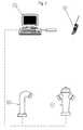
- Fig. 2is a system for monitoring of a piping system for water, which is made up of two hydrants 1a, 1b, which with inventive Arrangements are provided, from a center 13 and out a cell phone 14 exists.
- hydrantsall other fittings can be used, which are provided with an arrangement according to the invention are and also specifically for monitoring on the piping system attached tubular body and the like.
- Commercial mobile phonesalso replace mobile phones Pager or other receivers and transmitters / receivers in question, which also via wires or Lines can be connected to the center 13.
- the sent from the arrangements of the hydrants 1a, 1b Messagesare received by the control center 13 and made perceivable by this, for example by certain messages on an overview board about the Piping system by lighting up lamps are displayed, an alarm siren sounds or on Flashing alarm light comes on. Also the messages from the control center to the mobile phone 14 of the person responsible Service personnel forwarded. Even if here only a center 13 and a mobile phone 14 is shown, it is also conceivable that several Centers 13 are linked and that a center 13 from a variety of service phones 14 depending depending on the type and origin of the report certain, responsible for the respective case Cellphone 14 forwards. Particularly useful this appears with very large water supply networks, where different people or positions for Hydrants 1a, 1b are responsible in certain regions.
- the Head office 13can be unmanned and these selection decisions based on suitable algorithms.
- the connection between control center 13 and cellphone 14unidirectional, but it is the same conceivable that there is a bidirectional connection which e.g. the acknowledgment of an alarm message or e.g. remote parameterization and / or remote programming of a Arrangement in a hydrant la, 1b or a fitting allows the response to the headquarters 13. Is too it provided that a parameterization and / or Programming of the arrangements from the control center 13 can be done.
- the control center 13is aware of the message history of the individual arrangements with suitable Algorithms an automatic, individual optimization the evaluation algorithms and control functions individual orders or that the Central 13 simultaneous changes to multiple arrangements makes.
Landscapes
- Physics & Mathematics (AREA)
- General Physics & Mathematics (AREA)
- Examining Or Testing Airtightness (AREA)
- Pipeline Systems (AREA)
Abstract
Description
Translated fromGermanDie vorliegende Erfindung betrifft einVerfahren, eine Anordnung, eine Armatur und eine Anlagezur Überwachung von Rohrleitungsystemen für Flüssigkeiten,insbesondere für Wasser, gemäss den Oberbegriffender unabhängigen Ansprüche.The present invention relates to aProcess, an arrangement, a valve and a systemfor monitoring piping systems for liquids,especially for water, according to the generic termsof independent claims.
Überwachungseinrichtungen für Rohrleitungssystemekommen im allgemeinen dort zum Einsatz, wo einefrühzeitige Erkennung einer Leckage oder einer Störungmit dem blossen Auge nicht möglich bzw. schwierig ist.Dieses Problem ergibt sich speziell bei Rohrleitungssystemenund -systembestandteilen, welche schwer oderüberhaupt nicht zugänglich sind.Monitoring devices for piping systemsare generally used where aearly detection of a leak or malfunctionis not possible or difficult with the naked eye.This problem arises especially with piping systemsand system components which are heavy orare not accessible at all.
Ein solches Anwendungsgebiet stellen Trinkwasserversorgungsnetzedar, bei denen eine frühzeitigevisuelle Erkennung von Leckagen am erdverlegten Rohrleitungssystempraktisch nicht möglich ist. Das Vorhandenseineiner Leckage zeigt sich oft erst sehr spät undoft in Form von durch diese verursachte Sachschäden. Bisdiese Schäden jedoch sichtbar zu Tage treten, sindoftmals bereits vorgängig und über einen längeren Zeitraumgrosse Verluste an Trinkwasser entstanden. DurchDefekte an den Armaturen selbst, durch fehlerhafteBedienung sowie durch nicht autorisierte Entnahme vonTrinkwasser kann es zusätzlich zu Schäden und wirtschaftlichenEinbussen kommen, die es ebenso zuverhindern gilt. Es ist grundsätzlich bekannt, Lecksaufgrund von charakteristischen Geräuschen zu erkennen,welche durch die an der Leckstelle austretende Flüssigkeiterzeugt werden, wofür z.B. auf DE-A-195 28 287 undden dort genannten Stand der Technik verwiesen werdenkann.Drinking water supply networks represent such an area of applicationwhere an earlyVisual detection of leaks in the underground piping systemis practically not possible. The presencea leak often shows up very late andoften in the form of property damage caused by this. Tohowever, these damages are visibleoften in advance and over a longer period of timelarge losses of drinking water arose. ByDefects on the fittings themselves due to faulty onesOperation as well as by unauthorized removal ofDrinking water can also cause damage and economicLosses come to it as wellprevent applies. It is generally known to have leaksrecognizable on the basis of characteristic noises,caused by the liquid emerging at the leakgenerated for which e.g. on DE-A-195 28 287 andthe prior art mentioned therecan.
DE-A 197 57 581 beschreibt eine Armatur zumAnschluss an ein erdverlegtes Leitungssystem, welche mittels Körperschallmessung Messwerte zur Leckerkennungerfasst. Die Messwerte werden periodisch gespeichert undüber ein an der Armatur befindliches Schauglas optischbzw. optoelektrisch oder über eine elektronische Kopplungab- bzw. ausgelesen. Ein wesentlicher Nachteil dieserVorrichtung ist es, dass das Ab- bzw. Auslesen der Messwertedezentral und unter nicht unerheblichem Personaleinsatzstattfindet. Zudem muss sodann erst eine Auswertungder Messdaten erfolgen, um festzustellen ob eineLeckage vorhanden ist oder nicht. Dieses bedeutet, dasseine frühzeitige Erkennung nur dann gegeben ist, wenn dasAb- bzw. Auslesen und das anschliessende Auswerten insehr kurzen Zeitabständen durchgeführt wird, und dassdieser Arbeitseinsatz auch dann geleistet werden muss,wenn kein Leck vorhanden ist. Eine Überwachung derArmaturen selbst bezüglich Defekten an denselben undderen Betriebszuständen ist hier zudem nicht möglich.DE-A 197 57 581 describes a fitting forConnection to an underground pipe system, whichMeasured values for leak detection using structure-borne noise measurementdetected. The measured values are saved periodically andoptically via a sight glass on the fittingor optoelectrically or via an electronic couplingread or read. A major disadvantage of thisThe device is that the reading or reading of the measured valuesdecentralized and with not insignificant human resourcestakes place. In addition, an evaluation must then be carried outof the measurement data to determine whether aThere is leakage or not. This means thatearly detection is only possible if thatReading or reading and the subsequent evaluation invery short intervals and thatthis work must also be doneif there is no leak. Monitoring theFittings themselves regarding defects on the same andtheir operating states are also not possible here.
Es stellt sich daher die Aufgabe, einVerfahren und eine Vorrichtung zur Verfügung zu stellen,welche eine Erkennung und Meldung von Leckagen inRohrleitungssystemen für Flüssigkeiten, insbesondere fürWasser, und/oder von Defekten und Betriebszuständen anderen Armaturen ermöglichen, die die genannten Nachteilenicht aufweisen.The task therefore arisesTo provide methods and an apparatuswhich is a detection and reporting of leaks inPiping systems for liquids, in particular forWater, and / or defects and operating conditionswhose fittings allow the disadvantages mentioneddo not have.
Diese Aufgabe wird von dem Verfahren, derAnordnung, der Armatur und der Anlage gemäss den unabhängigenAnsprüchen gelöst.This task is performed by the procedure thatArrangement, the valve and the system according to the independentClaims solved.
Demgemäss ist an mindestens einer Armaturoder Rohrleitung eines Rohrleitungssystems eine Anordnungangebaut, welche direkt Lecks im System erkennen kannund/oder Armaturenfüllstände erkennen kann und bei Leckerkennungund/oder bei Über- bzw. Unterschreiten einesArmaturenfüllstandes als fertiges Resultat Leckalarmmeldungenund/oder Füllstandszustandsmeldungen abgibt. Fürdie Lecküberwachung ergibt sich hierdurch der Vorteil,dass eine regelmässige Nachauswertung von zuvor an derVorrichtung ausgelesenen Messdaten durch Personen zur Leckerkennung überflüssig wird. Es werden nur relevanteund bereits fertig ausgewertete Informationen übermittelt,d.h. es erfolgt nur eine Leckalarmmeldung, wennein Leck erkannt worden ist. Darüber hinaus bietet sichdie Möglichkeit, Füllstände innerhalb einer Armatur zuüberwachen und eine Meldung zu übermitteln, sobald einbestimmter Füllstand über- oder unterschritten wird.Speziell bei oberirdisch angeordneten Armaturen anerdverlegten Wasserversorgungsnetzen wie z.B. Hydrantenkann ein unbemerktes sich Füllen der Armatur mit Wasserdurch Defekte oder Fehlbedienung im Winter zu einerZerstörung der Armatur durch Frostsprengung führen. Einweiterer Vorteil besteht darin, dass sich hierdurch aucheine nicht autorisierte Wasserentnahme festellen lässt.Accordingly, there is at least one fittingor pipeline of a piping system an arrangementattached, which can directly detect leaks in the systemand / or valve fill levels can detect and leak detectionand / or when a value is exceeded or undershotValve fill level as a finished result of leak alarm messagesand / or fill level messages. ForLeakage monitoring has the advantage ofthat a regular reevaluation from the previous on theDevice read out measurement data by peopleLeak detection becomes superfluous. It only becomes relevantand transmitted already evaluated information,i.e. there is only a leak alarm message ifa leak has been detected. It also offersthe possibility of filling levels within a fittingmonitor and report as soon as acertain level is exceeded or fallen below.Especially for fittings arranged above groundunderground water supply networks such as Hydrantscan fill the tap unnoticed with waterdue to defects or incorrect operation in winterDestruction of the valve by frost blasting. OnAnother advantage is that this also worksan unauthorized water withdrawal can be determined.
Es ist des weiteren vorteilhaft, dassBetriebsstörungen automatisch erkannt werden und dass beideren Erkennung Störungsmeldungen in Abhängigkeit von denerkannten Betriebsstörungen abgegeben werden. Auf dieseWeise kann sofort erkannt werden, wo eine Leck- undFüllstandsüberwachung nicht in Betrieb ist oder wennWartungsarbeiten, z.B. ein Batteriewechsel, erforderlichwerden.It is also advantageous thatMalfunctions are automatically recognized and that attheir detection fault messages depending on therecognized malfunctions are given. To thisWay can be immediately recognized where a leak andLevel monitoring is not in operation or ifMaintenance work, e.g. a battery change, requiredbecome.
Auch ist es bevorzugt, dass physikalischeund/oder chemische Kenngrössen der Flüssigkeit in derRohrleitung, im Leitungssystem im Bereich der Armaturund/oder innerhalb der Armatur ermittelt werden undZustandsmeldungen in Abhängigkeit von den Kenngrössenabgegeben werden. Auf diese Weise lassen sich beispielsweisedie Flüssigkeitstemperatur, der Flüssigkeitsdruckund die Durchflussmenge lokal und auf einfache Weiseüberwachen.It is also preferred that physicaland / or chemical parameters of the liquid in thePipeline, in the piping system in the area of the valveand / or determined within the fitting andStatus messages depending on the parametersbe delivered. In this way, for examplethe liquid temperature, the liquid pressureand the flow rate locally and easilymonitor.
Aus einer Kombination der verschiedenenMeldungen einer Anordnung können zudem Informationen überden Betriebszustand der diese Anordnung beinhaltendenArmatur abgeleitet werden. So lassen sich z.B. bei einemHydranten aus Leck- und Füllstandszustandsmeldungen, undeventuell noch zusätzlich kombiniert mit Wasserdruckmeldungen, Zustände wie Wasserentnahme, gefüllter Hydrantohne Wasserentnahme bei fehlerhafter Ausserbetriebnahme(Hauptventil geöffnet, Seitenventile geschlossen) oderein mangelhafter oder verstopfter Entwässerungsmechanismusmit dichtem oder auch undichtem Hauptventil unterscheiden.Diese Zustände können auch durch die Anordnungselbst als fertig ausgewertete Störungsmeldungenabgegeben werden und können, wie alle anderen Meldungenauch, bei Bedarf zusätzlich Zeitinformationen enthalten,welche hier Rückschlüsse auf Beginn und Ende einerWasserentnahme, auf den Zeitpunkt einer Fehlbedienungsowie auf den Grad der Verstopfung des Entwässerungsmechanismuszulassen.From a combination of the differentOrders of an order can also provide information aboutthe operating state of the device containing this arrangementFitting are derived. For example, at aHydrants from leakage and fill level reports, andpossibly additionally combined with water pressure messages,Conditions such as water withdrawal, filled hydrantwithout taking water in the event of faulty decommissioning(Main valve open, side valves closed) oran inadequate or blocked drainage mechanismdifferentiate with a tight or leaky main valve.These states can also be determined by the arrangementeven as fault reports evaluatedand can be submitted like all other reportsalso, if necessary, contain additional time information,which here conclusions about the beginning and end of aWater withdrawal, at the time of incorrect operationas well as the degree of clogging of the drainage mechanismallow.
In einer Ausführungsvariante der Erfindungist eine Anordnung zur Überwachung eines Rohrleitungsnetzesin einen Hydranten eingebaut, und dort insbesondereim Bereich der Hydranten-Ventilstange und/oder imBereich des Hydrantenhauptventils. Hierdurch ergibt sicheine einfache und kostengünstige Möglichkeit zur flächendeckendenLecküberwachung von Trinkwasserversorgungsnetzenohne bauliche Eingriffe an dessen Rohrleitungssystem.Es ist aber ebenso vorgesehen, diese Anordnungüber- oder unterirdisch in andere Armaturen, Rohrstutzen,Rohrbögen, Rohranbohrungen und dergleichen von Rohrleitungssystemeneinzubauen, die Wasser oder andereFlüssigkeiten beinhalten können.In an embodiment variant of the inventionis an arrangement for monitoring a pipeline networkbuilt into a hydrant, and there in particularin the area of the hydrant valve rod and / or inMain hydrant valve area. This results ina simple and inexpensive way to cover the whole areaLeakage monitoring of drinking water supply networkswithout structural interventions on its piping system.However, this arrangement is also providedAbove or below ground in other fittings, pipe sockets,Pipe bends, pipe tapping and the like of piping systemsincorporate the water or otherMay contain liquids.
Bevorzugterweise weist die Anordnungmindestens einen Flüssigkeitsschallaufnehmer, insbesondereein Hydrophon, auf, welcher mit Vorteil in dasHydrantenhauptventil integriert oder an dieses angebautist.The arrangement preferably hasat least one liquid sound transducer, in particulara hydrophone, which is advantageously used in theMain hydrant valve integrated or attached to itis.
In einer anderen bevorzugten Ausführung weistdie Anordnung einen Körperschallaufnehmer, insbesondereein Accelerometer, auf. Die Verwendung von Flüssigkeitsschallaufnehmernbietet den Vorteil, dass das VerhältnisNutzsignal zu Störsignal des zu messenden Leckgeräuschessignifikant grösser ist als bei einer Körperschallmessung mittels Accelerometer. Eine Verwendung von Körperschallaufnehmernist insofern vorteilhaft, als der Schallaufnehmernicht in Kontakt mit der Flüssigkeit stehen muss,was zu einer Erleichterung bei der konstruktiven Ausgestaltungbeitragen kann. Es sind aufgrund der unterschiedlichenVorteile auch Anordnungen denkbar, welchesowohl Flüssigkeits- als auch Körperschallaufnehmeraufweisen.In another preferred embodiment pointsthe arrangement a structure-borne sound transducer, in particularan accelerometer, on. The use of liquid sound pickupsoffers the advantage that the ratioUseful signal for interference signal of the leak noise to be measuredis significantly larger than with a structure-borne noise measurementusing an accelerometer. A use of structure-borne noise sensorsis advantageous in that the sound pickupdoes not have to be in contact with the liquid,which facilitates the constructive designcan contribute. It is because of the differentAdvantages also conceivable arrangementsboth liquid and structure-borne noise sensorsexhibit.
Zur Erkennung von Füllständen werden bevorzugterweiseFüllstandssensoren verwendet, inbesondereSchwimmerschalter, es sind aber auch alle anderen Artenvon Sensoren, welche eine Erkennung eines Flüssigkeitsstandeszulassen, so z.B. auch kapazitive Sensoren undWiderstandssensoren, denkbar.For the detection of fill levels are preferredLevel sensors used, in particularFloat switches, but they are also all other typesof sensors that detect a liquid levelallow, e.g. also capacitive sensors andResistance sensors, conceivable.
Die Abgabe von Meldungen kann optischund/oder akustisch, zum Beispiel in Form von Lichtsignalenoder Tönen, erfolgen.The submission of messages can be visualand / or acoustically, for example in the form of light signalsor sounds.
Auch ist es bevorzugt, wenn die Abgabe vonMeldungen durch Fernübermittlung erfolgt und insbesondere,wenn sie durch drahtlose Übermittlung erfolgt.Für die Fernübermittlung kommen optische, akustische undelektrische Leitungen wie zum Beispiel Lichtleiter, Rohrleitungssysteme(z.B. das überwachte Rohrleitungssystem)oder elektrische Kabel in Frage, für die drahtlose Übermittlungalle bekannten Methoden wie Funk, Ultraschall,Infrarot usw. Vorteilhaft bei der Fernübermittlung ist,dass hierdurch die regelmässige vor Ort Kontrolle entfällt,welche bei Überwachung des Rohrleitungssystems mitmehreren Anordnungen sehr aufwendig sein kann. Bei Verwendungder drahtlosen Übermittlung ergibt sich alsweiterer Vorteil, dass in oben erwähntem Fall auf eineaufwendige Infrastruktur von Kommunikationsleitungenverzichtet werden kann und dass somit ausserdem auchbewegliche Meldungsempfänger (z.B. in einem Fahrzeug)möglich sind.It is also preferred if the delivery ofMessages are sent by remote transmission and in particular,if it is done by wireless transmission.For the remote transmission come optical, acoustic andelectrical cables such as light guides, piping systems(e.g. the monitored piping system)or electrical cables in question, for wireless transmissionall known methods such as radio, ultrasound,Infrared etc. is advantageous for remote transmission,that this eliminates the regular on-site inspection,which when monitoring the piping system withmultiple arrangements can be very expensive. Usingthe wireless transmission results asAnother advantage is that in the case mentioned abovecomplex infrastructure of communication linescan be dispensed with and therefore alsomobile message recipient (e.g. in a vehicle)possible are.
In einer weiteren bevorzugten Ausführungsvarianteist die Anordnung programmierbar und/oder parametrierbar. Hieraus ergibt sich der Vorteil, dass dieAuswertealgorithmen und die Steuerungsfunktionen individuellauf den jeweiligen Anwendungsfall angepasst werdenkönnen, wodurch die Leckerkennungswahrscheinlichkeitgesteigert werden kann.In a further preferred embodiment variantthe arrangement is programmable and / orparameterizable. This has the advantage that theEvaluation algorithms and the control functions individuallycan be adapted to the respective applicationcan, reducing the likelihood of leak detectioncan be increased.
Bevorzugterweise kann die Parametrierung bzw.Programmierung ferngesteuert von einem von der Anordnungbzw. Armatur entfernt gelegenen Ort aus erfolgen und insbesonderedrahtlos von einem solchen Ort aus. Eine vorOrt Präsenz von Personal ist somit nur für die Erstinstallationund nachher ausschliesslich für Servicearbeitennach einer vorgängig erfolgten Störungsmeldungerforderlich. Auch eröffnet sich die Möglichkeit, eineautomatische Optimierung der Algorithmen und Funktioneneiner Anordnung in Abhängigkeit von deren Meldungshistorievorzunehmen.The parameterization orProgramming remotely from one of the arrangementor valve away from place and in particularwirelessly from such a place. One beforeThe presence of staff is therefore only for the initial installationand afterwards exclusively for service workafter a previous failure reportrequired. There is also the possibility of oneautomatic optimization of algorithms and functionsan arrangement depending on its message historyto make.
Bevorzugterweise werden die Meldungen voneiner Zentrale entgegengenommen, welche derart ausgestaltetsein kann, dass sie die Meldungen mehrererAnordnungen im wesentlichen zeitgleich entgegennehmenkann. Diese Zentrale kann die Meldungen wahrnehmbarmachen und/oder diese an einen Empfänger, insbesondere aneinen Pager oder ein drahtloses Telephon weiterleiten.Ebenso kommen an Stelle von Mobiltelephonen und Pagernauch andere Empfänger und Sender/Empfänger in Frage,welche zudem auch über Drähte oder Leitungen mit derZentrale verbunden sein können. Hierdurch ergibt sich derVorteil, dass eine zentrale Überwachung der Meldungenaller Anordnungen eines Rohrleitungsnetzes möglich ist,was eine erhöhte Kontroll- und Überwachungssicherheitgewährleistet. Auch besteht die Möglichkeit, diezuständige Stelle, z.B. das verantwortliche Servicepersonal,automatisch zu informieren, sobald einebestimmte Meldung von einer Anordnung aus dem jeweiligenZuständigkeitsbereich eintrifft bzw. Instruktionen vomEmpfänger entgegenzunehmen.The messages fromreceived a control center, which is designed in this waymay be the messages of severalAccept orders essentially at the same timecan. This center can perceive the messagesmake and / or to a recipient, in particular toforward a pager or a wireless phone.Likewise come in place of mobile phones and pagersother receivers and transmitters / receivers in question,which also with wires or lines with theCentral can be connected. This results in theAdvantage that central monitoring of the messagesall arrangements of a pipeline network are possible,what an increased control and surveillance securityguaranteed. There is also the possibility ofcompetent authority, e.g. the responsible service staff,automatically inform you as soon as onecertain message from an order from the respectiveArea of responsibility arrives or instructions fromAccept recipients.
Wenn die Programmierung und/oder Parametrierungder Anordnungen über die Zentrale erfolgt undinsbesondere wenn diese drahtlos erfolgt, ergibt sichzusätzlich die Möglichkeit, simultan an mehreren AnordnungenAnpassungen oder Korrekturen der Auswertealgorithmenund/oder Steuerungsfunktionen vorzunehmen.If programming and / or parameterizationthe orders are made via the head office andin particular if this is done wirelesslyadditionally the possibility to work simultaneously on several arrangementsAdjustments or corrections to the evaluation algorithmsand / or control functions.
Weitere bevorzugte Ausführungen der Erfindungergeben sich aus den abhängigen Ansprüchen sowie aus dernun folgenden Beschreibung anhand der Figuren. Dabeizeigen:
Der Grundaufbau einer bevorzugten Ausführungder Erfindung in Form einer Anordnung welche in einen anein Trinkwasserversorgungsnetz angebauten Hydranten eingebautist, zeigt Fig. 1. Wie zu ersehen ist, weist derHydrant 1 an seinem unteren Ende, welches an das Trinkwasserversorgungsnetz2 angeschlossen ist, ein Hauptventil3 auf, dessen Ventilkörper auf der dem Hydranteninnernzugewandten Seite an die Hydranten-Hauptventilstange4 angrenzt, in welcher sich die Anordnung 5 zurÜberwachung des Rohrleitungssystems 2 befindet. In diesemAusführungsbeispiel ist die Anordnung 5 batteriebetrieben,jedoch sind ebenso Ausführungen denkbar, welcheeinen festen Stromanschluss aufweisen oder eigeneEnergieerzeugungsmittel wie beispielsweise Solarzellenkombiniert mit Akkumulatoren aufweisen. Auf der demTrinkwasserversorgungsnetz 2 zugewandten Seite des Hauptventils3 trägt der Ventilkörper ein Hydrophon 6, welcheszur Anordnung 5 gehört und den Wasserschall innerhalb desRohrleitungssystems 2 aufnimmt. Bei Hydranten oderArmaturen, welche zwischen dem Hauptventil und demRohrleitungsnetz 2 noch zusätzliche Absperrogane besitzen, befindet sich das Hydrophon 6 auf der demRohrleitungssystem 2 zugewandten Seite der Absperrorgane,wodurch das Hydrophon 6 unabhängig von der Stellung derAbsperrorgane mit dem Wasser des Rohrleitungssystems 2 inVerbindung steht und den Wasserschall aufnehmen kann.The basic structure of a preferred embodimentthe invention in the form of an arrangement which in onea drinking water supply network built-in hydrants installed1 shows. As can be seen, theHydrant 1 at its lower end, which connects to the drinking
Ebenso denkbar sind Ausführungen, welchemittels Körperschallaufnehmern wie beispielsweiseAccelerometern den Körperschall des Rohrleitungssystems 2an der Armatur bzw. an der Rohrleitung selbst aufnehmen.Im Innenbereich des Hydranten 1 ist ein Schwimmerschalter7 angeordnet, welcher ebenfalls zur Anordnung 5 gehörtund zur Erkennung des Über- bzw. Unterschreitens einesbestimmten Füllstandes im Hydranteninnern dient. Denkbarsind hier auch alle anderen Arten von Sensoren, welcheeine Erkennung eines Wasserstandes zulassen, so z.B. auchkapazitive Sensoren und Widerstandssensoren. Tritt nunein Leck 8 im Rohrleitungssystem 2 auf, so erzeugt diesesinfolge eines Ausströmens von Wasser unter ÜberdruckSchallwellen, welche sich durch die Rohrleitung alsKörperschall und durch das Wasser im Rohrleitungssystem 2als Wasserschall ausbreiten. Bei dieser Ausführungsvariantewird der Wasserschall innerhalb des Rohrleitungssystems2 vom Hydrophon 6 aufgenommen und innerhalbder Anordnung 5 ausgewertet. Die Auswertung erfolgtdabei durch Analyse der Schallsignale, wodurch leckcharakteristischeSignale von den übrigen Schallereignissenunterschieden werden können. Die Auswertungerfolgt in der Anordnung vorzugsweise durch einen mitSpeichermitteln versehenen Rechner, der die digitalisiertenSchallsignale analysiert und über das Vorhandenseineines Lecks 8 entscheidet. Ergibt die Auswertung,dass eine Leckage 8 vorliegt, so gibt die Anordnung 5eine Leckalarmmeldung ab. Hierzu umfasst die dargestellteAnordnung 5 eine Antenne 9, welche oben auf dem Hydranten1 angebracht ist und mit welcher sie die Meldung an einenEmpfänger (nicht dargestellt) sendet. Neben der Abgabevon Meldungen über Funk sind verschiedene andere Ausführungen denkbar, so z.B. mittels elektrischen oderoptischen Leitungen oder z.B. mittels Ultraschall durchdie Luft oder durch die Rohrleitungswandungen bzw. durchdas sich im Rohrleitungsnetz befindliche Wasser. Auch istes denkbar, eine einfache optische Anzeige wie z.B. eineLampe oder Leuchtdiode aussen am Hydranten anzubringenoder ein hörbares akustisches Alarmsignal vom Hydrantenauszusenden.Versions which are also conceivableusing structure-borne noise sensors such asAccelerometers the structure-borne noise of the
Wird das Hydrantenhauptventil 3 leichtgeöffnet oder ist dieses leicht undicht, so tritt Wasserin den Hydranteninnenbereich 10 ein, welches jedoch überden Entwässerungsmechanismus 11 unterhalb des Schwimmerschalters7 abfliesst. Das Durchströmen des Öffnungsspaltesbzw. der Undichtigkeit erzeugt indes Schallwellen,welche vom Hydrophon 6 aufgenommen und von derAnordnung 5 ausgewertet, als Leck 8 erkannt und alssolches gemeldet werden.The
Wird das Hydrantenhauptventil 3 ganzgeöffnet, so wird der Entwässerungsmechanismus 11verschlossen und der Hydrant 1 füllt sich vollständig mitWasser. Sobald ein bestimmter Füllstand erreicht ist,meldet der Schwimmerschalter 7 das Überschreitendesselben. Die Anordnung 5 gibt nun eine Füllstandsüberschreitungsmeldungab, welche sie bei dieser Ausführungwie die Leckalarmmeldung über die Antenne 9 per Funk aneinen Empfänger sendet.The
Wird das Hydrantenhauptventil 3 anschliessendgeschlossen, so entweicht das sich im Hydranteninnenbereich10 befindliche Wasser über den Entwässerungsmechanismus11 und bei Unterschreiten eines bestimmtenFüllstandes meldet der Schwimmerschalter 7 dieses und dieAnordnung 5 gibt auf die vorher beschriebene Art undWeise eine Füllstandsunterschreitungsmeldung ab. Ebensoist es denkbar, dass eine Meldung erfolgt solange einFüllstand überschritten ist. Bei der hier dargestelltenAusführung mit Funkübermittlung und Batteriespeisung istes aus Gründen der beschränkten Lebensdauer der Batterien erstrebenswert, dass nur dann Meldungen versendet werden,wenn Zustandsänderungen auftreten und dass der jeweiligeletzte Zustand beim Empfänger gespeichert wird, bis eineanders lautende Meldung von der Anordnung 5 eintrifft. Essind aber ebenso Ausführungen denkbar, bei denen alleZustandsmeldungen praktisch "On-Line" abgegeben werden,unabhängig davon, ob eine Änderung eingetreten ist odernicht. Auch ist es denkbar, die Meldungen in festenIntervallen oder auf Anfrage hin abzugeben.Then the
Ist der Entwässerungsmechanismus 11 teilweiseoder ganz verstopft, so kann das eventuell bei einemundichten oder nicht vollständig geschlossenen Hydrantenhauptventil3 in den Hydranteninnenbereich 10 eindringendeWasser nicht sofort oder nur langsam abfliessenund führt zu einem Auffüllen des Hydranteninnenbereichs10 mit Wasser, was ebenfalls zur Abgabe einer Füllstandsüberschreitungsmeldungdurch die Anordnung 5 führt.The
Ist der Entwässerungsmechanismus 11 ganz verstopft,so kann nach einer Wasserentnahme das sich imHydranteninneraum 10 befindliche Wasser nicht abfliessen,wodurch die Füllstandsunterschreitungsmeldung nach abgeschlossenerWasserentnahme ausbleibt.If the
Werden nach einer Wasserentnahme an einemHydranten 1 mit Seitenventilen 12 fälschlicherweise dieSeitenventile 12 geschlossen und das Hauptventil 3 ingeöffnetem Zustand belassen, so ist der Hydranteninneraum10 ebenfalls mit Wasser gefüllt.Are after taking water from aFire hydrants 1 with
In allen beschriebenen Fällen, in denenWasser im Hydranteninnenraum 10 verbleibt, besteht in denWintermonaten die Gefahr einer Zerstörung des Hydrantendurch Frostsprengung.In all cases described, in whichWater remains in the
Neben den unabhängigen Leck- und Füllstandszustandsmeldungenlassen sich aus der Kombination derselbensowie aus deren zeitlichem Zusammenspiel zusätzlicheRückschlüsse auf verschiedene Betriebszuständeeines Hydranten ziehen, wie z.B. "Hydrant in Benutzungoder mit starker innerer Leckage", "gefüllter Hydrant ohne Wasserentnahme " sowie "vorschriftsgemässer Hydrantim Ruhezustand". Ergänzt man die Anordnung 5 um zusätzlicheSensoren zur Erfassung physikalischer und/oderchemischer Kenngrössen des Wassers, beispielsweise umeinen Sensor zur Aufnahme des Wasserdruckes vor demHydrantenhauptventil 3 und um einen Sensor zur Aufnahmedes Druckes im Hydranteninnenraum 10, so lassen sich nochweitaus differenziertere Betriebszustände bzw. Defekteableiten. Mit Hilfe geeigneten Auswertealgorithmen ist esauch denkbar, dass diese als zusätzliche Zustands-und/oder Störungsmeldungen fertig ausgewertet von derAnordnung 5 abgegeben werden und dass ausserdemphysikalische und/oder chemische Kenngrössen überwachtund gemeldet werden können.In addition to the independent leak and level status reportscan be combined from the sameas well as additional from their temporal interactionConclusions about different operating statesa hydrant, e.g. "Hydrant in useor with severe internal leakage "," filled hydrantwithout water withdrawal "and" proper hydrantat rest ". If
Auch verfügt die Anordnung 5 über dieMöglichkeit, interne Störungen wie z.B. zu niedrigeBatteriespannung oder fehlende Messsignale, zu erkennenund entsprechende Meldungen abzugeben.The
Um möglichst individuell auf den jeweiligenAnwendungsfall anpassbar zu sein, sind die Auswertealgorithmenund Steuerfunktionen der Anordnung 5programmierbar und/oder parametrierbar. Dieses kannerstmals im Herstellungswerk erfolgen oder vor Ort beider Erstinstallation. Auch ist es vorgesehen, dass nacherfolgter Installation eine Anpassung und Korrektur derAuswertealgorithmen und Steuerfunktionen jederzeitmöglich ist. Hierzu eignen sich die gleichen Schnittstellen,über welche auch die Meldungen abgegeben werden,vorausgesetzt dass diese bidirektional ausgestaltet sind.To be as individual as possible on the respectiveThe evaluation algorithms are adaptable to the applicationand control functions of the
In Fig. 2 ist eine Anlage zur Überwachungeines Rohrleitungssystems für Wasser dargestellt, die auszwei Hydranten 1a, 1b, welche mit erfindungsgemässenAnordnungen versehen sind, aus einer Zentrale 13 und auseinem Mobiltelephon 14 besteht. An Stelle von Hydrantenkönnen auch alle anderen Armaturen verwendet werden,welche mit einer erfindungsgemässen Anordnung versehensind und auch speziell für die Überwachung am Rohrleitungssystem angebrachte Rohrkörper und dergleichen.Ebenso kommen an Stelle von Mobiltelephonen handelsüblichePager oder auch andere Empfänger und Sender/-Empfängerin Frage, welche zudem auch über Drähte oderLeitungen mit der Zentrale 13 verbunden sein können. Dievon den Anordnungen der Hydranten 1a, 1b gesendetenMeldungen werden von der Zentrale 13 entgegengenommen undvon dieser wahrnehmbar gemacht, indem beispielsweisebestimmte Meldungen auf einer Übersichtstafel über dasRohrleitungssystem durch das Aufleuchten von Lampenangezeigt werden, eine Alarmsirene ertönt oder einAlarmblinklicht aufleuchtet. Auch werden die Meldungenvon der Zentrale an das Mobiltelephon 14 des verantwortlichenServicepersonals weitergeleitet. Auch wennhier nur eine Zentrale 13 und ein Mobiltelephon 14dargestellt ist, so ist es ebenso denkbar, dass mehrereZentralen 13 verknüpft sind und dass eine Zentrale 13 auseiner Vielzahl von Servicetelephonen 14 in Abhängigkeitvon der Art und Herkunft der Meldung diese nur an einbestimmtes, für den jeweiligen Fall zuständigesMobiltelephon 14 weiterleitet. Besonders sinnvollerscheint dieses bei sehr grossen Wasserversorgungsnetzen,bei denen verschiedene Personen oder Stellen fürHydranten 1a, 1b in bestimmten Regionen zuständig sind.Zudem kann es sinnvoll sein, wenn nur sehr wichtigeMeldungen von der Zentrale 13 weitergegeben werden. DieZentrale 13 kann unbemannt sein und diese Auswahlentscheideaufgrund geeigneter Algorithmen treffen. Indiesem Beispiel ist die Verbindung zwischen Zentrale 13und Mobiltelephon 14 unidirektional, es ist aber ebensodenkbar, das eine bidirektionale Verbindung bestehtwelche z.B. die Quittierung einer Alarmmeldung oder z.B.eine Fernparametrierung und/oder Fernprogrammierung einerAnordnung in einem Hydranten la, 1b oder einer Armaturüber die Rückantwort an die Zentrale 13 zulässt. Auch istes vorgesehen, dass eine Parametrierung und/oderProgrammierung der Anordnungen von der Zentrale 13 aus erfolgen kann. Denkbar ist hier ausserdem die Möglichkeit,dass die Zentrale 13 in Kenntnis der Meldungshistorieder einzelnen Anordnungen mit geeignetenAlgorithmen eine automatische, individuelle Optimierungder Auswertealgorithmen und Steuerungsfunktioneneinzelner Anordnungen vornimmt oder auch, dass dieZentrale 13 simultan Änderungen an mehreren Anordnungenvornimmt.In Fig. 2 is a system for monitoringof a piping system for water, which is made up oftwo
Die vorgängige Beschreibung beschreibt dieErfindung am Beispiel eines Verfahrens, einer Anordnung,einer Armatur und einer Anlage zur Überwachung von Rohrleitungssystemenfür Wasser. Die Anwendung bei Rohrleitungssystemenfür Wasser ist bevorzugt, jedoch ist dieErfindung nicht auf diese beschränkt sondern kann auchbei Rohrleitungssystemen für andere flüssige Medieneingesetzt werden.The previous description describes theInvention using the example of a method, an arrangement,a valve and a system for monitoring piping systemsfor water. The application in piping systemsis preferred for water, howeverInvention is not limited to this but can alsofor piping systems for other liquid mediabe used.
Claims (26)
Translated fromGermanPriority Applications (4)
| Application Number | Priority Date | Filing Date | Title |
|---|---|---|---|
| EP99116006AEP1077371B1 (en) | 1999-08-14 | 1999-08-14 | Procedure, device and fitting for monitoring a pipeline system |
| AT99116006TATE256282T1 (en) | 1999-08-14 | 1999-08-14 | METHOD, ARRANGEMENT AND FITTING FOR MONITORING A PIPING SYSTEM |
| ES99116006TES2209297T3 (en) | 1999-08-14 | 1999-08-14 | PROCEDURE, DISPOSITION AND ASSEMBLY OF VALVES FOR THE CONTROL OF A PIPING SYSTEM. |
| DE59908027TDE59908027D1 (en) | 1999-08-14 | 1999-08-14 | Method, arrangement and valve for monitoring a pipeline system |
Applications Claiming Priority (1)
| Application Number | Priority Date | Filing Date | Title |
|---|---|---|---|
| EP99116006AEP1077371B1 (en) | 1999-08-14 | 1999-08-14 | Procedure, device and fitting for monitoring a pipeline system |
Publications (3)
| Publication Number | Publication Date |
|---|---|
| EP1077371A1true EP1077371A1 (en) | 2001-02-21 |
| EP1077371A9 EP1077371A9 (en) | 2001-05-02 |
| EP1077371B1 EP1077371B1 (en) | 2003-12-10 |
Family
ID=8238775
Family Applications (1)
| Application Number | Title | Priority Date | Filing Date |
|---|---|---|---|
| EP99116006ARevokedEP1077371B1 (en) | 1999-08-14 | 1999-08-14 | Procedure, device and fitting for monitoring a pipeline system |
Country Status (4)
| Country | Link |
|---|---|
| EP (1) | EP1077371B1 (en) |
| AT (1) | ATE256282T1 (en) |
| DE (1) | DE59908027D1 (en) |
| ES (1) | ES2209297T3 (en) |
Cited By (14)
| Publication number | Priority date | Publication date | Assignee | Title |
|---|---|---|---|---|
| WO2013025526A1 (en) | 2011-08-12 | 2013-02-21 | Mueller International, Llc | Fire hydrant leak detector |
| CN103090192A (en)* | 2012-12-31 | 2013-05-08 | 上海乌迪电子科技有限公司 | Remote automatic leak detection method for underground water supplying pipeline |
| EP2749860A1 (en)* | 2012-12-31 | 2014-07-02 | Hinni AG | Monitoring device for a water supply network |
| DE202015006930U1 (en) | 2015-09-29 | 2015-11-10 | Berliner Wasserbetriebe Anstalt des öffentlichen Rechts | Retractable removal fitting |
| US9849322B2 (en) | 2010-06-16 | 2017-12-26 | Mueller International, Llc | Infrastructure monitoring devices, systems, and methods |
| US9939344B2 (en) | 2012-10-26 | 2018-04-10 | Mueller International, Llc | Detecting leaks in a fluid distribution system |
| CN109000029A (en)* | 2018-08-29 | 2018-12-14 | 杭州智缤科技有限公司 | A kind of intelligent valve body of fire hydrant |
| CN109024773A (en)* | 2018-08-29 | 2018-12-18 | 杭州智缤科技有限公司 | A kind of intelligent integrated bar of fire hydrant |
| US10283857B2 (en) | 2016-02-12 | 2019-05-07 | Mueller International, Llc | Nozzle cap multi-band antenna assembly |
| US10305178B2 (en) | 2016-02-12 | 2019-05-28 | Mueller International, Llc | Nozzle cap multi-band antenna assembly |
| US10859462B2 (en) | 2018-09-04 | 2020-12-08 | Mueller International, Llc | Hydrant cap leak detector with oriented sensor |
| US11342656B2 (en) | 2018-12-28 | 2022-05-24 | Mueller International, Llc | Nozzle cap encapsulated antenna system |
| US11473993B2 (en) | 2019-05-31 | 2022-10-18 | Mueller International, Llc | Hydrant nozzle cap |
| US11542690B2 (en) | 2020-05-14 | 2023-01-03 | Mueller International, Llc | Hydrant nozzle cap adapter |
Families Citing this family (1)
| Publication number | Priority date | Publication date | Assignee | Title |
|---|---|---|---|---|
| US9528903B2 (en) | 2014-10-01 | 2016-12-27 | Mueller International, Llc | Piezoelectric vibration sensor for fluid leak detection |
Citations (6)
| Publication number | Priority date | Publication date | Assignee | Title |
|---|---|---|---|---|
| US4066095A (en)* | 1976-02-17 | 1978-01-03 | Fred M. Dellorfano, Jr. | Automatic leakage detection system for pipelines carrying fluids |
| JPS63169429A (en)* | 1986-12-29 | 1988-07-13 | Matsushita Electric Ind Co Ltd | Gas cutoff device |
| US5040409A (en)* | 1990-04-04 | 1991-08-20 | Kiewit David A | Sprinkler alarm |
| US5272646A (en)* | 1991-04-11 | 1993-12-21 | Farmer Edward J | Method for locating leaks in a fluid pipeline and apparatus therefore |
| US5708195A (en)* | 1995-07-06 | 1998-01-13 | Hitachi, Ltd. | Pipeline breakage sensing system and sensing method |
| DE19757581A1 (en) | 1996-12-27 | 1998-07-02 | Von Roll Armaturen Ag | Water or gas tap with integrated leakage monitoring |
Family Cites Families (1)
| Publication number | Priority date | Publication date | Assignee | Title |
|---|---|---|---|---|
| GB2361319B (en)* | 1998-03-05 | 2002-01-16 | Palmer Environmental Ltd | Detecting leaks in pipes |
- 1999
- 1999-08-14ESES99116006Tpatent/ES2209297T3/ennot_activeExpired - Lifetime
- 1999-08-14DEDE59908027Tpatent/DE59908027D1/ennot_activeRevoked
- 1999-08-14ATAT99116006Tpatent/ATE256282T1/ennot_activeIP Right Cessation
- 1999-08-14EPEP99116006Apatent/EP1077371B1/ennot_activeRevoked
Patent Citations (6)
| Publication number | Priority date | Publication date | Assignee | Title |
|---|---|---|---|---|
| US4066095A (en)* | 1976-02-17 | 1978-01-03 | Fred M. Dellorfano, Jr. | Automatic leakage detection system for pipelines carrying fluids |
| JPS63169429A (en)* | 1986-12-29 | 1988-07-13 | Matsushita Electric Ind Co Ltd | Gas cutoff device |
| US5040409A (en)* | 1990-04-04 | 1991-08-20 | Kiewit David A | Sprinkler alarm |
| US5272646A (en)* | 1991-04-11 | 1993-12-21 | Farmer Edward J | Method for locating leaks in a fluid pipeline and apparatus therefore |
| US5708195A (en)* | 1995-07-06 | 1998-01-13 | Hitachi, Ltd. | Pipeline breakage sensing system and sensing method |
| DE19757581A1 (en) | 1996-12-27 | 1998-07-02 | Von Roll Armaturen Ag | Water or gas tap with integrated leakage monitoring |
Non-Patent Citations (1)
| Title |
|---|
| PATENT ABSTRACTS OF JAPAN vol. 012, no. 434 (M - 764) 16 November 1988 (1988-11-16)* |
Cited By (35)
| Publication number | Priority date | Publication date | Assignee | Title |
|---|---|---|---|---|
| US9849322B2 (en) | 2010-06-16 | 2017-12-26 | Mueller International, Llc | Infrastructure monitoring devices, systems, and methods |
| US10881888B2 (en) | 2010-06-16 | 2021-01-05 | Mueller International, Llc | Infrastructure monitoring devices, systems, and methods |
| US10857403B2 (en) | 2010-06-16 | 2020-12-08 | Mueller International, Llc | Infrastructure monitoring devices, systems, and methods |
| US9861848B2 (en) | 2010-06-16 | 2018-01-09 | Mueller International, Llc | Infrastructure monitoring devices, systems, and methods |
| US10386257B2 (en) | 2011-08-12 | 2019-08-20 | Mueller International, Llc | Enclosure for leak detector |
| US9772250B2 (en) | 2011-08-12 | 2017-09-26 | Mueller International, Llc | Leak detector and sensor |
| US11630021B2 (en) | 2011-08-12 | 2023-04-18 | Mueller International, Llc | Enclosure for leak detector |
| EP2742327A4 (en)* | 2011-08-12 | 2015-07-08 | Mueller Int Llc | Fire hydrant leak detector |
| US10175135B2 (en) | 2011-08-12 | 2019-01-08 | Mueller International, Llc | Leak detector |
| US11680865B2 (en) | 2011-08-12 | 2023-06-20 | Mueller International, Llc | Leak detection in water distribution systems using acoustic signals |
| WO2013025526A1 (en) | 2011-08-12 | 2013-02-21 | Mueller International, Llc | Fire hydrant leak detector |
| US9939344B2 (en) | 2012-10-26 | 2018-04-10 | Mueller International, Llc | Detecting leaks in a fluid distribution system |
| EP2749860A1 (en)* | 2012-12-31 | 2014-07-02 | Hinni AG | Monitoring device for a water supply network |
| EP2749860B1 (en) | 2012-12-31 | 2015-04-15 | Hinni AG | Monitoring device for a water supply network |
| CH707425A1 (en)* | 2012-12-31 | 2014-07-15 | Hinni Ag | Monitoring device for a water supply network. |
| CN103090192A (en)* | 2012-12-31 | 2013-05-08 | 上海乌迪电子科技有限公司 | Remote automatic leak detection method for underground water supplying pipeline |
| DE202015006930U1 (en) | 2015-09-29 | 2015-11-10 | Berliner Wasserbetriebe Anstalt des öffentlichen Rechts | Retractable removal fitting |
| US10305178B2 (en) | 2016-02-12 | 2019-05-28 | Mueller International, Llc | Nozzle cap multi-band antenna assembly |
| US11837782B2 (en) | 2016-02-12 | 2023-12-05 | Mueller International, Llc | Nozzle cap assembly |
| US11527821B2 (en) | 2016-02-12 | 2022-12-13 | Mueller International, Llc | Nozzle cap assembly |
| US11336004B2 (en) | 2016-02-12 | 2022-05-17 | Mueller International, Llc | Nozzle cap multi-band antenna assembly |
| US10283857B2 (en) | 2016-02-12 | 2019-05-07 | Mueller International, Llc | Nozzle cap multi-band antenna assembly |
| US11652284B2 (en) | 2016-02-12 | 2023-05-16 | Mueller International, Llc | Nozzle cap assembly |
| US11469494B2 (en) | 2016-02-12 | 2022-10-11 | Mueller International, Llc | Nozzle cap multi-band antenna assembly |
| US12212053B2 (en) | 2016-02-12 | 2025-01-28 | Mueller International, Llc | Nozzle cap multi-band antenna assembly |
| CN109024773A (en)* | 2018-08-29 | 2018-12-18 | 杭州智缤科技有限公司 | A kind of intelligent integrated bar of fire hydrant |
| CN109000029A (en)* | 2018-08-29 | 2018-12-14 | 杭州智缤科技有限公司 | A kind of intelligent valve body of fire hydrant |
| US11422054B2 (en) | 2018-09-04 | 2022-08-23 | Mueller International, Llc | Hydrant cap leak detector with oriented sensor |
| US11692901B2 (en) | 2018-09-04 | 2023-07-04 | Mueller International, Llc | Hydrant cap leak detector with oriented sensor |
| US10859462B2 (en) | 2018-09-04 | 2020-12-08 | Mueller International, Llc | Hydrant cap leak detector with oriented sensor |
| US11342656B2 (en) | 2018-12-28 | 2022-05-24 | Mueller International, Llc | Nozzle cap encapsulated antenna system |
| US11624674B2 (en) | 2019-05-31 | 2023-04-11 | Mueller International, Llc | Hydrant nozzle cap with antenna |
| US11473993B2 (en) | 2019-05-31 | 2022-10-18 | Mueller International, Llc | Hydrant nozzle cap |
| US12078572B2 (en) | 2019-05-31 | 2024-09-03 | Mueller International, Llc | Hydrant nozzle cap |
| US11542690B2 (en) | 2020-05-14 | 2023-01-03 | Mueller International, Llc | Hydrant nozzle cap adapter |
Also Published As
| Publication number | Publication date |
|---|---|
| DE59908027D1 (en) | 2004-01-22 |
| ATE256282T1 (en) | 2003-12-15 |
| EP1077371B1 (en) | 2003-12-10 |
| ES2209297T3 (en) | 2004-06-16 |
| EP1077371A9 (en) | 2001-05-02 |
Similar Documents
| Publication | Publication Date | Title |
|---|---|---|
| EP1077371B1 (en) | Procedure, device and fitting for monitoring a pipeline system | |
| DE2841674C2 (en) | Procedure for checking for leakage losses as well as the measuring shaft that can be used | |
| DE102004016378A1 (en) | Method and arrangement for active monitoring of pipelines | |
| DE202008017243U1 (en) | System for monitoring and / or locating water losses in a water pipeline network | |
| EP2020560A1 (en) | Electronic flow sensor | |
| WO2011134589A1 (en) | Device and method for transmitting measurement signals in spatially extensive supply networks | |
| WO2017036913A1 (en) | System and method for monitoring a water pipeline system | |
| WO2007012631A1 (en) | Monitoring arrangement and method for recording manipulations on hydrants | |
| DE102011055642B4 (en) | Method and apparatus for preventing damage from leaks in pressurized open flow tubes | |
| DE102007061187B4 (en) | Device for determining the position of a float body and device for receiving a liquid | |
| EP1095250B1 (en) | Method for detecting possible leaks in duct systems by flow metering | |
| EP3388811A1 (en) | Device and method for detecting a leak in a piping system for a fluid | |
| AT506777B1 (en) | LARGE WATER SYSTEM FOR DOUBLE-WALLED FLUID LINES OR TANKS | |
| DE19904477A1 (en) | Arrangement for monitoring and alarm transmission for fire extinguishing systems, has switching arrangement with individually addressable communications modules | |
| EP2055352A1 (en) | Method and device for controlling existing fire safety of fire doors | |
| DD297706A5 (en) | METHOD FOR VERIFYING THE EXISTENCE OF A PIPING CONNECTION BETWEEN TWO FINISH POINTS | |
| EP3348721B1 (en) | Tube container having blockage radio annunciator and power storage unit | |
| DE10217729B4 (en) | Method for safety-related checks of objects | |
| DE69915893T2 (en) | Method and device for monitoring the operating state of an electrical device | |
| DE19746272A1 (en) | Measuring device for components under load, e.g. tightened nuts | |
| WO2012130232A2 (en) | Monitoring system | |
| AT523785B1 (en) | Mobile drinking water supply device and drinking water supply system | |
| EP4083591B1 (en) | Method for acoustic leak detection in a telecommunications network | |
| EP3266944A1 (en) | Leakage protection arrangement | |
| DE202017105007U1 (en) | Monitoring arrangement of a drip pan |
Legal Events
| Date | Code | Title | Description |
|---|---|---|---|
| PUAI | Public reference made under article 153(3) epc to a published international application that has entered the european phase | Free format text:ORIGINAL CODE: 0009012 | |
| AK | Designated contracting states | Kind code of ref document:A1 Designated state(s):AT BE CH CY DE DK ES FI FR GB GR IE IT LI LU MC NL PT SE | |
| AX | Request for extension of the european patent | Free format text:AL;LT;LV;MK;RO;SI | |
| 17P | Request for examination filed | Effective date:20010203 | |
| XX | Miscellaneous (additional remarks) | Free format text:GEAENDERTE PATENTANSPRUECHE GEMAESS REGEL 86(2) EPUE. | |
| AKX | Designation fees paid | Free format text:AT BE CH CY DE DK ES FI FR GB GR IE IT LI LU MC NL PT SE | |
| 17Q | First examination report despatched | Effective date:20020712 | |
| GRAH | Despatch of communication of intention to grant a patent | Free format text:ORIGINAL CODE: EPIDOS IGRA | |
| GRAS | Grant fee paid | Free format text:ORIGINAL CODE: EPIDOSNIGR3 | |
| GRAA | (expected) grant | Free format text:ORIGINAL CODE: 0009210 | |
| AK | Designated contracting states | Kind code of ref document:B1 Designated state(s):AT BE CH CY DE DK ES FI FR GB GR IE IT LI LU MC NL PT SE | |
| PG25 | Lapsed in a contracting state [announced via postgrant information from national office to epo] | Ref country code:NL Free format text:LAPSE BECAUSE OF FAILURE TO SUBMIT A TRANSLATION OF THE DESCRIPTION OR TO PAY THE FEE WITHIN THE PRESCRIBED TIME-LIMIT Effective date:20031210 Ref country code:IT Free format text:LAPSE BECAUSE OF FAILURE TO SUBMIT A TRANSLATION OF THE DESCRIPTION OR TO PAY THE FEE WITHIN THE PRE;WARNING: LAPSES OF ITALIAN PATENTS WITH EFFECTIVE DATE BEFORE 2007 MAY HAVE OCCURRED AT ANY TIME BEFORE 2007. THE CORRECT EFFECTIVE DATE MAY BE DIFFERENT FROM THE ONE RECORDED.SCRIBED TIME-LIMIT Effective date:20031210 Ref country code:IE Free format text:LAPSE BECAUSE OF FAILURE TO SUBMIT A TRANSLATION OF THE DESCRIPTION OR TO PAY THE FEE WITHIN THE PRESCRIBED TIME-LIMIT Effective date:20031210 Ref country code:FI Free format text:LAPSE BECAUSE OF FAILURE TO SUBMIT A TRANSLATION OF THE DESCRIPTION OR TO PAY THE FEE WITHIN THE PRESCRIBED TIME-LIMIT Effective date:20031210 Ref country code:CY Free format text:LAPSE BECAUSE OF FAILURE TO SUBMIT A TRANSLATION OF THE DESCRIPTION OR TO PAY THE FEE WITHIN THE PRESCRIBED TIME-LIMIT Effective date:20031210 | |
| REG | Reference to a national code | Ref country code:GB Ref legal event code:FG4D Free format text:NOT ENGLISH | |
| XX | Miscellaneous (additional remarks) | Free format text:GEAENDERTE PATENTANSPRUECHE GEMAESS REGEL 86(2) EPUE. | |
| REG | Reference to a national code | Ref country code:CH Ref legal event code:NV Representative=s name:DR. R.C. SALGO EUROPEAN PATENT ATTORNEY Ref country code:CH Ref legal event code:EP | |
| REG | Reference to a national code | Ref country code:IE Ref legal event code:FG4D Free format text:GERMAN | |
| REF | Corresponds to: | Ref document number:59908027 Country of ref document:DE Date of ref document:20040122 Kind code of ref document:P | |
| GBT | Gb: translation of ep patent filed (gb section 77(6)(a)/1977) | Effective date:20040113 | |
| PG25 | Lapsed in a contracting state [announced via postgrant information from national office to epo] | Ref country code:SE Free format text:LAPSE BECAUSE OF FAILURE TO SUBMIT A TRANSLATION OF THE DESCRIPTION OR TO PAY THE FEE WITHIN THE PRESCRIBED TIME-LIMIT Effective date:20040310 Ref country code:GR Free format text:LAPSE BECAUSE OF FAILURE TO SUBMIT A TRANSLATION OF THE DESCRIPTION OR TO PAY THE FEE WITHIN THE PRESCRIBED TIME-LIMIT Effective date:20040310 Ref country code:DK Free format text:LAPSE BECAUSE OF FAILURE TO SUBMIT A TRANSLATION OF THE DESCRIPTION OR TO PAY THE FEE WITHIN THE PRESCRIBED TIME-LIMIT Effective date:20040310 | |
| NLV1 | Nl: lapsed or annulled due to failure to fulfill the requirements of art. 29p and 29m of the patents act | ||
| REG | Reference to a national code | Ref country code:ES Ref legal event code:FG2A Ref document number:2209297 Country of ref document:ES Kind code of ref document:T3 | |
| REG | Reference to a national code | Ref country code:IE Ref legal event code:FD4D | |
| PG25 | Lapsed in a contracting state [announced via postgrant information from national office to epo] | Ref country code:LU Free format text:LAPSE BECAUSE OF NON-PAYMENT OF DUE FEES Effective date:20040814 | |
| ET | Fr: translation filed | ||
| PG25 | Lapsed in a contracting state [announced via postgrant information from national office to epo] | Ref country code:MC Free format text:LAPSE BECAUSE OF NON-PAYMENT OF DUE FEES Effective date:20040831 Ref country code:BE Free format text:LAPSE BECAUSE OF NON-PAYMENT OF DUE FEES Effective date:20040831 | |
| PLBI | Opposition filed | Free format text:ORIGINAL CODE: 0009260 | |
| PLBQ | Unpublished change to opponent data | Free format text:ORIGINAL CODE: EPIDOS OPPO | |
| PLAB | Opposition data, opponent's data or that of the opponent's representative modified | Free format text:ORIGINAL CODE: 0009299OPPO | |
| PLBQ | Unpublished change to opponent data | Free format text:ORIGINAL CODE: EPIDOS OPPO | |
| PLAX | Notice of opposition and request to file observation + time limit sent | Free format text:ORIGINAL CODE: EPIDOSNOBS2 | |
| 26 | Opposition filed | Opponent name:WAGAMET AG Effective date:20040910 | |
| R26 | Opposition filed (corrected) | Opponent name:WAGAMET AG Effective date:20040910 | |
| BERE | Be: lapsed | Owner name:*HINNI A.G. Effective date:20040831 | |
| PLAX | Notice of opposition and request to file observation + time limit sent | Free format text:ORIGINAL CODE: EPIDOSNOBS2 | |
| PLBB | Reply of patent proprietor to notice(s) of opposition received | Free format text:ORIGINAL CODE: EPIDOSNOBS3 | |
| PGFP | Annual fee paid to national office [announced via postgrant information from national office to epo] | Ref country code:CH Payment date:20050729 Year of fee payment:7 | |
| PGFP | Annual fee paid to national office [announced via postgrant information from national office to epo] | Ref country code:GB Payment date:20050801 Year of fee payment:7 | |
| PGFP | Annual fee paid to national office [announced via postgrant information from national office to epo] | Ref country code:FR Payment date:20050812 Year of fee payment:7 Ref country code:DE Payment date:20050812 Year of fee payment:7 | |
| PGFP | Annual fee paid to national office [announced via postgrant information from national office to epo] | Ref country code:AT Payment date:20050816 Year of fee payment:7 | |
| PGFP | Annual fee paid to national office [announced via postgrant information from national office to epo] | Ref country code:ES Payment date:20050817 Year of fee payment:7 | |
| RDAF | Communication despatched that patent is revoked | Free format text:ORIGINAL CODE: EPIDOSNREV1 | |
| RDAG | Patent revoked | Free format text:ORIGINAL CODE: 0009271 | |
| STAA | Information on the status of an ep patent application or granted ep patent | Free format text:STATUS: PATENT REVOKED | |
| REG | Reference to a national code | Ref country code:CH Ref legal event code:PL | |
| 27W | Patent revoked | Effective date:20060202 | |
| GBPC | Gb: european patent ceased through non-payment of renewal fee | Effective date:20060202 | |
| BERE | Be: lapsed | Owner name:*HINNI A.G. Effective date:20040831 | |
| PG25 | Lapsed in a contracting state [announced via postgrant information from national office to epo] | Ref country code:PT Free format text:LAPSE BECAUSE OF NON-PAYMENT OF DUE FEES Effective date:20040510 |