EP1075736B1 - Transmit diversity methods, systems, and terminals using scramble coding - Google Patents
Transmit diversity methods, systems, and terminals using scramble codingDownload PDFInfo
- Publication number
- EP1075736B1 EP1075736B1EP99915107AEP99915107AEP1075736B1EP 1075736 B1EP1075736 B1EP 1075736B1EP 99915107 AEP99915107 AEP 99915107AEP 99915107 AEP99915107 AEP 99915107AEP 1075736 B1EP1075736 B1EP 1075736B1
- Authority
- EP
- European Patent Office
- Prior art keywords
- code
- word
- information
- words
- code word
- Prior art date
- Legal status (The legal status is an assumption and is not a legal conclusion. Google has not performed a legal analysis and makes no representation as to the accuracy of the status listed.)
- Expired - Lifetime
Links
- 238000000034methodMethods0.000titleclaimsdescription44
- 230000005540biological transmissionEffects0.000claimsdescription58
- 239000011159matrix materialSubstances0.000claimsdescription44
- 238000013507mappingMethods0.000claimsdescription43
- 238000005562fadingMethods0.000claimsdescription12
- 238000004891communicationMethods0.000description16
- 230000010267cellular communicationEffects0.000description11
- 230000001413cellular effectEffects0.000description11
- 230000008901benefitEffects0.000description6
- 238000010295mobile communicationMethods0.000description3
- 238000004088simulationMethods0.000description3
- 238000013461designMethods0.000description2
- 238000010586diagramMethods0.000description2
- 238000005516engineering processMethods0.000description2
- 238000012986modificationMethods0.000description2
- 230000004048modificationEffects0.000description2
- IRLPACMLTUPBCL-KQYNXXCUSA-N5'-adenylyl sulfateChemical compoundC1=NC=2C(N)=NC=NC=2N1[C@@H]1O[C@H](COP(O)(=O)OS(O)(=O)=O)[C@@H](O)[C@H]1OIRLPACMLTUPBCL-KQYNXXCUSA-N0.000description1
- 238000007476Maximum LikelihoodMethods0.000description1
- 238000007792additionMethods0.000description1
- 238000013459approachMethods0.000description1
- 230000008859changeEffects0.000description1
- 238000009795derivationMethods0.000description1
- 230000003116impacting effectEffects0.000description1
- 230000006872improvementEffects0.000description1
- 230000002452interceptive effectEffects0.000description1
- 230000008569processEffects0.000description1
- 230000009467reductionEffects0.000description1
- 230000004044responseEffects0.000description1
- 238000001228spectrumMethods0.000description1
- 238000010408sweepingMethods0.000description1
- 238000012549trainingMethods0.000description1
Images


Classifications
- H—ELECTRICITY
- H04—ELECTRIC COMMUNICATION TECHNIQUE
- H04B—TRANSMISSION
- H04B7/00—Radio transmission systems, i.e. using radiation field
- H04B7/02—Diversity systems; Multi-antenna system, i.e. transmission or reception using multiple antennas
- H04B7/04—Diversity systems; Multi-antenna system, i.e. transmission or reception using multiple antennas using two or more spaced independent antennas
- H04B7/06—Diversity systems; Multi-antenna system, i.e. transmission or reception using multiple antennas using two or more spaced independent antennas at the transmitting station
- H04B7/0613—Diversity systems; Multi-antenna system, i.e. transmission or reception using multiple antennas using two or more spaced independent antennas at the transmitting station using simultaneous transmission
- H04B7/0667—Diversity systems; Multi-antenna system, i.e. transmission or reception using multiple antennas using two or more spaced independent antennas at the transmitting station using simultaneous transmission of delayed versions of same signal
- H04B7/0669—Diversity systems; Multi-antenna system, i.e. transmission or reception using multiple antennas using two or more spaced independent antennas at the transmitting station using simultaneous transmission of delayed versions of same signal using different channel coding between antennas
- H—ELECTRICITY
- H04—ELECTRIC COMMUNICATION TECHNIQUE
- H04L—TRANSMISSION OF DIGITAL INFORMATION, e.g. TELEGRAPHIC COMMUNICATION
- H04L1/00—Arrangements for detecting or preventing errors in the information received
- H04L1/02—Arrangements for detecting or preventing errors in the information received by diversity reception
- H04L1/06—Arrangements for detecting or preventing errors in the information received by diversity reception using space diversity
- H04L1/0618—Space-time coding
Definitions
- the present inventionrelates to the field of communications and more particularly to diversity transmission systems and methods.
- Cellular communications systemsare commonly employed to provide voice and data communications to a plurality of mobile units or subscribers.
- Analog cellular systemssuch as designated AMPS, ETACS, NMT-450, and NMT-900, have been deployed successfully throughout the world. More recently, digital cellular systems such as designated IS-54B and IS-136 in North America and the pan-European GSM system have been introduced. These systems, and others, are described, for example, in the book titled Cellular Radio Systems by Balston, et al., published by Artech House, Norwood, MA., 1993.
- Frequency reuseis commonly employed in cellular technology wherein groups of frequencies are allocated for use in regions of limited geographic coverage known as cells. Cells containing equivalent groups of frequencies are geographically separated to allow mobile units in different cells to simultaneously use the same frequency without interfering with each other. By so doing many thousands of subscribers may be served by a system of only several hundred frequencies.
- a cellular communication system 20as in the prior art includes one or more mobile stations or units 21 , one or more base stations 23 and a mobile telephone switching office (MTSO) 25 .
- MTSOmobile telephone switching office
- a typical cellular networkmay comprise hundreds of base stations, thousands of mobile stations and more than one MTSO.
- Each cellwill have allocated to it one or more dedicated control channels and one or more voice channels.
- a typical cellmay have, for example, one control channel, and 21 voice/data, or traffic, channels.
- the control channelis a dedicated channel used for transmitting cell identification and paging information.
- the traffic channelscarry the voice and data information.
- the MTSO 25is the central coordinating element of the overall cellular network 20 . It typically includes a cellular processor 28 , a cellular switch 29 and also provides the interface to the public switched telephone network (PSTN) 30 .
- PSTNpublic switched telephone network
- a duplex radio communication link 32may be effected between two mobile stations 21 or, between a mobile station 21 and a landline telephone user 33 .
- the function of the base station 23is commonly to handle the radio communication with the mobile station 21 . In this capacity, the base station 23 functions chiefly as a relay station for data and voice signals. The base station 23 also supervises the quality of the link 32 and monitors the received signal strength from the mobile station 21 .
- signal performancemy be reduced due to signal fading occurring as a result of physical interference and motion of the mobile user terminal. Fading can be reduced, for example, by increasing transmitter power, antenna size, and antenna height
- multiple transmit antennashave been used to provide transmission diversity as discussed for example in the reference by Guey et al. entitled “Signal Design for Transmission Diversity Wireless Communication Systems Over Rayleigh Fading Channels.” (Proceedings IEEE VTC, 1996). If the antennas are placed far apart, each signal will experience independent fading. This diversity can be made accessible to the receiver by switching between the transmitters at different time instants. The peak to average power ratio of the transmitted signal may be greatly increased, however, and the output amplifier design may be complicated.
- transmission diversity techniquesthat do not switch between transmitters are ones using an intentional time offset or frequency offset, phase sweeping, frequency hopping, andlor modulation diversity. Most of these techniques use phase or frequency modulation of each transmitter carrier to induce intentional time-varying fading at the receiver. In addition, coded modulation schemes have been proposed to access the diversity of a multiple transmitter system without using an interleaver.
- an information word from an information word setis mapped to first and second code words and transmitted. More particularly, the information word is mapped using first and second mapping functions defined such that each of the information words of the information word set is mapped to two different code words thus providing scrambling transmission diversity. The two different code words can then be received and decoded jointly to provide an estimate of the information word.
- the scrambling transmission diversity according to the present inventionthus provides that all information words are scrambled into two distinct code words from the code word set. Enhanced transmission and reception are thus provided for all information words.
- scrambling transmission diversity according to the present inventionin a communications system with mobile user terminals such as a cellular communications system, most of the additional functionality can be added at the base station transmitters. Accordingly, little additional functionality is required at the mobile terminals where size and power considerations may be more constraining.
- a methodprovides that an information word is mapped to first and second code words using first and second mapping functions.
- the information wordis selected from a set of information words with each of the information words in the information word set having a first predetermined length.
- the first and second code wordsare selected from a code word set with each of the code words in the set having a second predetermined length greater than the first predetermined length.
- the first and second mapping functionsare defined such that each of the information words of the information word set are mapped to two different code words of the code word set. The first and second code words are then transmitted.
- the first and second code wordscan be transmitted from first and second spaced apart antennas.
- the first and second code wordscan be transmitted concurrently over a common frequency. Accordingly, the first and second code words can be transmitted without impacting the transmission capacity.
- the first mapping functionincludes a first generator matrix wherein the first code word is equal to the first generator matrix times the information word
- the second mapping functionincludes a second generator matrix so that the second code word is equal to the second generator matrix times the information word.
- the first and second generator matricesare related by a precoder such that the first generator matrix is equal to the precoder times the second generator matrix.
- the precodercan be constructed from the outputs of a linear m-sequence generator.
- a number of information words in the information word setcan be equal to a number of code words in the code word set.
- the information wordcan also be mapped to a third code word using a third mapping function wherein the third code word is selected from the code word set.
- the first, second, and third mapping functionsare defined such that each of the information words of the information word set are mapped to three different code words of the code word set, and wherein the transmitting step comprises transmitting the first, second, and third code words.
- Methods and terminalsare also provided for receiving information transmitted using code words as discussed above.
- the first and second code wordsare received and decoded to estimate the information word, and the first and second code words can be decoded simultaneously.
- a first synchronization sequencecan be transmitted with the first code word and a second synchronization sequence can be transmitted with the second code word, and the first and second code words can be transmitted over first and second paths. Accordingly, the fading of the first and second paths can be resolved using the first and second synchronization sequences.
- the first and second code wordscan be transmitted concurrently and received concurrently, and the first and second code words can be transmitted over a common frequency. Moreover, the information word can be mapped to a third code word selected from the code word set, and the third code word can be transmitted. Accordingly, the receiving step can include receiving the first, second, and third code words, and the decoding step can include decoding the first, second, and third code words to estimate the information word.
- the scrambling diversity methods, systems, and terminals of the present inventionthus provide improved radio communications over fading communications channels.
- scrambling diversity transmissioncan be implemented at a base station of a mobile communications system such as a cellular communications system to provide improved communications.
- a base stationof a mobile communications system
- the improved communicationscan be provided without requiring significant additions to the mobile terminal where size and power considerations may be more constraining.
- Adding the functionality at the base stationalso has the advantage that there are typically fewer base stations than there are mobile terminals.
- Figure 1is a schematic block diagram illustrating components of a cellular communications system according to the prior art.
- FIG. 2is a block diagram of a diversity transmission system according to the present invention.
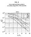
- Figure 3is a graph illustrating the bit error rates (BERs) and frame error rates (FERs) for (8, 8; 1) (uncoded) transmissions using 2-antenna scrambling transmission diversity 2TXS, 2-antenna baseline repeat diversity 2TXR, and 2-antenna receive diversity 2RX.
- BERsbit error rates
- FERsframe error rates
- Figure 4is a graph illustrating the bit error rates (BERs) and frame error rates (FERs) for (7, 4; 3) transmissions using 2-antenna scrambling transmission diversity 2TXS , 2-antenna baseline repeat diversity 2TXR, and 2-antenna receive diversity 2RX .
- BERsbit error rates
- FERsframe error rates
- Figure 5is a graph illustrating the bit error rates (BERs) and frame error rates (FERs) for (15, 5; 7) transmissions using 2-antenna scrambling transmission diversity 2TXS, 2-antenna baseline repeat diversity 2TXR, and 2-antenna receive diversity 2RX.
- BERsbit error rates
- FERsframe error rates
- Figure 6is a graph illustrating the bit error rates (BERs) and frame error rates (FERs) for (15, 7; 5) transmissions using 2-antenna scrambling transmission diversity 2TXS, 2-antenna baseline repeat diversity 2TXR, and 2-antenna receive diversity 2RX.
- BERsbit error rates
- FERsframe error rates
- Figure 7is a graph illustrating the bit error rates (BERs) and frame error rates (FERs) for (15, 11; 3) transmissions using 2-antenna scrambling transmission diversity 2TXS, 2-antenna baseline repeat diversity 2TXR, and 2-antenna receive diversity 2RX.
- BERsbit error rates
- FERsframe error rates
- Figure 8is a graph illustrating the bit error rates (BERs) and frame error rates (FERs) for (24, 12; 8) transmissions using 2-antenna scrambling transmission diversity 2TXS, 2-antenna baseline repeat diversity 2TXR, and 2-antenna receive diversity 2RX.
- BERsbit error rates
- FERsframe error rates
- error control codesare used to provide transmission diversity.
- transmission diversitycan be used to transmit from a base station so that most of the additional functionality needed to support the transmission diversity can be added at the base station. Because the mobile user terminals may be more constrained in terms of physical size, and power supply, and because there are typically many more user terminals than base stations, there are advantages to reducing the additional functionality added at the user terminal.
- the base stationincludes a processor 101, a plurality of encoders E 1 to E z , and a respective plurality of antennas A 1 to A z . While up to "Z" encoders and antennas are shown, the invention can be implemented with two encoders and antennas.
- Each of the antennas A 1 to A ztransmits to the user terminal 103 over a respective transmission path P 1 to P z .
- the user terminal 103includes a transceiver 105 and a processor 107. In general, the transceiver receives transmission from the base station antennas, and the processor processes the received transmissions.
- the user terminalcan be a mobile radiotelephone, a personal computer, a personal digital assistant or any other electronic device adapted for communications with the base station.
- the base station processor 101In a digital communications system, the base station processor 101 generates information words to be transmitted to the mobile station.
- each of the information wordsis chosen from a set of information words wherein each of the information words in the set has a predetermined length.
- An information wordis provided by the processor 101 to each of the encoders.
- Each encodermaps the received information word to a different code word chosen from a code word set wherein each code word in the set has a second predetermined length greater than the length of the information word.
- a plurality of different code wordsare then transmitted from respective antennas to the user terminal in response to a single information word. Because each code word is transmitted from a different antenna, each code word has a different path to the user terminal and will thus experience different fading characteristics.
- the code wordsare received at the user terminal transceiver 105 and provided to the user terminal processor 107 wherein the code words are decoded to provide an estimate of the original information word.
- each of the code wordscan be transmitted with a synchronization sequence unique to the encoder. Accordingly, each code word generated responsive to one information word is transmitted with a different synchronization sequence over a different path.
- the user terminal processor 107can thus use the synchronization sequences to resolve the fading along each of the transmission paths and thereby determine which code word came from which encoder.
- the code words corresponding to the information word provided to the encodersare transmitted concurrently from the respective antennas over a common frequency. Accordingly, the capacity of the system is not reduced as the duration of the transmission is not increased and the frequency use is not increased.
- the processorcan simultaneously decode the code words to estimate the original information word.
- Each of the encoders E 1 to E zmaps the information word to a different code word within the code word set based on a different generation matrix G 1 to G z .
- y 1x G 1
- y 2x G 2
- y zx G z
- the generator matricesare chosen such that the number of code words in the code word set is equal to the number of information words in the information word set, so that for each information word in the information word set, each generation matrix maps the information word to a different one of the code words.
- code words transmitted on different antennasare always distinct, and this property is referred to as scrambling diversity.
- an ( n , k; d ) binary linear block codeis defined where n is the code word length, k is the information word length, and d is the minimum Hamming distance, and each information word is provided to two encoders E 1 and E 2 .
- the encoder E 1maps the information to a first code word according the generator matrix G 1
- the encoder E 2maps the information word to a second code word according to the generator matrix G 2
- the generator matrices G 1 and G 2are distinct.
- y 2x G 2
- the code words y 1 and y 2are then transmitted concurrently from respective antennas A 1 and A 2 .
- the generator matrices for the encodersare chosen so that two distinct code words are generated for each of the information words provided thereto. In other words, the generator matrices are preferably chosen to maintain the scrambling property as discussed below.
- the precoder Fhas the scrambling property if: xF ⁇ x when x ⁇ 0, or equivalently if: y 1 ⁇ y 2 when x ⁇ 0.
- the scrambling propertyprovides that two distinct code words are generated for each information word. In other words, the code word pair will not collapse for any non-zero information word.
- the precoder F which provides the scrambling propertycan be obtained by a search.
- the precoder matrixcan be constructed as discussed below.
- This linear circuitincludes a shift register wherein the contents of the shift register change at every clock cycle.
- the shift registeris initialized with a non-zero m -tuple, the register will cycle through all 2 m - 1 distinct non-zero m -tuples before coming back to the original value.
- the current register contentscan thus be treated as the input, and the register contents during the following clock cycle can be the output.
- a scrambling matrix Fcan thus be generated having the form: where h 1 to h m are the taps of the circuit.
- This structure for the F matrixprovides for up to 2 k generator matrices for 2 k encoders transmitting from 2 k antennas.
- a first encodercan operate according to generator matrix G 1
- Simulationsindicate the transmission diversity techniques according to the present invention can be used for a (15, 5, 7) code at 1% bit error rate (BER) to provide two antenna transmit diversity with a 6.4 dB improvement in performance over no diversity, and only a 3 dB reduction in performance when compared with two antenna receive diversity.
- BERbit error rate
- the Hamming weight of yis denoted w( y ).
- the base stationincludes first and second encoders E 1 and E 2 operating according to respective generator matrices G 1 and G 2 as shown in Figure 1.
- the code words y 1 and y 2are then transmitted on respective first and second antennas A1 and A2.
- the transmission paths P1 and P2are assumed to follow a fading model wherein each code word is hit by a constant Rayleigh fade and wherein fades are independent from code word to code word and across antennas.
- the generator matrices G 1 and G 2 used in the encodersshould exhibit the scrambling property discussed above to provide the full advantages of transmit diversity.
- the precoder Fthus has the scrambling property if it satisfies: xF ⁇ x if x ⁇ 0, or equivalently if: y 1 ⁇ y 2 if x ⁇ 0.
- ⁇4(4 u + v 1 ) ⁇ 4 d
- the last inequalityfollows from equation (2)
- ⁇4 u ⁇ 4 d
- the inequalityfollows from equation (7).
- scrambling diversityshould provide improved performance because its worst case is not 0.
- the worst case for repeat diversitycan be 0.
- scrambling diversityprovides that the code word pair does not collapse (include the same two code words) as occurs with the repeat diversity situation of Case 3. Simulations confirm this result.
- the 2-antenna transmit diversity system discussed abovehas been simulated and the results are illustrated in the graphs of Figures 3-8.
- the data in each graph corresponding to a two antenna scrambled diversity system of the present inventionis indicated by the reference 2TXS.
- Data corresponding to a base line repeat diversity (no diversity) systemis indicated by the reference 2TXR
- data corresponding to a two antenna receive diversity systemis indicated by the reference 2RX for comparison.
- the datawas obtained using the following codes: (7, 4; 3), (15, 5; 7), (15, 7; 5), (15, 11; 3), and (24, 12; 8).
- datawas obtained for an uncoded 8 bit transmission (8, 8; 1).
- Table 1summarizes the gain ⁇ (dB) of transmit diversity over no diversity and the loss ⁇ (dB) of transmit diversity with respect to receive diversity, a 1% BER.
- code ⁇ ⁇ (8.8;1)4.8 3.4 (7, 4;3) 5.9 3.9 (15, 5;7) 6.4 2.9 (15, 7;5) 5.6 3.5 (15, 11;3) 5.7 2.8 (24, 12;8) 7.3 3.0
- transmission diversity methods, systems, and terminalscan be used with the D-AMPS + cellular communications protocol which is a higher throughput extension of the D-AMPS cellular communications protocol.
- the transmission diversity techniques of the present inventioncan also be used with other cellular communications protocols as well as non-cellular radio communications systems.
- diversity transmissionhas been discussed above with respect to binary block codes
- diversity transmission according to the present inventioncan also be applied to other codes.
- scrambling diversity transmissioncan be applied to binary convolution codes; non-binary block codes such as Reed-Solomon codes and BCH codes for the Lee metric; and non-binary trellis codes such as trellis coded modulation and dual-K codes.
Landscapes
- Engineering & Computer Science (AREA)
- Computer Networks & Wireless Communication (AREA)
- Signal Processing (AREA)
- Mobile Radio Communication Systems (AREA)
- Radio Transmission System (AREA)
- Radio Relay Systems (AREA)
Description
- The present invention relates to the field of communications and moreparticularly to diversity transmission systems and methods.
- Cellular communications systems are commonly employed to providevoice and data communications to a plurality of mobile units or subscribers.Analog cellular systems, such as designated AMPS, ETACS, NMT-450, andNMT-900, have been deployed successfully throughout the world. More recently,digital cellular systems such as designated IS-54B and IS-136 in North Americaand the pan-European GSM system have been introduced. These systems, andothers, are described, for example, in the book titledCellular Radio Systems byBalston, et al., published by Artech House, Norwood, MA., 1993.
- Frequency reuse is commonly employed in cellular technology whereingroups of frequencies are allocated for use in regions of limited geographiccoverage known as cells. Cells containing equivalent groups of frequencies aregeographically separated to allow mobile units in different cells to simultaneouslyuse the same frequency without interfering with each other. By so doing manythousands of subscribers may be served by a system of only several hundredfrequencies.
- In the United States, for example, Federal authorities have allocated tocellular communications a block of the UHF frequency spectrum furthersubdivided into pairs of narrow frequency bands called channels. Channelpairing results from the frequency duplex arrangement wherein the transmit andreceive frequencies in each pair are offset by 45 MHz. At present there are 832,30-KHz wide, radio channels allocated to cellular mobile communications in theUnited States. To address the capacity limitations of this analog system a digitaltransmission standard has been provided, designated IS-54B, wherein thesefrequency channels are further subdivided into time slots. The division of afrequency into a plurality of time slots wherein a channel is defined by afrequency and a time slot is known as time division multiple access (TDMA).
- As illustrated in FIG.1, a cellular communication system20 as in the priorart includes one or more mobile stations or units21, one or more base stations23 and a mobile telephone switching office (MTSO)25. Although only three cells36 are shown in FIG. 1, a typical cellular network may comprise hundreds of basestations, thousands of mobile stations and more than one MTSO. Each cell willhave allocated to it one or more dedicated control channels and one or morevoice channels. A typical cell may have, for example, one control channel, and21 voice/data, or traffic, channels. The control channel is a dedicated channelused for transmitting cell identification and paging information. The trafficchannels carry the voice and data information.
- The MTSO25 is the central coordinating element of the overall cellularnetwork20. It typically includes a cellular processor28, a cellular switch29 andalso provides the interface to the public switched telephone network (PSTN)30.Through the cellular network20, a duplex radio communication link32 may beeffected between two mobile stations21 or, between a mobile station21 and alandline telephone user33. The function of the base station23 is commonly tohandle the radio communication with the mobile station21. In this capacity, thebase station23 functions chiefly as a relay station for data and voice signals.The base station23 also supervises the quality of the link32 and monitors thereceived signal strength from the mobile station21.
- In a mobile communications system, signal performance my be reduceddue to signal fading occurring as a result of physical interference and motion ofthe mobile user terminal. Fading can be reduced, for example, by increasing transmitter power, antenna size, and antenna height These solutions,however, may be impractical and/or costly.
- Accordingly, multiple transmit antennas have been used to providetransmission diversity as discussed for example in the reference by Gueyet al. entitled "Signal Design for Transmission Diversity WirelessCommunication Systems Over Rayleigh Fading Channels." (ProceedingsIEEE VTC, 1996). If the antennas are placed far apart, each signal willexperience independent fading. This diversity can be made accessible tothe receiver by switching between the transmitters at different time instants.The peak to average power ratio of the transmitted signal may be greatlyincreased, however, and the output amplifier design may be complicated.
- Other transmission diversity techniques that do not switch betweentransmitters are ones using an intentional time offset or frequency offset,phase sweeping, frequency hopping, andlor modulation diversity. Most ofthese techniques use phase or frequency modulation of each transmittercarrier to induce intentional time-varying fading at the receiver. In addition,coded modulation schemes have been proposed to access the diversity ofa multiple transmitter system without using an interleaver.
- International Publication No. WO 97/41670 entitled "Method AndApparatus For Data Transmission Using Multiple Transmit Antennas"discusses a method and apparatus for increasing the data rate andproviding antenna diversity using multiple transmit antennas, (InternationalApplication No. PCT/US97/07010, published November 6,1997,) Thereference by All S. Khayrallah entitled "Precoding For Convolutional Codes"discusses distance relations between the input sequences and the codesequences in convolutional codes. (IEEE International Conference OnCommunications, Converging Technologies For Tomorrow's Applications,Dallas, June 23, 1996, pages 118-121, XP000625653.)
- Notwithstanding the transmission diversity techniques discussedabove, there continues to exist a need in the art for improved diversitymethods, systems, and terminals.
- It is therefore an object of the present invention to provide improvedcommunications methods, systems, and terminals.
- It is another object of the present invention to provide methods,systems, and terminals having improved transmission and reception.
- These and other objects are provided according to the presentinvention by methods and systems wherein an information word from aninformation word set is mapped to first and second code words andtransmitted. More particularly, the information word is mapped using firstand second mapping functions defined such that each of the informationwords of the information word set is mapped to two different code wordsthus providing scrambling transmission diversity. The two different code words can then be received and decoded jointly to provide anestimate of the information word.
- The scrambling transmission diversity according to the present inventionthus provides that all information words are scrambled into two distinct codewords from the code word set. Enhanced transmission and reception are thusprovided for all information words. By using scrambling transmission diversityaccording to the present invention in a communications system with mobile userterminals such as a cellular communications system, most of the additionalfunctionality can be added at the base station transmitters. Accordingly, littleadditional functionality is required at the mobile terminals where size and powerconsiderations may be more constraining.
- A method according to the present invention provides that an informationword is mapped to first and second code words using first and second mappingfunctions. In particular, the information word is selected from a set of informationwords with each of the information words in the information word set having a firstpredetermined length. Moreover, the first and second code words are selectedfrom a code word set with each of the code words in the set having a secondpredetermined length greater than the first predetermined length. The first andsecond mapping functions are defined such that each of the information words ofthe information word set are mapped to two different code words of the codeword set. The first and second code words are then transmitted.
- More particularly, the first and second code words can be transmitted fromfirst and second spaced apart antennas. The first and second code words can betransmitted concurrently over a common frequency. Accordingly, the first andsecond code words can be transmitted without impacting the transmissioncapacity.
- The first mapping function includes a first generator matrix wherein thefirst code word is equal to the first generator matrix times the information word,and the second mapping function includes a second generator matrix so thatthe second code word is equal to the second generator matrix times theinformation word. The first and second generator matrices are related by aprecoder such that the first generator matrix is equal to the precoder times thesecond generator matrix. In addition, the precoder can be constructed from theoutputs of a linear m-sequence generator.
- More particularly, a number of information words in the information wordset can be equal to a number of code words in the code word set. Theinformation word can also be mapped to a third code word using a third mappingfunction wherein the third code word is selected from the code word set.Moreover, the first, second, and third mapping functions are defined such thateach of the information words of the information word set are mapped to threedifferent code words of the code word set, and wherein the transmitting stepcomprises transmitting the first, second, and third code words.
- Methods and terminals are also provided for receiving informationtransmitted using code words as discussed above. In particular, the first andsecond code words are received and decoded to estimate the information word,and the first and second code words can be decoded simultaneously. Moreover,a first synchronization sequence can be transmitted with the first code word and asecond synchronization sequence can be transmitted with the second code word,and the first and second code words can be transmitted over first and secondpaths. Accordingly, the fading of the first and second paths can be resolvedusing the first and second synchronization sequences.
- The first and second code words can be transmitted concurrently andreceived concurrently, and the first and second code words can be transmittedover a common frequency. Moreover, the information word can be mapped to athird code word selected from the code word set, and the third code word can betransmitted. Accordingly, the receiving step can include receiving the first,second, and third code words, and the decoding step can include decoding thefirst, second, and third code words to estimate the information word.
- The scrambling diversity methods, systems, and terminals of the presentinvention thus provide improved radio communications over fadingcommunications channels. In particular, scrambling diversity transmission can beimplemented at a base station of a mobile communications system such as acellular communications system to provide improved communications. By addingmost of the functionality at the base station, the improved communications can beprovided without requiring significant additions to the mobile terminal where sizeand power considerations may be more constraining. Adding the functionality atthe base station also has the advantage that there are typically fewer basestations than there are mobile terminals.
- Figure1 is a schematic block diagram illustrating components of a cellularcommunications system according to the prior art.
- Figure 2 is a block diagram of a diversity transmission system according tothe present invention.
- Figure 3 is a graph illustrating the bit error rates (BERs) and frame errorrates (FERs) for (8, 8; 1) (uncoded) transmissions using 2-antenna scramblingtransmission diversity2TXS, 2-antenna baseline repeat diversity2TXR, and 2-antennareceive diversity2RX.
- Figure 4 is a graph illustrating the bit error rates (BERs) and frame errorrates (FERs) for (7, 4; 3) transmissions using 2-antenna scrambling transmissiondiversity2TXS, 2-antenna baseline repeat diversity 2TXR, and 2-antenna receivediversity2RX.
- Figure 5 is a graph illustrating the bit error rates (BERs) and frame errorrates (FERs) for (15, 5; 7) transmissions using 2-antenna scramblingtransmission diversity2TXS, 2-antenna baseline repeat diversity2TXR, and 2-antennareceive diversity2RX.
- Figure 6 is a graph illustrating the bit error rates (BERs) and frame errorrates (FERs) for (15, 7; 5) transmissions using 2-antenna scramblingtransmission diversity2TXS, 2-antenna baseline repeat diversity2TXR, and 2-antennareceive diversity2RX.
- Figure 7 is a graph illustrating the bit error rates (BERs) and frame errorrates (FERs) for (15, 11; 3) transmissions using 2-antenna scramblingtransmission diversity2TXS, 2-antenna baseline repeat diversity2TXR, and 2-antennareceive diversity2RX.
- Figure 8 is a graph illustrating the bit error rates (BERs) and frame errorrates (FERs) for (24, 12; 8) transmissions using 2-antenna scramblingtransmission diversity2TXS, 2-antenna baseline repeat diversity2TXR, and 2-antennareceive diversity2RX.
- The present invention will now be described more fully hereinafter withreference to the accompanying drawings, in which preferred embodiments of theinvention are shown. This invention may, however, be embodied in many different forms and should not be construed as limited to the embodiments setforth herein. Rather, these embodiments are provided so that this disclosure willbe thorough and complete, and will full convey the scope of the invention to thoseskilled in the art. Like numbers refer to like elements throughout.
- In a communications system according to the present invention, errorcontrol codes are used to provide transmission diversity. In a cellularcommunications system, transmission diversity can be used to transmit from abase station so that most of the additional functionality needed to support thetransmission diversity can be added at the base station. Because the mobileuser terminals may be more constrained in terms of physical size, and powersupply, and because there are typically many more user terminals than basestations, there are advantages to reducing the additional functionality added atthe user terminal.
- Elements of a cellular communications base station and a user terminalaccording to the present invention are illustrated in Figure 2. As shown, the basestation includes a processor101, a plurality of encodersE1 toEz, and arespective plurality of antennasA1 toAz. While up to"Z" encoders and antennasare shown, the invention can be implemented with two encoders and antennas.Each of the antennasA1 toAz transmits to the user terminal103 over arespective transmission pathP1 toPz. As shown, the user terminal103 includesa transceiver105 and a processor107. In general, the transceiver receivestransmission from the base station antennas, and the processor processes thereceived transmissions. The user terminal can be a mobile radiotelephone, apersonal computer, a personal digital assistant or any other electronic deviceadapted for communications with the base station.
- In a digital communications system, the base station processor101generates information words to be transmitted to the mobile station. In particular,each of the information words is chosen from a set of information words whereineach of the information words in the set has a predetermined length. In otherwords, each of the information words has a predetermined number of bitsk suchthat an information word can be represented asx = (x1, x2, ...xk) and such thatthere are 2k information words in the information word set.
- An information word is provided by the processor101 to each of theencoders. As shown, the base station can include up to "Z" encoders where Z =2k withk being the information word length. Diversity transmission according tothe present can be achieved, however, using two encoders and antennas. Eachencoder maps the received information word to a different code word chosenfrom a code word set wherein each code word in the set has a secondpredetermined length greater than the length of the information word. In otherwords, each of the code words has a predetermined number of bitsn such that acode word can be represented asy = (y1, y2, ... yn) whereinn is greater thank.
- A plurality of different code words are then transmitted from respectiveantennas to the user terminal in response to a single information word. Becauseeach code word is transmitted from a different antenna, each code word has adifferent path to the user terminal and will thus experience different fadingcharacteristics. The code words are received at the user terminal transceiver105and provided to the user terminal processor107 wherein the code words aredecoded to provide an estimate of the original information word.
- More particularly, each of the code words can be transmitted with asynchronization sequence unique to the encoder. Accordingly, each code wordgenerated responsive to one information word is transmitted with a differentsynchronization sequence over a different path. The user terminal processor107can thus use the synchronization sequences to resolve the fading along each ofthe transmission paths and thereby determine which code word came from whichencoder.
- The code words corresponding to the information word provided to theencoders are transmitted concurrently from the respective antennas over acommon frequency. Accordingly, the capacity of the system is not reduced asthe duration of the transmission is not increased and the frequency use is notincreased. In addition, the processor can simultaneously decode the code wordsto estimate the original information word.
- Each of the encodersE1 toEz maps the information word to a differentcode word within the code word set based on a different generation matrixG1 toGz. In other words,y1 =xG1,y2 =xG2, andyz =xGz. Moreover, the generatormatrices are chosen such that the number of code words in the code word set isequal to the number of information words in the information word set, so that for each information word in the information word set, each generation matrix mapsthe information word to a different one of the code words. In other words, codewords transmitted on different antennas are always distinct, and this property isreferred to as scrambling diversity.
- The mathematical properties and derivations of the transmit diversitygeneration matrices of the present invention will now be discussed in greaterdetail. In a two antenna diversity system, an (n,k; d) binary linear block code isdefined where n is the code word length,k is the information word length, and dis the minimum Hamming distance, and each information word is provided to twoencodersE1 andE2. The encoderE1 maps the information to a first code wordaccording the generator matrixG1, and the encoderE2 maps the informationword to a second code word according to the generator matrixG2, and thegenerator matricesG1 andG2 are distinct. An information wordx is thus mappedto two code words:
- The generator matrices for the encoders are chosen so that two distinctcode words are generated for each of the information words provided thereto. Inother words, the generator matrices are preferably chosen to maintain thescrambling property as discussed below. The generator matrices can be relatedusing a precoder F such that:
- The precoder F which provides the scrambling property can be obtainedby a search. Alternately, the precoder matrix can be constructed as discussedbelow. As will be understood by those having skill in the art, a linear circuit canbe used to generate an m-sequence withm =k. This linear circuit includes a shiftregister wherein the contents of the shift register change at every clock cycle. Inaddition, if the shift register is initialized with a non-zerom-tuple, the register willcycle through all 2m - 1 distinct non-zerom-tuples before coming back to theoriginal value. The current register contents can thus be treated as the input, andthe register contents during the following clock cycle can be the output. Ascrambling matrix F can thus be generated having the form:whereh1 tohm are the taps of the circuit.

- This structure for the F matrix provides for up to 2k generator matrices for2k encoders transmitting from 2k antennas. For example, a first encoder canoperate according to generator matrix G1, a second encoder can operateaccording to generator matrix G2 = FG1, a third encoder can operate according togenerator matrix G3 = F2G1, and an ith encoder can operate according togenerator matrix G1 = Fi-1 wherei ≤ 2k.
- Simulations indicate the transmission diversity techniques according to thepresent invention can be used for a (15, 5, 7) code at 1% bit error rate (BER) toprovide two antenna transmit diversity with a 6.4 dB improvement in performanceover no diversity, and only a 3 dB reduction in performance when compared withtwo antenna receive diversity.
- Diversity transmission, reception, and decoding will now be discussed ingreater detail for an (n,k;d) binary linear block code as discussed above. Again,a generator matrix G is used to map an information wordx=(x1, ... xk) to a codewordy = (y1, ... yn) such thaty =xG wherein the information wordx and the codewordy have binary components (0,1). The Hamming weight ofy is denotedw(y). For convenience, a code wordy can be treated as a bipolar vector (±1),which can be denoted Y, with components Y1 = 1 - 2yi.
- In a two antenna transmission diversity system, the base station includesfirst and second encodersE1 andE2 operating according to respective generatormatricesG1 andG2 as shown in Figure 1. The information wordx is mapped totwo code wordsy1 andy2 as shown below:
- The transmission pathsP1 andP2 are assumed to follow a fading modelwherein each code word is hit by a constant Rayleigh fade and wherein fades areindependent from code word to code word and across antennas. The receivedvector is thus:
- The maximum likelihood decoding rule is to find the pair (y1,y2)corresponding to some information wordx that reduces the norm of the errorvector:
- Because the code is linear, the case will be considered wherex = Q istransmitted with corresponding code wordsy1 =0 andy2 =0, or equivalently Y1 =+1 and Y2 = +1. The resulting error vector becomes:
- In the event that an error occurs, x ≠ 0. As a baseline, repeat diversity willbe considered wherein G1 = G2. Accordingly,
- The generator matrices G1 and G2 used in the encoders should exhibit thescrambling property discussed above to provide the full advantages of transmitdiversity. As previously discussed, G1 and G2 can be related using a precoder Fsuch that:
- The fading channel (α1, α2) will now be discussed for three cases ofinterest for code performance analysis. Actual performance will depend on thestatistics of (α1, α2) and v. Case 1 occurs when α1 = +1, and α2 = +1. In thiscase, for scrambling diversity:
- Case 2 occurs when α1 = +1, and α2 = 0. In this case, for scramblingdiversity:
- Case 3 occurs when α1 = +1, and α2 = -1. In this case, for scramblingdiversity:
- As the average performance of a code tends to be dominated by the worstcase, scrambling diversity should provide improved performance because itsworst case is not 0. The worst case for repeat diversity, however, can be 0. Inother words, scrambling diversity provides that the code word pair does notcollapse (include the same two code words) as occurs with the repeat diversitysituation of Case 3. Simulations confirm this result.
- The 2-antenna transmit diversity system discussed above has beensimulated and the results are illustrated in the graphs of Figures 3-8. Inparticular, the data in each graph corresponding to a two antenna scrambleddiversity system of the present invention is indicated by the reference2TXS.Data corresponding to a base line repeat diversity (no diversity) system isindicated by the reference2TXR, and data corresponding to a two antennareceive diversity system is indicated by the reference2RX for comparison. Thedata was obtained using the following codes: (7, 4; 3), (15, 5; 7), (15, 7; 5), (15,11; 3), and (24, 12; 8). In addition, data was obtained for an uncoded 8 bittransmission (8, 8; 1).
- The bit error rate (BER) and the frame or block error rate (FER) weremeasured, and the results are plotted in the graphs of Figures 3-8. The resultsare summarized in Table 1 which shows the gains of 2TXS over 2TXR, and theloss of 2TXS with respect to 2RX at 1% BER. For example, for a (15, 5; 7) code,2TXS is 6.4 dB better than 2TXR, and 3 dB worse than 2RX. In general, the FERresults show the same trend and favor 2TXS in the sense that it approaches2RX. The simulation results thus confirm the advantages of the scramblingdiversity of the present invention. Table 1 summarizes the gain γ(dB) of transmitdiversity over no diversity and the loss λ(dB) of transmit diversity with respect toreceive diversity, a 1% BER.
code γ λ (8.8;1) 4.8 3.4 (7, 4;3) 5.9 3.9 (15, 5;7) 6.4 2.9 (15, 7;5) 5.6 3.5 (15, 11;3) 5.7 2.8 (24, 12;8) 7.3 3.0 - The use of transmission diversity methods, systems, and terminalsaccording to the present invention can be used with the D-AMPS + cellularcommunications protocol which is a higher throughput extension of the D-AMPScellular communications protocol. The transmission diversity techniques of thepresent invention can also be used with other cellular communications protocolsas well as non-cellular radio communications systems.
- Although the encoding of the present invention has been discussed interms of a generator matrix representing a linear encoder, scrambling diversityaccording to the present inventioin can also be used with other encoders such asnon-linear encoders. For example, if g1(x) = y1 represents a first generally non-linearencoder, then a scrambling matrix F can be used to obtain a secondencoder g2(x) = g1(xF) = y2.
- While diversity transmission has been discussed above with respect tobinary block codes, diversity transmission according to the present invention canalso be applied to other codes. For example, scrambling diversity transmissioncan be applied to binary convolution codes; non-binary block codes such asReed-Solomon codes and BCH codes for the Lee metric; and non-binary trelliscodes such as trellis coded modulation and dual-K codes.
- Many modifications and other embodiments of the invention will come tothe mind of one skilled in the art having the benefit of the teachings presented inthe foregoing descriptions and the associated drawings. Therefore, it is to beunderstood that the invention is not limited to the specific embodiments disclosed, and that modifications and embodiments are intended to be includedwithin the scope of the appended claims.

Claims (42)
- A method of transmitting information comprising the steps ofmapping an infomation word to a first code word using a first mappingfunction, mapping said information word to a second code word using asecond mapping function, and transmitting the first and second codewords, said methodcharacterized by:said information word being selected from a set of informationwords, and said first code word being selected from a set of code words;said second code word being selected from said code wordset, and wherein said first and second mapping functions are defined suchthat each of said information words of said information word set aremapped to two different code words of said code word set; andsaid first mapping function comprising a first generator matrix (G1)such that said first code word is equal to said first generator matrix timessaid information word, and said second mapping function comprising asecond generator matrix (G2) so that said second code word is equal to saidsecond generator matrix times said information word wherein said first andsecond generator matrices are related by a precoder (F) such that the firstgenerator matrix is equal to the precoder times the second generatormatrix.
- A method according to Claim 1 wherein each of saidInformation words In said information word set has a first predeterminedlength and wherein each of said code words in said code word set has asecond predetermined length greater than said first predetermined length.
- A method according to Claim 1 wherein said transmitting stepcomprises transmitting said first code word from a first antenna andtransmitting said second code word from a second antenna.
- A method according to Claim 1 wherein said first and secondcode words are transmitted concurrently.
- A method according to Claim 4 wherein said first and secondcode words are transmitted over a common frequency.
- A method according to Claim 1 wherein said first code word istransmitted with a first synchronization sequence and said second codeword is transmitted with a second synchronization sequence different thanthe first synchronization sequence.
- A method according to Claim 1 wherein said precoder isconstructed from the outputs of a linearm-sequence generator.
- A method according to Claim 1 further comprising the stepsof:receiving said first and second code words at a user terminal;anddecoding said first and second code words at said userterminal to estimate said information word.
- A method according to Claim 1 wherein a number ofinformation words in said information word set is equai to a number of codewords in said code word set
- A method according to Claim 1 further comprising the step of:
mapping said information word to a third codeword using athird mapping function, wherein said third code word is selected from saidcode word set, and wherein said first, second, and third mapping functionsare defined such that each of said information words of said informationword set are mapped to three different code words of said code word set,and wherein said transmitting step comprises transmitting said first,second, and third code words. - A method according to Claim 1 wherein said first and secondmapping functions comprise linear mapping functions.
- A method according to Claim 1 wherein said first and secondmapping functions comprise non-linear mapping functions.
- A diversity transmission system for transmitting information,said diversity transmission system comprising a first encoder (E) which mapsan information word to a first code word using a first mapping function, asecond encoder (E2) which maps said information word to a second code wordusing a second mapping function, and a transmitter which transmits saidfirst and second code words, said systemcharacterized by:means adapted to select said information word from a set of informationwords, and means adapted to select said first code word from a set of code words;means adapted to select said second code word from said code wordset, and said first and second mapping functions being defined such thateach of said information words of said information word set are mapped totwo different code words of said code word set;said first mapping function comprising a first generator matrix (G1)such that said first code word is equal to said first generator matrix timessaid information word, and said second mapping function comprising asecond generator matrix (G2) so that said second code word is equal to saidsecond generator matrix times said information word; andsaid first and second generator matrices being related by aprecoder (F) such that the first generator matrix is equal to the precoder timesthe second generator matrix.
- A diversity transmission system according to Claim 13wherein each of said information words in said information word set has afirst predetermined length and wherein each of said code words in saidcode word set has a second predetermined length greater than said firstpredetermined length.
- A diversity transmission system according to Claim 13 furthercomprising first and second antennas (A1, A2) coupled to said transmitter whereinsaid first code word is transmitted from said first antenna (A1) and wherein saidsecond code word is transmitted from said second antenna (A2).
- A diversity transmission system according to Claim 13wherein said first and second code words are transmitted concurrently.
- A diversity transmission system according to Claim 16wherein said first and second code words are transmitted over a commonfrequency.
- A transmission system according to Claim 13 wherein saidtransmitter transmits said first code word with a first synchronizationsequence and said second code word with a second synchronizationsequence different than the first synchronization sequence.
- A diversity transmission system according to Claim 13wherein said precoder Is constructed from the outputs of a linearm-sequencegenerator.
- A diversity transmission system according to Claim 13wherein a number of information words in said information word set isequal to a number of code words in said code word set
- A diversity transmission system according to Claim 13 furthercomprising:
a third encoder (E3) which maps said information word to a thirdcode word using a third mapping function, wherein said third code word isselected from said code word set, and wherein said first, second, and thirdmapping functions are defined such that each of said information words ofsaid information word set are mapped to three different code words of said code word set, and wherein said transmitter transmits said first, second,and third code words. - A diversity transmission System according to Claim 13wherein said first and second mapping functions comprise linear mappingfunctions.
- A diversity transmission system according to Claim 13wherein said first and second mapping functions comprise non-linearmapping functions,
- A method of receiving information wherein an informationword is selected from an information word set, wherein the informationword is mapped to first and second code words selected from a code wordset using respective first and second mapping functions, and wherein thefirst and second code words are transmitted, sald method comprising thesteps of receiving the first and second code words, and decoding the firstand second code words to estimate the information word, said methodcharacterized by:said information word being selected from a set of informationwords, and said first code word being selected a set of code words;said second code word being selected from said code word set, andwherein said first and second mapping functions are defined such that eachof said Information words of said information word set are mapped to twodifferent code words of said code word set; andsaid first mapping function comprising a first generator matrix (G1) suchthat said first code word is equal to said first generator matrix times saidInformation word, and said second mapping function comprising a secondgenerator matrix (G2) so that said second code word is equal to said secondgenerator matrix times said information word wherein said first and secondgenerator matrices are related by a precoder such that the first generatormatrix Is equal to the precoder times the second generator matrix.
- A method according to Claim 24 wherein the first and secondcode words are decoded concurrently.
- A method according to Claim 24 wherein a firstsynchronization sequence is transmitted with the first code word and asecond synchronization sequence is transmitted with the second codeword, and wherein the first and second code words are transmitted overfirst and second paths, and wherein the first and second synchronizationsequences are different, said method comprising the steps of:receiving the first and second synchronization sequences;andresolving fading of the first and second paths using the firstand second synchronization sequences.
- A method according to Claim 24 wherein the first and secondcode words are transmitted concurrently, and wherein the first and secondcode words are received concurrently.
- A method according to Claim 27 wherein the first and secondcode words are transmitted over a common frequency.
- A method according to Claim 24 wherein the information wordis mapped to a third code word selected from the code word set andwherein the third code word is transmitted, wherein:said receiving step comprises receiving the first, second, andthird code words; andsaid decoding step comprises decoding the first, second, andthird code words to estimate the information word.
- A method according to Claim 24 wherein each of theinformation words in the information word set has a first predeterminedlength and wherein each of the code words in the code word set has asecond predetermined length greater than the first predetermined length.
- A method according to Claim 24 wherein the information wordis mapped to the first and second code words using linear mappingfunctions.
- A method according to Claim 24 wherein the information wordIs mapped to the first and second code words using non-linear mappingfunctions.
- A method according to Claim 24 wherein said precoder isconstructed from the outputs of a linearm-sequence generator.
- A user terminal for receiving information wherein anInformation word is selected from an information word set, wherein theinformation word is mapped to first and second code words selected from acode word set, and wherein the first and second code words aretransmitted, said user terminal comprising a receiver which receives thefirst and second code words, and a processor coupled to said receiverwherein said processor decodes the first and second code words toestimate the Information word, said user terminalcharacterized by:said information word being selected from a set of informationwords, and said first code word being selected from a set of code words;said second code word being selected from said code wordset, and said first and second mapping functions being defined such thateach of said information words of said information word set are mapped totwo different code words of said code word set;said first mapping function comprising a first generator matrix (G1)such that said first code word is equal to said first generator matrix timessaid information word, and said second mapping function comprising asecond generator matrix (G2) so that said second code word is equal to saidsecond generator matrix times said information word; andsaid first and second generator matrices being related by aprecoder (F) such that the first generator matrix is equal to the precoder timesthe second generator matrix.
- A user terminal according to Claim 34 wherein the first andsecond code words are decoded concurrently.
- A user terminal according to Claim 34 wherein a firstsynchronization sequence is transmitted with the first code word and asecond synchronization sequence is transmitted with the second codeword, wherein the first and second synchronization sequences aredifferent, and wherein the first and second code words are transmitted overfirst and second paths, wherein:said receiver receives the first and second synchronizationsequences; andsaid processor resolves fading of the first and second pathsusing the first and second synchronization sequences.
- A user terminal according to Claim 34 wherein the first andsecond code words are transmitted concurrently, and wherein:
said receiver receives the first and second code wordsconcurrently. - A user terminal according to Claim 37 wherein the first andsecond code words are transmitted over a common frequency, andwherein:
said receiver receives the first and second code words overthe common frequency. - A user terminal according to Claim 34 wherein each of theinformation words in the information word set has a first predeterminedlength and wherein each of the code words in the code word set has asecond predetermined length greater than the first predetermined length.
- A user terminal according to Claim 34 wherein the informationword is mapped to the first and second code words using a linear mappingfunction.
- A user terminal according to Claim 34 wherein the informationword is mapped to the first and second code words using a non-linearmapping function.
- A user terminal according to Claim 34 wherein said precoderis constructed from the outputs of a linearm-sequence generator,
Applications Claiming Priority (3)
| Application Number | Priority Date | Filing Date | Title |
|---|---|---|---|
| US67602 | 1998-04-28 | ||
| US09/067,602US6198775B1 (en) | 1998-04-28 | 1998-04-28 | Transmit diversity method, systems, and terminals using scramble coding |
| PCT/US1999/006872WO1999056406A1 (en) | 1998-04-28 | 1999-03-30 | Transmit diversity methods, systems, and terminals using scramble coding |
Publications (2)
| Publication Number | Publication Date |
|---|---|
| EP1075736A1 EP1075736A1 (en) | 2001-02-14 |
| EP1075736B1true EP1075736B1 (en) | 2001-12-19 |
Family
ID=22077136
Family Applications (1)
| Application Number | Title | Priority Date | Filing Date |
|---|---|---|---|
| EP99915107AExpired - LifetimeEP1075736B1 (en) | 1998-04-28 | 1999-03-30 | Transmit diversity methods, systems, and terminals using scramble coding |
Country Status (8)
| Country | Link |
|---|---|
| US (1) | US6198775B1 (en) |
| EP (1) | EP1075736B1 (en) |
| CN (1) | CN1307760A (en) |
| AU (1) | AU3370399A (en) |
| BR (1) | BRPI9909975B1 (en) |
| DE (1) | DE69900644T2 (en) |
| EE (1) | EE200000632A (en) |
| WO (1) | WO1999056406A1 (en) |
Families Citing this family (93)
| Publication number | Priority date | Publication date | Assignee | Title |
|---|---|---|---|---|
| US7215718B1 (en)* | 1999-04-28 | 2007-05-08 | At&T Corp. | Combined channel coding and space-time block coding in a multi-antenna arrangement |
| CN1342354A (en) | 1998-09-04 | 2002-03-27 | 美国电报电话公司 | Combined channel coding and space-block coding in multi-antenna arrangement |
| US6128330A (en) | 1998-11-24 | 2000-10-03 | Linex Technology, Inc. | Efficient shadow reduction antenna system for spread spectrum |
| US6298092B1 (en)* | 1999-12-15 | 2001-10-02 | Iospan Wireless, Inc. | Methods of controlling communication parameters of wireless systems |
| US6922445B1 (en)* | 1999-12-15 | 2005-07-26 | Intel Corporation | Method and system for mode adaptation in wireless communication |
| FI19992829A7 (en) | 1999-12-30 | 2001-07-01 | Nokia Networks Oy | Data transmission in a radio system from transmitter to receiver |
| US6658620B1 (en)* | 2000-01-11 | 2003-12-02 | Northrop Grumman Corporation | Burst and packet wireless transmission using product codes with iterative decoding |
| US6377632B1 (en) | 2000-01-24 | 2002-04-23 | Iospan Wireless, Inc. | Wireless communication system and method using stochastic space-time/frequency division multiplexing |
| US6442214B1 (en) | 2000-05-19 | 2002-08-27 | Iospan Wireless, Inc. | Diversity transmitter based on linear transform processing of transmitted information |
| US6539209B1 (en)* | 2000-05-30 | 2003-03-25 | Lucent Technologies Inc. | Code-division, multiple-access base station having transmit diversity |
| US7139324B1 (en)* | 2000-06-02 | 2006-11-21 | Nokia Networks Oy | Closed loop feedback system for improved down link performance |
| US6859643B1 (en)* | 2000-08-04 | 2005-02-22 | Lucent Technologies Inc. | Power amplifier sharing in a wireless communication system with amplifier pre-distortion |
| US6937592B1 (en) | 2000-09-01 | 2005-08-30 | Intel Corporation | Wireless communications system that supports multiple modes of operation |
| US9130810B2 (en) | 2000-09-13 | 2015-09-08 | Qualcomm Incorporated | OFDM communications methods and apparatus |
| US7295509B2 (en) | 2000-09-13 | 2007-11-13 | Qualcomm, Incorporated | Signaling method in an OFDM multiple access system |
| US6947505B2 (en)* | 2000-09-20 | 2005-09-20 | Bae Systems Information And Electronic Systems Integration Inc. | System for parameter estimation and tracking of interfering digitally modulated signals |
| US7058422B2 (en)* | 2000-09-20 | 2006-06-06 | Bae Systems Information And Electronic Systems Integration Inc. | Method for overusing frequencies to permit simultaneous transmission of signals from two or more users on the same frequency and time slot |
| US6567387B1 (en) | 2000-11-07 | 2003-05-20 | Intel Corporation | System and method for data transmission from multiple wireless base transceiver stations to a subscriber unit |
| US20020136287A1 (en)* | 2001-03-20 | 2002-09-26 | Heath Robert W. | Method, system and apparatus for displaying the quality of data transmissions in a wireless communication system |
| US6961545B2 (en)* | 2001-04-09 | 2005-11-01 | Atheros Communications, Inc. | Method and system for providing antenna diversity |
| US7200103B2 (en)* | 2001-06-21 | 2007-04-03 | Bae Systems Information And Electronic Systems Integration Inc. | Reduced algorithm receiver |
| US7139334B2 (en)* | 2001-06-21 | 2006-11-21 | Bartlett Alan M | Cooperative code-enhanced multi-user communications system |
| KR100400922B1 (en)* | 2001-07-21 | 2003-10-08 | 엘지전자 주식회사 | A circuit and a method of automatic control q for digital filter |
| US7149254B2 (en) | 2001-09-06 | 2006-12-12 | Intel Corporation | Transmit signal preprocessing based on transmit antennae correlations for multiple antennae systems |
| US20030067890A1 (en)* | 2001-10-10 | 2003-04-10 | Sandesh Goel | System and method for providing automatic re-transmission of wirelessly transmitted information |
| US7336719B2 (en)* | 2001-11-28 | 2008-02-26 | Intel Corporation | System and method for transmit diversity base upon transmission channel delay spread |
| US6839390B2 (en) | 2002-01-23 | 2005-01-04 | Bae Systems Information And Electronic Systems Integration Inc. | Voting system for improving the performance of single-user decoders within an iterative multi-user detection system |
| US6981203B2 (en)* | 2002-04-29 | 2005-12-27 | Bae Systems Information And Electronic Systems Integration Inc. | Method and apparatus for random shuffled turbo multiuser detector |
| US6947506B2 (en) | 2002-04-11 | 2005-09-20 | Bae Systems Information And Electronic Systems Integration Inc. | Method and apparatus for improved turbo multiuser detector |
| US7092464B2 (en)* | 2002-01-23 | 2006-08-15 | Bae Systems Information And Electronic Systems Integration Inc. | Multiuser detection with targeted error correction coding |
| US7190747B2 (en)* | 2002-03-25 | 2007-03-13 | Bae Systems Information And Electronic Systems Integration Inc. | Frequency mismatch compensation for multiuser detection |
| US7110439B2 (en)* | 2002-03-25 | 2006-09-19 | Bae Systems Information And Electronic Systems Integration Inc. | System for decreasing processing time in an iterative multi-user detector system |
| US7092452B2 (en)* | 2002-03-25 | 2006-08-15 | Bae Systems Information And Electronic Systems Integration Inc | Co-channel interference receiver |
| US6947502B2 (en)* | 2002-04-16 | 2005-09-20 | Taylor Matthew A | Parameter estimator for a multiuser detection receiver |
| US7012978B2 (en)* | 2002-03-26 | 2006-03-14 | Intel Corporation | Robust multiple chain receiver |
| CN100508423C (en)* | 2002-06-21 | 2009-07-01 | 诺基亚西门子通信有限责任两合公司 | A user positioning method in a wireless communication system using transmit diversity |
| US7190743B2 (en)* | 2002-07-29 | 2007-03-13 | Bae Systems Information And Electronic Systems Integration Inc. | Method and apparatus for optimizing tree pruning in a multiuser detector |
| US7126890B2 (en)* | 2002-08-26 | 2006-10-24 | Bae Systems Information And Electronic Systems Integration Inc | Multitrack readback and multiuser detection for disk drives |
| EP1933513B1 (en)* | 2003-12-17 | 2014-06-18 | QUALCOMM Incorporated | Method and transmitter for broadcast transmission with spatial spreading in a multi-antenna communication system |
| US8204149B2 (en) | 2003-12-17 | 2012-06-19 | Qualcomm Incorporated | Spatial spreading in a multi-antenna communication system |
| US7302009B2 (en) | 2003-12-17 | 2007-11-27 | Qualcomm Incorporated | Broadcast transmission with spatial spreading in a multi-antenna communication system |
| US7050768B2 (en)* | 2003-12-22 | 2006-05-23 | Texas Instruments Incorporated | Signal field controller, method of controlling and MIMO transmitter employing the same |
| US7336746B2 (en)* | 2004-12-09 | 2008-02-26 | Qualcomm Incorporated | Data transmission with spatial spreading in a MIMO communication system |
| US8169889B2 (en) | 2004-02-18 | 2012-05-01 | Qualcomm Incorporated | Transmit diversity and spatial spreading for an OFDM-based multi-antenna communication system |
| US20050180312A1 (en)* | 2004-02-18 | 2005-08-18 | Walton J. R. | Transmit diversity and spatial spreading for an OFDM-based multi-antenna communication system |
| US20050238111A1 (en)* | 2004-04-09 | 2005-10-27 | Wallace Mark S | Spatial processing with steering matrices for pseudo-random transmit steering in a multi-antenna communication system |
| US8923785B2 (en)* | 2004-05-07 | 2014-12-30 | Qualcomm Incorporated | Continuous beamforming for a MIMO-OFDM system |
| US8285226B2 (en)* | 2004-05-07 | 2012-10-09 | Qualcomm Incorporated | Steering diversity for an OFDM-based multi-antenna communication system |
| US20050265387A1 (en)* | 2004-06-01 | 2005-12-01 | Khojastepour Mohammad A | General code design for the relay channel and factor graph decoding |
| US7110463B2 (en)* | 2004-06-30 | 2006-09-19 | Qualcomm, Incorporated | Efficient computation of spatial filter matrices for steering transmit diversity in a MIMO communication system |
| US7978649B2 (en) | 2004-07-15 | 2011-07-12 | Qualcomm, Incorporated | Unified MIMO transmission and reception |
| US9148256B2 (en) | 2004-07-21 | 2015-09-29 | Qualcomm Incorporated | Performance based rank prediction for MIMO design |
| US9137822B2 (en) | 2004-07-21 | 2015-09-15 | Qualcomm Incorporated | Efficient signaling over access channel |
| US7978778B2 (en)* | 2004-09-03 | 2011-07-12 | Qualcomm, Incorporated | Receiver structures for spatial spreading with space-time or space-frequency transmit diversity |
| US7894548B2 (en)* | 2004-09-03 | 2011-02-22 | Qualcomm Incorporated | Spatial spreading with space-time and space-frequency transmit diversity schemes for a wireless communication system |
| US8009752B2 (en) | 2004-10-01 | 2011-08-30 | Qualcomm Incorporated | Multi-carrier incremental redundancy for packet-based wireless communications |
| US9246560B2 (en)* | 2005-03-10 | 2016-01-26 | Qualcomm Incorporated | Systems and methods for beamforming and rate control in a multi-input multi-output communication systems |
| US9154211B2 (en) | 2005-03-11 | 2015-10-06 | Qualcomm Incorporated | Systems and methods for beamforming feedback in multi antenna communication systems |
| US8446892B2 (en)* | 2005-03-16 | 2013-05-21 | Qualcomm Incorporated | Channel structures for a quasi-orthogonal multiple-access communication system |
| US9520972B2 (en) | 2005-03-17 | 2016-12-13 | Qualcomm Incorporated | Pilot signal transmission for an orthogonal frequency division wireless communication system |
| US9461859B2 (en)* | 2005-03-17 | 2016-10-04 | Qualcomm Incorporated | Pilot signal transmission for an orthogonal frequency division wireless communication system |
| US9143305B2 (en)* | 2005-03-17 | 2015-09-22 | Qualcomm Incorporated | Pilot signal transmission for an orthogonal frequency division wireless communication system |
| US9184870B2 (en)* | 2005-04-01 | 2015-11-10 | Qualcomm Incorporated | Systems and methods for control channel signaling |
| US9408220B2 (en) | 2005-04-19 | 2016-08-02 | Qualcomm Incorporated | Channel quality reporting for adaptive sectorization |
| US9036538B2 (en) | 2005-04-19 | 2015-05-19 | Qualcomm Incorporated | Frequency hopping design for single carrier FDMA systems |
| US8611284B2 (en) | 2005-05-31 | 2013-12-17 | Qualcomm Incorporated | Use of supplemental assignments to decrement resources |
| US8879511B2 (en) | 2005-10-27 | 2014-11-04 | Qualcomm Incorporated | Assignment acknowledgement for a wireless communication system |
| US8565194B2 (en) | 2005-10-27 | 2013-10-22 | Qualcomm Incorporated | Puncturing signaling channel for a wireless communication system |
| US8462859B2 (en)* | 2005-06-01 | 2013-06-11 | Qualcomm Incorporated | Sphere decoding apparatus |
| US8599945B2 (en) | 2005-06-16 | 2013-12-03 | Qualcomm Incorporated | Robust rank prediction for a MIMO system |
| US9179319B2 (en) | 2005-06-16 | 2015-11-03 | Qualcomm Incorporated | Adaptive sectorization in cellular systems |
| US8885628B2 (en) | 2005-08-08 | 2014-11-11 | Qualcomm Incorporated | Code division multiplexing in a single-carrier frequency division multiple access system |
| US7613228B2 (en)* | 2005-08-10 | 2009-11-03 | Bae Systems Information And Electronic Systems Integration Inc. | M-Algorithm multiuser detector with correlation based pruning |
| US9209956B2 (en) | 2005-08-22 | 2015-12-08 | Qualcomm Incorporated | Segment sensitive scheduling |
| US20070041457A1 (en)* | 2005-08-22 | 2007-02-22 | Tamer Kadous | Method and apparatus for providing antenna diversity in a wireless communication system |
| US8644292B2 (en)* | 2005-08-24 | 2014-02-04 | Qualcomm Incorporated | Varied transmission time intervals for wireless communication system |
| US9136974B2 (en)* | 2005-08-30 | 2015-09-15 | Qualcomm Incorporated | Precoding and SDMA support |
| US8582509B2 (en)* | 2005-10-27 | 2013-11-12 | Qualcomm Incorporated | Scalable frequency band operation in wireless communication systems |
| US8477684B2 (en)* | 2005-10-27 | 2013-07-02 | Qualcomm Incorporated | Acknowledgement of control messages in a wireless communication system |
| US9225416B2 (en) | 2005-10-27 | 2015-12-29 | Qualcomm Incorporated | Varied signaling channels for a reverse link in a wireless communication system |
| US9088384B2 (en)* | 2005-10-27 | 2015-07-21 | Qualcomm Incorporated | Pilot symbol transmission in wireless communication systems |
| US9225488B2 (en)* | 2005-10-27 | 2015-12-29 | Qualcomm Incorporated | Shared signaling channel |
| US9144060B2 (en) | 2005-10-27 | 2015-09-22 | Qualcomm Incorporated | Resource allocation for shared signaling channels |
| US8693405B2 (en) | 2005-10-27 | 2014-04-08 | Qualcomm Incorporated | SDMA resource management |
| US9210651B2 (en) | 2005-10-27 | 2015-12-08 | Qualcomm Incorporated | Method and apparatus for bootstraping information in a communication system |
| US9172453B2 (en) | 2005-10-27 | 2015-10-27 | Qualcomm Incorporated | Method and apparatus for pre-coding frequency division duplexing system |
| US8045512B2 (en) | 2005-10-27 | 2011-10-25 | Qualcomm Incorporated | Scalable frequency band operation in wireless communication systems |
| US8335272B2 (en) | 2005-10-28 | 2012-12-18 | Koninklijke Philips Electronics N.V. | Multiple antenna transmission with variable diversity gain |
| US8582548B2 (en) | 2005-11-18 | 2013-11-12 | Qualcomm Incorporated | Frequency division multiple access schemes for wireless communication |
| US8831607B2 (en) | 2006-01-05 | 2014-09-09 | Qualcomm Incorporated | Reverse link other sector communication |
| US8543070B2 (en) | 2006-04-24 | 2013-09-24 | Qualcomm Incorporated | Reduced complexity beam-steered MIMO OFDM system |
| US8290089B2 (en)* | 2006-05-22 | 2012-10-16 | Qualcomm Incorporated | Derivation and feedback of transmit steering matrix |
| US8677209B2 (en)* | 2009-11-19 | 2014-03-18 | Lsi Corporation | Subwords coding using different encoding/decoding matrices |
Family Cites Families (15)
| Publication number | Priority date | Publication date | Assignee | Title |
|---|---|---|---|---|
| US5479448A (en)* | 1992-03-31 | 1995-12-26 | At&T Corp. | Method and apparatus for providing antenna diversity |
| US5442626A (en)* | 1993-08-24 | 1995-08-15 | At&T Corp. | Digital communications system with symbol multiplexers |
| US5614914A (en)* | 1994-09-06 | 1997-03-25 | Interdigital Technology Corporation | Wireless telephone distribution system with time and space diversity transmission for determining receiver location |
| US5623485A (en)* | 1995-02-21 | 1997-04-22 | Lucent Technologies Inc. | Dual mode code division multiple access communication system and method |
| DE59610391D1 (en)* | 1995-06-12 | 2003-06-05 | Siemens Ag | Method and coding device for the secure transmission of data by means of multi-component coding |
| US5721745A (en)* | 1996-04-19 | 1998-02-24 | General Electric Company | Parallel concatenated tail-biting convolutional code and decoder therefor |
| EP2280494A3 (en) | 1996-04-26 | 2011-12-07 | AT & T Corp. | Method and apparatus for data transmission using multiple transmit antennas |
| US6023783A (en)* | 1996-05-15 | 2000-02-08 | California Institute Of Technology | Hybrid concatenated codes and iterative decoding |
| US5930230A (en)* | 1996-05-28 | 1999-07-27 | Qualcomm Incorporated | High data rate CDMA wireless communication system |
| US5790570A (en)* | 1996-08-30 | 1998-08-04 | Cornell Research Foundation, Inc. | Concatenated trellis coded modulation and linear block codes |
| US5832044A (en)* | 1996-09-27 | 1998-11-03 | Elvino S. Sousa | Transmitter antenna diversity and fading-resistant modulation for wireless communication systems |
| US5878085A (en)* | 1997-08-15 | 1999-03-02 | Sicom, Inc. | Trellis coded modulation communications using pilot bits to resolve phase ambiguities |
| US5946328A (en)* | 1997-11-17 | 1999-08-31 | International Business Machines Corporation | Method and means for efficient error detection and correction in long byte strings using integrated interleaved Reed-Solomon codewords |
| US6005897A (en)* | 1997-12-16 | 1999-12-21 | Mccallister; Ronald D. | Data communication system and method therefor |
| US6088387A (en)* | 1997-12-31 | 2000-07-11 | At&T Corp. | Multi-channel parallel/serial concatenated convolutional codes and trellis coded modulation encoder/decoder |
- 1998
- 1998-04-28USUS09/067,602patent/US6198775B1/ennot_activeExpired - Lifetime
- 1999
- 1999-03-30EPEP99915107Apatent/EP1075736B1/ennot_activeExpired - Lifetime
- 1999-03-30BRBRPI9909975Apatent/BRPI9909975B1/ennot_activeIP Right Cessation
- 1999-03-30EEEEP200000632Apatent/EE200000632A/enunknown
- 1999-03-30DEDE69900644Tpatent/DE69900644T2/ennot_activeExpired - Lifetime
- 1999-03-30WOPCT/US1999/006872patent/WO1999056406A1/enactiveIP Right Grant
- 1999-03-30CNCN99808000Apatent/CN1307760A/enactivePending
- 1999-03-30AUAU33703/99Apatent/AU3370399A/ennot_activeAbandoned
Also Published As
| Publication number | Publication date |
|---|---|
| CN1307760A (en) | 2001-08-08 |
| DE69900644D1 (en) | 2002-01-31 |
| EE200000632A (en) | 2002-02-15 |
| BRPI9909975B1 (en) | 2015-09-29 |
| US6198775B1 (en) | 2001-03-06 |
| BR9909975A (en) | 2000-12-26 |
| EP1075736A1 (en) | 2001-02-14 |
| AU3370399A (en) | 1999-11-16 |
| DE69900644T2 (en) | 2002-08-08 |
| WO1999056406A1 (en) | 1999-11-04 |
Similar Documents
| Publication | Publication Date | Title |
|---|---|---|
| EP1075736B1 (en) | Transmit diversity methods, systems, and terminals using scramble coding | |
| KR100354994B1 (en) | Systems and Methods for Data Extension Pilot Symbol Supported Wireless Telephone Communications | |
| EP1792429B1 (en) | Advanced mimo interleaving | |
| US8418033B2 (en) | Mode selection for data transmission in wireless communication channels based on statistical parameters | |
| CN101300878B (en) | Data transmission device and method in communication system | |
| Fengler et al. | Grant-free massive random access with a massive MIMO receiver | |
| US7230928B2 (en) | Data transfer method | |
| EP0820659A1 (en) | Data transmission method, and transmitter | |
| JP2000501254A (en) | Highly transparent transmission method for wireless communication systems | |
| WO2002047278A2 (en) | Simple block space time transmit diversity using multiple spreading codes | |
| EP2041887B1 (en) | Enabling mobile switched antennas | |
| KR20040111460A (en) | Data channel procedure for systems employing frequency diversity | |
| Yang et al. | Linear physical-layer network coding and information combining for the $ K $-user fading multiple-access relay network | |
| US6865373B2 (en) | Apparatus and method for encoding and decoding data within wireless networks | |
| CN101990268B (en) | Method, system and device for switching antenna modes | |
| EP1091517A1 (en) | Communication method and apparatus using punctured or repeated data | |
| JP3662321B2 (en) | Mobile communication device | |
| US20050095997A1 (en) | Transmit diversity gain for wireless communications networks | |
| KR100586858B1 (en) | Ultra Wideband Communication System and Method with Multiple Antennas | |
| Dash et al. | Performance evaluation of coding schemes for 5G Communication under different channel setting | |
| JP2006514520A (en) | Data coding for static MIMO channels | |
| Tarokh et al. | Low-rate multi-dimensional space-time codes for both slow and rapid fading channels | |
| CN1520668A (en) | Adaptive Symbol Transformation in Mobile Systems | |
| Aguerri et al. | Partial compute-compress-and-forward for limited backhaul uplink multicell processing | |
| Denno et al. | Cyclic path switching for lattice reduction-aided iterative linear receivers in overloaded MIMO systems |
Legal Events
| Date | Code | Title | Description |
|---|---|---|---|
| PUAI | Public reference made under article 153(3) epc to a published international application that has entered the european phase | Free format text:ORIGINAL CODE: 0009012 | |
| 17P | Request for examination filed | Effective date:20001120 | |
| AK | Designated contracting states | Kind code of ref document:A1 Designated state(s):BE DE ES FI FR GB SE | |
| GRAG | Despatch of communication of intention to grant | Free format text:ORIGINAL CODE: EPIDOS AGRA | |
| 17Q | First examination report despatched | Effective date:20010418 | |
| GRAG | Despatch of communication of intention to grant | Free format text:ORIGINAL CODE: EPIDOS AGRA | |
| GRAH | Despatch of communication of intention to grant a patent | Free format text:ORIGINAL CODE: EPIDOS IGRA | |
| GRAH | Despatch of communication of intention to grant a patent | Free format text:ORIGINAL CODE: EPIDOS IGRA | |
| GRAA | (expected) grant | Free format text:ORIGINAL CODE: 0009210 | |
| AK | Designated contracting states | Kind code of ref document:B1 Designated state(s):BE DE ES FI FR GB SE | |
| PG25 | Lapsed in a contracting state [announced via postgrant information from national office to epo] | Ref country code:FI Free format text:LAPSE BECAUSE OF FAILURE TO SUBMIT A TRANSLATION OF THE DESCRIPTION OR TO PAY THE FEE WITHIN THE PRESCRIBED TIME-LIMIT Effective date:20011219 Ref country code:BE Free format text:LAPSE BECAUSE OF FAILURE TO SUBMIT A TRANSLATION OF THE DESCRIPTION OR TO PAY THE FEE WITHIN THE PRESCRIBED TIME-LIMIT Effective date:20011219 | |
| REG | Reference to a national code | Ref country code:GB Ref legal event code:IF02 | |
| REF | Corresponds to: | Ref document number:69900644 Country of ref document:DE Date of ref document:20020131 | |
| PG25 | Lapsed in a contracting state [announced via postgrant information from national office to epo] | Ref country code:SE Free format text:LAPSE BECAUSE OF FAILURE TO SUBMIT A TRANSLATION OF THE DESCRIPTION OR TO PAY THE FEE WITHIN THE PRESCRIBED TIME-LIMIT Effective date:20020319 | |
| PG25 | Lapsed in a contracting state [announced via postgrant information from national office to epo] | Ref country code:ES Free format text:LAPSE BECAUSE OF FAILURE TO SUBMIT A TRANSLATION OF THE DESCRIPTION OR TO PAY THE FEE WITHIN THE PRESCRIBED TIME-LIMIT Effective date:20020627 | |
| PLBE | No opposition filed within time limit | Free format text:ORIGINAL CODE: 0009261 | |
| STAA | Information on the status of an ep patent application or granted ep patent | Free format text:STATUS: NO OPPOSITION FILED WITHIN TIME LIMIT | |
| 26N | No opposition filed | ||
| PGFP | Annual fee paid to national office [announced via postgrant information from national office to epo] | Ref country code:FR Payment date:20060317 Year of fee payment:8 | |
| REG | Reference to a national code | Ref country code:FR Ref legal event code:ST Effective date:20071130 | |
| PG25 | Lapsed in a contracting state [announced via postgrant information from national office to epo] | Ref country code:FR Free format text:LAPSE BECAUSE OF NON-PAYMENT OF DUE FEES Effective date:20070402 | |
| PGFP | Annual fee paid to national office [announced via postgrant information from national office to epo] | Ref country code:GB Payment date:20180327 Year of fee payment:20 | |
| PGFP | Annual fee paid to national office [announced via postgrant information from national office to epo] | Ref country code:DE Payment date:20180328 Year of fee payment:20 | |
| REG | Reference to a national code | Ref country code:DE Ref legal event code:R071 Ref document number:69900644 Country of ref document:DE | |
| REG | Reference to a national code | Ref country code:GB Ref legal event code:PE20 Expiry date:20190329 | |
| PG25 | Lapsed in a contracting state [announced via postgrant information from national office to epo] | Ref country code:GB Free format text:LAPSE BECAUSE OF EXPIRATION OF PROTECTION Effective date:20190329 |