EP1075091A1 - Method, circuit and system for operation of a low voltage network for data transmission in an energy distribution - Google Patents
Method, circuit and system for operation of a low voltage network for data transmission in an energy distributionDownload PDFInfo
- Publication number
- EP1075091A1 EP1075091A1EP00115738AEP00115738AEP1075091A1EP 1075091 A1EP1075091 A1EP 1075091A1EP 00115738 AEP00115738 AEP 00115738AEP 00115738 AEP00115738 AEP 00115738AEP 1075091 A1EP1075091 A1EP 1075091A1
- Authority
- EP
- European Patent Office
- Prior art keywords
- circuit
- conditioning
- impedance
- terminating
- circuit according
- Prior art date
- Legal status (The legal status is an assumption and is not a legal conclusion. Google has not performed a legal analysis and makes no representation as to the accuracy of the status listed.)
- Withdrawn
Links
- 230000005540biological transmissionEffects0.000titleclaimsabstractdescription15
- 238000000034methodMethods0.000titleclaimsabstractdescription14
- 230000003750conditioning effectEffects0.000claimsabstractdescription22
- 230000008878couplingEffects0.000claimsabstractdescription9
- 238000010168coupling processMethods0.000claimsabstractdescription9
- 238000005859coupling reactionMethods0.000claimsabstractdescription9
- 230000007935neutral effectEffects0.000claimsabstractdescription9
- 239000004020conductorSubstances0.000claimsdescription16
- 230000006978adaptationEffects0.000claimsdescription5
- 230000003595spectral effectEffects0.000claimsdescription2
- 239000003990capacitorSubstances0.000abstract1
- 238000013461designMethods0.000description2
- 230000005611electricityEffects0.000description2
- 238000012546transferMethods0.000description2
- 238000004891communicationMethods0.000description1
- 230000000295complement effectEffects0.000description1
- 230000001143conditioned effectEffects0.000description1
- 238000011156evaluationMethods0.000description1
- 230000002265preventionEffects0.000description1
- 230000001105regulatory effectEffects0.000description1
- 230000008054signal transmissionEffects0.000description1
Images
Classifications
- H—ELECTRICITY
- H04—ELECTRIC COMMUNICATION TECHNIQUE
- H04B—TRANSMISSION
- H04B3/00—Line transmission systems
- H04B3/54—Systems for transmission via power distribution lines
- H04B3/56—Circuits for coupling, blocking, or by-passing of signals
- H—ELECTRICITY
- H04—ELECTRIC COMMUNICATION TECHNIQUE
- H04B—TRANSMISSION
- H04B2203/00—Indexing scheme relating to line transmission systems
- H04B2203/54—Aspects of powerline communications not already covered by H04B3/54 and its subgroups
- H04B2203/5404—Methods of transmitting or receiving signals via power distribution lines
- H04B2203/5425—Methods of transmitting or receiving signals via power distribution lines improving S/N by matching impedance, noise reduction, gain control
- H—ELECTRICITY
- H04—ELECTRIC COMMUNICATION TECHNIQUE
- H04B—TRANSMISSION
- H04B2203/00—Indexing scheme relating to line transmission systems
- H04B2203/54—Aspects of powerline communications not already covered by H04B3/54 and its subgroups
- H04B2203/5429—Applications for powerline communications
- H04B2203/5445—Local network
- H—ELECTRICITY
- H04—ELECTRIC COMMUNICATION TECHNIQUE
- H04B—TRANSMISSION
- H04B2203/00—Indexing scheme relating to line transmission systems
- H04B2203/54—Aspects of powerline communications not already covered by H04B3/54 and its subgroups
- H04B2203/5462—Systems for power line communications
- H04B2203/5466—Systems for power line communications using three phases conductors
- H—ELECTRICITY
- H04—ELECTRIC COMMUNICATION TECHNIQUE
- H04B—TRANSMISSION
- H04B2203/00—Indexing scheme relating to line transmission systems
- H04B2203/54—Aspects of powerline communications not already covered by H04B3/54 and its subgroups
- H04B2203/5462—Systems for power line communications
- H04B2203/5483—Systems for power line communications using coupling circuits
Definitions
- the inventionrelates to a method for operating of low-voltage networks provided as an energy distribution network for data transmission, with conditioning of the network he follows.
- the inventionalso relates to the associated one Circuit for executing the method and on a related arrangement with such a circuit.
- the latter high-frequency signalscan be found in the existing ones Only very limited transmission of power distribution networks: On the one hand, there is the electrical resistance of the low-voltage network for the high frequency signals higher and on the other hand especially hinder reflection and refraction of the high-frequency signals at connection and Branch points and at the open ends of the lines Signal propagation. In addition, these signals are transmitted through the low-voltage network connected consumers disturbed.
- the object of the inventionis to take suitable measures to specify for conditioning that does not increase Lead power loss in the energy distribution network.
- the objectis achieved in that for conditioning of the energy distribution network only impedances can be used in the cross branch. Can advantageously such impedances can be selected in which an adaptation to the respective needs is possible, reducing the impedances in the cross branch of the network advantageously while running Operation can be adapted.
- the inventionensures that the power loss is not increased in the energy distribution network because the conditioning measures always across the ladder in the form of so-called Conditioning circuits are attached. Are preferred in such circuits, three terminating resistors due to coupling capacitances between the outer conductors of the low-voltage network and the neutral conductor available.
- the conditioning circuitsonly with passive Components are executed.
- a conditioning circuitit makes sense to do this in each case to be arranged in its own housing.
- Such housingscan for example, be attached to a top-hat rail and thus can be easily installed in control cabinets.
- Unitscan be combined and adapted with such circuits.
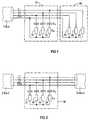
- Line 1denotes a three-phase line with characteristic impedance Z W.
- Line 1consists of individual phase conductors L1, L2, L3 and a neutral conductor PEN.
- a three-phase load in the low-voltage networkis to be connected to line 1 with characteristic impedance Z W , which is generally referred to as 20 with resistors 21, 22, 23.
- a conditioning circuitis provided, which is designed as a unit 10 with a terminating impedance.
- three terminating resistors 11, 12, 13are connected between the outer conductors L1, L2 and L3 and the neutral conductor PEN via coupling capacitances C K.
- the terminating resistors 11, 12, 13do not necessarily have to be purely ohmic resistors, but rather can each represent a complex impedance Z W , which corresponds to the characteristic impedance of the lead 1.
- the coupling capacitances C Kare preferably at most a few 100 nFd, so that the mains frequency voltage is effectively kept away from the terminating resistors 11, 12, 13, whereas the carrier frequency voltage of the signal can pass largely unimpeded.
- a first line with characteristic impedance Z W1is again designated 1, which consists of the phase conductors L1, L2, L3 and the neutral conductor PEN.
- a second line with phase conductors L1, L2, L3 and neutral conductor PENis designated 2 here and has the characteristic impedance Z W2 .
- the coupling capacitiesare some 100 nFd.
- the amount of the matching impedances Z awill preferably be between those of the wave resistances Z W1 and Z W2 of the lines 1 and 2 to be connected.
- circuits described with reference to Figures 1 and 2can for the practical application of the conditioning of Power distribution networks arranged in a separate housing be, for example, with other switching units a moving top-hat rail can be lined up and so easily in Control cabinets can be installed. It is also possible, the circuits as a technical unit with existing ones Switchgear, such as circuit breakers, residual current circuit breakers or the like to combine. After all it is possible the circuit in a connector housing or in the form a socket adapter to provide as an adapter. Such plugs can, for example, on the house connection box be arranged.
Landscapes
- Engineering & Computer Science (AREA)
- Power Engineering (AREA)
- Computer Networks & Wireless Communication (AREA)
- Signal Processing (AREA)
- Cable Transmission Systems, Equalization Of Radio And Reduction Of Echo (AREA)
Abstract
Description
Translated fromGermanDie Erfindung bezieht sich auf ein Verfahren zum Betreibenvon als Energieverteilnetz vorgesehenen Niederspannungsnetzenzur Datenübertragung, wobei eine Konditionierung des Netzeserfolgt. Daneben bezieht sich die Erfindung auch auf die zugehörigeSchaltung zur Ausführung des Verfahrens und auf einediesbezügliche Anordnung mit einer solchen Schaltung.The invention relates to a method for operatingof low-voltage networks provided as an energy distribution networkfor data transmission, with conditioning of the networkhe follows. In addition, the invention also relates to the associated oneCircuit for executing the method and on arelated arrangement with such a circuit.
Die Übertragung von Daten auf Energieleitungen, die in derFachwelt als PLC (PowerLineCommunication) bezeichnet wird,gewinnt in der technischen Diskussion zunehmend an Bedeutung.Allerdings sind insbesondere die in der Praxis vorhandenenNiederspannungsnetze nicht zur Übertragung von Daten, sondernvielmehr für die Übertragung von Energie in Form niederfrequenterStröme und Spannungen, d.h. im Bereich von 50 bzw.60 Hz, ausgelegt. Um praktisch relevante Übertragungsdatenerzielen zu können, sind hingegen höhere Frequenzen, vorzugsweiseim Bereich von einigen kHz bis in den MHz-Bereich, notwendig.The transmission of data on power lines, which is referred to in the art as a PLC(P owerL ineC ommunication), wins in the technical discussion increasingly important. However, the low-voltage networks available in practice are not designed for the transmission of data, but rather for the transmission of energy in the form of low-frequency currents and voltages, ie in the range of 50 or 60 Hz. In order to be able to achieve practically relevant transmission data, on the other hand, higher frequencies, preferably in the range from a few kHz to the MHz range, are necessary.
Letztere hochfrequenten Signale lassen sich in den vorhandenenEnergieverteilungsnetzen nur sehr eingeschränkt übertragen:Einerseits ist der elektrische Widerstand des Niederspannungsnetzesfür die hochfrequenten Signale höher und andererseitsbehindern speziell Reflexions- und Brechungserscheinungender hochfrequenten Signale an Verbindungs- undAbzweigstellen sowie an den offenen Enden der Leitungen dieSignalausbreitung. Daneben werden diese Signale durch am Niederspannungsnetzangeschlossene Verbraucher gestört.The latter high-frequency signals can be found in the existing onesOnly very limited transmission of power distribution networks:On the one hand, there is the electrical resistance of the low-voltage networkfor the high frequency signals higher and on the other handespecially hinder reflection and refractionof the high-frequency signals at connection andBranch points and at the open ends of the linesSignal propagation. In addition, these signals are transmitted through the low-voltage networkconnected consumers disturbed.
Um eine industrielle Datenübertragung auf Energieverteilnetzenzu ermöglichen sind verschiedene Strategien möglich, die sich unter Umständen ergänzen können: Grundsätzlich müssenstörsichere Übertragungs- bzw. Modulationsverfahren angewendetwerden. Weiterhin muss die Sendeleistung erhöht werden.Schließlich müssen die Signalübertragungseigenschaften desEnergienetz verbessert werden, was unter dem Begriff der sogenanntenKonditionierung zusammengefasst wird.For industrial data transmission on energy distribution networksDifferent strategies are possible to make thecan complement each other under certain circumstances: In principle, mustinterference-free transmission or modulation methods appliedbecome. The transmission power must also be increased.Finally, the signal transmission properties of theEnergy network can be improved, what is called the so-calledConditioning is summarized.
In den Zeitschriften-Veröffentlichungen
Daten imStrom" aus c't (1998), Heft 11, Seiten 174 bis 180 werden bereitseine Reihe von allgemeinen Hinweisen für eine industrielleNutzung der PLC, mit denen Niederspannungsnetze fürdie Übertragung von Daten ertüchtigt bzw. konditioniert werdenkönnen, gegeben. Konkrete schaltungstechnische Realisierungsvorschlägesind dort allerdings nicht angegeben.In the magazine publications
Data in the stream "from c't (1998),
Stand der Technik ist, dass Leitungen, die ausschließlich zurÜbertragung von Daten vorgesehen und geeignet sind, bestimmtenAnforderungen wie Verzerrungsfreiheit, Verhinderung vonReflexionen an den Leitungsenden, beispielsweise durch Abschlusswiderständeod. dgl., genügen müssen. Daneben ist esvom Stand der Technik auch bekannt, Netzabschnitte des Energieverteilnetzes,die zur Übertragung von Daten vorgesehensind, durch Filterschaltungen gegen Störungen aus anderenNetzabschnitten zu schützen sowie das Abfließen der Signalleistungdes Trägersignals zu verhindern. Solche Filterkreiseenthalten Impedanzen, vorzugsweise Induktivitäten, in Längsrichtung,welche in Verbindung mit dem betriebsmäßigennetzfrequenten Strom zu hohen Verlusten führen.State of the art is that lines that are used exclusively forTransfer of data is provided and suitable, certainRequirements such as freedom from distortion, prevention ofReflections at the cable ends, for example due to terminating resistorsor the like, must suffice. It is next to italso known from the prior art, network sections of the energy distribution network,provided for the transmission of dataare, by filter circuits against interference from othersProtect network sections and drain the signal powerto prevent the carrier signal. Such filter circlescontain impedances, preferably inductors, in the longitudinal direction,which in connection with the operationalmains frequency electricity lead to high losses.
Aufgabe der Erfindung ist es demgegenüber, geeignete Maßnahmenzur Konditionierung anzugeben, die nicht zur Erhöhung derVerlustleistung im Energieverteilnetz führen.In contrast, the object of the invention is to take suitable measuresto specify for conditioning that does not increaseLead power loss in the energy distribution network.
Die Aufgabe ist erfindungsgemäß dadurch gelöst, dass zur Konditionierungdes Energieverteilnetzes ausschließlich Impedanzenim Querzweig verwendet werden. Vorteilhafterweise können solche Impedanzen gewählt werden, bei denen eine Anpassung andie jeweiligen Bedürfnisse möglich ist, wodurch die Impedanzenim Querzweig des Netzes vorteilhafterweise bei laufendemBetrieb adaptiert werden können.The object is achieved in that for conditioningof the energy distribution network only impedancescan be used in the cross branch. Can advantageouslysuch impedances can be selected in which an adaptation tothe respective needs is possible, reducing the impedancesin the cross branch of the network advantageously while runningOperation can be adapted.
Mit der Erfindung wird gewährleistet, dass die Verlustleistungim Energieverteilnetz nicht erhöht wird, da die Konditioniermaßnahmenimmer quer zu den Leitern in Form sogenannterKonditionierschaltungen angebracht werden. Vorzugsweise sindbei solchen Schaltungen drei Abschlusswiderstände durch Koppelkapazitätenzwischen den Außenleitern des Niederspannungsnetzesund dem Neutralleiter vorhanden.The invention ensures that the power lossis not increased in the energy distribution network because the conditioning measuresalways across the ladder in the form of so-calledConditioning circuits are attached. Are preferredin such circuits, three terminating resistors due to coupling capacitancesbetween the outer conductors of the low-voltage networkand the neutral conductor available.
Bei der Erfindung kann es aus Kostengründen vorteilhaft sein,wenn die Konditionierschaltungen ausschließlich mit passivenBauelementen ausgeführt sind. Für die praktische Anwendungeiner Konditionier-Schaltung ist es sinnvoll, diese jeweilsin einem eigenen Gehäuse anzuordnen. Solche Gehäuse könnenbeispielsweise auf einer Hutschiene angebracht sein und somitleicht in Schaltschränke eingebaut werden. Es sind auch andereEinheiten mit solchen Schaltungen kombinierbar und adaptierbar.In the case of the invention, it can be advantageous for cost reasonsif the conditioning circuits only with passiveComponents are executed. For practical usea conditioning circuit, it makes sense to do this in each caseto be arranged in its own housing. Such housings canfor example, be attached to a top-hat rail and thuscan be easily installed in control cabinets. There are others tooUnits can be combined and adapted with such circuits.
Weitere Einzelheiten und Vorteile der Erfindung ergeben sichaus der nachfolgenden Figurenbeschreibung von Ausführungsbeispielenanhand der Zeichnung in Verbindung mit weiteren Patentansprüchen.Es zeigen
Figur 1- die schaltungsmäßige Gestaltung einer Abschlussimpedanzzur Verwendung bei PLC und
Figur 2- die schaltungsmäßige Gestaltung einer Anpass-Impedanzzur Kopplung von Niederspannungsleitungen mit unterschiedlichemWellenwiderstand.
- Figure 1
- the circuit design of a termination impedance for use with PLC and
- Figure 2
- the circuit design of a matching impedance for coupling low-voltage lines with different characteristic impedance.
Gleiche bzw. gleichwirkende Einheiten haben in den Figurengleiche Bezugszeichen.The same or equivalent units have in the figuressame reference numerals.
In Figur 1 ist mit 1 eine dreiphasige Leitung mit WellenwiderstandZW bezeichnet. Die Leitung 1 besteht aus einzelnenPhasenleitern L1, L2, L3 und einem Neutralleiter PEN.In Figure 1, 1 denotes a three-phase line with characteristic impedance ZW. Line 1 consists of individual phase conductors L1, L2, L3 and a neutral conductor PEN.
An die Leitung 1 mit Wellenwiderstand ZW soll eine dreiphasigeLast im Niederspannungsnetz angeschlossen werden, die pauschalmit 20 mit Widerständen 21, 22, 23 bezeichnet ist. Dazuist eine Konditionierschaltung vorgesehen, die als Einheit 10mit einer Abschlussimpedanz gestaltet ist.A three-phase load in the low-voltage network is to be connected to
Zur Realisierung der Abschlussimpedanz in Figur 1 sind zwischenden Außenleitern L1, L2 und L3 und dem NeutralleiterPEN über Koppelkapazitäten CK drei Abschlusswiderstände 11,12, 13 angeschlossen. Die Abschlusswiderstände 11, 12, 13müssen dabei nicht notwendigerweise rein ohm'sche Widerständesein, sondern können vielmehr jeweils eine komplexe ImpedanzZW darstellen, die dem Wellenwiderstand der Zuleitung 1 entspricht.Die Koppelkapazitäten CK betragen vorzugsweisehöchstens einige 100 nFd, so dass die netzfrequente Spannungwirksam von den Abschlusswiderständen 11, 12, 13 ferngehaltenwird, dagegen die trägerfrequente Spannung des Signals weitestgehendungehindert passieren kann.In order to implement the terminating impedance in FIG. 1, three terminating
Eine andere Anwendung von Konditioniermaßnahmen und insoferneine andere Anpassschaltung wird notwendig, wenn Leitungen,Kabel, Schienensysteme oder dgl. mit jeweils unterschiedlichenWellenwiderständen zu koppeln sind. Ohne zusätzlicheMaßnahmen kommt es an solchen Koppelpunkten zu Reflexionendes Datensignals. Letzteres kann durch eine Anpass-Impedanzgemäß Figur 2 weitgehend reduziert werden kann.Another application of conditioning measures and so ona different adapter circuit is necessary if lines,Cables, rail systems or the like, each with differentWave resistances are to be coupled. Without additionalMeasures occur at such crosspoints to reflectionsof the data signal. The latter can be achieved through a matching impedancecan be largely reduced according to Figure 2.
In Figur 2 ist eine erste Leitung mit Wellenwiderstand ZW1wiederum mit 1 bezeichnet, die aus den Phasenleitern L1, L2,L3 und dem Neutralleiter PEN besteht. Eine zweite Leitung mitPhasenleitern L1, L2, L3 und Neutralleiter PEN ist hier mit 2bezeichnet und hat den Wellenwiderstand ZW2. In diesem Fallist eine Einheit 30 mit einer Anpass-Impedanz vorhanden.In Figure 2, a first line with characteristic impedance ZW1 is again designated 1, which consists of the phase conductors L1, L2, L3 and the neutral conductor PEN. A second line with phase conductors L1, L2, L3 and neutral conductor PEN is designated 2 here and has the characteristic impedance ZW2 . In this case there is a
Zur Realisierung der Anpass-Impedanz sind in Figur 2 an deneinzelnen Außenleitern und dem Neutralleiter über KoppelkapazitätenCK Anpasswiderstände 31 bis 34 angeschlossen undrückseitig kurzgeschlossen. Auch in diesem Fall betragen dieKoppelkapazitäten einige 100 nFd. Der Betrag der AnpassimpedanzenZa wird vorzugsweise zwischen denen der WellenwiderständeZW1 und ZW2 der zu verbindenden Leitungen 1 und 2 liegen.To realize the fitting impedance and are connected to the individual external conductors and the neutral conductor via coupling capacitances CK matching resistors 31 to 34 short-circuited at the back in FIG. 2 In this case, the coupling capacities are some 100 nFd. The amount of the matching impedances Za will preferably be between those of the wave resistances ZW1 and ZW2 of the
In Energieverteilnetzen ist mit zeitlich veränderlichen Parameternder Netzimpedanzen, mit wechselnden Lastfällen und mitStöreinflüssen zu rechnen. Um diesen Änderungen zu begegnen,können die Parameter der Konditionier-Schaltungen an die jeweiligenVerhältnisse des Energieverteilnetzes angepasst werden.Dies kann beispielsweise dadurch erfolgen, dass man dieüber das Energieverteilnetz übertragenen Datensignale, die inder Konditionier-Schaltung empfangen werden, speziell hinsichtlichder spektralen Leistungsdichte auswertet. Auf derGrundlage einer solchen Auswertung kann dann eine Adaptionder Schaltung insoweit erfolgen, dass die Impedanzen an diejeweiligen Bedürfnisse angepasst werden. Dabei ist eine Adaptionbei laufendem Betrieb möglich.In energy distribution networks there are parameters that change over timethe network impedances, with changing load cases and withInterference to be expected. To counter these changes,can the parameters of the conditioning circuits to the respectiveRatios of the energy distribution network can be adjusted.This can be done, for example, by using theData signals transmitted via the power distribution network, which inof the conditioning circuit, especially with regard toevaluates the spectral power density. On theAn adaptation can then form the basis of such an evaluationthe circuit to the extent that the impedances to thebe adapted to the respective needs. There is an adaptationpossible during operation.
Die anhand der Figuren 1 und 2 beschriebenen Schaltungen könnenfür die praktische Anwendung der Konditionierung vonEnergieverteilnetzen in einem separaten Gehäuse angeordnetsein, welches beispielsweise mit anderen Schalteinheiten aufeine fahrende Hutschiene aufreihbar ist und so leicht inSchaltschränke eingebaut werden kann. Es ist auch möglich,die Schaltungen als gerätetechnische Einheit mit vorhandenenSchaltgeräten, wie Leitungsschutzschaltern, Fehlerstrom-Schutzschalteroder dgl. zu kombinieren. Schließlich ist esmöglich, die Schaltung in einem Steckergehäuse oder in Formeines Steckdosen-Adapters als Zwischenstecker vorzusehen.Solche Stecker können beispielsweise am Hausanschlusskastenangeordnet sein.The circuits described with reference to Figures 1 and 2 canfor the practical application of the conditioning ofPower distribution networks arranged in a separate housingbe, for example, with other switching unitsa moving top-hat rail can be lined up and so easily inControl cabinets can be installed. It is also possible,the circuits as a technical unit with existing onesSwitchgear, such as circuit breakers, residual current circuit breakersor the like to combine. After all it ispossible the circuit in a connector housing or in the forma socket adapter to provide as an adapter.Such plugs can, for example, on the house connection boxbe arranged.
Wesentlich ist beim vorbeschriebenen Konditionierverfahrenund den zugehörigen Schaltungen, dass die Methodik der Nachrichtentechnikspeziell auf Energieverteilnetze angewandtwird, um deren Eigenschaften zur Übertragung von Daten zuverbessern.It is essential in the conditioning process described aboveand the associated circuits that the methodology of telecommunicationsspecifically applied to energy distribution networksis used to transfer their properties to dataimprove.
Die mit der Erfindung realisierte dynamische Anpassung derKonditionierungsschaltung durch das Regeln der Impedanz istbesonders vorteilhaft, wenn sie durch die Auswertung desÜbertragungsverhaltens der Leitung in einer abgeschlossenenKommunikationseinheit erfolgt.The dynamic adaptation of the realized with the inventionConditioning circuit by regulating the impedanceparticularly advantageous if it is evaluated by theTransmission behavior of the line in a closedCommunication unit takes place.
Claims (12)
Translated fromGermanApplications Claiming Priority (2)
| Application Number | Priority Date | Filing Date | Title |
|---|---|---|---|
| DE1999134334DE19934334C1 (en) | 1999-07-22 | 1999-07-22 | Method for operating low-voltage networks for data transmission provided for power distribution, associated circuit and arrangement with such a circuit |
| DE19934334 | 1999-07-22 |
Publications (1)
| Publication Number | Publication Date |
|---|---|
| EP1075091A1true EP1075091A1 (en) | 2001-02-07 |
Family
ID=7915631
Family Applications (1)
| Application Number | Title | Priority Date | Filing Date |
|---|---|---|---|
| EP00115738AWithdrawnEP1075091A1 (en) | 1999-07-22 | 2000-07-21 | Method, circuit and system for operation of a low voltage network for data transmission in an energy distribution |
Country Status (2)
| Country | Link |
|---|---|
| EP (1) | EP1075091A1 (en) |
| DE (1) | DE19934334C1 (en) |
Cited By (28)
| Publication number | Priority date | Publication date | Assignee | Title |
|---|---|---|---|---|
| US6933835B2 (en) | 2001-02-14 | 2005-08-23 | Current Technologies, Llc | Data communication over a power line |
| US6950567B2 (en) | 2001-02-14 | 2005-09-27 | Current Technologies, Llc | Method and apparatus for providing inductive coupling and decoupling of high-frequency, high-bandwidth data signals directly on and off of a high voltage power line |
| US6958680B2 (en) | 2000-04-14 | 2005-10-25 | Current Technologies, Llc | Power line communication system and method of using the same |
| US6965302B2 (en) | 2000-04-14 | 2005-11-15 | Current Technologies, Llc | Power line communication system and method of using the same |
| US6965303B2 (en) | 2002-12-10 | 2005-11-15 | Current Technologies, Llc | Power line communication system and method |
| US6977578B2 (en) | 2000-01-20 | 2005-12-20 | Current Technologies, Llc | Method of isolating data in a power line communications network |
| US6980090B2 (en) | 2002-12-10 | 2005-12-27 | Current Technologies, Llc | Device and method for coupling with electrical distribution network infrastructure to provide communications |
| US6980089B1 (en) | 2000-08-09 | 2005-12-27 | Current Technologies, Llc | Non-intrusive coupling to shielded power cable |
| US6980091B2 (en) | 2002-12-10 | 2005-12-27 | Current Technologies, Llc | Power line communication system and method of operating the same |
| US6982611B2 (en) | 2002-06-24 | 2006-01-03 | Current Technologies, Llc | Power line coupling device and method of using the same |
| US6998962B2 (en) | 2000-04-14 | 2006-02-14 | Current Technologies, Llc | Power line communication apparatus and method of using the same |
| US7046124B2 (en) | 2003-01-21 | 2006-05-16 | Current Technologies, Llc | Power line coupling device and method of using the same |
| US7053756B2 (en) | 2001-12-21 | 2006-05-30 | Current Technologies, Llc | Facilitating communication of data signals on electric power systems |
| US7064654B2 (en) | 2002-12-10 | 2006-06-20 | Current Technologies, Llc | Power line communication system and method of operating the same |
| US7075414B2 (en) | 2003-05-13 | 2006-07-11 | Current Technologies, Llc | Device and method for communicating data signals through multiple power line conductors |
| US7098773B2 (en) | 2003-07-03 | 2006-08-29 | Current Technologies, Llc | Power line communication system and method of operating the same |
| US7102478B2 (en) | 2002-06-21 | 2006-09-05 | Current Technologies, Llc | Power line coupling device and method of using the same |
| US7113134B1 (en) | 2004-03-12 | 2006-09-26 | Current Technologies, Llc | Transformer antenna device and method of using the same |
| US7132819B1 (en) | 2002-11-12 | 2006-11-07 | Current Technologies, Llc | Floating power supply and method of using the same |
| US7173935B2 (en) | 2002-06-07 | 2007-02-06 | Current Grid, Llc | Last leg utility grid high-speed data communication network having virtual local area network functionality |
| US7173938B1 (en) | 2001-05-18 | 2007-02-06 | Current Grid, Llc | Method and apparatus for processing outbound data within a powerline based communication system |
| US7194528B1 (en) | 2001-05-18 | 2007-03-20 | Current Grid, Llc | Method and apparatus for processing inbound data within a powerline based communication system |
| US7259657B2 (en) | 2005-06-21 | 2007-08-21 | Current Technologies, Llc | Multi-subnet power line communications system and method |
| US7280033B2 (en) | 2003-10-15 | 2007-10-09 | Current Technologies, Llc | Surface wave power line communications system and method |
| US7307510B2 (en) | 2005-09-02 | 2007-12-11 | Current Technologies, Llc | Power meter bypass device and method for a power line communications system |
| US7460467B1 (en) | 2003-07-23 | 2008-12-02 | Current Technologies, Llc | Voice-over-IP network test device and method |
| CN111680891A (en)* | 2020-05-21 | 2020-09-18 | 国网能源研究院有限公司 | A new energy complementary capability evaluation method and system for a multi-energy base across time and space |
| CN114629128A (en)* | 2022-05-16 | 2022-06-14 | 国网江西省电力有限公司电力科学研究院 | A user low-voltage management method and system based on business and distribution data fusion |
Families Citing this family (2)
| Publication number | Priority date | Publication date | Assignee | Title |
|---|---|---|---|---|
| DE102009026256B4 (en)* | 2009-07-27 | 2015-09-24 | EnBW Energie Baden-Württemberg AG | Device for transmitting information via a power line in an AC power network |
| DE102009026255A1 (en)* | 2009-07-27 | 2011-02-17 | EnBW Energie Baden-Württemberg AG | Device for connecting systems operating according to various methods for the transmission of information via a power line in an AC power network |
Citations (2)
| Publication number | Priority date | Publication date | Assignee | Title |
|---|---|---|---|---|
| US5717685A (en)* | 1989-04-28 | 1998-02-10 | Abraham; Charles | Transformer coupler for communication over various lines |
| WO1998028858A1 (en)* | 1996-12-24 | 1998-07-02 | United Energy Ltd. | A termination circuit |
Family Cites Families (2)
| Publication number | Priority date | Publication date | Assignee | Title |
|---|---|---|---|---|
| DE4236310C2 (en)* | 1991-11-08 | 1996-05-02 | Stewing Nachrichtentechnik | Device for data transmission over the power supply network |
| DE4138065A1 (en)* | 1991-11-19 | 1993-05-27 | Siemens Ag | Data and energy transmission system for several subscribers - uses two=wire screened lead with data and power being differentially transmitted with symmetrical signals along wires and screen sheath used as return path for supply current |
- 1999
- 1999-07-22DEDE1999134334patent/DE19934334C1/ennot_activeExpired - Fee Related
- 2000
- 2000-07-21EPEP00115738Apatent/EP1075091A1/ennot_activeWithdrawn
Patent Citations (2)
| Publication number | Priority date | Publication date | Assignee | Title |
|---|---|---|---|---|
| US5717685A (en)* | 1989-04-28 | 1998-02-10 | Abraham; Charles | Transformer coupler for communication over various lines |
| WO1998028858A1 (en)* | 1996-12-24 | 1998-07-02 | United Energy Ltd. | A termination circuit |
Cited By (41)
| Publication number | Priority date | Publication date | Assignee | Title |
|---|---|---|---|---|
| US6977578B2 (en) | 2000-01-20 | 2005-12-20 | Current Technologies, Llc | Method of isolating data in a power line communications network |
| US6998962B2 (en) | 2000-04-14 | 2006-02-14 | Current Technologies, Llc | Power line communication apparatus and method of using the same |
| US6965302B2 (en) | 2000-04-14 | 2005-11-15 | Current Technologies, Llc | Power line communication system and method of using the same |
| US7245212B2 (en) | 2000-04-14 | 2007-07-17 | Current Technologies, Llc | Power line communication apparatus and method of using the same |
| US6958680B2 (en) | 2000-04-14 | 2005-10-25 | Current Technologies, Llc | Power line communication system and method of using the same |
| US7307511B2 (en) | 2000-04-14 | 2007-12-11 | Current Technologies, Llc | Power line communication system and method |
| US6980089B1 (en) | 2000-08-09 | 2005-12-27 | Current Technologies, Llc | Non-intrusive coupling to shielded power cable |
| US7453352B2 (en) | 2001-02-14 | 2008-11-18 | Current Technologies, Llc | Data communication over a power line |
| US7103240B2 (en) | 2001-02-14 | 2006-09-05 | Current Technologies, Llc | Method and apparatus for providing inductive coupling and decoupling of high-frequency, high-bandwidth data signals directly on and off of a high voltage power line |
| US6950567B2 (en) | 2001-02-14 | 2005-09-27 | Current Technologies, Llc | Method and apparatus for providing inductive coupling and decoupling of high-frequency, high-bandwidth data signals directly on and off of a high voltage power line |
| US7042351B2 (en) | 2001-02-14 | 2006-05-09 | Current Technologies, Llc | Data communication over a power line |
| US6933835B2 (en) | 2001-02-14 | 2005-08-23 | Current Technologies, Llc | Data communication over a power line |
| US7218219B2 (en) | 2001-02-14 | 2007-05-15 | Current Technologies, Llc | Data communication over a power line |
| US7194528B1 (en) | 2001-05-18 | 2007-03-20 | Current Grid, Llc | Method and apparatus for processing inbound data within a powerline based communication system |
| US7173938B1 (en) | 2001-05-18 | 2007-02-06 | Current Grid, Llc | Method and apparatus for processing outbound data within a powerline based communication system |
| US7053756B2 (en) | 2001-12-21 | 2006-05-30 | Current Technologies, Llc | Facilitating communication of data signals on electric power systems |
| US7173935B2 (en) | 2002-06-07 | 2007-02-06 | Current Grid, Llc | Last leg utility grid high-speed data communication network having virtual local area network functionality |
| US7664117B2 (en) | 2002-06-07 | 2010-02-16 | Current Grid, Llc | Last leg utility grid high-speed data communication network having virtual local area network functionality |
| US7102478B2 (en) | 2002-06-21 | 2006-09-05 | Current Technologies, Llc | Power line coupling device and method of using the same |
| US6982611B2 (en) | 2002-06-24 | 2006-01-03 | Current Technologies, Llc | Power line coupling device and method of using the same |
| US7224243B2 (en) | 2002-06-24 | 2007-05-29 | Current Technologies, Llc | Power line coupling device and method of using the same |
| US7132819B1 (en) | 2002-11-12 | 2006-11-07 | Current Technologies, Llc | Floating power supply and method of using the same |
| US7301440B2 (en) | 2002-12-10 | 2007-11-27 | Current Technologies, Llc | Power line communication system and method |
| US7701325B2 (en) | 2002-12-10 | 2010-04-20 | Current Technologies, Llc | Power line communication apparatus and method of using the same |
| US6965303B2 (en) | 2002-12-10 | 2005-11-15 | Current Technologies, Llc | Power line communication system and method |
| US7064654B2 (en) | 2002-12-10 | 2006-06-20 | Current Technologies, Llc | Power line communication system and method of operating the same |
| US7626489B2 (en) | 2002-12-10 | 2009-12-01 | Current Technologies, Llc | Power line communications device and method |
| US7250848B2 (en) | 2002-12-10 | 2007-07-31 | Current Technologies, Llc | Power line communication apparatus and method of using the same |
| US6980090B2 (en) | 2002-12-10 | 2005-12-27 | Current Technologies, Llc | Device and method for coupling with electrical distribution network infrastructure to provide communications |
| US6980091B2 (en) | 2002-12-10 | 2005-12-27 | Current Technologies, Llc | Power line communication system and method of operating the same |
| US7046124B2 (en) | 2003-01-21 | 2006-05-16 | Current Technologies, Llc | Power line coupling device and method of using the same |
| US7075414B2 (en) | 2003-05-13 | 2006-07-11 | Current Technologies, Llc | Device and method for communicating data signals through multiple power line conductors |
| US7098773B2 (en) | 2003-07-03 | 2006-08-29 | Current Technologies, Llc | Power line communication system and method of operating the same |
| US7460467B1 (en) | 2003-07-23 | 2008-12-02 | Current Technologies, Llc | Voice-over-IP network test device and method |
| US7280033B2 (en) | 2003-10-15 | 2007-10-09 | Current Technologies, Llc | Surface wave power line communications system and method |
| US7113134B1 (en) | 2004-03-12 | 2006-09-26 | Current Technologies, Llc | Transformer antenna device and method of using the same |
| US7259657B2 (en) | 2005-06-21 | 2007-08-21 | Current Technologies, Llc | Multi-subnet power line communications system and method |
| US7307510B2 (en) | 2005-09-02 | 2007-12-11 | Current Technologies, Llc | Power meter bypass device and method for a power line communications system |
| US7561026B2 (en) | 2005-09-02 | 2009-07-14 | Current Technologies, Llc | Bypass device and method for a power line communications system |
| CN111680891A (en)* | 2020-05-21 | 2020-09-18 | 国网能源研究院有限公司 | A new energy complementary capability evaluation method and system for a multi-energy base across time and space |
| CN114629128A (en)* | 2022-05-16 | 2022-06-14 | 国网江西省电力有限公司电力科学研究院 | A user low-voltage management method and system based on business and distribution data fusion |
Also Published As
| Publication number | Publication date |
|---|---|
| DE19934334C1 (en) | 2001-03-29 |
Similar Documents
| Publication | Publication Date | Title |
|---|---|---|
| DE19934334C1 (en) | Method for operating low-voltage networks for data transmission provided for power distribution, associated circuit and arrangement with such a circuit | |
| EP1312172B1 (en) | Method for transmitting high-frequency signals on low-voltage networks and corresponding system | |
| EP1197012A1 (en) | Interface circuit for surge impedance | |
| DE19841864C2 (en) | Device for the capacitive coupling of communication signals into a phase conductor of a power line | |
| DE10239016B3 (en) | Arrangement and method for connecting a Powerline data transmission device to several power supply lines | |
| DE10154697A1 (en) | Impedance stabilization network for determining the electromagnetic interference radiation of a modem | |
| EP1206046B1 (en) | Device for performing measurement and data transmission in power line network | |
| DE102010029219A1 (en) | Data transmission device i.e. power-line bonded data transmission device, for e.g. industrial manufacturing facility, has adaptors for data transmission, where adaptors are inductively or capacitively coupled with conductor | |
| WO2001015334A1 (en) | Coupling stage for a data transmission system for low voltage networks | |
| DE19636816C2 (en) | Arrangement for reducing high-frequency interference in vehicle cable networks | |
| DE19728500C1 (en) | Data transmission system for the transmission of data via at least one electrical power cable | |
| DE102005008158B4 (en) | Circuit arrangement for corrosion protection power supply and line test for two-wire cables | |
| DE19817575A1 (en) | Capacitive coupling cable for signal transmission on high and medium voltage power lines | |
| DE102008009542A1 (en) | Power supply with data interface | |
| DE19648382C1 (en) | Signal transmission method | |
| EP1649611B1 (en) | Measuring adapter for simulating a low-voltage network that is coupled to a powerline data transmission device | |
| EP1285502A1 (en) | Method and system for transmitting data over a low-voltage electricity supply network | |
| EP0082410B1 (en) | Circuit for the suppression of signals on line sections | |
| DE2734353A1 (en) | ADJUSTABLE DAMPING EQUALIZER TRAINED AS AN ELECTRIC FOUR-POLE | |
| EP0858142A1 (en) | Power supply | |
| DE10214256B4 (en) | Attenuator for telecommunication lines | |
| DE4320608A1 (en) | Circuit arrangement for the supply of digital communication terminals | |
| EP1005173A2 (en) | Communication system using shielded power cables | |
| EP0109680A1 (en) | Adjustable attenuation equalizer designed as a Bode equalizer | |
| WO1998012808A1 (en) | Surface wave filter |
Legal Events
| Date | Code | Title | Description |
|---|---|---|---|
| PUAI | Public reference made under article 153(3) epc to a published international application that has entered the european phase | Free format text:ORIGINAL CODE: 0009012 | |
| AK | Designated contracting states | Kind code of ref document:A1 Designated state(s):DE FR GB IT | |
| AX | Request for extension of the european patent | Free format text:AL;LT;LV;MK;RO;SI | |
| 17P | Request for examination filed | Effective date:20010305 | |
| AKX | Designation fees paid | Free format text:DE FR GB IT | |
| 17Q | First examination report despatched | Effective date:20040105 | |
| STAA | Information on the status of an ep patent application or granted ep patent | Free format text:STATUS: THE APPLICATION IS DEEMED TO BE WITHDRAWN | |
| 18D | Application deemed to be withdrawn | Effective date:20050923 |