EP1075089B1 - Correlation detector and communication apparatus - Google Patents
Correlation detector and communication apparatusDownload PDFInfo
- Publication number
- EP1075089B1 EP1075089B1EP00202794AEP00202794AEP1075089B1EP 1075089 B1EP1075089 B1EP 1075089B1EP 00202794 AEP00202794 AEP 00202794AEP 00202794 AEP00202794 AEP 00202794AEP 1075089 B1EP1075089 B1EP 1075089B1
- Authority
- EP
- European Patent Office
- Prior art keywords
- spreading code
- phase
- correlation
- received signal
- replica
- Prior art date
- Legal status (The legal status is an assumption and is not a legal conclusion. Google has not performed a legal analysis and makes no representation as to the accuracy of the status listed.)
- Expired - Lifetime
Links
- 238000004891communicationMethods0.000titleclaimsdescription5
- 238000001514detection methodMethods0.000claimsdescription29
- 238000000034methodMethods0.000claimsdescription10
- 238000010586diagramMethods0.000description7
- 230000006870functionEffects0.000description4
- 238000001228spectrumMethods0.000description4
- 230000001360synchronised effectEffects0.000description4
- 230000000875corresponding effectEffects0.000description2
- PCHJSUWPFVWCPO-UHFFFAOYSA-NgoldChemical group[Au]PCHJSUWPFVWCPO-UHFFFAOYSA-N0.000description2
- 238000005311autocorrelation functionMethods0.000description1
- 230000005540biological transmissionEffects0.000description1
- 230000010267cellular communicationEffects0.000description1
- 230000001276controlling effectEffects0.000description1
- 230000002596correlated effectEffects0.000description1
- 230000000694effectsEffects0.000description1
- 238000010295mobile communicationMethods0.000description1
- 230000010355oscillationEffects0.000description1
- 230000004044responseEffects0.000description1
- 230000000979retarding effectEffects0.000description1
Images


Classifications
- H—ELECTRICITY
- H04—ELECTRIC COMMUNICATION TECHNIQUE
- H04L—TRANSMISSION OF DIGITAL INFORMATION, e.g. TELEGRAPHIC COMMUNICATION
- H04L7/00—Arrangements for synchronising receiver with transmitter
- H—ELECTRICITY
- H04—ELECTRIC COMMUNICATION TECHNIQUE
- H04B—TRANSMISSION
- H04B1/00—Details of transmission systems, not covered by a single one of groups H04B3/00 - H04B13/00; Details of transmission systems not characterised by the medium used for transmission
- H04B1/69—Spread spectrum techniques
- H04B1/707—Spread spectrum techniques using direct sequence modulation
- H04B1/7073—Synchronisation aspects
- H04B1/7085—Synchronisation aspects using a code tracking loop, e.g. a delay-locked loop
- H—ELECTRICITY
- H04—ELECTRIC COMMUNICATION TECHNIQUE
- H04B—TRANSMISSION
- H04B7/00—Radio transmission systems, i.e. using radiation field
- H04B7/14—Relay systems
- H04B7/15—Active relay systems
- H04B7/204—Multiple access
- H04B7/212—Time-division multiple access [TDMA]
- H04B7/2125—Synchronisation
Definitions
- the present inventionrelates to a correlation detector of a radio receiver in a CDMA (Code Division Multiple Access) system which carries out multiple access by using a spread spectrum in mobile communications.
- CDMACode Division Multiple Access
- the present inventionrelates to a CDMA synchronizing circuit that synchronizes a spreading code for despreading the received signal to a spreading code in a received signal in CDMA communications.
- CDMA communicationsperform multiple access propagation by spreading information into wideband signals using spreading codes with rates higher than the rate of the information, and are roughly divided into direct sequence (DS) systems that spread modulated signals by high rate spreading codes, and frequency hopping (FH) systems.
- the FH systemresolves each symbol into smaller elements called chips, and translates the chips into signals with different center frequency at a high speed. Since the implementation of the FH system is difficult, the DS system is generally used.
- the DS systemrecovers the original narrowband signal by despreading the wideband received input signal at a receiving end, followed by demodulation. In the despreading process, correlation detection is performed between the spreading code included in the received signal and a spreading code generated at the receiving end.
- the receiver for receiving the spread signal in the DS systemis usually provided with a replica (reference PN sequence) of the PN sequence (received PN sequence) in the received signal, and establishes synchronization between the reference PN sequence and the received PN sequence.
- Fig. 1shows a conventional synchronization circuit using a matched filter.
- the received signal applied to an input terminal 10is supplied to a memory circuit 11 with taps.
- the number of taps of the tapped memory circuit 11is the same as the number of chips in a spreading code interval (that is, a processing gain PG).
- the outputs of the taps of the memory circuit 11are multiplied by the reference spreading code stored in a tap coefficient circuit 13 by multipliers 12.
- the resultant productsare summed by an integrator 14, which outputs the sum from its output terminal 16 as a correlation value 15.
- the matched filtermakes it possible to quickly establish the synchronization because the peaks of the correlation value appear at the same interval as that of the spreading code.
- the capacity of the tapped memory circuit 11 and the number of the multipliers 12increase in proportion to the processing gain, the power consumption of the receiver will increase with the interval of the spreading code. Therefore, the conventional synchronizing circuit is not appropriate for portable devices or mobile devices.
- a received signal 21 inputted to the input terminal 10is multiplied by a spreading code, which is generated by a spreading code replica generator 30, by a multiplier 22 to obtain the correlation between the two.
- the resultant productis passed through a bandpass filter (BPF) 23, followed by peak power detection by a square-law detector 24.
- BPFbandpass filter
- the detected poweris integrated over a fixed time (normally, ⁇ one chip interval) by an integral-dump circuit 25.
- the integrated resultis compared with a threshold value by a threshold value decision circuit 26 which decides that initial acquisition has been completed if the integrated result exceeds the threshold value, and proceeds to the next step (tracking mode).
- the decision circuit 26supplies a control voltage 28 to a voltage controlled clock generator (VCCG) 29 which slides the phase of the replica so that the phase of the spreading code generated by the spreading code replica generator 30 is shifted by 1/N chip interval (N is a natural number equal to or greater than one).
- VCCGvoltage controlled clock generator
- the conventional correlation detectorpresents another problem in that it provides a rather large error in maintaining (tracking) the synchronization.
- Fig. 3is a block diagram showing a conventional DLL (Delay Locked Loop) correlation detector 44.
- the reference numeral 10designates a spreaded signal input terminal
- 102designates a decided data output terminal
- 111denotes a multiplier
- 510designates a delay circuit.
- the correlation detector 44calculates correlations between the input modulated signal and code sequences formed by advancing and retarding the chip phase of the replica by 1/N, respectively.
- the correlated signalsare passed through bandpass filters (BPFs) 53 and 54 which eliminate unnecessary high frequency components, and are detected by square-law detectors 55 and 56.
- BPFsbandpass filters
- the squared amplitude componentsare summed by an adder 57 in the opposite phase, so that an error signal voltage is obtained which indicates an amount of a phase difference.
- the error signal voltageis passed through a loop filter 58, and is fed back to a VCCG 29 to correct the phase of the replica code sequence.
- the phase advance (or retardation) time ⁇ranges from 0 to Tc, where Tc is the chip interval.
- the CDMA systemcan increase the capacity in terms of the number of subscribers per frequency band as compared with the FDMA system or the TDMA system. This is because conventional systems which employ frequency orthogonality cannot utilize the same carrier frequencies in the contiguous cells, and even space diversity systems cannot reuse the same frequencies within four cells.
- the CDMA systemmakes it possible to reuse the same carrier frequency in the contiguous cells because the signals of the other communicators are regarded as white noise. Accordingly, the CDMA system can increase the capacity in terms of the number of subscribers as compared with the FDMA system or the TDMA system. If the processing gain is pg, the number of spreading code sequences that completely orthogonalize with each other is pg. This number of the code sequences, however, will be insufficient when information data is spread by using only code sequences of one symbol interval long. To overcome this problem, the number of the spreading codes is increased almost infinitely by superimposing long code sequences of a very long interval over short code sequences of one symbol interval.
- the autocorrelation of Gold sequences and that of the.sequences obtained by superimposing very long code sequences over the Gold sequenceswill have undesired peaks of considerable amplitudes in addition to the normal correlation peak in one symbol interval.
- a lockmay be lost in the conventional delay-locked loop using one chip interval lock.
- Sis average signal power
- c(t- ⁇ t )is a received spreading code including a propagation delay
- m(t- ⁇ t )represents data modulation including the propagation delay
- ⁇ 0is the angular frequency of a carrier
- the power spectrum density of n(t)is N 0/2 .
- ⁇ 0is an angular frequency error between the center frequency of a modulation signal and a local oscillation frequency.
- the bandpassed expression of input thermal noise ni(t)is given by where N c (t) and N s (t) are assumed to be approximately and statistically independent and steady.
- the spreading replica sequence of the advanced phase and that of the retarded phasecan be expressed as follows: where ⁇ and t is a propagation delay estimated by the DLL at the receiving side.
- the crosscorrelation output of the phase detectoris expressed as where K m is the gain of the phase detector which is assumed to be equal in both branches, and ⁇ represents the average of a set.
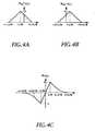
- Figs. 4A - 4Billustrate the autocorrelation outputs in terms of the received chip phase error.
- H(s)is a lowpass expression of a transfer function H(s) of the bandpass filter, and is a process of a PN sequence.
- the output of the square-law detectorcan be expressed as follows using R PN ⁇ (x) which is a function obtained by shifting the autocorrelation function of PN by a time period of +x.
- R PN ⁇ (x)which is a function obtained by shifting the autocorrelation function of PN by a time period of +x.
- H/(p) ⁇ (t)expresses an output response of the BPF to x(t).
- the bandwidth BLis sufficiently smaller than the chip rate
- the effect of the auto-noise caused by the PN sequence on the loopis negligible in the first-order approximation.
- the input to the loop filtercan be expressed by the following equation.
- a normalized delay estimate of the output of the spreading code replica generatoris expressed by the following equation using e(t).
- the average of squared tracking jitter due to noise componentis expressed as follows: where B L is an equivalent noise bandwidth of the LPF, and N e ( ⁇ t ) is expressed as where f( ⁇ t ) represents a square-law detection curve.
- an object of the present inventionis to provide a low power-consumption CDMA synchronizing circuit capable of high speed synchronization.
- Another object of the present inventionis to provide a correlation detector that can perform high accuracy tracking capable of eliminating the square loss resulting from the emphasis of the noise component by the square-law detector, which differs from the conventional code tracking circuit.
- a synchronising apparatusfor establishing synchronisation between a received signal and a despreading code by using a correlation between the received signal and the despreading code, the received signal being CDMA spread and the despreading code being used for despreading the received signal
- said synchronising apparatuscomprising a correlation detector including: spreading code replica generating means for generating a phase advanced replica of a CDMA spreading code with an advance phase with respect to said received signal, and phase retarded replica of the CDMA spreading code with a retarded phase with respect to said received signal; first multiplying means for multiplying said received signal by said phase advanced replica of the CDMA spreading code; a second multiplying means for multiplying said received signal by said phase retarded replica of the CDMA spreading code; first square-law detecting means for detecting a first correlation detection signal indicating a correlation between said phase advance replica of the CDMA spreading code and said received signal based on an output signal from said first multiplier; second square-law detecting means for
- a CDMA communication apparatuscomprising: an orthogonal detector for orthogonally detecting a CDMA spread received signal based on two detected signals whose phases are orthogonal to each other; two A/D converters for converting the two detected signals into digital signals, respectively; and synchronising apparatus in accordance with the first aspect, wherein: said switching circuit means comprises two switching circuits for inputting the two digital signals, respectively; said initial acquisition circuit means comprises two initial acquisition circuits for inputting respective outputs of said two switching circuits and taking a correlation between the output and a reference spreading code so as to output a correlation value; said acquisition decision circuit means comprises acquisition decision circuits respectively connected to said two initial acquisition circuits, for judging completion of synchronisation based on the correlation value and for outputting the judgement result to said switching circuit; and wherein said correlation detector is operable to input the other output of each of said two switching circuits and to take a correlation between the output and a reference spreading code generated in a spreading code replica generator incorporated therein; said two
- a synchronising methodfor establishing synchronisation between a received signal and a despreading code by using a correlation between the received signal and the despreading code, the received signal being CDMA spread and the despreading code being used for despreading the received signal
- said synchronising methodbeing characterised by comprising the steps of: taking a correlation between the received signal and a reference spreading code so as to perform initial acquisition; and taking a correlation between the received signal and the reference spreading code for tracking after completion of the synchronisation; said tracking step including the steps of: generating a phase advanced replica of a CDMA spreading code with an advance phase and a phase retarded replica of the CDMA spreading code with a retarded phase with respect to said received signal; firstly multiplying said received signal by said phase advanced replica of the CDMA spreading code; secondly multiplying said received signal by said phase retarded replica of the CDMA spreading code; detecting a first correlation detection signal indicating a correlation between said phase advanced replica of the CD
- Fig. 5shows an embodiment of the present invention.
- a received signal 21 applied to the input terminal 10is selectively supplied through a switching circuit 42 to an initial acquisition circuit 43 consisting of a matched filter or to a correlation detector 44.
- the initial acquisition circuit 43has an arrangement similar to that of Fig. 1.
- the correlation detector 44has a function similar to the correlation detectors of Figs. 2 and 3.
- the received signalis supplied to the initial acquisition circuit (matched filter) 43 in accordance with a switching signal 46 from an acquisition decision circuit 45, so that the correlation detection is performed.
- the correlation value detected by the matched filter 43is compared with a threshold value in the acquisition decision circuit 45.
- the acquisition decision circuit 45decides that the initial acquisition has been completed, and changes the switching circuit 42 using the switching signal 46.
- the received signalis inputted to multipliers 47 and 48 in the correlation detector 44.
- the acquisition decision circuit 45provides an initial reset signal 49 to a VCCG 29 and a spreading code replica generator 30.
- the received signal 21 after the initial acquisitionis multiplied by spreading codes 51 and 52 by the multipliers 47 and 48, the spreading codes being generated by the spreading code replica generator 30, and having phases shifted forward and backward in time by an amount T (less than one chip interval).
- the two productsare passed through bandpass filters (BPF) 53 and 54, and are square-law detected by square-law detectors 55 and 56, in which correlation values are detected.
- the correlation valuesare summed in the opposite phase by an adder 57.
- the sumis passed through a loop filter 58, and becomes a control voltage of the VCCG 29.
- the clock signal generated by the VCCG 29regulates the phase of the spreading code replica generator 30, tracks the synchronous point, and maintains the synchronization.
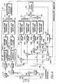
- Fig. 6illustrates an example, in which the spreading code replica generator 30I is synchronized with the outputs of the quadrature detector 62 which detects the received signal 21 applied to the input terminal 10.
- portions corresponding to those of Fig. 5are designated by the same reference numerals.
- Suffixes I and Qare attached to the same numerals as in Fig. 5 to represent processing circuits of the two detected outputs I and Q of the quadrature detector 62.
- the detected outputs I and Qare passed through lowpass filters 63 and 64, converted into digital signals by A/D converters 65 and 66, and supplied to switching circuits 42I and 42Q.
- the outputs of the initial acquisition circuits 43I and 43Qare square-law detected by square-law detectors 71 and 72, summed by an adder 73, and supplied to the acquisition decision circuit 45 which decides whether the initial acquisition is established or not.
- a spreading code replica generator 30I in the correlation detector 44generates an advanced spreading code 51I with an advanced phase and a retarded spreading code 52I with a retarded phase.
- a spreading code replica generator 30Qgenerates an advanced spreading code 51Q with the advanced phase and a retarded spreading code 52Q with the retarded phase.
- the detected output component I outputted from the switching circuit 42Iis multiplied by the advanced spreading code 51I and the retarded spreading code 52I by multipliers 47I and 48I.
- the detected output component Q outputted from the switching circuit 42Qis multiplied by the advanced spreading code 51Q and the retarded spreading code 52Q by multipliers 47Q and 48Q.
- the detected correlation values with the advanced spreading codes 51I and 51Qwhich are outputted from the multipliers 47I and 47Q, are passed through bandpass filters (BPFs) 53I and 53Q, square-law detected by square-law detectors 55I and 55Q, and are summed by an adder 67.
- the detected correlation values with the retarded spreading codes 52I and 52Qwhich are outputted from the multipliers 48I and 48Q, are passed through bandpass filters (BPFs) 54I and 54Q, square-law detected by square-law detectors 56I and 56Q, and are summed by an adder 68.
- the outputs of the adders 67 and 68are summed in the opposite phase by the adder 57.
- the synchronization processis separated into an initial acquisition process, and a tracking process using the correlation detector.
- the input PN sequenceis acquired so that the phase difference between the input PN sequence and the reference PN sequence is settled within a range sufficiently smaller than ⁇ one chip interval during the initial acquisition because the autocorrelation of the PN sequence is established only within a range of ⁇ one chip.
- the tracking processingholds the phase difference between the input PN sequence and the reference PN sequence within the range.
- the correlation detection during the acquisition phase which requires a high speed synchronizationis carried out in the initial acquisition circuit using a matched filter, and the correlation detection during the tracking phase which requires power saving rather than high speed synchronization is performed by the sliding correlation detector. This makes it possible to achieve the high speed acquisition, and power saving during the tracking because the power consumption of the initial acquisition circuit during the tracking is negligible.
- the tracking loop of the received chip phaseeliminates the primary modulated signal components which are included in the phase error signal of the replica signals, components only depending on the crosscorrelation can be extracted. This makes high accuracy tracking possible.
Landscapes
- Engineering & Computer Science (AREA)
- Computer Networks & Wireless Communication (AREA)
- Signal Processing (AREA)
- Synchronisation In Digital Transmission Systems (AREA)
- Mobile Radio Communication Systems (AREA)
- Cable Transmission Systems, Equalization Of Radio And Reduction Of Echo (AREA)
Description
- The present invention relates to a correlationdetector of a radio receiver in a CDMA (Code DivisionMultiple Access) system which carries out multipleaccess by using a spread spectrum in mobilecommunications.
- In particular, the present invention relates to aCDMA synchronizing circuit that synchronizes aspreading code for despreading the received signal to aspreading code in a received signal in CDMAcommunications.
- CDMA communications perform multiple accesspropagation by spreading information into widebandsignals using spreading codes with rates higher thanthe rate of the information, and are roughly dividedinto direct sequence (DS) systems that spread modulatedsignals by high rate spreading codes, and frequencyhopping (FH) systems. The FH system resolves eachsymbol into smaller elements called chips, andtranslates the chips into signals with different centerfrequency at a high speed. Since the implementation ofthe FH system is difficult, the DS system is generallyused. The DS system recovers the original narrowbandsignal by despreading the wideband received inputsignal at a receiving end, followed by demodulation.In the despreading process, correlation detection is performed between the spreading code included in thereceived signal and a spreading code generated at thereceiving end.
- Thus, the receiver for receiving the spread signalin the DS system is usually provided with a replica(reference PN sequence) of the PN sequence (received PNsequence) in the received signal, and establishessynchronization between the reference PN sequence andthe received PN sequence. Fig. 1 shows a conventionalsynchronization circuit using a matched filter. Thereceived signal applied to an
input terminal 10 issupplied to amemory circuit 11 with taps. The numberof taps of the tappedmemory circuit 11 is the same asthe number of chips in a spreading code interval (thatis, a processing gain PG). The outputs of the taps ofthememory circuit 11 are multiplied by the referencespreading code stored in atap coefficient circuit 13bymultipliers 12. The resultant products are summedby anintegrator 14, which outputs the sum from itsoutput terminal 16 as acorrelation value 15. - Using the matched filter makes it possible toquickly establish the synchronization because the peaksof the correlation value appear at the same interval asthat of the spreading code. However, since thecapacity of the tapped
memory circuit 11 and the numberof themultipliers 12 increase in proportion to theprocessing gain, the power consumption of the receiverwill increase with the interval of the spreading code.Therefore, the conventional synchronizing circuit isnot appropriate for portable devices or mobile devices. - Using a sliding correlation detector as shown inFig. 2 makes possible power saving and downsizing ofthe circuit. In Fig. 2, a received
signal 21 inputtedto theinput terminal 10 is multiplied by a spreading code, which is generated by a spreadingcode replicagenerator 30, by amultiplier 22 to obtain thecorrelation between the two. The resultant product ispassed through a bandpass filter (BPF) 23, followed bypeak power detection by a square-law detector 24. Thedetected power is integrated over a fixed time(normally, ± one chip interval) by an integral-dumpcircuit 25. The integrated result is compared with athreshold value by a threshold value decision circuit26 which decides that initial acquisition has beencompleted if the integrated result exceeds thethreshold value, and proceeds to the next step(tracking mode). If the integrated result is less thanthe threshold value, the decision circuit 26 supplies acontrol voltage 28 to a voltage controlled clockgenerator (VCCG) 29 which slides the phase of thereplica so that the phase of the spreading codegenerated by the spreadingcode replica generator 30 isshifted by 1/N chip interval (N is a natural numberequal to or greater than one). The initial acquisitionhas been completed by repeating the processing untilthe synchronized point is found. - According to this method, it is necessary tointegrate the spreading replica over the fixed timeevery time the replica is shifted by 1/N chip interval,and to detect the synchronized point in the interval ofthe spreading code by comparing the integrated result.This will lengthen the acquisition time, and hence, itis not appropriate for a system which requires a quickacquisition.
- In addition, the conventional correlation detectorpresents another problem in that it provides a ratherlarge error in maintaining (tracking) thesynchronization.
- Fig. 3 is a block diagram showing a conventionalDLL (Delay Locked Loop)
correlation detector 44. InFig. 3, the same functional blocks are designated bythe same numerals as in Fig. 2. Thereference numeral 10 designates a spreaded signal input terminal, 102designates a decided data output terminal, 111 denotesa multiplier, and 510 designates a delay circuit. Thecorrelation detector 44 calculates correlations betweenthe input modulated signal and code sequences formed byadvancing and retarding the chip phase of the replicaby 1/N, respectively. The correlated signals arepassed through bandpass filters (BPFs) 53 and 54 whicheliminate unnecessary high frequency components, andare detected by square-law detectors adder 57in the opposite phase, so that an error signal voltageis obtained which indicates an amount of a phasedifference. The error signal voltage is passed throughaloop filter 58, and is fed back to aVCCG 29 tocorrect the phase of the replica code sequence. Thephase advance (or retardation) time δ ranges from 0 toTc, where Tc is the chip interval. - Applying the CDMA system to cellularcommunications requires high accuracy transmissionpower control that keeps constant base station'sreceived levels of signals sent from all the mobilestations. The CDMA system can increase the capacity interms of the number of subscribers per frequency bandas compared with the FDMA system or the TDMA system.This is because conventional systems which employfrequency orthogonality cannot utilize the same carrierfrequencies in the contiguous cells, and even spacediversity systems cannot reuse the same frequencieswithin four cells.
- In contrast with this, the CDMA system makes itpossible to reuse the same carrier frequency in thecontiguous cells because the signals of the othercommunicators are regarded as white noise.Accordingly, the CDMA system can increase the capacityin terms of the number of subscribers as compared withthe FDMA system or the TDMA system. If the processinggain is pg, the number of spreading code sequences thatcompletely orthogonalize with each other is pg. Thisnumber of the code sequences, however, will beinsufficient when information data is spread by usingonly code sequences of one symbol interval long. Toovercome this problem, the number of the spreadingcodes is increased almost infinitely by superimposinglong code sequences of a very long interval over shortcode sequences of one symbol interval.
- Unlike M sequences that have definiteautocorrelation characteristics, the autocorrelation ofGold sequences and that of the.sequences obtained bysuperimposing very long code sequences over the Goldsequences will have undesired peaks of considerableamplitudes in addition to the normal correlation peakin one symbol interval. As a result, when the receivedsignal level is low, a lock may be lost in theconventional delay-locked loop using one chip intervallock. Let us formulate the operation principle of thedelay-locked loop of Fig. 3. First, the input signalis expressed by the following equation.where S is average signal power, c(t-τt) is a receivedspreading code including a propagation delay, m(t-τt)represents data modulation including the propagationdelay, ω0 is the angular frequency of a carrier, and(t) = 0 + Ω0t is an unknown carrier phase which isrepresented as the sum of a constant term and a termproportional to the Doppler frequency. The powerspectrum density of n(t) is N0/2. δω0 is an angularfrequency error between the center frequency of amodulation signal and a local oscillation frequency.In addition, the bandpassed expression of input thermalnoise ni(t) is given by
 where Nc(t) and Ns(t) are assumed to be approximatelyand statistically independent and steady. Thespreading replica sequence of the advanced phase andthat of the retarded phase can be expressed as follows:
 where τ andt is a propagation delay estimated by the DLL atthe receiving side. The crosscorrelation output of thephase detector is expressed as
 where Km is the gain of the phase detector which isassumed to be equal in both branches, and
× representsthe average of a set. - Figs. 4A - 4B illustrate the autocorrelationoutputs in terms of the received chip phase error.Here,is a normalized propagation delay error. H(s) is alowpass expression of a transfer function H(s) of thebandpass filter, and
 is a process of a PN sequence.
- The output of the square-law detector can beexpressed as follows using RPN±(x) which is a functionobtained by shifting the autocorrelation function of PNby a time period of +x.where
 Here, H/(p)×(t) expresses an output response of the BPFto x(t). If the bandwidth BL is sufficiently smallerthan the chip rate, the effect of the auto-noise causedby the PN sequence on the loop is negligible in thefirst-order approximation. Neglecting the auto-noiseand the secondary harmonic caused by the square-law detection, the input to the loop filter can beexpressed by the following equation.
 where
where According to the foregoing, a normalized delay estimateof the output of the spreading code replica generatoris expressed by the following equation using e(t).
 Thus, estimated error εt is expressed as

- Resolving the first term in the blanket of theabove equation into an average value term and modulatedauto-noise term giveswhere < > expresses an average in time, and
 where Sm(f) is a power spectrum density of the data modulation. The M2 term is the integral of the datamodulation power spectrum density over the passband ofthe filter, and indicates the data modulation power inthe passband. Since the bandwidth of the loop is muchsmaller than the data symbol rate, the auto-noiseassociated with the second term of equation (11) isnegligible.
- From equation (10), the following equation isobtained.where a dot placed over characters represents a timedifferential, and η is given by

- Briefly, the average of squared tracking jitterdue to noise component is expressed as follows:where BL is an equivalent noise bandwidth of the LPF, and Ne(εt) is expressed as
 where f(εt) represents a square-law detection curve.
- Since the conventional DLL uses the square-lawdetector as shown in equation (15), the noise componentis also squared. This will increase the trackingjitter as shown in equation (14).
- Therefore, an object of the present invention isto provide a low power-consumption CDMA synchronizingcircuit capable of high speed synchronization. Anotherobject of the present invention is to provide acorrelation detector that can perform high accuracytracking capable of eliminating the square lossresulting from the emphasis of the noise component bythe square-law detector, which differs from theconventional code tracking circuit.
- In a first aspect of the present invention, thereis provided a synchronising apparatus for establishingsynchronisation between a received signal and adespreading code by using a correlation between thereceived signal and the despreading code, the receivedsignal being CDMA spread and the despreading code beingused for despreading the received signal, saidsynchronising apparatus comprising a correlation detectorincluding: spreading code replica generating means forgenerating a phase advanced replica of a CDMA spreadingcode with an advance phase with respect to said receivedsignal, and phase retarded replica of the CDMA spreadingcode with a retarded phase with respect to said receivedsignal; first multiplying means for multiplying saidreceived signal by said phase advanced replica of theCDMA spreading code; a second multiplying means formultiplying said received signal by said phase retardedreplica of the CDMA spreading code; first square-lawdetecting means for detecting a first correlationdetection signal indicating a correlation between saidphase advance replica of the CDMA spreading code and saidreceived signal based on an output signal from said firstmultiplier; second square-law detecting means fordetecting a second correlation detection signalindicating a correlation between said phase retarded replica of the CDMA spreading code and said receivedsignal based on an output signal from said secondmultiplier; adding means for summing said first andsecond correlation detection signals in opposite phase;and clock generating circuit means for generating a clocksignal whose phase is controlled by an output from saidadding means to control said spreading code replicagenerating means, the synchronising apparatus beingcharacterised in that it further comprises: a switchingcircuit means operable to receive the received signal;an initial acquisition circuit means for receiving anoutput of said switching circuit means and for taking acorrelation between said output and a reference spreadingcode so as to output a correlation value; an acquisitiondecision circuit means connected to said initialacquisition circuit means, for judging completion ofsynchronisation based on the correlation value and foroutputting the judgement result to said switching circuitmeans; and wherein said correlation detector is operableto receive another output of said switching circuit meansand to take a correlation between said other output anda reference spreading code generated in a spreading codereplica generator incorporated therein; said switchingcircuit means being operable to output a received signalto said initial acquisition circuit means at the time of asynchronism based on the output of said acquisitiondecision circuit means while outputting a received signalto said correlation detector after the completion ofsynchronisation.
- In a second aspect of the present invention, thereis provided a CDMA communication apparatus comprising:an orthogonal detector for orthogonally detecting a CDMAspread received signal based on two detected signalswhose phases are orthogonal to each other; two A/Dconverters for converting the two detected signals intodigital signals, respectively; and synchronisingapparatus in accordance with the first aspect, wherein:said switching circuit means comprises two switchingcircuits for inputting the two digital signals,respectively; said initial acquisition circuit meanscomprises two initial acquisition circuits for inputtingrespective outputs of said two switching circuits andtaking a correlation between the output and a referencespreading code so as to output a correlation value; saidacquisition decision circuit means comprises acquisitiondecision circuits respectively connected to said twoinitial acquisition circuits, for judging completion ofsynchronisation based on the correlation value and foroutputting the judgement result to said switchingcircuit; and wherein said correlation detector is operable to input the other output of each of said twoswitching circuits and to take a correlation between theoutput and a reference spreading code generated in aspreading code replica generator incorporated therein;said two switching circuits being operable to output areceived signal to said initial acquisition circuit atthe time of asynchronism while outputting a receivedsignal to said correlation detector after the completionof synchronisation based on the output of saidacquisition decision circuit; and wherein, in saidcorrelation detector, said spreading code generatingmeans comprises two spreading code replica generators forrespectively generating a phase advanced replica of aCDMA spreading code with an advance phase and a phaseretarded replica of the CDMA spreading code with aretarded phase with respect to said two digital signals;said first multiplying means comprises two firstmultipliers for respectively multiplying said two digitalsignals by said phase retarded replica of the CDMAspreading code; said second multiplying means comprisestwo second multipliers for respectively multiplying saidtwo digital signals by said phase retarded replica of theCDMA spreading code; said first square-law detectingmeans comprises two first square-law detectors fordetecting first correlation detection signals indicating correlations between said phase advanced replica of theCDMA spreading code and said two digital signals basedon output signals from said first multipliers; saidsecond square-law detecting means comprises two secondsquare-law detectors for detecting second correlationdetection signals indicating correlations between saidphase retarded replica of the CDMA spreading code andsaid two digital signals based on output signals fromsaid second multipliers; said adding means comprises twofirst adders for summing said corresponding first andsecond correlation detection signals, and a second adderfor summing the outputs of said first adders in oppositephase; and said clock generating circuit means isoperable to generate a clock signal whose phase iscontrolled by an output from a third adder to controlsaid spreading code replica generator.
- In a third aspect of the present invention, thereis provided a synchronising method for establishingsynchronisation between a received signal and adespreading code by using a correlation between thereceived signal and the despreading code, the receivedsignal being CDMA spread and the despreading code beingused for despreading the received signal, saidsynchronising method being characterised by comprisingthe steps of: taking a correlation between the received signal and a reference spreading code so as to performinitial acquisition; and taking a correlation between thereceived signal and the reference spreading code fortracking after completion of the synchronisation; saidtracking step including the steps of: generating a phaseadvanced replica of a CDMA spreading code with an advancephase and a phase retarded replica of the CDMA spreadingcode with a retarded phase with respect to said receivedsignal; firstly multiplying said received signal by saidphase advanced replica of the CDMA spreading code;secondly multiplying said received signal by said phaseretarded replica of the CDMA spreading code; detectinga first correlation detection signal indicating acorrelation between said phase advanced replica of theCDMA spreading code and said received signal based on anoutput at said first multiplying step by square-lawdetection; detecting a second correlation detectionsignal indicating a correlation between said phaseretarded replica of the CDMA spreading code and saidreceived signal based on an output at said secondmultiplying step by square-law detection; summing saidfirst and second correlation detection signals inopposite phase; and controlling a phase of a replica codeto be output based on the output at said summing step.
- Fig. 1 is a block diagram showing a synchronizingcircuit or an initial acquisition circuit of aconventional matched filter;
- Fig. 2 is a block diagram showing a conventionalsliding correlator;
- Fig, 3 is a block diagram showing a conventionalDLL.
- Figs. 4A-4C are diagrams illustratingcrosscorrelation output signals in terms of a phaseerror of received signal;
- Fig. 5 is a block diagram showing a basicarrangement of a first embodiment of a correlationdetector in accordance with the present invention; and
- Fig. 6 is a block diagram showing another basicarrangement of the first embodiment of a correlationdetector in accordance with the present invention.
- The best mode for carrying out the invention willnow be described with reference to the accompanyingdrawings.
- Fig. 5 shows an embodiment of the presentinvention. A received
signal 21 applied to theinput terminal 10 is selectively supplied through a switchingcircuit 42 to aninitial acquisition circuit 43consisting of a matched filter or to acorrelationdetector 44. Theinitial acquisition circuit 43 has anarrangement similar to that of Fig. 1. Thecorrelationdetector 44 has a function similar to the correlationdetectors of Figs. 2 and 3. When the initialacquisition has not yet been completed, the receivedsignal is supplied to the initial acquisition circuit(matched filter) 43 in accordance with a switchingsignal 46 from anacquisition decision circuit 45, sothat the correlation detection is performed. Thecorrelation value detected by the matchedfilter 43 iscompared with a threshold value in theacquisitiondecision circuit 45. If the correlation value isgreater than or equal to the threshold value, theacquisition decision circuit 45 decides that theinitial acquisition has been completed, and changes theswitchingcircuit 42 using theswitching signal 46.Thus, the received signal is inputted tomultipliers correlation detector 44. Theacquisitiondecision circuit 45 provides aninitial reset signal 49to aVCCG 29 and a spreadingcode replica generator 30. - The received
signal 21 after the initialacquisition is multiplied by spreading codes 51 and 52by themultipliers code replica generator 30,and having phases shifted forward and backward in timeby an amount T (less than one chip interval). The twoproducts are passed through bandpass filters (BPF) 53and 54, and are square-law detected by square-lawdetectors adder 57. The sum is passed through aloop filter 58, and becomes a control voltageof theVCCG 29. The clock signal generated by theVCCG 29 regulates the phase of the spreadingcode replicagenerator 30, tracks the synchronous point, andmaintains the synchronization. - Fig. 6 illustrates an example, in which thespreading code replica generator 30I is synchronizedwith the outputs of the
quadrature detector 62 whichdetects the receivedsignal 21 applied to theinputterminal 10. In this figure, portions corresponding tothose of Fig. 5 are designated by the same referencenumerals. Suffixes I and Q are attached to the samenumerals as in Fig. 5 to represent processing circuitsof the two detected outputs I and Q of thequadraturedetector 62. The detected outputs I and Q are passedthroughlowpass filters D converters law detectors adder 73, and supplied to theacquisition decision circuit 45 which decides whetherthe initial acquisition is established or not. - A spreading code replica generator 30I in the
correlation detector 44 generates an advanced spreadingcode 51I with an advanced phase and a retardedspreading code 52I with a retarded phase. Likewise, aspreading code replica generator 30Q generates anadvanced spreading code 51Q with the advanced phase anda retarded spreading code 52Q with the retarded phase.The detected output component I outputted from theswitching circuit 42I is multiplied by the advancedspreading code 51I and the retarded spreading code 52Iby multipliers 47I and 48I. Likewise, the detected output component Q outputted from the switching circuit42Q is multiplied by the advanced spreading code 51Qand the retarded spreading code 52Q by multipliers 47Qand 48Q. - The detected correlation values with the advancedspreading codes 51I and 51Q, which are outputted fromthe multipliers 47I and 47Q, are passed throughbandpass filters (BPFs) 53I and 53Q, square-lawdetected by square-law detectors 55I and 55Q, and aresummed by an
adder 67. Similarly, the detectedcorrelation values with the retarded spreading codes52I and 52Q, which are outputted from the multipliers48I and 48Q, are passed through bandpass filters (BPFs)54I and 54Q, square-law detected by square-lawdetectors 56I and 56Q, and are summed by anadder 68.The outputs of theadders adder 57. These operations aresimilar to those of Fig. 5. - According to the first embodiment, thesynchronization process is separated into an initialacquisition process, and a tracking process using thecorrelation detector. The input PN sequence isacquired so that the phase difference between the inputPN sequence and the reference PN sequence is settledwithin a range sufficiently smaller than ± one chipinterval during the initial acquisition because theautocorrelation of the PN sequence is established onlywithin a range of ± one chip. The tracking processingholds the phase difference between the input PNsequence and the reference PN sequence within therange.
- As described above in detail, according to thepresent invention, the correlation detection during theacquisition phase which requires a high speedsynchronization is carried out in the initialacquisition circuit using a matched filter, and thecorrelation detection during the tracking phase whichrequires power saving rather than high speedsynchronization is performed by the sliding correlationdetector. This makes it possible to achieve the highspeed acquisition, and power saving during the trackingbecause the power consumption of the initialacquisition circuit during the tracking is negligible.
- In addition, according to the present invention,since the tracking loop of the received chip phaseeliminates the primary modulated signal componentswhich are included in the phase error signal of thereplica signals, components only depending on thecrosscorrelation can be extracted. This makes high accuracy tracking possible.


Claims (3)
- A synchronising apparatus for establishingsynchronisation between a received signal and adespreading code by using a correlation between thereceived signal and the despreading code, the receivedsignal being CDMA spread and the despreading code beingused for despreading the received signal, saidsynchronising apparatus comprising a correlation detector(44) including:spreading code replica generating means (30) forgenerating a phase advanced replica of a CDMA spreadingcode with an advance phase with respect to said receivedsignal, and phase retarded replica of the CDMA spreadingcode with a retarded phase with respect to said receivedsignal;first multiplying means (47) for multiplying saidreceived signal by said phase advanced replica of theCDMA spreading code;a second multiplying means (48) for multiplying saidreceived signal by said phase retarded replica of theCDMA spreading code;first square-law detecting means (55) for detectinga first correlation detection signal indicating acorrelation between said phase advance replica of the CDMA spreading code and said received signal based on anoutput signal from said first multiplier (47);second square-law detecting means (56) for detectinga second correlation detection signal indicating acorrelation between said phase retarded replica of theCDMA spreading code and said received signal based on anoutput signal from said second multiplier (48);adding means (57) for summing said first and secondcorrelation detection signals in opposite phase; andclock generating circuit means (58, 29) forgenerating a clock signal whose phase is controlled by anoutput from said adding means to control said spreadingcode replica generating means, the synchronisingapparatus beingcharacterised in that it furthercomprises:a switching circuit means (42) operable to receivethe received signal;an initial acquisition circuit means (43) forreceiving an output of said switching circuit means andfor taking a correlation between said output and areference spreading code so as to output a correlationvalue;an acquisition decision circuit means (45) connectedto said initial acquisition circuit means, for judgingcompletion of synchronisation based on the correlation value and for outputting the judgement result to saidswitching circuit means; and whereinsaid correlation detector (44) is operable toreceive another output of said switching circuit meansand to take a correlation between said other output anda reference spreading code generated in a spreading codereplica generator incorporated therein;said switching circuit means (42) being operable tooutput a received signal to said initial acquisitioncircuit means (43) at the time of asynchronism based onthe output of said acquisition decision circuit means(45) while outputting a received signal to saidcorrelation detector (44) after the completion ofsynchronisation.
- A CDMA communication apparatus comprising:an orthogonal detector (62) for orthogonallydetecting a CDMA spread received signal based on twodetected signals (I, Q) whose phases are orthogonal toeach other;two A/D converters (65, 66) for converting the twodetected signals into digital signals, respectively; andsynchronising apparatus in accordance with claim 1,wherein:said switching circuit means comprises two switching circuits (42I, 42Q) for inputting the two digitalsignals, respectively;said initial acquisition circuit means comprises twoinitial acquisition circuits (43I, 43Q) for inputtingrespective outputs of said two switching circuits andtaking a correlation between the output and a referencespreading code so as to output a correlation value;said acquisition decision circuit means comprisesacquisition decision circuits (45) respectively connectedto said two initial acquisition circuits, for judgingcompletion of synchronisation based on the correlationvalue and for outputting the judgement result to saidswitching circuit; and whereinsaid correlation detector (44) is operable to inputthe other output of each of said two switching circuitsand to take a correlation between the output and areference spreading code generated in a spreading codereplica generator incorporated therein;said two switching circuits (42) being operable tooutput a received signal to said initial acquisitioncircuit (43) at the time of asynchronism while outputtinga received signal to said correlation detector (44) afterthe completion of synchronisation based on the output ofsaid acquisition decision circuit; andwherein, in said correlation detector (44),said spreading code generating means comprises twospreading code replica generators (30I, 30Q) forrespectively generating a phase advanced replica of aCDMA spreading code with an advance phase and a phaseretarded replica of the CDMA spreading code with aretarded phase with respect to said two digital signals;said first multiplying means comprises two firstmultipliers (47I, 47Q) for respectively multiplying saidtwo digital signals by said phase retarded replica of theCDMA spreading code;said second multiplying means comprises two secondmultipliers (48I, 48Q) for respectively multiplying saidtwo digital signals by said phase retarded replica of theCDMA spreading code;said first square-law detecting means comprises twofirst square-law detectors (55I, 55Q) for detecting firstcorrelation detection signals indicating correlationsbetween said phase advanced replica of the CDMA spreadingcode and said two digital signals based on output signalsfrom said first multipliers;said second square-law detecting means comprises twosecond square-law detectors (56I, 56Q) for detectingsecond correlation detection signals indicatingcorrelations between said phase retarded replica of theCDMA spreading code and said two digital signals based on output signals from said second multipliers;said adding means comprises two first adders (67,68) for summing said corresponding first and secondcorrelation detection signals, and a second adder (57)for summing the outputs of said first adders in oppositephase; andsaid clock generating circuit means (58, 29) isoperable to generate a clock signal whose phase iscontrolled by an output from a third adder to controlsaid spreading code replica generator.
- A synchronising method for establishingsynchronisation between a received signal and adespreading code by using a correlation between thereceived signal and the despreading code, the receivedsignal being CDMA spread and the despreading code beingused for despreading the received signal, saidsynchronising method beingcharacterised by comprisingthe steps of:taking a correlation between the received signal anda reference spreading code so as to perform initialacquisition; andtaking a correlation between the received signal andthe reference spreading code for tracking aftercompletion of the synchronisation;said tracking step including the steps of:generating a phase advanced replica of a CDMAspreading code with an advance phase and a phase retardedreplica of the CDMA spreading code with a retarded phasewith respect to said received signal;firstly multiplying said received signal by saidphase advanced replica of the CDMA spreading code;secondly multiplying said received signal by saidphase retarded replica of the CDMA spreading code;detecting a first correlation detection signalindicating a correlation between said phase advancedreplica of the CDMA spreading code and said receivedsignal based on an output at said first multiplying stepby square-law detection;detecting a second correlation detection signalindicating a correlation between said phase retardedreplica of the CDMA spreading code and said receivedsignal based on an output at said second multiplying stepby square-law detection;summing said first and second correlation detectionsignals in opposite phase; andcontrolling a phase of a replica code to be outputbased on the output at said summing step.
Applications Claiming Priority (5)
| Application Number | Priority Date | Filing Date | Title |
|---|---|---|---|
| JP25712793 | 1993-10-14 | ||
| JP25712793 | 1993-10-14 | ||
| JP14205794 | 1994-06-23 | ||
| JP14205794 | 1994-06-23 | ||
| EP94929651AEP0682427B1 (en) | 1993-10-14 | 1994-10-13 | Correlation detector and communication apparatus |
Related Parent Applications (1)
| Application Number | Title | Priority Date | Filing Date |
|---|---|---|---|
| EP94929651ADivisionEP0682427B1 (en) | 1993-10-14 | 1994-10-13 | Correlation detector and communication apparatus |
Publications (3)
| Publication Number | Publication Date |
|---|---|
| EP1075089A2 EP1075089A2 (en) | 2001-02-07 |
| EP1075089A3 EP1075089A3 (en) | 2001-02-28 |
| EP1075089B1true EP1075089B1 (en) | 2003-01-02 |
Family
ID=26474191
Family Applications (2)
| Application Number | Title | Priority Date | Filing Date |
|---|---|---|---|
| EP00202794AExpired - LifetimeEP1075089B1 (en) | 1993-10-14 | 1994-10-13 | Correlation detector and communication apparatus |
| EP94929651AExpired - LifetimeEP0682427B1 (en) | 1993-10-14 | 1994-10-13 | Correlation detector and communication apparatus |
Family Applications After (1)
| Application Number | Title | Priority Date | Filing Date |
|---|---|---|---|
| EP94929651AExpired - LifetimeEP0682427B1 (en) | 1993-10-14 | 1994-10-13 | Correlation detector and communication apparatus |
Country Status (7)
| Country | Link |
|---|---|
| US (1) | US5638362A (en) |
| EP (2) | EP1075089B1 (en) |
| KR (1) | KR100205529B1 (en) |
| CN (1) | CN1129268C (en) |
| CA (1) | CA2151737C (en) |
| DE (2) | DE69429505T2 (en) |
| WO (1) | WO1995010903A1 (en) |
Families Citing this family (77)
| Publication number | Priority date | Publication date | Assignee | Title |
|---|---|---|---|---|
| US6448926B1 (en) | 1993-11-19 | 2002-09-10 | Itt Manufacturing Enterprises, Inc. | Multi-band, multi-function integrated transceiver |
| WO1996021294A1 (en)* | 1995-01-05 | 1996-07-11 | Ntt Mobile Communications Network Inc. | Device and method for coherent-tracking of cdma receiver |
| JP2715987B2 (en)* | 1995-05-23 | 1998-02-18 | 日本電気株式会社 | Synchronization acquisition device and synchronization acquisition method for spread spectrum communication system |
| US5627855A (en)* | 1995-05-25 | 1997-05-06 | Golden Bridge Technology, Inc. | Programmable two-part matched filter for spread spectrum |
| DE69632566T2 (en)* | 1995-06-13 | 2004-11-11 | Ntt Docomo, Inc. | METHOD AND DEVICE FOR SYNCHRONIZING A SPREAD CODE |
| US6816473B2 (en) | 1995-06-30 | 2004-11-09 | Interdigital Technology Corporation | Method for adaptive forward power control for spread-spectrum communications |
| US7929498B2 (en) | 1995-06-30 | 2011-04-19 | Interdigital Technology Corporation | Adaptive forward power control and adaptive reverse power control for spread-spectrum communications |
| US6697350B2 (en) | 1995-06-30 | 2004-02-24 | Interdigital Technology Corporation | Adaptive vector correlator for spread-spectrum communications |
| US6885652B1 (en) | 1995-06-30 | 2005-04-26 | Interdigital Technology Corporation | Code division multiple access (CDMA) communication system |
| ZA965340B (en) | 1995-06-30 | 1997-01-27 | Interdigital Tech Corp | Code division multiple access (cdma) communication system |
| US7020111B2 (en)* | 1996-06-27 | 2006-03-28 | Interdigital Technology Corporation | System for using rapid acquisition spreading codes for spread-spectrum communications |
| US7072380B2 (en) | 1995-06-30 | 2006-07-04 | Interdigital Technology Corporation | Apparatus for initial power control for spread-spectrum communications |
| US6801516B1 (en) | 1995-06-30 | 2004-10-05 | Interdigital Technology Corporation | Spread-spectrum system for assigning information signals having different data rates |
| US7123600B2 (en) | 1995-06-30 | 2006-10-17 | Interdigital Technology Corporation | Initial power control for spread-spectrum communications |
| US6788662B2 (en) | 1995-06-30 | 2004-09-07 | Interdigital Technology Corporation | Method for adaptive reverse power control for spread-spectrum communications |
| JP3390762B2 (en) | 1995-07-28 | 2003-03-31 | シャープ株式会社 | Matched filter circuit |
| JPH0946174A (en)* | 1995-07-31 | 1997-02-14 | Sharp Corp | Filter circuit |
| JP3269959B2 (en)* | 1996-01-16 | 2002-04-02 | 株式会社日立国際電気 | Correlation filter and CDMA receiver |
| JP2780697B2 (en)* | 1996-03-22 | 1998-07-30 | 日本電気株式会社 | Method and apparatus for acquiring synchronization in correlation demodulation |
| JPH09321667A (en)* | 1996-05-29 | 1997-12-12 | Yozan:Kk | Receiver for cdma communication system |
| JP2858561B2 (en)* | 1996-05-30 | 1999-02-17 | 日本電気株式会社 | Digital DLL circuit |
| US5987059A (en)* | 1996-07-12 | 1999-11-16 | General Electric Company | Method for Doppler-replica harmonic avoidance |
| EP1467221B1 (en)* | 1996-07-12 | 2015-12-09 | General Electric Company | GPS receiver with signal memories and parallel correlators |
| US5966403A (en)* | 1996-07-19 | 1999-10-12 | Trimble Navigation Limited | Code multipath error estimation using weighted correlations |
| US5838669A (en)* | 1996-08-28 | 1998-11-17 | At&T Corp. | Method of synchronizing satellite switched CDMA communication system |
| JP2923867B2 (en)* | 1996-10-28 | 1999-07-26 | 日本電気株式会社 | Transmission power control method |
| US5953327A (en)* | 1996-10-29 | 1999-09-14 | Stanford Telecommunications, Inc. | Class of low cross correlation non-palindromic synchronization sequences for code tracking in synchronous multiple access communication systems |
| JP3323760B2 (en)* | 1996-11-07 | 2002-09-09 | 株式会社日立製作所 | Spread spectrum communication system |
| JP2762996B1 (en)* | 1996-12-11 | 1998-06-11 | 日本電気株式会社 | Receiver |
| US5974042A (en)* | 1997-02-28 | 1999-10-26 | Motorola, Inc. | Service detection circuit and method |
| US5999561A (en)* | 1997-05-20 | 1999-12-07 | Sanconix, Inc. | Direct sequence spread spectrum method, computer-based product, apparatus and system tolerant to frequency reference offset |
| US6741638B2 (en) | 1997-06-23 | 2004-05-25 | Schlumbergersema Inc. | Bandpass processing of a spread spectrum signal |
| US6456644B1 (en)* | 1997-06-23 | 2002-09-24 | Cellnet Data Systems, Inc. | Bandpass correlation of a spread spectrum signal |
| US6628699B2 (en) | 1997-06-23 | 2003-09-30 | Schlumberger Resource Management Systems, Inc. | Receiving a spread spectrum signal |
| US6047016A (en)* | 1997-06-23 | 2000-04-04 | Cellnet Data Systems, Inc. | Processing a spread spectrum signal in a frequency adjustable system |
| US6263009B1 (en) | 1997-06-23 | 2001-07-17 | Cellnet Data Systems, Inc. | Acquiring a spread spectrum signal |
| US6178197B1 (en) | 1997-06-23 | 2001-01-23 | Cellnet Data Systems, Inc. | Frequency discrimination in a spread spectrum signal processing system |
| KR100268361B1 (en)* | 1997-07-01 | 2000-10-16 | 정규석 | Initial Synchronization Method for Code Division Multiple Access Fixed Receiver System |
| EP0899893A1 (en)* | 1997-09-01 | 1999-03-03 | Kabushiki Kaisha Toshiba | Spread spectrum communications receiver |
| US6208632B1 (en) | 1998-01-29 | 2001-03-27 | Sharp Laboratories Of America | System and method for CDMA channel estimation |
| US6085104A (en)* | 1998-03-25 | 2000-07-04 | Sharp Laboratories Of America, Inc. | Pilot aided, time-varying finite impulse response, adaptive channel matching receiving system and method |
| US6115370A (en) | 1998-05-26 | 2000-09-05 | Nera Wireless Broadband Access As | Method and system for protocols for providing voice, data, and multimedia services in a wireless local loop system |
| US6131012A (en) | 1998-05-26 | 2000-10-10 | Nera Wireless Broadband Access As | Method and system for a micro-channel bank for providing voice, data, and multimedia services in a wireless local loop system |
| US6144645A (en)* | 1998-05-26 | 2000-11-07 | Nera Wireless Broadband Access As | Method and system for an air interface for providing voice, data, and multimedia services in a wireless local loop system |
| US6229857B1 (en)* | 1998-06-02 | 2001-05-08 | Intel Corporation | Adaptive ingress filtering system |
| CN1065997C (en)* | 1998-07-17 | 2001-05-16 | 中国人民解放军信息工程学院 | Two stage mixed direct series spread spectrum/code devision multiple access communication fast capturing structure |
| JP3377451B2 (en)* | 1998-08-26 | 2003-02-17 | シャープ株式会社 | Matched filter |
| JP3092598B2 (en)* | 1998-09-08 | 2000-09-25 | 日本電気株式会社 | Mobile communication device and mobile communication method |
| US6205168B1 (en) | 1998-11-12 | 2001-03-20 | Sharp Laboratories Of America, Inc. | Sequential detection system and method with adaptive bias |
| JP3323453B2 (en) | 1999-02-09 | 2002-09-09 | 松下電器産業株式会社 | CDMA receiving apparatus and CDMA receiving method |
| US7443906B1 (en)* | 1999-05-31 | 2008-10-28 | Electronics And Telecommunications Research Institute | Apparatus and method for modulating data message by employing orthogonal variable spreading factor (OVSF) codes in mobile communication system |
| KR20010003093A (en)* | 1999-06-21 | 2001-01-15 | 김영환 | TBS and CE debugging method of CDMA system |
| US6735242B1 (en)* | 1999-08-30 | 2004-05-11 | Nokia Corporation | Time tracking loop for pilot aided direct sequence spread spectrum systems |
| JP3279547B2 (en)* | 1999-09-20 | 2002-04-30 | 日本電気株式会社 | Synchronous acquisition device for CDMA receiver |
| FI114887B (en)* | 1999-10-13 | 2005-01-14 | U Nav Microelectronics Corp | Signal detection system of a spread spectrum receiver |
| US6421372B1 (en) | 1999-11-10 | 2002-07-16 | Itt Manufacturing Enterprises, Inc. | Sequential-acquisition, multi-band, multi-channel, matched filter |
| US6434129B1 (en) | 1999-12-01 | 2002-08-13 | Nera Wireless Broadband Access As | Method and system for an air interface for providing voice, data, and multimedia services in a wireless local loop system |
| JP2001177436A (en)* | 1999-12-15 | 2001-06-29 | Nec Corp | Afc controller in mobile communication system and its method, and mobile communication device using it |
| US6370182B2 (en) | 2000-02-10 | 2002-04-09 | Itt Manufacturing Enterprises, Inc. | Integrated beamforming/rake/mud CDMA receiver architecture |
| US6597729B1 (en)* | 2000-03-29 | 2003-07-22 | Texas Instruments Incorporated | Joint position and carrier frequency estimation method of initial frequency acquisition for a WCDMA mobile terminal |
| JP3923743B2 (en)* | 2000-03-29 | 2007-06-06 | 株式会社東芝 | Decoding device and decoding method |
| JP3808280B2 (en)* | 2000-04-28 | 2006-08-09 | 富士通株式会社 | Synchronization establishment device, synchronization establishment method, and receiver |
| FI20001289L (en)* | 2000-05-30 | 2001-12-01 | Nokia Mobile Phones Ltd | Method and arrangement for reducing frequency deviation in a radio receiver |
| US6728301B1 (en) | 2000-07-07 | 2004-04-27 | Texas Instruments Incorporated | System and method for automatic frequency control in spread spectrum communications |
| WO2002019555A2 (en)* | 2000-08-28 | 2002-03-07 | Koninklijke Philips Electronics N.V. | Early-late detection in a cdma receiver |
| US6909736B2 (en)* | 2000-12-14 | 2005-06-21 | Nokia Corporation | System for method for fine acquisition of a spread spectrum signal |
| US7366258B2 (en)* | 2001-06-08 | 2008-04-29 | Broadcom Corporation | Chip blanking and processing in SCDMA to mitigate impulse and burst noise and/or distortion |
| US6727790B2 (en)* | 2001-08-20 | 2004-04-27 | Itran Communications Ltd. | Acquisition of sychronization in a spread spectrum communications transceiver |
| JP3820981B2 (en)* | 2001-12-20 | 2006-09-13 | 日本電気株式会社 | RADIO COMMUNICATION SYSTEM AND METHOD FOR IDENTIFYING TIME OF DESTINATION PORTABLE TERMINAL IN SOURCE PORTABLE TERMINAL |
| JP4191612B2 (en)* | 2002-03-28 | 2008-12-03 | アドバンスト・マイクロ・ディバイシズ・インコーポレイテッド | Synchronous data detection unit and method |
| KR20030080139A (en) | 2002-04-04 | 2003-10-11 | 엘지전자 주식회사 | Searcher and method for recovering initial code synchronization in code division multiple access |
| JP2006041797A (en)* | 2004-07-26 | 2006-02-09 | Oki Electric Ind Co Ltd | Inverse spread apparatus and method in spread spectrum communication |
| KR100662506B1 (en)* | 2004-08-04 | 2006-12-28 | 한국전자통신연구원 | Apparatus and method for determining user code according to the number of access users in quasi-synchronous code division multiple access system and apparatus for generating / spreading user code based on scrambling using same |
| CN102819308B (en)* | 2012-08-27 | 2014-07-09 | 常州瑞思杰尔电子科技有限公司 | Reset circuit of radio frequency automatic matcher |
| CN102932033B (en)* | 2012-09-29 | 2015-02-11 | 西安空间无线电技术研究所 | Multi-access interference suppression method for spread spectrum receiver based on multi-peak-value detection |
| EP3291460B1 (en)* | 2015-06-25 | 2019-08-14 | Huawei Technologies Co., Ltd. | Method of synchronizing phases and device utilizing same |
| US9985650B2 (en)* | 2016-05-04 | 2018-05-29 | Texas Instruments Incorporated | Digital down converter |
Family Cites Families (9)
| Publication number | Priority date | Publication date | Assignee | Title |
|---|---|---|---|---|
| US4279018A (en)* | 1979-03-06 | 1981-07-14 | Nasa | PN Lock indicator for dithered PN code tracking loop |
| US4468784A (en)* | 1980-05-17 | 1984-08-28 | Rockwell International Corporation | Three-state digital mixer-driver circuit |
| US4841544A (en)* | 1987-05-14 | 1989-06-20 | The Charles Stark Draper Laboratory, Inc. | Digital direct sequence spread spectrum receiver |
| US5048053A (en)* | 1989-11-20 | 1991-09-10 | Unisys Corporation | Detecting and tracking circuit for component PN codes |
| US5003552A (en)* | 1989-11-20 | 1991-03-26 | Unisys Corporation | Carrier aided code tracking loop |
| US5105437A (en)* | 1990-07-26 | 1992-04-14 | Unisys Corporation | Programmable digital acquisition and tracking controller |
| US5128957A (en)* | 1990-08-10 | 1992-07-07 | Ricoh Company, Ltd. | Initial acquisition method in spread spectrum system and such system |
| DE69327119T2 (en)* | 1992-01-24 | 2000-06-21 | Novatel Inc., Calgary | Pseudo-random noise receiver that compensates for multipath distortion by dynamically adjusting the time delay between early and late correlators |
| US5504787A (en)* | 1994-03-23 | 1996-04-02 | Loral Corporation | Coherent sequential PN code extractor |
- 1994
- 1994-10-13USUS08/481,396patent/US5638362A/ennot_activeExpired - Lifetime
- 1994-10-13WOPCT/JP1994/001715patent/WO1995010903A1/enactiveIP Right Grant
- 1994-10-13DEDE69429505Tpatent/DE69429505T2/ennot_activeExpired - Lifetime
- 1994-10-13EPEP00202794Apatent/EP1075089B1/ennot_activeExpired - Lifetime
- 1994-10-13KRKR1019950702414Apatent/KR100205529B1/ennot_activeExpired - Fee Related
- 1994-10-13CACA002151737Apatent/CA2151737C/ennot_activeExpired - Fee Related
- 1994-10-13CNCN94190943Apatent/CN1129268C/ennot_activeExpired - Fee Related
- 1994-10-13DEDE69431970Tpatent/DE69431970T2/ennot_activeExpired - Lifetime
- 1994-10-13EPEP94929651Apatent/EP0682427B1/ennot_activeExpired - Lifetime
Also Published As
| Publication number | Publication date |
|---|---|
| KR950704876A (en) | 1995-11-20 |
| EP0682427B1 (en) | 2001-12-19 |
| US5638362A (en) | 1997-06-10 |
| EP0682427A4 (en) | 1999-03-03 |
| CN1116477A (en) | 1996-02-07 |
| CA2151737C (en) | 1999-09-28 |
| DE69431970T2 (en) | 2003-08-28 |
| EP1075089A2 (en) | 2001-02-07 |
| EP1075089A3 (en) | 2001-02-28 |
| DE69429505D1 (en) | 2002-01-31 |
| CN1129268C (en) | 2003-11-26 |
| EP0682427A1 (en) | 1995-11-15 |
| WO1995010903A1 (en) | 1995-04-20 |
| CA2151737A1 (en) | 1995-04-20 |
| KR100205529B1 (en) | 1999-07-01 |
| DE69431970D1 (en) | 2003-02-06 |
| DE69429505T2 (en) | 2002-06-20 |
Similar Documents
| Publication | Publication Date | Title |
|---|---|---|
| EP1075089B1 (en) | Correlation detector and communication apparatus | |
| EP0750408B1 (en) | Device and method for coherent-tracking of a signal for use in a cdma receiver | |
| EP0708534B1 (en) | Spread spectrum receiving apparatus | |
| US6154487A (en) | Spread-spectrum signal receiving method and spread-spectrum signal receiving apparatus | |
| EP0577044B9 (en) | Phase difference correcting demodulator for a receiver for spread spectrum communication and method of demodulating | |
| US5768306A (en) | Sliding correlator used in CDMA systems to establish initial synchronization | |
| JP3105786B2 (en) | Mobile communication receiver | |
| KR100212307B1 (en) | Acquisition method and system of spreading code | |
| EP0668663B1 (en) | Sliding correlation detector | |
| WO1999034529A2 (en) | Apparatus and method for code tracking in an is-95 spread spectrum communication system | |
| US6212222B1 (en) | Initial acquisition circuit | |
| JP2002064407A (en) | Synchronous tracking circuit | |
| US6810071B2 (en) | Code division multiple access (CDMA) code timing tracking apparatus | |
| EP0698971A2 (en) | Synchronization for DSSS transmission system using jittered pilot code | |
| CA2276200A1 (en) | Correlation detector and communication apparatus | |
| JP2952305B2 (en) | Correlation detector and communication device | |
| JPH04347944A (en) | Spectrum spread demodulator | |
| JP3258944B2 (en) | Mobile radio receiver | |
| JP2764152B2 (en) | Sliding correlation detector | |
| JPH07154296A (en) | Spread spectrum communication system and spread spectrum receiver | |
| JPH0468832A (en) | Synchronous catching circuit for spread spectrum communication | |
| JPH07154295A (en) | Spread spectrum communication system and spread spectrum receiver | |
| JPS58200649A (en) | spread spectrum receiver | |
| JPH07154293A (en) | Spread spectrum signal demodulator |
Legal Events
| Date | Code | Title | Description |
|---|---|---|---|
| PUAI | Public reference made under article 153(3) epc to a published international application that has entered the european phase | Free format text:ORIGINAL CODE: 0009012 | |
| PUAL | Search report despatched | Free format text:ORIGINAL CODE: 0009013 | |
| 17P | Request for examination filed | Effective date:20000905 | |
| AC | Divisional application: reference to earlier application | Ref document number:682427 Country of ref document:EP | |
| AK | Designated contracting states | Kind code of ref document:A2 Designated state(s):DE FR GB IT SE | |
| AK | Designated contracting states | Kind code of ref document:A3 Designated state(s):DE FR GB IT SE | |
| RIN1 | Information on inventor provided before grant (corrected) | Inventor name:SAWAHASHI, MAMORU Inventor name:ADACHI, FUMIYUKI Inventor name:DOHI, TOMOHIRO | |
| RAP1 | Party data changed (applicant data changed or rights of an application transferred) | Owner name:NTT DOCOMO, INC. | |
| AKX | Designation fees paid | Free format text:DE FR GB IT SE | |
| GRAG | Despatch of communication of intention to grant | Free format text:ORIGINAL CODE: EPIDOS AGRA | |
| 17Q | First examination report despatched | Effective date:20020305 | |
| GRAG | Despatch of communication of intention to grant | Free format text:ORIGINAL CODE: EPIDOS AGRA | |
| GRAG | Despatch of communication of intention to grant | Free format text:ORIGINAL CODE: EPIDOS AGRA | |
| GRAH | Despatch of communication of intention to grant a patent | Free format text:ORIGINAL CODE: EPIDOS IGRA | |
| GRAH | Despatch of communication of intention to grant a patent | Free format text:ORIGINAL CODE: EPIDOS IGRA | |
| GRAA | (expected) grant | Free format text:ORIGINAL CODE: 0009210 | |
| AC | Divisional application: reference to earlier application | Ref document number:682427 Country of ref document:EP | |
| AK | Designated contracting states | Kind code of ref document:B1 Designated state(s):DE FR GB IT SE | |
| REG | Reference to a national code | Ref country code:GB Ref legal event code:FG4D Free format text:20030102 | |
| REF | Corresponds to: | Ref document number:69431970 Country of ref document:DE Date of ref document:20030206 Kind code of ref document:P | |
| REG | Reference to a national code | Ref country code:SE Ref legal event code:TRGR | |
| ET | Fr: translation filed | ||
| PLBE | No opposition filed within time limit | Free format text:ORIGINAL CODE: 0009261 | |
| STAA | Information on the status of an ep patent application or granted ep patent | Free format text:STATUS: NO OPPOSITION FILED WITHIN TIME LIMIT | |
| 26N | No opposition filed | Effective date:20031003 | |
| PGFP | Annual fee paid to national office [announced via postgrant information from national office to epo] | Ref country code:FR Payment date:20121018 Year of fee payment:19 Ref country code:DE Payment date:20121010 Year of fee payment:19 | |
| PGFP | Annual fee paid to national office [announced via postgrant information from national office to epo] | Ref country code:SE Payment date:20121011 Year of fee payment:19 Ref country code:GB Payment date:20121010 Year of fee payment:19 Ref country code:IT Payment date:20121018 Year of fee payment:19 | |
| REG | Reference to a national code | Ref country code:SE Ref legal event code:EUG | |
| GBPC | Gb: european patent ceased through non-payment of renewal fee | Effective date:20131013 | |
| REG | Reference to a national code | Ref country code:DE Ref legal event code:R119 Ref document number:69431970 Country of ref document:DE Effective date:20140501 | |
| PG25 | Lapsed in a contracting state [announced via postgrant information from national office to epo] | Ref country code:GB Free format text:LAPSE BECAUSE OF NON-PAYMENT OF DUE FEES Effective date:20131013 | |
| REG | Reference to a national code | Ref country code:FR Ref legal event code:ST Effective date:20140630 | |
| PG25 | Lapsed in a contracting state [announced via postgrant information from national office to epo] | Ref country code:SE Free format text:LAPSE BECAUSE OF NON-PAYMENT OF DUE FEES Effective date:20131014 Ref country code:IT Free format text:LAPSE BECAUSE OF NON-PAYMENT OF DUE FEES Effective date:20131013 Ref country code:DE Free format text:LAPSE BECAUSE OF NON-PAYMENT OF DUE FEES Effective date:20140501 Ref country code:FR Free format text:LAPSE BECAUSE OF NON-PAYMENT OF DUE FEES Effective date:20131031 |