EP1073192B1 - Method and device for driving an AC load, especially an AC motor with speed control - Google Patents
Method and device for driving an AC load, especially an AC motor with speed controlDownload PDFInfo
- Publication number
- EP1073192B1 EP1073192B1EP00114987AEP00114987AEP1073192B1EP 1073192 B1EP1073192 B1EP 1073192B1EP 00114987 AEP00114987 AEP 00114987AEP 00114987 AEP00114987 AEP 00114987AEP 1073192 B1EP1073192 B1EP 1073192B1
- Authority
- EP
- European Patent Office
- Prior art keywords
- voltage
- load
- input
- current
- switching elements
- Prior art date
- Legal status (The legal status is an assumption and is not a legal conclusion. Google has not performed a legal analysis and makes no representation as to the accuracy of the status listed.)
- Expired - Lifetime
Links
- 238000000034methodMethods0.000titleclaimsdescription26
- 230000010363phase shiftEffects0.000claimsdescription16
- 239000003990capacitorSubstances0.000claimsdescription12
- 238000012544monitoring processMethods0.000claimsdescription2
- 230000001419dependent effectEffects0.000claims1
- 238000011144upstream manufacturingMethods0.000claims1
- 238000001514detection methodMethods0.000abstractdescription11
- 238000010586diagramMethods0.000description10
- 230000001939inductive effectEffects0.000description5
- 230000004913activationEffects0.000description2
- 230000005611electricityEffects0.000description2
- 230000006870functionEffects0.000description2
- 230000001681protective effectEffects0.000description2
- 238000004804windingMethods0.000description2
- 230000000903blocking effectEffects0.000description1
- 230000001143conditioned effectEffects0.000description1
- 230000007423decreaseEffects0.000description1
- 230000003247decreasing effectEffects0.000description1
- 239000004065semiconductorSubstances0.000description1
Images


Classifications
- H—ELECTRICITY
- H02—GENERATION; CONVERSION OR DISTRIBUTION OF ELECTRIC POWER
- H02M—APPARATUS FOR CONVERSION BETWEEN AC AND AC, BETWEEN AC AND DC, OR BETWEEN DC AND DC, AND FOR USE WITH MAINS OR SIMILAR POWER SUPPLY SYSTEMS; CONVERSION OF DC OR AC INPUT POWER INTO SURGE OUTPUT POWER; CONTROL OR REGULATION THEREOF
- H02M7/00—Conversion of AC power input into DC power output; Conversion of DC power input into AC power output
- H02M7/42—Conversion of DC power input into AC power output without possibility of reversal
- H02M7/44—Conversion of DC power input into AC power output without possibility of reversal by static converters
- H02M7/48—Conversion of DC power input into AC power output without possibility of reversal by static converters using discharge tubes with control electrode or semiconductor devices with control electrode
- H02M7/53—Conversion of DC power input into AC power output without possibility of reversal by static converters using discharge tubes with control electrode or semiconductor devices with control electrode using devices of a triode or transistor type requiring continuous application of a control signal
- H02M7/537—Conversion of DC power input into AC power output without possibility of reversal by static converters using discharge tubes with control electrode or semiconductor devices with control electrode using devices of a triode or transistor type requiring continuous application of a control signal using semiconductor devices only, e.g. single switched pulse inverters
- H02M7/5387—Conversion of DC power input into AC power output without possibility of reversal by static converters using discharge tubes with control electrode or semiconductor devices with control electrode using devices of a triode or transistor type requiring continuous application of a control signal using semiconductor devices only, e.g. single switched pulse inverters in a bridge configuration
- H—ELECTRICITY
- H02—GENERATION; CONVERSION OR DISTRIBUTION OF ELECTRIC POWER
- H02P—CONTROL OR REGULATION OF ELECTRIC MOTORS, ELECTRIC GENERATORS OR DYNAMO-ELECTRIC CONVERTERS; CONTROLLING TRANSFORMERS, REACTORS OR CHOKE COILS
- H02P27/00—Arrangements or methods for the control of AC motors characterised by the kind of supply voltage
- H02P27/04—Arrangements or methods for the control of AC motors characterised by the kind of supply voltage using variable-frequency supply voltage, e.g. inverter or converter supply voltage
- H02P27/06—Arrangements or methods for the control of AC motors characterised by the kind of supply voltage using variable-frequency supply voltage, e.g. inverter or converter supply voltage using DC to AC converters or inverters
- H02P27/08—Arrangements or methods for the control of AC motors characterised by the kind of supply voltage using variable-frequency supply voltage, e.g. inverter or converter supply voltage using DC to AC converters or inverters with pulse width modulation
Definitions
- the present inventionrelates to a method of operation an alternating current load, in particular an alternating current motor, wherein an AC input voltage to a pulsating, Sinusoidal half-wave input DC voltage rectified and from this input DC voltage using a power amp with controlled, in one Bridge circuit arranged electronic switching elements a clocked, pulse width modulated load AC voltage is generated by each in the range of Zero crossings of the AC input voltage, the switching elements the amplifier are umkommutiert.
- the inventionalso relates to a system with means for carrying out the method.
- the inventionis therefore based on the object, starting from the described prior art, a method of the generic type Kind of creating with which the operating behavior is further improved.
- a reduced noise levelcan be achieved.
- thisis achieved in that one of the Load AC voltage resulting load current for detection a possible phase shift relative to the voltage is monitored, and that in the event of a Phase shift respectively in the times in which the AC input voltage and the load current different polarities have, an activation of the output stage takes place in such a way that from this also in these areas a clocking of Load AC voltage and a sinusoidal course of the Load current result.
- the inventionis based on the finding that the beginning described problems in the prior art then occur when there is between load voltage and load current a phase shift comes. This is at a motor in most operating points because of as inductive load acting motor winding of the case; the load current then rushes the load voltage. When the voltage reaches zero has and therefore the switching elements umkommutiert Thus, the load current is not yet zero.
- the inventiontherefore, first automatically monitoring made on any phase shift, and when detected phase shift takes place in the critical times with different polarities of voltage and current a special novel control of the Switching elements of the output stage such that then in this A continuous switching of the load AC voltage ranges is reached.
- Thisresults advantageously even with an inductive or capacitive load anyway an optimally sinusoidal profile of the load current. From the Sinusoid of the current then results in each operating point an optimally low operating noise.
- a load L to be operatedlies in the middle transverse bridge branch of the full bridge, ie at circuit points A and B.
- Parallel to the bridge circuitis a DC link capacitor C Z whose capacitance is so small that the voltage shape of the rectified sine half-waves is not significantly changed.
- the object of this capacitor C Zis to absorb the energy delivered by the motor in the phases of different voltage and current polarities, since it is not possible to feed it back into the network through the rectifier.
- this capacitorcan be designed as a robust film capacitor instead of an electrolytic capacitor.
- each switching element T3 to T6Parallel to the switching path (drain-source) of each switching element T3 to T6 is a freewheeling diode D3 to D6.
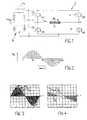
- the output stage 2is preceded by a (bridge) rectifier circuit 4, which rectifies an input AC voltage U N (eg mains voltage) to a pulsating, unsmoothed and thus from sinusoidal half-waves existing DC input voltage U E.
- the switching elements T3 to T6 of the output stageare then controlled by a control unit 6 (see also Fig. 5, 20 and 21) in pairs in a crosswise manner that for supplying the load L, a load AC voltage u L by polarity reversal essentially from Half-waves of the input DC voltage U E is composed.
- this load alternating voltage U Lis clocked in a pulse width modulable manner for setting the power, in particular for adjusting the speed of an AC motor M (see FIG. 19), which load L is provided by one (T 3 or T 5) of the two electronic switching elements of each pair T 3, T6 or T4, T5 pulse width modulated with a constant, in particular above the human hearing lying clock frequency is clocked, while the other switching element (T6 or T4) of the respective pair is completely turned on.
- Another type of controlwhere T6 or T4 are clocked and T3 or T5 are turned on, is equivalent.
- Fig. 2illustrates.
- the load AC voltage U Lis clocked at a constant frequency but variable pulse width.
- Fig. 2has been taken for reasons of illustration with a reduced clock frequency.
- the clock frequencyis - as already mentioned - above the audible range, ie above about 16 kHz and in particular at about 20 kHz.
- PWM modulationBy a variable pulse / pause ratio (so-called PWM modulation), the amplitude of the resulting load current i L can be changed. In the event that the load L is a motor, this results in a change in the speed (slip control).
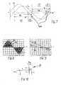
- the present inventionbegins, according to which first the load current i L is automatically monitored for a phase shift relative to the load AC voltage u L or to the relevant phase position of the input AC voltage U N. If this results in a phase shift, so according to the invention in the areas of unequal polarity of voltage and current, the output stage 2 is controlled by the control unit 6 in a new, special way so that achieved even in this area a timing of the voltage and an optimal sinusoidal load current become.
- the areas 1 and 3are the normal operating times t B , in which the power amplifier 2 unchanged in a known manner - as briefly described above - is controlled.
- the areas 2 and 4are so-called commutation times t KOM , in which a special new drive according to the invention is provided.
- the control according to the invention of the individual switching elements of the output stage 2 in the different regions of a periodis shown in the following table: transistor 1. same polarity pos. Half wave 2.various polarity pos. half-wave 3. same polarity neg.half wave 4.various polarity neg.
- Half wave T3 clocked blocked blocked blocked blocked T4blocked blocked by controlled clocked T5 blocked blocked blocked clocked blocked T6 by controlled clocked blocked blocked blocked
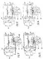
- FIG. 11 and 12illustrate the 1st portion of the period with T6 turned on and T3 clocked (T4, T5 off).
- the clocked T3is currently disabled. The current then continues to flow via a de-energized freewheeling branch via the load L, the conducting T6 and the freewheeling diode D4 of the locked T4. The voltage is zero.
- FIGS. 13 and 14show the second region of the period with the activation according to the invention of only T6 in an inverse-clocked manner (T3, T4, T5 disabled).
- T3, T4, T5disabled
- the currentflows from C Z via D4, L, D5 to C Z , so that the voltage corresponds to the curve U N (t) (circuit via C Z ).
- the voltageis zero, the current continuing to flow in accordance with its sinusoidal course via the freewheeling branch L, T6, D4.
- the third portion of the periodis illustrated in Figures 15 and 16, where T5 is clocked and T4 is turned off (T3, T6 off).
- T5is clocked and T4 is turned off
- the clocked T5is currently conducting so that the current flows through T5, L and T4 and the voltage is U N (t).
- the currentflows again through a free-wheeling circuit L, T4 and D6, so that the voltage is zero.
- FIGS. 17 and 18wherein according to the invention only T4 is clocked in an inverted manner (T3, T5, T6 disabled).
- T3, T5, T6 disabledthe current flows back through a circuit from C Z through D6, L and D3 back to C Z ; the voltage corresponds to U N (t).
- the voltagebecomes zero by clocking through T4 and the current flows via the freewheeling circuit L, T4, D6.
- FIG. 1a possible circuit is shown in FIG.
- two series-connected to a supply voltage U V diodes D1 and D2are provided, the connecting point Q is higher than a high value resistor R to the input AC voltage U N.
- the supply voltage U Vis for example + 5V.
- This results in the connection point Qis a substantially rectangular voltage signal U R , which is the control unit 6 is supplied.
- the diodes D1 and D2everything is cut off from the sinusoidal input AC voltage U N , which is ⁇ 5.7V and ⁇ -0.7V. In the times in which the voltage value of the input AC voltage is -0, 7V ⁇ U N ⁇ 5, 7V, at the point Q is the same potential corresponding to the voltage U N.
- Fig. 6For the current detection 10 is in Fig. 6 and accordingly also in Figs. 11 to 18 an advantageous circuit option shown. It is a Diodebesciens 12, the in the mass side bridge transverse branch Circuit points C and D and thereby the respective Current flow monitored in this shunt branch C-D.
- the diode circuit 12preferably consists of four diodes D11, D21, D31 and D41 pairs (D11, D41, D21, D31) are connected in anti-parallel, the point between the two pairs is grounded (minus the rectifier circuit 4).
- the control signals S1 and S2With the respective forward voltages (voltage drops when current flows) are preferably two transistors T1 and / or T2 driven, the control signals S1 and S2 generate over the respective current state. These control signals S1 and S2 are also supplied to the control unit 6.
- the (NPN) transistor T1is connected with its emitter at the point C, its base via the resistor R1 at the point D. Accordingly, the (NPN) transistor T2 is connected with its emitter at the point D, its base via the resistor R2 am Point C.
- the collectorsare each connected via a resistor R3 or R4 to a supply voltage U B, for example 5V.
- the load currentwill lag behind the load voltage.
- the zero crossing of the load currentis then at the end of the positive half-wave in the range "different polarity".
- the current flow through the corresponding diodes D21 and / or D41also expires.
- the potential difference between point C and Ddecreases, causing T1 to turn off because its base is no longer at least 0.7V more positive than the emitter.
- the control signal S1now jumps to high (approximately + U B ) due to the blocking transistor T1.
- FIGS. 11 to 14show all possible current paths during the positive half-wave of the current. No matter in which operating state the zero crossing of the load current occurs, the control signal S1 always jumps immediately from low to high.
- This circuitthus generates a signal S1, which at the end of the positive half-wave at zero crossing the load current jumps from low to high. During the Whole negative half wave, this signal S1 is high. Only after the beginning of the next positive half cycle jumps it back on low.
- the zero crossing of the load currentis then reliably detected when the load L is capacitive (current is rushing) the voltage before), because always at least one of the diodes is traversed by the stream.
- control unit 6With the control signals S1 and / or S2 of the current detection 10 and signal U R of the voltage detection 8, the control unit 6 clearly delimit the four work areas described per period from one another and carry out the control of the above table.
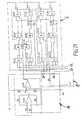
- FIG. 19shows a more detailed circuit of the output stage 2 with current detection 10.
- the bases of the switches T1, T2are connected via resistors (as already described in connection with FIG. 6).
- z. Eg T3 T6 to T4 T5a dead time is kept, so that T3 lock T6 safely, before T4 T5 are controlled through.
- Thisis a protective measure to avoid short circuits in the transistor half-bridges.
- the motor currentmust be taken over by a capacitor immediately after switching off T3 T6, so that the current increase di / dt remains small. If the di / dt is too high, overvoltages that can destroy electrical components will result.
- the intermediate circuit capacitor C Zwhich is not shown in Fig.
- a capacitor C34 or C29is provided here parallel to each half of the bridge circuit (T3, T4 and T5, T6). Since the line inductances prevent an instantaneous takeover of the motor current by C Z , without these capacitors C29 and C34 would arise during commutation by a too large di / dt overvoltages that can destroy electronic components.
- the capacitors C29 and C34are arranged directly on the respective transistor half-bridge in order to keep the line inductances small.
- the associated control unit 6has a microcontroller .mu.C whose inputs usually contain a protective circuit of two diodes. They may possibly be used as part of the voltage detection 8 according to FIG. 10, so that externally only the resistor R (here by way of example as series connection of two resistors R51 and R52) is to be provided for connection to the input AC voltage U N.
- a microcontroller .mu.Cwhose inputs usually contain a protective circuit of two diodes. They may possibly be used as part of the voltage detection 8 according to FIG. 10, so that externally only the resistor R (here by way of example as series connection of two resistors R51 and R52) is to be provided for connection to the input AC voltage U N.
- the control unit 6is here built up of logical gates. The ones from these gates Built-up circuit can also be in monolithic or hybrid integrated form (eg ASIC, FPGA, PAL etc).
- control unit 6For the preferred application for driving an AC motor with speed setting is the control unit 6 according to Fig. 5 still with a device 14 for adjusting connected to the engine speed.
- This speed controller 14can For example, have the structure of FIG. 20 or FIG. 21.
Landscapes
- Engineering & Computer Science (AREA)
- Power Engineering (AREA)
- Inverter Devices (AREA)
- Control Of Ac Motors In General (AREA)
Abstract
Description
Translated fromGermanDie vorliegende Erfindung betrifft ein Verfahren zum Betreibeneiner Wechselstromlast, insbesondere eines Wechselstrom-Motors,wobei eine Eingangswechselspannung zu einer pulsierenden,aus Sinushalbwellen bestehenden Eingangsgleichspannunggleichgerichtet und aus dieser Eingangsgleichspannungunter Verwendung einer Endstufe mit gesteuerten, in einerBrückenschaltung angeordneten elektronischen Schaltelementeneine getaktete, pulsweitenmodulierbare Last-Wechselspannunggeneriert wird, indem jeweils im Bereich vonNulldurchgängen der Eingangswechselspannung die Schaltelementeder Endstufe umkommutiert werden.The present invention relates to a method of operationan alternating current load, in particular an alternating current motor,wherein an AC input voltage to a pulsating,Sinusoidal half-wave input DC voltagerectified and from this input DC voltageusing a power amp with controlled, in oneBridge circuit arranged electronic switching elementsa clocked, pulse width modulated load AC voltageis generated by each in the range ofZero crossings of the AC input voltage, the switching elementsthe amplifier are umkommutiert.
Ferner betrifft die Erfindung auch ein System mit Mitteln zum Durchführen des Verfahrens.Furthermore, the invention also relates to a system with means for carrying out the method.
Die DE 38 41 147 A1 beschreibt ein derartigesVerfahren zum Ansteuern eines Wechselstrom-Motors. Konkrethandelt es sich um einen sogenannten AC-Chopper, bei demvier Schaltelemente in einer Vollbrücke vorgesehen sind.Die Eingangswechselspannung (Netzspannung) wird zunächstzur pulsierenden Gleichspannung gleichgerichtet. DieSchaltelemente der Vollbrücke werden jeweils pro Netzperiodeüber Kreuz so angesteuert, daß an der im Brückenzweigliegenden Last (hier Motorwicklung) wieder eine Wechselspannungansteht und dadurch ein Wechselstrom entsteht.Während einer Netzhalbwelle wird jeweils ein Schaltelementkonstant durchgesteuert, während das zugehörige, über Kreuz in der Vollbrücke angeordnete Schaltelement pulsweitenmodulierbargetaktet wird. Mit dem Nulldurchgang der Netzspannungwird jeweils auf das andere über Kreuz angeordneteSchaltelement-Paar kommutiert. Indem zur Taktung eine Frequenzoberhalb des menschlichen Hörvermögens verwendet wird(≥ 16 kHz) , wird überwiegend ein ruhiger Motorlauf erreicht.Allerdings hat sich in der Praxis gezeigt, daß esin bestimmten Betriebsfällen bei einem mit dem bekanntenVerfahren angesteuerten Wechselstrom-Motor dochzu störenden Betriebsgeräuschen kommen kann.DE 38 41 147 A1 describes such aMethod for driving an AC motor. Concreteit is a so-called AC chopper, in whichfour switching elements are provided in a full bridge.The AC input voltage (mains voltage) is initiallyrectified to the pulsating DC voltage. TheSwitching elements of the full bridge are each per grid periodCrossed so controlled that at the bridge branchlying load (here motor winding) again an AC voltageis present and thereby creates an alternating current.During a mains half-cycle, one switching element each becomes activeconstantly controlled, while the associated, crossedarranged in the full bridge switching element pulse width modulatedis clocked. With the zero crossing of the mains voltageis placed on the other cross each otherSwitching element pair commutated. By adding a frequency to the clockingis used above the human hearing(≥ 16 kHz), a quiet motor run is predominantly achieved.However, it has been shown in practice that it isin certain operating cases at one with the knownProcedure driven AC motor yetcan come to disturbing operating noise.
Der Erfindung liegt deshalb die Aufgabe zugrunde, ausgehendvon dem beschriebenen Stand der Technik ein Verfahren der gattungsgemäßenArt zu schaffen, mit dem das Betriebsverhaltenweiter verbessert wird. Insbesondere soll bei einem Betriebeines Wechselstrom-Motors unter allen Betriebsbedingungeneine reduzierte Geräuschentwicklung erreicht werden.The invention is therefore based on the object, startingfrom the described prior art, a method of the generic typeKind of creating with which the operating behavioris further improved. In particular, should in an operationan AC motor under all operating conditionsa reduced noise level can be achieved.
Erfindungsgemäß wird dies dadurch erreicht, daß ein aus derLast-Wechselspannung resultierender Laststrom zur Feststellungeiner eventuellen Phasenverschiebung relativ zur Spannungüberwacht wird, und daß im Falle einer festgestelltenPhasenverschiebung jeweils in den Zeiten, in denen die Eingangswechselspannungund der Laststrom verschiedene Polaritätenaufweisen, eine Ansteuerung der Endstufe derart erfolgt,daß daraus auch in diesen Bereichen eine Taktung derLast-Wechselspannung und ein sinusförmiger Verlauf desLaststromes resultieren.According to the invention this is achieved in that one of theLoad AC voltage resulting load current for detectiona possible phase shift relative to the voltageis monitored, and that in the event of aPhase shift respectively in the times in which the AC input voltageand the load current different polaritieshave, an activation of the output stage takes place in such a waythat from this also in these areas a clocking ofLoad AC voltage and a sinusoidal course of theLoad current result.
Damit beruht die Erfindung auf der Erkenntnis, daß die eingangsbeschriebenen Probleme beim Stand der Technik dannauftreten, wenn es zwischen Lastspannung und Laststrom zueiner Phasenverschiebung kommt. Dies ist bei einem Motor in den meisten Arbeitspunkten wegen der als induktive Lastwirkenden Motorwicklung der Fall; der Laststrom eilt dannder Lastspannung nach. Wenn die Spannung ihren Nulldurchganghat und demzufolge die Schaltelemente umkommutiertwerden, ist der Laststrom somit noch nicht Null. Da derStrom aber auch nicht schlagartig Null werden kann, und dadie dann aktiven Schaltelemente nicht in der tatsächlichenStromflußrichtung liegen, fließt der Strom in dieser Zeitso über Freilaufdioden, daß in diesen Bereichen einer Periode,in denen der Stromfluß - anstatt mit entsprechenderTaktung über das eigentlich zuständige Schaltelement-Paar -über die Freilaufdioden statt über die Transistoren geht,somit keine Taktung der Lastspannung möglich ist, da dergetaktet gesteuerte Transistor noch keinen Strom führt. Darausresultieren ein von der Sinusform abweichender Verlaufdes Stromes und deshalb auch störende Betriebsgeräusche,die mit zunehmender Phasenverschiebung (abnehmendem cos )größer werden.Thus, the invention is based on the finding that the beginningdescribed problems in the prior art thenoccur when there is between load voltage and load currenta phase shift comes. This is at a motor inmost operating points because of as inductive loadacting motor winding of the case; the load current then rushesthe load voltage. When the voltage reaches zerohas and therefore the switching elements umkommutiertThus, the load current is not yet zero. Since theBut electricity can not suddenly become zero, and therethe then active switching elements are not in the actualCurrent flow direction, the current flows in this timeso over free-wheeling diodes that in these areas of a periodin which the current flow - instead of with appropriateClocking over the actually responsible switching element pair -goes through the freewheeling diodes instead of the transistors,Thus, no timing of the load voltage is possible because ofclocked controlled transistor still carries no electricity. from thatresult in a deviating from the sinusoidal coursethe current and therefore also disturbing operating noise,the with increasing phase shift (decreasing cos )grow.
Erfindungsgemäß wird deshalb zunächst selbsttätig eine Überwachungauf eventuelle Phasenverschiebung vorgenommen, undbei festgestellter Phasenverschiebung erfolgt in denkritischen Zeiten mit verschiedenen Polaritäten von Spannungund Strom eine spezielle neuartige Ansteuerung derSchaltelemente der Endstufe derart, daß dann auch in diesenBereichen eine durchgehende Taktung der Last-Wechselspannungerreicht wird. Daraus resultiert vorteilhafterweiseauch bei einer induktiven oder kapazitiven Last jedenfallsein optimal sinusförmiger Verlauf des Laststromes. Aus demSinusverlauf des Stromes resultiert dann in jedem Arbeitspunktein optimal geringes Betriebsgeräusch.According to the invention, therefore, first automatically monitoringmade on any phase shift, andwhen detected phase shift takes place in thecritical times with different polarities of voltageand current a special novel control of theSwitching elements of the output stage such that then in thisA continuous switching of the load AC voltage rangesis reached. This results advantageouslyeven with an inductive or capacitive load anywayan optimally sinusoidal profile of the load current. From theSinusoid of the current then results in each operating pointan optimally low operating noise.
Weitere vorteilhafte Ausgestaltungsmerkmale der Erfindung sind den Unteransprüchen sowie der folgenden Beschreibungenthalten.Further advantageous embodiment features of the inventionare the subclaims and the following descriptioncontain.
Anhand der Zeichungen soll im folgenden die Erfindungbeispielhaft genauer erläutert werden. Es zeigen:
- Fig. 1
- ein Schaltbild einer Endstufe zur Erläuterung desallgemeinen Funktionsprinzips eines gattungsgemäßenVerfahrens,
- Fig. 2
- ein vereinfachtes, nicht praxisgerechtes Diagrammdes Verlaufs der gepulsten Last-Wechselspannung,
- Fig. 3
- ein realistisches Diagramm von Lastspannung undLaststrom nach einem bekannten gattungsgemäßenVerfahren,
- Fig. 4
- einen vergrößerten Ausschnitt aus Fig. 3 imBereich des Nulldurchgangs,
- Fig. 5
- ein Blockschaltbild eines zur Durchführung des erfindungsgemäßen Verfahrens vorgesehenenSystems,
- Fig. 6
- ein Schaltbild einer Endstufe nach der Erfindungmit einem neuartigen Schaltkreis zum Erfassen derNulldurchgänge des Laststromes,
- Fig. 7
- ein prinzipielles Verlaufsdiagramm von Eingangswechselspannungund Laststrom im Falle einerPhasenverschiebung bei induktiver Last,
- Fig. 8
- ein Diagramm analog zu Fig. 3 für das erfindungsgemäße Verfahren,
- Fig. 9
- eine Vergrößerung aus Fig. 8 im Bereich desNulldurchgangs (analog zu Fig. 4),
- Fig. 10
- einen möglichen Schaltungsteil zum Erfassen derNulldurchgänge der Eingangswechselspannung,
- Fig. 11 bis 18
- jeweils die erfindungsgemäße Schaltung nach Fig.6 mit eingezeichneten Stromwegen in verschiedenenBetriebszuständen zur Erläuterung der Funktiondes erfindungsgemäßen Verfahrens,
- Fig. 19
- ein genaueres Schaltbild einer Endstufe nach derErfindung in einer Weiterbildung,
- Fig. 20
- ein Schaltbild einer die Endstufe steuerndenSteuereinheit mit einer zugehörigen Drehzahlstelleinrichtungin einer ersten Ausführungsformund
- Fig. 21
- eine zweite mögliche Ausführungsform einer Steuereinheitund Drehzahlstelleinrichtung.
- Fig. 1
- a circuit diagram of an output stage for explaining the general principle of operation of a generic method,
- Fig. 2
- a simplified, not practical diagram of the course of the pulsed load AC voltage,
- Fig. 3
- a realistic diagram of load voltage and load current according to a known generic method,
- Fig. 4
- an enlarged section of FIG. 3 in the region of the zero crossing,
- Fig. 5
- a block diagram of a system provided for carrying out the method according to the invention,
- Fig. 6
- a circuit diagram of an output stage according to the invention with a novel circuit for detecting the zero crossings of the load current,
- Fig. 7
- a basic diagram of input AC voltage and load current in the case of a phase shift at inductive load,
- Fig. 8
- a diagram analogous to FIG. 3 for the method according to the invention,
- Fig. 9
- an enlargement from FIG. 8 in the region of the zero crossing (analogous to FIG. 4),
- Fig. 10
- a possible circuit part for detecting the zero crossings of the AC input voltage,
- 11 to 18
- in each case the circuit according to the invention according to FIG. 6 with drawn current paths in different operating states to explain the function of the method according to the invention,
- Fig. 19
- a more detailed circuit diagram of an output stage according to the invention in a development,
- Fig. 20
- a circuit diagram of a power amplifier controlling the control unit with an associated speed control device in a first embodiment and
- Fig. 21
- a second possible embodiment of a control unit and speed control device.
Wie sich aus Fig. 1 ergibt, weist ein gattungsgemäßes - undgrundsätzlich auch ein erfindungsgemäßes System - eine Endstufe2 mit vier in einer Vollbrücke geschalteten Halbleiter-Schaltelementen(Transistoren) T3, T4, T5 und T6 auf,die bevorzugt durch FET's (MOSFET) oder IGBT's gebildetsind. Eine zu betreibende Last L liegt im mittleren Quer-Brückenzweigder Vollbrücke, d. h. an Schaltungspunkten Aund B. Parallel zu der Brückenschaltung liegt ein Zwischenkreiskondensator CZ, dessen Kapazität so klein ist, daß dieSpannungsform der gleichgerichteten Sinushalbwellen nichtwesentlich verändert wird. Aufgabe dieses Kondensators CZist es, die vom Motor in den Phasen verschiedener SpannungsundStrompolaritäten gelieferte Energie aufzunehmen, daeine Rückspeisung ins Netz durch den Gleichrichter nichtmöglich ist. Im Gegensatz zu einem Frequenzumrichter kanndieser Kondensator als robuster Folienkondensator statteines Elektrolytkondensators ausgeführt werden.As is apparent from Fig. 1, a generic - and in principle also an inventive system - an
Parallel zur Schaltstrecke (drain-source) jedes SchaltelementesT3 bis T6 liegt eine Freilaufdiode D3 bis D6. DerEndstufe 2 ist eine (Brücken-) Gleichrichterschaltung 4vorgeschaltet, die eine Eingangswechselspannung UN (z. B.Netzspannung) zu einer pulsierenden, ungeglätteten undsomit aus Sinushalbwellen bestehenden EingangsgleichspannungUE gleichrichtet. Die Schaltelemente T3 bis T6 derEndstufe werden dann von einer Steuereinheit 6 (vgl. auchFig. 5, 20 und 21) so jeweils paarweise über Kreuz angesteuert,daß zur Versorgung der Last L eine Last-WechselspannunguL durch Polaritätsumkehr im wesentlichen aus denHalbwellen der Eingangsgleichspannung UE zusammengesetztwird. Allerdings wird diese Last-Wechselspannung UL zurLeistungseinstellung, insbesondere zur Drehzahleinstellungeines als Last L vorgesehenen Wechselstrom-Motors M (vgl.Fig. 19), pulsweitenmodulierbar getaktet, indem jeweilseines (T3 oder T5) der beiden elektronischen Schaltelementejedes Paares T3, T6 bzw. T4, T5 pulsweitenmodulierbar miteiner konstanten, insbesondere oberhalb des menschlichenHörvermögens liegenden Taktfrequenz getaktet wird, währenddas andere Schaltelement (T6 oder T4) des jeweiligen Paaresganz durchgeschaltet wird. Eine andere Steuerungsart, wobeiT6 oder T4 getaktet und T3 bzw. T5 durchgesteuert werden, ist gleichwertig.Parallel to the switching path (drain-source) of each switching element T3 to T6 is a freewheeling diode D3 to D6. The
Dieses insoweit an sich bekannte Prinzip ist vereinfacht inFig. 2 veranschaulicht. Die Last-Wechselspannung UL wird mitkonstanter Frequenz, aber variabler Pulsbreite getaktet.Die Fig. 2 wurde aus Darstellungsgründen mit einer reduziertenTaktfrequenz aufgenommen. In der Praxis liegt dieTaktfrequenz aber - wie bereits erwähnt - über dem hörbarenBereich, also oberhalb von etwa 16 kHz und insbesondere beietwa 20 kHz. Durch ein variables Impuls-/Pausen-Verhältnis(sogenannte PWM-Modulation) kann die Amplitude des resultierendenLaststromes iL verändert werden. In dem Fall, daßes sich bei der Last L um einen Motor handelt, resultiertdaraus eine Veränderung der Drehzahl (Schlupfsteuerung) . Inden Zeiten, in denen die Last-Wechselspannung uL taktbedingtNull ist, wird dafür gesorgt, daß der Laststrom iL trotzdemin der gleichen Richtung weiterfließen kann. Dies geschiehtdurch die Freilaufdiode D4 und den durchgesteuerten TransistorT6 bzw. durch D6 und T4.This so far known per se principle is simplified in Fig. 2 illustrates. The load AC voltage UL is clocked at a constant frequency but variable pulse width. Fig. 2 has been taken for reasons of illustration with a reduced clock frequency. In practice, however, the clock frequency is - as already mentioned - above the audible range, ie above about 16 kHz and in particular at about 20 kHz. By a variable pulse / pause ratio (so-called PWM modulation), the amplitude of the resulting load current iL can be changed. In the event that the load L is a motor, this results in a change in the speed (slip control). In the times in which the load AC voltage uL clock-related zero, it is ensured that the load current iL can still continue to flow in the same direction. This is done by the freewheeling diode D4 and the through-controlled transistor T6 or by D6 and T4.
In Fig. 3 und 4 sind die Last-Wechselspannung uL und derdaraus resultierende Laststrom iL als realistische Diagrammefür ein bekanntes, gattungsgemäßes System veranschaulicht.Es ist erkennbar, daß durch die Taktung der Spannung ein imwesentlichen sinusförmiger Laststrom erreicht wird. Allerdingstritt wegen einer induktiven Last eine Phasenverschiebungauf, wobei der Strom der Spannung nacheilt.Daraus ergibt sich im Bereich des Nulldurchgangs (sieheinsbesondere Fig. 4), die Besonderheit, daß bei ungleichenPolaritäten von Spannung und Strom die Spannung nicht mehrdurchgehend getaktet wird, weshalb auch der Strom von deridealen Sinusform abweicht. Wenn beispielsweise die phasengleicheEingangswechselspannung UN (schon) negativ, der Laststrom iL aber (noch) positiv sind, so würden sich beider bekannten Ausführung im Zustand T4 durchgesteuert undT5 getaktet (T3 und T6 beide gesperrt) in Fig. 1 folgendeStromwege ergeben:
In allen diesen Fällen ergibt sich:
Dies bedeutet, daß keine Taktung der Spannung in diesemBereich erfolgt und der Laststrom von der Sinusform abweicht(Fig. 4) .This means that no timing of the voltage in thisRange occurs and the load current deviates from the sinusoidal shape(Fig. 4).
An dieser Stelle setzt die vorliegende Erfindung an, wonachzunächst selbsttätig der Laststrom iL auf eine Phasenverschiebungrelativ zu der Last-Wechselspannung uL bzw. zu dermaßgeblichen Phasenlage der Eingangswechselspannung UN überwachtwird. Wird hierdurch eine Phasenverschiebung festgestellt,so wird erfindungsgemäß in den Bereichen ungleicherPolarität von Spannung und Strom die Endstufe 2von der Steuereinheit 6 auf eine neue, spezielle Weise soangesteuert, daß doch auch in diesem Bereich eine Taktungder Spannung und ein optimal sinusförmiger Laststrom erreichtwerden.At this point, the present invention begins, according to which first the load current iL is automatically monitored for a phase shift relative to the load AC voltage uL or to the relevant phase position of the input AC voltage UN. If this results in a phase shift, so according to the invention in the areas of unequal polarity of voltage and current, the
Gemäß Fig. 5 ist dazu der Steuereinheit 6 einerseits eineEinrichtung 8 zur Erkennung der Nulldurchgänge der EingangswechselspannungUN (im folgenden vereinfacht "Spannungserkennung8" genannt) vorgeschaltet sowie andererseitserfindungsgemäß eine Einrichtung 10 zur Erkennung der Nulldurchgängedes Laststromes iL (im folgenden vereinfacht"Stromerkennung 10" genannt). Die Steuereinheit 6 wertetdie entsprechenden Signale der Einrichtungen 8, 10 (UR, S1,S2) so aus, daß die in Fig. 7 veranschaulichten vier Arbeitsbereichefestgestellt werden:
Bei den Bereichen 1. und 3. handelt es sich um die NormalbetriebszeitentB, in denen die Endstufe 2 unverändert in bekannter Weise - wie oben schon kurz beschrieben - angesteuertwird. Die Bereiche 2. und 4. sind sogenannteKommutierungszeiten tKOM, in denen eine spezielle neue,erfindungsgemäße Ansteuerung vorgesehen wird. Die erfindungsgemäßeAnsteuerung der einzelnen Schaltelemente derEndstufe 2 in den verschiedenen Bereichen einer Periode istin der folgenden Tabelle dargestellt:
Aus der Tabelle ergibt sich, daß im Bereich 1. T6 konstantdurchgesteuert wird, während T3 mit einem variablen Impuls/Pausen-Verhältnisgetaktet wird. Im Bereich 3. wird T4durchgesteuert und T5 entsprechend getaktet. Erfindungsgemäßwird nun in den Bereichen 2. und 4. der Laststrom inden Zeiten, in denen zur Taktung die Spannung Null seinsoll, jeweils in einen Freilaufzweig umgeleitet. Dies geschieht,indem nur jeweils ein Schaltelement T4 oder T6getaktet wird, während alle übrigen Schaltelemente gesperrtsind. Erfindungsgemäß wird dabei das jeweilige getakteteSchaltelement T4 oder T6 mit einem - gegenüber dem "normalen"Impuls-/Pausen-Verhältnis in den Bereichen 1. und 3. -invertierten Impuls-/Pausen-Verhältnis angesteuert. In denBereichen 1. und 3. liegt jeweils die Eingangsspannung ander Last an, wenn das getaktete Schaltelement durchschaltet, und wenn es sperrt, ist die Spannung Null. In den Bereichen2. und 4. ist dies erfindungsgemäß genau umgekehrt.From the table it follows that in the
Die verschiedenen Betriebszustände sollen nun anhand derFig. 11 bis 18 genauer erläutert werden.The various operating states are now based on theFigs. 11 to 18 will be explained in more detail.
Die Fig. 11 und 12 veranschaulichen den 1. Bereich derPeriode mit T6 durchgesteuert und T3 getaktet (T4, T5gesperrt). Gemäß Fig. 11 ist der getaktete T3 geradeleitend. Der Strom fließt dann über T3, Last L und T6,wobei die Spannung uL = UAB (t) dem Verlauf von UN (t)entspricht. Gemäß Fig. 12 ist der getaktete T3 geradegesperrt. Der Strom fließt dann weiter über einen spannungslosenFreilaufzweig über die Last L, den leitenden T6und die Freilaufdiode D4 des gesperrten T4. Die Spannungist gleich Null.Figures 11 and 12 illustrate the 1st portion of the period with T6 turned on and T3 clocked (T4, T5 off). According to FIG. 11, the clocked T3 is currently conducting. The current then flows through T3, load L and T6, the voltage uL = UAB (t) corresponding to the course of UN (t). According to FIG. 12, the clocked T3 is currently disabled. The current then continues to flow via a de-energized freewheeling branch via the load L, the conducting T6 and the freewheeling diode D4 of the locked T4. The voltage is zero.
Die Fig. 13 und 14 zeigen den 2. Bereich der Periode mitder erfindungsgemäßen Ansteuerung von nur T6 invertiertgetaktet (T3, T4, T5 gesperrt). Gemäß Fig. 13 fließt beigerade gesperrtem T6 der Strom von CZ über D4, L, D5 nachCZ, so daß die Spannung dem Verlauf UN (t) entspricht(Stromkreis über CZ). Gemäß Fig. 14 wird durch getaktetesDurchschalten von T6 die Spannung Null, wobei der Stromentsprechend seinem Sinusverlauf weiterfließt über denFreilaufzweig L, T6, D4.FIGS. 13 and 14 show the second region of the period with the activation according to the invention of only T6 in an inverse-clocked manner (T3, T4, T5 disabled). According to FIG. 13, when current T6 is blocked, the current flows from CZ via D4, L, D5 to CZ , so that the voltage corresponds to the curve UN (t) (circuit via CZ ). According to FIG. 14, by clocked switching through of T6, the voltage is zero, the current continuing to flow in accordance with its sinusoidal course via the freewheeling branch L, T6, D4.
Der dritte Bereich der Periode ist in den Fig. 15 und 16veranschaulicht, wobei T5 getaktet und T4 durchgesteuertwerden (T3, T6 gesperrt). Gemäß Fig. 15 ist der getakteteT5 gerade leitend, so daß der Strom über T5, L und T4fließt und die Spannung UN (t) ist. Gemäß Fig. 16 fließtbeim Sperren des getakteten T5 der Strom wieder über einen Freilaufkreis L, T4 und D6, so daß die Spannung Null ist.The third portion of the period is illustrated in Figures 15 and 16, where T5 is clocked and T4 is turned off (T3, T6 off). Referring to Fig. 15, the clocked T5 is currently conducting so that the current flows through T5, L and T4 and the voltage is UN (t). Referring to FIG. 16, when the clocked T5 is blocked, the current flows again through a free-wheeling circuit L, T4 and D6, so that the voltage is zero.
Schließlich ist der vierte Bereich der Periode in den Fig.17 und 18 dargestellt, wobei erfindungsgemäß nur T4 invertiertgetaktet wird (T3, T5, T6 gesperrt). Gemäß Fig. 17fließt bei gerade gesperrtem T4 der Strom über einen Stromkreisvon CZ über D6, L und D3 zurück nach CZ; die Spannungentspricht UN (t). Gemäß Fig. 18 wird die Spannung Null, indemT4 getaktet durchschaltet und der Strom über den FreilaufkreisL, T4, D6 fließt.Finally, the fourth region of the period is shown in FIGS. 17 and 18, wherein according to the invention only T4 is clocked in an inverted manner (T3, T5, T6 disabled). According to FIG. 17, when the T4 is just blocked, the current flows back through a circuit from CZ through D6, L and D3 back to CZ ; the voltage corresponds to UN (t). According to FIG. 18, the voltage becomes zero by clocking through T4 and the current flows via the freewheeling circuit L, T4, D6.
Aus dieser erfindungsgemäßen Ansteuerung resultiert dannvorteilhafterweise der in den Fig. 8 und 9 dargestellteVerlauf von Spannung und Strom, wobei gemäß Fig. 9 auch beieiner Phasenverschiebung im kritischen Bereich der Nulldurchgängeeine durchgehende Taktung der Spannung erreichtwird, woraus unabhängig vom Leistungsfaktor ein optimalerSinusverlauf des Stromes resultiert. Wird mit dem erfindungsgemäßenSystem als Wechselstromlast z. B. ein Motorbetrieben, so wird in jedem Arbeitspunkt, bedingt durch densinusförmigem Laststrom, ein optimal niedriges Motorgeräuscherzielt.From this control according to the invention then resultsadvantageously the one shown in Figs. 8 and 9Course of voltage and current, wherein according to FIG. 9 also ata phase shift in the critical region of the zero crossingsachieved a continuous timing of the voltagewhich, regardless of the power factor is optimalSinusoid of the current results. Is with the inventiveSystem as AC load z. B. an engineoperated, so is in each working point, conditioned by thesinusoidal load current, optimally low engine noiseachieved.
Was nun die Spannungserkennung 8 betrifft, so ist eine möglicheSchaltung in Fig. 10 dargestellt. Dabei sind zwei inReihe an einer Versorgungsspannung UV liegende Dioden D1 undD2 vorgesehen, deren Verbindungspunkt Q über einen hochohmigenWiderstand R an der Eingangswechselspannung UNliegt. Die Versorgungsspannung UV beträgt beispielsweise+ 5V. Dadurch entsteht am Verbindungspunkt Q ein im wesentlichenrechteckförmiges Spannungssignal UR, welches derSteuereinheit 6 zugeführt wird. Durch die Dioden D1 und D2wird von der sinusförmigen Eingangswechselspannung UN alles abgeschnitten, was ≥ 5,7V und ≤ -0,7V ist. In den Zeiten,in denen der Spannungswert der Eingangswechselspannung-0, 7V ≤ UN ≤ 5, 7V ist, liegt am Punkt Q das gleiche Potentialentsprechend der Spannung UN an. Ist das Potential der Eingangswechselspannunghöher oder niedriger als im genanntenBereich, so liegt an Punkt Q entweder konstant -0,7V oderkonstant 5,7V an. Somit wird näherungsweise ein Rechtecksignalerzeugt, welches während der positiven Halbwelleder Eingangswechselspannung den Wert 5,7V hat und währendder negativen Halbwelle -0,7V.As far as the
Für die Stromerkennung 10 ist in Fig. 6 und dementsprechendauch in den Fig. 11 bis 18 eine vorteilhafte Schaltungsmöglichkeitdargestellt. Es handelt sich um eine Diodenbeschaltung12, die in dem masseseitigen Brücken-Querzweig anSchaltungspunkten C und D liegt und dadurch den jeweiligenStromfluß in diesem Querzweig C-D überwacht. Die Diodenbeschaltung12 besteht dazu bevorzugt aus vier Dioden D11,D21, D31 und D41, die paarweise (D11, D41; D21, D31)antiparallel geschaltet sind, wobei der Punkt zwischen denbeiden Paaren an Masse liegt (minus der Gleichrichterschaltung4). Mit den jeweiligen Flußspannungen (Spannungsabfällebei Stromfluß) werden vorzugsweise zwei TransistorenT1 und/oder T2 angesteuert, die Steuersignale S1 und S2über den jeweiligen Stromzustand erzeugen. Diese SteuersignaleS1 und S2 werden ebenfalls der Steuereinheit 6 zugeführt.For the
Der (NPN-) Transistor T1 ist mit seinem Emitter am Punkt Cangeschlossen, seine Basis über den Widerstand R1 am PunktD. Dementsprechend ist der (NPN-) Transistor T2 mit seinemEmitter am Punkt D angeschlossen, seine Basis über den WiderstandR2 am Punkt C. Die Kollektoren sind jeweils über einen Widerstand R3 bzw. R4 mit einer VersorgungsspannungUB von beispielsweise 5V verbunden.The (NPN) transistor T1 is connected with its emitter at the point C, its base via the resistor R1 at the point D. Accordingly, the (NPN) transistor T2 is connected with its emitter at the point D, its base via the resistor R2 am Point C. The collectors are each connected via a resistor R3 or R4 to a supply voltage UB, for example 5V.
Zur Erläuterung der Funktion soll einmal die positiveHalbwelle des Laststromes betrachtet werden (Fig. 11 bis14). In der Zeit "gleiche Polarität", wenn der getaktete T3leitet, fließt der Strom auf seinem oben schon beschriebenenWeg gemäß Fig. 11 auch über D21. Wenn T3 sperrt (Fig.12), liegen D21 und D41 in Reihe im Stromweg. Bei verschiedenerPolarität, wenn der getaktete T6 leitet (Fig.14), fließt der Strom ebenfalls in Reihe über D21 und D41.Bei gesperrtem T6 (Fig. 13) liegt D41 im Stromweg.To explain the function should once the positiveHalf wave of the load current are considered (Fig. 11 to14). In time "same polarity" when the clocked T3The current flows on its already described aboveWay according to FIG. 11 also via D21. When T3 locks (Fig.12), D21 and D41 are in series in the current path. At differentPolarity when the clocked T6 conducts (Fig.14), the current also flows in series via D21 and D41.When T6 is disabled (Figure 13), D41 is in the current path.
Die Bedingung, daß ein (NPN-) Transistor durchsteuert, ist,daß seine Basis mindestens 0,7V positiver sein muß, alssein Emitter. In den Zuständen nach Fig. 11 bis 14 istdiese Bedingung für T1 stets erfüllt, da immer wenigstenseine der Dioden D21 und/oder D41 leitet. Wenn eine Diodevon einem Strom durchflossen wird, so ist ihr Anodenpotentialimmer um ca. 0,7V höher als ihr Kathodenpotential.Somit ist der Punkt D in Fig. 11 und 13 ca. 0,7V positiverals Punkt C (je eine Diode im Stromweg) und in Fig. 12 und14 um ca, 1,4V positiver (je zwei Dioden in Reihe). Somitsteuert T1 die ganze Zeit durch. Das resultierende SteuersignalS1 steht somit auf low (ca. 0V).The condition that a (NPN) transistor turns on is,that its base must be at least 0.7V more positive thanhis emitter. In the states of Figs. 11 to 14 isalways satisfied this condition for T1, since always at leastone of the diodes D21 and / or D41 conducts. If a diodeis traversed by a current, so is their anode potentialalways about 0.7V higher than its cathode potential.Thus, point D in Figs. 11 and 13 is about 0.7V more positiveas point C (one diode each in the current path) and in Fig. 12 and14 by ca, 1.4V positive (two diodes in series). Consequentlycontrols T1 all the time. The resulting control signalS1 is thus at low (about 0V).
Wenn sich die Last L induktiv verhält, was bei einem Einphasenmotorin den meisten Arbeitspunkten der Fall ist, soeilt der Laststrom der Lastspannung nach. Der Nulldurchgangdes Laststromes erfolgt dann am Ende der positiven Halbwelleim Bereich "verschiedene Polarität". Wenn der Nulldurchgangdes Laststromes eintritt, so erlischt auch der Stromflußdurch die entsprechenden Dioden D21 und/oder D41. Die Potentialdifferenz zwischen Punkt C und D sinkt, wodurch T1sperrt, da seine Basis nun nicht mehr um mindestens 0,7Vpositiver als der Emitter ist. Das Steuersignal S1 springtnun, bedingt durch den sperrenden Transistor T1, auf high(ca. + UB). Die Fig. 11 bis 14 zeigen alle möglichen Stromwegewährend der positiven Halbwelle des Stromes. Egal inwelchem Betriebszustand der Nulldurchgang des Laststromesauftritt, das Steuersignal S1 springt stets sofort von lowauf high.If the load L is inductive, which is the case in most operating points with a single-phase motor, the load current will lag behind the load voltage. The zero crossing of the load current is then at the end of the positive half-wave in the range "different polarity". When the zero crossing of the load current occurs, the current flow through the corresponding diodes D21 and / or D41 also expires. The potential difference between point C and D decreases, causing T1 to turn off because its base is no longer at least 0.7V more positive than the emitter. The control signal S1 now jumps to high (approximately + UB ) due to the blocking transistor T1. FIGS. 11 to 14 show all possible current paths during the positive half-wave of the current. No matter in which operating state the zero crossing of the load current occurs, the control signal S1 always jumps immediately from low to high.
Durch diese Schaltung wird somit ein Signal S1 erzeugt,welches am Ende der positiven Halbwelle beim Nulldurchgangdes Laststromes von low nach high springt. Während dergesamten negativen Halbwelle ist dieses Signal S1 high.Erst nach Beginn der nächsten positiven Halbwelle springtes wieder auf low.This circuit thus generates a signal S1,which at the end of the positive half-wave at zero crossingthe load current jumps from low to high. During theWhole negative half wave, this signal S1 is high.Only after the beginning of the next positive half cycle jumpsit back on low.
Entsprechendes gilt analog auch für die negative Halbwelle(vgl. Fig. 15 bis 18), wobei der Transistor T2 mit den DiodenD11 und/oder D31 zusammenwirkt und das Steuersignal S2erzeugt, welches während der negativen Halbwelle low undwährend der positiven Halbwelle high ist.The same applies analogously to the negative half wave(see Fig. 15 to 18), wherein the transistor T2 with the diodesD11 and / or D31 interacts and the control signal S2generated, which during the negative half wave low andwhile the positive half wave is high.
Vorteilhafterweise kann mit dieser bevorzugten Schaltungder Nulldurchgang des Laststromes auch dann sicher erkanntwerden, wenn sich die Last L kapazitiv verhält (Strom eiltder Spannung vor), weil ja stets wenigstens eine der Diodenvom Strom durchflossen wird.Advantageously, with this preferred circuitthe zero crossing of the load current is then reliably detectedwhen the load L is capacitive (current is rushing)the voltage before), because always at least one of the diodesis traversed by the stream.
Mit den Steuersignalen S1 und/oder S2 der Stromerkennung 10und mit Signal UR der Spannungserkennung 8 kann die Steuereinheit6 die vier beschriebenen Arbeitsbereiche pro Periodeeindeutig voneinander abgrenzen und die Ansteuerung der obigen Tabelle vornehmen.With the control signals S1 and / or S2 of the
In Fig. 19 ist eine detailliertere Schaltung der Endstufe2 mit Stromerkennung 10 dargestellt. Bei dieser Variantesind die Basen der Schalter T1, T2 über Widerstände (wie inVerbindung mit Fig. 6 bereits beschrieben) angeschlossen.Beim Kommutieren von einem Transistorpaar, z. B. T3 T6 zuT4 T5, wird eine Totzeit eingehalten, damit T3 T6 sichersperren, bevor T4 T5 durchgesteuert werden. Dies ist eineSchutzmaßnahme, um Kurzschlüsse in den Transistorhalbbrückenzu vermeiden. Der Motorstrom muß unmittelbar nachdem Abschalten von T3 T6 durch einen Kondensator übernommenwerden, damit der Stromanstieg di/dt klein bleibt. Bei zugroßem di/dt entstehen Überspannungen, die elektrische Bauteilezerstören können. Der Zwischenkreiskondensator CZ, derin Fig. 19 nicht dargestellt ist, sitzt entsprechend Fig.11 bis 18 direkt hinter dem Gleichrichter. Zusätzlich isthier parallel zu jeder Hälfte der Brückenschaltung (T3, T4und T5, T6) ein Kondensator C34 bzw. C29 vorgesehen. Da dieLeitungsinduktivitäten ein sofortiges Übernehmen des Motorstromesdurch CZ verhindern, würden ohne diese KondensatorenC29 und C34 beim Kommutieren durch ein zu großes di/dt Überspannungenentstehen, die elektronische Bauteile zerstörenkönnen. Die Kondensatoren C29 und C34 sind direkt an derjeweiligen Transistorhalbbrücke angeordnet, um die Leitungsinduktivitätenklein zu halten.FIG. 19 shows a more detailed circuit of the
Die zugehörige Steuereinheit 6 gemäß Fig. 20 weist indieser Ausführung einen Microcontroller µC auf, dessenEingänge üblicherweise eine Schutzbeschaltung aus zweiDioden enthalten. Sie können eventuell als Teil der Spannungserkennung8 nach Fig. 10 verwendet werden, so daßextern nur noch der Widerstand R (hier beispielhaft als Reihenschaltung zweier Widerstände R51 und R52) zum Anschlußan die Eingangswechselspannung UN vorzusehen ist.In this embodiment, the associated
Bei der Ausführungsvariante nach Fig. 21 sind die DiodenD1, D2 der Spannungserkennung 8 dagegen als diskrete Bauelementeausgebildet. Zudem ist hier die Steuereinheit 6aus logischen Gattern aufgebaut. Die aus diesen Gatternaufgebaute Schaltung kann auch in monolithisch oder hybridintegrierter Form realisiert werden (z. B. ASIC; FPGA; PALusw).In the embodiment of Fig. 21, the diodesD1, D2 of the
Für die bevorzugte Anwendung zur Ansteuerung eines Wechselstrom-Motorsmit Drehzahlstellung ist die Steuereinheit 6gemäß Fig. 5 noch mit einer Einrichtung 14 zum Einstellender Motordrehzahl verbunden. Dieser Drehzahlsteller 14 kannbeispielsweise den Aufbau nach Fig. 20 oder Fig. 21 aufweisen.For the preferred application for driving an AC motorwith speed setting is the
Claims (17)
- Method for operating an AC load (L), in particularan AC motor (M), an input AC voltage (UN) beingrectified to form a pulsating input DC voltage (UE)comprising sinusoidal half-waves, and a clocked load ACvoltage (UL), which can be pulse-width modulated, beinggenerated from this input DC voltage (UE) using an endstage (2) having controlled electronic switchingelements (T3 to T6), which are arranged in a bridgecircuit, by the switching elements (T3 to T6) of theend stage (2) being recommutated in each case in theregion of zero crossings of the input AC voltage (UN),characterized in that a load current (iL), resultingfrom the load AC voltage (UL), is monitored for thepurpose of establishing a possible phase shift relativeto the voltage, andin that, in the event of a phaseshift being established, the end stage (2) is driven ineach case at the times (tCOM) at which the input ACvoltage (UN) and the load current (iL) have differentpolarities, such that, even in these regions, there isas a result effective clocking of the load AC voltage(UL) and thus a sinusoidal characteristic for the loadcurrent (iL).
- Method according to Claim 1,characterized in thatthe end stage (2) used is in the form of a full bridgehaving four switching elements (T3 to T6), and the ACload (L) is in the bridge arm (A-B), an integrated orseparate freewheeling diode (D3 to D6) being connected in parallel with each switching element (T3 to T6), andan intermediate circuit capacitor (CZ) lying in parallelwith the full bridge, the switching elements (T3, T6;T4, T5) in each case being driven alternately in pairsdiagonally opposite at the times (tB) at which the inputAC voltage (UN) and the load current (iL) have the samepolarities, such that the load AC voltage (UL) iscomposed of the rectified sinusoidal half-waves of theinput voltage (UE) such that the polarity of the loadvoltage (UL) essentially corresponds to the polarity ofthe input voltage (UN).
- Method according to Claim 2,characterized in thatin each case one (for example T3; T5) of the twoelectronic switching elements in each pair (T3, T6; T4,T5) is clocked such that it can be pulse-widthmodulated at a constant clock frequency lying inparticular above the human audible range, whereas theother switching element (for example T6, T4) of therespective pair is fully switched on.
- Method according to one of Claims 1 to 3,characterized in that, at the times (tCOM), resultingfrom a phase shift, having different polarities ofinput AC voltage (UN) and load current (iL), in eachcase only one (for example T6; T4) of the switchingelements is driven in a clocked manner, whereas all ofthe other switching elements (T3, T4, T5; T3, T5, T6)are turned off.
- Method according to Claim 4,characterized in thatthe respectively clocked switching element (for exampleT6; T4) is driven by an inverted pulse/interpulse ratiosuch that the load current (iL) is diverted to afreewheeling circuit at the times at which the load ACvoltage (UL) is intended in each case to be zero in aclock-dependent manner.
- Method according to one of Claims 1 to 5,characterized in that the end stage (2) is driven bymeans of a control unit (6), a device (8) for thepurpose of detecting the zero crossings of the input ACvoltage (UN) and a device (10) for the purpose ofdetecting the zero crossings of the load current (iL)being connected to the control unit (6).
- Method according to Claim 6,characterized in thata device (14), which is connected to the control unit(6), is used for the purpose of setting a motor speed.
- Method according to one of Claims 1 to 7,characterized in that a rectifier circuit (4) is usedwhich is connected upstream of the end stage (2) and ismade up of, in particular, uncontrolled diodes.
- Method according to one of Claims 6 to 8,characterized in that the device (8) for the purpose ofdetecting the voltage zero crossings has two diodes(D1, D2) lying in series with a supply voltage (UV), theconnection point (Q) of said diodes (D1, D2) having theinput AC voltage (UN) applied to it via a resistor (R),a signal (UR), produced at the connection point (Q),being supplied to the control unit (6).
- Method according to one of Claims 6 to 9,characterized in that the device (10) for the purposeof detecting the current zero crossings has a diodecircuit (12), which is connected in such a manner in aparallel path (C-D) of the end-stage bridge circuitbetween two switching elements (T4, T6), and has twoelectronic switches (T1, T2) connected such that, as afunction of a current state respectively present in thediode circuit (12), the electronic switches (T1, T2)are driven for the purpose of producing current statesignals (S1, S2).
- Method according to Claim 10,characterized inthat the diode circuit (12) comprises four diodes (D11,D41; D21, D31) which are connected in pairs andback-to-back in parallel, the electronic switches (T1,T2) being driven using the voltage drops occurring ineach case across the diodes when current is flowing.
- Method according to one of Claims 6 to 11,characterized in that a control unit (6) having amicrocontroller (µC) is used.
- Method according to one of Claims 6 to 11,characterized in that a control unit (6) made up oflogic gates is used.
- Method according to Claim 13,characterized inthat the logic gates of the control unit (6) used areintegrated in a programmable or user-specificcomponent, for example ASIC, FPGA, PAL etc.
- System for operating an AC load (L), in particularan AC motor (M), by means of a rectifier circuit (4)for the purpose of rectifying an input AC voltage (UN)to form a pulsating input DC voltage (UE) comprisingsinusoidal half-waves, having an end stage (2) havingcontrolled electronic switching elements (T3 to T6),which are arranged in a bridge circuit, for the purposeof generating a clocked load AC voltage (UL), which canbe pulse-width modulated, from this input DC voltage bymeans of a control unit (6) for the purpose ofrecommutating the switching elements (T3 to T6) of theend stage (2) in each case in the region of zerocrossings of the input AC voltage (UN),characterized bymeans for monitoring a load current (iL), resulting fromthe load AC voltage (UL), for the purpose ofestablishing a possible phase shift relative to thevoltage, as well as by means which, in the event of aphase shift being established, cause the end stage (2)to be driven in each case at the times (tCOM) at which the input AC voltage (UN) and the load current (iL) havedifferent polarities, such that, even in these regions,there is as a result effective clocking of the load ACvoltage (UL) and thus a sinusoidal characteristic forthe load current (iL).
- System according to Claim 15,characterized inthat the end stage (2) is in the form of a full bridgehaving four switching elements (T3 to T6), and the ACload (L) is in the bridge arm (A-B), an integrated orseparate freewheeling diode (D3 to D6) being connectedin parallel with each switching element (T3 to T6), andan intermediate circuit capacitor (CZ) lying in parallelwith the full bridge.
- System according to Claim 15 or 16 having meansfor the purpose of carrying out the method according toone of Claims 2 to 14.
Applications Claiming Priority (2)
| Application Number | Priority Date | Filing Date | Title |
|---|---|---|---|
| DE19935048ADE19935048A1 (en) | 1999-07-26 | 1999-07-26 | System for operating an AC load, in particular an AC motor with speed setting |
| DE19935048 | 1999-07-26 |
Publications (3)
| Publication Number | Publication Date |
|---|---|
| EP1073192A2 EP1073192A2 (en) | 2001-01-31 |
| EP1073192A3 EP1073192A3 (en) | 2003-05-02 |
| EP1073192B1true EP1073192B1 (en) | 2005-01-12 |
Family
ID=7916103
Family Applications (1)
| Application Number | Title | Priority Date | Filing Date |
|---|---|---|---|
| EP00114987AExpired - LifetimeEP1073192B1 (en) | 1999-07-26 | 2000-07-20 | Method and device for driving an AC load, especially an AC motor with speed control |
Country Status (3)
| Country | Link |
|---|---|
| EP (1) | EP1073192B1 (en) |
| AT (1) | ATE287138T1 (en) |
| DE (2) | DE19935048A1 (en) |
Cited By (11)
| Publication number | Priority date | Publication date | Assignee | Title |
|---|---|---|---|---|
| US8159167B2 (en) | 2008-01-29 | 2012-04-17 | Ebm-Papst St. Georgen Gmbh & Co. Kg | Electronically commutated motor |
| US8839815B2 (en) | 2011-12-15 | 2014-09-23 | Honeywell International Inc. | Gas valve with electronic cycle counter |
| US8899264B2 (en) | 2011-12-15 | 2014-12-02 | Honeywell International Inc. | Gas valve with electronic proof of closure system |
| US8905063B2 (en) | 2011-12-15 | 2014-12-09 | Honeywell International Inc. | Gas valve with fuel rate monitor |
| US8947242B2 (en) | 2011-12-15 | 2015-02-03 | Honeywell International Inc. | Gas valve with valve leakage test |
| US9074770B2 (en) | 2011-12-15 | 2015-07-07 | Honeywell International Inc. | Gas valve with electronic valve proving system |
| US9234661B2 (en) | 2012-09-15 | 2016-01-12 | Honeywell International Inc. | Burner control system |
| US9557059B2 (en) | 2011-12-15 | 2017-01-31 | Honeywell International Inc | Gas valve with communication link |
| US9995486B2 (en) | 2011-12-15 | 2018-06-12 | Honeywell International Inc. | Gas valve with high/low gas pressure detection |
| US10024439B2 (en) | 2013-12-16 | 2018-07-17 | Honeywell International Inc. | Valve over-travel mechanism |
| US10215291B2 (en) | 2013-10-29 | 2019-02-26 | Honeywell International Inc. | Regulating device |
Families Citing this family (14)
| Publication number | Priority date | Publication date | Assignee | Title |
|---|---|---|---|---|
| FI116647B (en) | 2004-06-17 | 2006-01-13 | Vacon Oyj | Control of the inverter pulse width modulator |
| DE102004062580B4 (en)* | 2004-08-23 | 2008-07-24 | Diehl Ako Stiftung & Co. Kg | Method and device for controlling a multiphase, electronically commutated motor |
| ATE392041T1 (en) | 2006-02-04 | 2008-04-15 | Diehl Ako Stiftung Gmbh & Co | METHOD AND DEVICE FOR CONTROLLING A MULTIPHASE, ELECTRONICALLY COMMUTATED MOTOR |
| US9835265B2 (en) | 2011-12-15 | 2017-12-05 | Honeywell International Inc. | Valve with actuator diagnostics |
| US9846440B2 (en) | 2011-12-15 | 2017-12-19 | Honeywell International Inc. | Valve controller configured to estimate fuel comsumption |
| US9851103B2 (en) | 2011-12-15 | 2017-12-26 | Honeywell International Inc. | Gas valve with overpressure diagnostics |
| US10422531B2 (en) | 2012-09-15 | 2019-09-24 | Honeywell International Inc. | System and approach for controlling a combustion chamber |
| US9841122B2 (en) | 2014-09-09 | 2017-12-12 | Honeywell International Inc. | Gas valve with electronic valve proving system |
| US9645584B2 (en) | 2014-09-17 | 2017-05-09 | Honeywell International Inc. | Gas valve with electronic health monitoring |
| US10503181B2 (en) | 2016-01-13 | 2019-12-10 | Honeywell International Inc. | Pressure regulator |
| US10564062B2 (en) | 2016-10-19 | 2020-02-18 | Honeywell International Inc. | Human-machine interface for gas valve |
| US11073281B2 (en) | 2017-12-29 | 2021-07-27 | Honeywell International Inc. | Closed-loop programming and control of a combustion appliance |
| US10697815B2 (en) | 2018-06-09 | 2020-06-30 | Honeywell International Inc. | System and methods for mitigating condensation in a sensor module |
| CN115360939A (en)* | 2022-09-26 | 2022-11-18 | 浙江特康电子科技有限公司 | Motor control device and method |
Family Cites Families (6)
| Publication number | Priority date | Publication date | Assignee | Title |
|---|---|---|---|---|
| DE3539647C2 (en)* | 1985-11-08 | 1994-05-26 | Asea Brown Boveri | Circuit arrangement for a pulse controlled AC power controller |
| DE3841147A1 (en)* | 1988-12-07 | 1990-06-13 | Mulfingen Elektrobau Ebm | METHOD FOR DRIVING AN AC MOTOR, AND ACCORDINGLY DRIVABLE AC MOTOR BY THIS METHOD |
| DE4428682C2 (en)* | 1994-08-12 | 1997-01-23 | Robert Seuffer Gmbh & Co | Process for supplying an inductive load with sinusoidal alternating current and alternating current regulator therefor |
| US5627447A (en)* | 1995-09-29 | 1997-05-06 | Allen-Bradley Company, Inc. | Method and apparatus for detecting current delay angle from motor terminal voltage |
| DE19612117A1 (en)* | 1996-03-27 | 1997-10-02 | Telefunken Microelectron | AC voltage regulator circuit arrangement for AC motor control |
| DE19831159B4 (en)* | 1998-07-11 | 2004-06-03 | Carl Freudenberg Kg | Speed-adaptive vibration damper |
- 1999
- 1999-07-26DEDE19935048Apatent/DE19935048A1/ennot_activeWithdrawn
- 2000
- 2000-07-20EPEP00114987Apatent/EP1073192B1/ennot_activeExpired - Lifetime
- 2000-07-20DEDE50009194Tpatent/DE50009194D1/ennot_activeExpired - Lifetime
- 2000-07-20ATAT00114987Tpatent/ATE287138T1/ennot_activeIP Right Cessation
Cited By (11)
| Publication number | Priority date | Publication date | Assignee | Title |
|---|---|---|---|---|
| US8159167B2 (en) | 2008-01-29 | 2012-04-17 | Ebm-Papst St. Georgen Gmbh & Co. Kg | Electronically commutated motor |
| US8839815B2 (en) | 2011-12-15 | 2014-09-23 | Honeywell International Inc. | Gas valve with electronic cycle counter |
| US8899264B2 (en) | 2011-12-15 | 2014-12-02 | Honeywell International Inc. | Gas valve with electronic proof of closure system |
| US8905063B2 (en) | 2011-12-15 | 2014-12-09 | Honeywell International Inc. | Gas valve with fuel rate monitor |
| US8947242B2 (en) | 2011-12-15 | 2015-02-03 | Honeywell International Inc. | Gas valve with valve leakage test |
| US9074770B2 (en) | 2011-12-15 | 2015-07-07 | Honeywell International Inc. | Gas valve with electronic valve proving system |
| US9557059B2 (en) | 2011-12-15 | 2017-01-31 | Honeywell International Inc | Gas valve with communication link |
| US9995486B2 (en) | 2011-12-15 | 2018-06-12 | Honeywell International Inc. | Gas valve with high/low gas pressure detection |
| US9234661B2 (en) | 2012-09-15 | 2016-01-12 | Honeywell International Inc. | Burner control system |
| US10215291B2 (en) | 2013-10-29 | 2019-02-26 | Honeywell International Inc. | Regulating device |
| US10024439B2 (en) | 2013-12-16 | 2018-07-17 | Honeywell International Inc. | Valve over-travel mechanism |
Also Published As
| Publication number | Publication date |
|---|---|
| DE19935048A1 (en) | 2001-02-08 |
| DE50009194D1 (en) | 2005-02-17 |
| EP1073192A2 (en) | 2001-01-31 |
| ATE287138T1 (en) | 2005-01-15 |
| EP1073192A3 (en) | 2003-05-02 |
Similar Documents
| Publication | Publication Date | Title |
|---|---|---|
| EP1073192B1 (en) | Method and device for driving an AC load, especially an AC motor with speed control | |
| DE69506612T2 (en) | Control circuit for inductive load | |
| EP2730019B1 (en) | Operating method for an inverter and network fault-tolerant inverter | |
| DE4206263C2 (en) | Tax rate for pulse width modulated three-point inverters | |
| AT403865B (en) | VOLTAGE CONVERSION DEVICE FOR A DC VOLTAGE CONSUMER | |
| WO2010006695A1 (en) | Method, circuit configuration, and bridge circuit | |
| EP0865150A2 (en) | Circuit for continuous direct or indirect variation of DC and/or AC current flowing in a load supplied by DC or AC source voltage or any combination of these voltages | |
| DE3613411A1 (en) | POWER SUPPLY FOR AN OZONE GENERATOR | |
| DE102014103454A1 (en) | System and method for a switching power converter | |
| DE102006039974A1 (en) | Converter circuit arrangement and method for feeding in power from a DC voltage source | |
| DE102015116995A1 (en) | Power factor correction circuit and method of operation | |
| DE102007041510A1 (en) | Multichannel DC-DC controller | |
| DE102006060828A1 (en) | Inverter with a delay circuit for PWM signals | |
| WO2013023914A1 (en) | Inverter arrangement | |
| DE102020201810B4 (en) | power converter circuit | |
| EP2985896A1 (en) | System for increasing the network-side power factor of three phase gas-fed ec motors | |
| DE19711768B4 (en) | Electromagnetic actuator | |
| DE60206528T2 (en) | SYSTEM COMPRISING AN ELECTRICAL BRIDGE FOR GENERATING AN ELECTRICAL SIGNAL FOR A LOAD AND CONTROL UNIT FOR SUCH A SYSTEM | |
| AT390532B (en) | Pulse width-modulated alternating current power controller | |
| DE69205476T2 (en) | Method and device for damping the radio interference effect on conductors in a multi-phase AC network. | |
| DE102015113632A1 (en) | inverter | |
| EP3994792A1 (en) | Method for precharging modules of a modular multilevel converter | |
| DE102008052532B4 (en) | Circuit arrangement and method for controlling the power consumption of lighting systems with AC power supply | |
| DE102014223391A1 (en) | Circuit module for an inverter, inverter for controlling an electric motor and drive device | |
| DE19523731C1 (en) | Power semiconductor setting command system for 4-quadrant regulator |
Legal Events
| Date | Code | Title | Description |
|---|---|---|---|
| PUAI | Public reference made under article 153(3) epc to a published international application that has entered the european phase | Free format text:ORIGINAL CODE: 0009012 | |
| AK | Designated contracting states | Kind code of ref document:A2 Designated state(s):AT BE CH CY DE DK ES FI FR GB GR IE IT LI LU MC NL PT SE | |
| AX | Request for extension of the european patent | Free format text:AL;LT;LV;MK;RO;SI | |
| PUAL | Search report despatched | Free format text:ORIGINAL CODE: 0009013 | |
| AK | Designated contracting states | Designated state(s):AT BE CH CY DE DK ES FI FR GB GR IE IT LI LU MC NL PT SE | |
| AX | Request for extension of the european patent | Extension state:AL LT LV MK RO SI | |
| 17P | Request for examination filed | Effective date:20030503 | |
| 17Q | First examination report despatched | Effective date:20031111 | |
| AKX | Designation fees paid | Designated state(s):AT BE CH CY DE DK ES FI FR GB GR IE IT LI LU MC NL PT SE | |
| RAP1 | Party data changed (applicant data changed or rights of an application transferred) | Owner name:EBM-PAPST MULFINGEN GMBH & CO.KG | |
| GRAP | Despatch of communication of intention to grant a patent | Free format text:ORIGINAL CODE: EPIDOSNIGR1 | |
| RTI1 | Title (correction) | Free format text:METHOD AND DEVICE FOR DRIVING AN AC LOAD, ESPECIALLY AN AC MOTOR WITH SPEED CONTROL | |
| GRAS | Grant fee paid | Free format text:ORIGINAL CODE: EPIDOSNIGR3 | |
| GRAA | (expected) grant | Free format text:ORIGINAL CODE: 0009210 | |
| AK | Designated contracting states | Kind code of ref document:B1 Designated state(s):AT BE CH CY DE DK ES FI FR GB GR IE IT LI LU MC NL PT SE | |
| PG25 | Lapsed in a contracting state [announced via postgrant information from national office to epo] | Ref country code:FI Free format text:LAPSE BECAUSE OF FAILURE TO SUBMIT A TRANSLATION OF THE DESCRIPTION OR TO PAY THE FEE WITHIN THE PRESCRIBED TIME-LIMIT Effective date:20050112 Ref country code:IE Free format text:LAPSE BECAUSE OF FAILURE TO SUBMIT A TRANSLATION OF THE DESCRIPTION OR TO PAY THE FEE WITHIN THE PRESCRIBED TIME-LIMIT Effective date:20050112 Ref country code:NL Free format text:LAPSE BECAUSE OF FAILURE TO SUBMIT A TRANSLATION OF THE DESCRIPTION OR TO PAY THE FEE WITHIN THE PRESCRIBED TIME-LIMIT Effective date:20050112 | |
| REG | Reference to a national code | Ref country code:GB Ref legal event code:FG4D Free format text:NOT ENGLISH | |
| REG | Reference to a national code | Ref country code:CH Ref legal event code:EP Ref country code:CH Ref legal event code:NV Representative=s name:TROESCH SCHEIDEGGER WERNER AG | |
| REF | Corresponds to: | Ref document number:50009194 Country of ref document:DE Date of ref document:20050217 Kind code of ref document:P | |
| REG | Reference to a national code | Ref country code:IE Ref legal event code:FG4D Free format text:GERMAN | |
| GBT | Gb: translation of ep patent filed (gb section 77(6)(a)/1977) | Effective date:20050222 | |
| PG25 | Lapsed in a contracting state [announced via postgrant information from national office to epo] | Ref country code:DK Free format text:LAPSE BECAUSE OF FAILURE TO SUBMIT A TRANSLATION OF THE DESCRIPTION OR TO PAY THE FEE WITHIN THE PRESCRIBED TIME-LIMIT Effective date:20050412 | |
| REG | Reference to a national code | Ref country code:SE Ref legal event code:TRGR | |
| PG25 | Lapsed in a contracting state [announced via postgrant information from national office to epo] | Ref country code:ES Free format text:LAPSE BECAUSE OF FAILURE TO SUBMIT A TRANSLATION OF THE DESCRIPTION OR TO PAY THE FEE WITHIN THE PRESCRIBED TIME-LIMIT Effective date:20050423 | |
| NLV1 | Nl: lapsed or annulled due to failure to fulfill the requirements of art. 29p and 29m of the patents act | ||
| PG25 | Lapsed in a contracting state [announced via postgrant information from national office to epo] | Ref country code:LU Free format text:LAPSE BECAUSE OF NON-PAYMENT OF DUE FEES Effective date:20050720 Ref country code:AT Free format text:LAPSE BECAUSE OF NON-PAYMENT OF DUE FEES Effective date:20050720 Ref country code:CY Free format text:LAPSE BECAUSE OF FAILURE TO SUBMIT A TRANSLATION OF THE DESCRIPTION OR TO PAY THE FEE WITHIN THE PRESCRIBED TIME-LIMIT Effective date:20050720 | |
| PG25 | Lapsed in a contracting state [announced via postgrant information from national office to epo] | Ref country code:MC Free format text:LAPSE BECAUSE OF NON-PAYMENT OF DUE FEES Effective date:20050731 Ref country code:BE Free format text:LAPSE BECAUSE OF NON-PAYMENT OF DUE FEES Effective date:20050731 | |
| REG | Reference to a national code | Ref country code:IE Ref legal event code:FD4D | |
| ET | Fr: translation filed | ||
| PLBE | No opposition filed within time limit | Free format text:ORIGINAL CODE: 0009261 | |
| STAA | Information on the status of an ep patent application or granted ep patent | Free format text:STATUS: NO OPPOSITION FILED WITHIN TIME LIMIT | |
| 26N | No opposition filed | Effective date:20051013 | |
| BERE | Be: lapsed | Owner name:EBM-PAPST MULFINGEN G.M.B.H. & CO.KG Effective date:20050731 | |
| PG25 | Lapsed in a contracting state [announced via postgrant information from national office to epo] | Ref country code:PT Free format text:LAPSE BECAUSE OF NON-PAYMENT OF DUE FEES Effective date:20050612 | |
| PG25 | Lapsed in a contracting state [announced via postgrant information from national office to epo] | Ref country code:GR Free format text:LAPSE BECAUSE OF NON-PAYMENT OF DUE FEES Effective date:20050112 | |
| PGFP | Annual fee paid to national office [announced via postgrant information from national office to epo] | Ref country code:CH Payment date:20100824 Year of fee payment:11 | |
| PGFP | Annual fee paid to national office [announced via postgrant information from national office to epo] | Ref country code:SE Payment date:20100719 Year of fee payment:11 Ref country code:DE Payment date:20100923 Year of fee payment:11 Ref country code:FR Payment date:20100722 Year of fee payment:11 | |
| PGFP | Annual fee paid to national office [announced via postgrant information from national office to epo] | Ref country code:GB Payment date:20100714 Year of fee payment:11 | |
| PG25 | Lapsed in a contracting state [announced via postgrant information from national office to epo] | Ref country code:IT Free format text:LAPSE BECAUSE OF NON-PAYMENT OF DUE FEES Effective date:20100720 | |
| PGFP | Annual fee paid to national office [announced via postgrant information from national office to epo] | Ref country code:IT Payment date:20100722 Year of fee payment:11 | |
| PGRI | Patent reinstated in contracting state [announced from national office to epo] | Ref country code:IT Effective date:20110616 | |
| REG | Reference to a national code | Ref country code:CH Ref legal event code:PL | |
| REG | Reference to a national code | Ref country code:SE Ref legal event code:EUG | |
| GBPC | Gb: european patent ceased through non-payment of renewal fee | Effective date:20110720 | |
| REG | Reference to a national code | Ref country code:FR Ref legal event code:ST Effective date:20120330 | |
| PG25 | Lapsed in a contracting state [announced via postgrant information from national office to epo] | Ref country code:LI Free format text:LAPSE BECAUSE OF NON-PAYMENT OF DUE FEES Effective date:20110731 Ref country code:CH Free format text:LAPSE BECAUSE OF NON-PAYMENT OF DUE FEES Effective date:20110731 Ref country code:FR Free format text:LAPSE BECAUSE OF NON-PAYMENT OF DUE FEES Effective date:20110801 Ref country code:DE Free format text:LAPSE BECAUSE OF NON-PAYMENT OF DUE FEES Effective date:20120201 | |
| REG | Reference to a national code | Ref country code:DE Ref legal event code:R119 Ref document number:50009194 Country of ref document:DE Effective date:20120201 | |
| PG25 | Lapsed in a contracting state [announced via postgrant information from national office to epo] | Ref country code:IT Free format text:LAPSE BECAUSE OF NON-PAYMENT OF DUE FEES Effective date:20110720 | |
| PG25 | Lapsed in a contracting state [announced via postgrant information from national office to epo] | Ref country code:GB Free format text:LAPSE BECAUSE OF NON-PAYMENT OF DUE FEES Effective date:20110720 | |
| PG25 | Lapsed in a contracting state [announced via postgrant information from national office to epo] | Ref country code:SE Free format text:LAPSE BECAUSE OF NON-PAYMENT OF DUE FEES Effective date:20110721 |