EP1070251B1 - Apparatus for analyzing substantially undiluted samples of biologic fluids - Google Patents
Apparatus for analyzing substantially undiluted samples of biologic fluidsDownload PDFInfo
- Publication number
- EP1070251B1 EP1070251B1EP99909728AEP99909728AEP1070251B1EP 1070251 B1EP1070251 B1EP 1070251B1EP 99909728 AEP99909728 AEP 99909728AEP 99909728 AEP99909728 AEP 99909728AEP 1070251 B1EP1070251 B1EP 1070251B1
- Authority
- EP
- European Patent Office
- Prior art keywords
- sample
- field
- chamber
- light
- illuminator
- Prior art date
- Legal status (The legal status is an assumption and is not a legal conclusion. Google has not performed a legal analysis and makes no representation as to the accuracy of the status listed.)
- Expired - Lifetime
Links
- 239000012530fluidSubstances0.000titleclaimsabstractdescription69
- 230000007246mechanismEffects0.000claimsabstractdescription14
- 230000008859changeEffects0.000claimsabstractdescription8
- 238000005286illuminationMethods0.000claimsabstractdescription4
- 238000012360testing methodMethods0.000claimsdescription48
- 239000003086colorantSubstances0.000claimsdescription30
- 238000000034methodMethods0.000claimsdescription28
- 230000005284excitationEffects0.000claimsdescription12
- 238000012546transferMethods0.000claimsdescription7
- 238000002834transmittanceMethods0.000claimsdescription4
- 230000000903blocking effectEffects0.000claimsdescription2
- 238000012545processingMethods0.000claimsdescription2
- 238000003384imaging methodMethods0.000claims6
- 238000000151depositionMethods0.000claims2
- 230000000977initiatory effectEffects0.000claims1
- 239000000523sampleSubstances0.000description161
- 238000004458analytical methodMethods0.000description69
- 210000000265leukocyteAnatomy0.000description26
- 210000004369bloodAnatomy0.000description19
- 239000008280bloodSubstances0.000description19
- 239000003153chemical reaction reagentSubstances0.000description18
- 238000011156evaluationMethods0.000description18
- 102000001554HemoglobinsHuman genes0.000description16
- 108010054147HemoglobinsProteins0.000description16
- 239000000470constituentSubstances0.000description16
- 210000003743erythrocyteAnatomy0.000description16
- 238000010790dilutionMethods0.000description11
- 239000012895dilutionSubstances0.000description11
- 239000000126substanceSubstances0.000description8
- 230000008901benefitEffects0.000description7
- 238000004820blood countMethods0.000description7
- 238000002562urinalysisMethods0.000description7
- 238000009428plumbingMethods0.000description6
- 210000002700urineAnatomy0.000description6
- 238000005259measurementMethods0.000description5
- 230000003287optical effectEffects0.000description5
- 210000004027cellAnatomy0.000description4
- 238000001914filtrationMethods0.000description4
- 230000002934lysing effectEffects0.000description4
- 238000012549trainingMethods0.000description4
- 238000009792diffusion processMethods0.000description3
- 239000003085diluting agentSubstances0.000description3
- 230000002489hematologic effectEffects0.000description3
- 230000033001locomotionEffects0.000description3
- 239000000463materialSubstances0.000description3
- 239000000203mixtureSubstances0.000description3
- 230000008569processEffects0.000description3
- 230000001360synchronised effectEffects0.000description3
- 210000003813thumbAnatomy0.000description3
- XEEYBQQBJWHFJM-UHFFFAOYSA-NIronChemical compound[Fe]XEEYBQQBJWHFJM-UHFFFAOYSA-N0.000description2
- 230000001580bacterial effectEffects0.000description2
- 230000003115biocidal effectEffects0.000description2
- 230000015572biosynthetic processEffects0.000description2
- 238000004891communicationMethods0.000description2
- 238000001514detection methodMethods0.000description2
- 238000003113dilution methodMethods0.000description2
- 238000012854evaluation processMethods0.000description2
- 230000002349favourable effectEffects0.000description2
- 238000000684flow cytometryMethods0.000description2
- 238000005534hematocritMethods0.000description2
- 238000003018immunoassayMethods0.000description2
- 239000002245particleSubstances0.000description2
- 230000000541pulsatile effectEffects0.000description2
- 210000001995reticulocyteAnatomy0.000description2
- 230000035945sensitivityEffects0.000description2
- 239000002699waste materialSubstances0.000description2
- ZOMLUNRKXJYKPD-UHFFFAOYSA-N1,3,3-trimethyl-2-[2-(2-methylindol-3-ylidene)ethylidene]indole;hydrochlorideChemical compound[Cl-].C1=CC=C2C(C)(C)C(/C=C/C=3C4=CC=CC=C4NC=3C)=[N+](C)C2=C1ZOMLUNRKXJYKPD-UHFFFAOYSA-N0.000description1
- 230000005653Brownian motion processEffects0.000description1
- KCXVZYZYPLLWCC-UHFFFAOYSA-NEDTAChemical compoundOC(=O)CN(CC(O)=O)CCN(CC(O)=O)CC(O)=OKCXVZYZYPLLWCC-UHFFFAOYSA-N0.000description1
- 102000008857FerritinHuman genes0.000description1
- 238000008416FerritinMethods0.000description1
- 108050000784FerritinProteins0.000description1
- WQZGKKKJIJFFOK-GASJEMHNSA-NGlucoseNatural productsOC[C@H]1OC(O)[C@H](O)[C@@H](O)[C@@H]1OWQZGKKKJIJFFOK-GASJEMHNSA-N0.000description1
- 206010040047SepsisDiseases0.000description1
- 208000007536ThrombosisDiseases0.000description1
- DPKHZNPWBDQZCN-UHFFFAOYSA-Nacridine orange free baseChemical compoundC1=CC(N(C)C)=CC2=NC3=CC(N(C)C)=CC=C3C=C21DPKHZNPWBDQZCN-UHFFFAOYSA-N0.000description1
- 208000007502anemiaDiseases0.000description1
- 239000003146anticoagulant agentSubstances0.000description1
- DZBUGLKDJFMEHC-UHFFFAOYSA-NbenzoquinolinylideneNatural productsC1=CC=CC2=CC3=CC=CC=C3N=C21DZBUGLKDJFMEHC-UHFFFAOYSA-N0.000description1
- WQZGKKKJIJFFOK-VFUOTHLCSA-Nbeta-D-glucoseChemical compoundOC[C@H]1O[C@@H](O)[C@H](O)[C@@H](O)[C@@H]1OWQZGKKKJIJFFOK-VFUOTHLCSA-N0.000description1
- 230000005540biological transmissionEffects0.000description1
- 238000005537brownian motionMethods0.000description1
- 238000004364calculation methodMethods0.000description1
- 230000001413cellular effectEffects0.000description1
- 210000001175cerebrospinal fluidAnatomy0.000description1
- 239000003795chemical substances by applicationSubstances0.000description1
- 238000007705chemical testMethods0.000description1
- 230000009089cytolysisEffects0.000description1
- 238000004163cytometryMethods0.000description1
- 230000003111delayed effectEffects0.000description1
- 239000012470diluted sampleSubstances0.000description1
- 238000007865dilutingMethods0.000description1
- 238000006073displacement reactionMethods0.000description1
- 239000007850fluorescent dyeSubstances0.000description1
- 229940014144folateDrugs0.000description1
- OVBPIULPVIDEAO-LBPRGKRZSA-Nfolic acidChemical compoundC=1N=C2NC(N)=NC(=O)C2=NC=1CNC1=CC=C(C(=O)N[C@@H](CCC(O)=O)C(O)=O)C=C1OVBPIULPVIDEAO-LBPRGKRZSA-N0.000description1
- 235000019152folic acidNutrition0.000description1
- 239000011724folic acidSubstances0.000description1
- 239000008103glucoseSubstances0.000description1
- 210000003714granulocyteAnatomy0.000description1
- 230000005484gravityEffects0.000description1
- 229910052736halogenInorganic materials0.000description1
- 230000023597hemostasisEffects0.000description1
- 230000000984immunochemical effectEffects0.000description1
- 238000003780insertionMethods0.000description1
- 230000037431insertionEffects0.000description1
- 229910052742ironInorganic materials0.000description1
- 238000012804iterative processMethods0.000description1
- 150000002576ketonesChemical class0.000description1
- 230000031700light absorptionEffects0.000description1
- 239000004973liquid crystal related substanceSubstances0.000description1
- 210000004698lymphocyteAnatomy0.000description1
- 238000012423maintenanceMethods0.000description1
- 210000001616monocyteAnatomy0.000description1
- 230000000737periodic effectEffects0.000description1
- 210000002381plasmaAnatomy0.000description1
- 230000004044responseEffects0.000description1
- 238000004062sedimentationMethods0.000description1
- 238000000926separation methodMethods0.000description1
- 210000002966serumAnatomy0.000description1
- 238000001228spectrumMethods0.000description1
- 239000003381stabilizerSubstances0.000description1
- 230000000087stabilizing effectEffects0.000description1
- 229910052721tungstenInorganic materials0.000description1
- 239000010937tungstenSubstances0.000description1
- -1tungsten halogenChemical class0.000description1
- 229910052724xenonInorganic materials0.000description1
- FHNFHKCVQCLJFQ-UHFFFAOYSA-Nxenon atomChemical compound[Xe]FHNFHKCVQCLJFQ-UHFFFAOYSA-N0.000description1
Images


Classifications
- G—PHYSICS
- G01—MEASURING; TESTING
- G01N—INVESTIGATING OR ANALYSING MATERIALS BY DETERMINING THEIR CHEMICAL OR PHYSICAL PROPERTIES
- G01N33/00—Investigating or analysing materials by specific methods not covered by groups G01N1/00 - G01N31/00
- G01N33/48—Biological material, e.g. blood, urine; Haemocytometers
- G01N33/50—Chemical analysis of biological material, e.g. blood, urine; Testing involving biospecific ligand binding methods; Immunological testing
- G01N33/5002—Partitioning blood components
- G—PHYSICS
- G01—MEASURING; TESTING
- G01N—INVESTIGATING OR ANALYSING MATERIALS BY DETERMINING THEIR CHEMICAL OR PHYSICAL PROPERTIES
- G01N15/00—Investigating characteristics of particles; Investigating permeability, pore-volume or surface-area of porous materials
- G01N15/04—Investigating sedimentation of particle suspensions
- G01N15/05—Investigating sedimentation of particle suspensions in blood
- G—PHYSICS
- G01—MEASURING; TESTING
- G01N—INVESTIGATING OR ANALYSING MATERIALS BY DETERMINING THEIR CHEMICAL OR PHYSICAL PROPERTIES
- G01N15/00—Investigating characteristics of particles; Investigating permeability, pore-volume or surface-area of porous materials
- G01N15/10—Investigating individual particles
- G01N15/14—Optical investigation techniques, e.g. flow cytometry
- G01N15/1429—Signal processing
- G01N15/1433—Signal processing using image recognition
- G—PHYSICS
- G01—MEASURING; TESTING
- G01N—INVESTIGATING OR ANALYSING MATERIALS BY DETERMINING THEIR CHEMICAL OR PHYSICAL PROPERTIES
- G01N15/00—Investigating characteristics of particles; Investigating permeability, pore-volume or surface-area of porous materials
- G01N15/01—Investigating characteristics of particles; Investigating permeability, pore-volume or surface-area of porous materials specially adapted for biological cells, e.g. blood cells
- G01N2015/012—Red blood cells
- G01N2015/014—Reticulocytes
- G—PHYSICS
- G01—MEASURING; TESTING
- G01N—INVESTIGATING OR ANALYSING MATERIALS BY DETERMINING THEIR CHEMICAL OR PHYSICAL PROPERTIES
- G01N15/00—Investigating characteristics of particles; Investigating permeability, pore-volume or surface-area of porous materials
- G01N15/01—Investigating characteristics of particles; Investigating permeability, pore-volume or surface-area of porous materials specially adapted for biological cells, e.g. blood cells
- G01N2015/016—White blood cells
- G—PHYSICS
- G01—MEASURING; TESTING
- G01N—INVESTIGATING OR ANALYSING MATERIALS BY DETERMINING THEIR CHEMICAL OR PHYSICAL PROPERTIES
- G01N15/00—Investigating characteristics of particles; Investigating permeability, pore-volume or surface-area of porous materials
- G01N15/01—Investigating characteristics of particles; Investigating permeability, pore-volume or surface-area of porous materials specially adapted for biological cells, e.g. blood cells
- G01N2015/018—Platelets
- G—PHYSICS
- G01—MEASURING; TESTING
- G01N—INVESTIGATING OR ANALYSING MATERIALS BY DETERMINING THEIR CHEMICAL OR PHYSICAL PROPERTIES
- G01N15/00—Investigating characteristics of particles; Investigating permeability, pore-volume or surface-area of porous materials
- G01N15/04—Investigating sedimentation of particle suspensions
- G01N15/05—Investigating sedimentation of particle suspensions in blood
- G01N2015/055—Investigating sedimentation of particle suspensions in blood for hematocrite determination
- G—PHYSICS
- G01—MEASURING; TESTING
- G01N—INVESTIGATING OR ANALYSING MATERIALS BY DETERMINING THEIR CHEMICAL OR PHYSICAL PROPERTIES
- G01N15/00—Investigating characteristics of particles; Investigating permeability, pore-volume or surface-area of porous materials
- G01N15/10—Investigating individual particles
- G01N15/14—Optical investigation techniques, e.g. flow cytometry
- G01N15/1434—Optical arrangements
- G01N2015/1447—Spatial selection
- G01N2015/145—Spatial selection by pattern of light, e.g. fringe pattern
- G—PHYSICS
- G01—MEASURING; TESTING
- G01N—INVESTIGATING OR ANALYSING MATERIALS BY DETERMINING THEIR CHEMICAL OR PHYSICAL PROPERTIES
- G01N15/00—Investigating characteristics of particles; Investigating permeability, pore-volume or surface-area of porous materials
- G01N15/10—Investigating individual particles
- G01N15/14—Optical investigation techniques, e.g. flow cytometry
- G01N2015/1486—Counting the particles
- G—PHYSICS
- G01—MEASURING; TESTING
- G01N—INVESTIGATING OR ANALYSING MATERIALS BY DETERMINING THEIR CHEMICAL OR PHYSICAL PROPERTIES
- G01N15/00—Investigating characteristics of particles; Investigating permeability, pore-volume or surface-area of porous materials
- G01N15/10—Investigating individual particles
- G01N15/14—Optical investigation techniques, e.g. flow cytometry
- G01N2015/1497—Particle shape
Definitions
- the present inventionrelates to apparatus for analyzing biologic fluid samples in general, and to apparatus capable of performing analyses in a variety of disciplines including hematology, biologic chemistry, immunochemistry, serology, immunology, and urinalysis in particular.
- biologic fluid samplessuch as whole blood, urine, cerebrospinal fluid, body cavity fluids, etc. have had their particulate or cellular contents evaluated by smearing a small undiluted amount of the fluid on a slide and evaluating that smear under a microscope. Reasonable results can be gained from such a smear, but the accuracy and reliability of the data depends largely on the technician's experience and technique.
- biologic fluid sample smearsare widely used for evaluation purposes, their labor intensive natures makes them generally not favored for commercial applications.
- Another known method for evaluating a biologic fluid sampleinvolves diluting a volume of the sample, placing it within a chamber, and manually evaluating and enumerating the constituents within the diluted sample. Dilution is necessary if there is a high concentration of constituents within the sample, and for routine blood counts several different dilutions may be required because it is impractical to have counting chambers or apparatus which can examine variable volumes as a means to compensate for the disparities in constituent populations within the sample.
- red blood cellsRBC's
- WBC'swhite blood cells
- the whole blood samplemust be diluted within a range of about one part blood to twenty pans diluent (1:20) up to a dilution of approximately 1:256 depending upon the exact dilution technique used, and it is also generally necessary to selectively lyse the RBC's with one or more reagents.
- Lysing the RBC'seffectively removes them from view so that the WBC's can be seen.
- the blood samplemust be diluted within a range of 1:100 to about 1:50,000. Platelet counts do not, however, require a lysis of the RBC's in the sample.
- a disadvantage of evaluating a whole blood sample in this manneris that the dilution process is time consuming and expensive.
- adding diluents to the whole blood sampleincreases the error probability within the sample data. Adding diluents also increases the quantity of waste material that must be disposed of upon completion of the test.
- a modem method for evaluating a biologic fluid sampleis impedance or optical flow cytometry.
- Flow cytometryinvolves circulating a diluted fluid sample through one or more small diameter orifices, each employing an impedance type or an optical type sensor which evaluates the constituents as they pass through the orifice in single file.
- the samplemust be diluted to mitigate the overwhelming number of the RBC's relative to the WBC's and platelets, and to provide adequate cell-to-cell spacing so that individual cells may be analyzed.
- flow cytometersalso possess numerous disadvantages. Some of those disadvantages stem from the plumbing required to carry the sample to, and the fluid controls necessary to control the fluid flow rate through, the sensor means.
- Another modern method for evaluating biologic fluid samplesis one that focuses on evaluating specific subtypes of WBC's.
- This methodutilizes a cuvette having an internal chamber about 25 microns thick with one transparent panel. A laser beam of light passing through the transparent panel scans the cuvette for WBC's. Reagents added to the sample cause each WBC to fluoresce when excited by the laser beam. The fluorescing of the particular WBC's provides an indication that particular types of WBC's are present. Because the red blood cells form a partly obscuring layer in this method, they cannot themselves be enumerated or otherwise evaluated, nor can the platelets.
- What is neededis a method and an apparatus for evaluating a sample of substantially undiluted biologic fluid, one capable of providing accurate results, one that does not use a significant volume of reagent (s), one that does not require sample fluid flow during evaluation, one that can perform particulate component and chemical component analyses, and one that is cost-effective.
- US-5547849discloses an apparatus and method for volumetric capillary cytometry.
- US-4171866describes a disposable volumetric slide.
- an object of the present inventionto provide an apparatus for analyzing biologic fluid samples that has the capacity to provide analytical data for a variety of disciplines including, but not limited to, hematology, biologic chemistry, immunochemistry, serology, immunology, urinalysis, immunoassay, antibiotic sensitivity, and bacterial growth.
- an apparatus for testing a sample of biologic fluid quiescently residing within a chambermay include a light source, a positioner, a means for determining the volume of a sample field, and an image dissector.
- the light sourceis operable to illuminate a sample field of known, or ascertainable, area.
- the positioneris operable to selectively change the position of one of the chamber or the light source relative to the other, thereby permitting selective illumination of all regions of the sample.
- the means for determining the volume of a sample fieldcan determine the volume of a sample field illuminated by the light source.
- the image dissectoris operable to convert an image of light passing through or emanating from the sample field into an electronic data format.
- an advantage of the present inventionis that the present invention apparatus for analyzing a sample of biologic fluid is substantially more versatile than any presently available apparatus capable of analyzing biologic fluid.
- the present inventionhas utility in numerous fields including, but not limited to, hematology, biologic chemistry, immunochemistry, serology, immunology, urinalysis, immunoassays, antibiotic sensitivity, and bacterial growth. From an equipment standpoint, this versatility will give many medical offices and laboratories analytical capability that was realistically unavailable heretofore because of cost, space, manpower, training, etc.
- hematological testssuch as hemoglobin, hematocrit, and reticulocyte count
- chemical teststo establish the presence and quantity of iron or ferritin and immunochemical tests such as B-12 and folate.
- the medical office or laboratorywould typically rely on an impedance counter or flow system to determine the hematological parameters and a chemical analyzer or immunochemistry system to determine the other analytical parameters, any of which may not be readily available to the office or laboratory.
- the present invention apparatusin contrast, can perform all of these tests. For those medical offices and laboratories that presently do have multiple discipline analysis capability, the present invention will substantially reduce equipment cost, space required, manpower and training.
- the present inventioncan also, in most instances, increase the number of tests possible on one analysis device in a particular field.
- the present inventioncan be programmed to perform analyses such as hematocrit and hemoglobin evaluation, white blood cell count, platelet count, red blood cell indices, red blood cell morphology, five-part differential, reticulocytes evaluation, white blood cell subset analyses, sedimentation rate (ESR), and sepsis detection.
- analysessuch as hematocrit and hemoglobin evaluation, white blood cell count, platelet count, red blood cell indices, red blood cell morphology, five-part differential, reticulocytes evaluation, white blood cell subset analyses, sedimentation rate (ESR), and sepsis detection.
- ESRsedimentation rate
- Another advantage of the present invention apparatus for analyzing a biologic sampleis that it does not require substantial dilution or complex fluid handling apparatus.
- analyzing whole blood in an impedance or optical flow cytometerhas several drawbacks relating to the amount the sample must be diluted and the internal plumbing of the device.
- the present invention apparatusrequires relatively little or no dilution of the biologic sample, has no internal plumbing, and does not require external calibration.
- a person of skill in the artwill recognize that it is a significant advantage to provide an apparatus with increased reliability.
- the present invention's lack of plumbingeliminates the possibility of downtime attributable to plumbing leaks or that due to a sensor being miscalibrated.
- the present inventionalso avoids the expensive service contracts associated with many flow cytometers. Perhaps most importantly, the lack of need for any external calibration removes a large source of potential errors and considerable operational complexity.
- Another advantage of the present invention apparatus for analyzing a biologic sampleis that it provides faster results for a complete set of tests. In many cases, faster test results mean better patient care because a patient may be evaluated with the results of the tests in hand, rather than the current practice of releasing the patient and requiring a repeat visit if unusual results are encountered. Faster test results also enable the medical office or laboratory to process more test samples in a given period of time, thereby increasing the number of patients which can helped and the revenue stream that emanates therefrom.
- Another advantage of the present inventionis its ability to search a biologic fluid sample for an optimum region(s) to perform a given test.
- concentration of constituents within the samplecan vary dramatically.
- Presently available analysis apparatusaccounts for the spectrum of constituent concentrations by performing several test iterations. For example if the constituent population within a particular sample is too great, a second iteration of sample must be created by dilution to decrease the number of constituents in a given volume, or vice-versa. This dilution process increases the analysis time and cost, and the probability of error in the analysis.
- the present inventionavoids multiple dilutions by using a biologic fluid container which can segregate constituents and the concentrations of constituents within a chamber, and by having means to know which constituents are where and in what concentration within the chamber for a given analysis.
- the present inventionis capable of evaluating regions within the sample containing chamber comparatively to find a sample region having optimum characteristics for the test(s) at hand. In those situations where it is desirable to evaluate the sample statistically, the present invention can be programmed to evaluate a plurality of regions containing acceptable characteristics and that data collectively analyzed.
- the present invention apparatusincludes means for safely handling biologic fluid samples during analysis. Risks associated with handling and disposing of biologic fluid samples are consequently minimized.
- the apparatus 10 for analyzing a sample of biologic fluid quiescently residing within a chamberincludes a Reader Module 12, a Sample Transport Module 14, and a Programmable Analyzer 16.
- the terms "analyze” and “analysis”shall be defined as any examination or evaluation of the fluid sample, including but not limited to, the examination of constituents within the sample.
- the present invention apparatus 10is preferably used with a particular container 18 for holding a biologic fluid sample for analysis.
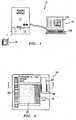
- the container 18includes at least one chamber 20, a reservoir 22, a channel 24 ( FIG. 3 ) connecting the chamber 20 and the reservoir 22, a valve 26 functionally disposed between the reservoir 22 and the chamber 20, and a label 28.
- the chamber 20(see FIG.
- the container 18further includes a plurality of features operable to enable the analysis of the biologic fluid. Some of the features are spatially located within the chamber 20, and each has a coordinate address designating its position. Other features may include reagents disposed within the reservoir 22, or a colorant calibration pad 34, etc.
- the container label 28stores information which is communicated to the apparatus 10 through a label reader 38 ( FIG.4 ).
- the Reader Module 12includes the aforementioned label reader 38, a field illuminator 40, means for determining the volume of a field of the sample, and an image dissector 42.
- the container label reader 38is a mechanism for transferring information from the container 18 of the apparatus 10.
- a practical example of a container label 28is one which is machine readable and one which is capable of communicating information including, but not limited to: 1) the type of analysis(es) to be performed; 2) information concerning the type of features, and the coordinate addresses of those features located within the sample chamber 20; 3) reagent information; 4) lot information; 5) calibration data; etc.
- the label reader 38is a device capable of reading the magnetic strip, the bar code strip, etc.
- the label 28it may be possible to store and extract all of the necessary information from the label 28 itself.
- the label 28may also be a physical feature such as a tab whose position is interpretable by the label reader 38; e.g., Different tab positions relate to different data files.
- the field illuminator 40includes a light source 44, objective optics 46, and preferably a light filtering means 48.
- the light source 44selectively produces light throughout a wavelength range broad enough to be useful for a plurality of analyses (e.g., approximately 340nm to 670nm), from a mechanism such as a fifty watt xenon arc lamp or tungsten halogen lamp, or a pulsatile source of about ten joules.
- Other light sourcesmay be used alternatively and the wavelength range of the light source may vary depending upon the application.
- a light source 44 which selectively produces particular wavelengths of light within the above identified range, or a plurality of light sources 44 each of which produces particular wavelengths within the above identified rangemay be used.
- the objective optics 46include a focusing mechanism 50 for adjusting the position of an objective lens 52 relative to the container 18 (or vice versa).
- the objective lens 52focuses light emanating from the light source 44 into a light beam 54 which, in turn, is directed into the sample quiescently residing within the chamber 20.
- the light beam directed into the sampleis of sufficient area to illuminate at least one imaged field of the sample.
- the sample fieldis defined by the cross-sectional area of the sample image which impinges on the image dissector 42, or a portion thereof, as directed by the objective optics 46 and any intervening field stops.
- the light filtering means 48when included, is used to improve the quality and/or clarity of the desired sample image for a given test or to allow a precise quantitative measurement of light energy emitted from, or passing through, relevant portions of the sample. If the light source 44 is capable of selectively producing particular wavelengths, it may be possible to omit the light filtering means 48.
- a first embodiment of the field illuminator 40utilizes fluorescence to produce an image.
- the first embodimentincludes a flash tube type light source 44, optics 46, and a light filtering means 48 the latter of two which include a first lens 56, a light source excitation filter 58 ("LSE” filter), a light diverting prism 60, a reference detector 62, an objective lens 52, a sample emission filter 66 ("SE” filter), a second lens 67, and a focusing mechanism 50.
- the light diverting prism 60may be a polarizing prism, a dichroic beam splitter, or a half-silvered mirror or prism.
- the first lens 56collects light emanating from the flash tube, or alternate source of illumination, and directs it through the LSE filter 58.
- the LSE filter 58allows light of a predetermined wavelength(s) to pass through (this function can also be described as blocking all but predetermined wavelengths from passing through) and continue on where it strikes the light diverting prism 60. A portion of the light then passes through the light diverting prism 60 and strikes the reference detector 62 positioned adjacent the light diverting prism 60. Feedback from the reference detector 62 allows the filtered excitation light energy to be measured.
- any variations in the excitation light energycan be used to either adjust the intensity of the emission source or to calculate a corrected emission energy.
- Another portion of the light entering the light diverting prism 60is reflected approximately ninety (90) degrees downward through the objective lens 52 and subsequently into the container chamber 20 where the biologic fluid sample quiescently resides.
- the objective lens 52is attached to the focusing mechanism 50 that enables the distance between the objective lens 52 and the chamber 20 to be varied as necessary for focusing purposes.
- a controllable stepper motor arranged to change the focal distance between the objective lens 52 and the container 18is an example of a focusing mechanism 50.
- the objective lens 52is moved relative to the container 18, or vice versa, but alternative methods may be used.
- the wavelengths of light passing through the LSE filter 58 and the objective lens 52subsequently enter the sample, causing material within the sample bearing a chosen colorant to fluoresce and emit light of a particular wavelength. That emitted light passes back through the objective lens 52, through the light diverting prism 60, and then through the SE filter 66.
- the SE filter 66blocks all but (or passes) select wavelengths of light. Those wavelengths of light subsequently pass through the second lens 67 and encounter the image dissector 42.
- the SE filter 66is preferably a tunable liquid crystal display (LCD) filters.
- the LSE filters 58are attached to a first filter wheel 68.
- the first filter wheel 68is synchronized with the light source 44 such that the light source 44 is selectively actuated when the desired LSE filter 58 is positioned in the path of the light beam 54 as described above.
- the SE filters 66are attached to a second filter wheel 70.
- the second filter wheel 70is synchronized with the light source 44 such that the light source 44 is selectively actuated when the desired SE filter 66 is positioned in the path of the light beam 54.
- the first and second filter wheels 68,70 and the light source 44are synchronized such that the light source 44 is selectively actuated when the desired LSE and SE filters 58,66 are positioned in the path of the light beam 54.
- the second embodiment of the field illuminator 40utilizes transmittance to produce an image.
- measurement of the light transmission properties of the sampleis accomplished by positioning a white light source 44 and a first lens 56 under the sample residing within the chamber 20 and directing the light through the chamber first wall 30 (which is transparent in this embodiment), the sample, the chamber second wall 32, the objective lens 52, the SE filter 66, the second lens 67, and thereafter to the image dissector 42.
- the transmittance lightis intermittently energized as transmittance measurements are required.
- the light source 44may be pulsatile, such as from a flash tube, or it may be an incandescent bulb with a means for selectively exposing the sample to the light such as a shutter, or an electronic switch that extinguishes the light entirely.
- the preferred image dissector 42is a charge couple device (CCD) capable of providing at least eight bits of resolution and preferably twelve bits of resolution per pixel.
- CCDcharge couple device
- the image dissector 42converts an image of the light passing through the SE filter 66 into an electronic data format which can be seen and/or interpreted in real-time or at a subsequent time using a data file version of the image.
- the imagecan be interpreted manually by a technician, or with the use of analytical software.
- An image dissector 42 other than a CCDmay be used to convert the image of light into an electronic data format alternatively.
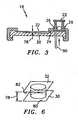
- volumefor volume of the field can mean the volume itself, or can refer to the through-plane thickness 78 of the imaged field because one can be readily determined from the other given the cross-sectional area of the field.
- through-plane thicknessrefers to a line of sight which corresponds to the shortest distance 78 between the interior chamber surface 80 of the first wall 30 and the interior chamber surface 82 of the second wall 32.
- the label reader 38reads the container label 28 which communicates the chamber 20 geometry to the apparatus 10 and with that information the volume of the field can be determined. For example, if the label 28 provides the slope values of the chamber first wall 30 and second wall 32 and a through-plane thickness 78 value, the volume of a field at any position within the chamber 20 can be determined provided the slope values are constant for both walls 30,32 for the entire chamber 20.
- the volumeis determined by sensing the colorant signal from a sample field of unknown volume containing fluid sample having a known colorant concentration.
- the colorant signal magnitude to colorant concentration ratiois communicated to the apparatus 10 through the container label 28 and label reader 38.
- colorantis defined as any reagent that produces a sensible signal by fluorescent emission, or by absorption of light at a specific wavelength, that can be quantified by the apparatus 10.
- the signal magnitude to colorant concentrationmay also be determined by comparison with a second known material such as a pad 34 of material with stable characteristics which is referenced by the apparatus 10 and used to calibrate the response of the colorant.
- the volumeis determined by comparing colorant signal from at least two sample fields.
- the first and second sample fieldscontain colorant of unknown concentration uniformly distributed within the fluid sample.
- the first fieldreferred to here as the calibration field contains a geometric feature of known height or volume. Examples of geometric characteristics include a step, a cavity, or a protuberance of known height or volume within one or both walls, or an object of known volume.
- the volume or height of the geometric characteristicis provided to the Programmable Analyzer 16 through the container label 28 and label reader 38.
- the change in sensible signal due to the displacement of colorant by the known feature in the calibration fieldis measured through the field illuminator 40, and a calibration value of change in sensible signal per volume is calculated by the Programmable Analyzer 16 and stored.
- the Programmable Analyzer 16takes the signal measured from the second field and multiplies it by the signal/volume ratio of the calibration field to arrive at a volume for the second field.
- the volume of the field(s)is determined using interferometric techniques to measure the through-plane thickness.
- the hardware necessary to perform the interferometric techniquesincludes a monochromatic light source and a beamsplitter which operate together to form interference patterns, where the number of observable interference fringes is related to the separation of the chamber walls 30,32.
- the container chamber 30includes specular surfaces on which a virtual reflected image may be detected by the apparatus 10.
- specular surfacesare the two wall surfaces 80,82 in contact with the biologic fluid, or the outer surfaces if the wall thicknesses are known.
- the apparatus 10detects the virtual reflected image on one of the specular surfaces and then refocuses on the virtual reflected image formed on the other specular surface.
- the distance the field illuminator optics 46 moves between the two imagesis the through-plane thickness 78 of the chamber 20 in the particular field.
- a sixth and related embodimentis the use of identifiable patterns on each of the two chamber surfaces 80,82, where these patterns are used as focal targets, as opposed to the virtual images used in the fifth embodiment.
- the Sample Transport Module 14includes a mechanism 84 for transferring biologic fluid sample from the container reservoir 22 to the container chamber 20 and a container positioner 86.
- the mechanism 84includes a valve actuator, for example rod 90, that selectively actuates the container valve 26 to transfer fluid sample from the container reservoir 22 to the container, chamber 20.
- the mechanism 84 for transferring fluid sample from the reservoir to the chambermay be automated or manual and in all cases is sufficient to operate the valve 26, if any, disposed in the container 18.
- the biologic fluid samplemay be placed directly into the container chamber 20 thereby obviating the need for a reservoir 22, a valve 26, and a valve actuator 90.
- the positioner 86is operable to selectively change the position of one of the container 18 or the field illuminator 40 relative to the other of the container 18 or the field illuminator 40, such that all regions of the sample within the chamber 20 can be selectively illuminated and imaged.
- the container 18can be initially located relative to the field illuminator 40 by means of a recognizable feature (e.g. a notch in the container 18), such that once the field illuminator 40 locates the recognizable feature, all other features within the chamber 20 can be accessed by virtue of their coordinate address.
- the positioner 86might include a pair of thumb wheels geared to a tray 87 (or to the field illuminator 40), such that the tray 87 (or the field illuminator 40) can be moved in a plane by rotating the thumb wheels, in a manner similar to that of a microscope stage.
- the positioner 86includes electromechanical actuators 98 for moving the disposable container 18 in the plane (e.g., the x-y plane) relative to the imaged field (or vice versa).
- the actuators 98may be any electromechanical device that can accurately and repeatably position the container 18 and hold that position until directed otherwise.
- the actuators 98may also be capable of moving the container 18 in a manner that causes the sample and reagent to mix within the reservoir 22.
- the Programmable Analyzer 16is described herein as a stand alone device that is in communication with the Reader Module 12 and the Sample Transport Module 14.
- the Programmable Analyzer 16could, alternatively, be packaged with the Reader Module 12 and Sample Transport Module 14 in a single device.
- the Programmable Analyzerincludes a central processing unit (CPU) and hardware connecting the Reader Module 12, Sample Transport Module 14, and the Programmable Analyzer 16 together.
- Software programmed into the CPU(or remotely accessible by the CPU) provides instruction sets, hereinafter referred to as analysis algorithms, that detail all the steps necessary to perform a variety of analyses. Simplistic instructions sets may alternatively be provided directly to the Programmable Analyzer 16 through the container label 28 and label reader 38.
- the Programmable Analyzer 16preferably further includes a keyboard/keypad type input device 100 and a monitor type display device 102. A variety of acceptable keyboards/keypads and monitors are commercially available and therefore will not be described further.
- the CPUis programmed to control the Reader Module 12 and the Sample Transport Module 14, directing them to perform tasks according to the analysis algorithm at hand.
- the CPUis also programmed to receive and manipulate the electronic data format, of the fluid sample image (referred to hereinafter generally as "data") produced by the image dissector 42.
- the analysis algorithms and/or input from the operator and/or container label 28provide the instructions for manipulating the data into a useful output.
- the CPU's programmingreflects the apparatus's 10 level of automation. In the case of the simplistic embodiment of the positioner 86, no positioner programming is provided because manually operated thumb wheels are used in lieu of automation. Likewise, the mechanism 84 for transferring biologic sample from the container reservoir 22 to the container chamber 20 may also be manually operated. In an automated embodiment, programming stored within the CPU or remotely accessed by the CPU (and/or input from the keyboard 100) enables the CPU, for example, to control the label reader 38 to extract information from the container label 28, to transfer biologic sample from the container reservoir 22 to the container chamber 20, and to control movement of the container 18 relative to the Reader Module 12 (or vice versa).
- the algorithmsare constructed to utilize the features of the container 18 as well as the capabilities of the apparatus 10 such as the Reader Module's 12 ability to determine the volume of one or more select sample fields and the Sample Transport Module's 14 ability to move the container 18 to permit access to any sample field.
- the Container label 28is read thereby providing the Programmable Analyzer 16 sufficient information to determine what test(s) is requested and the information necessary to perform that test.
- the Programmable Analyzer 16is programmed to use the label information to access the appropriate analysis algorithm and in some instances data files stored within the Analyzer 16 (or stored remotely) as well.
- the analysis algorithmprovides the step by step instructions necessary to direct the Sample Transport Module 14 and the Reader Module 12, and any other functions necessary in the performance of the test.
- the instructionsmay direct the Reader Module 12 to actuate the container valve 26 thereby transferring the fluid sample from the reservoir 22 to the chamber 20. For those analyses that are timed, the valve actuation may be used to initiate the time period
- the Reader Module 12may also be used to visually monitor the chamber 20 to determine if or when an optimum quantity of sample has reached the chamber 20.
- the instructionscan also direct the Reader Module 12, based on information provided through the container label 28, to use particular filters 58,66 appropriate for particular wavelengths, or to move the container 18 to particular positions to provide the Reader Module 12 access to particular fields, etc.
- the analytical algorithm identified through the label 28will call for the measurements necessary to determine the optical density of the field.
- the concentration of the analyatecan subsequently be calculated by the Programmable Analyzer 16 using an analysis algorithm which uses calibration data communicated through the container label 28.
- an analysis algorithmmay direct that a field be searched for images of a particular cell type for enumeration or evaluation purposes.
- the algorithmmay direct that the a single, most optimal field be considered, or most preferably that multiple fields be considered and the results be statistically analyzed to obtain a final statistically acceptable result.
- the volume of the sample fieldmay be determined, if required for the analysis, and that data used in the final results calculation.
- the considerable utility of the apparatus 10enables a wide variety of analyses to be performed of a single sample, using a single analytical container 18.
- the detailed examples given beloware offered so that a complete appreciation of the present invention apparatus may be gained.
- a container 18 having approximately 0.8 micrograms (pg) of a sensible colorant and 50 ⁇ l of anticoagulated whole blood disposed within its reservoir 22is inserted into the Sample Transport Module 14. Prior to insertion, the operator may gently shake the container 18 to ensure uniform mixing of the colorant and the fluid sample.
- the label reader 38 disposed within the Reader Module 14reads the container label 28 and transfers the information contained within the label 28 to the Programmable Analyzer 16. In this example, the information identifies one or more specific analysis algorithms to be used and a plurality of container features operable to enable the analysis of the biologic fluid sample.
- Those featuresinclude identifying the anticoagulating agent as EDTA, the sensible colorant as a fluorescent highlighting supravital stain such as acridine orange (or basic orange-21 or the like), and physical characteristics of the container chamber 20 and the coordinate addresses of those physical characteristics within the chamber 20.
- the second wall 32 of the container chamber 20need be transparent since a fluorescent stain is being used.
- the Programmable Analyzer 16next directs the rod 90 within the Reader Module 12 to actuate the valve 26 within the container 18 and thereby release the sample and colorant mixture into the chamber 20.
- the sampleOnce the sample is distributed within the chamber 20, the sample resides quiescently.
- the only sample motion within the chamber 20will possibly be Brownian motion of the sample's formed constituents, and that motion is non-disabling for the present invention.
- the analysis algorithmuses the positioner 86 to move the container 18 to a position where the field illuminator 40 is aligned with a first region of the chamber 20, and in particular with one of a plurality of fields having a through-plane thickness 78 of approximately twenty microns.
- the coordinate address of each of these fieldsis known and communicated to the Programmable Analyzer 16 through the label 28.
- the chamber through-plane thickness 78 of approximately twenty micronsis chosen for a couple of reasons.
- an evaluation volume of 0.02 ⁇ l,(formed by a particular sample field having a cross-sectional area of one millimeter (mm) and a through-plane thickness 78 of twenty microns) typically contains 50-200 WBC's which is a favorable quantity for evaluative purposes.
- the cross-sectional area referred tois the area of the sample imaged by the field illuminator 40 as described above.
- a through-plane thickness 78 of twenty micronsprovides an optimal chamber 20 for rouleaux and lacunae formation.
- the samplewill appear opaque when examined with the epi-illuminated fluorescence and will not be favorable for analysis.
- the opaque appearanceis caused by the red blood cells (RBC's), which form an overlapping mass prior to the formation of the rouleaux.
- the analysis algorithm stored within the Programmable Analyzer 16provides a timing function wherein operation of the field illuminator 40 is delayed for a period of approximately thirty (30) seconds after the sample has been introduced into the chamber 20. During that time, the Programmable Analyzer 16 may position the appropriate SE or LSE filters 58,66 if any, within the path of the light beam 54 within the field illuminator 40.
- light selectively produced from the light source 44 and filtered within the field illuminator 40is directed into a sample field within the chamber 20.
- the light passing into the samplecauses the colorant within the sample to fluoresce and emit light of a particular wavelength.
- the emitted lightthen passes through the field illuminator 40 and into the image dissector 42 where it is converted into an electronic format in real time.
- the electronic format of the emitted imagewhich can be shown real-time on the monitor 102, will show that after lying substantially motionless for approximately thirty (30) seconds within the chamber 20, the RBC's will have spontaneously clustered into a plurality of rouleaux separated by lacunae. It is in the lacunae where whole blood sample constituents other than RBC's (e.g., WBC's and platelets) can be found and evaluated. Using 0.02 ⁇ l sample fields keeps the number of WBC's in each field reasonable (a normal whole blood sample contains approximately 7,000 WBC's per ⁇ l of sample; a 0.02 ⁇ l sample of normal whole blood contains approximately 140 WBC's). A number of fields within the first region are evaluated until a statistically sufficient number of cells are counted, which in practice is approximately 1000 cells.
- whole blood sample constituentse.g., WBC's and platelets
- the Programmable Analyzer 16directs the Reader Module 12 to perform the evaluation process again, this time in a second region of the chamber 20 having a plurality of fields with a through-plane thickness 78 slightly larger than twenty microns.
- the larger volume of the fields within the second regionare more apt to have a sample with a statistically acceptable population of WBC's.
- the Programmable Analyzer 16directs the Reader Module 12 to perform the evaluation process again, this time in a third region of the chamber 20 having a plurality of fields with a through-plane thickness 78 slightly smaller than twenty microns and consequent lesser volume.
- the coordinate addresses of the fields in either regionare known and communicated to the Programmable Analyzer 16 through the label 28.
- the WBC'scan be analyzed within the sample using the image dissector 42 of the Reader Module 12, for example, alone or with analysis software. A differential count could be determined from the data collected.
- a complete blood countrequires that the RBC's be evaluated for hemoglobin content using a chemical analysis.
- the operatordeposits the whole blood sample into the container reservoir 22 and gently shakes the container 18 to ensure uniform mixing of the sample and a colorant previously deposited in the reservoir 22, and inserts the container 18 into the Reader Module 12.
- the label reader 38reads the container label 28 and transfers the information contained within the label 28 to the Programmable Analyzer 16. Similar to the process described above, the label provided information identifies a plurality of analysis algorithms and a plurality of container features operable to enable the analysis of the biologic fluid sample.
- the container featuresinclude lysing and stabilizing reagents and their position within a chamber 20, the colorant deposited in the reservoir, and physical characteristics of the chamber 20.
- the container 18includes a first chamber and a second chamber, both in fluid communication with the reservoir 22.
- the hemoglobin evaluationis performed in the first chamber and the remainder of the complete blood count tests are performed in the second chamber.
- all of the tests necessary for the complete blood count, including the hemoglobin evaluationare done in a single chamber 20.
- the lysing reagentis used to break down RBC's within the sample and thereby release the hemoglobin stored within the RBC's.
- the stabilizer reagentis used to increase the reliability of the hemoglobin evaluation.
- the Programmable Analyzer 16directs the rod 90 to actuate the container valve 26 and thereby release the sample and colorant mixture into the first chamber.
- the analysis algorithm stored within the Programmable Analyzer 16starts an internal timer, and the hemoglobin analysis is performed after one or more predetermined intervals of time.
- the analysis algorithm for the hemoglobin evaluationoperates in a manner similar to that described above in the hematology example where the Programmable Analyzer 16 positions the appropriate SE or LSE filters 58,66 if any, within the path of the light beam 54 within the field illuminator 40, and light beam 54 selectively produced from the light source 44 and filtered within the field illuminator 40 is directed into the sample quiescently residing within the first chamber forming a field having an imaged area, etc.
- the light emitted from the colorant within the samplepasses back through the field illuminator 40 and into the image dissector 42 where it is converted into an electronic format in real time, and the optical density of the hemoglobin in the first chamber is measured and the hemoglobin concentration is calculated.
- the remaining analyses associated with a complete blood countare performed in the second chamber.
- the portion of the biologic fluid sample used for the hemoglobin evaluationis contiguous with remaining portion of the fluid sample.
- the fluid sample ponion devoted to the hemoglobin evaluationis preferably oriented toward one side of the chamber 20, however, to minimize potential mixing of the lysing agent with the remaining portion of the fluid sample.
- the coordinate addresses of the hemoglobin evaluation reagents and the chamber region where the evaluation is best performedare communicated to the Programmable Analyzer 16 via the label 28.
- the chamber through-plane thickness 78 in the hemoglobin evaluation regionis small enough such that vertical diffusion (and ultimate equilibrium) of the chemical reagents within the biologic fluid sample occurs at a much faster rate than lateral diffusion, thereby preventing the lateral diffusion of the reagent and possible interferences with the analyses to be performed.
- a complete urinalysisrequires a chemical analysis and a particulate analysis of the urine sample.
- the operatorplaces a urine sample within the reservoir 22 of the container 18 and the container 18 is installed within the Reader Module 12.
- the label reader 38reads the container label 28 and transfers the information contained therein to the Programmable Analyzer 16.
- the information from the label 28identifies a plurality of analysis algorithms and container features operable to enable the analysis of the biologic fluid sample, and like the hemoglobin example above, the analyses may be performed in a single chamber 20 or in a plurality of chambers.
- the label 28provides information that the container features include colorant disposed in the container reservoir 22, one or more chemical reagents disposed at particular coordinate addresses within a chamber 20 to colorometrically relate information concerning the specific gravity, pH, glucose, and ketones within the urine sample after a given period of time, and physical characteristics of the chamber 20 that enable detection, evaluation, and/or enumeration of particles within the urine sample.
- the physical characteristics of the chamber 20may, for example, be similar to those described above for the evaluation of WBC's where a plurality of regions of different through-plane thickness 78 may be accessed iteratively to provide optimum results.
- the Programmable Analyzer 16directs the rod 90 within the Reader Module 12 to actuate the valve 26 within the container 18 and thereby release the sample and colorant mixture into the chamber(s) 20.
- the analysis algorithm stored within the Programmable Analyzer 16starts an internal timer when the sample is released into the chamber(s) 20, and the chemical analysis is performed at some time thereafter.
- the Programmable Analyzer 16positions the appropriate SE or LSE filters 58,66, if any, within the path of the light beam 54 within the field illuminator 40, and the light beam 54 selectively produced from the light source 44 and filtered within the field illuminator 40 is directed into a sample field quiescently residing within the chamber 20.
- the light emitted from the colorant within the samplepasses back through the field illuminator 40 and into the image dissector 42 where it is converted into an electronic format in real time.
- the remaining analyses associated with a urinalysismay be performed in a second chamber or in a contiguous region of the same chamber 20.
- the best mode of the apparatus 10is described as being used with a particular sample container 18.
- Alternative containersmay be used with the present invention apparatus.
- the field illuminatoris described as having a light diverting prism 60 and a plurality of lens' 52, 56, and 67. Different filter positions, or no filters at all, may increase or eliminate the need for certain light diverting prisms and lens'.
Landscapes
- Health & Medical Sciences (AREA)
- Life Sciences & Earth Sciences (AREA)
- Chemical & Material Sciences (AREA)
- Engineering & Computer Science (AREA)
- Immunology (AREA)
- Hematology (AREA)
- General Physics & Mathematics (AREA)
- Pathology (AREA)
- General Health & Medical Sciences (AREA)
- Biochemistry (AREA)
- Analytical Chemistry (AREA)
- Physics & Mathematics (AREA)
- Biomedical Technology (AREA)
- Urology & Nephrology (AREA)
- Molecular Biology (AREA)
- Dispersion Chemistry (AREA)
- Medicinal Chemistry (AREA)
- Biotechnology (AREA)
- Microbiology (AREA)
- Food Science & Technology (AREA)
- Cell Biology (AREA)
- Signal Processing (AREA)
- Investigating, Analyzing Materials By Fluorescence Or Luminescence (AREA)
- Investigating Or Analysing Biological Materials (AREA)
- Investigating Or Analysing Materials By Optical Means (AREA)
Abstract
Description
- The present invention relates to apparatus for analyzing biologic fluid samples in general, and to apparatus capable of performing analyses in a variety of disciplines including hematology, biologic chemistry, immunochemistry, serology, immunology, and urinalysis in particular.
- Historically, biologic fluid samples such as whole blood, urine, cerebrospinal fluid, body cavity fluids, etc. have had their particulate or cellular contents evaluated by smearing a small undiluted amount of the fluid on a slide and evaluating that smear under a microscope. Reasonable results can be gained from such a smear, but the accuracy and reliability of the data depends largely on the technician's experience and technique. In addition, although biologic fluid sample smears are widely used for evaluation purposes, their labor intensive natures makes them generally not favored for commercial applications.
- Another known method for evaluating a biologic fluid sample involves diluting a volume of the sample, placing it within a chamber, and manually evaluating and enumerating the constituents within the diluted sample. Dilution is necessary if there is a high concentration of constituents within the sample, and for routine blood counts several different dilutions may be required because it is impractical to have counting chambers or apparatus which can examine variable volumes as a means to compensate for the disparities in constituent populations within the sample. In a sample of whole blood from a typical individual, for example, there are about 4.5 x 10⁶ red blood cells (RBC's) per microliter (µl) of blood sample, but only about 0.25 x 10⁶ of platelets and 0.007 x 10⁶ white blood cells (WBC's) per µl of blood sample. To determine a WBC count, the whole blood sample must be diluted within a range of about one part blood to twenty pans diluent (1:20) up to a dilution of approximately 1:256 depending upon the exact dilution technique used, and it is also generally necessary to selectively lyse the RBC's with one or more reagents. Lysing the RBC's effectively removes them from view so that the WBC's can be seen. To determine a platelet count, the blood sample must be diluted within a range of 1:100 to about 1:50,000. Platelet counts do not, however, require a lysis of the RBC's in the sample. A disadvantage of evaluating a whole blood sample in this manner is that the dilution process is time consuming and expensive. In addition, adding diluents to the whole blood sample increases the error probability within the sample data. Adding diluents also increases the quantity of waste material that must be disposed of upon completion of the test.
- A modem method for evaluating a biologic fluid sample is impedance or optical flow cytometry. Flow cytometry involves circulating a diluted fluid sample through one or more small diameter orifices, each employing an impedance type or an optical type sensor which evaluates the constituents as they pass through the orifice in single file. Using the example of whole blood again, the sample must be diluted to mitigate the overwhelming number of the RBC's relative to the WBC's and platelets, and to provide adequate cell-to-cell spacing so that individual cells may be analyzed. Although more expedient and consistent than the above described methods, flow cytometers also possess numerous disadvantages. Some of those disadvantages stem from the plumbing required to carry the sample to, and the fluid controls necessary to control the fluid flow rate through, the sensor means. The precise control of this flow is essential to the cytometer's accurate operation. The plumbing within flow cytometers can and often does leak, potentially compromising the accuracy and the safety of the equipment. The fluid flow controls and dilution equipment require periodic recalibration. In fact, the need for recalibration illustrates the potential for inaccurate results and the undesirable operating costs that exist with many presently available hematology analyzers which use flow cytometers and/or impedance orifices. The volume of reagents required to satisfy large dilution ratios increases the operating cost initially by virtue of the reagent purchase price and subsequently because of the additional waste disposal costs.
- Another modern method for evaluating biologic fluid samples is one that focuses on evaluating specific subtypes of WBC's. This method utilizes a cuvette having an internal chamber about 25 microns thick with one transparent panel. A laser beam of light passing through the transparent panel scans the cuvette for WBC's. Reagents added to the sample cause each WBC to fluoresce when excited by the laser beam. The fluorescing of the particular WBC's provides an indication that particular types of WBC's are present. Because the red blood cells form a partly obscuring layer in this method, they cannot themselves be enumerated or otherwise evaluated, nor can the platelets.
- There are a multitude of methods for determining the presence of soluble constituents, such as chemical components, antibodies, etc., within a sample of biologic fluid such as urine, plasma, or serum. Most of the methods require dilution of the sample and the addition of one or more reagents to the sample. Other methods require a small, but carefully metered drop of biologic fluid sample be added to a piece of reactive film. Different analytical instruments are usually required for each method of analysis, and those instruments are expensive not only in terms of initial capital cost but also in terms of the maintenance over the life of the various instruments, and the operator training necessary to properly staff the various instruments. The operator function can vary considerably from instrument to instrument, thereby increasing the complexity of the operator training and the potential for operator error. To date, because of the widely differing requirements of the various tests, there is not a single instrument platform which will perform cross-discipline tests, most especially tests of hematology, which require particle analysis, and tests of chemistry/immunochemistry or serology, which require quantitative light analysis.
- What is needed is a method and an apparatus for evaluating a sample of substantially undiluted biologic fluid, one capable of providing accurate results, one that does not use a significant volume of reagent (s), one that does not require sample fluid flow during evaluation, one that can perform particulate component and chemical component analyses, and one that is cost-effective.
- Document
US-5646046 discloses an instrument for automatically performing analysis relating to thrombosis and hemostasis. US-5547849 discloses an apparatus and method for volumetric capillary cytometry.US-4171866 describes a disposable volumetric slide.- It is, therefore, an object of the present invention to provide an apparatus for analyzing biologic fluid samples that has the capacity to provide analytical data for a variety of disciplines including, but not limited to, hematology, biologic chemistry, immunochemistry, serology, immunology, urinalysis, immunoassay, antibiotic sensitivity, and bacterial growth.
- It is another object of the present invention to provide a single apparatus for analyzing biologic fluid samples that has the capacity to perform a greater number of tests than can be done on any single presently available device.
- It is another object of the present invention to provide an apparatus for analyzing biologic fluid samples that uses a quiescent sample, and thereby avoids the problems associated with devices utilizing fluid flow, particularly those utilizing fluid flow outside the sample chamber and those utilizing fluid flow during the analysis process.
- It is another object of the present invention to provide an apparatus for analyzing biologic fluid samples that has the capacity to search a biologic fluid sample for an optimum region to perform a given test.
- It is another object of the present invention to provide an apparatus for analyzing biologic fluid samples that has the capacity to determine the volume of a given sample field in a fluid sample chamber.
- According to a first aspect of the present invention, there is provided an apparatus for testing a sample of biologic fluid quiescently residing within a chamber. According to a second aspect of the invention, there is provided a method for testing a sample of biologic fluid as claimed in
claim 24. The apparatus may include a light source, a positioner, a means for determining the volume of a sample field, and an image dissector. The light source is operable to illuminate a sample field of known, or ascertainable, area. The positioner is operable to selectively change the position of one of the chamber or the light source relative to the other, thereby permitting selective illumination of all regions of the sample. The means for determining the volume of a sample field can determine the volume of a sample field illuminated by the light source. The image dissector is operable to convert an image of light passing through or emanating from the sample field into an electronic data format. - An advantage of the present invention is that the present invention apparatus for analyzing a sample of biologic fluid is substantially more versatile than any presently available apparatus capable of analyzing biologic fluid. For example, the present invention has utility in numerous fields including, but not limited to, hematology, biologic chemistry, immunochemistry, serology, immunology, urinalysis, immunoassays, antibiotic sensitivity, and bacterial growth. From an equipment standpoint, this versatility will give many medical offices and laboratories analytical capability that was realistically unavailable heretofore because of cost, space, manpower, training, etc. When testing a blood sample for anemia, for example, it is common to analyze the sample using hematological tests such as hemoglobin, hematocrit, and reticulocyte count, and also to analyze the sample using chemical tests to establish the presence and quantity of iron or ferritin and immunochemical tests such as B-12 and folate. Using presently available devices, the medical office or laboratory would typically rely on an impedance counter or flow system to determine the hematological parameters and a chemical analyzer or immunochemistry system to determine the other analytical parameters, any of which may not be readily available to the office or laboratory. The present invention apparatus, in contrast, can perform all of these tests. For those medical offices and laboratories that presently do have multiple discipline analysis capability, the present invention will substantially reduce equipment cost, space required, manpower and training.
- The present invention can also, in most instances, increase the number of tests possible on one analysis device in a particular field. In the field of hematology, for example, the present invention can be programmed to perform analyses such as hematocrit and hemoglobin evaluation, white blood cell count, platelet count, red blood cell indices, red blood cell morphology, five-part differential, reticulocytes evaluation, white blood cell subset analyses, sedimentation rate (ESR), and sepsis detection. As far as is known, no single presently available analysis device can perform all of these analyses.
- Another advantage of the present invention apparatus for analyzing a biologic sample is that it does not require substantial dilution or complex fluid handling apparatus.
- As stated in the Background of the Invention, analyzing whole blood in an impedance or optical flow cytometer has several drawbacks relating to the amount the sample must be diluted and the internal plumbing of the device. The present invention apparatus, on the other hand, requires relatively little or no dilution of the biologic sample, has no internal plumbing, and does not require external calibration. A person of skill in the art will recognize that it is a significant advantage to provide an apparatus with increased reliability. Specifically, the present invention's lack of plumbing eliminates the possibility of downtime attributable to plumbing leaks or that due to a sensor being miscalibrated. The present invention also avoids the expensive service contracts associated with many flow cytometers. Perhaps most importantly, the lack of need for any external calibration removes a large source of potential errors and considerable operational complexity.
- Another advantage of the present invention apparatus for analyzing a biologic sample is that it provides faster results for a complete set of tests. In many cases, faster test results mean better patient care because a patient may be evaluated with the results of the tests in hand, rather than the current practice of releasing the patient and requiring a repeat visit if unusual results are encountered. Faster test results also enable the medical office or laboratory to process more test samples in a given period of time, thereby increasing the number of patients which can helped and the revenue stream that emanates therefrom.
- Another advantage of the present invention is its ability to search a biologic fluid sample for an optimum region(s) to perform a given test. One of the problems common to analyzing biologic samples is that the concentration of constituents within the sample can vary dramatically. Presently available analysis apparatus accounts for the spectrum of constituent concentrations by performing several test iterations. For example if the constituent population within a particular sample is too great, a second iteration of sample must be created by dilution to decrease the number of constituents in a given volume, or vice-versa. This dilution process increases the analysis time and cost, and the probability of error in the analysis. The present invention, in contrast, avoids multiple dilutions by using a biologic fluid container which can segregate constituents and the concentrations of constituents within a chamber, and by having means to know which constituents are where and in what concentration within the chamber for a given analysis. In addition, the present invention is capable of evaluating regions within the sample containing chamber comparatively to find a sample region having optimum characteristics for the test(s) at hand. In those situations where it is desirable to evaluate the sample statistically, the present invention can be programmed to evaluate a plurality of regions containing acceptable characteristics and that data collectively analyzed.
- Another advantage of the present invention is that it provides a safe means to handle biologic samples. The present invention apparatus includes means for safely handling biologic fluid samples during analysis. Risks associated with handling and disposing of biologic fluid samples are consequently minimized.
- These and other objects, features and advantages of the present invention will become apparent in light of the detailed description of the best mode embodiment thereof, as illustrated in the accompanying drawings.
FIG. 1 is a diagrammatic view of the present invention apparatus for analyzing a sample of biologic fluid quiescently residing within a chamber.FIG. 2 is a diagrammatic view of a container for holding a biologic fluid sample for analysis.FIG. 3 is a cross-sectional view of the container shown inFIG. 2 .FIG. 4 is a diagrammatic view of an embodiment of the present invention Reader Module which utilizes fluorescence to produce an image.FIG. 5 is a diagrammatic view of another embodiment of the present invention Reader Module which utilizes fluorescence to produce an image.FIG. 6 is a diagrammatic illustration of a sample field between a first chamber wall and a second chamber wall.- Referring to
FIGS. 1 and 2 , theapparatus 10 for analyzing a sample of biologic fluid quiescently residing within a chamber includes aReader Module 12, aSample Transport Module 14, and aProgrammable Analyzer 16. For purposes of this disclosure the terms "analyze" and "analysis" shall be defined as any examination or evaluation of the fluid sample, including but not limited to, the examination of constituents within the sample. Thepresent invention apparatus 10 is preferably used with aparticular container 18 for holding a biologic fluid sample for analysis. Briefly describe, thecontainer 18 includes at least onechamber 20, areservoir 22, a channel 24 (FIG. 3 ) connecting thechamber 20 and thereservoir 22, avalve 26 functionally disposed between thereservoir 22 and thechamber 20, and alabel 28. The chamber 20 (seeFIG. 3 ) includes afirst wall 30 and a transparentsecond wall 32. In some embodiments, thefirst wall 30 is also transparent. Fluid sample residing within thechamber 20 may be imaged through one or bothtransparent walls container 18 further includes a plurality of features operable to enable the analysis of the biologic fluid. Some of the features are spatially located within thechamber 20, and each has a coordinate address designating its position. Other features may include reagents disposed within thereservoir 22, or acolorant calibration pad 34, etc. Thecontainer label 28 stores information which is communicated to theapparatus 10 through a label reader 38 (FIG.4 ). - Referring to
FIGS. 4 and5 , theReader Module 12 includes theaforementioned label reader 38, afield illuminator 40, means for determining the volume of a field of the sample, and animage dissector 42. Thecontainer label reader 38 is a mechanism for transferring information from thecontainer 18 of theapparatus 10. A practical example of acontainer label 28 is one which is machine readable and one which is capable of communicating information including, but not limited to: 1) the type of analysis(es) to be performed; 2) information concerning the type of features, and the coordinate addresses of those features located within thesample chamber 20; 3) reagent information; 4) lot information; 5) calibration data; etc. If, for example, thelabel 28 is a magnetic strip or a bar code strip, then thelabel reader 38 is a device capable of reading the magnetic strip, the bar code strip, etc. In some instances, it may be possible to store and extract all of the necessary information from thelabel 28 itself. In other instances where the quantity of information to be communicated is considerable, however, it may be more practical to have thelabel 28 direct theapparatus 10 to a data file stored within theProgrammable Analyzer 16 or stored remotely that contains all the appropriate information. Remotely stored data files can be accessed via modern, dedicated telecommunications line, the internet, wide area network, or other telecommunication means. Thelabel 28 may also be a physical feature such as a tab whose position is interpretable by thelabel reader 38; e.g., Different tab positions relate to different data files. - The
field illuminator 40 includes alight source 44,objective optics 46, and preferably a light filtering means 48. Thelight source 44 selectively produces light throughout a wavelength range broad enough to be useful for a plurality of analyses (e.g., approximately 340nm to 670nm), from a mechanism such as a fifty watt xenon arc lamp or tungsten halogen lamp, or a pulsatile source of about ten joules. Other light sources may be used alternatively and the wavelength range of the light source may vary depending upon the application. Alternatively, alight source 44 which selectively produces particular wavelengths of light within the above identified range, or a plurality oflight sources 44 each of which produces particular wavelengths within the above identified range, may be used. Theobjective optics 46 include a focusingmechanism 50 for adjusting the position of anobjective lens 52 relative to the container 18 (or vice versa). Theobjective lens 52 focuses light emanating from thelight source 44 into alight beam 54 which, in turn, is directed into the sample quiescently residing within thechamber 20. The light beam directed into the sample is of sufficient area to illuminate at least one imaged field of the sample. The sample field is defined by the cross-sectional area of the sample image which impinges on theimage dissector 42, or a portion thereof, as directed by theobjective optics 46 and any intervening field stops. The light filtering means 48, when included, is used to improve the quality and/or clarity of the desired sample image for a given test or to allow a precise quantitative measurement of light energy emitted from, or passing through, relevant portions of the sample. If thelight source 44 is capable of selectively producing particular wavelengths, it may be possible to omit the light filtering means 48. - The preferred embodiment of the
field illuminator 40 varies depend upon the principle used to produce the image. Referring toFIG.4 , a first embodiment of thefield illuminator 40 utilizes fluorescence to produce an image. The first embodiment includes a flash tubetype light source 44,optics 46, and a light filtering means 48 the latter of two which include afirst lens 56, a light source excitation filter 58 ("LSE" filter), alight diverting prism 60, areference detector 62, anobjective lens 52, a sample emission filter 66 ("SE" filter), asecond lens 67, and a focusingmechanism 50. Thelight diverting prism 60 may be a polarizing prism, a dichroic beam splitter, or a half-silvered mirror or prism. Thefirst lens 56 collects light emanating from the flash tube, or alternate source of illumination, and directs it through theLSE filter 58. TheLSE filter 58 allows light of a predetermined wavelength(s) to pass through (this function can also be described as blocking all but predetermined wavelengths from passing through) and continue on where it strikes thelight diverting prism 60. A portion of the light then passes through thelight diverting prism 60 and strikes thereference detector 62 positioned adjacent thelight diverting prism 60. Feedback from thereference detector 62 allows the filtered excitation light energy to be measured. Since fluorescence emission is directly proportional to the energy of the fluorescence excitation, any variations in the excitation light energy, as measured by thereference detector 62, can be used to either adjust the intensity of the emission source or to calculate a corrected emission energy. Another portion of the light entering thelight diverting prism 60 is reflected approximately ninety (90) degrees downward through theobjective lens 52 and subsequently into thecontainer chamber 20 where the biologic fluid sample quiescently resides. Theobjective lens 52 is attached to the focusingmechanism 50 that enables the distance between theobjective lens 52 and thechamber 20 to be varied as necessary for focusing purposes. A controllable stepper motor arranged to change the focal distance between theobjective lens 52 and thecontainer 18 is an example of a focusingmechanism 50. Typically, theobjective lens 52 is moved relative to thecontainer 18, or vice versa, but alternative methods may be used. The wavelengths of light passing through theLSE filter 58 and theobjective lens 52 subsequently enter the sample, causing material within the sample bearing a chosen colorant to fluoresce and emit light of a particular wavelength. That emitted light passes back through theobjective lens 52, through thelight diverting prism 60, and then through theSE filter 66. The SE filter 66 blocks all but (or passes) select wavelengths of light. Those wavelengths of light subsequently pass through thesecond lens 67 and encounter theimage dissector 42. TheSE filter 66 is preferably a tunable liquid crystal display (LCD) filters. - If there is more than one
LSE filter 58, the LSE filters 58 are attached to afirst filter wheel 68. Thefirst filter wheel 68 is synchronized with thelight source 44 such that thelight source 44 is selectively actuated when the desiredLSE filter 58 is positioned in the path of thelight beam 54 as described above. Likewise, if there is more than oneSE filter 66, the SE filters 66 are attached to asecond filter wheel 70. Thesecond filter wheel 70 is synchronized with thelight source 44 such that thelight source 44 is selectively actuated when the desiredSE filter 66 is positioned in the path of thelight beam 54. If there is more than oneLSE filter 58 and more than oneSE filter 66, then the first andsecond filter wheels light source 44 are synchronized such that thelight source 44 is selectively actuated when the desired LSE and SE filters 58,66 are positioned in the path of thelight beam 54. - Referring to
FIG.5 , the second embodiment of thefield illuminator 40 utilizes transmittance to produce an image. In the second embodiment of thefield illuminator 40, measurement of the light transmission properties of the sample is accomplished by positioning awhite light source 44 and afirst lens 56 under the sample residing within thechamber 20 and directing the light through the chamber first wall 30 (which is transparent in this embodiment), the sample, the chambersecond wall 32, theobjective lens 52, theSE filter 66, thesecond lens 67, and thereafter to theimage dissector 42. The transmittance light is intermittently energized as transmittance measurements are required. Thelight source 44 may be pulsatile, such as from a flash tube, or it may be an incandescent bulb with a means for selectively exposing the sample to the light such as a shutter, or an electronic switch that extinguishes the light entirely. - The
preferred image dissector 42 is a charge couple device (CCD) capable of providing at least eight bits of resolution and preferably twelve bits of resolution per pixel. Theimage dissector 42 converts an image of the light passing through theSE filter 66 into an electronic data format which can be seen and/or interpreted in real-time or at a subsequent time using a data file version of the image. The image can be interpreted manually by a technician, or with the use of analytical software. Animage dissector 42 other than a CCD may be used to convert the image of light into an electronic data format alternatively. - Referring to
FIG.6 , as used herein the term "volume" for volume of the field can mean the volume itself, or can refer to the through-plane thickness 78 of the imaged field because one can be readily determined from the other given the cross-sectional area of the field. As used herein, the term "through-plane thickness" refers to a line of sight which corresponds to theshortest distance 78 between theinterior chamber surface 80 of thefirst wall 30 and theinterior chamber surface 82 of thesecond wall 32. - Referring to
FIGS. 3 and4 , in a first embodiment of the means for determining the volume of one or more fields within the sample, thelabel reader 38 reads thecontainer label 28 which communicates thechamber 20 geometry to theapparatus 10 and with that information the volume of the field can be determined. For example, if thelabel 28 provides the slope values of the chamberfirst wall 30 andsecond wall 32 and a through-plane thickness 78 value, the volume of a field at any position within thechamber 20 can be determined provided the slope values are constant for bothwalls entire chamber 20. - In a second embodiment of the means for determining the volume of one or more select fields within the sample, the volume is determined by sensing the colorant signal from a sample field of unknown volume containing fluid sample having a known colorant concentration. The colorant signal magnitude to colorant concentration ratio is communicated to the
apparatus 10 through thecontainer label 28 andlabel reader 38. As used within this specification, the term colorant is defined as any reagent that produces a sensible signal by fluorescent emission, or by absorption of light at a specific wavelength, that can be quantified by theapparatus 10. The signal magnitude to colorant concentration may also be determined by comparison with a second known material such as apad 34 of material with stable characteristics which is referenced by theapparatus 10 and used to calibrate the response of the colorant. - In a third embodiment of the means for determining the volume of one or more select fields, the volume is determined by comparing colorant signal from at least two sample fields. The first and second sample fields contain colorant of unknown concentration uniformly distributed within the fluid sample. The first field, referred to here as the calibration field contains a geometric feature of known height or volume. Examples of geometric characteristics include a step, a cavity, or a protuberance of known height or volume within one or both walls, or an object of known volume. The volume or height of the geometric characteristic is provided to the
Programmable Analyzer 16 through thecontainer label 28 andlabel reader 38. The change in sensible signal due to the displacement of colorant by the known feature in the calibration field is measured through thefield illuminator 40, and a calibration value of change in sensible signal per volume is calculated by theProgrammable Analyzer 16 and stored. To determine the volume of the second, or unknown field, theProgrammable Analyzer 16 takes the signal measured from the second field and multiplies it by the signal/volume ratio of the calibration field to arrive at a volume for the second field. - In a fourth embodiment of the means for determining the volume of one or more select fields, the volume of the field(s) is determined using interferometric techniques to measure the through-plane thickness. The hardware necessary to perform the interferometric techniques includes a monochromatic light source and a beamsplitter which operate together to form interference patterns, where the number of observable interference fringes is related to the separation of the
chamber walls - In a fifth embodiment of the means for determining the volume of one or more select fields, the
container chamber 30 includes specular surfaces on which a virtual reflected image may be detected by theapparatus 10. The specular surfaces are the twowall surfaces apparatus 10 detects the virtual reflected image on one of the specular surfaces and then refocuses on the virtual reflected image formed on the other specular surface. The distance thefield illuminator optics 46 moves between the two images is the through-plane thickness 78 of thechamber 20 in the particular field. A sixth and related embodiment is the use of identifiable patterns on each of the two chamber surfaces 80,82, where these patterns are used as focal targets, as opposed to the virtual images used in the fifth embodiment. - The
Sample Transport Module 14 includes amechanism 84 for transferring biologic fluid sample from thecontainer reservoir 22 to thecontainer chamber 20 and acontainer positioner 86. When thepreferred container 18 is used, themechanism 84 includes a valve actuator, forexample rod 90, that selectively actuates thecontainer valve 26 to transfer fluid sample from thecontainer reservoir 22 to the container,chamber 20. Themechanism 84 for transferring fluid sample from the reservoir to the chamber may be automated or manual and in all cases is sufficient to operate thevalve 26, if any, disposed in thecontainer 18. For those tests which are not time related, the biologic fluid sample may be placed directly into thecontainer chamber 20 thereby obviating the need for areservoir 22, avalve 26, and avalve actuator 90. - In all of its embodiments, the
positioner 86 is operable to selectively change the position of one of thecontainer 18 or thefield illuminator 40 relative to the other of thecontainer 18 or thefield illuminator 40, such that all regions of the sample within thechamber 20 can be selectively illuminated and imaged. Thecontainer 18 can be initially located relative to thefield illuminator 40 by means of a recognizable feature (e.g. a notch in the container 18), such that once thefield illuminator 40 locates the recognizable feature, all other features within thechamber 20 can be accessed by virtue of their coordinate address. In a simplistic embodiment, thepositioner 86 might include a pair of thumb wheels geared to a tray 87 (or to the field illuminator 40), such that the tray 87 (or the field illuminator 40) can be moved in a plane by rotating the thumb wheels, in a manner similar to that of a microscope stage. In a second embodiment, thepositioner 86 includeselectromechanical actuators 98 for moving thedisposable container 18 in the plane (e.g., the x-y plane) relative to the imaged field (or vice versa). Theactuators 98 may be any electromechanical device that can accurately and repeatably position thecontainer 18 and hold that position until directed otherwise. For those analyses that require mixing of the biologic sample and a reagent, theactuators 98 may also be capable of moving thecontainer 18 in a manner that causes the sample and reagent to mix within thereservoir 22. - Referring to
FIGS. 1 and4 , as stated earlier, theProgrammable Analyzer 16 is described herein as a stand alone device that is in communication with theReader Module 12 and theSample Transport Module 14. TheProgrammable Analyzer 16 could, alternatively, be packaged with theReader Module 12 andSample Transport Module 14 in a single device. - The Programmable Analyzer includes a central processing unit (CPU) and hardware connecting the
Reader Module 12,Sample Transport Module 14, and theProgrammable Analyzer 16 together. Software programmed into the CPU (or remotely accessible by the CPU) provides instruction sets, hereinafter referred to as analysis algorithms, that detail all the steps necessary to perform a variety of analyses. Simplistic instructions sets may alternatively be provided directly to theProgrammable Analyzer 16 through thecontainer label 28 andlabel reader 38. TheProgrammable Analyzer 16 preferably further includes a keyboard/keypadtype input device 100 and a monitortype display device 102. A variety of acceptable keyboards/keypads and monitors are commercially available and therefore will not be described further. The CPU is programmed to control theReader Module 12 and theSample Transport Module 14, directing them to perform tasks according to the analysis algorithm at hand. The CPU is also programmed to receive and manipulate the electronic data format, of the fluid sample image (referred to hereinafter generally as "data") produced by theimage dissector 42. The analysis algorithms and/or input from the operator and/orcontainer label 28 provide the instructions for manipulating the data into a useful output. - The CPU's programming reflects the apparatus's 10 level of automation. In the case of the simplistic embodiment of the
positioner 86, no positioner programming is provided because manually operated thumb wheels are used in lieu of automation. Likewise, themechanism 84 for transferring biologic sample from thecontainer reservoir 22 to thecontainer chamber 20 may also be manually operated. In an automated embodiment, programming stored within the CPU or remotely accessed by the CPU (and/or input from the keyboard 100) enables the CPU, for example, to control thelabel reader 38 to extract information from thecontainer label 28, to transfer biologic sample from thecontainer reservoir 22 to thecontainer chamber 20, and to control movement of thecontainer 18 relative to the Reader Module 12 (or vice versa). - It is the analysis algorithms programmed into the CPU that give the present invention apparatus its versatility and ability to perform analyses in a variety of disciplines. The algorithms are constructed to utilize the features of the
container 18 as well as the capabilities of theapparatus 10 such as the Reader Module's 12 ability to determine the volume of one or more select sample fields and the Sample Transport Module's 14 ability to move thecontainer 18 to permit access to any sample field. As a general overview of how such algorithms would work, when thecontainer 18 is loaded into theapparatus 10, thecontainer label 28 is read thereby providing theProgrammable Analyzer 16 sufficient information to determine what test(s) is requested and the information necessary to perform that test. TheProgrammable Analyzer 16 is programmed to use the label information to access the appropriate analysis algorithm and in some instances data files stored within the Analyzer 16 (or stored remotely) as well. The analysis algorithm, in turn, provides the step by step instructions necessary to direct theSample Transport Module 14 and theReader Module 12, and any other functions necessary in the performance of the test. - The instructions may direct the
Reader Module 12 to actuate thecontainer valve 26 thereby transferring the fluid sample from thereservoir 22 to thechamber 20. For those analyses that are timed, the valve actuation may be used to initiate the time period TheReader Module 12 may also be used to visually monitor thechamber 20 to determine if or when an optimum quantity of sample has reached thechamber 20. The instructions can also direct theReader Module 12, based on information provided through thecontainer label 28, to useparticular filters container 18 to particular positions to provide theReader Module 12 access to particular fields, etc. When the test at hand calls for a chemical measurement, for example, the analytical algorithm identified through thelabel 28 will call for the measurements necessary to determine the optical density of the field. The concentration of the analyate can subsequently be calculated by theProgrammable Analyzer 16 using an analysis algorithm which uses calibration data communicated through thecontainer label 28. For hematology analyses, on the other hand, an analysis algorithm may direct that a field be searched for images of a particular cell type for enumeration or evaluation purposes. The algorithm may direct that the a single, most optimal field be considered, or most preferably that multiple fields be considered and the results be statistically analyzed to obtain a final statistically acceptable result. At one or more points during the analyses, the volume of the sample field may be determined, if required for the analysis, and that data used in the final results calculation. - As stated above, the considerable utility of the
apparatus 10 enables a wide variety of analyses to be performed of a single sample, using a singleanalytical container 18. The detailed examples given below are offered so that a complete appreciation of the present invention apparatus may be gained. - Referring to
FIG.4 , to enable an analysis of white blood cells (WBC's) within an anticoagulated whole blood sample, acontainer 18 having approximately 0.8 micrograms (pg) of a sensible colorant and 50 µl of anticoagulated whole blood disposed within itsreservoir 22 is inserted into theSample Transport Module 14. Prior to insertion, the operator may gently shake thecontainer 18 to ensure uniform mixing of the colorant and the fluid sample. Thelabel reader 38 disposed within theReader Module 14 reads thecontainer label 28 and transfers the information contained within thelabel 28 to theProgrammable Analyzer 16. In this example, the information identifies one or more specific analysis algorithms to be used and a plurality of container features operable to enable the analysis of the biologic fluid sample. Those features include identifying the anticoagulating agent as EDTA, the sensible colorant as a fluorescent highlighting supravital stain such as acridine orange (or basic orange-21 or the like), and physical characteristics of thecontainer chamber 20 and the coordinate addresses of those physical characteristics within thechamber 20. For this particular analysis, only thesecond wall 32 of thecontainer chamber 20 need be transparent since a fluorescent stain is being used. In all cases, it is the features of thecontainer 18 and the capabilities of theapparatus 10 to utilize those features that enables theapparatus 10 to perform a plurality of tests on a single sample. - Referring to
FIGS. 3 and4 , theProgrammable Analyzer 16 next directs therod 90 within theReader Module 12 to actuate thevalve 26 within thecontainer 18 and thereby release the sample and colorant mixture into thechamber 20. Once the sample is distributed within thechamber 20, the sample resides quiescently. The only sample motion within thechamber 20 will possibly be Brownian motion of the sample's formed constituents, and that motion is non-disabling for the present invention. Using the information provided through thecontainer label 28, the analysis algorithm directs thepositioner 86 to move thecontainer 18 to a position where thefield illuminator 40 is aligned with a first region of thechamber 20, and in particular with one of a plurality of fields having a through-plane thickness 78 of approximately twenty microns. The coordinate address of each of these fields is known and communicated to theProgrammable Analyzer 16 through thelabel 28. The chamber through-plane thickness 78 of approximately twenty microns is chosen for a couple of reasons. First, an evaluation volume of 0.02µl, (formed by a particular sample field having a cross-sectional area of one millimeter (mm) and a through-plane thickness 78 of twenty microns) typically contains 50-200 WBC's which is a favorable quantity for evaluative purposes. The cross-sectional area referred to is the area of the sample imaged by thefield illuminator 40 as described above. Second, a through-plane thickness 78 of twenty microns provides anoptimal chamber 20 for rouleaux and lacunae formation. - If the sample is imaged by the
apparatus 10 immediately after the sample has been inserted into thechamber 20, the sample will appear opaque when examined with the epi-illuminated fluorescence and will not be favorable for analysis. The opaque appearance is caused by the red blood cells (RBC's), which form an overlapping mass prior to the formation of the rouleaux. To avoid an undesirable opaque image, the analysis algorithm stored within theProgrammable Analyzer 16 provides a timing function wherein operation of thefield illuminator 40 is delayed for a period of approximately thirty (30) seconds after the sample has been introduced into thechamber 20. During that time, theProgrammable Analyzer 16 may position the appropriate SE or LSE filters 58,66 if any, within the path of thelight beam 54 within thefield illuminator 40. After the delay, light selectively produced from thelight source 44 and filtered within thefield illuminator 40 is directed into a sample field within thechamber 20. The light passing into the sample causes the colorant within the sample to fluoresce and emit light of a particular wavelength. The emitted light then passes through thefield illuminator 40 and into theimage dissector 42 where it is converted into an electronic format in real time. - The electronic format of the emitted image, which can be shown real-time on the
monitor 102, will show that after lying substantially motionless for approximately thirty (30) seconds within thechamber 20, the RBC's will have spontaneously clustered into a plurality of rouleaux separated by lacunae. It is in the lacunae where whole blood sample constituents other than RBC's (e.g., WBC's and platelets) can be found and evaluated. Using 0.02µl sample fields keeps the number of WBC's in each field reasonable (a normal whole blood sample contains approximately 7,000 WBC's per µl of sample; a 0.02µl sample of normal whole blood contains approximately 140 WBC's). A number of fields within the first region are evaluated until a statistically sufficient number of cells are counted, which in practice is approximately 1000 cells. - Referring to
FIGS. 1 and4 , in the event it is determined through the analysis algorithm that the sample WBC population within the fields of the first region is too low to obtain statistically accurate information, theProgrammable Analyzer 16 directs theReader Module 12 to perform the evaluation process again, this time in a second region of thechamber 20 having a plurality of fields with a through-plane thickness 78 slightly larger than twenty microns. The larger volume of the fields within the second region are more apt to have a sample with a statistically acceptable population of WBC's. Likewise, if the WBC population within the sample is too high to obtain statistically accurate information from the fields within the first region of thechamber 20, theProgrammable Analyzer 16 directs theReader Module 12 to perform the evaluation process again, this time in a third region of thechamber 20 having a plurality of fields with a through-plane thickness 78 slightly smaller than twenty microns and consequent lesser volume. In either case, the coordinate addresses of the fields in either region are known and communicated to theProgrammable Analyzer 16 through thelabel 28. The above described iterative process for finding a region possessing an optimum number of constituent WBC's within the substantially undiluted anticoagulated whole blood sample is an example of the apparatus's capacity to produce optimum results for a given analysis. - If additional WBC information is sought, the WBC's (lymphocytes, granulocytes, monocytes, etc.) can be analyzed within the sample using the
image dissector 42 of theReader Module 12, for example, alone or with analysis software. A differential count could be determined from the data collected. - Referring to
FIGS. 1 and4 , a complete blood count requires that the RBC's be evaluated for hemoglobin content using a chemical analysis. The operator deposits the whole blood sample into thecontainer reservoir 22 and gently shakes thecontainer 18 to ensure uniform mixing of the sample and a colorant previously deposited in thereservoir 22, and inserts thecontainer 18 into theReader Module 12. Thelabel reader 38 reads thecontainer label 28 and transfers the information contained within thelabel 28 to theProgrammable Analyzer 16. Similar to the process described above, the label provided information identifies a plurality of analysis algorithms and a plurality of container features operable to enable the analysis of the biologic fluid sample. In this example, the container features include lysing and stabilizing reagents and their position within achamber 20, the colorant deposited in the reservoir, and physical characteristics of thechamber 20. In a first embodiment, thecontainer 18 includes a first chamber and a second chamber, both in fluid communication with thereservoir 22. The hemoglobin evaluation is performed in the first chamber and the remainder of the complete blood count tests are performed in the second chamber. In a second embodiment, all of the tests necessary for the complete blood count, including the hemoglobin evaluation, are done in asingle chamber 20. The lysing reagent is used to break down RBC's within the sample and thereby release the hemoglobin stored within the RBC's. The stabilizer reagent is used to increase the reliability of the hemoglobin evaluation. - After the
container 18 is loaded in theReader Module 12, theProgrammable Analyzer 16 directs therod 90 to actuate thecontainer valve 26 and thereby release the sample and colorant mixture into the first chamber. At the same time thevalve 26 is actuated, the analysis algorithm stored within theProgrammable Analyzer 16 starts an internal timer, and the hemoglobin analysis is performed after one or more predetermined intervals of time. The analysis algorithm for the hemoglobin evaluation operates in a manner similar to that described above in the hematology example where theProgrammable Analyzer 16 positions the appropriate SE or LSE filters 58,66 if any, within the path of thelight beam 54 within thefield illuminator 40, andlight beam 54 selectively produced from thelight source 44 and filtered within thefield illuminator 40 is directed into the sample quiescently residing within the first chamber forming a field having an imaged area, etc. The light emitted from the colorant within the sample passes back through thefield illuminator 40 and into theimage dissector 42 where it is converted into an electronic format in real time, and the optical density of the hemoglobin in the first chamber is measured and the hemoglobin concentration is calculated. The remaining analyses associated with a complete blood count are performed in the second chamber. - In the second embodiment where all of the complete blood count analyses are performed in a
single chamber 20, the portion of the biologic fluid sample used for the hemoglobin evaluation is contiguous with remaining portion of the fluid sample. The fluid sample ponion devoted to the hemoglobin evaluation is preferably oriented toward one side of thechamber 20, however, to minimize potential mixing of the lysing agent with the remaining portion of the fluid sample. The coordinate addresses of the hemoglobin evaluation reagents and the chamber region where the evaluation is best performed are communicated to theProgrammable Analyzer 16 via thelabel 28. The chamber through-plane thickness 78 in the hemoglobin evaluation region is small enough such that vertical diffusion (and ultimate equilibrium) of the chemical reagents within the biologic fluid sample occurs at a much faster rate than lateral diffusion, thereby preventing the lateral diffusion of the reagent and possible interferences with the analyses to be performed. - Referring to
FIGS. 1 and4 , a complete urinalysis requires a chemical analysis and a particulate analysis of the urine sample. The operator places a urine sample within thereservoir 22 of thecontainer 18 and thecontainer 18 is installed within theReader Module 12. Thelabel reader 38 reads thecontainer label 28 and transfers the information contained therein to theProgrammable Analyzer 16. The information from thelabel 28 identifies a plurality of analysis algorithms and container features operable to enable the analysis of the biologic fluid sample, and like the hemoglobin example above, the analyses may be performed in asingle chamber 20 or in a plurality of chambers. In this example, thelabel 28 provides information that the container features include colorant disposed in thecontainer reservoir 22, one or more chemical reagents disposed at particular coordinate addresses within achamber 20 to colorometrically relate information concerning the specific gravity, pH, glucose, and ketones within the urine sample after a given period of time, and physical characteristics of thechamber 20 that enable detection, evaluation, and/or enumeration of particles within the urine sample. The physical characteristics of thechamber 20 may, for example, be similar to those described above for the evaluation of WBC's where a plurality of regions of different through-plane thickness 78 may be accessed iteratively to provide optimum results. - The
Programmable Analyzer 16 directs therod 90 within theReader Module 12 to actuate thevalve 26 within thecontainer 18 and thereby release the sample and colorant mixture into the chamber(s) 20. The analysis algorithm stored within theProgrammable Analyzer 16 starts an internal timer when the sample is released into the chamber(s) 20, and the chemical analysis is performed at some time thereafter. Using the analysis algorithm for urinalysis, theProgrammable Analyzer 16 positions the appropriate SE or LSE filters 58,66, if any, within the path of thelight beam 54 within thefield illuminator 40, and thelight beam 54 selectively produced from thelight source 44 and filtered within thefield illuminator 40 is directed into a sample field quiescently residing within thechamber 20. The light emitted from the colorant within the sample passes back through thefield illuminator 40 and into theimage dissector 42 where it is converted into an electronic format in real time. The remaining analyses associated with a urinalysis may be performed in a second chamber or in a contiguous region of thesame chamber 20. - Although this invention has been shown and described with respect to the detailed embodiments thereof, it will be understood by those skilled in the art that various changes in form and detail thereof may be made without departing from the scope of the invention as defined in the claims. For example, the best mode of the
apparatus 10 is described as being used with aparticular sample container 18. Alternative containers may be used with the present invention apparatus. In addition, the field illuminator is described as having alight diverting prism 60 and a plurality of lens' 52, 56, and 67. Different filter positions, or no filters at all, may increase or eliminate the need for certain light diverting prisms and lens'.
Claims (31)
- An apparatus for testing a sample of biologic fluid quiescently residing within a chamber (20), said apparatus comprising:a field illuminator (40) for selectively illuminating a field of the sample, said field having a known or ascertainable area ;a positioner(86), which is operable to selectively change the position of one of the chamber (20) or said field illuminator relative to the other of the chamber or said field Illuminator, thereby permitting selective illumination of a plurality of said sample fields within the chamber;an image dissector (42), for converting an image of light passing through or emanating from each said field of the sample into an electronic data format useful for test purposes;characterised by further comprising:means for determining one of a through-plane thickness (78) or a volume of each said sample field.
- An apparatus according to claim 1, further comprising means for retrieving information concerning the container (18) which information is used in the performance of one or more tests on the biologic fluid sample by said apparatus.
- An apparatus according to claim 2, wherein said means for retrieving Information includes a label reader (38) for reading a label (28) relating to the chamber (20).
- An apparatus according to claim 3, wherein said label reader (38) optically reads labels (28).
- An apparatus according to claim 3, wherein said label reader (38) magnetically reads labels (28).
- An apparatus according to claim 3, further comprising:a programmable analyzer (16) having a central processing unit;wherein said label reader (38) transfers said information to said programmable analyzer, and said programmable analyzer interprets said information, identifying said one or more tests to be performed on the biologic fluid sample.
- An apparatus according to claim 6, wherein said programmable analyzer (16) contains a plurality of instructions for performing said one or more tests.
- An apparatus according to claim 7, wherein said plurality of instructions are contained remote from said programmable analyzer (16) and are accessed through said programmable analyzer.
- An apparatus according to claim 7, wherein said plurality of instructions includes means for controlling said field illuminator (40) and said positioner (86).
- An apparatus according to claim 9, wherein said positioner (86) includes means for spatially locating said chamber (20) relative to said field illuminator (40):wherein said means for spatially locating said chamber relative to said field illuminator enables said field illuminator to be aligned with any particular spatial location within said chamber.
- An apparatus according to claim 10, wherein a coordinate address is used to describe particular spatial locations within said chamber (20).
- An apparatus according to claim 11, wherein said information retrieved by said label reader (38) relates to features within the chamber (20).
- An apparatus according to claim 1, wherein said field illuminator (40) comprises:a light source (44) which produces light within a wavelength range broad enough to be useful for a plurality of tests on the biologic fluid sample: andan assembly of objective optics (46), wherein said optics direct light emanating from said sample field or transmitted through said sample field into a known or ascertainable area image of fight on said image dissector (42).
- An apparatus According to claim 13, wherein said assembly of objective optics (46) comprises:an objective lens (52);a focusing mechanism (50), said mechanism for selectively adjusting the position of said objective lens (52) relative to the chamber (20); anda light filter (58,66) for blocking or passing certain wavelengths of said light; wherein other wavelengths of said light emanating from said light source pass through said objective lens (52) and said light filter (58,66) and into said image dissector (42), or are blocked, respectively.
- An apparatus according to claim 14, wherein said field illuminator (40) directs light into said sample within the chamber (20) and collects light fluorescing out of said sample.
- An apparatus according to claim 15, wherein said light filter comprises:a plurality of light source excitation filters (58);a plurality of sample emission filters (66):wherein said light source excitation filters block selected wavelengths of said light emanating from said light source (44) and said sample emission filters block selected wavelengths of said light fluorescing out of said sample.
- An apparatus according to claim 18, wherein said light source excitation filters (58) are mounted on a first wheel (68) and said sample emission filters (66) are mounted on a second wheel (70) and both said filters are rotatable into and out of a path of said light; and
wherein said field Illuminator (40) further comprises means for synchronizing said first wheel and said second wheel such that all desirable combinations of said light source excitation filters and said sample emission filters can be used during said tests. - An apparatus according to claim 16, wherein said field illuminator (40) further comprises:a light diverting prism (60); anda reference detector (62) having means for quantifying an energy level of said light emanating from said light source (44), wherein said quantified energy level is selectively used in evaluating said light fluorescing out of said sample.
- An apparatus according to claim 14, wherein said field illuminator (40) directs light into said chamber (20) containing said sample and collects light produced by transmittance passing through said sample.
- An apparatus according to claim 19, wherein said light filter comprises:a plurality of light source excitation filters (58) :a plurality of sample emission filters (66);wherein said light source excitation filters block wavelengths of said light emanating from said light source (44) and said sample emission filters block wavelengths of said light emanating from said sample.
- An apparatus according to claim 20, wherein said light source excitation filters (58) are mounted on a first wheel (68) and said sample emission filters (66) are mounted on a second wheel (70) and both said wheels permit rotation of said filters into and out of a path of said light; and
wherein said field illuminator (40) further comprises means for synchronizing said first wheel and said second wheel such that all desirable combinations of said light sources excitation filters and said sample emission filters can be used during said tests. - An apparatus according to claim 21, wherein said field illuminator (40) further comprises:a light diverting prism (60); anda reference detector (62) having means for quantifying an energy level of said light emanating from said fight source (44), wherein said quantified energy level is selectively used in evaluating said light emanating from said sample by fluorescence.
- An apparatus according to claim 2, wherein said means for determining one of said through-plane thickness or said volume of said sample field includes said information retrieving means retrieving information from a label (28) concerning the chamber (20) which information includes one of said through-plane thickness of said sample field or said volume of said sample field.
- A method for testing a sample of biologic fluid, comprising the steps of:providing a container (18) for holding the sample, said container having a chamber (20) with a first wall (30) and a transparent second wall (32), and a label (28) attached to said container, said label containing information which is used in the performance of one or more tests;providing a reader module (14) which receives said container, said reader module including a label reader (38) for reading said label and a field illuminator (40) for selectively illuminating a field of the sample, said field having a known or ascertainable area;depositing said sample within said chamber, wherein said sample quiescently resides in said chamber thereafter;reading said label with said label reader, thereby communicating to said reader module from said container said information which is used in the performance of said one or more tests;selectively imaging a plurality of said sample fields using said field illuminator; anddetermining one of a through-plane thickness (78) or a volume of each said sample field.
- A method according to claim 24, further comprising the steps of:providing a positioner (86) within said reader module (14), said positioner being operable to selectively change the position of one of said chamber (20) or said field illuminator (40) relative to the other of said chamber or said field illuminator;selectively positioning said chamber relative to said field illuminator.
- A method according to claim 25, further comprising the steps of:providing means for spatially locating said chamber (20) relative to said field illuminator (40);positioning said field illuminator relative to said chamber using said spatially locating means.
- A method according to claim 26, further providing the step of:providing a through-plane thickness or a volume of said sample field and a spatial location of said sample field as a part of said information used in the performance of said one or more tests.
- A method according to claim 26, further comprising the steps of:providing a known concentration of a sensible colorant uniformly distributed within the sample, said sensible colorant having a known signal to concentration ratio;providing said concentration, said signal to concentration ratio, and a spatial location of said sample field as a part of said information used in the performance of said one or more tests;positioning said field illuminator (40) to align with said sample field at said spatial location;imaging said sample field;determining a volume of said sample field using said information including said image of said sample field, said concentration, and said signal to concentration ratio.
- A method according to claim 28, further comprising the steps of:providing a reservoir (22) attached to said container (18) and a selectively operable valve (26) functionally disposed between said reservoir and said chamber (20);depositing said sample within said reservoir prior to said one or more tests;initiating a test time period by selectively operating said valve to allow said sample to transfer from said reservoir to said chamber.
- A method according to claim 26, wherein said step of determining one of a through-plane thickness (78) or a volume includes:providing a sensible colorant uniformly distributed within the sample, said sensible colorant having a signal to concentration ratio;providing as a part of said information used in the performance of the one or more tests a first spatial location for locating a first sample field, a second spatial location for locating a second sample field, wherein said first and second fields have equal volumes, and a geometric characteristic having a known volume, said characteristic positioned within one of said first or second sample fields;positioning said field illuminator (40) to align with said first spatial location;imaging said first sample field;positioning said field illuminator to align with said second spatial location;imaging said second sample field;determining said volume of one of said first or second sample fields using said images of said first and second sample fields, said known volume of said geometric feature, and said signal to concentration ratio.
- A method according to claim 26, wherein said step of determining one of a through-plane thickness (78) or a volume includes:providing a sensible colorant uniformly distributed within the sample, said sensible colorant having a signal to concentration ratio;providing as a part of said information used in the performance of the one or more tests, a first spatial location for locating a first sample field, a second spatial location for locating a second sample field, and a geometric characteristic positioned within one of said first or second sample fields, said characteristic having a known height;positioning said field illuminator (40) to align with said first spatial location;imaging said first sample field;positioning said field illuminator to align with said second spatial location;imaging said second sample field;determining said volume of one of said first or second sample fields using said images of said first and second sample fields, said known height of said geometric feature, and said signal to concentration ratio.
Applications Claiming Priority (5)
| Application Number | Priority Date | Filing Date | Title |
|---|---|---|---|
| US7721098P | 1998-03-07 | 1998-03-07 | |
| US77210P | 1998-03-07 | ||
| US09/255,673US6929953B1 (en) | 1998-03-07 | 1999-02-23 | Apparatus for analyzing biologic fluids |
| US255673 | 1999-02-23 | ||
| PCT/US1999/004513WO1999045385A1 (en) | 1998-03-07 | 1999-03-02 | Apparatus for analyzing substantially undiluted samples of biologic fluids |
Publications (3)
| Publication Number | Publication Date |
|---|---|
| EP1070251A1 EP1070251A1 (en) | 2001-01-24 |
| EP1070251A4 EP1070251A4 (en) | 2007-06-13 |
| EP1070251B1true EP1070251B1 (en) | 2011-12-14 |
Family
ID=26759025
Family Applications (1)
| Application Number | Title | Priority Date | Filing Date |
|---|---|---|---|
| EP99909728AExpired - LifetimeEP1070251B1 (en) | 1998-03-07 | 1999-03-02 | Apparatus for analyzing substantially undiluted samples of biologic fluids |
Country Status (9)
| Country | Link |
|---|---|
| US (3) | US6929953B1 (en) |
| EP (1) | EP1070251B1 (en) |
| JP (1) | JP4336455B2 (en) |
| CN (1) | CN1166950C (en) |
| AU (1) | AU756568B2 (en) |
| CA (1) | CA2321684A1 (en) |
| ES (1) | ES2380511T3 (en) |
| NO (1) | NO20004454L (en) |
| WO (1) | WO1999045385A1 (en) |
Families Citing this family (175)
| Publication number | Priority date | Publication date | Assignee | Title |
|---|---|---|---|---|
| US20030054543A1 (en)* | 1997-06-16 | 2003-03-20 | Lafferty William Michael | Device for moving a selected station of a holding plate to a predetermined location for interaction with a probe |
| US6723290B1 (en)* | 1998-03-07 | 2004-04-20 | Levine Robert A | Container for holding biologic fluid for analysis |
| JP2003524754A (en)* | 1998-05-16 | 2003-08-19 | ピーイー コーポレイション (エヌワイ) | Apparatus for monitoring the polymerase chain reaction of DNA |
| US7498164B2 (en)* | 1998-05-16 | 2009-03-03 | Applied Biosystems, Llc | Instrument for monitoring nucleic acid sequence amplification reaction |
| US6818437B1 (en)* | 1998-05-16 | 2004-11-16 | Applera Corporation | Instrument for monitoring polymerase chain reaction of DNA |
| US6908770B1 (en)* | 1998-07-16 | 2005-06-21 | Board Of Regents, The University Of Texas System | Fluid based analysis of multiple analytes by a sensor array |
| US7423750B2 (en)* | 2001-11-29 | 2008-09-09 | Applera Corporation | Configurations, systems, and methods for optical scanning with at least one first relative angular motion and at least one second angular motion or at least one linear motion |
| US7387891B2 (en)* | 1999-05-17 | 2008-06-17 | Applera Corporation | Optical instrument including excitation source |
| US20050279949A1 (en)* | 1999-05-17 | 2005-12-22 | Applera Corporation | Temperature control for light-emitting diode stabilization |
| US7410793B2 (en) | 1999-05-17 | 2008-08-12 | Applera Corporation | Optical instrument including excitation source |
| JP4606543B2 (en)* | 2000-04-13 | 2011-01-05 | パナソニック株式会社 | Method for confirming amount of solution to be measured and measuring system control method in optical property measuring apparatus |
| SG100731A1 (en)* | 2000-08-30 | 2003-12-26 | Wardlaw Partners Lp | Container for holding biologic fluid for analysis |
| US6717657B2 (en)* | 2001-01-02 | 2004-04-06 | Becton, Dickinson And Company | Apparatus for measuring the volume of individual red blood cells |
| US6714287B2 (en)* | 2001-01-02 | 2004-03-30 | Becton, Dickinson And Company | Apparatus for determining the volume of single red blood cells |
| US8449822B2 (en)* | 2002-01-18 | 2013-05-28 | Sysmex Corporation | Smear preparing apparatuses and methods of preparing sample smears |
| US7368080B2 (en)* | 2002-01-18 | 2008-05-06 | Sysmex Corporation | Smear preparing apparatus |
| CA2523626A1 (en)* | 2002-04-26 | 2003-11-06 | Board Of Regents, The University Of Texas System | Method and system for the detection of cardiac risk factors |
| ATE537438T1 (en)* | 2002-05-17 | 2011-12-15 | Life Technologies Corp | DEVICE AND METHOD FOR DISTINGUISHING SEVERAL FLUORESCENCE SIGNALS BASED ON THEIR EXCITATION WAVELENGTH |
| EP1385006A3 (en)* | 2002-07-24 | 2004-09-01 | F. Hoffmann-La Roche Ag | System and cartridge for processing a biological sample |
| WO2005008226A1 (en)* | 2003-07-19 | 2005-01-27 | Digital Bio Technology | Device for counting micro particles |
| USD515707S1 (en)* | 2003-09-01 | 2006-02-21 | Matsushita Electric Industrial Co., Ltd. | Fluorescent reader |
| CA2549190A1 (en)* | 2003-12-11 | 2005-06-30 | Board Of Regents, The University Of Texas System | Method and system for the analysis of saliva using a sensor array |
| US7339671B2 (en)* | 2004-01-20 | 2008-03-04 | Hong Peng | Apparatus and method for monitoring biological cell culture |
| US9176121B2 (en) | 2004-02-13 | 2015-11-03 | Roche Diagnostics Hematology, Inc. | Identification of blood elements using inverted microscopy |
| US8105849B2 (en)* | 2004-02-27 | 2012-01-31 | Board Of Regents, The University Of Texas System | Integration of fluids and reagents into self-contained cartridges containing sensor elements |
| US8101431B2 (en)* | 2004-02-27 | 2012-01-24 | Board Of Regents, The University Of Texas System | Integration of fluids and reagents into self-contained cartridges containing sensor elements and reagent delivery systems |
| US7850916B2 (en) | 2004-04-07 | 2010-12-14 | Abbott Laboratories | Disposable chamber for analyzing biologic fluids |
| EP1751268B1 (en) | 2004-05-13 | 2015-12-09 | Advanced Animal Diagnostics, Inc. | Microfluidic device and leucocyte antigen mediated microfluidic assay |
| GB0419059D0 (en)* | 2004-08-26 | 2004-09-29 | Ici Plc | Sediment assessment |
| NZ603604A (en) | 2005-05-09 | 2014-02-28 | Theranos Inc | Point-of-care fluidic systems and uses thereof |
| AU2006309284B2 (en) | 2005-05-31 | 2012-08-02 | Board Of Regents, The University Of Texas System | Methods and compositions related to determination and use of white blood cell counts |
| US7791728B2 (en)* | 2005-08-11 | 2010-09-07 | Hewlett-Packard Development Company, L.P. | System for optically analyzing a substance with a selected single-wavelength |
| US7731901B2 (en)* | 2005-10-19 | 2010-06-08 | Abbott Laboratories | Apparatus and method for performing counts within a biologic fluid sample |
| US20070167838A1 (en)* | 2005-11-10 | 2007-07-19 | Hubble Hugh W | System and method for a Raman and/or fluorescence colposcope |
| WO2007112332A2 (en)* | 2006-03-24 | 2007-10-04 | Advanced Animal Diagnostics | Microfluidic chamber assembly for mastitis assay |
| WO2008088249A1 (en)* | 2007-01-17 | 2008-07-24 | Hemocue Ab | Apparatus for determining positions of objects contained in a sample |
| SE530789C2 (en)* | 2007-01-17 | 2008-09-09 | Hemocue Ab | Apparatus and method for position determination of objects contained in a sample |
| US7738094B2 (en) | 2007-01-26 | 2010-06-15 | Becton, Dickinson And Company | Method, system, and compositions for cell counting and analysis |
| US8003314B2 (en) | 2007-04-16 | 2011-08-23 | Diagnostic Hybrids, Inc. | Methods for direct fluorescent antibody virus detection in liquids |
| JP4887464B2 (en)* | 2008-03-21 | 2012-02-29 | アボット ポイント オブ ケア インコーポレイテッド | Method and apparatus for determining a focal position of an imaging device configured to image a biological sample |
| EP3026433A1 (en)* | 2008-03-21 | 2016-06-01 | Abbott Point Of Care, Inc. | Method and apparatus for detecting and counting platelets individually and in aggregate clumps |
| CA2719020C (en)* | 2008-03-21 | 2014-07-08 | Abbott Point Of Care, Inc. | Method and apparatus for analyzing individual cells or particulates using fluorescent quenching and/or bleaching |
| ES2392380T3 (en)* | 2008-03-21 | 2012-12-10 | Abbott Point Of Care, Inc. | Procedure and apparatus for determining the hematocrit of a blood sample using the intrinsic pigmentation of the hemoglobin contained in the red blood cells |
| CN103823051B (en)* | 2008-03-21 | 2015-11-18 | 艾博特健康公司 | Utilize the intrinsic pigmentation of the haemoglobin contained in red blood cell to determine the method and apparatus of the red cell index of blood sample |
| US9638912B2 (en)* | 2008-03-21 | 2017-05-02 | Abbott Point Of Care, Inc. | Method and apparatus for determining a focal position of an imaging device adapted to image a biologic sample |
| CA2720299C (en) | 2008-04-02 | 2015-02-17 | Abbott Point Of Care, Inc. | Self-calibrating gradient dilution in a constituent assay and gradient dilution apparatus performed in a thin film sample |
| US8326008B2 (en)* | 2008-04-09 | 2012-12-04 | Abbott Point Of Care, Inc. | Method for measuring the area of a sample disposed within an analysis chamber |
| CN102047116A (en)* | 2008-04-09 | 2011-05-04 | 艾博特健康公司 | Method of detecting very low levels of analyte within a thin film fluid sample contained in a thin thickness chamber |
| US20090262012A1 (en)* | 2008-04-16 | 2009-10-22 | Paul Carlson | Radiometer and temperature compensation system |
| WO2012030313A1 (en)* | 2008-04-25 | 2012-03-08 | James Winkelman | Method of determining a complete blood count and a white blood cell differential count |
| US9602777B2 (en) | 2008-04-25 | 2017-03-21 | Roche Diagnostics Hematology, Inc. | Systems and methods for analyzing body fluids |
| US20100075863A1 (en)* | 2008-09-25 | 2010-03-25 | Northrop Grumman Systems Corporation | Rotary array module for multiplexing spot-based optical readouts |
| WO2010043067A1 (en)* | 2008-10-13 | 2010-04-22 | 红电医学科技股份有限公司 | Test piece reading device and test piece used therein |
| US8046175B2 (en)* | 2008-10-13 | 2011-10-25 | Actherm Inc | Analytical strip reading apparatus and the analyical strip used therein |
| DK200801722A (en) | 2008-12-05 | 2010-06-06 | Unisensor As | Optical sectioning of a sample and detection of particles in a sample |
| US20100255605A1 (en)* | 2009-04-02 | 2010-10-07 | Abbott Point Of Care, Inc. | Method and device for transferring biologic fluid samples |
| AU2010327159B2 (en) | 2009-12-04 | 2013-10-10 | Unisensor A/S | System and method for time-related microscopy of biological organisms |
| JP5709894B2 (en) | 2009-12-18 | 2015-04-30 | アボット ポイント オブ ケア インコーポレイテッド | Biological fluid analysis cartridge |
| US8837803B2 (en)* | 2009-12-31 | 2014-09-16 | Abbott Point Of Care, Inc. | Method and apparatus for determining mean cell volume of red blood cells |
| CA2791428A1 (en) | 2010-03-04 | 2011-09-09 | Unisensor A/S | Flexible sample container |
| US8472693B2 (en) | 2010-03-18 | 2013-06-25 | Abbott Point Of Care, Inc. | Method for determining at least one hemoglobin related parameter of a whole blood sample |
| EP2553471A1 (en) | 2010-03-31 | 2013-02-06 | Abbott Point Of Care, Inc. | Method and apparatus for selectively admixing reagents in a substantially undiluted biologic fluid sample analysis |
| CA2794758A1 (en) | 2010-03-31 | 2011-10-06 | Abbott Point Of Care, Inc. | Biologic fluid analysis system with sample motion |
| US9199233B2 (en) | 2010-03-31 | 2015-12-01 | Abbott Point Of Care, Inc. | Biologic fluid analysis cartridge with deflecting top panel |
| US8421903B2 (en) | 2010-05-10 | 2013-04-16 | Abbott Laboratories | Staggered contact image sensor imaging system |
| US8481282B2 (en) | 2010-07-23 | 2013-07-09 | Abbott Point Of Care, Inc. | Method for detecting the presence of anisotropic crystals in undiluted whole blood |
| EP2601523B1 (en)* | 2010-08-05 | 2018-06-06 | Abbott Point Of Care, Inc. | Method and apparatus for automated whole blood sample analyses from microscopy images |
| PL2458367T3 (en) | 2010-11-25 | 2015-12-31 | Mettler Toledo Gmbh | Device and method for recognising solid substances in a liquid phase |
| CN105149022B (en)* | 2010-12-09 | 2018-03-02 | 艾博特健康公司 | Analyze the analysis box and method of biological liquid sample |
| US9522396B2 (en) | 2010-12-29 | 2016-12-20 | S.D. Sight Diagnostics Ltd. | Apparatus and method for automatic detection of pathogens |
| EP2658653B1 (en) | 2010-12-30 | 2015-03-04 | Abbott Point Of Care, Inc. | Biologic fluid analysis cartridge with sample handling portion and analysis chamber portion |
| JP5945282B2 (en)* | 2011-01-21 | 2016-07-05 | セラノス, インコーポレイテッド | System and method for maximizing sample usage |
| US9469871B2 (en) | 2011-04-14 | 2016-10-18 | Corporos Inc. | Methods and apparatus for point-of-care nucleic acid amplification and detection |
| US8488111B2 (en) | 2011-04-15 | 2013-07-16 | Constitution Medical, Inc. | Measuring volume and constituents of cells |
| EP2739587B1 (en) | 2011-08-01 | 2020-05-27 | Denovo Sciences | Cell capture system |
| US9404864B2 (en) | 2013-03-13 | 2016-08-02 | Denovo Sciences, Inc. | System for imaging captured cells |
| US10466160B2 (en) | 2011-08-01 | 2019-11-05 | Celsee Diagnostics, Inc. | System and method for retrieving and analyzing particles |
| WO2013028980A1 (en) | 2011-08-24 | 2013-02-28 | Abbott Point Of Care, Inc. | Biologic fluid sample analysis cartridge |
| EP2574933A1 (en)* | 2011-09-29 | 2013-04-03 | F. Hoffmann-La Roche AG | Handling of sample tubes comprising geometric tube data |
| US9523682B2 (en) | 2011-11-16 | 2016-12-20 | Becton, Dickinson And Company | Methods and systems for detecting an analyte in a sample |
| WO2013102049A1 (en) | 2011-12-28 | 2013-07-04 | Abbott Point Of Care, Inc. | Biologic fluid analysis cartridge with volumetric sample metering |
| BR112014016072B1 (en) | 2011-12-29 | 2021-01-12 | Sight Diagnostics Ltd. | method and system for detecting a plasmodium infection in a blood sample |
| CN104080534B (en) | 2011-12-30 | 2017-05-24 | 艾博特健康公司 | Method for rapid imaging of biologic fluid samples |
| WO2013102201A1 (en) | 2011-12-31 | 2013-07-04 | Abbott Point Of Care, Inc. | Biologic fluid sample analysis cartridge with sample collection port |
| US9354159B2 (en) | 2012-05-02 | 2016-05-31 | Nanoscopia (Cayman), Inc. | Opto-fluidic system with coated fluid channels |
| US20140186859A1 (en) | 2012-05-09 | 2014-07-03 | Advanced Animal Diagnostic, Inc. | Autofocus method for imaging a biological sample and cartridge for use therein |
| US9625465B2 (en) | 2012-05-15 | 2017-04-18 | Defined Diagnostics, Llc | Clinical diagnostic systems |
| US9075042B2 (en) | 2012-05-15 | 2015-07-07 | Wellstat Diagnostics, Llc | Diagnostic systems and cartridges |
| US9213043B2 (en) | 2012-05-15 | 2015-12-15 | Wellstat Diagnostics, Llc | Clinical diagnostic system including instrument and cartridge |
| EP2863733B1 (en) | 2012-06-20 | 2019-05-08 | Advanced Animal Diagnostics, Inc. | Sample collection and transfer assembly and related methods |
| CN105051531B (en)* | 2012-12-06 | 2018-05-15 | 艾博特健康公司 | Imaging biological fluids using predetermined distributions |
| CN104969069B (en) | 2012-12-28 | 2017-09-12 | 雅培医护站股份有限公司 | For the apparatus and method for the dynamic range for identifying hook effect and expansion point of care immunoassays |
| CN104755925B (en) | 2013-01-11 | 2017-06-23 | 贝克顿·迪金森公司 | The point-of-care of low cost determines device |
| US9707562B2 (en) | 2013-03-13 | 2017-07-18 | Denovo Sciences, Inc. | System for capturing and analyzing cells |
| MX369610B (en)* | 2013-03-27 | 2019-11-13 | Theranos Ip Co Llc | Methods, devices, and systems for sample analysis. |
| EP2994752A1 (en) | 2013-05-09 | 2016-03-16 | Abbott Point Of Care, Inc. | Method and apparatus for determining hemoglobin based parameters in an unlysed blood sample |
| EP2999988A4 (en) | 2013-05-23 | 2017-01-11 | S.D. Sight Diagnostics Ltd. | Method and system for imaging a cell sample |
| US9856535B2 (en) | 2013-05-31 | 2018-01-02 | Denovo Sciences, Inc. | System for isolating cells |
| US10391490B2 (en) | 2013-05-31 | 2019-08-27 | Celsee Diagnostics, Inc. | System and method for isolating and analyzing cells |
| IL227276A0 (en) | 2013-07-01 | 2014-03-06 | Parasight Ltd | A method and system for preparing a monolayer of cells, particularly suitable for diagnosis |
| WO2015013605A1 (en) | 2013-07-26 | 2015-01-29 | Abbott Point Of Care, Inc. | Method and apparatus for producing an image of undiluted whole blood sample having wright stain coloration |
| US9347962B2 (en) | 2013-08-05 | 2016-05-24 | Nanoscopia (Cayman), Inc. | Handheld diagnostic system with chip-scale microscope and automated image capture mechanism |
| US20150036131A1 (en)* | 2013-08-05 | 2015-02-05 | Nanoscopia ( Cayman), Inc. | Handheld diagnostic system with chip-scale microscope and disposable sample holder having built-in reference features |
| US10831013B2 (en) | 2013-08-26 | 2020-11-10 | S.D. Sight Diagnostics Ltd. | Digital microscopy systems, methods and computer program products |
| JP6564781B2 (en) | 2013-10-29 | 2019-08-21 | アイデックス ラボラトリーズ インコーポレイテッドIDEXX Laboratories, Inc. | Method and container for detecting bacteria in a liquid sample and determining their concentration |
| EP3066190B1 (en) | 2013-11-06 | 2020-12-30 | Becton, Dickinson and Company | Microfluidic devices, and methods of using the same |
| EP3074754B1 (en) | 2013-11-13 | 2025-03-05 | Becton, Dickinson and Company | Microimager analysis system comprising optics and methods of use thereof |
| JP6194791B2 (en)* | 2013-12-27 | 2017-09-13 | 富士ゼロックス株式会社 | Image processing apparatus and program |
| EP3186778B1 (en) | 2014-08-27 | 2023-01-11 | S.D. Sight Diagnostics Ltd. | System and method for calculating focus variation for a digital microscope |
| EP2995580A1 (en) | 2014-09-09 | 2016-03-16 | Roche Diagniostics GmbH | Laboratory sample distribution system and laboratory automation system |
| EP2995958A1 (en) | 2014-09-15 | 2016-03-16 | Roche Diagniostics GmbH | Method of operating a laboratory sample distribution system, laboratory sample distribution system and laboratory automation system |
| EP4338668A1 (en) | 2014-10-14 | 2024-03-20 | Becton, Dickinson and Company | Blood sample management using open cell foam |
| ES2702285T3 (en) | 2014-10-14 | 2019-02-28 | Becton Dickinson Co | Management of blood samples using open cell foam |
| CA2954658C (en) | 2015-03-10 | 2019-06-11 | Becton, Dickinson And Company | Biological fluid micro-sample management device |
| EP3096146A1 (en) | 2015-05-22 | 2016-11-23 | Roche Diagniostics GmbH | Method of operating a laboratory sample distribution system, laboratory sample distribution system and laboratory automation system |
| WO2017027643A1 (en) | 2015-08-10 | 2017-02-16 | Essenlix Corp. | Bio/chemical assay devices and methods for simplified steps, small samples, accelerated speed, and ease-of-use |
| CA2996863C (en) | 2015-09-01 | 2021-04-13 | Becton, Dickinson And Company | Depth filtration device for separating specimen phases |
| KR20190057445A (en) | 2015-09-14 | 2019-05-28 | 에센릭스 코프. | Device and system for analyzing a sample, particularly blood, as well as methods of using the same |
| HK1254027A1 (en) | 2015-09-14 | 2019-07-12 | Essenlix Corporation | Device and system for collecting and analyzing vapor condensate, particularly exhaled breath condensate, as well as method of using the same |
| EP3350644B1 (en) | 2015-09-17 | 2021-04-28 | S.D. Sight Diagnostics Ltd. | Methods and apparatus for detecting an entity in a bodily sample |
| DE112016006236T5 (en)* | 2016-01-15 | 2018-10-18 | Robert A. Levine | Perform one or more analyzes on a thin layer of biological fluid using optically feedback chemical sensors |
| HK1257095A1 (en) | 2016-01-28 | 2019-10-11 | Siemens Healthcare Diagnostics Inc. | Methods and apparatus for imaging a specimen container and/or specimen using multiple exposures |
| EP3408281A4 (en) | 2016-01-29 | 2019-08-14 | Advanced Animal Diagnostics, Inc. | METHODS AND COMPOSITIONS FOR DETECTING MYCOPLASMA EXPOSURE |
| CA3018536A1 (en) | 2016-03-30 | 2017-10-05 | S.D. Sight Diagnostics Ltd | Distinguishing between blood sample components |
| JP6942148B2 (en) | 2016-05-11 | 2021-09-29 | エス.ディー.サイト ダイアグノスティクス リミテッド | Performing optical measurements on the sample |
| EP4177593A1 (en) | 2016-05-11 | 2023-05-10 | S.D. Sight Diagnostics Ltd. | Sample carrier for optical measurements |
| DE102016013236B4 (en)* | 2016-11-07 | 2020-07-16 | Particle Metrix Gmbh | Device and method for measuring the concentration, size and zeta potential of nanoparticles in liquids in the scattered light mode and in the fluorescence mode |
| EP3558121B1 (en) | 2016-12-21 | 2022-06-08 | Essenlix Corporation | Devices and methods for authenticating a sample and use of the same |
| CN106841133A (en)* | 2016-12-31 | 2017-06-13 | 必欧瀚生物技术(合肥)有限公司 | A kind of quantitative determination computational methods based on fluorescence immune chromatography technology |
| EP3355065B1 (en) | 2017-01-31 | 2021-08-18 | Roche Diagnostics GmbH | Laboratory sample distribution system and laboratory automation system |
| EP3579981A4 (en) | 2017-02-07 | 2021-03-31 | Essenlix Corporation | Compressed open flow assay and use |
| CN110741240A (en) | 2017-02-08 | 2020-01-31 | Essenlix公司 | Molecular manipulation and detection by temperature control |
| CA3053005A1 (en) | 2017-02-08 | 2018-08-16 | Essenlix Corporation | Sample collection and handling for delayed analysis |
| WO2018148469A1 (en) | 2017-02-08 | 2018-08-16 | Essenlix Corp. | Bio/chemical material extraction and assay |
| CA3052809A1 (en) | 2017-02-08 | 2018-08-23 | Essenlix Corporation | Qmax assays and applications |
| CA3053114A1 (en) | 2017-02-09 | 2018-08-16 | Essenlix Corporation | Assay using different spacing heights |
| CN110998325B (en) | 2017-02-09 | 2024-08-16 | 上海宜晟生物科技有限公司 | Amplification assay |
| JP2020507770A (en) | 2017-02-09 | 2020-03-12 | エッセンリックス コーポレーション | Colorimetric assay |
| EP3583423A4 (en) | 2017-02-15 | 2021-03-31 | Essenlix Corporation | FAST TEMPERATURE CHANGE TEST |
| CA3053301A1 (en) | 2017-02-16 | 2018-08-23 | Essenlix Corporation | Assay with textured surface |
| JP7339245B2 (en) | 2017-06-12 | 2023-09-05 | エッセンリックス コーポレーション | Homogeneous assay method |
| WO2019018314A1 (en) | 2017-07-19 | 2019-01-24 | Siemens Healthcare Diagnostics Inc. | Methods and apparatus for specimen characterization using hyperspectral imaging |
| US11280706B2 (en) | 2017-08-01 | 2022-03-22 | Essenlix Corporation | Dilution calibration |
| WO2019028133A1 (en) | 2017-08-01 | 2019-02-07 | Essenlix Corporation | DEVICES AND METHODS FOR EXAMINING THE EFFECTS OF MEDICINE ON MICROORGANISMS |
| CN111492222A (en) | 2017-08-01 | 2020-08-04 | Essenlix公司 | Sample collection, retention and assay |
| US11067526B2 (en) | 2017-08-17 | 2021-07-20 | Abbott Point Of Care Inc. | Devices, systems, and methods for performing optical and electrochemical assays |
| US10391492B2 (en) | 2017-08-29 | 2019-08-27 | Celsee Diagnostics, Inc. | System and method for isolating and analyzing cells |
| WO2019075244A1 (en) | 2017-10-11 | 2019-04-18 | Essenlix Corporation | Containing a liquid sample |
| WO2019075415A1 (en) | 2017-10-13 | 2019-04-18 | Essenlix Corporation | Devices and methods for authenticating a medical test and use of the same |
| US11609224B2 (en) | 2017-10-26 | 2023-03-21 | Essenlix Corporation | Devices and methods for white blood cell analyses |
| US11237113B2 (en) | 2017-10-26 | 2022-02-01 | Essenlix Corporation | Rapid pH measurement |
| US10807095B2 (en) | 2017-10-26 | 2020-10-20 | Essenlix Corporation | Making and tracking assay card |
| AU2018369859B2 (en) | 2017-11-14 | 2024-01-25 | S.D. Sight Diagnostics Ltd | Sample carrier for optical measurements |
| WO2019118652A1 (en) | 2017-12-12 | 2019-06-20 | Essenlix Corporation | Sample manipulation and assay with rapid temperature change |
| US11510608B2 (en) | 2017-12-14 | 2022-11-29 | Essenlix Corporation | Devices, systems, and methods for monitoring hair |
| US11156606B2 (en) | 2018-01-11 | 2021-10-26 | Essenlix Corporation | Homogeneous assay (II) |
| JP7241033B2 (en)* | 2018-01-15 | 2023-03-16 | テルモ株式会社 | Component measurement system and measurement device |
| US11885952B2 (en) | 2018-07-30 | 2024-01-30 | Essenlix Corporation | Optics, device, and system for assaying and imaging |
| USD897555S1 (en) | 2018-11-15 | 2020-09-29 | Essenlix Corporation | Assay card |
| USD898221S1 (en) | 2018-11-15 | 2020-10-06 | Essenlix Corporation | Assay plate |
| USD898224S1 (en) | 2018-11-15 | 2020-10-06 | Essenlix Corporation | Assay plate with sample landing mark |
| USD898939S1 (en) | 2018-11-20 | 2020-10-13 | Essenlix Corporation | Assay plate with sample landing mark |
| USD910202S1 (en) | 2018-11-21 | 2021-02-09 | Essenlix Corporation | Assay plate with sample landing mark |
| USD893469S1 (en) | 2018-11-21 | 2020-08-18 | Essenlix Corporation | Phone holder |
| USD910203S1 (en) | 2018-11-27 | 2021-02-09 | Essenlix Corporation | Assay plate with sample landing mark |
| USD893470S1 (en) | 2018-11-28 | 2020-08-18 | Essenlix Corporation | Phone holder |
| USD912842S1 (en) | 2018-11-29 | 2021-03-09 | Essenlix Corporation | Assay plate |
| USD898222S1 (en) | 2019-01-18 | 2020-10-06 | Essenlix Corporation | Assay card |
| US10633693B1 (en) | 2019-04-16 | 2020-04-28 | Celsee Diagnostics, Inc. | System and method for leakage control in a particle capture system |
| US11273439B2 (en) | 2019-05-07 | 2022-03-15 | Bio-Rad Laboratories, Inc. | System and method for target material retrieval from microwells |
| EP3966307B1 (en) | 2019-05-07 | 2024-11-20 | Bio-Rad Laboratories, Inc. | System and method for automated single cell processing |
| USD1003453S1 (en) | 2019-05-14 | 2023-10-31 | Essenlix Corporation | Assay card hinge |
| JP7356519B2 (en) | 2019-06-14 | 2023-10-04 | バイオ-ラッド ラボラトリーズ インコーポレイテッド | Systems and methods for automated single cell processing and analysis |
| WO2021116959A1 (en) | 2019-12-12 | 2021-06-17 | S.D. Sight Diagnostics Ltd | Analyzing an analyte disposed within a medium |
| EP4073566B1 (en) | 2019-12-12 | 2025-04-23 | S.D. Sight Diagnostics Ltd. | Artificial generation of color blood smear image |
Citations (2)
| Publication number | Priority date | Publication date | Assignee | Title |
|---|---|---|---|---|
| US4171866A (en)* | 1978-04-20 | 1979-10-23 | Tolles Walter E | Disposable volumetric slide |
| US5547849A (en)* | 1993-02-17 | 1996-08-20 | Biometric Imaging, Inc. | Apparatus and method for volumetric capillary cytometry |
Family Cites Families (43)
| Publication number | Priority date | Publication date | Assignee | Title |
|---|---|---|---|---|
| US3595661A (en)* | 1968-12-16 | 1971-07-27 | Polaroid Corp | Photographic film assemblage |
| US3895661A (en)* | 1972-08-18 | 1975-07-22 | Pfizer | Cuvette apparatus for testing a number of reactants |
| US3916205A (en) | 1973-05-31 | 1975-10-28 | Block Engineering | Differential counting of leukocytes and other cells |
| US3883247A (en) | 1973-10-30 | 1975-05-13 | Bio Physics Systems Inc | Method for fluorescence analysis of white blood cells |
| US3925166A (en) | 1974-09-06 | 1975-12-09 | Us Health | Automated system for the determination of bacterial antibiotic susceptibilities |
| SE399768B (en) | 1975-09-29 | 1978-02-27 | Lilja Jan E | CYVETT FOR SAMPLING, MIXING OF, THE SAMPLE WITH A REAGENTS AND DIRECT PERFORMANCE OF, SPECIAL OPTICAL, ANALYSIS OF THE SAMPLE MIXED WITH THE REAGENTS |
| IT1133964B (en)* | 1980-10-21 | 1986-07-24 | Pietro Nardo | APPARATUS FOR DENSITOMETRIC MEASUREMENT OF SEPARATE PROTEIN FRACTIONS FOR ELECTROPHORESIS |
| US4450419A (en)* | 1982-09-29 | 1984-05-22 | Rca Corporation | Monolithic reflection phase shifter |
| US4550417A (en) | 1982-10-15 | 1985-10-29 | Sanki Engineering Co., Ltd. | Apparatus for counting numbers of fine particles |
| US4558014A (en) | 1983-06-13 | 1985-12-10 | Myron J. Block | Assay apparatus and methods |
| US4596035A (en) | 1983-06-27 | 1986-06-17 | Ortho Diagnostic Systems Inc. | Methods for enumerating 3-part white cell differential clusters |
| US4585310A (en)* | 1983-12-12 | 1986-04-29 | International Business Machines Corporation | Alignment layer orientation in raster scan thermally addressed smectic liquid crystal displays |
| SE8401801D0 (en) | 1984-04-02 | 1984-04-02 | Ekman Carl Lars Bertil | SMAVED CUTTING MILL |
| US4853210A (en) | 1984-04-27 | 1989-08-01 | Cytocolor, Inc. | Method of staining cells with a diazo dye and compositions thereof |
| US4790640A (en) | 1985-10-11 | 1988-12-13 | Nason Frederic L | Laboratory slide |
| US5281517A (en) | 1985-11-04 | 1994-01-25 | Cell Analysis Systems, Inc. | Methods for immunoploidy analysis |
| US5132097A (en) | 1987-02-11 | 1992-07-21 | G.D. Research | Apparatus for analysis of specific binding complexes |
| US4950455A (en) | 1987-12-22 | 1990-08-21 | Board Of Regents, University Of Texas System | Apparatus for quantifying components in liquid samples |
| US5281540A (en)* | 1988-08-02 | 1994-01-25 | Abbott Laboratories | Test array for performing assays |
| US5646046A (en) | 1989-12-01 | 1997-07-08 | Akzo Nobel N.V. | Method and instrument for automatically performing analysis relating to thrombosis and hemostasis |
| US5122284A (en)* | 1990-06-04 | 1992-06-16 | Abaxis, Inc. | Apparatus and method for optically analyzing biological fluids |
| EP0479231B1 (en) | 1990-10-01 | 1996-03-27 | Canon Kabushiki Kaisha | Apparatus and method for measuring specimen |
| US5316952A (en) | 1991-02-15 | 1994-05-31 | Technical Research Associates, Inc. | Blood sample apparatus and method |
| ZA927211B (en)* | 1991-09-27 | 1993-03-24 | Merrell Dow Pharma | Novel carboxyalkyl derivatives useful as inhibitors of enkephalinase and ACE. |
| JPH05288754A (en) | 1992-04-10 | 1993-11-02 | B M L:Kk | Automatic sampling/distributing method and system of specimen and display method of specimen |
| US5223219A (en) | 1992-04-10 | 1993-06-29 | Biotrack, Inc. | Analytical cartridge and system for detecting analytes in liquid samples |
| US5397479A (en) | 1993-04-26 | 1995-03-14 | International Remote Imaging Systems, Inc. | Composition and method for enrichment of white blood cells from whole human blood |
| US5594808A (en)* | 1993-06-11 | 1997-01-14 | Ortho Diagnostic Systems Inc. | Method and system for classifying agglutination reactions |
| US5837546A (en) | 1993-08-24 | 1998-11-17 | Metrika, Inc. | Electronic assay device and method |
| US5408010A (en)* | 1994-07-28 | 1995-04-18 | E. I. Du Pont De Nemours And Company | Fluoroorganic soli-resist agents |
| US5656499A (en)* | 1994-08-01 | 1997-08-12 | Abbott Laboratories | Method for performing automated hematology and cytometry analysis |
| CA2156226C (en) | 1994-08-25 | 1999-02-23 | Takayuki Taguchi | Biological fluid analyzing device and method |
| WO1996009602A1 (en) | 1994-09-20 | 1996-03-28 | Neopath, Inc. | Biological analysis system self-calibration apparatus |
| US5504011A (en) | 1994-10-21 | 1996-04-02 | International Technidyne Corporation | Portable test apparatus and associated method of performing a blood coagulation test |
| US5623415A (en) | 1995-02-16 | 1997-04-22 | Smithkline Beecham Corporation | Automated sampling and testing of biological materials |
| US5608519A (en) | 1995-03-20 | 1997-03-04 | Gourley; Paul L. | Laser apparatus and method for microscopic and spectroscopic analysis and processing of biological cells |
| US5879628A (en)* | 1996-05-06 | 1999-03-09 | Helena Laboratories Corporation | Blood coagulation system having a bar code reader and a detecting means for detecting the presence of reagents in the cuvette |
| US5781303A (en) | 1997-08-29 | 1998-07-14 | Becton Dickinson And Company | Method for determining the thickness of an optical sample |
| DE69819996T2 (en)* | 1997-09-27 | 2004-09-02 | Horiba Ltd. | Device for counting blood cells and for immunological determination using whole blood |
| US6251615B1 (en) | 1998-02-20 | 2001-06-26 | Cell Analytics, Inc. | Cell analysis methods |
| US6004821A (en) | 1998-03-07 | 1999-12-21 | Levine; Robert A. | Method and apparatus for performing chemical, qualitative, quantitative, and semi-quantitative analyses of a urine sample |
| US5948686A (en) | 1998-03-07 | 1999-09-07 | Robert A. Leuine | Method for performing blood cell counts |
| US6022734A (en) | 1998-03-07 | 2000-02-08 | Wardlaw Partners, L.P. | Disposable apparatus for determining antibiotic sensitivity of bacteria |
- 1999
- 1999-02-23USUS09/255,673patent/US6929953B1/ennot_activeExpired - Lifetime
- 1999-03-02CNCNB998036943Apatent/CN1166950C/ennot_activeExpired - Lifetime
- 1999-03-02JPJP2000534872Apatent/JP4336455B2/ennot_activeExpired - Lifetime
- 1999-03-02WOPCT/US1999/004513patent/WO1999045385A1/enactiveIP Right Grant
- 1999-03-02ESES99909728Tpatent/ES2380511T3/ennot_activeExpired - Lifetime
- 1999-03-02AUAU28869/99Apatent/AU756568B2/ennot_activeExpired
- 1999-03-02EPEP99909728Apatent/EP1070251B1/ennot_activeExpired - Lifetime
- 1999-03-02CACA002321684Apatent/CA2321684A1/ennot_activeAbandoned
- 2000
- 2000-09-06NONO20004454Apatent/NO20004454L/ennot_activeApplication Discontinuation
- 2001
- 2001-10-17USUS09/981,581patent/US6866823B2/ennot_activeExpired - Lifetime
- 2001-12-14USUS10/023,405patent/US6869570B2/ennot_activeExpired - Lifetime
Patent Citations (2)
| Publication number | Priority date | Publication date | Assignee | Title |
|---|---|---|---|---|
| US4171866A (en)* | 1978-04-20 | 1979-10-23 | Tolles Walter E | Disposable volumetric slide |
| US5547849A (en)* | 1993-02-17 | 1996-08-20 | Biometric Imaging, Inc. | Apparatus and method for volumetric capillary cytometry |
Also Published As
| Publication number | Publication date |
|---|---|
| US20020028158A1 (en) | 2002-03-07 |
| AU756568B2 (en) | 2003-01-16 |
| JP2003518607A (en) | 2003-06-10 |
| JP4336455B2 (en) | 2009-09-30 |
| NO20004454L (en) | 2000-11-03 |
| CN1166950C (en) | 2004-09-15 |
| EP1070251A4 (en) | 2007-06-13 |
| NO20004454D0 (en) | 2000-09-06 |
| US6929953B1 (en) | 2005-08-16 |
| US20020055178A1 (en) | 2002-05-09 |
| AU2886999A (en) | 1999-09-20 |
| ES2380511T3 (en) | 2012-05-14 |
| CN1299466A (en) | 2001-06-13 |
| WO1999045385A1 (en) | 1999-09-10 |
| US6869570B2 (en) | 2005-03-22 |
| CA2321684A1 (en) | 1999-09-10 |
| US6866823B2 (en) | 2005-03-15 |
| EP1070251A1 (en) | 2001-01-24 |
Similar Documents
| Publication | Publication Date | Title |
|---|---|---|
| EP1070251B1 (en) | Apparatus for analyzing substantially undiluted samples of biologic fluids | |
| US8367012B2 (en) | Container for holding biologic fluid for analysis | |
| JP4290876B2 (en) | Analysis of static anticoagulated whole blood samples | |
| EP1062507B1 (en) | Determination of white blood cell differential | |
| CA2321691C (en) | Method for performing blood cell counts | |
| AU747671B2 (en) | Calibration of a whole blood sample analyser | |
| US9176121B2 (en) | Identification of blood elements using inverted microscopy | |
| CN101275962A (en) | Sample analyzer and sample analysis method | |
| US8349256B2 (en) | Blood cell analyzer, blood cell analyzing method, and computer program product | |
| Longanbach et al. | Automated blood cell analysis | |
| EP1714132A1 (en) | Identification of blood elements using inverted microscopy |
Legal Events
| Date | Code | Title | Description |
|---|---|---|---|
| PUAI | Public reference made under article 153(3) epc to a published international application that has entered the european phase | Free format text:ORIGINAL CODE: 0009012 | |
| 17P | Request for examination filed | Effective date:20000816 | |
| AK | Designated contracting states | Kind code of ref document:A1 Designated state(s):BE CH DE ES FR GB IT LI | |
| A4 | Supplementary search report drawn up and despatched | Effective date:20070515 | |
| 17Q | First examination report despatched | Effective date:20071116 | |
| GRAP | Despatch of communication of intention to grant a patent | Free format text:ORIGINAL CODE: EPIDOSNIGR1 | |
| GRAS | Grant fee paid | Free format text:ORIGINAL CODE: EPIDOSNIGR3 | |
| GRAA | (expected) grant | Free format text:ORIGINAL CODE: 0009210 | |
| AK | Designated contracting states | Kind code of ref document:B1 Designated state(s):BE CH DE ES FR GB IT LI | |
| REG | Reference to a national code | Ref country code:GB Ref legal event code:FG4D | |
| REG | Reference to a national code | Ref country code:CH Ref legal event code:EP | |
| REG | Reference to a national code | Ref country code:DE Ref legal event code:R096 Ref document number:69943924 Country of ref document:DE Effective date:20120301 | |
| REG | Reference to a national code | Ref country code:ES Ref legal event code:FG2A Ref document number:2380511 Country of ref document:ES Kind code of ref document:T3 Effective date:20120514 | |
| PG25 | Lapsed in a contracting state [announced via postgrant information from national office to epo] | Ref country code:BE Free format text:LAPSE BECAUSE OF FAILURE TO SUBMIT A TRANSLATION OF THE DESCRIPTION OR TO PAY THE FEE WITHIN THE PRESCRIBED TIME-LIMIT Effective date:20111214 | |
| PLBE | No opposition filed within time limit | Free format text:ORIGINAL CODE: 0009261 | |
| STAA | Information on the status of an ep patent application or granted ep patent | Free format text:STATUS: NO OPPOSITION FILED WITHIN TIME LIMIT | |
| REG | Reference to a national code | Ref country code:CH Ref legal event code:PL | |
| 26N | No opposition filed | Effective date:20120917 | |
| REG | Reference to a national code | Ref country code:DE Ref legal event code:R097 Ref document number:69943924 Country of ref document:DE Effective date:20120917 | |
| PG25 | Lapsed in a contracting state [announced via postgrant information from national office to epo] | Ref country code:LI Free format text:LAPSE BECAUSE OF NON-PAYMENT OF DUE FEES Effective date:20120331 Ref country code:CH Free format text:LAPSE BECAUSE OF NON-PAYMENT OF DUE FEES Effective date:20120331 | |
| REG | Reference to a national code | Ref country code:FR Ref legal event code:PLFP Year of fee payment:18 | |
| REG | Reference to a national code | Ref country code:FR Ref legal event code:PLFP Year of fee payment:19 | |
| REG | Reference to a national code | Ref country code:FR Ref legal event code:PLFP Year of fee payment:20 | |
| PGFP | Annual fee paid to national office [announced via postgrant information from national office to epo] | Ref country code:DE Payment date:20180308 Year of fee payment:20 Ref country code:GB Payment date:20180223 Year of fee payment:20 | |
| PGFP | Annual fee paid to national office [announced via postgrant information from national office to epo] | Ref country code:FR Payment date:20180223 Year of fee payment:20 Ref country code:IT Payment date:20180315 Year of fee payment:20 | |
| PGFP | Annual fee paid to national office [announced via postgrant information from national office to epo] | Ref country code:ES Payment date:20180403 Year of fee payment:20 | |
| REG | Reference to a national code | Ref country code:DE Ref legal event code:R071 Ref document number:69943924 Country of ref document:DE | |
| REG | Reference to a national code | Ref country code:GB Ref legal event code:PE20 Expiry date:20190301 | |
| PG25 | Lapsed in a contracting state [announced via postgrant information from national office to epo] | Ref country code:GB Free format text:LAPSE BECAUSE OF EXPIRATION OF PROTECTION Effective date:20190301 | |
| REG | Reference to a national code | Ref country code:ES Ref legal event code:FD2A Effective date:20200721 | |
| PG25 | Lapsed in a contracting state [announced via postgrant information from national office to epo] | Ref country code:ES Free format text:LAPSE BECAUSE OF EXPIRATION OF PROTECTION Effective date:20190303 |