EP1069377B1 - Fuel purging fuel injector - Google Patents
Fuel purging fuel injectorDownload PDFInfo
- Publication number
- EP1069377B1 EP1069377B1EP00122123AEP00122123AEP1069377B1EP 1069377 B1EP1069377 B1EP 1069377B1EP 00122123 AEP00122123 AEP 00122123AEP 00122123 AEP00122123 AEP 00122123AEP 1069377 B1EP1069377 B1EP 1069377B1
- Authority
- EP
- European Patent Office
- Prior art keywords
- fuel
- air
- discharge
- discharge orifice
- orifice
- Prior art date
- Legal status (The legal status is an assumption and is not a legal conclusion. Google has not performed a legal analysis and makes no representation as to the accuracy of the status listed.)
- Expired - Lifetime
Links
- 239000000446fuelSubstances0.000titleclaimsdescription312
- 238000010926purgeMethods0.000titleclaimsdescription22
- 238000007599dischargingMethods0.000claimsdescription13
- 238000011144upstream manufacturingMethods0.000claimsdescription8
- 238000004891communicationMethods0.000claimsdescription4
- 238000000889atomisationMethods0.000description7
- 238000005219brazingMethods0.000description5
- 230000000153supplemental effectEffects0.000description3
- 230000000694effectsEffects0.000description2
- 239000007788liquidSubstances0.000description2
- 230000002411adverseEffects0.000description1
- 238000004939cokingMethods0.000description1
- 238000010276constructionMethods0.000description1
- 238000001816coolingMethods0.000description1
- 230000001419dependent effectEffects0.000description1
- 238000000034methodMethods0.000description1
- 230000001052transient effectEffects0.000description1
Images


Classifications
- F—MECHANICAL ENGINEERING; LIGHTING; HEATING; WEAPONS; BLASTING
- F02—COMBUSTION ENGINES; HOT-GAS OR COMBUSTION-PRODUCT ENGINE PLANTS
- F02B—INTERNAL-COMBUSTION PISTON ENGINES; COMBUSTION ENGINES IN GENERAL
- F02B77/00—Component parts, details or accessories, not otherwise provided for
- F02B77/04—Cleaning of, preventing corrosion or erosion in, or preventing unwanted deposits in, combustion engines
- F—MECHANICAL ENGINEERING; LIGHTING; HEATING; WEAPONS; BLASTING
- F02—COMBUSTION ENGINES; HOT-GAS OR COMBUSTION-PRODUCT ENGINE PLANTS
- F02C—GAS-TURBINE PLANTS; AIR INTAKES FOR JET-PROPULSION PLANTS; CONTROLLING FUEL SUPPLY IN AIR-BREATHING JET-PROPULSION PLANTS
- F02C7/00—Features, components parts, details or accessories, not provided for in, or of interest apart form groups F02C1/00 - F02C6/00; Air intakes for jet-propulsion plants
- F02C7/22—Fuel supply systems
- F02C7/232—Fuel valves; Draining valves or systems
- F—MECHANICAL ENGINEERING; LIGHTING; HEATING; WEAPONS; BLASTING
- F23—COMBUSTION APPARATUS; COMBUSTION PROCESSES
- F23D—BURNERS
- F23D11/00—Burners using a direct spraying action of liquid droplets or vaporised liquid into the combustion space
- F23D11/10—Burners using a direct spraying action of liquid droplets or vaporised liquid into the combustion space the spraying being induced by a gaseous medium, e.g. water vapour
- F23D11/106—Burners using a direct spraying action of liquid droplets or vaporised liquid into the combustion space the spraying being induced by a gaseous medium, e.g. water vapour medium and fuel meeting at the burner outlet
- F23D11/107—Burners using a direct spraying action of liquid droplets or vaporised liquid into the combustion space the spraying being induced by a gaseous medium, e.g. water vapour medium and fuel meeting at the burner outlet at least one of both being subjected to a swirling motion
- F—MECHANICAL ENGINEERING; LIGHTING; HEATING; WEAPONS; BLASTING
- F23—COMBUSTION APPARATUS; COMBUSTION PROCESSES
- F23K—FEEDING FUEL TO COMBUSTION APPARATUS
- F23K5/00—Feeding or distributing other fuel to combustion apparatus
- F23K5/02—Liquid fuel
- F23K5/14—Details thereof
- F23K5/18—Cleaning or purging devices, e.g. filters
- F—MECHANICAL ENGINEERING; LIGHTING; HEATING; WEAPONS; BLASTING
- F05—INDEXING SCHEMES RELATING TO ENGINES OR PUMPS IN VARIOUS SUBCLASSES OF CLASSES F01-F04
- F05D—INDEXING SCHEME FOR ASPECTS RELATING TO NON-POSITIVE-DISPLACEMENT MACHINES OR ENGINES, GAS-TURBINES OR JET-PROPULSION PLANTS
- F05D2260/00—Function
- F05D2260/60—Fluid transfer
- F05D2260/602—Drainage
- F—MECHANICAL ENGINEERING; LIGHTING; HEATING; WEAPONS; BLASTING
- F23—COMBUSTION APPARATUS; COMBUSTION PROCESSES
- F23D—BURNERS
- F23D2209/00—Safety arrangements
- F23D2209/30—Purging
- F—MECHANICAL ENGINEERING; LIGHTING; HEATING; WEAPONS; BLASTING
- F23—COMBUSTION APPARATUS; COMBUSTION PROCESSES
- F23D—BURNERS
- F23D2900/00—Special features of, or arrangements for burners using fluid fuels or solid fuels suspended in a carrier gas
- F23D2900/11101—Pulverising gas flow impinging on fuel from pre-filming surface, e.g. lip atomizers
Definitions
- the present inventionrelates to a fuel injector for a combustor of a gas turbine engine comprising:
- a fuel injector with these characteristicsis e.g. described in FR-A-2 269 646.
- the temperature of the fuelis used for cooling purposes.
- Efforts to reduce emissions and improve combustor performance in gas turbine engineshave brought about the use of staged fuel systems wherein one or more fuel injectors are used for low speed (low power) engine operation and one or more other fuel injectors are used for higher speed (higher power) engine operation.
- the fuel injectors used for low speed engine operationare commonly referred to as pilot or primary fuel injectors for providing a continuous flow to the engine combustor for all regimes of engine operation from idle to high speed operation.
- the fuel injectors used for higher speed engine operationare referred to as secondary or main injectors for providing supplemental fuel flow to the engine combustor in an on-demand manner when higher engine speed (power) is required.
- the secondary fuel injectorsthus are rendered non-operative during idle operation of the engine when the supplemental fuel flow is not needed and are rendered operative during higher speed (power) engine operation when supplemental fuel flow is required.
- Airblast fuel injectorshave been used in non-staged gas turbine engine fuel systems and are described in U.S. Patent 3,864,186 issued August 16, 1972 and U.S. Patent 3,980,233 issued September 14, 1976. Airblast fuel injectors are designed to achieve atomization of a film of liquid fuel formed on a fuel discharge orifice surface or lip by directing high velocity airflow supplied to the injector from the engine compressor at the fuel film as it leaves the orifice surface.
- Airblast fuel injectorshave been proposed for use in a staged gas turbine engine fuel system.
- use of airblast fuel injectors in a staged fuel systemmay present a so-called coking problem when the airblast fuel injectors comprise the secondary (or main) injectors of the system that are rendered non-operative during some engine operational regimes (e.g., low power regime such as low speed idle operation) and operative during other engine operational regimes (e.g., high speed operation).
- U.S. Patent 5,243,816discloses a self-purging airblast injector that includes a fuel purge passage communicated to an air discharge passage of the fuel injector via a valve that is operable upon interruption of fuel flow to the fuel injector to provide purge air from the air discharge passage through the purge passage and fuel discharge passage to purge fuel residing in the fuel passage to the combustor of the gas turbine engine.
- a pneumatic pressure differentialis established on the resident fuel.
- a fuel injector for a combustor of a gas turbine enginewherein the fuel residing in the fuel passages of the fuel injector upon interruption in the supply of fuel thereto is purged to the combustor rapidly enough that the purged fuel is ignited by the existing flame region of the fuel injector in the combustor.
- the first air and fuel discharge orificescan comprise an inner air discharge orifice and a fuel discharge orifice located about the inner air discharge orifice.
- the second air and fuel discharge orificescomprise an intermediate air discharge orifice located about the first fuel discharge orifice and an outer fuel discharge orifice located about the intermediate air discharge orifice.
- the first and second fuel passagescan communicate downstream of a fuel control valve in the injector housing means.
- the first and second fuel passagesare communicated at a common chamber disposed downstream of a fuel control valve to receive fuel therefrom.
- the fuel injectorcan comprise injector body means having an inner air passage with an inner air discharge orifice for discharging air to the combustor, a first fuel passage disposed about the inner air passage and having a first fuel discharge orifice for discharging fuel to the combustor, an intermediate air passage disposed about the first fuel passage and having an intermediate air discharge orifice, and a second fuel passage disposed about the intermediate air passage and having a second fuel discharge orifice for discharging fuel to the combustor.
- the first and second fuel passagesare in communication upstream of the fuel discharge orifices.
- the inner air and first fuel discharge orificeshave a relationship to establish a pneumatic pressure at the first fuel discharge orifice and the intermediate air and second fuel discharge orifices have a different relationship to establish a different pneumatic pressure at the second fuel discharge orifice such that, in the event the supply of fuel to the first and second fuel discharge orifices is interrupted, the fuel residing in the fuel passages between the first and second fuel discharge orifices is purged into the combustor by virtue of the pressure differential established.
- Self-purging fuel injectors in accordance with the inventionare advantageous in that each fuel injector is individually self-purging and thus can be identical to other fuel injectors providing fuel to the gas turbine engine combustor.
- the fuel injectorcan include an outer air passage disposed about the second fuel passage and having an outer air discharge orifice.
- the first and second fuel passagescan communicate downstream of a fuel control valve in a housing means.
- the first and second fuel passagesare preferably communicated at a common chamber disposed downstream of the fuel control valve to receive fuel therefrom.
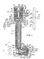
- the fuel injector 10includes a tubular support housing 20 having a flange 20a adapted to be fastened (e.g. bolted) to an engine housing 11 (shown schematically) in conventional manner and an injector tip T fastened to the support housing 20 and disposed in an opening in a gas turbine engine combustor wall 12 (partially shown) in conventional manner.
- the fuel injector 10 shownuses pressurized compressor discharge air (see arrows A) for fuel atomization as is known in the art; e.g., see U.S. Patent 3 684 186.
- the fuel injector 10is shown including the tubular support housing 20 having a fuel inlet fitting 22 that is communicated via fuel conduit 24 (shown schematically) to a fuel manifold 25.
- the manifold 25is supplied with pressurized fuel from a fuel pump 26 (shown schematically).
- a plurality of fuel injectors identical to injector 10can be supplied with pressurized fuel from the manifold 25 via similar fuel conduits 24 illustrated in Figure 1.
- the inlet fitting 22is communicated to a housing chamber 30 by passage 32.
- fuel check/fuel metering valve 34for controlling fuel flow.
- the metering valve 34is disposed on a tubular valve support member 36.
- the valve support member 36includes a circumferential flange 36A that is biased on a support cup 38 by a clip 40, spring 42, and a perforated screen or sleeve 44. In effect, the clip 40, spring 42, and sleeve 44 hold the valve support member 36 and the support cup 38 in position in the chamber 30.
- the check/metering valve 34includes a cap 50 held on the valve stem 34A by clip 52.
- a spring 54is disposed between the cap 50 and the flange 36A of the valve support member 36 as shown to bias the valve 34 to a closed position until fuel pressure reaches a preselected valve opening pressure.
- the valve 34includes a central bore 34B that received fuel from the upper region of the chamber 30. Disposed in the bore 34B is a fuel filter 56 through which the fuel flows prior to reaching the radially oriented, circumferentially spaced fuel passages 34C.
- passages 34D shown upstream of fuel passages 34Care communicated to an annular chamber 58 defined between the valve stem 34A and the valve support member 36 for providing a metered start fuel flow through passages 36B and 38B to fuel receiving chamber 64.
- This fuelmay flow through one or both of tubes 70, 72 depending on fuel flow rate and the magnitude of the pneumatic pressure differential established between fuel discharge lips 132c, 162c discussed herebelow.
- the check/fuel metering valve 34is maintained in a closed position where the radially oriented valve fuel passages 34C are blocked by the lower end 36C of the valve support member 36 as shown in Figure 1 until the fuel pressure reaches the preselected opening pressure. At that time, the valve 34 is moved downwardly against the bias of the spring 54 relative to the lower end 36C of the valve support member 36 to expose the passages 34C in a manner to provide a predetermined, controlled metered fuel flow schedule.
- the metered fuel flow from valve 34is received by the fuel receiving chamber 64 defined by the support cup 38.
- the fuel tubes or conduits 70, 72conduct the fuel to the injector tip T for discharge to the combustor chamber C (shown schematically).
- the fuel tubes or conduits 70, 72include respective upper ends 70A, 72A fastened by brazing in the support cup 38 as shown so that the open ends 70A, 72A communicate with the chamber 64 of the cup.
- the fuel tubes or conduits 70, 72are thus communicated to one another via the fuel receiving chamber 64.
- the injector tip Tcomprises a plurality of tubular injector bodies 100, 102, 104, 106, and 108 assembled together by brazing or similar metallurgical techniques.
- the tubular bodies 100 and 104are fastened by brazing and the like directly to the support housing 20.
- the other tubular bodies 102, 106 and 108are fastened by brazing to one of the bodies 100, 104 or to one another as illustrated in Figure 1.
- the inner tubular body 100defines or forms therein a cylindrical, inner air supply chamber 120 having an enlarged, upstream open end 120a for receiving the compressor discharge air from a pressurized air plenum P communicated to the engine compressor (not shown).
- the chamber 120receives the pressurized air via a plurality of circumferentially spaced air swirler vanes 121 disposed in the upstream region of the tubular body 100.
- the tubular body 100includes a downstream, frusto-conical inner air discharge chamber 122 defining an air discharge orifice 122c for discharging the inner air to the combustor chamber C.
- the air discharge orifice 122cis defined by the annular lip shown.
- the first intermediate tubular body 102is disposed about and outboard of the inner tubular body 100 (i.e. radially outward).
- the intermediate tubular body 102is fastened by brazing and the like to tubular bodies 100 and 104.
- a first, annular, inner fuel supply passage 130having an upstream opening 130a communicated to the fuel tube or conduit 70.
- the passage 130communicates with a frusto-conical fuel discharge passage 132.
- a plurality of circumferentially spaced apart fuel swirler vanes 131are disposed between the fuel supply passages 130, 132 to impart swirl to the fuel.
- the inner fuel discharge passage 132includes an annular, downstream fuel discharge orifice 132c for discharging fuel as a film or thin layer amenable for air atomization.
- the discharge orifice 132cis formed by the annular lip shown.
- the second tubular body 104is disposed about and outboard of the intermediate tubular body assembly 102 in a transverse (radial) direction and includes a plurality of circumferentially spaced apart air inlet openings 102a (one shown) that receive pressurized air from the plenum P. Between the intermediate tubular bodies 102, 104 is defined an annular intermediate air supply chamber 140 having a plurality of circumferentially spaced apart, radially extending air swirl vanes 141 therein. The air supply chamber 140 communicates with a frusto-conical air discharge chamber 142.
- the intermediate air discharge chamber 142includes an annular, downstream air discharge orifice 142c for discharging air flow for fuel atomization purposes.
- the air discharge orifice 142cis defined by the annular lip shown.
- the third intermediate tubular body 106is disposed about and outboard of the second intermediate tubular body 104 in a transverse (radial) direction.
- an annular fuel receiving passage 150that communicates to the fuel tube or conduit 72 for receiving fuel therefrom.
- the fuel receiving passage 150communicates with a frusto-conical fuel discharge passage 162 via an interconnecting fuel passage 163.
- the intermediate fuel discharge passage 162includes an annular, dowstream fuel discharge orifice 162c for discharging fuel for fuel atomization purposes.
- the fuel discharge orifice 162cis defined by the annular lip shown.
- the outer tubular body 108is disposed about and outboard of the intermediate tubular body assembly 106 in a transverse (radial) direction and includes annular air inlet opening 106a that receives pressurized air from the plenum P. Between the tubular bodies 106, 108 is defined an annular outer air supply chamber 170 having a plurality of circumferentially spaced apart, radially extending air swirl vanes 171 therein. The air supply chamber 170 communicates with a frusto-conical air discharge chamber 182.
- the outer air discharge chamber 182includes an annular, downstream air discharge orifice 182c for discharging air flow for fuel atomization purposes.
- the air discharge orifice 182cis defined by the annular lip shown.
- the air and fuel discharge orifices 122c, 132c, 142c, 162c, 182care located axially and radially as shown in Figure 1 so that the film thickness of discharging liquid fuel at fuel discharge orifices 132c, 162c can be controlled and atomized by the air discharged from the air discharge orifices 122c, 142c, 182c.
- each fuel flow stream discharged at orifices 132c, 162cis subjected to both inner and outer air atomizing flows.
- the first fuel passages 130, 132 and second fuel passages 150, 162are in communication upstream of their respective fuel discharge orifices 132c, 162c by virtue of the fuel tubes or conduits 70, 72 communicating to the common fuel receiving chamber 64 defined in the support cup 38.
- first air and fuel discharge orifices 122c, 132chave a relationship to establish a pneumatic pressure at the first fuel discharge orifice 132c and the second air and fuel discharge orifices 142c, 162c have a different relationship to establish a different pneumatic pressure at the second fuel discharge orifice 162c such that, in the event the supply of fuel to the first and second fuel discharge orifices is interrupted, for example, for engine shut-down by closure of the valve 34 resulting from deactuation of fuel pump 26, the fuel residing in the chamber 64 and fuel passages 130, 132; 150, 162 between the first and second fuel discharge orifices 132c, 162c, as well as any transient fuel in chamber 64 from passages 36B, 38A, is subjected to a sufficient pressure differential effective to purge the fuel into the combustor C through the orifice 162c having the lesser pneumatic pressure thereat than established at orifice 132c.
- a higher (e.g. relatively positive) pneumatic pressureis established at the fuel orifice 132c and a lower (e.g. relatively negative) pneumatic pressure is established at the fuel orifice 162c such that the fuel in the chamber 64 and fuel passages 130, 132; 150, 162 will be purged in a direction from the orifice 132c toward the orifice 162c for discharge from the orifice 162c into the combustor chamber C (see arrows FP in Figure 1A that illustrate a possible direction of fuel purging).
- the fuel orifice 132cis rendered a "fuel pusher" orifice and the fuel orifice 162c is rendered a "fuel puller" orifice in this embodiment.
- the relationship of the first air and fuel discharge orifices 122c, 132ccan be different from the relationship of the second air and fuel discharge orifices 142c, 162c so as to establish the different pneumatic pressures at the first and second fuel discharge orifices 132c, 162c, whereby, in the event the supply of fuel to the first and second fuel discharge orifices is interrupted by closure of the valve 34, the fuel in the chamber 64 and fuel passages 130, 132; 150, 162 between the first and second fuel discharge orifices 132c, 162c is subjected to a sufficient differential pressure effective to purge the fuel into, the combustor C through the lesser pressure orifice 162c.
- the diameter of fuel discharge orifice 132cis less than the diameter of air discharge orifice 122c while the diameter of fuel discharge orifice 162c is greater than the diameter of air discharge orifice 142c.
- the radius of the fuel discharge orifice 132cis selected in the range, for example, 0.127 mm to 0.508 mm (.005 to .020 inch), less than that of orifice 122c, while the radius of fuel discharge orifice 162c is selected in the range, for example, 0.127 mm to 0.381 mm (.005 to .015 inch), greater than that of orifice 142c, the radial dimensions being selected to provide desired self purging of the resident fuel through the lesser pressure orifice 162c. That is, the diameters of orifices 122c, 132c and 142c, 162c are selected to establish a lower pneumatic pressure at orifice 162c than established at orifice 132c.
- US-A- 5277 023describes multiple alternative means for obtaining the desired pneumatic pressures and/or pressure differentials, e.g., by means of air swirlers: "Different air discharge characteristics from the air swirlers (air injectors) 227, 229 relative to the respective first and second injectors 220, 222 may be used to establish a pressure differential on the resident fuel to purge it to the combustor.” (Col. 17, lines 37-42 of US 5,277,023).
- the differential pressure needed for fuel purgingcan be established by using fuel pusher/fuel puller orifices 132c, 162c, fuel pusher/less fuel pusher orifices 132c, 162c, or fuel puller/less fuel puller orifices 132c, 162c as mentioned in the aforementioned US Patent 5 277 023.
- FIG. 2illustrates an alternative embodiment of the invention wherein like features are represented by like reference numerals primed.
- This embodimentdiffers from the embodiment of Figure 1 in that the fuel injector is supplied with pressurized fuel from a fuel distribution valve 173' having a plurality of ports 172' each connected to an individual fuel injector (one shown) by a fuel conduit 24' (shown schematically).
- the distribution valve 173'is of known type used on the V2500 gas turbine engine made by Pratt & Whitney Aircraft, and described in U.S. Patent 4 614 202 and 4 590 768.
- the distribution valve 173'provides metered fuel flow to each fuel injector.
- the distribution valve 173'receives fuel from fuel pump 26'.
- valve 35'Since the fuel received by each fuel injector is metered by the valve 173', only a check valve 35' is provided in the fuel receiving chamber 30' of the fuel injector housing 20'.
- the check valve 35'is supported on the support cup 38' which is held in the chamber 30' by a perforated hold down sleeve 44' and spring 42'.
- the valve 35'includes a valve stem 35a' biased by spring 54' to close against valve seat 37' until fuel pressure reaches a high enough level to overcome the spring and open the valve 35'.
- the fuelflows from the chamber 30' through filter 56' and valve seat openings 37a' into the fuel receiving chamber 64' and then into fuel tubes or conduits 70', 72' to the injector tip T', which is identical in construction to injector tip T described hereabove with respect to Figure 1.
- the fuel injectorfunctions in the manner described above with respect to Figure 1 to purge fuel from the chamber 64' and fuel passages 130', 132'; 150', 162' between the first and second fuel discharge orifices 132c', 162c' into the combustor C through one of the orifices 132c' or 162c' having lesser pneumatic pressure established thereat.
- the relationship of the first air and fuel discharge orifices 122c', 132c'can be different from the relationship of the second air and fuel discharge orifices 142c', 162c' (e.g. by the selection of diameters of orifices 122c', 132c' and orifices 142c', 162c' as described above) so as to establish the different pneumatic pressures at the first and second fuel discharge orifices 132c', 162c' such that, in the event the supply of fuel to the first and second fuel discharge orifices is interrupted by closure of the valve 35', the fuel residing in the chamber 64 and fuel passages 130', 132'; 150', 162' between the first and second fuel discharge orifices 132c', 162c' is subjected to a sufficient pressure differential effective to purge the resident fuel into the combustor C in a direction from fuel orifice 132c' to fuel orifice 162c' having lesser pneumatic pressure thereat.
Landscapes
- Engineering & Computer Science (AREA)
- Chemical & Material Sciences (AREA)
- Combustion & Propulsion (AREA)
- Mechanical Engineering (AREA)
- General Engineering & Computer Science (AREA)
- Fuel-Injection Apparatus (AREA)
Description
- an injector body means having first and second air dischargeorifices for discharging air to the combustor and
- first and second fuel passage means having respective first andsecond fuel discharge orifices for discharging fuel to thecombustor.
- the first and second fuel passages are in communicationupstream of said fuel discharge orifices,
- the first air and fuel discharge orifices have a relationship toestablish a pneumatic pressure at the first fuel discharge orifice,and the second air and fuel discharge orifices have a relationshipto establish a higher pneumatic pressure at the second fueldischarge orifice,
- such that, in the event the supply of fuel to the first andsecond fuel discharge orifices is interrupted, the fuelresiding in the fuel passages between the first and secondfuel discharge orifices is subjected to a pressure differentialeffective to purge the resident fuel into the combustor.
- Figure 1
- is a longitudinal sectional view of one embodimentof a self-purging airblast injector of theinvention;
- Figure 1A
- is similar to Figure 1 showing one possibledirection of fuel purging in accordance with oneembodiment of the invention;
- Figure 2
- is a longitudinal sectional view of anotherembodiment of a self-purging airblast injector ofthe invention.
Claims (6)
- Fuel injector (10; 10') for a combustor of a gas turbine enginecomprisingcharacterized in thatan injector body means (10; 10') having first (122c; 122c') andsecond (142c; 142c') air discharge orifices for discharging air to thecombustor andfirst (130, 132; 130', 132') and second (150, 162; 150', 162') fuelpassage means having respective first (132c; 132c') and second(162c; 162c') fuel discharge orifices for discharging fuel to thecombustor,said first (130, 132; 130', 132') and second (150, 162; 150', 162')fuel passages are in communication upstream of said fuel dischargeorifices (132c; 132c'; 162c; -162c'),said first air (122c; 122c') and fuel (132c; 132c') discharge orificeshave a relationship to establish a pneumatic pressure at said firstfuel discharge orifice (132c; 132c'), and said second air (142c;142c') and fuel (162c; 162c') discharge orifices have a relationshipto establish a higher pneumatic pressure at said second fueldischarge orifice (162c; 162c'),such that, in the event the supply of fuel to the first (132c;132c') and second (162c; 162c') fuel discharge orifices isinterrupted, the fuel residing in the fuel passages (130, 132;130', 132'; 150, 162; 150', 162') between said first (132c;132c') and second (162c; 162c') fuel discharge orifices issubjected to a pressure differential effective to purge theresident fuel into the combustor.
- Fuel injector (10; 10') according to claim 1,characterized in that saidrelationship between said first air (122c; 122c') and fuel (132c; 132c')discharge orifices and/or between said second air (142c; 142c') and fuel(162c; 162c') discharge orifices is the diameter of said orifices (122c;122c'; 132c; 132c'; 142c; 142c'; 162c; 162c').
- Fuel injector (10; 10') according to claim 2,characterized in that thediameter of said first fuel discharge orifice (132c; 132c') is less than thediameter of said first air discharge orifice (122c; 122c'), and thediameter of said second fuel discharge orifice (162c; 162c') is greaterthan the diameter of said second air discharge orifice (142c; 142c').
- Fuel injector (10; 10') according to any of claims 1-3,characterized inthat said first air (122c; 122c') and fuel (132c; 132c') discharge orificescomprise an inner air discharge orifice (122c; 122c') and a fuel dischargeorifice (132c; 132c') located radially outward of said inner air dischargeorifice (122c; 122c').
- Fuel injector (10; 10') according to claim 4,characterized in that saidsecond air (142c; 142c') and fuel (162c; 162c') discharge orificescomprise an intermediate air discharge orifice (142c; 142c') locatedradially outward of said first fuel discharge orifice (132c; 132c') and anouter fuel discharge orifice (162c; 162c') located radially outward of saidintermediate air discharge orifice (142c; 142c').
- Fuel injector (10, 10') according to any of the preceding claims,characterized in that said second air discharge orifice (142c; 142c') andsaid second fuel discharge orifice (162c; 162c') are located downstreamof said first air discharge orifice (122c; 122c') and said first fueldischarge orifice (132c; 132c').
Applications Claiming Priority (3)
| Application Number | Priority Date | Filing Date | Title |
|---|---|---|---|
| US119431 | 1993-09-10 | ||
| US08/119,431US5417054A (en) | 1992-05-19 | 1993-09-10 | Fuel purging fuel injector |
| EP94109705AEP0644375B1 (en) | 1993-09-10 | 1994-06-23 | Fuel purging fuel injector |
Related Parent Applications (2)
| Application Number | Title | Priority Date | Filing Date |
|---|---|---|---|
| EP94109705ADivisionEP0644375B1 (en) | 1993-09-10 | 1994-06-23 | Fuel purging fuel injector |
| EP94109705.7Division | 1994-06-23 |
Publications (3)
| Publication Number | Publication Date |
|---|---|
| EP1069377A2 EP1069377A2 (en) | 2001-01-17 |
| EP1069377A3 EP1069377A3 (en) | 2001-03-07 |
| EP1069377B1true EP1069377B1 (en) | 2005-11-16 |
Family
ID=22384385
Family Applications (2)
| Application Number | Title | Priority Date | Filing Date |
|---|---|---|---|
| EP94109705AExpired - LifetimeEP0644375B1 (en) | 1993-09-10 | 1994-06-23 | Fuel purging fuel injector |
| EP00122123AExpired - LifetimeEP1069377B1 (en) | 1993-09-10 | 1994-06-23 | Fuel purging fuel injector |
Family Applications Before (1)
| Application Number | Title | Priority Date | Filing Date |
|---|---|---|---|
| EP94109705AExpired - LifetimeEP0644375B1 (en) | 1993-09-10 | 1994-06-23 | Fuel purging fuel injector |
Country Status (4)
| Country | Link |
|---|---|
| US (1) | US5417054A (en) |
| EP (2) | EP0644375B1 (en) |
| JP (1) | JPH0783436A (en) |
| DE (2) | DE69427059T2 (en) |
Families Citing this family (54)
| Publication number | Priority date | Publication date | Assignee | Title |
|---|---|---|---|---|
| US5701732A (en)* | 1995-01-24 | 1997-12-30 | Delavan Inc. | Method and apparatus for purging of gas turbine injectors |
| US5735117A (en)* | 1995-08-18 | 1998-04-07 | Fuel Systems Textron, Inc. | Staged fuel injection system with shuttle valve and fuel injector therefor |
| GB9708662D0 (en)* | 1997-04-30 | 1997-06-18 | Rolls Royce Plc | Fuel injector |
| US6141968A (en)* | 1997-10-29 | 2000-11-07 | Pratt & Whitney Canada Corp. | Fuel nozzle for gas turbine engine with slotted fuel conduits and cover |
| US5927067A (en)* | 1997-11-13 | 1999-07-27 | United Technologies Corporation | Self-cleaning augmentor fuel manifold |
| JPH11257664A (en)* | 1997-12-30 | 1999-09-21 | United Technol Corp <Utc> | Fuel injection nozzle / guide assembly for gas turbine engine |
| US6240731B1 (en)* | 1997-12-31 | 2001-06-05 | United Technologies Corporation | Low NOx combustor for gas turbine engine |
| US6412272B1 (en) | 1998-12-29 | 2002-07-02 | United Technologies Corporation | Fuel nozzle guide for gas turbine engine and method of assembly/disassembly |
| US6354085B1 (en)* | 2000-01-13 | 2002-03-12 | General Electric Company | Fuel injector with a fuel filter arrangement for a gas turbine engine |
| US6438963B1 (en)* | 2000-08-31 | 2002-08-27 | General Electric Company | Liquid fuel and water injection purge systems and method for a gas turbine having a three-way purge valve |
| US6675583B2 (en)* | 2000-10-04 | 2004-01-13 | Capstone Turbine Corporation | Combustion method |
| JP3986874B2 (en)* | 2001-04-23 | 2007-10-03 | 本田技研工業株式会社 | Fuel injection nozzle for gas turbine |
| DE10123708A1 (en)* | 2001-05-15 | 2002-11-21 | Alstom Switzerland Ltd | Scavenging method for fuel pipe in gas turbine plant with scavenging material, especially air mixed with liquid and/or gaseous water |
| US6921034B2 (en) | 2002-12-12 | 2005-07-26 | General Electric Company | Fuel nozzle assembly |
| US6898926B2 (en)* | 2003-01-31 | 2005-05-31 | General Electric Company | Cooled purging fuel injectors |
| US6959535B2 (en) | 2003-01-31 | 2005-11-01 | General Electric Company | Differential pressure induced purging fuel injectors |
| US6898938B2 (en)* | 2003-04-24 | 2005-05-31 | General Electric Company | Differential pressure induced purging fuel injector with asymmetric cyclone |
| US7117678B2 (en) | 2004-04-02 | 2006-10-10 | Pratt & Whitney Canada Corp. | Fuel injector head |
| US7430851B2 (en)* | 2005-01-18 | 2008-10-07 | Parker-Hannifin Corporation | Air and fuel venting device for fuel injector nozzle tip |
| GB0502438D0 (en)* | 2005-02-05 | 2005-03-16 | Alstom Technology Ltd | Fuel injection system and method of monitoring purging of the same |
| US7533531B2 (en) | 2005-04-01 | 2009-05-19 | Pratt & Whitney Canada Corp. | Internal fuel manifold with airblast nozzles |
| US7536862B2 (en)* | 2005-09-01 | 2009-05-26 | General Electric Company | Fuel nozzle for gas turbine engines |
| GB0605432D0 (en)* | 2006-03-17 | 2006-04-26 | Rolls Royce Plc | Component for fuel supply |
| US7726112B2 (en)* | 2006-04-24 | 2010-06-01 | Pratt & Whitney Canada Corp. | Fuel system of gas turbine engines |
| US8499739B2 (en)* | 2006-08-31 | 2013-08-06 | Caterpillar Inc. | Injector having tangentially oriented purge line |
| FR2911665B1 (en)* | 2007-01-22 | 2009-04-17 | Hispano Suiza Sa | FUEL INJECTOR WITH TWO FLOORS. |
| US8146365B2 (en) | 2007-06-14 | 2012-04-03 | Pratt & Whitney Canada Corp. | Fuel nozzle providing shaped fuel spray |
| US20090014561A1 (en)* | 2007-07-15 | 2009-01-15 | General Electric Company | Components capable of transporting liquids manufactured using injection molding |
| FR2919672B1 (en)* | 2007-07-30 | 2014-02-14 | Snecma | FUEL INJECTOR IN A TURBOMACHINE COMBUSTION CHAMBER |
| FR2936016B1 (en)* | 2008-09-15 | 2014-04-11 | Ge Energy Products France Snc | DEVICE AND METHOD FOR SCANNING LIQUID FUEL FOR A MULTI-COMBUSTIBLE GAS TURBINE |
| US8256226B2 (en)* | 2009-04-23 | 2012-09-04 | General Electric Company | Radial lean direct injection burner |
| US8636263B2 (en)* | 2009-08-20 | 2014-01-28 | Delavan Inc | System and method for locking retention of valve components |
| JP6043278B2 (en) | 2010-04-09 | 2016-12-14 | パシラ ファーマシューティカルズ インコーポレーテッド | Method for making multivesicular liposomes, method for preparing large diameter synthetic membrane vesicles, and evaporation apparatus |
| US8925323B2 (en) | 2012-04-30 | 2015-01-06 | General Electric Company | Fuel/air premixing system for turbine engine |
| CN105899878B (en) | 2013-06-18 | 2018-11-13 | 伍德沃德有限公司 | Gas-turbine combustion chamber component and engine and associated operating method |
| US10072578B2 (en)* | 2013-08-20 | 2018-09-11 | Safran Aircraft Engines | Method and system for injecting fuel into an engine combustion chamber |
| US10228137B2 (en)* | 2013-08-30 | 2019-03-12 | United Technologies Corporation | Dual fuel nozzle with swirling axial gas injection for a gas turbine engine |
| US9482433B2 (en) | 2013-11-11 | 2016-11-01 | Woodward, Inc. | Multi-swirler fuel/air mixer with centralized fuel injection |
| US9587833B2 (en) | 2014-01-29 | 2017-03-07 | Woodward, Inc. | Combustor with staged, axially offset combustion |
| US9546600B2 (en)* | 2014-08-12 | 2017-01-17 | General Electric Company | Nozzle having an orifice plug for a gas turbomachine |
| CN107883404B (en)* | 2016-09-30 | 2019-11-01 | 中国航发商用航空发动机有限责任公司 | Fuel nozzle, core engine and turbogenerator |
| US10378447B2 (en)* | 2016-09-30 | 2019-08-13 | General Electric Company | System and method for purging fuel or coolant from turbomachine |
| DE102017217329A1 (en)* | 2017-09-28 | 2019-03-28 | Rolls-Royce Deutschland Ltd & Co Kg | Nozzle with axially projecting air guide for a combustion chamber of an engine |
| US11118698B2 (en)* | 2018-07-23 | 2021-09-14 | Pratt & Whiiney Canada Corp. | Damping mechanism for valves |
| US11585452B2 (en) | 2019-12-03 | 2023-02-21 | Woodward, Inc. | Fuel nozzle with reduced flow tolerance |
| US11592177B2 (en) | 2021-04-16 | 2023-02-28 | General Electric Company | Purging configuration for combustor mixing assembly |
| US11913381B1 (en) | 2022-08-26 | 2024-02-27 | Hamilton Sundstrand Corporation | Force modification of passive spool for control of secondary nozzle circuits |
| US11913382B1 (en) | 2022-08-26 | 2024-02-27 | Hamilton Sundstrand Corporation | Variable restriction of a fuel circuit of a fuel nozzle |
| US11970977B2 (en)* | 2022-08-26 | 2024-04-30 | Hamilton Sundstrand Corporation | Variable restriction of a secondary circuit of a fuel injector |
| US12305581B2 (en) | 2022-08-26 | 2025-05-20 | Collins Engine Nozzles, Inc. | Proportional restriction of a secondary circuit of a fuel injector |
| US12270343B2 (en) | 2022-08-26 | 2025-04-08 | Collins Engine Nozzles, Inc. | Proportional restriction of fuel nozzle with an auxiliary circuit |
| US12286931B2 (en) | 2022-08-26 | 2025-04-29 | Collins Engine Nozzles, Inc. | Variable restriction of a fuel circuit of a fuel nozzle |
| US11970976B2 (en)* | 2022-08-26 | 2024-04-30 | Hamilton Sundstrand Corporation | Variable restriction of fuel nozzle with an auxiliary circuit |
| US12313004B2 (en) | 2022-08-26 | 2025-05-27 | Collins Engine Nozzles, Inc. | Proportional force modification of passive spool for control of secondary nozzle circuits |
Family Cites Families (39)
| Publication number | Priority date | Publication date | Assignee | Title |
|---|---|---|---|---|
| US2480019A (en)* | 1947-05-03 | 1949-08-23 | Gilbert & Barker Mfg Co | Rotary air atomizing burner |
| US2806354A (en)* | 1951-04-05 | 1957-09-17 | Rolls Royce | Fuel system with means to compensate for variations in liquid head due to accelerations acting on the fuel system |
| US2712218A (en)* | 1951-11-29 | 1955-07-05 | Westinghouse Electric Corp | Gas turbine apparatus |
| US2724239A (en)* | 1952-04-21 | 1955-11-22 | Samuel S Fox | Fuel flow distributing and manifold pressurizing valve for dual orifice fuel injection nozzles |
| US2949736A (en)* | 1952-10-03 | 1960-08-23 | Rolls Royce | Expansion joint with fuel drainage collector for ducting of gas turbine power plants |
| US2846845A (en)* | 1953-06-24 | 1958-08-12 | Gen Electric | Fuel drainage system for plural manifolds |
| US3091926A (en)* | 1959-12-16 | 1963-06-04 | Lucas Industries Ltd | Oil burners |
| US2970772A (en)* | 1960-04-14 | 1961-02-07 | Thomas H Boosinger | Fuel nozzle anti-coking cap |
| US3016705A (en)* | 1960-08-04 | 1962-01-16 | Avco Corp | Self-purging starting fuel nozzles for gas turbine engines |
| US3154095A (en)* | 1962-09-28 | 1964-10-27 | Parker Hannifin Corp | Flow divider for dual-orifice fuel injection nozzle |
| US3213918A (en)* | 1963-09-04 | 1965-10-26 | Bethlehem Steel Corp | Liquid-gaseous fuel burner |
| US3339574A (en)* | 1964-05-29 | 1967-09-05 | Gen Electric | Pressurizing and drain valve |
| GB1056477A (en)* | 1964-12-12 | 1967-01-25 | Rolls Royce | Liquid or gas supply system for a gas turbine engine |
| US3541788A (en)* | 1968-05-03 | 1970-11-24 | Bolkow Gmbh | Nozzle construction and liquid fuel rocket fuel system |
| US3521824A (en)* | 1968-10-11 | 1970-07-28 | Delavan Manufacturing Co | Air-liquid flat spray nozzle |
| GB1327280A (en) | 1969-12-10 | 1973-08-22 | Tetra Pak Int | Method of and means for sealing packaging material |
| US3684186A (en)* | 1970-06-26 | 1972-08-15 | Ex Cell O Corp | Aerating fuel nozzle |
| FR2269646B1 (en)* | 1974-04-30 | 1976-12-17 | Snecma | |
| US4028888A (en)* | 1974-05-03 | 1977-06-14 | Norwalk-Turbo Inc. | Fuel distribution manifold to an annular combustion chamber |
| US3980233A (en) | 1974-10-07 | 1976-09-14 | Parker-Hannifin Corporation | Air-atomizing fuel nozzle |
| US4170108A (en)* | 1975-04-25 | 1979-10-09 | Rolls-Royce Limited | Fuel injectors for gas turbine engines |
| GB1551725A (en)* | 1975-09-06 | 1979-08-30 | Rolls Royce | Primary systems for pumps |
| US4041695A (en)* | 1975-11-21 | 1977-08-16 | The Garrett Corporation | Fuel system pneumatic purge apparatus and method |
| DE2710618C2 (en)* | 1977-03-11 | 1982-11-11 | MTU Motoren- und Turbinen-Union München GmbH, 8000 München | Fuel injector for gas turbine engines |
| GB1602869A (en)* | 1977-11-25 | 1981-11-18 | Garrett Corp | Turbocharged internal combustion engines |
| GB2021254B (en)* | 1978-04-18 | 1982-10-27 | Lucas Industries Ltd | Fuel injector |
| US4260367A (en)* | 1978-12-11 | 1981-04-07 | United Technologies Corporation | Fuel nozzle for burner construction |
| US4262698A (en)* | 1979-12-26 | 1981-04-21 | Yardney Electric Corporation | Valve |
| US4614202A (en) | 1981-09-10 | 1986-09-30 | Ex-Cell-O Corporation | Fuel distribution valve |
| US4590768A (en) | 1981-10-15 | 1986-05-27 | Ex-Cell-O Corporation | Fuel distribution valve flow trimming and locking means |
| US4423595A (en)* | 1982-05-27 | 1984-01-03 | United Technologies Corporation | Augmentor residual fuel drain apparatus |
| US4609150A (en)* | 1983-07-19 | 1986-09-02 | United Technologies Corporation | Fuel nozzle for gas turbine engine |
| US4835962A (en)* | 1986-07-11 | 1989-06-06 | Avco Corporation | Fuel atomization apparatus for gas turbine engine |
| US4903478A (en)* | 1987-06-25 | 1990-02-27 | General Electric Company | Dual manifold fuel system |
| US4984424A (en)* | 1988-02-16 | 1991-01-15 | Sundstrand Corporation | Fuel injection system for a turbine engine |
| GB2219045B (en)* | 1988-05-27 | 1992-06-03 | Rolls Royce Plc | Gas turbine engine fuel system |
| DE3916477A1 (en)* | 1989-05-20 | 1990-11-22 | Mak Maschinenbau Krupp | Removing fuel from injection nozzle - involves releasing compressed air from storage vessel |
| US5277023A (en) | 1991-10-07 | 1994-01-11 | Fuel Systems Textron, Inc. | Self-sustaining fuel purging fuel injection system |
| US5243816A (en)* | 1992-06-19 | 1993-09-14 | Fuel Systems Textron, Inc. | Self purging fuel injector |
- 1993
- 1993-09-10USUS08/119,431patent/US5417054A/ennot_activeExpired - Lifetime
- 1994
- 1994-06-02JPJP6143993Apatent/JPH0783436A/enactivePending
- 1994-06-23DEDE69427059Tpatent/DE69427059T2/ennot_activeExpired - Lifetime
- 1994-06-23EPEP94109705Apatent/EP0644375B1/ennot_activeExpired - Lifetime
- 1994-06-23EPEP00122123Apatent/EP1069377B1/ennot_activeExpired - Lifetime
- 1994-06-23DEDE69434549Tpatent/DE69434549T2/ennot_activeExpired - Lifetime
Also Published As
| Publication number | Publication date |
|---|---|
| DE69427059T2 (en) | 2001-11-15 |
| DE69434549T2 (en) | 2006-07-20 |
| JPH0783436A (en) | 1995-03-28 |
| EP0644375A2 (en) | 1995-03-22 |
| US5417054A (en) | 1995-05-23 |
| EP1069377A2 (en) | 2001-01-17 |
| DE69434549D1 (en) | 2005-12-22 |
| EP0644375A3 (en) | 1996-04-17 |
| EP0644375B1 (en) | 2001-04-11 |
| DE69427059D1 (en) | 2001-05-17 |
| EP1069377A3 (en) | 2001-03-07 |
Similar Documents
| Publication | Publication Date | Title |
|---|---|---|
| EP1069377B1 (en) | Fuel purging fuel injector | |
| US5243816A (en) | Self purging fuel injector | |
| US5881550A (en) | Staged fuel injection system with shuttle valve and fuel injector therefor | |
| US5277023A (en) | Self-sustaining fuel purging fuel injection system | |
| EP1750056B1 (en) | Fuel injector | |
| US5505045A (en) | Fuel injector assembly with first and second fuel injectors and inner, outer, and intermediate air discharge chambers | |
| US5329760A (en) | Self-sustaining fuel purging fuel injection system | |
| US4854127A (en) | Bimodal swirler injector for a gas turbine combustor | |
| US6622488B2 (en) | Pure airblast nozzle | |
| US4337618A (en) | Gas turbine engine fuel burners | |
| EP0724115B1 (en) | Purging of gas turbine injector | |
| US4600151A (en) | Fuel injector assembly with water or auxiliary fuel capability | |
| US5014918A (en) | Airblast fuel injector | |
| EP3074697B1 (en) | Fuel nozzle with fluid lock and purge apparatus | |
| US5174504A (en) | Airblast fuel injector | |
| US4107918A (en) | Combustion assembly | |
| US5333459A (en) | Device for operating a swirler which controls combustion air of a burner for gas turbine engines | |
| US5102054A (en) | Airblast fuel injector with tubular metering valve | |
| US4938417A (en) | Airblast fuel injector with tubular metering valve | |
| US4562698A (en) | Variable area means for air systems of air blast type fuel nozzle assemblies | |
| CA1188111A (en) | Variable area means for air systems of air blast type fuel nozzle assemblies | |
| JPS597886B2 (en) | Fuel injection device for gas turbine engine | |
| EP0646707B1 (en) | Self purging fuel injector for a gas turbine engine combustor | |
| EP0646706B1 (en) | Self-sustaining fuel purging fuel injection system | |
| US4841725A (en) | Fuel spray device for gas turbine augmentor or afterburner |
Legal Events
| Date | Code | Title | Description |
|---|---|---|---|
| PUAI | Public reference made under article 153(3) epc to a published international application that has entered the european phase | Free format text:ORIGINAL CODE: 0009012 | |
| AC | Divisional application: reference to earlier application | Ref document number:644375 Country of ref document:EP | |
| AK | Designated contracting states | Kind code of ref document:A2 Designated state(s):DE FR GB | |
| PUAL | Search report despatched | Free format text:ORIGINAL CODE: 0009013 | |
| AK | Designated contracting states | Kind code of ref document:A3 Designated state(s):DE FR GB | |
| RIN1 | Information on inventor provided before grant (corrected) | Inventor name:KOBLISH, THEODORE R. Inventor name:BRADLEY, JEROME R. Inventor name:LEE, FEI PHILIP | |
| RAP1 | Party data changed (applicant data changed or rights of an application transferred) | Owner name:WOODWARD FST, INC. | |
| 17P | Request for examination filed | Effective date:20010829 | |
| AKX | Designation fees paid | Free format text:DE FR GB | |
| 17Q | First examination report despatched | Effective date:20030811 | |
| GRAP | Despatch of communication of intention to grant a patent | Free format text:ORIGINAL CODE: EPIDOSNIGR1 | |
| GRAS | Grant fee paid | Free format text:ORIGINAL CODE: EPIDOSNIGR3 | |
| GRAA | (expected) grant | Free format text:ORIGINAL CODE: 0009210 | |
| AC | Divisional application: reference to earlier application | Ref document number:0644375 Country of ref document:EP Kind code of ref document:P | |
| AK | Designated contracting states | Kind code of ref document:B1 Designated state(s):DE FR GB | |
| REG | Reference to a national code | Ref country code:GB Ref legal event code:FG4D | |
| REF | Corresponds to: | Ref document number:69434549 Country of ref document:DE Date of ref document:20051222 Kind code of ref document:P | |
| ET | Fr: translation filed | ||
| PLBE | No opposition filed within time limit | Free format text:ORIGINAL CODE: 0009261 | |
| STAA | Information on the status of an ep patent application or granted ep patent | Free format text:STATUS: NO OPPOSITION FILED WITHIN TIME LIMIT | |
| 26N | No opposition filed | Effective date:20060817 | |
| PGFP | Annual fee paid to national office [announced via postgrant information from national office to epo] | Ref country code:DE Payment date:20120627 Year of fee payment:19 | |
| PGFP | Annual fee paid to national office [announced via postgrant information from national office to epo] | Ref country code:GB Payment date:20120625 Year of fee payment:19 Ref country code:FR Payment date:20120705 Year of fee payment:19 | |
| GBPC | Gb: european patent ceased through non-payment of renewal fee | Effective date:20130623 | |
| REG | Reference to a national code | Ref country code:DE Ref legal event code:R119 Ref document number:69434549 Country of ref document:DE Effective date:20140101 | |
| REG | Reference to a national code | Ref country code:FR Ref legal event code:ST Effective date:20140228 | |
| PG25 | Lapsed in a contracting state [announced via postgrant information from national office to epo] | Ref country code:DE Free format text:LAPSE BECAUSE OF NON-PAYMENT OF DUE FEES Effective date:20140101 Ref country code:GB Free format text:LAPSE BECAUSE OF NON-PAYMENT OF DUE FEES Effective date:20130623 | |
| PG25 | Lapsed in a contracting state [announced via postgrant information from national office to epo] | Ref country code:FR Free format text:LAPSE BECAUSE OF NON-PAYMENT OF DUE FEES Effective date:20130701 |