EP1067368A1 - Level measurement device - Google Patents
Level measurement deviceDownload PDFInfo
- Publication number
- EP1067368A1 EP1067368A1EP99810606AEP99810606AEP1067368A1EP 1067368 A1EP1067368 A1EP 1067368A1EP 99810606 AEP99810606 AEP 99810606AEP 99810606 AEP99810606 AEP 99810606AEP 1067368 A1EP1067368 A1EP 1067368A1
- Authority
- EP
- European Patent Office
- Prior art keywords
- probe
- electrical
- conductivity
- medium
- measuring
- Prior art date
- Legal status (The legal status is an assumption and is not a legal conclusion. Google has not performed a legal analysis and makes no representation as to the accuracy of the status listed.)
- Withdrawn
Links
- 238000005259measurementMethods0.000titleclaimsabstractdescription23
- 239000000523sampleSubstances0.000claimsabstractdescription96
- 230000001419dependent effectEffects0.000claimsabstractdescription17
- 239000006260foamSubstances0.000claimsdescription11
- 239000007788liquidSubstances0.000claimsdescription11
- 230000001360synchronised effectEffects0.000claimsdescription3
- 230000015572biosynthetic processEffects0.000claimsdescription2
- 238000000034methodMethods0.000description4
- 238000012545processingMethods0.000description4
- 238000010586diagramMethods0.000description3
- 238000009434installationMethods0.000description3
- 210000000056organAnatomy0.000description3
- QAOWNCQODCNURD-UHFFFAOYSA-NSulfuric acidChemical compoundOS(O)(=O)=OQAOWNCQODCNURD-UHFFFAOYSA-N0.000description2
- 230000008878couplingEffects0.000description2
- 238000010168coupling processMethods0.000description2
- 238000005859coupling reactionMethods0.000description2
- 238000013461designMethods0.000description2
- 239000011810insulating materialSubstances0.000description2
- 239000008267milkSubstances0.000description2
- 210000004080milkAnatomy0.000description2
- 235000013336milkNutrition0.000description2
- 239000000126substanceSubstances0.000description2
- 230000003321amplificationEffects0.000description1
- 239000003990capacitorSubstances0.000description1
- 238000005352clarificationMethods0.000description1
- 238000004140cleaningMethods0.000description1
- 238000001514detection methodMethods0.000description1
- 238000011161developmentMethods0.000description1
- 230000018109developmental processEffects0.000description1
- 235000013305foodNutrition0.000description1
- JVTAAEKCZFNVCJ-UHFFFAOYSA-Nlactic acidChemical compoundCC(O)C(O)=OJVTAAEKCZFNVCJ-UHFFFAOYSA-N0.000description1
- 238000000691measurement methodMethods0.000description1
- 238000003199nucleic acid amplification methodMethods0.000description1
- 230000001105regulatory effectEffects0.000description1
- 230000035945sensitivityEffects0.000description1
- 201000006152substance dependenceDiseases0.000description1
- 208000011117substance-related diseaseDiseases0.000description1
- 230000007704transitionEffects0.000description1
- XLYOFNOQVPJJNP-UHFFFAOYSA-NwaterSubstancesOXLYOFNOQVPJJNP-UHFFFAOYSA-N0.000description1
Images


Classifications
- G—PHYSICS
- G01—MEASURING; TESTING
- G01F—MEASURING VOLUME, VOLUME FLOW, MASS FLOW OR LIQUID LEVEL; METERING BY VOLUME
- G01F23/00—Indicating or measuring liquid level or level of fluent solid material, e.g. indicating in terms of volume or indicating by means of an alarm
- G01F23/22—Indicating or measuring liquid level or level of fluent solid material, e.g. indicating in terms of volume or indicating by means of an alarm by measuring physical variables, other than linear dimensions, pressure or weight, dependent on the level to be measured, e.g. by difference of heat transfer of steam or water
- G01F23/26—Indicating or measuring liquid level or level of fluent solid material, e.g. indicating in terms of volume or indicating by means of an alarm by measuring physical variables, other than linear dimensions, pressure or weight, dependent on the level to be measured, e.g. by difference of heat transfer of steam or water by measuring variations of capacity or inductance of capacitors or inductors arising from the presence of liquid or fluent solid material in the electric or electromagnetic fields
- G01F23/263—Indicating or measuring liquid level or level of fluent solid material, e.g. indicating in terms of volume or indicating by means of an alarm by measuring physical variables, other than linear dimensions, pressure or weight, dependent on the level to be measured, e.g. by difference of heat transfer of steam or water by measuring variations of capacity or inductance of capacitors or inductors arising from the presence of liquid or fluent solid material in the electric or electromagnetic fields by measuring variations in capacitance of capacitors
- G01F23/266—Indicating or measuring liquid level or level of fluent solid material, e.g. indicating in terms of volume or indicating by means of an alarm by measuring physical variables, other than linear dimensions, pressure or weight, dependent on the level to be measured, e.g. by difference of heat transfer of steam or water by measuring variations of capacity or inductance of capacitors or inductors arising from the presence of liquid or fluent solid material in the electric or electromagnetic fields by measuring variations in capacitance of capacitors measuring circuits therefor
- G—PHYSICS
- G01—MEASURING; TESTING
- G01F—MEASURING VOLUME, VOLUME FLOW, MASS FLOW OR LIQUID LEVEL; METERING BY VOLUME
- G01F23/00—Indicating or measuring liquid level or level of fluent solid material, e.g. indicating in terms of volume or indicating by means of an alarm
- G01F23/22—Indicating or measuring liquid level or level of fluent solid material, e.g. indicating in terms of volume or indicating by means of an alarm by measuring physical variables, other than linear dimensions, pressure or weight, dependent on the level to be measured, e.g. by difference of heat transfer of steam or water
- G01F23/24—Indicating or measuring liquid level or level of fluent solid material, e.g. indicating in terms of volume or indicating by means of an alarm by measuring physical variables, other than linear dimensions, pressure or weight, dependent on the level to be measured, e.g. by difference of heat transfer of steam or water by measuring variations of resistance of resistors due to contact with conductor fluid
- G01F23/241—Indicating or measuring liquid level or level of fluent solid material, e.g. indicating in terms of volume or indicating by means of an alarm by measuring physical variables, other than linear dimensions, pressure or weight, dependent on the level to be measured, e.g. by difference of heat transfer of steam or water by measuring variations of resistance of resistors due to contact with conductor fluid for discrete levels
- G01F23/243—Schematic arrangements of probes combined with measuring circuits
Definitions
- the inventionrelates to a device for measuring the standing height of a particular medium in a container, in particular a liquid according to the General term of the independent claim.
- rod probesNumerous level measurements are carried out using so-called rod probes.
- a mostly smooth probe rodis dipped into the container, the probe charged with electrical energy and an electrical measurement between the probe and container or a reference electrode removed.
- Frequently used parametersare capacity and conductance.
- a typical level measuring device working according to the capacitive principleis e.g. described in DE-A-28 09 340.
- Thisis usually a rod-shaped one Measuring probe from above into the container in which to monitor the standing height of a medium is installed in an electrically insulated manner so that the probe projects into the medium.
- the probecan also extend upwards from the bottom of the container.
- the one between the probe and the wall of the container or a reference electrode Capacity or in the case of special probes the capacity of the probe itselfis then a Measure of the level of the medium in the container.
- the capacitanceis measured typically so that the probe uses AC voltage of a given frequency from e.g.
- a typical one based on the conductivity principle or specifically according to the so-called potentiometric Principle working level measuring deviceis subject e.g. US-A-4 188 826.
- a conductive, finite electrical resistoris immersed rod-shaped probe from above into the conductive medium to be measured protrudes from the bottom of the container, the probe being electrical is isolated from the container.
- the rod-shaped probeis over at both ends Connections and lines insulated from the medium with an electrical Alternating current of typically several amperes and a frequency of e.g. 5 kHz applied.
- Between the current-carrying rod probe and the container wall or a reference electrodeis a potential distribution, which in the depends essentially linearly on the level of the water level. This potential distribution or simply the electrical voltage between e.g. the submerged end of the Probe and a point of the container wall or the reference electrode, is by means of measured by an AC voltage measuring device and into an electrical standard signal converted. Details are described in detail in the document mentioned.
- the measured onedepends Value (capacity, potential difference) of the relevant electrical properties of the medium to be measured. This makes measurements with such devices at least depending on the substance and also, especially with capacitive probes, more or less installation dependent. Such measuring devices must therefore for each Application and especially the medium to be measured are calibrated.
- a particularly critical case of substance dependenceis the simultaneous existence of foam above the liquid level to be measured. Above all capacitive probes then fake the foam level as a full level, the resulting Consequences in regulated processes are often serious. For example Pumps can be damaged by running dry.
- Measuring devices operating according to the potentiometric principlefor example such as the potentiometric described in detail in said U.S. Patent No. 4,188,826 Level meter PMS 92 from the applicant, is less installation within certain limits and sensitive to medium. The foam sensitivity is also no longer in dimension relevant to practice, as long as the probe tip still has sufficient measuring medium (Measuring liquid) is covered.
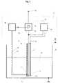
- the measuring device shown in the drawingessentially comprises a probe S and measuring electronics E which cooperate with it.
- the probe Sis designed in the form of a slim, metallically conductive rod or tube and, depending on the level to be detected, plunges more or less deeply into it during operation medium to be measured.
- the medium Mis typically, but not necessarily, in a container B.
- the probe Sis mechanically positioned at one end; this end is called the probe head S k .
- the other endis the probe tip S s .
- the probeis suspended in the lid of the container so that the probe tip is at the bottom. However, standing attachment to the bottom of the container is also possible, with the probe tip then lying on top.
- the inventionis described using the example of a hanging probe, the explanations apply analogously to a standing probe arrangement.
- the measuring electronics Eis designed according to the measuring principle used and determines a contact between the probe S and a reference point level-dependent electrical measurand and generates from this measurand Corresponding level-dependent standard output signal, which at an output A of the measuring electronics E is made available and there for display or further processing can be tapped.
- the typical reference pointis uses the container B or a point thereof; in certain applications a reference electrode immersed in the medium can also be used. In the exemplary embodiments of the invention described below, the The reference point is always the container and symbolized by the earthing symbol ⁇ .
- the level-dependent electrical measurement variableis typically the capacity of the Probe S or the potential difference of the probe S with respect to the reference point is determined.
- the modes of operation of the measuring deviceare accordingly called capacitive or potentiometric measuring principle.
- FIGS. 1-3are correct the measuring device according to the invention with e.g. by the introductory Publications documented the state of the art, so that in this regard a further explanation is unnecessary.
- the measuring electronics Ecomprise an electrical supply device in the form of an AC voltage source 10 and a converter device 20.
- the AC voltage source 10 and the converter device 20are on the one hand with the container B (reference point ⁇ ) and on the other hand via an insulated line 31, preferably led through the interior of the probe connected to the probe tip S s .
- the AC voltage source 10acts on the probe S with an AC voltage of approximately 5 kHz.
- the converter device 20measures the level-dependent capacitance prevailing between the probe S and the container B (the reference point 1) and converts it into a corresponding output signal representing the level of the medium to be measured, which is available at an output A 1 . Details of the AC voltage source 10 and the converter device 20 are described, for example, in the aforementioned DE-A-28 09 340 and therefore do not require any further explanation.
- the rod-shaped probe Sis additionally equipped with a conductivity sensor L for detecting the medium surrounding the probe.
- This conductivity sensor Lis (electrically insulated) attached to the (in use) lower end (here, therefore, at the probe tip S s ) of the probe S and, in a manner known per se, essentially consists of two electrodes L 1 and L arranged at a relatively small mutual distance 2 , which are in contact with the medium surrounding the probe (if present).
- the measuring electronics Eis equipped with a conductivity measuring device 40, which is connected to the two electrodes L 1 and L 2 of the conductivity sensor L via two insulated lines 41 and 42. In practice, the two lines 41 and 42 are guided through the interior of the probe S like the line 31.
- the conductivity measuring device 40essentially consists of an AC-fed resistance measuring bridge with an associated measuring amplifier and generates an electrical signal at its output 43 which represents the electrical conductivity of the medium surrounding the probe S.
- this signal representing the conductivity of the mediumis included as a control variable in the determination of the probe capacity and thus the level of the medium.
- the conductivity sensor Lis also operated with an alternating voltage of 5 kHz, and this alternating voltage is coupled to the alternating voltage source 10 in a phase-locked manner.
- This phase-locked couplingis indicated by the dash-dotted line 51 in FIG.
- the level-dependent output signal generated by the measuring electronics Eis how already mentioned at the beginning, various other factors, in particular also depending on the conductivity of the measuring medium.
- the measuring electronicsi.a. be calibrated with regard to the conductivity of the medium (e.g. amplification, Zero point, linearity).
- the converter device 20is conventional Level measuring devices usually with one or more manual calibration devices (e.g. adjustable resistors, adjustable capacities).
- these calibration organsare now in designed in a manner known per se to be electrically controllable, e.g.
- FIG. 2shows an embodiment of the measuring device according to the invention that works according to the potentiometric principle.
- the measuring electronics Ecomprise an electrical supply device in the form of a very low-impedance alternating current source 60 and a converter device 70 adapted to the potentiometric measuring principle connected to the probe tip S s or to the probe head S k .
- the alternating current source 60impresses the probe S with an alternating electrical current with a frequency of approximately 5 kHz.
- the converter device 70measures the level-dependent potential difference (voltage) between the probe S and the container B (the reference point shield) and converts it into a corresponding output signal representing the level of the medium to be measured. This is available at an output A 2 . Details of the alternating current source 60 and the converter device 70 are described, for example, in the aforementioned US Pat. No. 4,188,826 and therefore require no further explanation.
- a conductivity sensor LIn the same way as in the embodiment of FIG. 1 are also near the Probe tip a conductivity sensor L and in the measuring electronics E a conductivity measuring device 40 provided.
- the conductivity sensor Lis supplied with the AC power source 60 is phase locked, this coupling by the dash-dotted line 52 is symbolized.
- the converter device 70is also included electrically controllable symbolized by a voltage-controlled amplifier 50 Provide calibration organs with the output 43 of the conductivity measuring device 40 are connected.
- the measuring electronics Ecan from the conductivity measuring device generated conductivity-dependent control variable in the formation of the level-dependent Include output signal or yourself regarding the Calibrate the conductivity of the measuring medium.
- FIG 3shows a preferred embodiment of the measuring device according to the invention, where the capacitive and the potentiometric measuring principle in one single device are combined.
- the probe Sis of the same design as in the two other exemplary embodiments and also contains a conductivity sensor L.
- the measuring electronics Econtains those with the conductivity sensor L via the two lines 41 and 42 connected conductivity measuring device 40, which at its output 43 a corresponding to the conductivity of the medium surrounding the probe provides electrical signal.
- the measuring electronics Efurthermore contain an electrical feed device, which comprises an AC voltage source 10 and an AC current source 60.
- the alternating voltage source and the alternating current sourceare configured in the same way as the corresponding components of the exemplary embodiments in FIGS. 1 and 2.
- the measuring electronics Econtain a capacitive converter device 20 and a potentiometric converter device 70, which two converter devices are configured in the same way as the corresponding components in the exemplary embodiments in the figures 1 and 2.
- the AC voltage source 10, the AC power source 60 and the two converter devices 20 and 70are in an analogous manner as in the embodiments of Figures 1 and 2 on the one hand with the container B (reference point ⁇ ) and on the other hand via the two insulated lines 31 and 32 connected to the probe tip S s or to the probe head S k .
- the AC voltage source 10 and the AC power source 60act on the probe S simultaneously. To avoid mutual interference, they are synchronized in phase lock with the supply of the conductivity sensor L. The synchronization is sybolized by a dash-dotted line 53.
- the functions of the converter devices 20 and 70are the same as in the exemplary embodiments in FIGS. 1 and 2; their level-dependent output signals are available at the two outputs A 1 and A 2 .
- the measuring electronics Eis also provided with a switching device 80 which controlled by the output signal of the conductivity measuring device 40 as a control variable and depending on this either output A1 of the capacitive Converter device 20 or the output A2 of the potentiometric converter device 70 connects to device output A.
- the switching point of the switching device 80is preferably set so that with a measured conductivity of the medium above a preferably adjustable threshold value of approx. 1-2 ⁇ S (micro Siemens) the output signal of the potentiometric converter device 70 and if the value falls below this threshold, the output signal of the capacitive Converter device 20 is connected to the device output A. In this way the device depends on the electrical conductivity of the medium to be measured automatically switched from potentiometric to capacitive mode or switched and thus automatically optimally adapted to the measuring medium.
- the switching device 80is simpler Clarification of the principle downstream of the two converter devices 20 and 70. It goes without saying that a corresponding switchover also within the two converter devices or at their inputs.
- the conductivity measuring device generated output signalcan also be evaluated for the detection of foam.
- the output signalbecomes a discriminator provided in the measuring electronics E. 90 supplied, which it with a preferably adjustable foam threshold (very low conductance) and compares an electrical the presence of foam indicating signal is generated when the measured Conductivity value of the medium is below or below the foam threshold this falls.
- the probe Scan also be used with a sensor T known per se for detecting the Temperature of the medium surrounding the probe can be provided, which with a in of the measuring electronics E provided temperature measuring device 100 preferably lines 101 and 102 routed through the interior of the probe are connected and works together.
- the recorded temperature of the mediumcan be in different forms output and evaluated.
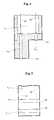
- the probemust be relatively slim (e.g. 6mm outside diameter) be trained.
- the conductivity sensor L and the probe Sim Area of the conductivity sensor F designed so that no liquid drops hang remain and can cause incorrect measurements.
- Two of these requirements Sufficient implementation forms for the probe Sare shown in the figures 4 and 5 are shown schematically.
- the lowermost part of the probe S -here the probe tip S s - is formed from an insulating material and shaped in a stepped manner.
- the two electrodes L 11 and L 12are pin-shaped and arranged axially parallel.
- the gradation and the lowermost end of the probe Sare relatively sharp-edged.
- the lowermost part of the probe Salso consists of an insulating material.
- the two electrodes L 21 and L 22are designed here as parallel concave rings, the transitions between the two electrode rings and the adjacent cylindrical sections of the probe S forming relatively sharp tear-off edges 46 which prevent the two electrodes from being bridged by liquid drops.
- the bridging and thus an incorrect measurementcan also by other configurations and arrangements of the electrodes of the conductivity sensor L can be avoided.
- the wettabilitymust be taken into account and the adhesiveness of the medium.
- the Probe Sdistributed to arrange two or more conductivity sensors. With that, then e.g. the location of the boundary layer of two different ones, characterized by the conductivity sufficiently different media are recorded. It is also possible display the measured conductivity of the medium as such or e.g. in form of To provide standard signals for further processing.
Landscapes
- Physics & Mathematics (AREA)
- Engineering & Computer Science (AREA)
- Power Engineering (AREA)
- Thermal Sciences (AREA)
- Fluid Mechanics (AREA)
- General Physics & Mathematics (AREA)
- Electromagnetism (AREA)
- Investigating Or Analyzing Materials By The Use Of Electric Means (AREA)
Abstract
Description
Translated fromGermanDie Erfindung betrifft eine Vorrichtung zur Messung der Standhöhe eines insbesonderein einem Behälter befindlichen Mediums, insbesondere einer Flüssigkeit gemäss demOberbegriff des unabhängigen Anspruchs.The invention relates to a device for measuring the standing height of a particularmedium in a container, in particular a liquid according to theGeneral term of the independent claim.
Zahlreiche Füllstandsmessungen werden mit Hilfe sogenannter Stabsonden durchgeführt.Hierbei wird ein meist glatter Sondenstab in den Behälter getaucht, die Sondemit elektrischer Energie beaufschlagt und eine elektrische Messgrösse zwischen Sondeund Behälter oder einer Referenz-Elektrode abgenommen. Häufig verwendete Messgrössensind Kapazität und Leitwert.Numerous level measurements are carried out using so-called rod probes.Here a mostly smooth probe rod is dipped into the container, the probecharged with electrical energy and an electrical measurement between the probeand container or a reference electrode removed. Frequently used parametersare capacity and conductance.
Eine typische nach dem kapazitiven Prinzip arbeitende Pegelstandsmessvorrichtung istz.B. in der DE-A-28 09 340 beschrieben. Hierbei wird eine in der Regel stabförmigeMessonde von oben so in das Behältnis, in dem die Standhöhe eines Mediums zu überwachenist, elektrisch isoliert eingebaut, dass die Sonde in das Medium hineinragt. Alternativkann sich die Sonde auch vom Boden des Behältnisses nach oben erstrecken.Die zwischen der Sonde und der Behältniswand oder einer Referenz-Elektrode herrschendeKapazität oder bei Spezialsonden die Kapazität der Sonde selbst ist dann einMass für den Pegelstand des Mediums im Behältnis. Die Messung der Kapazität erfolgttypischerweise so, dass die Sonde mit Wechselspannung einer vorgegebenen Frequenzvon z.B. 5 kHz beaufschlagt wird und die Kapazität als zeitbestimmendes Elementin einer Zeitschaltstufe verwendet wird, welche ein Ausgangssignal von der Kapazitätder Sonde entsprechender Dauer erzeugt, das dann in ein in der Industrie üblichesNorm-Signal (z.B. Strom 4-20 mA oder Spannung 0-10 V entsprechend den Pegelstandsgrenzwerten"leer" bzw. "voll") aufbereitet wird. Schaltungstechniken zurRealisierung von Kapazitätsmessungen und zur Weiterverarbeitung in Normsignalesind dem Fachmann geläufig und z.B. ebenfalls im genannten Dokument im Detail beschrieben.A typical level measuring device working according to the capacitive principle ise.g. described in DE-A-28 09 340. This is usually a rod-shaped oneMeasuring probe from above into the container in which to monitor the standing height of a mediumis installed in an electrically insulated manner so that the probe projects into the medium. Alternativelythe probe can also extend upwards from the bottom of the container.The one between the probe and the wall of the container or a reference electrodeCapacity or in the case of special probes the capacity of the probe itself is then aMeasure of the level of the medium in the container. The capacitance is measuredtypically so that the probe uses AC voltage of a given frequencyfrom e.g. 5 kHz is applied and the capacity as a time-determining elementis used in a time switch which has an output signal from the capacitanceof the probe of the appropriate duration, which is then customary in the industryStandard signal (e.g. current 4-20 mA or voltage 0-10 V according to the level limit values"empty" or "full") is processed. Circuit techniques forRealization of capacity measurements and for further processing in standard signalsare familiar to the person skilled in the art and e.g. also described in detail in the document mentioned.
Eine typische nach dem Leitfähigkeitsprinzip bzw. speziell nach dem sogenannten potentiometrischenPrinzip arbeitende Pegelstandsmessvorrichtung ist Gegenstand z.B.der US-A-4 188 826. Hierbei taucht eine leitfähige, einen endlichen elektrischen Widerstand aufweisende stabförmige Sonde von oben in das zu messende, leitfähige Mediumein bzw. ragt vom Boden des Behältnisses nach oben, wobei die Sonde elektrischvom Behälter isoliert ist. Die stabförmige Sonde wird über an ihren beiden Enden befindlicheAnschlüsse und vom Medium isolierte Leitungen mit einem elektrischenWechselstrom von typischerweise mehreren Ampere und einer Frequenz von z.B. 5kHz beaufschlagt. Zwischen der stromdurchflossenen Stabsonde und der Behälterwandbzw. einer Referenz-Elektrode stellt sich eine Potentialverteilung ein, welche imwesentlichen linear von der Höhe des Pegelstands abhängt. Diese Potentialverteilungbzw. einfach die elektrische Spannung zwischen z.B. dem eingetauchten Ende derSonde und einem Punkt der Behälterwand oder der Referenz-Elektrode, wird mittelseiner Wechselspannungsmessvorrichtung gemessen und in ein elektrisches Normsignalumgewandelt. Details sind im genannten Dokument ausführlich beschrieben.A typical one based on the conductivity principle or specifically according to the so-called potentiometricPrinciple working level measuring device is subject e.g.US-A-4 188 826. A conductive, finite electrical resistor is immersedrod-shaped probe from above into the conductive medium to be measuredprotrudes from the bottom of the container, the probe being electricalis isolated from the container. The rod-shaped probe is over at both endsConnections and lines insulated from the medium with an electricalAlternating current of typically several amperes and a frequency of e.g. 5kHz applied. Between the current-carrying rod probe and the container wallor a reference electrode is a potential distribution, which in thedepends essentially linearly on the level of the water level. This potential distributionor simply the electrical voltage between e.g. the submerged end of theProbe and a point of the container wall or the reference electrode, is by means ofmeasured by an AC voltage measuring device and into an electrical standard signalconverted. Details are described in detail in the document mentioned.
Bei diesen bekannten Messvorrichtungen bzw. Messprinzipien hängt der gemesseneWert (Kapazität, Potential-Differenz) von den betreffenden elektrischen Eigenschaftendes zu messenden Mediums ab. Dadurch sind Messungen mit solchen Vorrichtungenzumindest stoffabhängig sowie auch, insbesondere bei kapazitiven Sonden, mehr oderweniger einbauabhängig. Derartige Messvorrichtungen müssen also für den jeweiligenEinsatzfall und speziell das zu messende Medium kalibriert werden.With these known measuring devices or measuring principles, the measured one dependsValue (capacity, potential difference) of the relevant electrical propertiesof the medium to be measured. This makes measurements with such devicesat least depending on the substance and also, especially with capacitive probes, more orless installation dependent. Such measuring devices must therefore for eachApplication and especially the medium to be measured are calibrated.
Ein besonders kritischer Fall von Stoffabhängigkeit ist das gleichzeitige Vorhandenseinvon Schaum über dem zu messenden Flüssigkeitsstand. Vor allem kapazitive Sondentäuschen dann den Schaumpegel als vollen Füllstand vor, wobei die daraus resultierendenFolgen in geregelten Prozessen oft schwerwiegend sind. Beispielsweise könnenPumpen durch Trockenlaufen beschädigt werden.A particularly critical case of substance dependence is the simultaneous existenceof foam above the liquid level to be measured. Above all capacitive probesthen fake the foam level as a full level, the resultingConsequences in regulated processes are often serious. For examplePumps can be damaged by running dry.
Nach dem potentiometrischen Prinzip arbeitende Messvorrichtungen, beispielsweiseetwa der in der genannten US-A-4 188 826 im Detail beschriebene PotentiometrischeFüllstandsmesser PMS 92 der Anmelderin, ist in gewissen Grenzen weniger Einbau-und Messstoff-empfindlich. Auch die Schaumempfindlichkeit besteht nicht mehr inpraxisrelevantem Ausmass, solange die Sondenspitze noch ausreichend mit Messmedium(Messflüssigkeit) bedeckt ist.Measuring devices operating according to the potentiometric principle, for examplesuch as the potentiometric described in detail in said U.S. Patent No. 4,188,826Level meter PMS 92 from the applicant, is less installation within certain limitsand sensitive to medium. The foam sensitivity is also no longer indimension relevant to practice, as long as the probe tip still has sufficient measuring medium(Measuring liquid) is covered.
In vielen Fällen realer Prozesse ist diese Voraussetzung jedoch nicht gegeben. So trittbeispielsweise bei Abscheidebehältern in der Milchverarbeitung der typische Fall ein,dass der Behälter mit weit mehr als der Hälfte seiner Füllkapazität mit Schaum gefülltist, ohne dass sich noch Messflüssigkeit im Behälter befindet. In solchen Fällen versagt auch der genannte Potentiometrische Füllstandsmesser PMS 92. Hinzu kommt nocherschwerend, dass die Sonde in derartigen Behältern stehend im Boden und nicht wiesonst meist üblich hängend im Deckel eingebaut werden soll.In many cases of real processes, however, this requirement is not met. So occursfor example, with separating tanks in milk processing, the typical case,that the container is filled with foam with far more than half of its filling capacitywithout any measuring liquid in the container. Failed in such casesalso the mentioned potentiometric level meter PMS 92. In addition there iscomplicating that the probe in such containers standing in the ground and not likeotherwise usually to be installed hanging in the lid.
Auch kann die verbliebene Abhängigkeit von der Leitfähigkeit des Messstoffs im Fallesehr grosser Unterschiede, z.B. zwischen Milch und Schwefelsäure, wie es beim Reinigenvon Tanks in der Lebensmittelindustrie vorkommt, Schwierigkeiten bereiten.The remaining dependence on the conductivity of the medium in the case can alsovery large differences, e.g. between milk and sulfuric acid, as is the case with cleaningof tanks in the food industry can cause difficulties.
In anderen Prozessen treten wechselseitig leitfähige und nichtleitende Messstoffe (z.B.Öl) auf. Die bekannten Füllstandsmessverfahren sind für diese Fälle nur sehr bedingttauglich. Insbesondere versagt der potentiometrische Füllstandsmesser PMS 92 beinichtleitenden Stoffen trotz seiner sonst sehr vorteilhaften Eigenschaften vollständig.In other processes, mutually conductive and non-conductive media (e.g.Oil). The known level measurement methods are only very limited for these casessuitable. In particular, the potentiometric level meter PMS 92 failsnon-conductive substances despite its otherwise very advantageous properties completely.
Es stellt sich also die Aufgabe, eine Vorrichtung zur Messung des Füllstands von insbesondereflüssigen Medien so zu verbessern, dass sie nicht nur - in Grenzen - messmedium-und einbauunempfindlich ist, sondern auch noch in der Lage ist, beim Auftretenvon übermässigem Schaum eine Fehlmessung zu vermeiden. Ausserdem solldiese Vorrichtung auch für wechselnde Medien mit sehr grossen Leitfähigkeitsunterschiedengeeignet sein. Schliesslich soll die Vorrichtung gleichermassen für leitendeund nichtleitende Messmedien geeignet sein.It is therefore the task of a device for measuring the fill level in particularto improve liquid media so that they not only - within limits -and is insensitive to installation, but is also still able to occurto avoid incorrect measurement of excessive foam. In addition, shouldthis device also for changing media with very large conductivity differencesbe suitable. Finally, the device is intended for both conductiveand non-conductive measuring media.
Die Lösung dieser der Erfindung zugrundeliegenden Aufgabe ergibt sich aus den imkennzeichnenden Teil des unabhängigen Anspruchs 1 beschriebenen Merkmalen. Besondersvorteilhafte Ausgestaltungen und Weiterbildungen sind Gegenstand der abhängigenAnsprüche.The solution to this problem underlying the invention results from the imcharacterizing part of the
Im folgenden wird die Erfindung anhand der Zeichnung näher erläutert. Es zeigen:
- Fig. 1
- ein Prinzipschema eines ersten, nach dem kapazitiven Prinzip arbeitendenAusführungsbeispiels der erfindungsgemässen Messvorrichtung,
- Fig. 2
- ein Prinzipschema eines zweiten, nach dem potentiometrischen Prinzip arbeitendenAusführungsbeispiels der erfindungsgemässen Messvorrichtung,
- Fig. 3
- ein Prinzipschema eines dritten, sowohl nach dem kapazitiven als auchnach dem potentiometrischen Prinzip arbeitenden Ausführungsbeispiels dererfindungsgemässen Messvorrichtung,
- Fig. 4
- eine schematische Skizze einer ersten konkreten Realisierungsform desLeitfähigkeitsfühlers der Messvorrichtung und
- Fig. 5
- eine schematische Skizze einer zweiten Realisierungsform des Leitfähigkeitsfühlersder erfindungsgemässen Messvorrichtung.
- Fig. 1
- 1 shows a basic diagram of a first exemplary embodiment of the measuring device according to the invention, which works according to the capacitive principle,
- Fig. 2
- 1 shows a basic diagram of a second exemplary embodiment of the measuring device according to the invention, which works according to the potentiometric principle,
- Fig. 3
- 1 shows a basic diagram of a third exemplary embodiment of the measuring device according to the invention, which works both according to the capacitive and the potentiometric principle,
- Fig. 4
- a schematic sketch of a first concrete implementation of the conductivity sensor of the measuring device and
- Fig. 5
- a schematic sketch of a second implementation of the conductivity sensor of the measuring device according to the invention.
Die in der Zeichnung dargestellte Messvorrichtung umfasst im wesentlichen eine SondeS und eine mit dieser zusammenwirkende Messelektronik E. Die Sonde S ist inForm eines schlanken, metallisch leitenden Stabs oder Rohrs ausgebildet und taucht imBetrieb abhängig vom zu erfassenden Pegelstand mehr oder weniger tief in das zumessende Medium ein. Das Medium M befindet sich typischerweise, aber nicht notwendig,in einem Behältnis B. Die Sonde S ist an ihrem einen Ende mechanisch positioniert;dieses Ende wird als Sondenkopf Sk bezeichnet. Das andere Ende ist die SondenspitzeSs. Typischerweise ist die Sonde hängend im Deckel des Behältnisses befestigt,so dass die Sondenspitze unten liegt. Es ist jedoch auch eine stehende Befestigungam Boden des Behältnisses möglich, wobei dann die Sondenspitze oben liegt. Imfolgenden wird die Erfindung am Beispiel einer hängend angeordneten Sonde beschrieben,bei stehender Sondenanordnung gelten die Ausführungen sinngemäss.The measuring device shown in the drawing essentially comprises a probe S and measuring electronics E which cooperate with it. The probe S is designed in the form of a slim, metallically conductive rod or tube and, depending on the level to be detected, plunges more or less deeply into it during operation medium to be measured. The medium M is typically, but not necessarily, in a container B. The probe S is mechanically positioned at one end; this end is called the probe head Sk . The other end is the probe tip Ss . Typically, the probe is suspended in the lid of the container so that the probe tip is at the bottom. However, standing attachment to the bottom of the container is also possible, with the probe tip then lying on top. In the following, the invention is described using the example of a hanging probe, the explanations apply analogously to a standing probe arrangement.
Die Messelektronik E ist je nach dem zur Anwendung gelangenden Messprinzip ausgebildetund ermittelt eine zwischen der Sonde S und einem Bezugspunkt anliegende,pegelstandsabhängige elektrische Messgrösse und erzeugt aus dieser Messgrösse einentsprechendes pegelstandsabhängiges Norm-Ausgangssignal, welches an einem AusgangA der Messelektronik E zur Verfügung gestellt wird und dort zur Anzeige oderweiteren Verarbeitung abgegriffen werden kann. Als Bezugspunkt wird typischerweisedas Behältnis B bzw. ein Punkt desselben verwendet; in gewissen Anwendungsfällenkann aber auch eine in das Medium eintauchende Referenz-Elektrode eingesetzt werden.Bei den im folgenden beschriebenen Ausführungsbeispielen der Erfindung ist derBezugspunkt stets das Behältnis und durch das Erdungszeichen ┴ symbolisiert. Alspegelstandsabhängige elektrische Messgrösse wird typischerweise die Kapazität derSonde S oder die Potentialdifferenz der Sonde S bezüglich des Bezugspunkts bestimmt.Die Arbeitsweisen der Messvorrichtung werden entsprechend als kapazitivesbzw. potentiometrisches Messprinzip bezeichnet.The measuring electronics E is designed according to the measuring principle usedand determines a contact between the probe S and a reference pointlevel-dependent electrical measurand and generates from this measurandCorresponding level-dependent standard output signal, which at an outputA of the measuring electronics E is made available and there for display orfurther processing can be tapped. The typical reference point isuses the container B or a point thereof; in certain applicationsa reference electrode immersed in the medium can also be used.In the exemplary embodiments of the invention described below, theThe reference point is always the container and symbolized by the earthing symbol ┴. AsThe level-dependent electrical measurement variable is typically the capacity of theProbe S or the potential difference of the probe S with respect to the reference point is determined.The modes of operation of the measuring device are accordingly called capacitiveor potentiometric measuring principle.
In dieser Allgemeinheit stimmen die in den Figuren 1-3 gezeigten Ausführungsbeispieleder erfindungsgemässen Messvorrichtung mit dem z.B. durch die einleitend angeführten Druckschriften dokumentierten Stand der Technik überein, so dass sich diesbezüglicheine nähere Erläuterung erübrigt.In this generality, the exemplary embodiments shown in FIGS. 1-3 are correctthe measuring device according to the invention with e.g. by the introductoryPublications documented the state of the art, so that in this regarda further explanation is unnecessary.
Die Fig. 1 zeigt ein nach dem kapazitiven Prinzip arbeitendes Ausführungsbeispiel dererfindungsgemässen Messvorrichtung. Hier umfasst die Messelektronik E eine elektrischeSpeiseeinrichtung in Form einer Wechselspannungsquelle 10 und eine Wandlereinrichtung20. Die Wechselspannungsquelle 10 und die Wandlereinrichtung 20 sindeinerseits mit dem Behältnis B (Bezugspunkt ┴) und anderseits über eine isolierte, vorzugsweisedurch das Innere der Sonde geführte Leitung 31 mit der Sondenspitze Ssverbunden. Die Wechselspannungsquelle 10 beaufschlagt die Sonde S mit einer Wechselspannungvon ca. 5 kHz. Die Wandlereinrichtung 20 misst die zwischen der SondeS und dem Behältnis B (dem Bezugspunkt 1) herrschende pegelstandsabhängige Kapazitätund setzt diese in ein entsprechendes, die Standhöhe des zu messenden Mediumsrepräsentierendes Ausgangssignal um, das an einem Ausgang A1 zur Verfügungsteht. Details der Wechselspannungsquelle 10 und der Wandlereinrichtung 20 sind z.B.in der eingangs genannten DE-A-28 09 340 beschrieben und bedürfen daher keinernäheren Erläuterung.1 shows an embodiment of the measuring device according to the invention, which works according to the capacitive principle. Here, the measuring electronics E comprise an electrical supply device in the form of an
Gemäss einem ersten wesentlichen Aspekt der Erfindung ist die stabförmige SondeS zusätzlich mit einem Leitfähigkeitsfühler L zur Erfassung des die Sonde umgebendenMediums ausgestattet. Dieser Leitfähigkeitsfühler L ist (elektrisch isoliert) am (im Einsatz)unteren Ende (hier also an der Sondenspitze Ss) der Sonde S angebracht und bestehtin an sich bekannter Weise im wesentlichen aus zwei im relativ geringen gegenseitigenAbstand angeordneten Elektroden L1 und L2, die mit dem die Sonde umgebendenMedium (sofern vorhanden) in Kontakt stehen. Die Messelektronik E ist miteiner Leitfähigkeitsmesseinrichtung 40 ausgestattet, welche mit den beiden ElektrodenL1 und L2 des Leitfähigkeitsfühlers L über zwei isolierte Leitungen 41 und 42 verbundenist. Die beiden Leitungen 41 und 42 sind in der Praxis wie die Leitung 31 durchdas Innere der Sonde S geführt. Die Leitfähigkeitsmesseinrichtung 40 besteht in ansich bekannter Weise im wesentlichen aus einer wechselstromgespeisten Widerstandsmessbrückemit zugeordnetem Messverstärker und erzeugt an ihrem Ausgang 43 einelektrisches Signal, welches die elektrische Leitfähigkeit des die Sonde S umgebendenMediums repräsentiert. Dieses die Leitfähigkeit des Mediums repräsentierende Signalwird gemäss einem weiteren wesentlichen Aspekt der Erfindung als Steuergrösse indie Ermittlung der Sondenkapazität und damit der Standhöhe des Mediums mit einbezogen.According to a first essential aspect of the invention, the rod-shaped probe S is additionally equipped with a conductivity sensor L for detecting the medium surrounding the probe. This conductivity sensor L is (electrically insulated) attached to the (in use) lower end (here, therefore, at the probe tip Ss ) of the probe S and, in a manner known per se, essentially consists of two electrodes L1 and L arranged at a relatively small mutual distance2 , which are in contact with the medium surrounding the probe (if present). The measuring electronics E is equipped with a
Damit sich die Leitfähigkeitsmessung und die Kapazitätsmessung nicht gegenseitigstörend beeinflussen, sind die die Sonde S beaufschlagende elektrische Wechselspannungund die die Elektroden L1 und L2 des Leitfähigkeitsfühlers L beaufschlagendeWechselspannung synchronisiert. Das heisst, der Leitfähigkeitsfühler L wird ebenfallsmit einer Wechselspannung von 5 kHz betrieben, und diese Wechselspannung ist phasenstarran die Wechselspannungsquelle 10 gekoppelt. In der Figur 1 ist diese phasenstarreKopplung durch die strichpunktierte Linie 51 angedeutet.So that the conductivity measurement and the capacitance measurement do not interfere with one another, the electrical AC voltage acting on the probe S and the AC voltage acting on the electrodes L1 and L2 of the conductivity sensor L are synchronized. This means that the conductivity sensor L is also operated with an alternating voltage of 5 kHz, and this alternating voltage is coupled to the alternating
Das von der Messelektronik E erzeugte pegelstandsabhängige Ausgangssignal ist, wieschon eingangs erwähnt, noch von verschiedenen anderen Faktoren, insbesondere auchder Leitfähigkeit des Messmediums abhängig. Aus diesem Grund muss die Messelektroniku.a.a. bezüglich der Leitfähigkeit des Mediums kalibriert werden (z.B. Verstärkung,Nullpunkt, Linearität). Dazu ist die Wandlereinrichtung 20 bei herkömmlichenPegelstandsmessvorrichtungen üblicherweise mit einem oder mehreren manuellen Kalibrierorganen(z.B. einstellbare Widerstände, einstellbare Kapazitäten) versehen. Gemässeinem weiteren wichtigen Aspekt der Erfindung sind nun diese Kalibierorgane inan sich bekannter Weise elektrisch steuerbar ausgebildet, z.B. als spannungsgesteuerteWiderstände, spannungsgesteuerte Kapazitäten oder spannungsgesteuerte Verstärker,wobei alle diese elektrisch steuerbaren Kalibrierorgane in der Zeichnung durch einenspannungsgesteuerten Verstärker 50 innerhalb der Wandlereinrichtung 20 symbolisiertsind. Diese elektrisch gesteuerten Kalibrierorgane sind mit dem Ausgang 43 der Leitfähigkeitsmesseinrichtung40 verbunden und werden dadurch mit dem von dieser erzeugten,leitfähigkeitsabhängigen elektrischen Ausgangssignal als Steuergrösse beaufschlagt.Auf diese Weise kann sich die Messelektronik E bezüglich der Leitfähigkeitdes Messmediums selbst kalibrieren.The level-dependent output signal generated by the measuring electronics E is howalready mentioned at the beginning, various other factors, in particular alsodepending on the conductivity of the measuring medium. For this reason, the measuring electronicsi.a. be calibrated with regard to the conductivity of the medium (e.g. amplification,Zero point, linearity). For this purpose, the
Die Fig. 2 zeigt ein nach dem potentiometrischen Prinzip arbeitendes Ausführungsbeispielder erfindungsgemässen Messvorrichtung. Hier umfasst die Messelektronik E eineelektrische Speiseeinrichtung in Form einer sehr niederohmigen Wechselstromquelle60 und eine dem potentiometrischen Messprinzip angepasste Wandlereinrichtung 70.Die Wechselstromquelle 60 und die Wandlereinrichtung 70 sind einerseits mit demBehältnis B (Bezugspunkt ┴) und anderseits über zwei isolierte Leitungen 31 und 32mit der Sondenspitze Ss bzw. mit dem Sondenkopf Sk verbunden. Die Wechselstromquelle60 prägt der Sonde S einen elektrischen Wechselstrom mit einer Frequenz vonca. 5 kHz ein. Die Wandlereinrichtung 70 misst die zwischen der Sonde S und demBehältnis B (dem Bezugspunkt ┴) herrschende pegelstandsabhängige Potentialdifferenz(Spannung) und setzt diese in ein entsprechendes, die Standhöhe des zu messenden Mediums repräsentierendes Ausgangssignal um. Dieses steht an einem AusgangA2 zur Verfügung. Details der Wechselstromquelle 60 und der Wandlereinrichtung 70sind z.B. in der eingangs genannten US-A-4 188 826 beschrieben und bedürfen daherkeiner näheren Erläuterung.FIG. 2 shows an embodiment of the measuring device according to the invention that works according to the potentiometric principle. Here, the measuring electronics E comprise an electrical supply device in the form of a very low-impedance alternating
In gleicher Weise wie beim Ausführungsbeispiel der Fig. 1 sind ferner in der Nähe derSondenspitze ein Leitfähigkeitsfühler L und in der Messelektronik E eine Leitfähigkeitsmesseinrichtung40 vorgesehen. Die Speisung des Leitfähigkeitsfühlers L ist mitder Wechselstromquelle 60 phasenstarr gekoppelt, wobei diese Kopplung durch diestrichpunktierte Linie 52 symbolisiert ist. Die Wandlereinrichtung 70 ist ferner mitdurch einen spannungsgesteuerten Verstärker 50 symbolisierten elektrisch steuerbarenKalibrierorganen versehen, die mit dem Ausgang 43 der Leitfähigkeitsmesseinrichtung40 verbunden sind. Somit kann die Messelektronik E die von der Leitfähigkeitsmesseinrichtungerzeugte leitfähigkeitsabhängige Steuergrösse in die Bildung des pegelstandsabhängigenAusgangssignals mit einbeziehen bzw. sich selbst bezüglich derLeitfähigkeit des Messmediums kalibrieren.In the same way as in the embodiment of FIG. 1 are also near theProbe tip a conductivity sensor L and in the measuring electronics E a
Die Fig. 3 zeigt ein bevorzugtes Ausführungsbeispiel der erfindungsgemässen Messvorrichtung,bei dem das kapazitive und das potentiometrische Messprinzip in einereinzigen Vorrichtung kombiniert sind.3 shows a preferred embodiment of the measuring device according to the invention,where the capacitive and the potentiometric measuring principle in onesingle device are combined.
Die Sonde S ist gleich ausgebildet wie bei den beiden anderen Ausführungsbeispielenund enthält ebenfalls wieder einen Leitfähigkeitsfühler L.The probe S is of the same design as in the two other exemplary embodimentsand also contains a conductivity sensor L.
Die Messelektronik E enthält die mit dem Leitfähigkeitsfühler L über die beiden Leitungen41 und 42 verbundene Leitfähigkeitsmesseinrichtung 40, welche an ihrem Ausgang43 ein der Leitfähigkeit des die Sonde umgebenden Mediums entsprechendeselektrisches Signal bereitstellt.The measuring electronics E contains those with the conductivity sensor L via the two
Die Messelektronik E enthält ferner eine elektrische Speiseeinrichtung, die eine Wechselspannungsquelle10 und eine Wechselstromquelle 60 umfasst. Die Wechselspannungsquelleund die Wechselstromquelle sind gleich ausgebildet wie die entsprechendenKomponenten der Ausführungsbeispiele der Figuren 1 bzw. 2. Ferner enthält dieMesselektronik E eine kapazitive Wandlereinrichtung 20 und eine potentiometrischeWandlereinrichtung 70, welche beiden Wandlereinrichtungen gleich ausgebildet sindwie die entsprechenden Komponenten der Ausführungsbeispiele der Figuren 1 bzw. 2.Die Wechselspannungsquelle 10, die Wechselstromquelle 60 und die beiden Wandlereinrichtungen 20 und 70 sind in analoger Weise wie bei den Ausführungsbeispielender Figuren 1 und 2 einerseits mit dem Behältnis B (Bezugspunkt ┴) und anderseitsüber die zwei isolierten Leitungen 31 und 32 mit der Sondenspitze Ss bzw. mit demSondenkopf Sk verbunden. Die Wechselspannungsquelle 10 und die Wechselstromquelle60 beaufschlagen die Sonde S gleichzeitig. Sie sind zur Vermeidung der gegenseitigenstörenden Beeinflussung untereinander und mit der Speisung des LeitfähigkeitsfühlersL phasenstarr synchronisiert. Die Synchronisierung ist durch eine strichpunktierteLinie 53 sybolisiert. Die Funktionen der Wandlereinrichtungen 20 und 70sind gleich wie bei den Ausführungsbeispielen der Figuren 1 bzw. 2; ihre pegelstandsabhängigenAusgangssignale stehen an den beiden Ausgängen A1 bzw. A2 zur Verfügung.The measuring electronics E furthermore contain an electrical feed device, which comprises an
Die Messelektronik E ist ferner mit einer Umschalteinrichtung 80 versehen, welchevom Ausgangssignal der Leitfähigkeitsmesseinrichtung 40 als Steuergrösse angesteuertwird und in Abhängigkeit von dieser entweder den Ausgang A1 der kapazitivenWandlereinrichtung 20 oder den Ausgang A2 der potentiometrischen Wandlereinrichtung70 mit dem Vorrichtungsausgang A verbindet. Der Umschaltpunkt der Umscalteinrichtung80 ist dabei vorzugsweise so eingestellt, dass bei einer gemessenen Leitfähigkeitdes Mediums über einem vorzugsweise einstellbaren Schwellenwert von ca. 1-2µS (Mikro Siemens) das Ausgangssignal der potentiometrischen Wandlereinrichtung70 und bei Unterschreitung dieses Schwellenwerts das Ausgangssignal der kapazitivenWandlereinrichtung 20 an den Vorrichtungsausgang A geschaltet wird. Auf diese Weisewird die Vorrichtung je nach elektrischer Leitfähigkeit des zu messenden Mediumsselbsttätig vom potentiometrischen in den kapazitiven Betriebsmodus geschaltet bzw.umgeschaltet und somit automatisch optimal an das Messmedium angepasst.The measuring electronics E is also provided with a
Im Ausführungsbeispiel der Figur 3 ist die Umschalteinrichtung 80 zur einfacherenVerdeutlichung des Prinzips den beiden Wandlereinrichtungen 20 und 70 nachgeschaltet.Es versteht sich, dass eine entsprechende Umschaltung auch innerhalb derbeiden Wandlereinrichtungen oder an deren Eingängen erfolgen könnte.In the exemplary embodiment in FIG. 3, the switching
Gemäss einem weiteren Aspekt der Erfindung kann das von der Leitfähigkeitsmesseinrichtungerzeugte Ausgangssignal auch zur Erkennung von Schaum ausgewertet werden.Das Ausgangssignal wird dazu einem in der Messelektronik E vorgesehenen Diskriminator90 zugeführt, welcher es mit einem vorzugsweise einstellbaren Schaum-Schwellenwert(sehr niedriger Leitwert) vergleicht und an einem Ausgang 91 ein elektrisches,das Vorliegen von Schaum anzeigendes Signal erzeugt, wenn der gemessene Leitfähigkeitswert des Mediums unter dem Schaum-Schwellenwert liegt oder unterdiesen fällt.According to a further aspect of the invention, this can be done by the conductivity measuring devicegenerated output signal can also be evaluated for the detection of foam.For this purpose, the output signal becomes a discriminator provided in the measuring electronics E.90 supplied, which it with a preferably adjustable foam threshold(very low conductance) and compares an electricalthe presence of foam indicating signal is generated when the measuredConductivity value of the medium is below or below the foam thresholdthis falls.
Ferner kann die Sonde S noch mit einem an sich bekannten Fühler T zur Erfassung derTemperatur des die Sonde umgebenden Mediums versehen sein, welcher mit einer inder Messelektronik E vorgesehenen Temperaturmesseinrichtung 100 mittels vorzugsweisedurch das Innere der Sonde geführte Leitungen 101 und 102 verbunden ist undzusammenarbeitet. Die erfasste Temperatur des Mediums kann in verschiedener Formausgegeben und ausgewertet werden.Furthermore, the probe S can also be used with a sensor T known per se for detecting theTemperature of the medium surrounding the probe can be provided, which with a inof the measuring electronics E provided
Für viele praktische Anwendungsfälle muss die Sonde relativ schlank (z.B. 6mm Aussendurchmesser)ausgebildet sein. Dies führt dazu, dass die beiden Elektroden desLeitfähigkeitsfühlers L relativ eng bei einander angeordnet sein müssen. Dabei ergibtsich wiederum das je nach Medium mehr oder weniger stark ausgeprägte Problem,dass beim Absinken des Mediums unter das Niveau des Leitfähigkeitsfühlers L Flüssigkeitstropfenzwischen den Elektroden hängen bleiben können und diese so überbrücken.Dadurch wird eine Fehlmessung verursacht. Gemäss einem weiteren wichtigenAspekt der Erfindung sind daher der Leitfähigkeitsfühler L und die Sonde S imBereich des Leitfähigkeitsfühlers F so ausgebildet, dass keine Flüssigkeitstropfen hängenbleiben und dadurch Fehlmessungen verursachen können. Zwei diesen Anforderungengenügende beispielsweise Realisierungsformen für die Sonde S sind in den Figuren4 und 5 schematisch dargestellt.For many practical applications, the probe must be relatively slim (e.g. 6mm outside diameter)be trained. This means that the two electrodes of theConductivity sensor L must be arranged relatively close to each other. Here resultsthe more or less pronounced problem depending on the medium,that when the medium drops below the level of the conductivity sensor L liquid dropscan get caught between the electrodes and bridge them.This causes an incorrect measurement. According to another important oneAspect of the invention are therefore the conductivity sensor L and the probe S imArea of the conductivity sensor F designed so that no liquid drops hangremain and can cause incorrect measurements. Two of these requirementsSufficient implementation forms for the probe S are shown in the figures4 and 5 are shown schematically.
Gemäss Fig. 4 ist der unterste Teil der Sonde S - hier die Sondenspitze Ss - aus einemisolierenden Material gebildet und abgestuft geformt. Die beiden Elektroden L11 undL12 sind stiftförmig ausgebildet und achsparallel angeordnet. Die Abstufung und dasunterste Ende der Sonde S sind relativ scharfkantig ausgebildet. Durch diese abgestufteAusbildung der Sonde mit scharfen Abrisskanten 44 und 45 und durch die achsialversetzte Anordnung der beiden Elektroden wird eine Brückenbildung zwischen denElektroden zuverlässig vermieden.4, the lowermost part of the probe S - here the probe tip Ss - is formed from an insulating material and shaped in a stepped manner. The two electrodes L11 and L12 are pin-shaped and arranged axially parallel. The gradation and the lowermost end of the probe S are relatively sharp-edged. This graduated design of the probe with sharp tear-off
Gemäss Fig. 5 besteht der unterste Teil der Sonde S ebenfalls aus einem isolierendenMaterial. Die beiden Elektroden L21 und L22 sind hier jedoch als parallele konkaveRinge ausgebildet, wobei die Übergänge zwischen den beiden Elektroden-Ringen undden benachbarten zylindrischen Abschnitten der Sonde S relativ scharfe Abrisskanten46 bilden, die die Überbrückung der beiden Elektroden durch Flüssigkeitstropfen verhindern.5, the lowermost part of the probe S also consists of an insulating material. However, the two electrodes L21 and L22 are designed here as parallel concave rings, the transitions between the two electrode rings and the adjacent cylindrical sections of the probe S forming relatively sharp tear-off
Selbstverständlich kann die Brückenbildung und damit eine Fehlmessung auch nochdurch andere Ausgestaltungen und Anordnungen der Elektroden des LeitfähigkeitsfühlersL vermieden werden. Zu berücksichtigen sind dabei vor allem die Benetzungsfähigkeitund die Haftfähigkeit bzw. Klebrigkeit des Mediums.Of course, the bridging and thus an incorrect measurement can alsoby other configurations and arrangements of the electrodes of the conductivity sensorL can be avoided. Above all, the wettability must be taken into accountand the adhesiveness of the medium.
Gemäss einer weiteren Ausgestaltung der Erfindung ist es auch möglich, längs derSonde S verteilt zwei oder mehrere Leitfähigkeitsfühler anzuordnen. Damit kann dannz.B. die Lage der Grenzschicht von zwei unterschiedlichen, sich durch die Leitfähigkeithinreichend unterscheidenden Medien erfasst werden. Ferner ist es auch möglich,die gemessene Leitfähigkeit des Mediums als solche anzuzeigen bzw. z.B. in Form einesNormsignals zur weiteren Verarbeitung zur Verfügung zu stellen.According to a further embodiment of the invention, it is also possible to move along theProbe S distributed to arrange two or more conductivity sensors. With that, thene.g. the location of the boundary layer of two different ones, characterized by the conductivitysufficiently different media are recorded. It is also possibledisplay the measured conductivity of the medium as such or e.g. in form ofTo provide standard signals for further processing.
Claims (13)
Translated fromGermanPriority Applications (1)
| Application Number | Priority Date | Filing Date | Title |
|---|---|---|---|
| EP99810606AEP1067368A1 (en) | 1999-07-08 | 1999-07-08 | Level measurement device |
Applications Claiming Priority (1)
| Application Number | Priority Date | Filing Date | Title |
|---|---|---|---|
| EP99810606AEP1067368A1 (en) | 1999-07-08 | 1999-07-08 | Level measurement device |
Publications (1)
| Publication Number | Publication Date |
|---|---|
| EP1067368A1true EP1067368A1 (en) | 2001-01-10 |
Family
ID=8242913
Family Applications (1)
| Application Number | Title | Priority Date | Filing Date |
|---|---|---|---|
| EP99810606AWithdrawnEP1067368A1 (en) | 1999-07-08 | 1999-07-08 | Level measurement device |
Country Status (1)
| Country | Link |
|---|---|
| EP (1) | EP1067368A1 (en) |
Cited By (11)
| Publication number | Priority date | Publication date | Assignee | Title |
|---|---|---|---|---|
| WO2007110190A1 (en)* | 2006-03-25 | 2007-10-04 | Westfaliasurge Gmbh | Milk collecting device and method for operating a milk collecting device |
| EP1992920A1 (en) | 2007-05-16 | 2008-11-19 | FAFNIR GmbH | Method and device for determining fill-levels of liquid layers arranged over each other |
| DE102008043412A1 (en)* | 2008-11-03 | 2010-05-06 | Endress + Hauser Gmbh + Co. Kg | Device for determining and / or monitoring a process variable of a medium |
| CN101545799B (en)* | 2009-04-24 | 2012-05-23 | 江苏工业学院 | A non-contact sensor for simultaneous detection of liquid level and conductivity |
| WO2014131639A1 (en)* | 2013-03-01 | 2014-09-04 | Endress+Hauser Gmbh+Co. Kg | Method and apparatus for monitoring a predefined filling level of a medium in a container |
| WO2015185401A1 (en)* | 2014-06-05 | 2015-12-10 | Endress+Hauser Gmbh+Co. Kg | Method and device for monitoring the filling level of a medium in a container |
| DE10309769B4 (en)* | 2002-03-08 | 2017-10-05 | Ust Umweltsensortechnik Gmbh | Arrangement for determining state variables for liquids in a closed non-metallic container |
| DE102017007946A1 (en)* | 2017-08-14 | 2019-02-14 | Baumer Electric Ag | Sensor arrangement for the potentiometric measurement of a level height in a container |
| CN110709677A (en)* | 2017-05-24 | 2020-01-17 | 恩德莱斯和豪瑟尔欧洲两合公司 | Process monitoring method |
| CN112504411A (en)* | 2020-12-25 | 2021-03-16 | 江苏核电有限公司 | Quick calibration device and method for electric conduction type liquid level switch |
| CN112639415A (en)* | 2018-07-13 | 2021-04-09 | 帝肯贸易股份公司 | Device and method for capacitively detecting foam in a liquid container |
Citations (3)
| Publication number | Priority date | Publication date | Assignee | Title |
|---|---|---|---|---|
| US4347741A (en)* | 1980-07-17 | 1982-09-07 | Endress & Hauser, Inc. | Control system for a capacitive level sensor |
| US4989452A (en)* | 1987-11-09 | 1991-02-05 | Solinst Canada Ltd. | Liquid-level detector |
| WO1993000573A1 (en)* | 1991-06-25 | 1993-01-07 | Endress & Hauser Gmbh & Co. | Interface level detector |
- 1999
- 1999-07-08EPEP99810606Apatent/EP1067368A1/ennot_activeWithdrawn
Patent Citations (3)
| Publication number | Priority date | Publication date | Assignee | Title |
|---|---|---|---|---|
| US4347741A (en)* | 1980-07-17 | 1982-09-07 | Endress & Hauser, Inc. | Control system for a capacitive level sensor |
| US4989452A (en)* | 1987-11-09 | 1991-02-05 | Solinst Canada Ltd. | Liquid-level detector |
| WO1993000573A1 (en)* | 1991-06-25 | 1993-01-07 | Endress & Hauser Gmbh & Co. | Interface level detector |
Cited By (23)
| Publication number | Priority date | Publication date | Assignee | Title |
|---|---|---|---|---|
| DE10309769B4 (en)* | 2002-03-08 | 2017-10-05 | Ust Umweltsensortechnik Gmbh | Arrangement for determining state variables for liquids in a closed non-metallic container |
| US8342123B2 (en) | 2006-03-25 | 2013-01-01 | Gea Farm Technologies Gmbh | Milk collecting device and method for operating a milk collecting device |
| WO2007110190A1 (en)* | 2006-03-25 | 2007-10-04 | Westfaliasurge Gmbh | Milk collecting device and method for operating a milk collecting device |
| EP1992920A1 (en) | 2007-05-16 | 2008-11-19 | FAFNIR GmbH | Method and device for determining fill-levels of liquid layers arranged over each other |
| DE102008043412A1 (en)* | 2008-11-03 | 2010-05-06 | Endress + Hauser Gmbh + Co. Kg | Device for determining and / or monitoring a process variable of a medium |
| EP2344849B1 (en)* | 2008-11-03 | 2019-09-04 | Endress+Hauser SE+Co. KG | Apparatus for determining and/or monitoring a process variable for a medium |
| CN101545799B (en)* | 2009-04-24 | 2012-05-23 | 江苏工业学院 | A non-contact sensor for simultaneous detection of liquid level and conductivity |
| WO2014131639A1 (en)* | 2013-03-01 | 2014-09-04 | Endress+Hauser Gmbh+Co. Kg | Method and apparatus for monitoring a predefined filling level of a medium in a container |
| CN105026899A (en)* | 2013-03-01 | 2015-11-04 | 恩德莱斯和豪瑟尔两合公司 | Method and apparatus for monitoring a predefined filling level of a medium in a container |
| CN105026899B (en)* | 2013-03-01 | 2019-04-19 | 恩德莱斯和豪瑟尔欧洲两合公司 | Method and apparatus for monitoring set level of media in a container |
| US10281312B2 (en) | 2013-03-01 | 2019-05-07 | Endress+Hauser Se+Co.Kg | Method and apparatus for monitoring a predefined filling level of a medium in a container |
| WO2015185401A1 (en)* | 2014-06-05 | 2015-12-10 | Endress+Hauser Gmbh+Co. Kg | Method and device for monitoring the filling level of a medium in a container |
| CN106687777B (en)* | 2014-06-05 | 2022-04-29 | 恩德莱斯和豪瑟尔欧洲两合公司 | Method and device for monitoring the fill level of a medium in a container |
| CN106687777A (en)* | 2014-06-05 | 2017-05-17 | 恩德莱斯和豪瑟尔两合公司 | Method and device for monitoring the filling level of a medium in a container |
| US10416020B2 (en) | 2014-06-05 | 2019-09-17 | Endress+Hauser Se+Co.Kg | Method and apparatus for monitoring fill level of a medium in a container |
| CN110709677A (en)* | 2017-05-24 | 2020-01-17 | 恩德莱斯和豪瑟尔欧洲两合公司 | Process monitoring method |
| CN110709677B (en)* | 2017-05-24 | 2022-07-19 | 恩德莱斯和豪瑟尔欧洲两合公司 | Process monitoring method |
| US11543279B2 (en) | 2017-05-24 | 2023-01-03 | Endress+Hauser SE+Co. KG | Method for process monitoring |
| CN109387260A (en)* | 2017-08-14 | 2019-02-26 | 宝盟电气股份公司 | Sensor device for the liquid level of potential measurement in a reservoir |
| EP3444575A1 (en)* | 2017-08-14 | 2019-02-20 | Baumer Electric AG | Sensor arrangement for potentiometric measurement of a level in a container |
| DE102017007946A1 (en)* | 2017-08-14 | 2019-02-14 | Baumer Electric Ag | Sensor arrangement for the potentiometric measurement of a level height in a container |
| CN112639415A (en)* | 2018-07-13 | 2021-04-09 | 帝肯贸易股份公司 | Device and method for capacitively detecting foam in a liquid container |
| CN112504411A (en)* | 2020-12-25 | 2021-03-16 | 江苏核电有限公司 | Quick calibration device and method for electric conduction type liquid level switch |
Similar Documents
| Publication | Publication Date | Title |
|---|---|---|
| EP2344849B1 (en) | Apparatus for determining and/or monitoring a process variable for a medium | |
| EP2400275B1 (en) | Contactless fill level measurement of liquids | |
| EP2994725B1 (en) | Method and apparatus for monitoring of at least one specific property of a fluid medium for a level measurement | |
| DE2500094A1 (en) | DEVICE FOR ELECTRICAL MEASUREMENT OF URINE FLOW VOLUMES | |
| WO2002050498A1 (en) | Method and device for measuring levels | |
| DE2449097C3 (en) | Transmitter for capacitive level measurement of liquid fillings | |
| DE102009002662B4 (en) | Capacitive pressure sensor as a combination sensor for recording other measured variables | |
| DE19841770A1 (en) | Level gauge system for urea solution used in selective catalytic reduction of exhaust pollutants, includes sensors for interdependent magnitudes, to establish filling level reliably | |
| EP1067368A1 (en) | Level measurement device | |
| EP1899689A1 (en) | Device for the capacitive determination and/or monitoring of a fill-level | |
| DE3822344A1 (en) | DEVICE FOR MEASURING THE CHARACTERISTICS OF A LIQUID | |
| EP3811039B1 (en) | Filling level sensor or limit level sensor having temperature compensation | |
| EP4134637B1 (en) | Capacitive level sensor without dead zone | |
| DE19937387C1 (en) | Device for monitoring an application of a liquid to pasty medium on a substrate | |
| DE10256064A1 (en) | Method and device for determining the water content and conductivity in soils and bulk materials | |
| DE4312813C2 (en) | Arrangement for capacitive level measurement | |
| DE10063557B4 (en) | Method and device for measuring water levels | |
| EP3153829B1 (en) | Method and device for limit state determination | |
| EP0470483A1 (en) | Method and probe for measuring the level with compensation of the permittivity | |
| DE10309769B4 (en) | Arrangement for determining state variables for liquids in a closed non-metallic container | |
| DE102007003887A1 (en) | Method for operating a device for the capacitive determination and / or monitoring of a process variable | |
| EP0598892A1 (en) | Device for setting the filling level in vessel filling machines | |
| WO2016041726A1 (en) | Device and method for monitoring a process variable of a medium | |
| DE4308996C2 (en) | Measuring device for a layer of fat or oil | |
| DE3926218A1 (en) | Level measurement arrangement esp. for multiple phase mixtures - has rod sensor with individual electrodes over rod length connected to evaluation device |
Legal Events
| Date | Code | Title | Description |
|---|---|---|---|
| PUAI | Public reference made under article 153(3) epc to a published international application that has entered the european phase | Free format text:ORIGINAL CODE: 0009012 | |
| AK | Designated contracting states | Kind code of ref document:A1 Designated state(s):AT BE CH CY DE DK ES FI FR GB GR IE IT LI LU MC NL PT SE | |
| AX | Request for extension of the european patent | Free format text:AL;LT;LV;MK;RO;SI | |
| AKX | Designation fees paid | ||
| REG | Reference to a national code | Ref country code:DE Ref legal event code:8566 | |
| STAA | Information on the status of an ep patent application or granted ep patent | Free format text:STATUS: THE APPLICATION IS DEEMED TO BE WITHDRAWN | |
| 18D | Application deemed to be withdrawn | Effective date:20010711 |