EP1066802A2 - Injector of sperm or of a fertilized ovum into a domestic animal and method of operation thereof - Google Patents
Injector of sperm or of a fertilized ovum into a domestic animal and method of operation thereofDownload PDFInfo
- Publication number
- EP1066802A2 EP1066802A2EP00305031AEP00305031AEP1066802A2EP 1066802 A2EP1066802 A2EP 1066802A2EP 00305031 AEP00305031 AEP 00305031AEP 00305031 AEP00305031 AEP 00305031AEP 1066802 A2EP1066802 A2EP 1066802A2
- Authority
- EP
- European Patent Office
- Prior art keywords
- tube
- outer pipe
- flexible tube
- injector
- sperm
- Prior art date
- Legal status (The legal status is an assumption and is not a legal conclusion. Google has not performed a legal analysis and makes no representation as to the accuracy of the status listed.)
- Granted
Links
Images


Classifications
- A—HUMAN NECESSITIES
- A61—MEDICAL OR VETERINARY SCIENCE; HYGIENE
- A61D—VETERINARY INSTRUMENTS, IMPLEMENTS, TOOLS, OR METHODS
- A61D19/00—Instruments or methods for reproduction or fertilisation
- A61D19/02—Instruments or methods for reproduction or fertilisation for artificial insemination
- A61D19/027—Devices for injecting semen into animals, e.g. syringes, guns, probes
Definitions
- the present inventionrelates to an injector of sperm for artificial insemination or of a fertilized ovum for transplantation into a domestic animal such as cattle and the like and a method of operation therefor.
- Semen of so-called bull used for artificial inseminationis extremely valuable and expensive and is conserved in a frozen state in an elongate sealed tube called a straw and is thawed at the time of artificial insemination in use.
- a rectovaginal methodhas been generally used as an operation for the injection of this semen into a uterus of a cow.
- Fig. 10shows a cross section of a part of a uterus of a cow and reference numeral 1 denotes a rectum of a cow; 2 denotes a narrow and hourglass figure cervical canal positioned at an inlet of a uterus; 3 denotes a corpus uteri positioned at the back of the cervical canal; 4 denotes a pair of cornu uteri which is bifurcated from the inner part of corpus uteri 3 and which are curved hemispherically.
- a conventional injector of semencomprises an elongated narrow pipe 5 of small diameter, an injection tube 6 screwed to the front end of the pipe 5 and having a semen discharge opening perforated at the front end thereof, and a push bar 7 which is slidably inserted into a rear end of the pipe 5.
- a strawis provided inside the injection tube 6 in such a manner that a front end of the push bar 7 is to be inserted into the rear end of the straw to push and carry a cotton plug in the straw.
- one handis first inserted into a rectum 1 through the anus to grasp the cervical canal 2, then the rear end of the pipe 5 of small diameter is grasped and pushed by the other hand to insert the front end of the pipe 5 into the uterus. Then, the front end of the pipe 5 is penetrated through the cervical canal 2 while ascertaining the position of the front end of the pipe 5 by feeling of the one hand at a position of the cervical canal 2, and the front end of the pipe 5 is stopped short of reaching a cornu uteri 4. Thereafter, by pushing forward the push bar 7 exposed outside from the rear end of the pipe 5, a cotton plug in the rear end of the straw is pushed forward, thereby discharging semen in the straw from the semen discharge opening of the injection tube 6 into the uterus.
- a fertilized ovumwhich has been conserved by freezing in a straw is thawed. It is then sucked from the straw into a rear end of the flexible tube by using an attachment, and a syringe is fitted to the rear end of the tube.
- the outer pipe of this transplanteris inserted in the uterus of a cow, the small hole formed in the side of the front end of the inner pipe is covered with the outer pipe.
- the outer pipeis inserted into an inlet of cornu uteri in corpus uteri, and then the outer pipe is moved backward relative to the inner pipe to expose the small hole formed in the side of the front end of the inner pipe.
- the flexible tubeis paid out forward from the back to project the front end of the tube outward through the small hole of the inner pipe so that the front end of this tube can reach to the depths of the uterus.
- Airis then supplied in the tube by operating a syringe, thereby injecting the fertilized ovum into the depths of cornu uteri from the front end of the tube.
- the tube to be inserted thereinis too narrow and weak to lead with any certainty into the depths of cornu uteri.
- the present inventionhas been achieved taking the aforementioned problems into consideration.
- a first object of the present inventionis to provide an injector of sperm for artificial insemination or of a fertilized ovum for transplantation of a domestic animal such as cattle and the like which can inject with certainty the semen or fertilized ovum into the depths of cornu uteri without injuring the endometrium.
- a second object of the present inventionis to provide an injector of sperm for artificial insemination or of a fertilized ovum for transplantation of a domestic animal which is excellent in operability and which can withstand temperature shock even when it is used for the insertion of semen or a fertilized ovum into a uterus outdoors in cold latitudes.
- the inventionfurther provides a method for operating the injector.
- an injector of sperm for artificial insemination or of a fertilized ovum for transplantation of a domestic animalwhich comprises an outer pipe, a flexible tube inserted and placed inside of the outer pipe to be freely pushed out, a nozzle body mounted integrally to a front end of the flexible tube, the nozzle body having a closed front end which is formed in the shape of a spherical surface and having a rear end connected to the flexible tube, the nozzle body further having in a side of the nozzle a perforated hole connected to the flexible tube, and a pushing means adapted to be connected with the rear end of the flexible tube for sending forward the sperm or ovum, the flexible tube being pushed forward from the rear end of the outer pipe after insertion of the outer pipe into the corpus uteri of a domestic animal, thereby sending out the flexible tube forward from the front end of the outer pipe to send the nozzle body to a deep portion of the cornu uteri and thereafter to discharge
- the flexible tubeextends outside beyond the rear end of the outer pipe, wherein the extended part of the flexible tube may be pinched by finger tips and pushed forward by the finger tips.
- a heat-retaining tubeis fitted to an outer peripheral surface of the rear end of the outer pipe, and the rear end of the flexible tube extends rearward from the rear end of the outer pipe and goes into the heat-retaining tube from the front end of the heat-retaining tube by making approximately one turn between the outer pipe and the heat-retaining tube.
- the one turn of the flexible tubedefines a length of the flexible tube to be sent out from the front end of the outer pipe, the length of the flexible tube corresponding to the distance from the inside of the cervical canal to the deep portion of the cornu uteri.
- the injectorfurther comprises a straw containing a sperm or ovum and removably attached between the rear end of the flexible tube and the pushing means to be contained in the heat-retaining tube.
- the heat-retaining tubeis made from a transparent material.
- socket members adaptable to straws of different calibersis mounted removably to the front end and rear end of the straw respectively, and the straw is joined to the flexible tube and the pushing means respectively through each socket member.
- an effective substance for maintaining the activity of sperm or an ovumhas been previously injected into the pushing means before the straw is joined thereto.
- an injector set forth abovewherein an outer periphery of the outer pipe is covered with a first plastic bag which is watertight, transparent and thin and the front end of which is sealed, an outer periphery of the heat-retaining tube is covered with a second plastic bag which is watertight, transparent and thin and the rear end of which is sealed, and a given length of the outer pipe of the injector is inserted into the uterus of a domestic animal so that an overlapping portion of both transparent plastic bags is sealed through a banding means, then the first plastic bag is moved relatively to the outer pipe to break a sealed portion of the front end of the first plastic bag, thereafter the flexible tube is picked with fingertips from outside of said second plastic bag, thereby pushing to send forward the flexible tube.
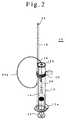
- Fig. 1 and Fig. 2show a whole structure of an injector of sperm of an ox for artificial insemination according to the present invention, in which Fig. 1 is an exploded perspective view and Fig. 2 is a perspective view showing an assembled semen injector of the present invention.
- an injector 10comprises a heat-retaining tube 12, a protecting cover 14 covering approximately half the outer periphery of the heat-retaining tube 12, a holder member 16 mounted to the lower front part of the protecting cover 14, an outer pipe 18, a rear part of which is fitted to the holder member 16, a pinch cock 20 which is fitted removably to outer peripheries of the heat-retaining tube 12 and the protecting cover 14 for fixing the outer pipe 18 to the holder member 16, a flexible tube 24 for semen injection, a front part of which is inserted into the outer pipe, a syringe 22, a hollow barrel of which is inserted into the rear end of the heat-retaining tube 12, and a semen straw 26, one end of which is connected to a front end of the syringe 22 and the other end of which is connected to the flexible tube 24 for semen injection.
- the heat-retaining tube 12is provided with a flange 12a at its rear end opening and in the front end of which a small hole 12b is perforated.
- the heat-retaining tube 12serves the two purposes of heat insulation and protection of the syringe 22 and the straw 26 which are contained therein.
- the heat-retaining tube 12is made from a transparent acrylic resin so that visual observation of the inside can be performed when the syringe 22 and the straw 26 are inserted therein.
- the protecting cover 14serves for the purposes of heat insulation and position maintenance of the outer pipe 18 and is formed in a half-round tube of a stainless steel sheet so as to fit to the outer periphery of the heat-retaining tube 12.
- the holder member 16is fixed integrally to the lower front part of the protecting cover 14 by welding. This holder member 16 has a half-rounded groove lengthwise over the whole length.
- the outer pipe 18is a hollow pipe made from stainless steel or the like and has a small outer diameter of approximately 3 mm so as to pass easily through a cervical canal and has a length of approximately 50cm while a part of which is omitted in Figs. 1 and 2.
- the semen injecting pipe 24is a flexible translucent hollow tube of TEFLON® or the like and is selected from such flexible materials that can advance smoothly in the forward direction from the front end of the outer pipe 18 when the tube 24 is pinched with fingers and pushed forward at the rear of the outer tube 18.
- the injecting nozzle 28is made from stainless steel and comprises a hollow tube part 28a fitted into the inner periphery of the front end of the tube 24 and a nozzle head 28b located at the front end of the tube part 28a.
- a base part at the lower end of the nozzle head 28bhas the same outer diameter as that of the outer pipe 18.
- the nozzle head 28bhas a hemispherically rounded front end and a pair of discharge openings 28c formed in the outer periphery of the nozzle head 28b oppositely at 180 degrees.
- the semen injecting tube 24is introduced from the aforementioned discharge nozzle 28 into the inside of the outer pipe 18 and goes out of the rear end of the outer pipe 18 to make approximately one turn there, and then is inserted from the small hole 12b of the front end of the heat-retaining tube 12 into the inside thereof, as shown in Fig. 2.
- the syringe 22has a function as a piston for pushing out semen in the straw 26. It is preferable that the syringe 22 contains a liquid drug such as dextrose liquid or the like containing an effective substance for maintaining the activity of sperm, whereby the liquid drug is pushed out from the aforementioned discharge nozzle together with the semen.
- a liquid drugsuch as dextrose liquid or the like containing an effective substance for maintaining the activity of sperm, whereby the liquid drug is pushed out from the aforementioned discharge nozzle together with the semen.
- the straw 26is a polyethylene-made tube, one end of which is sealed and the other end of which is blocked by a cotton plug and in which semen of an ox is conserved by freezing. Both ends are cut off after thawing the semen, which are then connected to the syringe 22 and the tube 24 through the sockets 30 and 32, respectively.
- Fig. 4shows the connection of the straw 26.
- each socket 30, 32is formed of high density polyethylene.
- One end of socket 30is a tapered-shape so as to adapt to the taper of the nozzle of the syringe 22a and the other end is a somewhat small tapered-shape which is enlarged outward corresponding to the outer diameter of the straw 26.
- One end of the other socket 32is fitted to the outer periphery of the straw 26 and is actually also a tapered-shape enlarged outwards as described above, but which is shown as a straight-shaped structure in Fig. 4.
- the diameter of the other endis previously set so as to fit fixedly to the inner diameter of the tube 24.
- the protecting cover 14is fitted to the lower surface of the heat-retaining tube 12 and the rear end portion of the outer pipe 18 is fitted to the holder member 16 of the protecting cover 14. Then, while maintaining the above fitting state by one hand, the pinch cock 20 is inserted with other hand from the front end of the outer pipe 18 and then the pinch cock 20 is moved to the outer surface of the aforementioned fitted three members while opening the pinchcock by pinching finger grips strongly. Thereafter, when the pinching force applied to the finger grips of the pinchcock is released, the outer pipe 18 is fixed to the heat-retaining tube 12 through the protecting cover 14 as shown in Fig. 2.
- Each outer peripheral surface of the heat-retaining tube 12 and the outer pipe 18is covered with a transparent plastic cover (bag) made of vinyl or the like in an assembled state so as to prevent contamination at initial stage of operation.
- a transparent plastic coverbag made of vinyl or the like in an assembled state so as to prevent contamination at initial stage of operation.
- the outer pipe 18is mounted to the heat-retaining tube 12 by using the pinchcock 20 in such a manner as described above.
- the semen injecting tube 24is made to occupy a retracted position so that the discharge nozzle 28 at the front end of the tube 24 can block the opening at the front end of the outer pipe 18.
- a setting operation for the injector 10is carried out according to the procedures as described below.
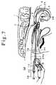
- Figs. 5 to 7are explanatory pictorial views of fertilization operation by a rectovaginal method using the injector 10 just after assembling in such a manner as described above.
- the aforementioned vinyl covers 34 and 36 covering the outer peripheries of the outer pipe 18 and the heat-retaining tube 12are shown in broken lines.
- one handis first inserted into the rectum 1 through the anus to grasp the cervical canal 2 through the rectum 1, then the outer pipe 18 of the semen injector 10 is inserted into the uterus by the other hand to pass through the cervical canal 2 while ascertaining a position of outer pipe 18 by feeling of the hand at a position of the cervical canal 2.
- the outer pipe 18When the outer pipe 18 has passed through the cervical canal 2, the outer pipe 18 is inserted further in about 5cm toward the cornu uteri 4 at the side of ovulation as shown in Fig. 6.
- the side of ovulation in one of two cornu uteri 4can be ascertained by touch on the ovarium by a hand.
- the nozzle head 28breaches the depths of the cornu uteri 4 while only softly touching the endometrium as shown in Fig. 7, because the specific gravity of the nozzle head 28 is considerably higher than that of the tube 24 as the nozzle head 28 is made from stainless steel, thereby curving the tube downward. While a rough measure of the length of the tube 24 paid out is 15 to 20cm for a parous cow and 10 to 15 cm for an unparous cow, it is adjusted depending on differences between the individual cows. The length of the tube 24 paid out can easily be identified by a mark printed on the tube.
- the syringe 10is disassembled as shown in Fig. 1 and is washed, sterilized and disinfected, thereby enabling reuse.
- the injector of the present inventionis applied to artificial insemination of a cow is described in the aforementioned preferred embodiments, the preferred embodiments are available for transplantation of an ovum of a cow in the same manner. And they are available not only for a cow, but also for animals such as horses and any others to which a rectovaginal method can be applied.
- the injector of the present inventionis not limited to the aforementioned preferred embodiments, but may be made in various kinds of modifications, for example, the syringe may be constructed of a capsule-shaped transparent or translucent plastic container 40 comprising a body and a neck as shown in Fig. 9. It is possible that the liquid drug 41 containing effective substances such as dextrose liquid for activation of a sperm or of an ovum is previously injected in the body of the plastic container 40 and the front end 42 of the neck is crushed flat to form the airtight seal, and the front end of the neck is cut off in use so that the straw is mounted through the socket 30 as shown in the aforementioned preferred embodiments. While this plastic container 40 is preferably selected from plastic deformable materials such as celluloid and the like, it is necessary that a member is mounted for maintaining the deformed state so as not to return to the original state after elastic deformation when using an elastic deformable plastic.
- the flexible tubeSince the flexible tube is inserted directly through the inside of the outer pipe, the outer diameter of the outer tube can be diminished so that it can be easily inserted without injuring the cervical canal. Also, since the flexible tube paid out forward from the outer pipe bends downward owing to the weight of the nozzle body of its front end, it goes surely into a cornu uteri and thereafter is inserted into the depths of the cornu uteri along a curve of the cornu uteri. Comparing the injector of the present invention with a conventional sperm injector, it has been ascertained that the good results of insemination according to the invention can be obtained even if the number of sperm is one 200th of that conventionally used.
- the operationis carried out in air of relatively low temperature, the inactivation of the sperm or ovum by temperature shock can be prevented.
- the heat-retaining tubeis made from transparent materials, the pushing through of the sperm or ovum through the inside of the transparent or translucent tube by means of a pushing means can be visually observed. Also, since the tube goes out of the rear end of the outer pipe and makes approximately one turn, the operation of paying out the tube into the outer pipe by pinching this portion with fingertips can be easily carried out.
- the length of surplus portion of this tube making one turnis matched with the length of the tube paid out from the front end of the outer tube, the length of the tube which is to be paid out can be easily grasped. Furthermore, if a scale is marked to the surplus portion of the tube, the length of the tube paid out can be more easily ascertained.
- the situation in which the sperm or ovum is pushed in the tubecan be visually observed by making the tube from transparent or translucent material.
- the injector of the present inventioncan be fitted to the straw of various diameters without changing other parts of the injector.
- the insemination rate or embryogeny ratecan be improved.
Landscapes
- Life Sciences & Earth Sciences (AREA)
- Health & Medical Sciences (AREA)
- Veterinary Medicine (AREA)
- Wood Science & Technology (AREA)
- Engineering & Computer Science (AREA)
- Reproductive Health (AREA)
- Animal Husbandry (AREA)
- Zoology (AREA)
- Animal Behavior & Ethology (AREA)
- General Health & Medical Sciences (AREA)
- Public Health (AREA)
- Media Introduction/Drainage Providing Device (AREA)
- Surgical Instruments (AREA)
- External Artificial Organs (AREA)
Abstract
Description
Claims (9)
- An injector (10) of sperm for artificial insemination or of afertilized ovum for transplantation of a domestic animal comprising an outerpipe (18), a flexible tube (24) inserted and placed inside of said outer pipeto be freely pushed out, a nozzle body (28) mounted integrally to a frontend of said flexible tube, said nozzle body having a closed front end whichis formed in the shape of a spherical surface arid having a rear end connectedto said flexible tube, said nozzle body further having in a side of said nozzlea perforated hole (28c) connected to said flexible tube, and a pushing means(22) adapted to be connected with a rear end of said flexible tube for sendingforward the sperm or ovum, said flexible tube being pushed forward from therear end of said outer pipe after insertion of said outer pipe into the corpusuteri of a domestic animal, thereby sending out said flexible tube forwardfrom the front end of said outer pipe to send said nozzle body to a deep portionof a cornu uteri and thereafter to discharge the spermorovum from said perforatedhole of said nozzle body into the deep portion of said cornu uteri from theinside of said flexible tube by said pushing means.
- An injector of sperm for artificial insemination or of a fertilizedovum for transplantation of a domestic animal as claimed in claim 1, whereinsaid flexible tube extends outside beyond the rear end of said outer pipe,the extended part of said flexible tube is able to be pinched by finger tipsand pushed forward by said finger tips.
- An injector of sperm for artificial insemination or of a fertilizedovum for transplantation of a domestic animal as claimed in claim 2, whereina heat-retaining tube (12) is fitted to an outer peripheral surface of therear end of said outer pipe, and the rear end of said flexible tube extends rearward from the rear end of said outer pipe and goes into said heat-retainingtube from the front end of said heat-retaining tube by making approximatelyone turn between said outer pipe and said heat-retaining tube.
- An injector of sperm for artificial insemination or of a fertilizedovum for transplantation of a domestic animal as claimed in claim 3, whereinsaid one turn of said flexible tube defines a length of the flexible tubeto be paid out from the front end of said outer pipe, said length of saidflexible tube corresponding to the distance from the inside of the cervicalcanal to the deep portion of the cornu uteri.
- An injector of sperm for artificial insemination or of a fertilizedovum for transplantation of a domestic animal as claimed in claim 3, comprisinga straw (26) containing sperm or ovum and removably attached between the rearend of said flexible tube and said pushing means to be contained in saidheat-retaining tube.
- An injector of sperm for artificial insemination or of a fertilizedovum for transplantation of a domestic animal as claimed in claim 3, whereinsaid heat-retaining tube is made from a transparent material.
- An injector of sperm for artificial insemination or of a fertilizedovum for transplantation of a domestic animal as claimed in claim 5, whereinsocket members (30, 32) adaptable to straws of different calibers is mountedremovably to the front end and rear end of said straw respectively, and saidstraw is joined to said flexible tube and said pushing means respectivelythrough each of said socket member.
- An injector of sperm for artificial insemination or of a fertilizedovum for transplantation of a domestic animal as claimed in claim 1, whereinan effective substance for maintaining activity of sperm or an ovum ispreviously injected into said pushing means before said straw is joined.
- A method of operating an injector as claimed in claim 3, whereinan outer periphery of said outer pipe is covered with a first plastic bag(34) which is watertight, transparent and thin and the front end of whichis sealed, an outer periphery of said heat-retaining tube is covered witha second plastic bag (36) which is watertight, transparent and thin and therear end of which is sealed, and said outer pipe of a given length said injectoris inserted into the uterus of a domestic animal so that an overlapping portionof both transparent plastic bags is sealed through a banding means, then saidfirst plastic bag is moved relatively to said outer pipe to break a sealedportion of the front end of said first plastic bag, thereafter said flexibletube is picked with fingertips from outside of said second plastic bag, therebypushing to send forward said flexible tube.
Applications Claiming Priority (2)
| Application Number | Priority Date | Filing Date | Title |
|---|---|---|---|
| JP19596999AJP3361778B2 (en) | 1999-07-09 | 1999-07-09 | Injector for sperm for artificial insemination or fertilized egg transplantation of livestock and method of operating the same |
| JP19596999 | 1999-07-09 |
Publications (3)
| Publication Number | Publication Date |
|---|---|
| EP1066802A2true EP1066802A2 (en) | 2001-01-10 |
| EP1066802A3 EP1066802A3 (en) | 2002-06-12 |
| EP1066802B1 EP1066802B1 (en) | 2006-08-30 |
Family
ID=16350016
Family Applications (1)
| Application Number | Title | Priority Date | Filing Date |
|---|---|---|---|
| EP00305031AExpired - LifetimeEP1066802B1 (en) | 1999-07-09 | 2000-06-14 | Injector of sperm or of a fertilized ovum into a domestic animal |
Country Status (5)
| Country | Link |
|---|---|
| US (1) | US6454756B1 (en) |
| EP (1) | EP1066802B1 (en) |
| JP (1) | JP3361778B2 (en) |
| AT (1) | ATE337753T1 (en) |
| DE (1) | DE60030361T2 (en) |
Cited By (11)
| Publication number | Priority date | Publication date | Assignee | Title |
|---|---|---|---|---|
| WO2003094777A1 (en)* | 2002-05-10 | 2003-11-20 | Continental Plastic Corp. | Dual use syringe |
| US7837611B2 (en) | 2006-04-28 | 2010-11-23 | Ainley Jr Frank | Animal insemination sheath apparatus |
| US8323178B2 (en) | 2006-04-28 | 2012-12-04 | Ainley Jr Frank | Animal insemination sheath and methods of use |
| US9433484B2 (en) | 2007-07-27 | 2016-09-06 | Brad K. Stroud | Artificial breeding techniques for bovines including semen diluents and AI apparatus |
| CN106344132A (en)* | 2016-10-09 | 2017-01-25 | 上海市第妇婴保健院 | Embryo transplantation tube |
| US10182896B2 (en) | 2016-03-08 | 2019-01-22 | Frank Ainley | Animal insemination sheath and methods of use |
| WO2019170951A1 (en)* | 2018-03-07 | 2019-09-12 | Universidad de Córdoba | Flexible device for freezing semen doses |
| US10610343B2 (en) | 2013-07-03 | 2020-04-07 | Brad K. Stroud | Method, apparatus and kit for artificial insemination of bovine |
| US11103336B2 (en) | 2016-03-08 | 2021-08-31 | Frank Ainley | Animal insemination and in-vitro fertilization sheath, cap and methods of use |
| US11622844B2 (en) | 2010-08-10 | 2023-04-11 | Maximate, Llc | Method, apparatus and kit for artificial insemination of bovine |
| CN119837614A (en)* | 2025-03-19 | 2025-04-18 | 内蒙古医科大学附属医院(内蒙古自治区心血管研究所) | Embryo transplanting device for test tube infant |
Families Citing this family (17)
| Publication number | Priority date | Publication date | Assignee | Title |
|---|---|---|---|---|
| NZ550196A (en)* | 2004-03-29 | 2010-11-26 | Inguran Llc | Method for sorting sperm cells into X or Y chromosome-bearing enriched populations comprising a composition which inhibits motility and a DNA-selective dye |
| US20060271014A1 (en)* | 2005-05-31 | 2006-11-30 | Mallinckrodt Inc. | Heat retention device for a syringe and methods of use |
| US8202210B2 (en)* | 2007-07-27 | 2012-06-19 | Stroud Brad K | Artificial breeding techniques for bovines including semen diluents and AI apparatus |
| US20100331610A1 (en)* | 2009-06-26 | 2010-12-30 | Sheng-Jui Chen | Artificial insemination device for animals |
| WO2012021127A2 (en) | 2010-08-10 | 2012-02-16 | Stroud Brad R | Method and apparatus to reduce the number of sperm used in artificial insemination of cattle |
| JP6218165B2 (en) | 2012-05-22 | 2017-10-25 | 株式会社ヤマネテック | Fertilized egg / sperm injector |
| KR101326200B1 (en) | 2013-10-07 | 2013-11-20 | 정덕수 | The device for artificial insemination |
| CN103932817B (en)* | 2014-04-16 | 2015-11-18 | 内蒙古赛科星繁育生物技术(集团)股份有限公司 | The multi-functional spermatic gun of intelligent milch cow/beef cattle |
| KR101757161B1 (en)* | 2015-09-04 | 2017-07-14 | 주식회사 지엠엠씨 | Deep insemination catheters for artificial insemination of domestic animals |
| JP6263219B2 (en)* | 2016-03-30 | 2018-01-17 | エア・ウォーター・マッハ株式会社 | Injector |
| JP3205250U (en)* | 2016-05-02 | 2016-07-14 | 株式会社オンリースタイル | Semen injection tool and semen injection catheter |
| EP3528745B1 (en)* | 2016-10-18 | 2020-07-29 | Smartbow GmbH | Device for artificially inseminating a mammal |
| DK179517B1 (en)* | 2017-05-11 | 2019-02-05 | Mbh-International A/S | An artificial insemination device and a method of performing artificial insemination using the device |
| EP3687416A1 (en) | 2017-09-29 | 2020-08-05 | Nanovare SAS | Devices and methods for analysis of male infertility |
| JP7034876B2 (en)* | 2018-10-01 | 2022-03-14 | 耕生 水野 | Dropper function addition tool for straws |
| FR3129077B1 (en)* | 2021-11-18 | 2025-04-11 | Landata Cobiporc | Device for artificial insemination of farm animals |
| CN115153784A (en)* | 2022-07-19 | 2022-10-11 | 太平洋康泰科学仪器(济南)有限公司 | Embryo transfer tube, transfer assembly and use method |
Family Cites Families (15)
| Publication number | Priority date | Publication date | Assignee | Title |
|---|---|---|---|---|
| US3877464A (en)* | 1972-06-07 | 1975-04-15 | Andrew R Vermes | Intra-uterine biopsy apparatus |
| US4416660A (en)* | 1975-07-09 | 1983-11-22 | Dafoe Charles A | Method of transvaginal sterilization |
| US4637818A (en)* | 1983-11-25 | 1987-01-20 | Johnson Richard K | Apparatus for producing sterility in female animals |
| JPS6136935A (en) | 1984-07-30 | 1986-02-21 | Matsushita Electronics Corp | Manufacture of semiconductor device |
| US4574000A (en)* | 1984-08-24 | 1986-03-04 | Hunter Stephen K | Artificial fallopian tube |
| FR2575063B1 (en)* | 1984-12-21 | 1988-07-01 | Cassou Robert | GYNECOLOGICAL PROBE FOR ARTIFICIAL INSEMINATION, ESPECIALLY FOR SWINE |
| JPS62107819A (en) | 1985-11-05 | 1987-05-19 | Kawasaki Steel Corp | Production of amorphous alloy wire |
| FR2608037A1 (en)* | 1986-12-10 | 1988-06-17 | Lenck Lucien | INTUBATION METHOD FOR PERMITTING THE TRANSPLANTATION OF EGG OR EMBRYONIC MATTER, AND MEANS FOR IMPLEMENTING THE SAME |
| US5005583A (en)* | 1987-07-22 | 1991-04-09 | Research & Education Institute, Inc. Harbor-Ucla Medical Center | Diagnostics procedures in unexplained female infertility |
| US5147315A (en)* | 1990-04-06 | 1992-09-15 | C. R. Bard, Inc. | Access catheter and system for use in the female reproductive system |
| US5108366A (en)* | 1990-09-28 | 1992-04-28 | Ovamed Corporation | Delivery catheter |
| US5904665A (en)* | 1995-03-07 | 1999-05-18 | Vance Products Inc. | Automated prolonged slow release intrauterine insemination using self retaining intrauterine insemination catheter |
| DE29706541U1 (en)* | 1997-04-11 | 1997-06-19 | Chou, Chia-Le, Hsin Shih Hsiang, Tainan | Improvement of the artificial insemination injector for sow |
| US6033413A (en)* | 1998-04-20 | 2000-03-07 | Endocare, Inc. | Stent delivery system |
| US6146378A (en)* | 1999-03-19 | 2000-11-14 | Endocare, Inc. | Placement guide for ablation devices |
- 1999
- 1999-07-09JPJP19596999Apatent/JP3361778B2/ennot_activeExpired - Lifetime
- 2000
- 2000-05-24USUS09/578,193patent/US6454756B1/ennot_activeExpired - Lifetime
- 2000-06-14EPEP00305031Apatent/EP1066802B1/ennot_activeExpired - Lifetime
- 2000-06-14ATAT00305031Tpatent/ATE337753T1/ennot_activeIP Right Cessation
- 2000-06-14DEDE60030361Tpatent/DE60030361T2/ennot_activeExpired - Fee Related
Non-Patent Citations (1)
| Title |
|---|
| None |
Cited By (13)
| Publication number | Priority date | Publication date | Assignee | Title |
|---|---|---|---|---|
| WO2003094777A1 (en)* | 2002-05-10 | 2003-11-20 | Continental Plastic Corp. | Dual use syringe |
| US7241261B2 (en) | 2002-05-10 | 2007-07-10 | Continental Plastic Corp. | Dual use syringe |
| US7837611B2 (en) | 2006-04-28 | 2010-11-23 | Ainley Jr Frank | Animal insemination sheath apparatus |
| US8323178B2 (en) | 2006-04-28 | 2012-12-04 | Ainley Jr Frank | Animal insemination sheath and methods of use |
| US9433484B2 (en) | 2007-07-27 | 2016-09-06 | Brad K. Stroud | Artificial breeding techniques for bovines including semen diluents and AI apparatus |
| US11622844B2 (en) | 2010-08-10 | 2023-04-11 | Maximate, Llc | Method, apparatus and kit for artificial insemination of bovine |
| US10610343B2 (en) | 2013-07-03 | 2020-04-07 | Brad K. Stroud | Method, apparatus and kit for artificial insemination of bovine |
| US10182896B2 (en) | 2016-03-08 | 2019-01-22 | Frank Ainley | Animal insemination sheath and methods of use |
| US11103336B2 (en) | 2016-03-08 | 2021-08-31 | Frank Ainley | Animal insemination and in-vitro fertilization sheath, cap and methods of use |
| CN106344132B (en)* | 2016-10-09 | 2018-12-07 | 上海市第一妇婴保健院 | an embryo transfer tube |
| CN106344132A (en)* | 2016-10-09 | 2017-01-25 | 上海市第妇婴保健院 | Embryo transplantation tube |
| WO2019170951A1 (en)* | 2018-03-07 | 2019-09-12 | Universidad de Córdoba | Flexible device for freezing semen doses |
| CN119837614A (en)* | 2025-03-19 | 2025-04-18 | 内蒙古医科大学附属医院(内蒙古自治区心血管研究所) | Embryo transplanting device for test tube infant |
Also Published As
| Publication number | Publication date |
|---|---|
| EP1066802A3 (en) | 2002-06-12 |
| ATE337753T1 (en) | 2006-09-15 |
| EP1066802B1 (en) | 2006-08-30 |
| JP2001017026A (en) | 2001-01-23 |
| DE60030361T2 (en) | 2007-09-13 |
| JP3361778B2 (en) | 2003-01-07 |
| US6454756B1 (en) | 2002-09-24 |
| DE60030361D1 (en) | 2006-10-12 |
Similar Documents
| Publication | Publication Date | Title |
|---|---|---|
| EP1066802B1 (en) | Injector of sperm or of a fertilized ovum into a domestic animal | |
| US7056279B2 (en) | Device and method for artificial insemination of bovines and other animals | |
| US7419465B2 (en) | Animal insemination sheath-methods of use | |
| AU713345B2 (en) | A system for introducing a fluid into the uterus of an animal | |
| US5899848A (en) | Device and process for artificial insemination of animals | |
| US4846785A (en) | Instrument for artificial insemination, embryo transfer or sampling follicular liquids in mammals | |
| CA2449991C (en) | Device for sow intra-uterine insemination and embryo transfer | |
| JPH08501718A (en) | Artificial fertilization and fertilized egg transfer device | |
| US6605034B2 (en) | Device for protecting a cover, the use of a device for protecting a cover, a method of fitting a cover on a probe, and a method of making a device for protecting a cover | |
| US5656010A (en) | System for effecting embryo transplant | |
| US8323178B2 (en) | Animal insemination sheath and methods of use | |
| US5558636A (en) | Method of effecting embryo transplant | |
| US20040162461A1 (en) | Apparatus for trans-cervical artificial insemination and embryo transfer | |
| US20020038113A1 (en) | Apparatus and method for artificial insemination and embryo transfer of animals | |
| US6607518B1 (en) | Assembly and method for penetrating the uterus of an animal during a non-surgical procedure | |
| EP1411814B1 (en) | Device for trans-cervical artificial insemination and embryo transfer | |
| KR101757161B1 (en) | Deep insemination catheters for artificial insemination of domestic animals | |
| JP2859364B2 (en) | Fertilized egg transplantation device | |
| US10182896B2 (en) | Animal insemination sheath and methods of use | |
| JP4769913B2 (en) | Deep injector for transplantation of livestock embryos | |
| US11103336B2 (en) | Animal insemination and in-vitro fertilization sheath, cap and methods of use | |
| JPH0412971Y2 (en) | ||
| CN119548286A (en) | Intrauterine continuous insemination device for livestock | |
| JPH0741458Y2 (en) | Egg collector | |
| JPH0511917U (en) | Fertilized egg deep transplanter for livestock |
Legal Events
| Date | Code | Title | Description |
|---|---|---|---|
| PUAI | Public reference made under article 153(3) epc to a published international application that has entered the european phase | Free format text:ORIGINAL CODE: 0009012 | |
| AK | Designated contracting states | Kind code of ref document:A2 Designated state(s):AT BE CH CY DE DK ES FI FR GB GR IE IT LI LU MC NL PT SE | |
| AX | Request for extension of the european patent | Free format text:AL;LT;LV;MK;RO;SI | |
| PUAL | Search report despatched | Free format text:ORIGINAL CODE: 0009013 | |
| AK | Designated contracting states | Kind code of ref document:A3 Designated state(s):AT BE CH CY DE DK ES FI FR GB GR IE IT LI LU MC NL PT SE | |
| AX | Request for extension of the european patent | Free format text:AL;LT;LV;MK;RO;SI | |
| RIC1 | Information provided on ipc code assigned before grant | Free format text:7A 61C 19/02 A, 7A 61D 19/02 B | |
| 17P | Request for examination filed | Effective date:20021211 | |
| AKX | Designation fees paid | Designated state(s):AT BE CH CY DE DK ES FI FR GB GR IE IT LI LU MC NL PT SE | |
| 17Q | First examination report despatched | Effective date:20040708 | |
| GRAP | Despatch of communication of intention to grant a patent | Free format text:ORIGINAL CODE: EPIDOSNIGR1 | |
| RTI1 | Title (correction) | Free format text:INJECTOR OF SPERM OR OF A FERTILIZED OVUM INTO A DOMESTIC ANIMAL | |
| GRAS | Grant fee paid | Free format text:ORIGINAL CODE: EPIDOSNIGR3 | |
| GRAA | (expected) grant | Free format text:ORIGINAL CODE: 0009210 | |
| AK | Designated contracting states | Kind code of ref document:B1 Designated state(s):AT BE CH CY DE DK ES FI FR GB GR IE IT LI LU MC NL PT SE | |
| PG25 | Lapsed in a contracting state [announced via postgrant information from national office to epo] | Ref country code:IT Free format text:LAPSE BECAUSE OF FAILURE TO SUBMIT A TRANSLATION OF THE DESCRIPTION OR TO PAY THE FEE WITHIN THE PRESCRIBED TIME-LIMIT;WARNING: LAPSES OF ITALIAN PATENTS WITH EFFECTIVE DATE BEFORE 2007 MAY HAVE OCCURRED AT ANY TIME BEFORE 2007. THE CORRECT EFFECTIVE DATE MAY BE DIFFERENT FROM THE ONE RECORDED. Effective date:20060830 Ref country code:LI Free format text:LAPSE BECAUSE OF FAILURE TO SUBMIT A TRANSLATION OF THE DESCRIPTION OR TO PAY THE FEE WITHIN THE PRESCRIBED TIME-LIMIT Effective date:20060830 Ref country code:NL Free format text:LAPSE BECAUSE OF FAILURE TO SUBMIT A TRANSLATION OF THE DESCRIPTION OR TO PAY THE FEE WITHIN THE PRESCRIBED TIME-LIMIT Effective date:20060830 Ref country code:CH Free format text:LAPSE BECAUSE OF FAILURE TO SUBMIT A TRANSLATION OF THE DESCRIPTION OR TO PAY THE FEE WITHIN THE PRESCRIBED TIME-LIMIT Effective date:20060830 Ref country code:AT Free format text:LAPSE BECAUSE OF FAILURE TO SUBMIT A TRANSLATION OF THE DESCRIPTION OR TO PAY THE FEE WITHIN THE PRESCRIBED TIME-LIMIT Effective date:20060830 Ref country code:FI Free format text:LAPSE BECAUSE OF FAILURE TO SUBMIT A TRANSLATION OF THE DESCRIPTION OR TO PAY THE FEE WITHIN THE PRESCRIBED TIME-LIMIT Effective date:20060830 Ref country code:BE Free format text:LAPSE BECAUSE OF FAILURE TO SUBMIT A TRANSLATION OF THE DESCRIPTION OR TO PAY THE FEE WITHIN THE PRESCRIBED TIME-LIMIT Effective date:20060830 | |
| REG | Reference to a national code | Ref country code:GB Ref legal event code:FG4D | |
| REG | Reference to a national code | Ref country code:CH Ref legal event code:EP | |
| REG | Reference to a national code | Ref country code:IE Ref legal event code:FG4D | |
| REF | Corresponds to: | Ref document number:60030361 Country of ref document:DE Date of ref document:20061012 Kind code of ref document:P | |
| PG25 | Lapsed in a contracting state [announced via postgrant information from national office to epo] | Ref country code:DK Free format text:LAPSE BECAUSE OF FAILURE TO SUBMIT A TRANSLATION OF THE DESCRIPTION OR TO PAY THE FEE WITHIN THE PRESCRIBED TIME-LIMIT Effective date:20061130 Ref country code:SE Free format text:LAPSE BECAUSE OF FAILURE TO SUBMIT A TRANSLATION OF THE DESCRIPTION OR TO PAY THE FEE WITHIN THE PRESCRIBED TIME-LIMIT Effective date:20061130 | |
| PG25 | Lapsed in a contracting state [announced via postgrant information from national office to epo] | Ref country code:ES Free format text:LAPSE BECAUSE OF FAILURE TO SUBMIT A TRANSLATION OF THE DESCRIPTION OR TO PAY THE FEE WITHIN THE PRESCRIBED TIME-LIMIT Effective date:20061211 | |
| PG25 | Lapsed in a contracting state [announced via postgrant information from national office to epo] | Ref country code:PT Free format text:LAPSE BECAUSE OF FAILURE TO SUBMIT A TRANSLATION OF THE DESCRIPTION OR TO PAY THE FEE WITHIN THE PRESCRIBED TIME-LIMIT Effective date:20070206 | |
| REG | Reference to a national code | Ref country code:CH Ref legal event code:PL | |
| NLV1 | Nl: lapsed or annulled due to failure to fulfill the requirements of art. 29p and 29m of the patents act | ||
| ET | Fr: translation filed | ||
| PLBE | No opposition filed within time limit | Free format text:ORIGINAL CODE: 0009261 | |
| STAA | Information on the status of an ep patent application or granted ep patent | Free format text:STATUS: NO OPPOSITION FILED WITHIN TIME LIMIT | |
| 26N | No opposition filed | Effective date:20070531 | |
| PG25 | Lapsed in a contracting state [announced via postgrant information from national office to epo] | Ref country code:MC Free format text:LAPSE BECAUSE OF NON-PAYMENT OF DUE FEES Effective date:20070630 | |
| PG25 | Lapsed in a contracting state [announced via postgrant information from national office to epo] | Ref country code:GR Free format text:LAPSE BECAUSE OF FAILURE TO SUBMIT A TRANSLATION OF THE DESCRIPTION OR TO PAY THE FEE WITHIN THE PRESCRIBED TIME-LIMIT Effective date:20061201 | |
| PG25 | Lapsed in a contracting state [announced via postgrant information from national office to epo] | Ref country code:IE Free format text:LAPSE BECAUSE OF NON-PAYMENT OF DUE FEES Effective date:20070614 | |
| PG25 | Lapsed in a contracting state [announced via postgrant information from national office to epo] | Ref country code:CY Free format text:LAPSE BECAUSE OF FAILURE TO SUBMIT A TRANSLATION OF THE DESCRIPTION OR TO PAY THE FEE WITHIN THE PRESCRIBED TIME-LIMIT Effective date:20060830 Ref country code:LU Free format text:LAPSE BECAUSE OF NON-PAYMENT OF DUE FEES Effective date:20070614 | |
| PGFP | Annual fee paid to national office [announced via postgrant information from national office to epo] | Ref country code:GB Payment date:20090610 Year of fee payment:10 Ref country code:DE Payment date:20090615 Year of fee payment:10 | |
| GBPC | Gb: european patent ceased through non-payment of renewal fee | Effective date:20100614 | |
| REG | Reference to a national code | Ref country code:FR Ref legal event code:ST Effective date:20110228 | |
| PG25 | Lapsed in a contracting state [announced via postgrant information from national office to epo] | Ref country code:DE Free format text:LAPSE BECAUSE OF NON-PAYMENT OF DUE FEES Effective date:20110101 | |
| PG25 | Lapsed in a contracting state [announced via postgrant information from national office to epo] | Ref country code:FR Free format text:LAPSE BECAUSE OF NON-PAYMENT OF DUE FEES Effective date:20100630 | |
| PG25 | Lapsed in a contracting state [announced via postgrant information from national office to epo] | Ref country code:GB Free format text:LAPSE BECAUSE OF NON-PAYMENT OF DUE FEES Effective date:20100614 | |
| PGFP | Annual fee paid to national office [announced via postgrant information from national office to epo] | Ref country code:FR Payment date:20090611 Year of fee payment:10 |