EP1065380B1 - DC-Motor control circuit for a diaphragm pump - Google Patents
DC-Motor control circuit for a diaphragm pumpDownload PDFInfo
- Publication number
- EP1065380B1 EP1065380B1EP99112608AEP99112608AEP1065380B1EP 1065380 B1EP1065380 B1EP 1065380B1EP 99112608 AEP99112608 AEP 99112608AEP 99112608 AEP99112608 AEP 99112608AEP 1065380 B1EP1065380 B1EP 1065380B1
- Authority
- EP
- European Patent Office
- Prior art keywords
- motor
- pulse
- voltage
- diaphragm pump
- control device
- Prior art date
- Legal status (The legal status is an assumption and is not a legal conclusion. Google has not performed a legal analysis and makes no representation as to the accuracy of the status listed.)
- Expired - Lifetime
Links
- 102100039435C-X-C motif chemokine 17Human genes0.000claimsdescription5
- 101000889048Homo sapiens C-X-C motif chemokine 17Proteins0.000claimsdescription5
- 230000001276controlling effectEffects0.000description11
- 238000005086pumpingMethods0.000description8
- 230000001105regulatory effectEffects0.000description6
- 239000012530fluidSubstances0.000description5
- 230000008878couplingEffects0.000description4
- 238000010168coupling processMethods0.000description4
- 238000005859coupling reactionMethods0.000description4
- 239000000645desinfectantSubstances0.000description4
- 239000007788liquidSubstances0.000description4
- XUIMIQQOPSSXEZ-UHFFFAOYSA-NSiliconChemical compound[Si]XUIMIQQOPSSXEZ-UHFFFAOYSA-N0.000description3
- 230000000630rising effectEffects0.000description3
- 229910052710siliconInorganic materials0.000description3
- 239000010703siliconSubstances0.000description3
- XLYOFNOQVPJJNP-UHFFFAOYSA-NwaterSubstancesOXLYOFNOQVPJJNP-UHFFFAOYSA-N0.000description3
- OKTJSMMVPCPJKN-UHFFFAOYSA-NCarbonChemical compound[C]OKTJSMMVPCPJKN-UHFFFAOYSA-N0.000description2
- 230000036772blood pressureEffects0.000description2
- 229910052799carbonInorganic materials0.000description2
- 238000002347injectionMethods0.000description2
- 239000007924injectionSubstances0.000description2
- 230000001419dependent effectEffects0.000description1
- 238000010586diagramMethods0.000description1
- 238000012986modificationMethods0.000description1
- 230000004048modificationEffects0.000description1
- VIKNJXKGJWUCNN-XGXHKTLJSA-NnorethisteroneChemical compoundO=C1CC[C@@H]2[C@H]3CC[C@](C)([C@](CC4)(O)C#C)[C@@H]4[C@@H]3CCC2=C1VIKNJXKGJWUCNN-XGXHKTLJSA-N0.000description1
- 239000003973paintSubstances0.000description1
- 238000005507sprayingMethods0.000description1
Images


Classifications
- F—MECHANICAL ENGINEERING; LIGHTING; HEATING; WEAPONS; BLASTING
- F04—POSITIVE - DISPLACEMENT MACHINES FOR LIQUIDS; PUMPS FOR LIQUIDS OR ELASTIC FLUIDS
- F04B—POSITIVE-DISPLACEMENT MACHINES FOR LIQUIDS; PUMPS
- F04B43/00—Machines, pumps, or pumping installations having flexible working members
- F04B43/02—Machines, pumps, or pumping installations having flexible working members having plate-like flexible members, e.g. diaphragms
- F04B43/04—Pumps having electric drive
- F—MECHANICAL ENGINEERING; LIGHTING; HEATING; WEAPONS; BLASTING
- F04—POSITIVE - DISPLACEMENT MACHINES FOR LIQUIDS; PUMPS FOR LIQUIDS OR ELASTIC FLUIDS
- F04B—POSITIVE-DISPLACEMENT MACHINES FOR LIQUIDS; PUMPS
- F04B49/00—Control, e.g. of pump delivery, or pump pressure of, or safety measures for, machines, pumps, or pumping installations, not otherwise provided for, or of interest apart from, groups F04B1/00 - F04B47/00
- F04B49/06—Control using electricity
Definitions
- the present inventionrelates to a control device for a DC motor with a brush commutator for driving a crankshaft of a diaphragm pump, and particularly for controlling discharge of a DC motor driven diaphragm pump which is used as a metering injection pump.
- EP-A-0 363 672discloses that in a blood pressure monitor a blood pressure cuff is inflated by a pump driven by an electric motor.
- a control circuitcalculates the rate of inflation of said cuff over a predetermined period, compares said rate to a desired rate and generates a control signal to adjust the current supply of said motor to control the inflation rate.
- the motor speedis controlled by the adjustment of the duty cycle of the voltage applied to said motor.
- US-A-4 547 680discloses a diaphragm pump wherein the diaphragm is deformable by the reciprocable armature of an electromagnet which is energizable at a selected frequency by a timer circuit and at random frequency by a pulse generator.
- the pulse generatoris connectable with the electromagnet by a cable having separable male and female coupling elements which automatically deactivate the timer circuit when the male coupling element is inserted into the female coupling element.
- a selector switchis provided to deactivate the timer circuit independently of the coupling elements.
- a knobserves to adjust a potentiometer of the timer circuit simultaneously with closing of the selector switch so that the frequency at which the timer circuit can energize the electromagnet is reduced to a minimum value.
- US-A-4,397,610discloses a reciprocable liquid pump driven by a direct current electric motor wherein the motor drive voltage, and thereby pump reciprocation, and output pressure, is selectively controlled by a circuit including an electromechanical transducer coupled in pressure sensing relation to the liquid pump output, a manually operable pressure set point switch, and a silicon-controlled rectifier circuit.
- the documentis directed to improvements in pressure regulation and control for pumping systems, preferably pumping systems adapted for portable paint spraying equipment, wherein the pressure fluctuation range may be reduced by at least an order of magnitude from prior art systems.
- the apparatusincludes a direct current (DC) motor mechanically coupled in driving relationship to a reciprocable pump, wherein the pump output pressure is monitored by an electromechanical sensing device which delivers a voltage signal proportional to pump output pressure.
- the voltage signalis connected to an electronic circuit which has as another input a manual voltage setting for adjusting a setpoint pressure, the setpoint signal and pressure signal being compared and the difference between the two signals generating an error drive signal which is amplified and compared against a DC voltage reference and a timing signal.
- the combination of the timing signal and the error drive signalis used to develop a gating signal over a portion of the timing signal period.
- the gating signalis fed into a silicon controlled rectifier (SCR) circuit for controlling the gating time of the silicon controlled rectifier circuit so as to regulate the DC drive voltage into the motor.
- SCRsilicon controlled rectifier
- a DC drive signalis coupled into the motor to provide a DC drive voltage of sufficient magnitude to reciprocate the pump and thereby incrementally increase the pump output pressure to the set point value.
- a electric motor driven diaphragm pumphas been shown in the prior art.
- a electric motor used as driving device for a diaphragm pumpis commonly a stepping motor or a DC motor (Direct Current motor).
- discharge of the pumpis controlled by means of controlling a rotation speed of the stepping motor by modifying frequency or duty ratio of applied pulses to the stepping motor.
- discharge of the pumpis accurately regulated by the stepping motor, as shown in Fig. 7 depending on the duty ratio of pulses, discharge of the pump is so largely changed that is not applicable to a diaphragm pump for small amount metering.
- a stepping motor and a pulse frequency modulating device or a pulse duty control deviceare expensive and the weight of these devices are heavy.
- the relationship between a rotation speed of a stepping motor and discharge of a diaphragm pumpis illustrated in the case of setting a pulse width(PW1) at 40ms, 100ms and 200ms.
- the DC motorIn the case of using a DC motor for driving a diaphragm pump, the DC motor is applied direct current at a constant voltage to be rotated at constant speed, thereby the diaphragm pump discharges continuously constant amount of fluid.
- a flow control valveis required to be provided in a line after the discharge port of the diaphragm pump for metering a amount of fluid.
- the temperature of the motorbecomes high as shown on the curve A in Fig. 6.
- the curve Aillustrates the changing temperature of a DC motor when it runs at 3,600 rpm (applied 2V DC).
- Another controlling device for a DC motor as an actuator of a diaphragm pumpis to regulate rotating amount of the DC motor by application of pulses.
- a DC motorrotates intermittently and pumping pressure of a diaphragm pump is controlled by varying applied pulse voltage, and discharge per pumping cycle is regulated by modulating the duty ratio of applied pulses.
- the curve Bshows temperature of a DC motor in this case, the temperature of the motor is not so high but an overshoot at rising and falling period of a pulse (as shown in Fig. 6B) is repeatedly impressed to the DC motor, generating a spark at the commutator of the motor and deposit carbon in a brush contact surface of a commutator. This results in a reduction of the service life of the DC motor.
- Another object of the present inventionis to provide a controlling device for a DC motor for driving a diaphragm pump, which applies pulses to the DC motor but avoids voltage overshoot when applying the pulse. Discharge of a diaphragm pump is regulated by modifying duty ratio or frequency of applied pulses.
- control device for a DC motor of this inventioncomprises, the features as set forth in claim 1. Preferred embodiments of the present invention may be gathered from the dependent claims.
- the diaphragm pump controlling system shown in Fig. 1is used for a metering injection pump.
- the diaphragm pump 4 driven by DC motor 5discharges liquid 3 from a tank into a fluid conduit 1 through a injecting pipe 2.
- the liquid 3, for example disinfectant,is mixed to flowing water in the conduit 1 at predetermined constant rate.
- a control device 6supplies pulses to DC motor 5 and modulates a duty ratio or frequency or voltage of the pulses to regulate discharge of the diaphragm pump 4.
- a flow sensor or pressure sensor 7is provided in the conduit 1 for detecting a flow amount in the conduit 1 and detected signals are supplied to the control device 6.
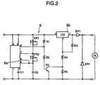
- a control device 6includes a circuit as shown in Fig. 2 .
- the circuitcomprises a pulse generating integral circuit 6a having an astable multivibrator, a pulse-width modulator VR2, a frequency modulator VR1, an amplifier transistor TR and a variable voltage setting integral circuit 6b having a shutdown circuit.
- the voltage setting integral circuit 6bis used for setting a pulse-base voltage VCC2 and a pulse voltage VCC1 of a pulse from the pulse generating integral circuit 6a.
- a diaphragm pump as shown in Fig. 3comprises a housing member 11, a diaphragm 12, a valve body 13 with valves 14, 14' mounted thereon, and a head member having a suction port 15 and discharge port 16.
- the diaphragm 12is fixed to a holder 17 which is connected to a link rod 18.
- the link rod 18has a ring portion in which a crank shaft 19 is rotatably supported.
- a desired discharge per a pumping cycle and desired pumping pressureare regulated by setting a pulse duty ratio and a pulse voltage by means of a modulator VR2 and a voltage setting integral circuit 6b, furthermore, a desired discharge per 1 minute is regulated by setting a frequency by means of a modulator VR1 and a bias voltage, as pulse-base voltage, is set by means of a voltage setting integral circuit 6b.
- the pulse-base voltagehas a such level that the DC motor 5 is not rotated. Then, the control device 6 supplies the pulses to the DC motor 5, the DC motor 5 rotates and torque of the DC motor 5 is transmitted to the crank shaft.
- the disinfectant 3 in the tankis suctioned from the suction port 15 and is discharged into the fluid conduit 1 through the discharge port 16 and the pipe 2.
- the disinfectant 3is mixed to water flowing in the conduit 1 at a predetermined ratio.
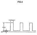
- the detected signal of the flow sensor 7is supplied to the control device 6, the control device modulates pulse (PW1,PW2,VCC1 as shown Fig.4) automatically depending on the detected signal to regulate discharge of the diaphragm pump 4, thereby discharge of the disinfectant 3 is proportioned to flow amount of water in conduit 1.
- a bias voltagecan applied to the DC motor 5, even when the DC motor 5 is not rotated. This makes it possible to prevent an overshoot high voltage from occurring at rising and falling edges of a pulse and to reduce a rushing high current applied to the DC motor 5.
- Fig. 5is a graph showing the relation between discharge and a pumping cycle in accordance to pulse-width in the experimental results of this embodiment.
- the vertical axisrepresents discharge of the diaphragm pump 4 and the horizontal axis represents a pumping cycle, each of four curves is in the case of DC motor 5 supplied of pulse-width at 10ms (milli second),15ms, 18ms and 20ms. It can be understood that discharge of the diaphragm pump 4 is increased at a substantially constant in proportion to pulse-width, in the range of from approximately 2.0 cc/min. to 20.0 cc/min.
- the DC motor used in the experimentis a ordinary DC motor having a commutator, such the DC motor can be used for driving a metering diaphragm pump which continuously regulates discharge, when using the control device 6 of this invention.
- Fig. 6is a graph shown the relation between the temperature and running time of the DC motor 5.
- the curve represented by the symbol Ais in the case of supplying direct current at a constant voltage of 2V to the DC motor
- the curve represented by the symbol Bis in the case of supplying pulses which are modulated a pulse voltage 4V ( VCC 1) and pulse-base voltage 0V (VCC2, non bias voltage )
- the curve represented by the symbol Cis in the case of this embodiment of this invention, supplying pulses of 4V(VCC1) and 1V (VCC2).
- the curve Ashows the temperature of the DC motor rises up to 56°C in short running time at 3600rpm.
- the curve Bshows the temperature of the DC motor rises to 39°C at running time of 280hrs, but pules waveform applied to the DC motor as shown in Fig. 6 B, high voltage overshoot generates at pulse rising and falling points and a spark occurs at a brush contacting surface of a commutator to deposit carbon at the commutator.
- the curve Cshows the temperature characteristics in the case of this invention where a bias voltage is applied to the DC motor at such a level that the DC motor is not rotated, applied pulse waveform is shown in Fig.6 C, a overshoot is restricted
- the controlling device for a diaphragm pump of the present inventionis to provide an arrangement that a discharge of diaphragm pump is accurately regulated in stable manner, through the use of a ordinary DC motor with commutator and a simple controlling circuit which includes a pulse generating means and voltage setting means. Furthermore, according to the control device of the present invention, a overshoot high voltage generating when applying a pulse to a DC motor is restricted by means of a control circuit including a applying means a bias voltage to a DC motor so that a DC motor has a long service life.
Landscapes
- Engineering & Computer Science (AREA)
- Mechanical Engineering (AREA)
- General Engineering & Computer Science (AREA)
- Control Of Direct Current Motors (AREA)
- Reciprocating Pumps (AREA)
Description
- The present invention relates to a control device for a DC motor with a brushcommutator for driving a crankshaft of a diaphragm pump, and particularly forcontrolling discharge of a DC motor driven diaphragm pump which is used as ametering injection pump.
- EP-A-0 363 672 discloses that in a blood pressure monitor a blood pressurecuff is inflated by a pump driven by an electric motor. A control circuit calculatesthe rate of inflation of said cuff over a predetermined period, compares said rateto a desired rate and generates a control signal to adjust the current supply ofsaid motor to control the inflation rate. The motor speed is controlled by theadjustment of the duty cycle of the voltage applied to said motor.
- US-A-4 547 680 discloses a diaphragm pump wherein the diaphragm isdeformable by the reciprocable armature of an electromagnet which isenergizable at a selected frequency by a timer circuit and at random frequencyby a pulse generator. The pulse generator is connectable with theelectromagnet by a cable having separable male and female coupling elementswhich automatically deactivate the timer circuit when the male coupling elementis inserted into the female coupling element. A selector switch is provided todeactivate the timer circuit independently of the coupling elements. A knobserves to adjust a potentiometer of the timer circuit simultaneously with closingof the selector switch so that the frequency at which the timer circuit canenergize the electromagnet is reduced to a minimum value.
- US-A-4,397,610 discloses a reciprocable liquid pump driven by a direct currentelectric motor wherein the motor drive voltage, and thereby pump reciprocation,and output pressure, is selectively controlled by a circuit including an electromechanical transducer coupled in pressure sensing relation to the liquid pumpoutput, a manually operable pressure set point switch, and a silicon-controlledrectifier circuit. The document is directed to improvements in pressureregulation and control for pumping systems, preferably pumping systemsadapted for portable paint spraying equipment, wherein the pressure fluctuationrange may be reduced by at least an order of magnitude from prior art systems.The apparatus includes a direct current (DC) motor mechanically coupled indriving relationship to a reciprocable pump, wherein the pump output pressureis monitored by an electromechanical sensing device which delivers a voltagesignal proportional to pump output pressure. The voltage signal is connected toan electronic circuit which has as another input a manual voltage setting foradjusting a setpoint pressure, the setpoint signal and pressure signal beingcompared and the difference between the two signals generating an error drivesignal which is amplified and compared against a DC voltage reference and atiming signal. The combination of the timing signal and the error drive signal isused to develop a gating signal over a portion of the timing signal period. Thegating signal is fed into a silicon controlled rectifier (SCR) circuit for controllingthe gating time of the silicon controlled rectifier circuit so as to regulate the DCdrive voltage into the motor. When the set point and pressure signals becomeequal the SCR voltage drive into the motor drops to near zero, but motor drivecurrent remains at the level necessary to develop sufficient motor torque to holdthe pump output pressure at the set point value. Under other set point andpressure signal conditions a DC drive signal is coupled into the motor to providea DC drive voltage of sufficient magnitude to reciprocate the pump and therebyincrementally increase the pump output pressure to the set point value.
- A electric motor driven diaphragm pump has been shown in the prior art.A electric motor used as driving device for a diaphragm pump is commonly astepping motor or a DC motor (Direct Current motor). When a stepping motor isused, discharge of the pump is controlled by means of controlling a rotationspeed of the stepping motor by modifying frequency or duty ratio of appliedpulses to the stepping motor. Although discharge of the pump is accuratelyregulated by the stepping motor, as shown in Fig. 7 depending on the duty ratioof pulses, discharge of the pump is so largely changed that is not applicable to adiaphragm pump for small amount metering. Furthermore, a stepping motor anda pulse frequency modulating device or a pulse duty control device are expensiveand the weight of these devices are heavy. In Fig.7, the relationship between arotation speed of a stepping motor and discharge of a diaphragm pump isillustrated in the case of setting a pulse width(PW1) at 40ms, 100ms and 200ms.
- In the case of using a DC motor for driving a diaphragm pump, the DCmotor is applied direct current at a constant voltage to be rotated at constantspeed, thereby the diaphragm pump discharges continuously constant amount offluid. A flow control valve is required to be provided in a line after the dischargeport of the diaphragm pump for metering a amount of fluid. Moreover, when aDC motor runs continuously, the temperature of the motor becomes high as shown onthe curve A in Fig. 6. The curve A illustrates the changing temperature of a DC motorwhen it runs at 3,600 rpm (applied 2V DC).
- Another controlling device for a DC motor as an actuator of a diaphragmpump is to regulate rotating amount of the DC motor by application of pulses.When applying pulses, a DC motor rotates intermittently and pumping pressure of a diaphragm pump is controlled by varying applied pulse voltage, anddischarge per pumping cycle is regulated by modulating the duty ratio of appliedpulses. In Fig. 6, the curve B shows temperature of a DC motor in this case, thetemperature of the motor is not so high but an overshoot at rising and fallingperiod of a pulse (as shown in Fig. 6B) is repeatedly impressed to the DCmotor, generating a spark at the commutator of the motor and deposit carbon in abrush contact surface of a commutator. This results in a reduction of the service lifeof the DC motor.
- In view of the foregoing, it is the main object of this invention toprovide a controlling device for a DC motor for driving a diaphragm pump, in order tosupply and control a predetermined small amount fluid in a stable manner andwhich can prolong the service life of the DC motor while reducing the cost.
- Another object of the present invention is to provide a controlling devicefor a DC motor for driving a diaphragm pump, which applies pulses tothe DC motor but avoids voltageovershoot when applying the pulse. Discharge of a diaphragm pump isregulated by modifying duty ratio or frequency of applied pulses.
- The control device for a DC motor of this invention comprises, thefeatures as set forth in claim 1. Preferred embodiments of the presentinvention may be gathered from the dependent claims.
- The above and further objects and novel features of the presentinvention will more fully appear from the following detailed description whenthe same is read in connection with the accompanying drawings.
- Fig. 1 diagrammatically illustrates an embodiment of a meteringdiaphragm pump controlling system of the present invention.
- Fig. 2 is a schematic diagram of a circuit which may be employed by the device of Fig. 1,
- Fig. 3 is a schematic side elevation view of an example of a diaphragmpump.
- Fig. 4 is a wave form chart of pulse applying to a DC motor.
- Fig. 5 is a graph showing the relations between discharge and appliedpulse duty ratio of a DC motor driving a diaphragm pump in the experimentresults of an embodiment of the invention.
- Fig. 6 is a graph showing the temperature - time relations for a DCmotor of the invention and of prior arts.
- Fig. 7 is a graph showing the relations between discharge and appliedpulse duty of a stepping motor driving a diaphragm pump.
- The preferred embodiment of this invention will now be described indetail with reference to the accompanying drawings.
- The diaphragm pump controlling system shown in Fig. 1 is used fora metering injection pump. The
diaphragm pump 4 driven byDC motor 5discharges liquid 3 from a tank into a fluid conduit 1 through a injectingpipe 2.Theliquid 3, for example disinfectant, is mixed to flowing water in the conduit1 at predetermined constant rate.
Acontrol device 6 supplies pulses toDC motor 5 and modulates a duty ratio orfrequency or voltage of the pulses to regulate discharge of thediaphragm pump 4.A flow sensor orpressure sensor 7 is provided in the conduit 1 for detecting aflow amount in the conduit 1 and detected signals are supplied to thecontroldevice 6. - A
control device 6 includes a circuit as shown in Fig. 2 . The circuitcomprises a pulse generatingintegral circuit 6a having an astable multivibrator, apulse-width modulator VR2, a frequency modulator VR1, an amplifier transistorTR and a variable voltage settingintegral circuit 6b having a shutdown circuit.The voltage settingintegral circuit 6b is used for setting a pulse-base voltageVCC2 and a pulse voltage VCC1 of a pulse from the pulse generatingintegralcircuit 6a. - A diaphragm pump as shown in Fig. 3 comprises a
housing member 11, adiaphragm 12, avalve body 13 withvalves 14, 14' mounted thereon, and a headmember having asuction port 15 anddischarge port 16. Thediaphragm 12 isfixed to aholder 17 which is connected to alink rod 18. Thelink rod 18 has aring portion in which acrank shaft 19 is rotatably supported. - In operation of the diaphragm pump controlling system in Fig 1, a desireddischarge per a pumping cycle and desired pumping pressure are regulated bysetting a pulse duty ratio and a pulse voltage by means of a modulator VR2 anda voltage setting
integral circuit 6b, furthermore, a desired discharge per 1 minuteis regulated by setting a frequency by means of a modulator VR1 and a biasvoltage, as pulse-base voltage, is set by means of a voltage settingintegral circuit 6b. The pulse-base voltage has a such level that theDC motor 5 is not rotated.Then, thecontrol device 6 supplies the pulses to theDC motor 5, theDC motor 5rotates and torque of theDC motor 5 is transmitted to the crank shaft. 19 of thediaphragm pump 4 to reciprocate the link rod and thediaphragm 12. Thedisinfectant 3 in the tank is suctioned from thesuction port 15 and is dischargedinto the fluid conduit 1 through thedischarge port 16 and thepipe 2. Thedisinfectant 3 is mixed to water flowing in the conduit 1 at a predetermined ratio.If desired, the detected signal of theflow sensor 7 is supplied to thecontroldevice 6, the control device modulates pulse (PW1,PW2,VCC1 as shown Fig.4)automatically depending on the detected signal to regulate discharge of thediaphragm pump 4, thereby discharge of thedisinfectant 3 is proportioned toflow amount of water in conduit 1. - By means of the
control device 6 setting a pulse-base voltage,approximately 1.0 V in this embodiment, a bias voltage can applied to theDCmotor 5, even when theDC motor 5 is not rotated. This makes it possible toprevent an overshoot high voltage from occurring at rising and falling edges ofa pulse and to reduce a rushing high current applied to theDC motor 5. - Fig. 5 is a graph showing the relation between discharge and a pumpingcycle in accordance to pulse-width in the experimental results of thisembodiment. In Fig.5, the vertical axis represents discharge of the
diaphragm pump 4 and the horizontal axis represents a pumping cycle, each of four curves isin the case ofDC motor 5 supplied of pulse-width at 10ms (milli second),15ms,18ms and 20ms. It can be understood that discharge of thediaphragm pump 4 isincreased at a substantially constant in proportion to pulse-width, in the range offrom approximately 2.0 cc/min. to 20.0 cc/min. - The DC motor used in the experiment is a ordinary DC motor having acommutator, such the DC motor can be used for driving a metering diaphragmpump which continuously regulates discharge, when using the
control device 6 ofthis invention. - Fig. 6 is a graph shown the relation between the temperature andrunning time of the
DC motor 5. In Fig.6, the curve represented by the symbol Ais in the case of supplying direct current at a constant voltage of 2V to the DCmotor, the curve represented by the symbol B is in the case of supplying pulseswhich are modulated a pulse voltage 4V ( VCC 1) and pulse-base voltage 0V(VCC2, non bias voltage ),the curve represented by the symbol C is in the case ofthis embodiment of this invention, supplying pulses of 4V(VCC1) and 1V(VCC2). - The curve A shows the temperature of the DC motor rises up to 56°Cin short running time at 3600rpm. The curve B shows the temperature of the DCmotor rises to 39°C at running time of 280hrs, but pules waveform applied to theDC motor as shown in Fig. 6 B, high voltage overshoot generates at pulse risingand falling points and a spark occurs at a brush contacting surface of a commutatorto deposit carbon at the commutator. The curve C shows the temperaturecharacteristics in the case of this invention where a bias voltage is applied to theDC motor at such a level that the DC motor is not rotated, applied pulsewaveform is shown in Fig.6 C, a overshoot is restricted
- It is clear from these curves and the waveforms that the temperatureof the DC motor of this invention is controlled to approximately half thetemperature of the A type as known prior art, and a overshoot high voltage isrestricted to approximately 2/3 that of the B type with no bias voltage applied.
- As described above, it is evident that the controlling device for a diaphragm pump of the present invention is to provide an arrangement that adischarge of diaphragm pump is accurately regulated in stable manner, throughthe use of a ordinary DC motor with commutator and a simple controlling circuitwhich includes a pulse generating means and voltage setting means. Furthermore,according to the control device of the present invention, a overshoot high voltagegenerating when applying a pulse to a DC motor is restricted by means of acontrol circuit including a applying means a bias voltage to a DC motor so that aDC motor has a long service life.
- While the invention has been described in detail and with referenceto specific embodiment thereof, it will be apparent to one skilled in the art thatvarious changes and modifications can be made therein without departing fromthe scope of the invention as defined by theappended claims.
Claims (4)
- A control device (6) for a DC motor (5) with a brush commutator for drivinga crankshaft (19) of a diaphragm pump (4), comprising:characterized bya pulse generating circuit means (6a) for generating and supplying anelectrical pulse to said DC motor (5);
a voltage setting circuit means (6b) connected to said pulse generatingcircuit means (6a) for setting a variable voltage (VCC1) of the electricalpulse and applying a pulse-base bias voltage (VCC2) to said DC motor(5) at a level such that said DC motor (5) is not rotated when no electricalpulse is applied. - A control device according to claim 1, wherein said bias voltage (VCC2) isless than 2V.
- A control device according to claim 1 or 2, wherein said pulse generatingcircuit means (6a) comprises a pulse generating integral circuit including anastable multivibrator,
wherein said voltage setting circuit means (6b) includes a voltage settingintegral circuit for setting the bias voltage (VCC2) applied to said DC motor(5) and the pulse voltage (VCC1) of the electrical pulse. - A control device according to claim 3, wherein said control device (6)further comprises an amplifying circuit (TR) connected between said pulsegenerating integral circuit (6a) and said voltage setting integral circuit (6b).
Priority Applications (4)
| Application Number | Priority Date | Filing Date | Title |
|---|---|---|---|
| JP05016098AJP3997318B2 (en) | 1998-02-16 | 1998-02-16 | Pump control method and control apparatus |
| EP99112608AEP1065380B1 (en) | 1998-02-16 | 1999-07-01 | DC-Motor control circuit for a diaphragm pump |
| DE69917241TDE69917241T2 (en) | 1999-07-01 | 1999-07-01 | DC motor control circuit for a diaphragm pump |
| US09/359,133US6154605A (en) | 1998-02-16 | 1999-07-23 | Control device for diaphragm pump |
Applications Claiming Priority (3)
| Application Number | Priority Date | Filing Date | Title |
|---|---|---|---|
| JP05016098AJP3997318B2 (en) | 1998-02-16 | 1998-02-16 | Pump control method and control apparatus |
| EP99112608AEP1065380B1 (en) | 1998-02-16 | 1999-07-01 | DC-Motor control circuit for a diaphragm pump |
| US09/359,133US6154605A (en) | 1998-02-16 | 1999-07-23 | Control device for diaphragm pump |
Publications (2)
| Publication Number | Publication Date |
|---|---|
| EP1065380A1 EP1065380A1 (en) | 2001-01-03 |
| EP1065380B1true EP1065380B1 (en) | 2004-05-12 |
Family
ID=27239980
Family Applications (1)
| Application Number | Title | Priority Date | Filing Date |
|---|---|---|---|
| EP99112608AExpired - LifetimeEP1065380B1 (en) | 1998-02-16 | 1999-07-01 | DC-Motor control circuit for a diaphragm pump |
Country Status (3)
| Country | Link |
|---|---|
| US (1) | US6154605A (en) |
| EP (1) | EP1065380B1 (en) |
| JP (1) | JP3997318B2 (en) |
Families Citing this family (26)
| Publication number | Priority date | Publication date | Assignee | Title |
|---|---|---|---|---|
| DE29821910U1 (en)* | 1998-12-09 | 1999-02-04 | ABEL GmbH & Co. KG, 21514 Büchen | Control device for a diaphragm pump |
| US6759824B2 (en)* | 2001-07-13 | 2004-07-06 | Matsushita Electric Industrial Co., Ltd. | Motor controller and method of driving DC motor |
| DE10224750A1 (en) | 2002-06-04 | 2003-12-24 | Fresenius Medical Care De Gmbh | Device for the treatment of a medical fluid |
| US7631788B2 (en)* | 2003-10-15 | 2009-12-15 | Zavida Coffee Company Inc | Fluid dispensing system suitable for dispensing liquid flavorings |
| US7892304B2 (en)* | 2004-12-17 | 2011-02-22 | Texaco Inc. | Apparatus and method for controlling compressor motor speed in a hydrogen generator |
| US7935074B2 (en) | 2005-02-28 | 2011-05-03 | Fresenius Medical Care Holdings, Inc. | Cassette system for peritoneal dialysis machine |
| US8197231B2 (en) | 2005-07-13 | 2012-06-12 | Purity Solutions Llc | Diaphragm pump and related methods |
| KR100786480B1 (en) | 2006-11-30 | 2007-12-17 | 삼성에스디아이 주식회사 | Module type fuel cell system |
| KR100811982B1 (en) | 2007-01-17 | 2008-03-10 | 삼성에스디아이 주식회사 | Fuel cell system and control method thereof |
| US8192401B2 (en) | 2009-03-20 | 2012-06-05 | Fresenius Medical Care Holdings, Inc. | Medical fluid pump systems and related components and methods |
| WO2011008858A1 (en) | 2009-07-15 | 2011-01-20 | Fresenius Medical Care Holdings, Inc. | Medical fluid cassettes and related systems and methods |
| US8720913B2 (en) | 2009-08-11 | 2014-05-13 | Fresenius Medical Care Holdings, Inc. | Portable peritoneal dialysis carts and related systems |
| WO2011067370A1 (en)* | 2009-12-04 | 2011-06-09 | Emitec Gesellschaft Für Emissionstechnologie Mbh | Delivery device for delivering a reducing agent |
| JP5636615B2 (en)* | 2010-01-05 | 2014-12-10 | 株式会社イワキ | Pump system |
| DE102010053973A1 (en) | 2010-12-09 | 2012-06-14 | Fresenius Medical Care Deutschland Gmbh | Medical device with a heater |
| WO2012087798A2 (en) | 2010-12-20 | 2012-06-28 | Fresenius Medical Care Holdings, Inc. | Medical fluid cassettes and related systems and methods |
| US9624915B2 (en) | 2011-03-09 | 2017-04-18 | Fresenius Medical Care Holdings, Inc. | Medical fluid delivery sets and related systems and methods |
| MX341315B (en) | 2011-04-21 | 2016-08-12 | Fresenius Medical Care Holdings Inc | Medical fluid pumping systems and related devices and methods. |
| US9186449B2 (en) | 2011-11-01 | 2015-11-17 | Fresenius Medical Care Holdings, Inc. | Dialysis machine support assemblies and related systems and methods |
| US9610392B2 (en) | 2012-06-08 | 2017-04-04 | Fresenius Medical Care Holdings, Inc. | Medical fluid cassettes and related systems and methods |
| US9500188B2 (en) | 2012-06-11 | 2016-11-22 | Fresenius Medical Care Holdings, Inc. | Medical fluid cassettes and related systems and methods |
| US9561323B2 (en) | 2013-03-14 | 2017-02-07 | Fresenius Medical Care Holdings, Inc. | Medical fluid cassette leak detection methods and devices |
| US10117985B2 (en) | 2013-08-21 | 2018-11-06 | Fresenius Medical Care Holdings, Inc. | Determining a volume of medical fluid pumped into or out of a medical fluid cassette |
| US20170055760A1 (en)* | 2014-04-08 | 2017-03-02 | Remington Designs, Llc | Beverage brewing systems and methods for using the same |
| GB2527657A (en)* | 2014-05-20 | 2015-12-30 | Ying Lin Cai | Roundel structure for four-compression-chamber diaphragm pump with multiple effects |
| EP3227554B1 (en)* | 2014-12-01 | 2019-09-18 | Ecolab USA Inc. | A diaphragm pump for dosing a fluid and an according method |
Family Cites Families (11)
| Publication number | Priority date | Publication date | Assignee | Title |
|---|---|---|---|---|
| US3808481A (en)* | 1972-04-14 | 1974-04-30 | Electric Fuel Propulsion Corp | Commutating circuit for electrical vehicle |
| US3855520A (en)* | 1972-12-22 | 1974-12-17 | Allis Chalmers | Control having conduction limit means to vary duty cycle of power switch |
| DE2755343C2 (en)* | 1977-12-12 | 1987-02-26 | Papst-Motoren GmbH & Co KG, 7742 St Georgen | Speed control arrangement |
| US4257746A (en)* | 1978-10-02 | 1981-03-24 | E. I. Du Pont De Nemours And Company | Dosimeter having a low air flow rate |
| US4255722A (en)* | 1979-08-23 | 1981-03-10 | Timex Corporation | Voltage controlled multivibrator having variable frequency and duty cycle |
| US4384825A (en)* | 1980-10-31 | 1983-05-24 | The Bendix Corporation | Personal sampling pump |
| US4397610A (en)* | 1981-03-09 | 1983-08-09 | Graco Inc. | Reciprocable pump with variable speed drive |
| DE3204050C1 (en)* | 1982-02-06 | 1983-07-21 | Chemie Und Filter Gmbh, Verfahrenstechnik Kg, 6900 Heidelberg | Electromagnetically operated axial piston pump, especially diaphragm pump |
| US4969466A (en)* | 1988-09-15 | 1990-11-13 | Spacelabs, Inc. | Inflation rate control circuit for blood pressure cuffs |
| US5295790A (en)* | 1992-12-21 | 1994-03-22 | Mine Safety Appliances Company | Flow-controlled sampling pump apparatus |
| US5627458A (en)* | 1995-07-14 | 1997-05-06 | Nevin; Larry J. | Integrated negative D-C bias circuit |
- 1998
- 1998-02-16JPJP05016098Apatent/JP3997318B2/ennot_activeExpired - Fee Related
- 1999
- 1999-07-01EPEP99112608Apatent/EP1065380B1/ennot_activeExpired - Lifetime
- 1999-07-23USUS09/359,133patent/US6154605A/ennot_activeExpired - Fee Related
Also Published As
| Publication number | Publication date |
|---|---|
| JPH11230045A (en) | 1999-08-24 |
| JP3997318B2 (en) | 2007-10-24 |
| EP1065380A1 (en) | 2001-01-03 |
| US6154605A (en) | 2000-11-28 |
Similar Documents
| Publication | Publication Date | Title |
|---|---|---|
| EP1065380B1 (en) | DC-Motor control circuit for a diaphragm pump | |
| EP0518265B1 (en) | Electronic regulator for gasoline engine driven piston paint pumps | |
| US5711483A (en) | Liquid spraying system controller including governor for reduced overshoot | |
| EP0720693B1 (en) | Flow-metered pumping with load compensation system and method | |
| US6174136B1 (en) | Pump control and method of operating same | |
| EP1222395B1 (en) | Method and apparatus for controlling a pump | |
| US4344743A (en) | Piezoelectric driven diaphragm micro-pump | |
| JPH05205751A (en) | Apparatus and method for automatic voltage control of forced electrolyte flow battery | |
| RU2004109161A (en) | SYSTEM FOR STIMULATING TISSUE HEALING (OPTIONS) | |
| EP0928846A2 (en) | Electro-hydraulic brush down force control | |
| WO2003106042A1 (en) | Adjustable flow texture sprayer with peristaltic pump | |
| CA2679946A1 (en) | Optimized method to drive electric spray guns | |
| WO2004094824A3 (en) | Hydrogen peroxide injection system having closed-loop flow control | |
| WO2001079693A2 (en) | Apparatus for adjusting the stroke length of a pump element | |
| DE69209746D1 (en) | Method and device for controlling a pump system and detection element for such a system | |
| US6031352A (en) | Active alternator load circuit | |
| DE69312183D1 (en) | Control method of an electric motor for driving a centrifugal pump | |
| EP0684010B1 (en) | Automatic blood pressure monitor with a dual-speed control circuit for the DC inflation pump motor | |
| US6939110B2 (en) | Control system for I.C. engine driven blower | |
| CA2331748A1 (en) | A device for the supply of a liquid fuel to a burner member | |
| CA1206378A (en) | Fluid flow machine with an electromagnetically operated diaphragm pump | |
| US4454456A (en) | Method and circuit for operating a spray gun having a vibrating armature drive | |
| US7128539B2 (en) | Method for improved cleaning of a pumping system | |
| SE524605C2 (en) | Air-driven low frequency sound generator and method of controlling the resting position of a piston included in such | |
| CN212155072U (en) | Micro pump with stable and adjustable flow |
Legal Events
| Date | Code | Title | Description |
|---|---|---|---|
| PUAI | Public reference made under article 153(3) epc to a published international application that has entered the european phase | Free format text:ORIGINAL CODE: 0009012 | |
| AK | Designated contracting states | Kind code of ref document:A1 Designated state(s):CH DE FR GB LI | |
| AX | Request for extension of the european patent | Free format text:AL;LT;LV;MK;RO;SI | |
| 17P | Request for examination filed | Effective date:20010620 | |
| AKX | Designation fees paid | Free format text:CH DE FR GB LI | |
| 17Q | First examination report despatched | Effective date:20021030 | |
| GRAP | Despatch of communication of intention to grant a patent | Free format text:ORIGINAL CODE: EPIDOSNIGR1 | |
| GRAA | (expected) grant | Free format text:ORIGINAL CODE: 0009210 | |
| GRAS | Grant fee paid | Free format text:ORIGINAL CODE: EPIDOSNIGR3 | |
| AK | Designated contracting states | Kind code of ref document:B1 Designated state(s):CH DE FR GB LI | |
| REG | Reference to a national code | Ref country code:GB Ref legal event code:FG4D | |
| REG | Reference to a national code | Ref country code:CH Ref legal event code:EP | |
| REF | Corresponds to: | Ref document number:69917241 Country of ref document:DE Date of ref document:20040617 Kind code of ref document:P | |
| REG | Reference to a national code | Ref country code:CH Ref legal event code:NV Representative=s name:RIEDERER HASLER & PARTNER PATENTANWAELTE AG | |
| ET | Fr: translation filed | ||
| PLBE | No opposition filed within time limit | Free format text:ORIGINAL CODE: 0009261 | |
| STAA | Information on the status of an ep patent application or granted ep patent | Free format text:STATUS: NO OPPOSITION FILED WITHIN TIME LIMIT | |
| 26N | No opposition filed | Effective date:20050215 | |
| PGFP | Annual fee paid to national office [announced via postgrant information from national office to epo] | Ref country code:DE Payment date:20091028 Year of fee payment:11 Ref country code:CH Payment date:20091014 Year of fee payment:11 | |
| PGFP | Annual fee paid to national office [announced via postgrant information from national office to epo] | Ref country code:GB Payment date:20091014 Year of fee payment:11 Ref country code:FR Payment date:20091029 Year of fee payment:11 | |
| REG | Reference to a national code | Ref country code:CH Ref legal event code:PL | |
| GBPC | Gb: european patent ceased through non-payment of renewal fee | Effective date:20100701 | |
| REG | Reference to a national code | Ref country code:FR Ref legal event code:ST Effective date:20110331 | |
| PG25 | Lapsed in a contracting state [announced via postgrant information from national office to epo] | Ref country code:DE Free format text:LAPSE BECAUSE OF NON-PAYMENT OF DUE FEES Effective date:20110201 Ref country code:CH Free format text:LAPSE BECAUSE OF NON-PAYMENT OF DUE FEES Effective date:20100731 Ref country code:LI Free format text:LAPSE BECAUSE OF NON-PAYMENT OF DUE FEES Effective date:20100731 | |
| REG | Reference to a national code | Ref country code:DE Ref legal event code:R119 Ref document number:69917241 Country of ref document:DE Effective date:20110201 | |
| PG25 | Lapsed in a contracting state [announced via postgrant information from national office to epo] | Ref country code:FR Free format text:LAPSE BECAUSE OF NON-PAYMENT OF DUE FEES Effective date:20100802 | |
| PG25 | Lapsed in a contracting state [announced via postgrant information from national office to epo] | Ref country code:GB Free format text:LAPSE BECAUSE OF NON-PAYMENT OF DUE FEES Effective date:20100701 |