EP1063125A1 - Actuator for a motor vehicle - Google Patents
Actuator for a motor vehicleDownload PDFInfo
- Publication number
- EP1063125A1 EP1063125A1EP00108886AEP00108886AEP1063125A1EP 1063125 A1EP1063125 A1EP 1063125A1EP 00108886 AEP00108886 AEP 00108886AEP 00108886 AEP00108886 AEP 00108886AEP 1063125 A1EP1063125 A1EP 1063125A1
- Authority
- EP
- European Patent Office
- Prior art keywords
- actuator according
- friction
- friction adjusting
- actuator
- elements
- Prior art date
- Legal status (The legal status is an assumption and is not a legal conclusion. Google has not performed a legal analysis and makes no representation as to the accuracy of the status listed.)
- Granted
Links
- 229910052751metalInorganic materials0.000claimsabstractdescription8
- 239000002184metalSubstances0.000claimsabstractdescription8
- 239000002131composite materialSubstances0.000claimsabstractdescription3
- 229910052782aluminiumInorganic materials0.000claimsdescription4
- XAGFODPZIPBFFR-UHFFFAOYSA-NaluminiumChemical compound[Al]XAGFODPZIPBFFR-UHFFFAOYSA-N0.000claimsdescription4
- FYYHWMGAXLPEAU-UHFFFAOYSA-NMagnesiumChemical compound[Mg]FYYHWMGAXLPEAU-UHFFFAOYSA-N0.000claimsdescription2
- 238000005452bendingMethods0.000claimsdescription2
- 238000010276constructionMethods0.000claimsdescription2
- 229910052749magnesiumInorganic materials0.000claimsdescription2
- 239000011777magnesiumSubstances0.000claimsdescription2
- 230000000694effectsEffects0.000description3
- 238000013016dampingMethods0.000description2
- 238000004519manufacturing processMethods0.000description2
- 238000004080punchingMethods0.000description2
- AZDRQVAHHNSJOQ-UHFFFAOYSA-NalumaneChemical group[AlH3]AZDRQVAHHNSJOQ-UHFFFAOYSA-N0.000description1
- 230000009286beneficial effectEffects0.000description1
- 230000005540biological transmissionEffects0.000description1
- 230000008878couplingEffects0.000description1
- 238000010168coupling processMethods0.000description1
- 238000005859coupling reactionMethods0.000description1
- 239000011521glassSubstances0.000description1
- 239000000463materialSubstances0.000description1
Images


Classifications
- B—PERFORMING OPERATIONS; TRANSPORTING
- B60—VEHICLES IN GENERAL
- B60R—VEHICLES, VEHICLE FITTINGS, OR VEHICLE PARTS, NOT OTHERWISE PROVIDED FOR
- B60R1/00—Optical viewing arrangements; Real-time viewing arrangements for drivers or passengers using optical image capturing systems, e.g. cameras or video systems specially adapted for use in or on vehicles
- B60R1/02—Rear-view mirror arrangements
- B60R1/06—Rear-view mirror arrangements mounted on vehicle exterior
- B60R1/062—Rear-view mirror arrangements mounted on vehicle exterior with remote control for adjusting position
- B60R1/07—Rear-view mirror arrangements mounted on vehicle exterior with remote control for adjusting position by electrically powered actuators
- B60R1/072—Rear-view mirror arrangements mounted on vehicle exterior with remote control for adjusting position by electrically powered actuators for adjusting the mirror relative to its housing
- Y—GENERAL TAGGING OF NEW TECHNOLOGICAL DEVELOPMENTS; GENERAL TAGGING OF CROSS-SECTIONAL TECHNOLOGIES SPANNING OVER SEVERAL SECTIONS OF THE IPC; TECHNICAL SUBJECTS COVERED BY FORMER USPC CROSS-REFERENCE ART COLLECTIONS [XRACs] AND DIGESTS
- Y10—TECHNICAL SUBJECTS COVERED BY FORMER USPC
- Y10T—TECHNICAL SUBJECTS COVERED BY FORMER US CLASSIFICATION
- Y10T74/00—Machine element or mechanism
- Y10T74/18—Mechanical movements
- Y10T74/18568—Reciprocating or oscillating to or from alternating rotary
- Y10T74/188—Reciprocating or oscillating to or from alternating rotary including spur gear
- Y10T74/18808—Reciprocating or oscillating to or from alternating rotary including spur gear with rack
- Y10T74/18816—Curvilinear rack
- Y10T74/18824—Curvilinear rack with biasing means
- Y—GENERAL TAGGING OF NEW TECHNOLOGICAL DEVELOPMENTS; GENERAL TAGGING OF CROSS-SECTIONAL TECHNOLOGIES SPANNING OVER SEVERAL SECTIONS OF THE IPC; TECHNICAL SUBJECTS COVERED BY FORMER USPC CROSS-REFERENCE ART COLLECTIONS [XRACs] AND DIGESTS
- Y10—TECHNICAL SUBJECTS COVERED BY FORMER USPC
- Y10T—TECHNICAL SUBJECTS COVERED BY FORMER US CLASSIFICATION
- Y10T74/00—Machine element or mechanism
- Y10T74/20—Control lever and linkage systems
- Y10T74/20396—Hand operated
- Y10T74/20402—Flexible transmitter [e.g., Bowden cable]
- Y10T74/2042—Flexible transmitter [e.g., Bowden cable] and hand operator
- Y10T74/20432—Flexible transmitter [e.g., Bowden cable] and hand operator for moving a mirror
Definitions
- the inventionrelates to an actuator for a motor vehicle, wherein a first element the vehicle can be fixed and one with the first element by at least one Pivot axis pivotally connected second element, a holder for an actuator has, the second element with at least one of a drive between the first and the second element actuable, adjusting element and at least one on which first element adjacent, friction element is connected.
- the known mirrorhas the disadvantage that the adjustment elements within the Drive housing are housed and thus a relative of the pivot axes have a short distance. Therefore, the adjustment torque that is from the drive to the Actuator is exercised relatively little.
- Another disadvantageis the undefined Frictional forces generated by the spherical shell segments. Because this one Plastic material, their elasticity may deteriorate over time.
- At least one friction element an adjustment elementform a one-piece friction adjustment element, which as Connection means between the first and the second element is used and the friction adjusting element is loaded on train.
- the friction adjusting elementpreferably consists of a metal band or a Composite part with at least one toothed area, because this training is special easy to manufacture, and has sufficient strength.
- the gearingcan be stamped into the metal band, by punching, deep drawing or punching and Bending be made.
- the friction adjustment elementcan also be used as a technical plastic part be trained, especially if there are special requirements for the quality of the Gearing.
- At least one friction adjustment elementis connected to the connection points second element connected.
- a second solution to the problemis achieved in that a multi-link chain Adjustment element and the friction element forms, wherein the chain is subjected to tension
- the chainhas the advantage of being able to move in all directions, thereby preventing movement can follow an actuator in all directions.
- the driveengages in or between the chain links by a gear To produce a coupling, this means that there is no need for separate gears required.
- each friction adjusting elementcan be driven independently of one another, each friction adjusting element at least two of the connection points is connected to the second element, at Use of two connection points per friction adjusting element, one each Connection point of the second element with the first friction adjusting element on a Junction of the second element with the second friction adjusting element follows, wherein the joints at a uniform angular distance of 90 ° with respect to one Intersection of the two pivot axes are arranged, each friction adjusting element includes the first element and the friction adjusting elements at least partially in or on the first Element are guided.
- the Toothingscan be carried out simply because no or only little non-axial Movements occur.
- the second elementcan be comprised of the first element, whereby the second element is held securely on the first element.
- secure guidesare provided in or on the first element.
- the two friction adjustment elementsintersect at one point, this is necessary Form the first element so that the two friction adjusting elements are not mutually hinder. The same effect could be achieved if the friction adjustment elements were designed accordingly to reach. Especially when using thin metal strips there is no obstruction between the two friction adjustment elements, even if these slide on each other. This makes the first element particularly easy to design. The the two friction adjustment elements can then be at essentially the same distance run to the intersection of the swivel axes.
- the tensile forcescan be achieved, for example be formed that at least one friction adjusting element with a resilient area is, wherein it is particularly preferred to design the resilient area in wave form, because this allows the desired maximum travel to be set very precisely. in the assembled state, the resilient areas are fully stretched to run idle during operation to rule out as far as possible.
- the second elementis in the designed to be essentially rigid, as a result of which vibrations of the actuator become decisive suppressed.
- the second elementhas an annular edge provided annular wall, which has a particularly stiffening effect on the second element. At this edge / this wall are the connection points to the molded on at least one friction adjusting element. As a result, the adjustment forces on cheapest to transfer to the entire second element.
- the friction adjustment elementsare designed without a resilient area.
- the spring meansare easy by introducing a slot-shaped recess in the second element trainable.
- At least one friction adjustment elementis articulated to the second element, As a result, it is not necessary to close the friction adjustment elements with curved teeth Mistake.
- thiscan be from a Aluminum deep-drawn part, an aluminum die-cast part or a magnesium die-cast part be trained.
- a particularly low-component constructionis achieved in that between the first and no separate fastening means are provided for the second element. This is possible because the friction adjustment elements are sufficient as fastening elements.
- Anti-rotation between the first and the second elementis one with guides and grooved calotte provided. Due to the anti-rotation device is a safe and exact positioning possible.
- Recessesare expediently provided in the first element through which Gear means of the drive with the one-piece friction adjustment elements in engagement can come.
- the angle of the friction adjustment elementsslightly deviate from each other in the extreme positions of the second element by 90 °. Therefore, it may be necessary for at least one friction adjusting element in the case of a rigid design at least at one connection point with the second element Has alternatives.
- At least one of the friction adjustment elements in the guideshas no or only one very little play longitudinally moveable, thereby preventing rotation between reached the first element and the second element.
- An additional anti-twist devicethis makes it superfluous.
- To the mobility of the second element compared to the not to restrict the first elementis at least one friction adjustment element with a clear Play in the guides longitudinally movable and slightly laterally movable. It offers itself to form the guides at least partially groove-like.
- the toothed area of at least one friction adjustment elementcan be the first element be facing or be arranged at about 90 ° to it. This makes them different Gear types can be used. It is also possible to have at least the part of a friction adjusting element, that carries the toothed area into the interior of the first element let it protrude.
- At least one friction adjusting element at least in the engagement area with the Gear meansare supported by a support means.
- the gear meanscan high load may Snap over the toothed area of the friction adjustment element. This eliminates the need for an additional overload clutch.
- the support of a friction adjusting elementcan be achieved by using a Support element at least partially engages behind.
- the support elementcan also be used as Snap connection must be executed. This facilitates the assembly of the friction adjustment element, especially if the snap connection in the form of snap hooks is trained.
- the guides and / or the snap connectionare / is in one piece with the first element.
- the support meansare preferably in one piece with the first element or in one piece with the second element.
- Another way to simplify assemblyis to over the support means to connect a film hinge to the first element, the supporting means in its Final assembly position is held via a snap connection.
- a spring elementcan be arranged in the first element and the second element.
- This Spring elementis in the simplest case with the first element or the second Element in one piece, but an additional spring element can also be provided.
- the spring elementtries to move the second element away from the first element move and at least one friction adjusting element holds the second element against the Spring action of the spring element on the first element.
- the second elementcan be mounted against the Spring action of the spring can be pressed against the first element. This allows the ends of the friction adjusting element more easily with the projecting drivers on second element.
- the wall of the first element with recessesthrough which at least one position-determining device can be coupled to the friction adjusting elements.
- a part of the position determination devicecan be arranged within the first element and a second part can be firmly connected to a friction adjusting element, a connection between the two parts being established by the wall of the first element.
- a further possibility of installing a memory deviceis to subsequently place the position determining device on the first element from the outside and to connect it mechanically and electrically to it. This provides a type of modular structure that allows less expensive storage of different types of drives or drive parts.
- the actuator according to the inventionis particularly suitable for actuating a motor vehicle rear view mirror.
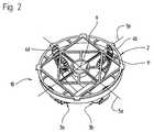
- the first element 1shows an actuator 10, with a first element 1, a second element 2, that of two friction adjustment elements 3a, 3b by two mutually perpendicular Pivot axes 5a, 5b is pivotable, the first element 1 on the second Element 2 is mounted in a pivot bearing 24.
- the first element 1is preferred formed in two parts as a housing.
- Fig. 2shows the friction adjusting elements 3a, 3b Junctions 4a, 4b, 4c, 4d are connected to the second element 2, wherein each a connection point 4a, 4b of the friction adjusting element 3a with the second element a connection point, 4c, 4d of the friction adjusting element 3b with the second element follows and the distances between the connection points 4a, 4b, 4c, 4d around an intersection 6 of FIG Pivot axes 5a, 5b are evenly distributed.
- gear meansin the form of Gears shown as part of a drive for actuating the friction adjusting elements 3a, 3b in toothed areas 11 of the friction adjusting elements 3a, 3b intervention.
- Fig. 3shows an embodiment for the friction adjusting element 3a, 3b, with the toothed area 11, which is designed as an impressed toothing 26, Connection openings 28 which are shaped in the shape of a circular segment and a resilient Area 23 that is wavy.
- 4 and 5show variants of the toothed region 11 of the friction adjusting elements 3a, 3b, the teeth being designed as perforations 27.
- 4is the Perforation 27 round, in Fig. 5 rectangular.
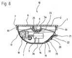
- Fig. 6shows the second element 2, which is designed as a deep-drawn aluminum part with an / an annular edge / wall 14, the pivot bearing 24, brackets 7 for a Actuator, such as a mirror (usually with a mirror glass support), connecting points 4a, 4b, 4c, 4d and struts 29 for connecting the / the annular edge / wall 14 with the pivot bearing 24.
- a Actuatorsuch as a mirror (usually with a mirror glass support)
- connecting points 4a, 4b, 4c, 4d and struts 29for connecting the / the annular edge / wall 14 with the pivot bearing 24.
- connection points 4a, 4b, 4c, 4dare in the form of from Inner surface of the annular edge (s) 14 projecting driver 15a, 15b, 15c, 15d are formed, which are shaped in the shape of an annular segment, so that the respective Pivots of the connection points 4a, 4b, 4c, 4d on the corresponding Pivot axes 5a, 5b lie.
- the pivot bearing 24has a groove 30 provided, which is part of an anti-rotation device.
- Fig. 8shows a simplified sectional view of the actuator 10, with the two-part first element 1, second element 2, intersection 6 of pivot axes 5a, 5b, the drive 9 with the gear means 18, which has a recess 17 in a wall 16 of the first element 1 engages in the toothed area of the friction adjusting element 3a, wherein the friction adjusting element 3a around the first element 1, which is at least partially is spherical and / or cylindrical in shape, is laid around and over the Connection points 4a, 4b is connected to the second element.
- Fig. 8shows a simplified sectional view of the actuator 10, with the two-part first element 1, second element 2, intersection 6 of pivot axes 5a, 5b, the drive 9 with the gear means 18, which has a recess 17 in a wall 16 of the first element 1 engages in the toothed area of the friction adjusting element 3a, wherein the friction adjusting element 3a around the first element 1, which is at least partially is spherical and / or cylindrical in shape, is laid
- the Electrical connections to a connection 21can be made via baffles 22 for example, are injected into the first element 1.
- Fig. 9shows a second embodiment of the invention in which one of a plurality of Chain links 13 existing chain 12, e.g. a ball chain as a friction adjusting element 3a, 3b is used, the chain links forming a toothing due to their shape in which the gear means 18 engages directly.
- a plurality of Chain links 13 existing chain 12e.g. a ball chain as a friction adjusting element 3a, 3b is used, the chain links forming a toothing due to their shape in which the gear means 18 engages directly.
- Fig. 10shows a variant of the second element 2, in its annular / annular Edge / wall 14 recesses 34 are formed, whereby spring means 35 arise, which are provided with the connecting means 4a, 4b, 4c, 4d. In this way, the resilient areas of the friction adjusting elements are dispensed with.
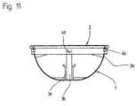
- Fig. 11shows an external view of the actuator, with the first element 1, the groove-like Has guides 38 in which the friction adjusting elements 3a, 3b extend, the ends of which are connected to the second element 2 via the connection points 4b, 4d.
- FIG. 12shows a first embodiment of a support for the friction adjusting element 3a in the form of snap connections 39.
- the snap connectionsare in Engagement area of the transmission means 18 in the toothed area of the friction adjusting element 13 shows a second embodiment of the support 38a shown, which is designed as a web, the two guides 36 together connects.
- 14shows a third embodiment of the support 38a, in which a web with one of the guides 36 over a film hinge 40 and with the second guide 36 is connected via a snap connection.
- a fourth embodiment of the 15shows the support 38b with the second element 2 in one piece.
Landscapes
- Engineering & Computer Science (AREA)
- Multimedia (AREA)
- Mechanical Engineering (AREA)
- Pivots And Pivotal Connections (AREA)
- Mechanical Operated Clutches (AREA)
- Transmission Devices (AREA)
Abstract
Description
Translated fromGermanDie Erfindung betrifft einen Stellantrieb für ein Kraftfahrzeug, wobei ein erstes Element andem Fahrzeug festlegbar ist und ein mit dem ersten Element um zumindest eineSchwenkachse schwenkbar verbundenes zweites Element eine Halterung für ein Stellgliedaufweist, das zweite Element mit zumindest einem, von einem Antrieb zwischen dem erstenund dem zweiten Element betätigbaren, Verstellelelment und zumindest einem, an demersten Element anliegenden, Reibelement verbunden ist.The invention relates to an actuator for a motor vehicle, wherein a first elementthe vehicle can be fixed and one with the first element by at least onePivot axis pivotally connected second element, a holder for an actuatorhas, the second element with at least one of a drive between the firstand the second element actuable, adjusting element and at least one on whichfirst element adjacent, friction element is connected.
Aus der DE-PS 30 26 561 ist bereits ein Stellantrieb bekannt, für dessen Verstellung umzwei zueinander senkrechte Achsen, Verstellelemente in Form von Zahnstangenvorgesehen sind, die von einem Antrieb betätigt werden und für dessen verbesserterVibrationsdämpfung Reibelemente in Form von Kugelschalensegmenten vorhanden sind.From DE-PS 30 26 561 an actuator is already known for its adjustmenttwo mutually perpendicular axes, adjusting elements in the form of racksare provided, which are operated by a drive and for its improvedVibration damping Friction elements in the form of spherical shell segments are available.
Der bekannte Spiegel weist den Nachteil auf, daß die Verstellelemente innerhalb desAntriebsgehäuses untergebracht sind und somit von den Schwenkachsen einen relativgeringen Abstand besitzen. Daher ist auch das Verstellmoment, das vom Antrieb auf dasStellglied ausgeübt wird relativ gering. Ein weiterer Nachteil besteht in den undefiniertenReibkräften, die von den Kugelschalensegmenten erzeugt werden. Da diese ausKunststoffmaterial bestehen, kann ihre elastische Wirkung im Laufe der Zeit nachlassen.The known mirror has the disadvantage that the adjustment elements within theDrive housing are housed and thus a relative of the pivot axeshave a short distance. Therefore, the adjustment torque that is from the drive to theActuator is exercised relatively little. Another disadvantage is the undefinedFrictional forces generated by the spherical shell segments. Because this onePlastic material, their elasticity may deteriorate over time.
Daher ist es Aufgabe der vorliegenden Erfindung bei einem gattungsgemäßenRückblickspiegel für ein besonders hohes Verstellmoment und eine über die Lebensdauermöglichst konstante Reibkraft zu sorgen, wobei die Teileanzahl so gering wie möglich unddie Montierbarkeit besonders einfach ist.It is therefore an object of the present invention in a genericRearview mirror for a particularly high adjustment torque and one over the service lifeto ensure as constant a frictional force as possible, the number of parts being as small as possible andassembly is particularly easy.
Diese Aufgabe wird erfindungsgemäß dadurch gelöst, daß zumindest ein Reibelement miteinem Verstellelement ein einstückiges Reib-Verstellelement bilden, das alsVerbindungsmittel zwischen dem ersten und dem zweiten Element dient und das Reib-Verstellelementauf Zug belastet ist.This object is achieved in that at least one friction elementan adjustment element form a one-piece friction adjustment element, which asConnection means between the first and the second element is used and the friction adjusting elementis loaded on train.
Durch die Anordnung der Reib-Verstellelemente an der Außenseite des ersten Elements istein besonders hohes Verstellmoment möglich und durch den großen Reibradius die Vibrationsdämpfung besonders günstig und die Haltekraft besonders hoch. Durch die Zug-Belastungwerden diese günstigen Wirkungen weiter verstärkt, weil dadurch Spielfreiheithergestellt wird.Due to the arrangement of the friction adjusting elements on the outside of the first elementa particularly high adjustment torque is possible and due to the large friction radiusVibration damping is particularly cheap and the holding force is particularly high. Due to the train loadthese beneficial effects are further strengthened because of the freedom from playwill be produced.
Das Reib-Verstellelement besteht vorzugsweise aus einem Metallband oder einemVerbundteil mit mindestens einem verzahnten Bereich, da diese Ausbildung eine besonderseinfache Herstellbarkeit erlaubt, und eine ausreichende Festigkeit besitzt. Die Verzahnungkann in das Metallband eingeprägt sein, durch Lochen, Tiefziehen oder Stanzen undBiegen hergestellt sein. Das Reib-Verstellelement kann auch als technisches Kunststoffteilausgebildet sein, insbesondere wenn besondere Anforderungen an die Qualität derVerzahnung gestellt werden.The friction adjusting element preferably consists of a metal band or aComposite part with at least one toothed area, because this training is specialeasy to manufacture, and has sufficient strength. The gearingcan be stamped into the metal band, by punching, deep drawing or punching andBending be made. The friction adjustment element can also be used as a technical plastic partbe trained, especially if there are special requirements for the quality of theGearing.
Vorzugsweise ist zumindest ein Reib-Verstellelement über Verbindungsstellen mit demzweiten Element verbunden.Preferably, at least one friction adjustment element is connected to the connection pointssecond element connected.
Eine zweite Lösung der Aufgabe wird dadurch erreicht, daß eine mehrgliedrige Kette dasVerstellelement und das Reibelement bildet, wobei die Kette auf Zug belastet ist Die Ketteweist den Vorteil auf in alle Richtungen beweglich zu sein, wodurch sie den Bewegungeneines Stellglieds in allen Richtungen folgen kann.A second solution to the problem is achieved in that a multi-link chainAdjustment element and the friction element forms, wherein the chain is subjected to tension The chainhas the advantage of being able to move in all directions, thereby preventing movementcan follow an actuator in all directions.
Vorzugsweise greift der Antrieb in oder zwischen die Kettenglieder ein um eine getrieblicheKupplung herzustellen, dadurch sind gesondert einzubringende Verzahnungen nichterforderlich.Preferably, the drive engages in or between the chain links by a gearTo produce a coupling, this means that there is no need for separate gearsrequired.
Um die Verschwenkung des zweiten Elements um zwei zueinander senkrechte Achsen zuermöglichen, sind zwei Reib-Verstellelemente oder zwei Ketten vorgesehen.To pivot the second element about two mutually perpendicular axesallow, two friction adjustment elements or two chains are provided.
Eine bevorzugte Weiterbildung derErfindung wird dadurch erreicht, daß die beiden Reib-Verstellelementeunabhängig voneinander antreibbar sind, jedes Reib-Verstellelement anzumindest zwei der Verbindungsstellen mit dem zweiten Element verbunden ist, beiVerwendung zweier Verbindungsstellen je Reib-Verstellelement, jeweils eineVerbindungsstelle des zweiten Elements mit dem ersten Reib-Verstellelement auf eineVerbindungsstelle des zweiten Elements mit dem zweiten Reib-Verstellelement folgt, wobeidie Verbindungsstellen in einem gleichmäßigen Winkelabstand von 90° in bezug auf einenSchnittpunkt der beiden Schwenkachsen angeordnet sind, jedes Reib-Verstellelement daserste Element umfaßt und die Reib-Verstellelemente zumindest teilweise im oder am erstenElement geführt sind.A preferred further development of the invention is achieved in that the two friction adjusting elementscan be driven independently of one another, each friction adjusting elementat least two of the connection points is connected to the second element, atUse of two connection points per friction adjusting element, one eachConnection point of the second element with the first friction adjusting element on aJunction of the second element with the second friction adjusting element follows, whereinthe joints at a uniform angular distance of 90 ° with respect to oneIntersection of the two pivot axes are arranged, each friction adjusting elementincludes the first element and the friction adjusting elements at least partially in or on the firstElement are guided.
Durch die unabhängig voneinander antreibbaren Reib-Verstellelemente können dieVerzahnungen einfach ausgeführt sein, weil keine oder nur geringe nichtaxialeBewegungen auftreten. Durch die beiden Verbindungsstellen der Reib-Verstellelemente mitdem zweiten Element kann das erste Element umfaßt werden, wodurch das zweite Elementsicher am ersten Element gehalten ist. Um die Reib-Verstellelemente in ihrer Lage zusichern sind Führungen im oder am ersten Element vorgesehen.Due to the independently adjustable friction adjustment elements, theToothings can be carried out simply because no or only little non-axialMovements occur. Through the two connection points of the friction adjustment elementsThe second element can be comprised of the first element, whereby the second elementis held securely on the first element. To position the friction adjustment elementssecure guides are provided in or on the first element.
Da die beiden Reib-Verstellelemente sich an einer Stelle kreuzen, ist es erforderlich daserste Element so zu formen, daß sich die beiden Reib-Verstellelemente nicht gegenseitigbehindern. Den gleichen Effekt könnte man bei entsprechender Ausbildung der Reib-Verstellelementeerreichen. Insbesondere bei Verwendung von dünnen Metallbändernfindet keine Behinderung zwischen den beiden Reib-Verstellelementen statt, auch wenndiese aufeinander gleiten. Dadurch ist das erste Element besonders einfach gestaltbar. Diebeiden Reib-Verstellelemente können dann sogar im wesentlichen im gleichen Abstandzum Schnittpunkt der Schwenkachsen verlaufen.Since the two friction adjustment elements intersect at one point, this is necessaryForm the first element so that the two friction adjusting elements are not mutuallyhinder. The same effect could be achieved if the friction adjustment elements were designed accordinglyto reach. Especially when using thin metal stripsthere is no obstruction between the two friction adjustment elements, even ifthese slide on each other. This makes the first element particularly easy to design. Thethe two friction adjustment elements can then be at essentially the same distancerun to the intersection of the swivel axes.
Bei Verwendung von großvolumigen Reib-Verstellelementen kann es notwendig werden diebeiden Reib-Verstellelemente auf unterschiedlichen Bahnen und zumindest teilweise mitunterschiedlichem Abstand zum Schnittpunkt der Schwenkachsen anzuordnen, damit keinegegenseitige Behinderung stattfinden kann.When using large-volume friction adjustment elements it may be necessarytwo friction adjustment elements on different tracks and at least partially witharrange different distance from the intersection of the swivel axes, so nonemutual disability can take place.
Es ist besonders vorteilhaft sowohl im Stillstand, als auch im Betrieb Zugkräfte auf die Reib-Verstellelementewirken zu lassen, wodurch jedes Spiel zwischen dem ersten und demzweiten Element ausgeschlossen ist. Die Zugkräfte können beispielsweise dadurch erreichtwerden, daß zumindest ein Reib-Verstellelement mit einem federnden Bereich ausgebildetist, wobei besonders bevorzugt wird den federnden Bereich in Wellenform auszuführen, dahierdurch sehr genau der gewünschte maximale Federweg eingestellt werden kann. Immontierten Zustand sind die federnden Bereiche voll gestreckt, um einen Totlauf im Betriebmöglichst auszuschließen.It is particularly advantageous both at a standstill and during operation, pulling forces on the friction adjusting elementslet it take effect, making every game between the first and thesecond element is excluded. The tensile forces can be achieved, for examplebe formed that at least one friction adjusting element with a resilient areais, wherein it is particularly preferred to design the resilient area in wave form, becausethis allows the desired maximum travel to be set very precisely. in theassembled state, the resilient areas are fully stretched to run idle during operationto rule out as far as possible.
Nach einem weiteren wesentlichen Merkmal der Erfindung ist das zweite Element imwesentlichen steif ausgebildet, hierdurch werden Vibrationen des Stellglieds entscheidendunterdrückt.According to a further essential feature of the invention, the second element is in thedesigned to be essentially rigid, as a result of which vibrations of the actuator become decisivesuppressed.
In Weiterbildung der Erfindung ist das zweite Element mit einem ringförmigen Rand/einerringförmigen Wandung versehen, der/die eine besonders versteifende Wirkung auf das zweite Element hat. An diesem Rand/dieser Wandung sind die Verbindungsstellen zu demzumindest einen Reib-Verstellelement angeformt. Dadurch werden die Verstellkräfte amgünstigsten auf das gesamte zweite Element übertragen.In a further development of the invention, the second element has an annular edgeprovided annular wall, which has a particularly stiffening effect on thesecond element. At this edge / this wall are the connection points to themolded on at least one friction adjusting element. As a result, the adjustment forces oncheapest to transfer to the entire second element.
Nach einer besonders einfach zu montierenden Weiterbildung der Erfindung werden dieVerbindungsstellen in Form von aus der Ringinnenfläche vorspringenden Mitnehmerngebildet. Weiter sind diese Mitnehmer Kreisring-Segmentförmig ausgebildet, dadurchkönnen die Mittelpunkte der Kreisringsegmente auf den Schwenkachsen liegen unddennoch Schwenkbewegungen der Reib-Verstellelemente zugelassen und große Momenteübertragen werden.After a particularly easy to install further development of the inventionConnection points in the form of drivers protruding from the inner ring surfaceeducated. Furthermore, these drivers are circular segment shaped, therebythe centers of the circular ring segments can lie on the swivel axes andnevertheless, swiveling movements of the friction adjustment elements are permitted and large momentsbe transmitted.
Durch am zweiten Element vorgesehene Federmittel, an denen die Verbindungsstellenzwischen den Reib-Verstellelementen und dem zweiten Element angeformt sind, könnendie Reib-Verstellelemente ohne federnden Bereich ausgebildet werden. Die Federmittelsind einfach durch Einbringen einer schlitzförmiten Freisparung im zweiten Elementausbildbar.By spring means provided on the second element, at which the connection pointscan be molded between the friction adjusting elements and the second elementthe friction adjustment elements are designed without a resilient area. The spring meansare easy by introducing a slot-shaped recess in the second elementtrainable.
Zumindest ein Reib-Verstellelement ist gelenkig mit dem zweiten Element verbunden,dadurch ist es nicht nötig die Reib-Verstellelemente mit einer gewölbten Verzahnung zuversehen.At least one friction adjustment element is articulated to the second element,As a result, it is not necessary to close the friction adjustment elements with curved teethMistake.
Um Gewicht zu sparen, eine einfache Herstellbarkeit zu erlauben und dennoch eineausreichende Festigkeit des zweiten Elements zu erreichen, kann dieses aus einemAluminium-Tiefziehteil, einem Alu-Druckgußteil oder einem Magnesium-Druckgußteilausgebildet sein.To save weight, to allow easy manufacture and yet oneTo achieve sufficient strength of the second element, this can be from aAluminum deep-drawn part, an aluminum die-cast part or a magnesium die-cast partbe trained.
Eine besonders Bauteilarme Konstruktion wird dadurch erreicht, daß zwischen dem erstenund dem zweiten Element keine gesonderten Befestigungsmittel vorgesehen sind. Dies istmöglich, weil die Reib-Verstellelemente als Befestigungselemente ausreichen. AlsVerdrehsicherung zwischen dem ersten und dem zweiten Element wird eine mit Führungenund Nuten versehene Kalotte vorgesehen. Durch die Verdrehsicherung ist ein sicheres undgenaues Positionieren möglich.A particularly low-component construction is achieved in that between the firstand no separate fastening means are provided for the second element. This ispossible because the friction adjustment elements are sufficient as fastening elements. AsAnti-rotation between the first and the second element is one with guidesand grooved calotte provided. Due to the anti-rotation device is a safe andexact positioning possible.
Zweckmäßigerweise sind im ersten Element Ausnehmungen vorgesehen, durch welcheGetriebemittel des Antriebes mit den einstückigen Reib-Verstellelementen in Eingriffkommen können.Recesses are expediently provided in the first element through whichGear means of the drive with the one-piece friction adjustment elements in engagementcan come.
Durch die besonderen geometrischen Gegebenheiten bei der Verstellung eines Stellgliedsum zwei senkrecht zueinander angeordneten Schwenkachsen, kann es bei bestimmtenStellungen notwendig werden, daß die Reib-Verstellelemente rechtwinklig zurVerstellrichtung flexibel ausgebildet sind, wobei die Reib-Verstellelemente an denVerbindungsstellen mit dem zweiten Element seitlich fixiert werden können. Bei starrerAusbildung sind jedoch seitliche Ausweichmöglichkeiten der Reib-Verstellelemente in denVerbindungsstellen notwendig.Due to the special geometric conditions when adjusting an actuatoraround two swivel axes arranged perpendicular to each other, certainPositions become necessary that the friction adjustment elements at right angles toAdjustment direction are flexible, the friction adjustment elements on theJunctions with the second element can be fixed laterally. With rigidTraining, however, are lateral ways of avoiding the friction adjustment elements in theConnection points necessary.
Aufgrund der geometrischen Gegebenheiten können die Winkel der Reib-Verstellelementezueinander in den Extremstellungen des zweiten Elements geringfügig von 90° abweichen.Daher ist es gegebenenfalls erforderlich, daß bei starrer Ausbildung zumindest ein Reib-Verstellelementan zumindest einer Verbindungsstelle mit dem zweiten Element seitlicheAusweichmöglichkeiten besitzt.Due to the geometric conditions, the angle of the friction adjustment elementsslightly deviate from each other in the extreme positions of the second element by 90 °.Therefore, it may be necessary for at least one friction adjusting element in the case of a rigid designat least at one connection point with the second elementHas alternatives.
Bei gelenkiger Anbindung der Reib-Verstellelemente am zweiten Element, ist es sinnvoll dieReib-Verstellelemente am ersten Element in Führungen seitlich zu führen. Vorzugsweisewird eine beiderseitige Führung verwendet.With an articulated connection of the friction adjustment elements to the second element, it makes senseGuide the friction adjustment elements on the first element in the guides. Preferablymutual guidance is used.
Wird zumindest eines der Reib-Verstellelemente in den Führungen mit keinem oder nursehr geringem Spiel längsbeweglich gelagert, ist dadurch eine Verdrehsicherung zwischendem ersten Element und dem zweiten Element erreicht. Eine zusätzliche Verdrehsicherungwird dadurch überflüssig. Um die Beweglichkeit des zweiten Elements gegenüber demersten Element nicht einzuschränken, ist zumindest ein Reib-Verstellelement mit deutlichemSpiel in den Führungen längsbeweglich und geringfügig seitlich beweglich gelagert. Esbietet sich an die Führungen zumindest teilweise nutartig auszubilden.If at least one of the friction adjustment elements in the guides has no or only onevery little play longitudinally moveable, thereby preventing rotation betweenreached the first element and the second element. An additional anti-twist devicethis makes it superfluous. To the mobility of the second element compared to thenot to restrict the first element is at least one friction adjustment element with a clearPlay in the guides longitudinally movable and slightly laterally movable. Itoffers itself to form the guides at least partially groove-like.
Der verzahnte Bereich zumindest eines Reib-Verstellelements kann dem ersten Elementzugewandt sein oder um ca. 90° dazu angeordnet sein. Dadurch sind unterschiedlicheGetriebebauarten verwendbar. Es ist auch möglich zumindest den Teil eines Reib-Verstellelements,der den verzahnten Bereich trägt, in das innere des ersten Elementshineinragen zu lassen.The toothed area of at least one friction adjustment element can be the first elementbe facing or be arranged at about 90 ° to it. This makes them differentGear types can be used. It is also possible to have at least the part of a friction adjusting element,that carries the toothed area into the interior of the first elementlet it protrude.
Um zu vermeiden, daß das Reib-Verstellelement und das Getriebemittel bei großer Lastoder Betätigung des Antriebs an einem Endanschlag des Spiegels außer Eingriff gerät,kann zumindest ein Reib-Verstellelement mindestens im Eingriffsbereich mit demGetriebemittel durch ein Abstützmittel abgestützt werden.To avoid the friction adjusting element and the gear means under heavy loador actuation of the drive at an end stop of the mirror disengages,can at least one friction adjusting element at least in the engagement area with theGear means are supported by a support means.
Wird dagegen ein solches Abstützmittel weggelassen, dann kann das Getriebemittel beihoher Last u.U. über den verzahnten Bereich des Reib-Verstellelements überrasten.Dadurch wird eine zusätzliche Überlastkupplung überflüssig.If, on the other hand, such a support means is omitted, then the gear means canhigh load may Snap over the toothed area of the friction adjustment element.This eliminates the need for an additional overload clutch.
Die Abstützung eines Reib-Verstellelements kann erreicht werden, indem es einAbstützelement zumindest teilweise hintergreift. Dabei kann das Abstützelement auch alsSchnappverbindung ausgeführt sein. Diese erleichtert die Montage des Reib-Verstellelements,insbesondere wenn die Schnappverbindung in Form von Schnapphakenausgebildet ist. Die Führungen und/oder die Schnappverbindung sind/ist einstückig mit demersten Element. Die Abstützmittel sind vorzugsweise einstückig mit dem ersten Elementoder einstückig mit dem zweiten Element.The support of a friction adjusting element can be achieved by using aSupport element at least partially engages behind. The support element can also be used asSnap connection must be executed. This facilitates the assembly of the friction adjustment element,especially if the snap connection in the form of snap hooksis trained. The guides and / or the snap connection are / is in one piece with thefirst element. The support means are preferably in one piece with the first elementor in one piece with the second element.
Eine weitere Möglichkeit, die Montage zu vereinfachen besteht darin, das Abstützmittel überein Filmscharnier mit dem ersten Element zu verbinden, wobei das Abstützmittel in seinerEndmontagestellung über eine Schnappverbindung gehalten wird.Another way to simplify assembly is to over the support meansto connect a film hinge to the first element, the supporting means in itsFinal assembly position is held via a snap connection.
Um die Montage der Reib-Verstellelemente einfacher zu gestalten, kann zwischen demersten Element und dem zweiten Element ein Federelement angeordnet sein. DiesesFederelement ist dabei im einfachsten Fall mit dem ersten Element oder dem zweitenElement einstückig, es kann aber auch ein zusätzliches Federelement vorgesehen sein.Dabei versucht das Federelement das zweite Element vom ersten Element weg zubewegen und zumindest ein Reib-Verstellelement hält das zweite Element gegen dieFederwirkung des Federelements am ersten Element. Bei der Montage des Reib-Verstellelementskann das zweite Element durch ein Montagewerkzeug gegen dieFederwirkung der Feder gegen das erste Element gedrückt werden. Dadurch lassen sichdie Enden des Reib-Verstellelements einfacher mit den vorspringenden Mitnehmern amzweiten Element verbunden werden. Nach der Montage sorgt die Feder dann fürSpielfreiheit zwischen dem ersten und dem zweiten Element und zwischen dem Reib-Verstellelementund dem ersten sowie dem zweiten Element Eine ähnlicheMontagevereinfachung ist auch erreichbar, wenn ein Reib-Verstellelement mit einemfedernden Bereich versehen ist, oder wenn das zweite Element im Bereich derVerbindungsstellen als Federmittel ausgebildet istTo make the assembly of the friction adjustment elements easier, you can choose between thea spring element can be arranged in the first element and the second element. ThisSpring element is in the simplest case with the first element or the secondElement in one piece, but an additional spring element can also be provided.The spring element tries to move the second element away from the first elementmove and at least one friction adjusting element holds the second element against theSpring action of the spring element on the first element. When installing the friction adjustment elementthe second element can be mounted against theSpring action of the spring can be pressed against the first element. This allowsthe ends of the friction adjusting element more easily with the projecting drivers onsecond element. The spring then takes care of the assemblyClearance between the first and the second element and between the friction adjusting elementand the first and second elements are similarSimplification of assembly can also be achieved if a friction adjusting element with aresilient area is provided, or if the second element in the area ofConnection points is designed as a spring means
Für die Ausbildung des Stellantriebs mit Memorybetrieb wird vorgeschlagen die Wandungdes ersten Elements mit Ausnehmungen zu verstehen, durch welche zumindest einePositionsermittlungseinrichtung mit den Reib-Verstellelementen gekoppelt werden kann.Dabei kann ein Teil der Positionsermittlungseinrichtung innerhalb des ersten Elements angeordnet sein und ein zweiter Teil fest mit einem Reib-Verstellelement verbunden sein,wobei eine Verbindung zwischen den beiden Teilen durch die Wandung des erstenElements hergestellt wird.
Eine weitere Möglichkeit eine Memoryeinrichtung zu montieren besteht darin, diePositionsermittlungseinrichtung nachträglich von außen auf das erste Element aufzusetzenund mechanisch sowie elektrisch mit diesem zu verbinden. Hierdurch ist eine Art modularerAufbau gegeben, der eine weniger aufwendige Lagerhaltung verschiedenartiger Antriebebzw. Antriebsteile erlaubt.To design the actuator with memory operation, it is proposed to understand the wall of the first element with recesses through which at least one position-determining device can be coupled to the friction adjusting elements. A part of the position determination device can be arranged within the first element and a second part can be firmly connected to a friction adjusting element, a connection between the two parts being established by the wall of the first element.
A further possibility of installing a memory device is to subsequently place the position determining device on the first element from the outside and to connect it mechanically and electrically to it. This provides a type of modular structure that allows less expensive storage of different types of drives or drive parts.
Als besonders günstig erweist sich die Möglichkeit die elektrischen Verbindungen derPositionsermittlungseinrichtung mit den Anschlüssen des Spiegels über Leitbleche zurealisieren, wobei diese Leitbleche in das erste Element eingespritzt sein können.The possibility of the electrical connections of thePosition determination device with the connections of the mirror via bafflesrealize, these baffles can be injected into the first element.
Der erfindungsgemäße Stellantrieb eignet sich insbesondere zur Betätigung eines Kfz-Rückblickspiegels.The actuator according to the invention is particularly suitable for actuating a motor vehicle rear view mirror.
Die Erfindung wird nachfolgend anhand von Ausführungsbeispielen näher erläutert.The invention is explained in more detail below on the basis of exemplary embodiments.
Es zeigen
Fig. 1 zeigt einen Stellantrieb 10, mit einem ersten Element 1, einem zweiten Element 2,das von zwei Reib-Verstellelementen 3a, 3b um zwei zueinander rechtwinkligeSchwenkachsen 5a, 5b schwenkbar ist, wobei das erste Element 1 auf dem zweitenElement 2 in einem Schwenklager 24 gelagert ist. Das erste Element 1 ist vorzugsweisezweiteilig als Gehäuse ausgebildet.1 shows an
In Fig. 2 ist der gleiche Stellantrieb 10, der besseren Übersicht halber, ohne das ersteElement dargestellt. Fig. 2 zeigt die Reib-Verstellelemente 3a, 3b, die anVerbindungsstellen 4a, 4b, 4c, 4d mit dem zweiten Element 2 verbunden sind, wobei jeweilseine Verbindungsstelle 4a, 4b des Reib-Verstellelements 3a mit dem zweiten Element aufeine Verbindungsstelle, 4c, 4d des Reib-Verstellelements 3b mit dem zweiten Element folgtund die Abstände der Verbindungsstellen 4a, 4b, 4c, 4d um einen Schnittpunkt 6 derSchwenkachsen 5a, 5b gleichmäßig verteilt sind. Weiter sind Getriebemittel in Form vonZahnrädern dargestellt, die als Teil eines Antriebes zur Betätigung der Reib-Verstellelemente3a, 3b in verzahnte Bereiche 11 der Reib-Verstellelemente 3a, 3beingreifen.2, the
Fig. 3 Zeigt ein Ausführungsbeispiel für das Reib-Verstellelement 3a, 3b, mit demverzahnten Bereich 11, der als eingeprägte Verzahnung 26 ausgebildet ist,Verbindungsöffnungen 28, die kreisringsegmentförmig geformt sind und einem federndenBereich 23, der wellenförmig ist.Fig. 3 shows an embodiment for the
Fig. 4 und Fig. 5 zeigen Varianten des Verzahnten Bereiches 11 der Reib-Verstellelemente3a, 3b, wobei die Verzahnung jeweils als Lochung 27 ausgebildet ist. In Fig. 4 ist dieLochung 27 rund, in Fig. 5 rechteckförmig.4 and 5 show variants of the
Fig. 6 zeigt das zweite Element 2, das als tiefgezogenes Aluminiumteil ausgebildet ist, miteinem/einer ringförmigen Rand/Wandung 14, dem Schwenklager 24, Halterungen 7 für einStellglied, wie einen Spiegel (gewöhnlich mit Spiegelglasträger), Verbindungsstellen 4a, 4b,4c, 4d und Verstrebungen 29 zur Verbindung des/der ringörmigen Randes/Wandung 14 mitdem Schwenklager 24. Die Verbindungsstellen 4a, 4b, 4c, 4d sind in Form von aus derInnenfläche des/der ringförmigen Randes/Wandung 14 vorspringender Mitnehmer 15a,15b, 15c, 15d ausgebildet, die kreisringsegmentförmig geformt sind, damit die jeweiligenDrehpunkte der Verbindungsstellen 4a, 4b, 4c, 4d auf den entsprechendenSchwenkachsen 5a, 5b liegen. Bei Spiegelantrieben sollen die Schwenkachsen nämlichmöglichst nahe an der spiegelnden Fläche liegen. Das Schwenklager 24 ist mit einer Nut 30versehen, die Teil einer Verdrehsicherung ist.Fig. 6 shows the
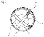
Fig. 7 ist eine zweite räumliche Darstellung des Stellantriebs 10 aus einer anderenPerspektive. Hier sind die Reib-Verstellelemente 3a, 3b um das erste Element 1herumgelegt und mit dem zweiten Element 2 verbunden, dabei sind die Reib-Verstellelementeso geführt, daß sie sich nicht gegenseitig behindern können. Weiterkönnen Befestigungsmittel in Form von Befestigungsaugen zur Befestigung desStellantriebes an ein karosseriefestes Teil dienen.7 is a second spatial representation of the actuator 10 from anotherPerspective. Here are the
Fig. 8 zeigt eine vereinfachte Schnittdarstellung des Stellantriebs 10, mit dem zweiteiligenersten Element 1, dem zweiten Element 2, dem Schnittpunkt 6 der Schwenkachsen 5a, 5b,dem Antrieb 9 mit dem Getriebemittel 18, das über eine Ausnehmung 17 in einer Wandung16 des ersten Elements 1 in den verzahnten Bereich des Reib-Verstellelements 3a eingreift,wobei das Reib-Verstellelement 3a um das erste Element 1, das zumindest teilweisekugelförmig und/oder zylinderförmig geformt ist, herumgelegt ist und über dieVerbindungsstellen 4a, 4b mit dem zweiten Element verbunden ist. Fig. 8 zeigt weiter dasSchwenklager 24 mit einer Kalotte 25 und die Halterungen 7 für das Stellglied 8 am zweitenElement 2, sowie eine Positionsermittlungseinrichtung 20, die teilweise aus dem Reib-Verstellelement3a oder einem daran befestigten Teil, z.B. einen Schleifer 33, das durcheine Ausnehmung 19 in der Wandung 16 geführt wird und einem fest im ersten Element 1montierten Bauteil, z.B. einer Leiterplatte 32 mit Potentiometerbahnen besteht. Dieelektrischen Verbindungen zu einem Anschluß 21 kann über Leitbleche 22 erfolgen, diebeispielsweise im ersten Element 1 eingespritzt sind.Fig. 8 shows a simplified sectional view of the
Fig. 9 zeigt eine zweite Ausführungsform der Erfindung, bei der eine aus einer Vielzahl vonKettengliedern 13 bestehende Kette 12, z.B. eine Kugelkette als Reib-Verstellelement 3a,3b verwendet wird, wobei die Kettenglieder durch ihre Formgebung eine Verzahnung bildenin die das Getriebemittel 18 direkt eingreift.Fig. 9 shows a second embodiment of the invention in which one of a plurality ofChain links 13 existing
Fig. 10 zeigt eine Variante des zweiten Elements 2, in dessen ringförmigem/ringförmigerRand/Wandung 14 Freisparungen 34 eingeformt sind, wodurch Federmittel 35 entstehen,die mit den Verbindungsmitteln 4a, 4b, 4c, 4d versehen sind. Auf diese Weise kann auf diefedernden Bereiche der Reib-Verstellelemente verzichtet werden.Fig. 10 shows a variant of the
Fig. 11 zeigt eine Außenansicht des Stellantriebs, mit dem ersten Element 1, das nutartigeFührungen 38 aufweist, in denen die Reib-Verstellelemente 3a, 3b verlaufen, deren Endenüber die Verbindungsstellen 4b, 4d mit dem zweiten Element 2 in Verbindung stehen.Fig. 11 shows an external view of the actuator, with the
Fig. 12 zeigt eine erste Ausführungsform einer Abstützung für das Reib-Verstellelement 3ain Form von Schnappverbindungen 39. Die Schnappverbindungen sind dabei imEingriffsbereich des Getriebemittels 18 in den verzahnten Bereich des Reib-Verstellelementsangeordnet In Fig. 13 ist eine zweite Ausführungsform der Abstützung38a dargestellt, die dabei als Steg ausgebildet ist, der die beiden Führungen 36 miteinanderverbindet. In Fig. 14 ist eine dritte Ausführungsform der Abstützung 38a dargestellt, bei derein Steg mit einer der Führungen 36 über ein Filmscharnier 40 und mit der zweiten Führung36 über eine Schnappverbindung verbunden ist. Eine vierte Ausführungsform derAbstützung zeigt Fig. 15, dabei ist die Abstützung 38b mit dem zweiten Element 2einstückig.12 shows a first embodiment of a support for the
- 11
- erstes Elementfirst element
- 22nd
- zweites Elementsecond element
- 3a, 3b3a, 3b
- Reib-VerstellelementFriction adjusting element
- 4a, 4b, 4c, 4d4a, 4b, 4c, 4d
- VerbindungsstellenJoints
- 5a, 5b5a, 5b
- SchwenkachsenSwivel axes
- 66
- Schnittpunkt der SchwenkachsenIntersection of the swivel axes
- 77
- Halterung für StellgliedBracket for actuator
- 88th
- StellgliedActuator
- 99
- Antriebdrive
- 1010th
- StellantriebActuator
- 1111
- verzahnter Bereichtoothed area
- 1212th
- KetteChain
- 1313
- KettengliederChain links
- 1414
- ringförmiger Rand/ringförmigeWandungannular rim / wall
- 15a, 15b, 15c, 15d15a, 15b, 15c, 15d
- MitnehmerCarrier
- 1616
- WandungWall
- 1717th
- Ausnehmungen für GetriebemittelRecesses for gear means
- 1818th
- GetriebemittelGear means
- 1919th
- Ausnehmungen für PositionsermittlungseinrichtungRecesses for position determination device
- 2020th
- PositionsermittlungseinrichtungPosition determination device
- 2121
- Anschlüsseconnections
- 2222
- LeitblecheBaffles
- 2323
- federnder Bereich der Reib-Verstellelementeresilient area of the friction adjustment elements
- 2424th
- SchwenklagerSwivel bearing
- 2525th
- KalotteCalotte
- 2626
- eingeprägte Verzahnungembossed toothing
- 2727
- LochungPerforation
- 2828
- VerbindungsöffnungConnection opening
- 2929
- VerstrebungenStruts
- 3030th
- NutGroove
- 3232
- LeiterplatteCircuit board
- 3333
- Schleifergrinder
- 3434
- FreisparungenExemptions
- 3535
- FedermittelSpring means
- 3636
- Führungenguides
- 3737
- Spielgame
- 38a, 38b38a, 38b
- AbstützungSupport
- 3939
- SchnappverbindungSnap connection
- 4040
- FilmscharnierFilm hinge
Claims (56)
Translated fromGermanApplications Claiming Priority (2)
| Application Number | Priority Date | Filing Date | Title |
|---|---|---|---|
| DE19919529 | 1999-04-29 | ||
| DE19919529ADE19919529B4 (en) | 1999-01-25 | 1999-04-29 | Actuator for a motor vehicle |
Publications (2)
| Publication Number | Publication Date |
|---|---|
| EP1063125A1true EP1063125A1 (en) | 2000-12-27 |
| EP1063125B1 EP1063125B1 (en) | 2002-07-24 |
Family
ID=7906296
Family Applications (1)
| Application Number | Title | Priority Date | Filing Date |
|---|---|---|---|
| EP00108886AExpired - LifetimeEP1063125B1 (en) | 1999-04-29 | 2000-04-27 | Actuator for a motor vehicle |
Country Status (2)
| Country | Link |
|---|---|
| US (1) | US6341536B1 (en) |
| EP (1) | EP1063125B1 (en) |
Cited By (1)
| Publication number | Priority date | Publication date | Assignee | Title |
|---|---|---|---|---|
| WO2003035432A1 (en)* | 2001-10-25 | 2003-05-01 | Em Kunststofftechnik Gmbh | Drive arrangement for controlled multi-axis adjustment in particular of a motor vehicle rear-view mirror |
Families Citing this family (10)
| Publication number | Priority date | Publication date | Assignee | Title |
|---|---|---|---|---|
| DE29923786U1 (en)* | 1999-07-21 | 2001-04-19 | Magna Auteca Zweigniederlassung Der Magna Holding Ag, Weiz | Drive device for an adjustable rearview mirror with a self-calibrating potentiometer |
| NL1015428C2 (en)* | 2000-06-14 | 2001-12-17 | Iku Holding Montfoort Bv | Movement mechanism. |
| DE10058730A1 (en)* | 2000-11-25 | 2003-01-02 | Buhler Motor Gmbh | Adjustment device for motor vehicle exterior mirrors |
| ES2227173T3 (en)* | 2001-03-12 | 2005-04-01 | Oechsler Aktiengesellschaft | ROTATING MOTOR INSTALLATION FOR A SUPPORT PLATE, ESPECIALLY FOR THE ACCOMMODATION OF A CAR MIRROR. |
| US20040207940A1 (en)* | 2003-04-02 | 2004-10-21 | Carter John W | Interior rearview mirror with magnesium components |
| EP2415640B1 (en)* | 2010-08-03 | 2013-02-13 | SMR Patents S.à.r.l. | External rear view mirror and method for fitting same |
| KR101652889B1 (en)* | 2015-03-13 | 2016-09-01 | 주식회사 호영자동차부품 | Apparatus for adjusting outside rear view mirror for vehicle |
| DE202019100579U1 (en)* | 2019-01-31 | 2019-02-25 | Mci (Mirror Controls International) Netherlands B.V. | Sichteinstellmechanismus |
| DE102019108303B4 (en)* | 2019-03-29 | 2020-12-10 | Mci (Mirror Controls International) Netherlands B.V. | Vision adjustment mechanism and adjusting means for such |
| DE102019215213B3 (en)* | 2019-10-02 | 2020-10-01 | Festo Se & Co. Kg | Joint device |
Citations (5)
| Publication number | Priority date | Publication date | Assignee | Title |
|---|---|---|---|---|
| DE2453498A1 (en)* | 1974-11-12 | 1976-05-13 | Ymos Metallwerke Wolf & Becker | Wing mirror with remote adjustment - using two orthogonal cables and separate electric servo motors |
| US4116538A (en)* | 1977-01-10 | 1978-09-26 | Industrie Koot B.V. | Motor-car mirror adjustable about two perpendicular axes |
| DE3026561A1 (en)* | 1979-07-26 | 1981-02-12 | Koot Ind Bv | MIRROR ADJUSTMENT DEVICE FOR MOTOR VEHICLE MIRRORS |
| US5467230A (en)* | 1993-08-16 | 1995-11-14 | Lowell Engineering Corp. | Dual pivoted member mount for mirror |
| WO1998031565A1 (en)* | 1997-01-17 | 1998-07-23 | Magna Reflex Holding Gmbh | Adjustable rear-view mirror for a vehicle |
Family Cites Families (5)
| Publication number | Priority date | Publication date | Assignee | Title |
|---|---|---|---|---|
| US4101206A (en) | 1976-04-09 | 1978-07-18 | Industrie Koot B.V. | Adjustable motor car mirror with compact electrically driven adjusting means |
| US4628760A (en)* | 1983-01-17 | 1986-12-16 | Harman Automotive, Inc. | Remote control rearview mirror and pivot |
| JPS6231540A (en)* | 1985-08-05 | 1987-02-10 | Honda Motor Co Ltd | How to drive an automobile mirror |
| BR9702665A (en)* | 1997-07-28 | 1999-10-05 | Metagal Ind Stria E Comercio L | Multipurpose joint for external rear-view mirrors |
| NL1007139C2 (en)* | 1997-09-26 | 1999-03-29 | Iku Holding Montfoort Bv | Actuator. |
- 2000
- 2000-04-26USUS09/559,398patent/US6341536B1/ennot_activeExpired - Fee Related
- 2000-04-27EPEP00108886Apatent/EP1063125B1/ennot_activeExpired - Lifetime
Patent Citations (5)
| Publication number | Priority date | Publication date | Assignee | Title |
|---|---|---|---|---|
| DE2453498A1 (en)* | 1974-11-12 | 1976-05-13 | Ymos Metallwerke Wolf & Becker | Wing mirror with remote adjustment - using two orthogonal cables and separate electric servo motors |
| US4116538A (en)* | 1977-01-10 | 1978-09-26 | Industrie Koot B.V. | Motor-car mirror adjustable about two perpendicular axes |
| DE3026561A1 (en)* | 1979-07-26 | 1981-02-12 | Koot Ind Bv | MIRROR ADJUSTMENT DEVICE FOR MOTOR VEHICLE MIRRORS |
| US5467230A (en)* | 1993-08-16 | 1995-11-14 | Lowell Engineering Corp. | Dual pivoted member mount for mirror |
| WO1998031565A1 (en)* | 1997-01-17 | 1998-07-23 | Magna Reflex Holding Gmbh | Adjustable rear-view mirror for a vehicle |
Cited By (1)
| Publication number | Priority date | Publication date | Assignee | Title |
|---|---|---|---|---|
| WO2003035432A1 (en)* | 2001-10-25 | 2003-05-01 | Em Kunststofftechnik Gmbh | Drive arrangement for controlled multi-axis adjustment in particular of a motor vehicle rear-view mirror |
Also Published As
| Publication number | Publication date |
|---|---|
| EP1063125B1 (en) | 2002-07-24 |
| US6341536B1 (en) | 2002-01-29 |
Similar Documents
| Publication | Publication Date | Title |
|---|---|---|
| DE60123923T2 (en) | ELECTROMECHANICAL OPERATING DEVICE | |
| DE3882896T2 (en) | Electrically swiveling door mirror. | |
| DE3026561C2 (en) | ||
| DE69504907T2 (en) | Adjustment device of the mirror housing of a vehicle rear view mirror. | |
| DE10238750A1 (en) | Driven carriage device for a seat | |
| DE19919529B4 (en) | Actuator for a motor vehicle | |
| EP1063125B1 (en) | Actuator for a motor vehicle | |
| DE10318616B4 (en) | Opening and closing device | |
| DE3421795A1 (en) | SWIVELING STEERING UNIT | |
| DE4115876A1 (en) | VEHICLE EXTERIOR MIRRORS | |
| WO2005039020A1 (en) | Vibration-damping receiving element | |
| DE69912396T2 (en) | CONTROL DEVICE | |
| DE19912755A1 (en) | Drive device to adjust mirror glass carrier located in pivoted fashion in mirror housing of car's rear view mirror | |
| DE69806775T2 (en) | CONTROL DEVICE | |
| DE10042678C2 (en) | Device for moving a body, in particular a vehicle part and preferably a vehicle mirror | |
| DE3043594A1 (en) | ELECTRICALLY ADJUSTABLE REAR VIEW MIRROR | |
| DE19847081B4 (en) | Manual actuator acting on both sides to generate a rotary movement | |
| DE2644074A1 (en) | DEVICE FOR SWIVELING A MIRROR, IN PARTICULAR MOTOR VEHICLE REAR MIRROR | |
| DE2805044C3 (en) | Mechanical switching device for a gearbox | |
| DE102017222976A1 (en) | Electrically adjustable steering column for a motor vehicle | |
| DE202009000982U1 (en) | Apparatus adapted to pivotally attach a screen to a wall and a related method | |
| DE69511645T2 (en) | DAMPING FLYWHEEL, ESPECIALLY FOR MOTOR VEHICLES | |
| DE102016215744A1 (en) | industrial robots | |
| EP2277210B1 (en) | Rotational drive | |
| DE102010048601A1 (en) | Input device with variable actuation feeling |
Legal Events
| Date | Code | Title | Description |
|---|---|---|---|
| PUAI | Public reference made under article 153(3) epc to a published international application that has entered the european phase | Free format text:ORIGINAL CODE: 0009012 | |
| AK | Designated contracting states | Kind code of ref document:A1 Designated state(s):FR GB | |
| AX | Request for extension of the european patent | Free format text:AL;LT;LV;MK;RO;SI | |
| 17P | Request for examination filed | Effective date:20001212 | |
| AKX | Designation fees paid | ||
| RBV | Designated contracting states (corrected) | Designated state(s):FR GB | |
| GRAG | Despatch of communication of intention to grant | Free format text:ORIGINAL CODE: EPIDOS AGRA | |
| GRAG | Despatch of communication of intention to grant | Free format text:ORIGINAL CODE: EPIDOS AGRA | |
| GRAH | Despatch of communication of intention to grant a patent | Free format text:ORIGINAL CODE: EPIDOS IGRA | |
| 17Q | First examination report despatched | Effective date:20011227 | |
| GRAH | Despatch of communication of intention to grant a patent | Free format text:ORIGINAL CODE: EPIDOS IGRA | |
| REG | Reference to a national code | Ref country code:DE Ref legal event code:8566 | |
| GRAA | (expected) grant | Free format text:ORIGINAL CODE: 0009210 | |
| AK | Designated contracting states | Kind code of ref document:B1 Designated state(s):FR GB | |
| REG | Reference to a national code | Ref country code:GB Ref legal event code:FG4D Free format text:NOT ENGLISH | |
| GBT | Gb: translation of ep patent filed (gb section 77(6)(a)/1977) | Effective date:20020813 | |
| ET | Fr: translation filed | ||
| PLBE | No opposition filed within time limit | Free format text:ORIGINAL CODE: 0009261 | |
| STAA | Information on the status of an ep patent application or granted ep patent | Free format text:STATUS: NO OPPOSITION FILED WITHIN TIME LIMIT | |
| 26N | No opposition filed | Effective date:20030425 | |
| PGFP | Annual fee paid to national office [announced via postgrant information from national office to epo] | Ref country code:GB Payment date:20080430 Year of fee payment:9 | |
| PGFP | Annual fee paid to national office [announced via postgrant information from national office to epo] | Ref country code:FR Payment date:20090212 Year of fee payment:10 | |
| GBPC | Gb: european patent ceased through non-payment of renewal fee | Effective date:20090427 | |
| PG25 | Lapsed in a contracting state [announced via postgrant information from national office to epo] | Ref country code:GB Free format text:LAPSE BECAUSE OF NON-PAYMENT OF DUE FEES Effective date:20090427 | |
| REG | Reference to a national code | Ref country code:FR Ref legal event code:ST Effective date:20101230 | |
| PG25 | Lapsed in a contracting state [announced via postgrant information from national office to epo] | Ref country code:FR Free format text:LAPSE BECAUSE OF NON-PAYMENT OF DUE FEES Effective date:20100430 |