EP1061857B1 - Systems for electrosurgical spine surgery - Google Patents
Systems for electrosurgical spine surgeryDownload PDFInfo
- Publication number
- EP1061857B1 EP1061857B1EP99934236AEP99934236AEP1061857B1EP 1061857 B1EP1061857 B1EP 1061857B1EP 99934236 AEP99934236 AEP 99934236AEP 99934236 AEP99934236 AEP 99934236AEP 1061857 B1EP1061857 B1EP 1061857B1
- Authority
- EP
- European Patent Office
- Prior art keywords
- electrode
- tissue
- shaft
- fluid
- probe
- Prior art date
- Legal status (The legal status is an assumption and is not a legal conclusion. Google has not performed a legal analysis and makes no representation as to the accuracy of the status listed.)
- Expired - Lifetime
Links
- 238000001356surgical procedureMethods0.000titledescription18
- 239000012530fluidSubstances0.000claimsabstractdescription139
- 102000008186CollagenHuman genes0.000claimsabstractdescription39
- 108010035532CollagenProteins0.000claimsabstractdescription39
- 229920001436collagenPolymers0.000claimsabstractdescription39
- 239000000523sampleSubstances0.000claimsdescription147
- 239000000919ceramicSubstances0.000claimsdescription14
- 239000012634fragmentSubstances0.000claimsdescription14
- 239000000463materialSubstances0.000claimsdescription13
- WFKWXMTUELFFGS-UHFFFAOYSA-NtungstenChemical compound[W]WFKWXMTUELFFGS-UHFFFAOYSA-N0.000claimsdescription9
- 229910052721tungstenInorganic materials0.000claimsdescription9
- 239000010937tungstenSubstances0.000claimsdescription9
- 231100000435percutaneous penetrationToxicity0.000claimsdescription8
- 230000008878couplingEffects0.000claimsdescription6
- 238000010168coupling processMethods0.000claimsdescription6
- 238000005859coupling reactionMethods0.000claimsdescription6
- 230000036961partial effectEffects0.000claimsdescription4
- 238000000034methodMethods0.000abstractdescription98
- 239000000835fiberSubstances0.000abstractdescription19
- 210000001032spinal nerveAnatomy0.000abstractdescription12
- 210000001519tissueAnatomy0.000description254
- 238000002679ablationMethods0.000description73
- 239000010410layerSubstances0.000description32
- 210000005036nerveAnatomy0.000description25
- 238000005345coagulationMethods0.000description19
- 230000015271coagulationEffects0.000description19
- 230000005684electric fieldEffects0.000description18
- FAPWRFPIFSIZLT-UHFFFAOYSA-MSodium chlorideChemical compound[Na+].[Cl-]FAPWRFPIFSIZLT-UHFFFAOYSA-M0.000description17
- 239000000499gelSubstances0.000description17
- 210000000988bone and boneAnatomy0.000description16
- 230000008602contractionEffects0.000description16
- 238000010494dissociation reactionMethods0.000description16
- 230000005593dissociationsEffects0.000description16
- 230000000670limiting effectEffects0.000description15
- 239000007788liquidSubstances0.000description15
- 230000006378damageEffects0.000description14
- 238000010438heat treatmentMethods0.000description14
- 210000004872soft tissueAnatomy0.000description14
- 230000009467reductionEffects0.000description13
- 229910052751metalInorganic materials0.000description12
- BASFCYQUMIYNBI-UHFFFAOYSA-NplatinumChemical compound[Pt]BASFCYQUMIYNBI-UHFFFAOYSA-N0.000description12
- 230000008569processEffects0.000description12
- 230000000694effectsEffects0.000description11
- 230000005499meniscusEffects0.000description11
- 239000002184metalSubstances0.000description11
- 208000003618Intervertebral Disc DisplacementDiseases0.000description9
- 210000001188articular cartilageAnatomy0.000description9
- 239000004020conductorSubstances0.000description9
- 239000002245particleSubstances0.000description9
- 230000008016vaporizationEffects0.000description9
- 238000005520cutting processMethods0.000description8
- 230000006870functionEffects0.000description8
- RTAQQCXQSZGOHL-UHFFFAOYSA-NTitaniumChemical compound[Ti]RTAQQCXQSZGOHL-UHFFFAOYSA-N0.000description7
- 210000000577adipose tissueAnatomy0.000description7
- 230000004907fluxEffects0.000description7
- 230000007246mechanismEffects0.000description7
- 230000017074necrotic cell deathEffects0.000description7
- 230000035515penetrationEffects0.000description7
- 239000011780sodium chlorideSubstances0.000description7
- 125000006850spacer groupChemical group0.000description7
- 239000010936titaniumSubstances0.000description7
- 229910052719titaniumInorganic materials0.000description7
- 238000009834vaporizationMethods0.000description7
- PXHVJJICTQNCMI-UHFFFAOYSA-NNickelChemical compound[Ni]PXHVJJICTQNCMI-UHFFFAOYSA-N0.000description6
- 229910045601alloyInorganic materials0.000description6
- 239000000956alloySubstances0.000description6
- PNEYBMLMFCGWSK-UHFFFAOYSA-Naluminium oxideInorganic materials[O-2].[O-2].[O-2].[Al+3].[Al+3]PNEYBMLMFCGWSK-UHFFFAOYSA-N0.000description6
- 210000004204blood vesselAnatomy0.000description6
- 239000003990capacitorSubstances0.000description6
- 230000001965increasing effectEffects0.000description6
- 210000003205muscleAnatomy0.000description6
- 229910052697platinumInorganic materials0.000description6
- 230000004927fusionEffects0.000description5
- 239000007789gasSubstances0.000description5
- 230000023597hemostasisEffects0.000description5
- 210000003041ligamentAnatomy0.000description5
- RYGMFSIKBFXOCR-UHFFFAOYSA-NCopperChemical compound[Cu]RYGMFSIKBFXOCR-UHFFFAOYSA-N0.000description4
- 241000283984RodentiaSpecies0.000description4
- MCMNRKCIXSYSNV-UHFFFAOYSA-NZirconium dioxideChemical compoundO=[Zr]=OMCMNRKCIXSYSNV-UHFFFAOYSA-N0.000description4
- 210000001015abdomenAnatomy0.000description4
- 230000000740bleeding effectEffects0.000description4
- 239000008280bloodSubstances0.000description4
- 210000004369bloodAnatomy0.000description4
- 210000000845cartilageAnatomy0.000description4
- 210000002808connective tissueAnatomy0.000description4
- 229910052802copperInorganic materials0.000description4
- 239000010949copperSubstances0.000description4
- 239000011521glassSubstances0.000description4
- PCHJSUWPFVWCPO-UHFFFAOYSA-NgoldChemical compound[Au]PCHJSUWPFVWCPO-UHFFFAOYSA-N0.000description4
- 229910052737goldInorganic materials0.000description4
- 239000010931goldSubstances0.000description4
- 239000007943implantSubstances0.000description4
- 210000004126nerve fiberAnatomy0.000description4
- 230000001817pituitary effectEffects0.000description4
- 239000007921spraySubstances0.000description4
- 208000008035Back PainDiseases0.000description3
- OKTJSMMVPCPJKN-UHFFFAOYSA-NCarbonChemical compound[C]OKTJSMMVPCPJKN-UHFFFAOYSA-N0.000description3
- 206010016654FibrosisDiseases0.000description3
- 206010050296Intervertebral disc protrusionDiseases0.000description3
- 229910000831SteelInorganic materials0.000description3
- 208000027418Wounds and injuryDiseases0.000description3
- 230000008901benefitEffects0.000description3
- 230000015572biosynthetic processEffects0.000description3
- 230000036760body temperatureEffects0.000description3
- 229910052799carbonInorganic materials0.000description3
- 230000015556catabolic processEffects0.000description3
- 238000000576coating methodMethods0.000description3
- 230000004761fibrosisEffects0.000description3
- 230000002401inhibitory effectEffects0.000description3
- 208000014674injuryDiseases0.000description3
- 210000002414legAnatomy0.000description3
- 230000033001locomotionEffects0.000description3
- 229910052759nickelInorganic materials0.000description3
- 238000007789sealingMethods0.000description3
- 239000003566sealing materialSubstances0.000description3
- 210000000278spinal cordAnatomy0.000description3
- 229910001220stainless steelInorganic materials0.000description3
- 239000010935stainless steelSubstances0.000description3
- 239000010959steelSubstances0.000description3
- 229910052715tantalumInorganic materials0.000description3
- GUVRBAGPIYLISA-UHFFFAOYSA-Ntantalum atomChemical compound[Ta]GUVRBAGPIYLISA-UHFFFAOYSA-N0.000description3
- 238000012800visualizationMethods0.000description3
- XKRFYHLGVUSROY-UHFFFAOYSA-NArgonChemical compound[Ar]XKRFYHLGVUSROY-UHFFFAOYSA-N0.000description2
- IJGRMHOSHXDMSA-UHFFFAOYSA-NAtomic nitrogenChemical compoundN#NIJGRMHOSHXDMSA-UHFFFAOYSA-N0.000description2
- CURLTUGMZLYLDI-UHFFFAOYSA-NCarbon dioxideChemical compoundO=C=OCURLTUGMZLYLDI-UHFFFAOYSA-N0.000description2
- 206010061213Iatrogenic injuryDiseases0.000description2
- 206010061218InflammationDiseases0.000description2
- XEEYBQQBJWHFJM-UHFFFAOYSA-NIronChemical compound[Fe]XEEYBQQBJWHFJM-UHFFFAOYSA-N0.000description2
- ZOKXTWBITQBERF-UHFFFAOYSA-NMolybdenumChemical compound[Mo]ZOKXTWBITQBERF-UHFFFAOYSA-N0.000description2
- KDLHZDBZIXYQEI-UHFFFAOYSA-NPalladiumChemical compound[Pd]KDLHZDBZIXYQEI-UHFFFAOYSA-N0.000description2
- 208000020307Spinal diseaseDiseases0.000description2
- 239000000853adhesiveSubstances0.000description2
- 230000001070adhesive effectEffects0.000description2
- 238000013459approachMethods0.000description2
- 238000005422blastingMethods0.000description2
- 210000004027cellAnatomy0.000description2
- 230000008859changeEffects0.000description2
- 210000000038chestAnatomy0.000description2
- 239000011248coating agentSubstances0.000description2
- 230000003412degenerative effectEffects0.000description2
- 210000001951dura materAnatomy0.000description2
- 239000012777electrically insulating materialSubstances0.000description2
- 239000003792electrolyteSubstances0.000description2
- 229920006332epoxy adhesivePolymers0.000description2
- 238000005530etchingMethods0.000description2
- 238000011065in-situ storageMethods0.000description2
- 230000001939inductive effectEffects0.000description2
- 230000004054inflammatory processEffects0.000description2
- 238000009413insulationMethods0.000description2
- 210000003127kneeAnatomy0.000description2
- 210000000629knee jointAnatomy0.000description2
- 238000002684laminectomyMethods0.000description2
- WABPQHHGFIMREM-UHFFFAOYSA-Nlead(0)Chemical compound[Pb]WABPQHHGFIMREM-UHFFFAOYSA-N0.000description2
- 238000004519manufacturing processMethods0.000description2
- 239000011159matrix materialSubstances0.000description2
- 230000008018meltingEffects0.000description2
- 238000002844meltingMethods0.000description2
- VNWKTOKETHGBQD-UHFFFAOYSA-NmethaneChemical compoundCVNWKTOKETHGBQD-UHFFFAOYSA-N0.000description2
- 238000012986modificationMethods0.000description2
- 230000004048modificationEffects0.000description2
- 229910052750molybdenumInorganic materials0.000description2
- 239000011733molybdenumSubstances0.000description2
- 230000002093peripheral effectEffects0.000description2
- 210000000578peripheral nerveAnatomy0.000description2
- 239000004033plasticSubstances0.000description2
- 230000008439repair processEffects0.000description2
- 238000011160researchMethods0.000description2
- 238000002271resectionMethods0.000description2
- 238000007493shaping processMethods0.000description2
- 239000007787solidSubstances0.000description2
- 241000894007speciesSpecies0.000description2
- 230000000087stabilizing effectEffects0.000description2
- 239000000126substanceSubstances0.000description2
- 239000000758substrateSubstances0.000description2
- 239000002344surface layerSubstances0.000description2
- 230000001225therapeutic effectEffects0.000description2
- 230000003685thermal hair damageEffects0.000description2
- 210000000115thoracic cavityAnatomy0.000description2
- 210000002303tibiaAnatomy0.000description2
- 230000000451tissue damageEffects0.000description2
- 231100000827tissue damageToxicity0.000description2
- 230000000472traumatic effectEffects0.000description2
- 210000000689upper legAnatomy0.000description2
- XLYOFNOQVPJJNP-UHFFFAOYSA-NwaterSubstancesOXLYOFNOQVPJJNP-UHFFFAOYSA-N0.000description2
- VYZAMTAEIAYCRO-UHFFFAOYSA-NChromiumChemical compound[Cr]VYZAMTAEIAYCRO-UHFFFAOYSA-N0.000description1
- 239000004593EpoxySubstances0.000description1
- UFHFLCQGNIYNRP-UHFFFAOYSA-NHydrogenChemical compound[H][H]UFHFLCQGNIYNRP-UHFFFAOYSA-N0.000description1
- DGAQECJNVWCQMB-PUAWFVPOSA-MIlexoside XXIXChemical compoundC[C@@H]1CC[C@@]2(CC[C@@]3(C(=CC[C@H]4[C@]3(CC[C@@H]5[C@@]4(CC[C@@H](C5(C)C)OS(=O)(=O)[O-])C)C)[C@@H]2[C@]1(C)O)C)C(=O)O[C@H]6[C@@H]([C@H]([C@@H]([C@H](O6)CO)O)O)O.[Na+]DGAQECJNVWCQMB-PUAWFVPOSA-M0.000description1
- 206010061246Intervertebral disc degenerationDiseases0.000description1
- 206010028980NeoplasmDiseases0.000description1
- 208000028389Nerve injuryDiseases0.000description1
- 208000031264Nerve root compressionDiseases0.000description1
- 208000002193PainDiseases0.000description1
- 206010033425Pain in extremityDiseases0.000description1
- 208000031481Pathologic ConstrictionDiseases0.000description1
- 239000004642PolyimideSubstances0.000description1
- 206010036940Prostatic adenomaDiseases0.000description1
- 206010037779RadiculopathyDiseases0.000description1
- BQCADISMDOOEFD-UHFFFAOYSA-NSilverChemical compound[Ag]BQCADISMDOOEFD-UHFFFAOYSA-N0.000description1
- 208000007097Urinary Bladder NeoplasmsDiseases0.000description1
- 238000010521absorption reactionMethods0.000description1
- 230000003213activating effectEffects0.000description1
- 229910052782aluminiumInorganic materials0.000description1
- XAGFODPZIPBFFR-UHFFFAOYSA-NaluminiumChemical compound[Al]XAGFODPZIPBFFR-UHFFFAOYSA-N0.000description1
- 238000004458analytical methodMethods0.000description1
- 230000003110anti-inflammatory effectEffects0.000description1
- 239000007864aqueous solutionSubstances0.000description1
- 229910052786argonInorganic materials0.000description1
- 238000003491arrayMethods0.000description1
- QVGXLLKOCUKJST-UHFFFAOYSA-Natomic oxygenChemical compound[O]QVGXLLKOCUKJST-UHFFFAOYSA-N0.000description1
- 229910000963austenitic stainless steelInorganic materials0.000description1
- 238000005452bendingMethods0.000description1
- 230000005540biological transmissionEffects0.000description1
- 239000001569carbon dioxideSubstances0.000description1
- 229910002092carbon dioxideInorganic materials0.000description1
- 238000003763carbonizationMethods0.000description1
- 210000000170cell membraneAnatomy0.000description1
- 230000001413cellular effectEffects0.000description1
- 229910010293ceramic materialInorganic materials0.000description1
- 238000006243chemical reactionMethods0.000description1
- 229910052804chromiumInorganic materials0.000description1
- 239000011651chromiumSubstances0.000description1
- 208000037976chronic inflammationDiseases0.000description1
- 230000006020chronic inflammationEffects0.000description1
- 229910017052cobaltInorganic materials0.000description1
- 239000010941cobaltSubstances0.000description1
- GUTLYIVDDKVIGB-UHFFFAOYSA-Ncobalt atomChemical compound[Co]GUTLYIVDDKVIGB-UHFFFAOYSA-N0.000description1
- 238000004891communicationMethods0.000description1
- 238000010276constructionMethods0.000description1
- 238000007796conventional methodMethods0.000description1
- 239000003246corticosteroidSubstances0.000description1
- 229960001334corticosteroidsDrugs0.000description1
- 210000003792cranial nerveAnatomy0.000description1
- 230000001186cumulative effectEffects0.000description1
- 230000000991decompressive effectEffects0.000description1
- 238000013461designMethods0.000description1
- 238000002224dissectionMethods0.000description1
- 239000003814drugSubstances0.000description1
- 229940079593drugDrugs0.000description1
- 238000010292electrical insulationMethods0.000description1
- 239000007772electrode materialSubstances0.000description1
- 238000002674endoscopic surgeryMethods0.000description1
- 238000002594fluoroscopyMethods0.000description1
- 239000003574free electronSubstances0.000description1
- 210000004907glandAnatomy0.000description1
- 239000006112glass ceramic compositionSubstances0.000description1
- 239000002241glass-ceramicSubstances0.000description1
- 230000035876healingEffects0.000description1
- 229930195733hydrocarbonNatural products0.000description1
- 150000002430hydrocarbonsChemical class0.000description1
- 239000001257hydrogenSubstances0.000description1
- 229910052739hydrogenInorganic materials0.000description1
- 230000002706hydrostatic effectEffects0.000description1
- 238000005286illuminationMethods0.000description1
- 238000013383initial experimentMethods0.000description1
- 238000002347injectionMethods0.000description1
- 239000007924injectionSubstances0.000description1
- 238000003780insertionMethods0.000description1
- 230000037431insertionEffects0.000description1
- 239000011810insulating materialSubstances0.000description1
- 239000012212insulatorSubstances0.000description1
- 229910052742ironInorganic materials0.000description1
- 230000001788irregularEffects0.000description1
- 230000002427irreversible effectEffects0.000description1
- 230000002262irrigationEffects0.000description1
- 238000003973irrigationMethods0.000description1
- 238000005304joiningMethods0.000description1
- 230000003155kinesthetic effectEffects0.000description1
- 201000010260leiomyomaDiseases0.000description1
- 230000013011matingEffects0.000description1
- 238000002483medicationMethods0.000description1
- 239000007769metal materialSubstances0.000description1
- 150000002739metalsChemical class0.000description1
- 210000003097mucusAnatomy0.000description1
- 230000008764nerve damageEffects0.000description1
- 210000000944nerve tissueAnatomy0.000description1
- 208000015122neurodegenerative diseaseDiseases0.000description1
- 229910052757nitrogenInorganic materials0.000description1
- 229910017464nitrogen compoundInorganic materials0.000description1
- 150000002830nitrogen compoundsChemical class0.000description1
- 231100000862numbnessToxicity0.000description1
- 230000003287optical effectEffects0.000description1
- 239000001301oxygenSubstances0.000description1
- 229910052760oxygenInorganic materials0.000description1
- 229910052763palladiumInorganic materials0.000description1
- 230000002085persistent effectEffects0.000description1
- 230000010287polarizationEffects0.000description1
- 229920001721polyimidePolymers0.000description1
- -1polytetrafluoroethylenePolymers0.000description1
- 229920001343polytetrafluoroethylenePolymers0.000description1
- 239000004810polytetrafluoroethyleneSubstances0.000description1
- 238000002360preparation methodMethods0.000description1
- 230000001681protective effectEffects0.000description1
- 238000005086pumpingMethods0.000description1
- 230000005855radiationEffects0.000description1
- 238000011084recoveryMethods0.000description1
- 230000001172regenerating effectEffects0.000description1
- 230000004044responseEffects0.000description1
- 230000037390scarringEffects0.000description1
- 206010039722scoliosisDiseases0.000description1
- 230000035939shockEffects0.000description1
- 239000002210silicon-based materialSubstances0.000description1
- 229910052709silverInorganic materials0.000description1
- 239000004332silverSubstances0.000description1
- 239000002356single layerSubstances0.000description1
- 229910052708sodiumInorganic materials0.000description1
- 239000011734sodiumSubstances0.000description1
- 238000010186stainingMethods0.000description1
- 229910001256stainless steel alloyInorganic materials0.000description1
- 230000036262stenosisEffects0.000description1
- 208000037804stenosisDiseases0.000description1
- 230000000638stimulationEffects0.000description1
- 238000000859sublimationMethods0.000description1
- 230000008022sublimationEffects0.000description1
- 230000003746surface roughnessEffects0.000description1
- 230000008961swellingEffects0.000description1
- 210000002435tendonAnatomy0.000description1
- 238000002207thermal evaporationMethods0.000description1
- 238000012876topographyMethods0.000description1
- 238000002604ultrasonographyMethods0.000description1
- 210000003462veinAnatomy0.000description1
- 208000029761vertebral diseaseDiseases0.000description1
- 230000003313weakening effectEffects0.000description1
Images


Classifications
- A—HUMAN NECESSITIES
- A61—MEDICAL OR VETERINARY SCIENCE; HYGIENE
- A61B—DIAGNOSIS; SURGERY; IDENTIFICATION
- A61B18/00—Surgical instruments, devices or methods for transferring non-mechanical forms of energy to or from the body
- A61B18/04—Surgical instruments, devices or methods for transferring non-mechanical forms of energy to or from the body by heating
- A61B18/12—Surgical instruments, devices or methods for transferring non-mechanical forms of energy to or from the body by heating by passing a current through the tissue to be heated, e.g. high-frequency current
- A61B18/14—Probes or electrodes therefor
- A61B18/148—Probes or electrodes therefor having a short, rigid shaft for accessing the inner body transcutaneously, e.g. for neurosurgery or arthroscopy
- A—HUMAN NECESSITIES
- A61—MEDICAL OR VETERINARY SCIENCE; HYGIENE
- A61B—DIAGNOSIS; SURGERY; IDENTIFICATION
- A61B18/00—Surgical instruments, devices or methods for transferring non-mechanical forms of energy to or from the body
- A61B18/04—Surgical instruments, devices or methods for transferring non-mechanical forms of energy to or from the body by heating
- A61B18/12—Surgical instruments, devices or methods for transferring non-mechanical forms of energy to or from the body by heating by passing a current through the tissue to be heated, e.g. high-frequency current
- A61B18/1206—Generators therefor
- A—HUMAN NECESSITIES
- A61—MEDICAL OR VETERINARY SCIENCE; HYGIENE
- A61B—DIAGNOSIS; SURGERY; IDENTIFICATION
- A61B18/00—Surgical instruments, devices or methods for transferring non-mechanical forms of energy to or from the body
- A61B18/04—Surgical instruments, devices or methods for transferring non-mechanical forms of energy to or from the body by heating
- A61B18/12—Surgical instruments, devices or methods for transferring non-mechanical forms of energy to or from the body by heating by passing a current through the tissue to be heated, e.g. high-frequency current
- A61B18/14—Probes or electrodes therefor
- A61B18/1402—Probes for open surgery
- A—HUMAN NECESSITIES
- A61—MEDICAL OR VETERINARY SCIENCE; HYGIENE
- A61B—DIAGNOSIS; SURGERY; IDENTIFICATION
- A61B18/00—Surgical instruments, devices or methods for transferring non-mechanical forms of energy to or from the body
- A61B18/04—Surgical instruments, devices or methods for transferring non-mechanical forms of energy to or from the body by heating
- A61B18/12—Surgical instruments, devices or methods for transferring non-mechanical forms of energy to or from the body by heating by passing a current through the tissue to be heated, e.g. high-frequency current
- A61B18/14—Probes or electrodes therefor
- A61B18/1482—Probes or electrodes therefor having a long rigid shaft for accessing the inner body transcutaneously in minimal invasive surgery, e.g. laparoscopy
- A—HUMAN NECESSITIES
- A61—MEDICAL OR VETERINARY SCIENCE; HYGIENE
- A61B—DIAGNOSIS; SURGERY; IDENTIFICATION
- A61B18/00—Surgical instruments, devices or methods for transferring non-mechanical forms of energy to or from the body
- A61B18/04—Surgical instruments, devices or methods for transferring non-mechanical forms of energy to or from the body by heating
- A61B18/12—Surgical instruments, devices or methods for transferring non-mechanical forms of energy to or from the body by heating by passing a current through the tissue to be heated, e.g. high-frequency current
- A61B18/14—Probes or electrodes therefor
- A61B18/1485—Probes or electrodes therefor having a short rigid shaft for accessing the inner body through natural openings
- A—HUMAN NECESSITIES
- A61—MEDICAL OR VETERINARY SCIENCE; HYGIENE
- A61B—DIAGNOSIS; SURGERY; IDENTIFICATION
- A61B18/00—Surgical instruments, devices or methods for transferring non-mechanical forms of energy to or from the body
- A61B18/04—Surgical instruments, devices or methods for transferring non-mechanical forms of energy to or from the body by heating
- A61B18/12—Surgical instruments, devices or methods for transferring non-mechanical forms of energy to or from the body by heating by passing a current through the tissue to be heated, e.g. high-frequency current
- A61B18/14—Probes or electrodes therefor
- A61B18/149—Probes or electrodes therefor bow shaped or with rotatable body at cantilever end, e.g. for resectoscopes, or coagulating rollers
- A—HUMAN NECESSITIES
- A61—MEDICAL OR VETERINARY SCIENCE; HYGIENE
- A61B—DIAGNOSIS; SURGERY; IDENTIFICATION
- A61B18/00—Surgical instruments, devices or methods for transferring non-mechanical forms of energy to or from the body
- A61B18/04—Surgical instruments, devices or methods for transferring non-mechanical forms of energy to or from the body by heating
- A61B18/12—Surgical instruments, devices or methods for transferring non-mechanical forms of energy to or from the body by heating by passing a current through the tissue to be heated, e.g. high-frequency current
- A61B18/14—Probes or electrodes therefor
- A61B18/1492—Probes or electrodes therefor having a flexible, catheter-like structure, e.g. for heart ablation
- A—HUMAN NECESSITIES
- A61—MEDICAL OR VETERINARY SCIENCE; HYGIENE
- A61M—DEVICES FOR INTRODUCING MEDIA INTO, OR ONTO, THE BODY; DEVICES FOR TRANSDUCING BODY MEDIA OR FOR TAKING MEDIA FROM THE BODY; DEVICES FOR PRODUCING OR ENDING SLEEP OR STUPOR
- A61M25/00—Catheters; Hollow probes
- A61M25/01—Introducing, guiding, advancing, emplacing or holding catheters
- A61M25/0105—Steering means as part of the catheter or advancing means; Markers for positioning
- A61M25/0133—Tip steering devices
- A—HUMAN NECESSITIES
- A61—MEDICAL OR VETERINARY SCIENCE; HYGIENE
- A61B—DIAGNOSIS; SURGERY; IDENTIFICATION
- A61B18/00—Surgical instruments, devices or methods for transferring non-mechanical forms of energy to or from the body
- A61B18/04—Surgical instruments, devices or methods for transferring non-mechanical forms of energy to or from the body by heating
- A61B18/12—Surgical instruments, devices or methods for transferring non-mechanical forms of energy to or from the body by heating by passing a current through the tissue to be heated, e.g. high-frequency current
- A61B18/14—Probes or electrodes therefor
- A—HUMAN NECESSITIES
- A61—MEDICAL OR VETERINARY SCIENCE; HYGIENE
- A61B—DIAGNOSIS; SURGERY; IDENTIFICATION
- A61B17/00—Surgical instruments, devices or methods
- A61B2017/00017—Electrical control of surgical instruments
- A61B2017/00022—Sensing or detecting at the treatment site
- A61B2017/00026—Conductivity or impedance, e.g. of tissue
- A—HUMAN NECESSITIES
- A61—MEDICAL OR VETERINARY SCIENCE; HYGIENE
- A61B—DIAGNOSIS; SURGERY; IDENTIFICATION
- A61B17/00—Surgical instruments, devices or methods
- A61B2017/00017—Electrical control of surgical instruments
- A61B2017/00022—Sensing or detecting at the treatment site
- A61B2017/00084—Temperature
- A61B2017/00092—Temperature using thermocouples
- A61B2017/00097—Temperature using thermocouples one of the thermometric elements being an electrode or the heating element
- A—HUMAN NECESSITIES
- A61—MEDICAL OR VETERINARY SCIENCE; HYGIENE
- A61B—DIAGNOSIS; SURGERY; IDENTIFICATION
- A61B17/00—Surgical instruments, devices or methods
- A61B2017/00017—Electrical control of surgical instruments
- A61B2017/00022—Sensing or detecting at the treatment site
- A61B2017/00084—Temperature
- A61B2017/00101—Temperature using an array of thermosensors
- A—HUMAN NECESSITIES
- A61—MEDICAL OR VETERINARY SCIENCE; HYGIENE
- A61B—DIAGNOSIS; SURGERY; IDENTIFICATION
- A61B17/00—Surgical instruments, devices or methods
- A61B17/00234—Surgical instruments, devices or methods for minimally invasive surgery
- A61B2017/00238—Type of minimally invasive operation
- A61B2017/00243—Type of minimally invasive operation cardiac
- A61B2017/00247—Making holes in the wall of the heart, e.g. laser Myocardial revascularization
- A—HUMAN NECESSITIES
- A61—MEDICAL OR VETERINARY SCIENCE; HYGIENE
- A61B—DIAGNOSIS; SURGERY; IDENTIFICATION
- A61B17/00—Surgical instruments, devices or methods
- A61B17/00234—Surgical instruments, devices or methods for minimally invasive surgery
- A61B2017/00292—Surgical instruments, devices or methods for minimally invasive surgery mounted on or guided by flexible, e.g. catheter-like, means
- A61B2017/003—Steerable
- A—HUMAN NECESSITIES
- A61—MEDICAL OR VETERINARY SCIENCE; HYGIENE
- A61B—DIAGNOSIS; SURGERY; IDENTIFICATION
- A61B17/00—Surgical instruments, devices or methods
- A61B17/22—Implements for squeezing-off ulcers or the like on inner organs of the body; Implements for scraping-out cavities of body organs, e.g. bones; for invasive removal or destruction of calculus using mechanical vibrations; for removing obstructions in blood vessels, not otherwise provided for
- A61B2017/22001—Angioplasty, e.g. PCTA
- A—HUMAN NECESSITIES
- A61—MEDICAL OR VETERINARY SCIENCE; HYGIENE
- A61B—DIAGNOSIS; SURGERY; IDENTIFICATION
- A61B17/00—Surgical instruments, devices or methods
- A61B17/22—Implements for squeezing-off ulcers or the like on inner organs of the body; Implements for scraping-out cavities of body organs, e.g. bones; for invasive removal or destruction of calculus using mechanical vibrations; for removing obstructions in blood vessels, not otherwise provided for
- A61B2017/22038—Implements for squeezing-off ulcers or the like on inner organs of the body; Implements for scraping-out cavities of body organs, e.g. bones; for invasive removal or destruction of calculus using mechanical vibrations; for removing obstructions in blood vessels, not otherwise provided for with a guide wire
- A—HUMAN NECESSITIES
- A61—MEDICAL OR VETERINARY SCIENCE; HYGIENE
- A61B—DIAGNOSIS; SURGERY; IDENTIFICATION
- A61B18/00—Surgical instruments, devices or methods for transferring non-mechanical forms of energy to or from the body
- A61B2018/00005—Cooling or heating of the probe or tissue immediately surrounding the probe
- A61B2018/00011—Cooling or heating of the probe or tissue immediately surrounding the probe with fluids
- A61B2018/00029—Cooling or heating of the probe or tissue immediately surrounding the probe with fluids open
- A—HUMAN NECESSITIES
- A61—MEDICAL OR VETERINARY SCIENCE; HYGIENE
- A61B—DIAGNOSIS; SURGERY; IDENTIFICATION
- A61B18/00—Surgical instruments, devices or methods for transferring non-mechanical forms of energy to or from the body
- A61B2018/00053—Mechanical features of the instrument of device
- A61B2018/00059—Material properties
- A61B2018/00071—Electrical conductivity
- A61B2018/00083—Electrical conductivity low, i.e. electrically insulating
- A—HUMAN NECESSITIES
- A61—MEDICAL OR VETERINARY SCIENCE; HYGIENE
- A61B—DIAGNOSIS; SURGERY; IDENTIFICATION
- A61B18/00—Surgical instruments, devices or methods for transferring non-mechanical forms of energy to or from the body
- A61B2018/00053—Mechanical features of the instrument of device
- A61B2018/00107—Coatings on the energy applicator
- A61B2018/00119—Coatings on the energy applicator with metal oxide nitride
- A—HUMAN NECESSITIES
- A61—MEDICAL OR VETERINARY SCIENCE; HYGIENE
- A61B—DIAGNOSIS; SURGERY; IDENTIFICATION
- A61B18/00—Surgical instruments, devices or methods for transferring non-mechanical forms of energy to or from the body
- A61B2018/00053—Mechanical features of the instrument of device
- A61B2018/0016—Energy applicators arranged in a two- or three dimensional array
- A—HUMAN NECESSITIES
- A61—MEDICAL OR VETERINARY SCIENCE; HYGIENE
- A61B—DIAGNOSIS; SURGERY; IDENTIFICATION
- A61B18/00—Surgical instruments, devices or methods for transferring non-mechanical forms of energy to or from the body
- A61B2018/00053—Mechanical features of the instrument of device
- A61B2018/00172—Connectors and adapters therefor
- A61B2018/00178—Electrical connectors
- A—HUMAN NECESSITIES
- A61—MEDICAL OR VETERINARY SCIENCE; HYGIENE
- A61B—DIAGNOSIS; SURGERY; IDENTIFICATION
- A61B18/00—Surgical instruments, devices or methods for transferring non-mechanical forms of energy to or from the body
- A61B2018/00053—Mechanical features of the instrument of device
- A61B2018/00184—Moving parts
- A61B2018/00196—Moving parts reciprocating lengthwise
- A—HUMAN NECESSITIES
- A61—MEDICAL OR VETERINARY SCIENCE; HYGIENE
- A61B—DIAGNOSIS; SURGERY; IDENTIFICATION
- A61B18/00—Surgical instruments, devices or methods for transferring non-mechanical forms of energy to or from the body
- A61B2018/00315—Surgical instruments, devices or methods for transferring non-mechanical forms of energy to or from the body for treatment of particular body parts
- A61B2018/00321—Head or parts thereof
- A61B2018/00327—Ear, nose or throat
- A—HUMAN NECESSITIES
- A61—MEDICAL OR VETERINARY SCIENCE; HYGIENE
- A61B—DIAGNOSIS; SURGERY; IDENTIFICATION
- A61B18/00—Surgical instruments, devices or methods for transferring non-mechanical forms of energy to or from the body
- A61B2018/00315—Surgical instruments, devices or methods for transferring non-mechanical forms of energy to or from the body for treatment of particular body parts
- A61B2018/00345—Vascular system
- A61B2018/00351—Heart
- A61B2018/00392—Transmyocardial revascularisation
- A—HUMAN NECESSITIES
- A61—MEDICAL OR VETERINARY SCIENCE; HYGIENE
- A61B—DIAGNOSIS; SURGERY; IDENTIFICATION
- A61B18/00—Surgical instruments, devices or methods for transferring non-mechanical forms of energy to or from the body
- A61B2018/00315—Surgical instruments, devices or methods for transferring non-mechanical forms of energy to or from the body for treatment of particular body parts
- A61B2018/00434—Neural system
- A—HUMAN NECESSITIES
- A61—MEDICAL OR VETERINARY SCIENCE; HYGIENE
- A61B—DIAGNOSIS; SURGERY; IDENTIFICATION
- A61B18/00—Surgical instruments, devices or methods for transferring non-mechanical forms of energy to or from the body
- A61B2018/00315—Surgical instruments, devices or methods for transferring non-mechanical forms of energy to or from the body for treatment of particular body parts
- A61B2018/00505—Urinary tract
- A—HUMAN NECESSITIES
- A61—MEDICAL OR VETERINARY SCIENCE; HYGIENE
- A61B—DIAGNOSIS; SURGERY; IDENTIFICATION
- A61B18/00—Surgical instruments, devices or methods for transferring non-mechanical forms of energy to or from the body
- A61B2018/00571—Surgical instruments, devices or methods for transferring non-mechanical forms of energy to or from the body for achieving a particular surgical effect
- A61B2018/00577—Ablation
- A61B2018/00583—Coblation, i.e. ablation using a cold plasma
- A—HUMAN NECESSITIES
- A61—MEDICAL OR VETERINARY SCIENCE; HYGIENE
- A61B—DIAGNOSIS; SURGERY; IDENTIFICATION
- A61B18/00—Surgical instruments, devices or methods for transferring non-mechanical forms of energy to or from the body
- A61B2018/00636—Sensing and controlling the application of energy
- A61B2018/00642—Sensing and controlling the application of energy with feedback, i.e. closed loop control
- A—HUMAN NECESSITIES
- A61—MEDICAL OR VETERINARY SCIENCE; HYGIENE
- A61B—DIAGNOSIS; SURGERY; IDENTIFICATION
- A61B18/00—Surgical instruments, devices or methods for transferring non-mechanical forms of energy to or from the body
- A61B2018/00636—Sensing and controlling the application of energy
- A61B2018/0066—Sensing and controlling the application of energy without feedback, i.e. open loop control
- A—HUMAN NECESSITIES
- A61—MEDICAL OR VETERINARY SCIENCE; HYGIENE
- A61B—DIAGNOSIS; SURGERY; IDENTIFICATION
- A61B18/00—Surgical instruments, devices or methods for transferring non-mechanical forms of energy to or from the body
- A61B2018/00636—Sensing and controlling the application of energy
- A61B2018/00666—Sensing and controlling the application of energy using a threshold value
- A61B2018/00678—Sensing and controlling the application of energy using a threshold value upper
- A—HUMAN NECESSITIES
- A61—MEDICAL OR VETERINARY SCIENCE; HYGIENE
- A61B—DIAGNOSIS; SURGERY; IDENTIFICATION
- A61B18/00—Surgical instruments, devices or methods for transferring non-mechanical forms of energy to or from the body
- A61B2018/00636—Sensing and controlling the application of energy
- A61B2018/00696—Controlled or regulated parameters
- A61B2018/00702—Power or energy
- A—HUMAN NECESSITIES
- A61—MEDICAL OR VETERINARY SCIENCE; HYGIENE
- A61B—DIAGNOSIS; SURGERY; IDENTIFICATION
- A61B18/00—Surgical instruments, devices or methods for transferring non-mechanical forms of energy to or from the body
- A61B2018/00636—Sensing and controlling the application of energy
- A61B2018/00696—Controlled or regulated parameters
- A61B2018/00726—Duty cycle
- A—HUMAN NECESSITIES
- A61—MEDICAL OR VETERINARY SCIENCE; HYGIENE
- A61B—DIAGNOSIS; SURGERY; IDENTIFICATION
- A61B18/00—Surgical instruments, devices or methods for transferring non-mechanical forms of energy to or from the body
- A61B2018/00636—Sensing and controlling the application of energy
- A61B2018/00696—Controlled or regulated parameters
- A61B2018/00761—Duration
- A—HUMAN NECESSITIES
- A61—MEDICAL OR VETERINARY SCIENCE; HYGIENE
- A61B—DIAGNOSIS; SURGERY; IDENTIFICATION
- A61B18/00—Surgical instruments, devices or methods for transferring non-mechanical forms of energy to or from the body
- A61B2018/00636—Sensing and controlling the application of energy
- A61B2018/00773—Sensed parameters
- A61B2018/00791—Temperature
- A61B2018/00797—Temperature measured by multiple temperature sensors
- A—HUMAN NECESSITIES
- A61—MEDICAL OR VETERINARY SCIENCE; HYGIENE
- A61B—DIAGNOSIS; SURGERY; IDENTIFICATION
- A61B18/00—Surgical instruments, devices or methods for transferring non-mechanical forms of energy to or from the body
- A61B2018/00636—Sensing and controlling the application of energy
- A61B2018/00773—Sensed parameters
- A61B2018/00791—Temperature
- A61B2018/00821—Temperature measured by a thermocouple
- A—HUMAN NECESSITIES
- A61—MEDICAL OR VETERINARY SCIENCE; HYGIENE
- A61B—DIAGNOSIS; SURGERY; IDENTIFICATION
- A61B18/00—Surgical instruments, devices or methods for transferring non-mechanical forms of energy to or from the body
- A61B2018/00636—Sensing and controlling the application of energy
- A61B2018/00773—Sensed parameters
- A61B2018/00827—Current
- A—HUMAN NECESSITIES
- A61—MEDICAL OR VETERINARY SCIENCE; HYGIENE
- A61B—DIAGNOSIS; SURGERY; IDENTIFICATION
- A61B18/00—Surgical instruments, devices or methods for transferring non-mechanical forms of energy to or from the body
- A61B2018/00636—Sensing and controlling the application of energy
- A61B2018/00773—Sensed parameters
- A61B2018/00875—Resistance or impedance
- A—HUMAN NECESSITIES
- A61—MEDICAL OR VETERINARY SCIENCE; HYGIENE
- A61B—DIAGNOSIS; SURGERY; IDENTIFICATION
- A61B18/00—Surgical instruments, devices or methods for transferring non-mechanical forms of energy to or from the body
- A61B2018/00636—Sensing and controlling the application of energy
- A61B2018/00773—Sensed parameters
- A61B2018/00886—Duration
- A—HUMAN NECESSITIES
- A61—MEDICAL OR VETERINARY SCIENCE; HYGIENE
- A61B—DIAGNOSIS; SURGERY; IDENTIFICATION
- A61B18/00—Surgical instruments, devices or methods for transferring non-mechanical forms of energy to or from the body
- A61B18/04—Surgical instruments, devices or methods for transferring non-mechanical forms of energy to or from the body by heating
- A61B18/12—Surgical instruments, devices or methods for transferring non-mechanical forms of energy to or from the body by heating by passing a current through the tissue to be heated, e.g. high-frequency current
- A61B18/1206—Generators therefor
- A61B2018/1213—Generators therefor creating an arc
- A—HUMAN NECESSITIES
- A61—MEDICAL OR VETERINARY SCIENCE; HYGIENE
- A61B—DIAGNOSIS; SURGERY; IDENTIFICATION
- A61B18/00—Surgical instruments, devices or methods for transferring non-mechanical forms of energy to or from the body
- A61B18/04—Surgical instruments, devices or methods for transferring non-mechanical forms of energy to or from the body by heating
- A61B18/12—Surgical instruments, devices or methods for transferring non-mechanical forms of energy to or from the body by heating by passing a current through the tissue to be heated, e.g. high-frequency current
- A61B18/1206—Generators therefor
- A61B2018/124—Generators therefor switching the output to different electrodes, e.g. sequentially
- A—HUMAN NECESSITIES
- A61—MEDICAL OR VETERINARY SCIENCE; HYGIENE
- A61B—DIAGNOSIS; SURGERY; IDENTIFICATION
- A61B18/00—Surgical instruments, devices or methods for transferring non-mechanical forms of energy to or from the body
- A61B18/04—Surgical instruments, devices or methods for transferring non-mechanical forms of energy to or from the body by heating
- A61B18/12—Surgical instruments, devices or methods for transferring non-mechanical forms of energy to or from the body by heating by passing a current through the tissue to be heated, e.g. high-frequency current
- A61B18/1206—Generators therefor
- A61B2018/1246—Generators therefor characterised by the output polarity
- A61B2018/1253—Generators therefor characterised by the output polarity monopolar
- A—HUMAN NECESSITIES
- A61—MEDICAL OR VETERINARY SCIENCE; HYGIENE
- A61B—DIAGNOSIS; SURGERY; IDENTIFICATION
- A61B18/00—Surgical instruments, devices or methods for transferring non-mechanical forms of energy to or from the body
- A61B18/04—Surgical instruments, devices or methods for transferring non-mechanical forms of energy to or from the body by heating
- A61B18/12—Surgical instruments, devices or methods for transferring non-mechanical forms of energy to or from the body by heating by passing a current through the tissue to be heated, e.g. high-frequency current
- A61B18/1206—Generators therefor
- A61B2018/1246—Generators therefor characterised by the output polarity
- A61B2018/126—Generators therefor characterised by the output polarity bipolar
- A—HUMAN NECESSITIES
- A61—MEDICAL OR VETERINARY SCIENCE; HYGIENE
- A61B—DIAGNOSIS; SURGERY; IDENTIFICATION
- A61B18/00—Surgical instruments, devices or methods for transferring non-mechanical forms of energy to or from the body
- A61B18/04—Surgical instruments, devices or methods for transferring non-mechanical forms of energy to or from the body by heating
- A61B18/12—Surgical instruments, devices or methods for transferring non-mechanical forms of energy to or from the body by heating by passing a current through the tissue to be heated, e.g. high-frequency current
- A61B18/1206—Generators therefor
- A61B2018/1273—Generators therefor including multiple generators in one device
- A—HUMAN NECESSITIES
- A61—MEDICAL OR VETERINARY SCIENCE; HYGIENE
- A61B—DIAGNOSIS; SURGERY; IDENTIFICATION
- A61B18/00—Surgical instruments, devices or methods for transferring non-mechanical forms of energy to or from the body
- A61B18/04—Surgical instruments, devices or methods for transferring non-mechanical forms of energy to or from the body by heating
- A61B18/12—Surgical instruments, devices or methods for transferring non-mechanical forms of energy to or from the body by heating by passing a current through the tissue to be heated, e.g. high-frequency current
- A61B18/14—Probes or electrodes therefor
- A61B2018/1467—Probes or electrodes therefor using more than two electrodes on a single probe
- A—HUMAN NECESSITIES
- A61—MEDICAL OR VETERINARY SCIENCE; HYGIENE
- A61B—DIAGNOSIS; SURGERY; IDENTIFICATION
- A61B18/00—Surgical instruments, devices or methods for transferring non-mechanical forms of energy to or from the body
- A61B18/04—Surgical instruments, devices or methods for transferring non-mechanical forms of energy to or from the body by heating
- A61B18/12—Surgical instruments, devices or methods for transferring non-mechanical forms of energy to or from the body by heating by passing a current through the tissue to be heated, e.g. high-frequency current
- A61B18/14—Probes or electrodes therefor
- A61B2018/1472—Probes or electrodes therefor for use with liquid electrolyte, e.g. virtual electrodes
- A—HUMAN NECESSITIES
- A61—MEDICAL OR VETERINARY SCIENCE; HYGIENE
- A61B—DIAGNOSIS; SURGERY; IDENTIFICATION
- A61B18/00—Surgical instruments, devices or methods for transferring non-mechanical forms of energy to or from the body
- A61B18/04—Surgical instruments, devices or methods for transferring non-mechanical forms of energy to or from the body by heating
- A61B18/12—Surgical instruments, devices or methods for transferring non-mechanical forms of energy to or from the body by heating by passing a current through the tissue to be heated, e.g. high-frequency current
- A61B18/14—Probes or electrodes therefor
- A61B2018/1497—Electrodes covering only part of the probe circumference
- A—HUMAN NECESSITIES
- A61—MEDICAL OR VETERINARY SCIENCE; HYGIENE
- A61B—DIAGNOSIS; SURGERY; IDENTIFICATION
- A61B18/00—Surgical instruments, devices or methods for transferring non-mechanical forms of energy to or from the body
- A61B18/04—Surgical instruments, devices or methods for transferring non-mechanical forms of energy to or from the body by heating
- A61B18/12—Surgical instruments, devices or methods for transferring non-mechanical forms of energy to or from the body by heating by passing a current through the tissue to be heated, e.g. high-frequency current
- A61B18/14—Probes or electrodes therefor
- A61B18/16—Indifferent or passive electrodes for grounding
- A61B2018/162—Indifferent or passive electrodes for grounding located on the probe body
- A—HUMAN NECESSITIES
- A61—MEDICAL OR VETERINARY SCIENCE; HYGIENE
- A61B—DIAGNOSIS; SURGERY; IDENTIFICATION
- A61B18/00—Surgical instruments, devices or methods for transferring non-mechanical forms of energy to or from the body
- A61B18/04—Surgical instruments, devices or methods for transferring non-mechanical forms of energy to or from the body by heating
- A61B18/12—Surgical instruments, devices or methods for transferring non-mechanical forms of energy to or from the body by heating by passing a current through the tissue to be heated, e.g. high-frequency current
- A61B18/14—Probes or electrodes therefor
- A61B18/16—Indifferent or passive electrodes for grounding
- A61B2018/165—Multiple indifferent electrodes
- A—HUMAN NECESSITIES
- A61—MEDICAL OR VETERINARY SCIENCE; HYGIENE
- A61B—DIAGNOSIS; SURGERY; IDENTIFICATION
- A61B90/00—Instruments, implements or accessories specially adapted for surgery or diagnosis and not covered by any of the groups A61B1/00 - A61B50/00, e.g. for luxation treatment or for protecting wound edges
- A61B90/36—Image-producing devices or illumination devices not otherwise provided for
- A61B90/37—Surgical systems with images on a monitor during operation
- A61B2090/378—Surgical systems with images on a monitor during operation using ultrasound
- A—HUMAN NECESSITIES
- A61—MEDICAL OR VETERINARY SCIENCE; HYGIENE
- A61B—DIAGNOSIS; SURGERY; IDENTIFICATION
- A61B2218/00—Details of surgical instruments, devices or methods for transferring non-mechanical forms of energy to or from the body
- A61B2218/001—Details of surgical instruments, devices or methods for transferring non-mechanical forms of energy to or from the body having means for irrigation and/or aspiration of substances to and/or from the surgical site
- A61B2218/002—Irrigation
- A—HUMAN NECESSITIES
- A61—MEDICAL OR VETERINARY SCIENCE; HYGIENE
- A61B—DIAGNOSIS; SURGERY; IDENTIFICATION
- A61B2218/00—Details of surgical instruments, devices or methods for transferring non-mechanical forms of energy to or from the body
- A61B2218/001—Details of surgical instruments, devices or methods for transferring non-mechanical forms of energy to or from the body having means for irrigation and/or aspiration of substances to and/or from the surgical site
- A61B2218/007—Aspiration
- A—HUMAN NECESSITIES
- A61—MEDICAL OR VETERINARY SCIENCE; HYGIENE
- A61F—FILTERS IMPLANTABLE INTO BLOOD VESSELS; PROSTHESES; DEVICES PROVIDING PATENCY TO, OR PREVENTING COLLAPSING OF, TUBULAR STRUCTURES OF THE BODY, e.g. STENTS; ORTHOPAEDIC, NURSING OR CONTRACEPTIVE DEVICES; FOMENTATION; TREATMENT OR PROTECTION OF EYES OR EARS; BANDAGES, DRESSINGS OR ABSORBENT PADS; FIRST-AID KITS
- A61F2/00—Filters implantable into blood vessels; Prostheses, i.e. artificial substitutes or replacements for parts of the body; Appliances for connecting them with the body; Devices providing patency to, or preventing collapsing of, tubular structures of the body, e.g. stents
- A61F2/02—Prostheses implantable into the body
- A61F2/24—Heart valves ; Vascular valves, e.g. venous valves; Heart implants, e.g. passive devices for improving the function of the native valve or the heart muscle; Transmyocardial revascularisation [TMR] devices; Valves implantable in the body
- A61F2/2493—Transmyocardial revascularisation [TMR] devices
- A—HUMAN NECESSITIES
- A61—MEDICAL OR VETERINARY SCIENCE; HYGIENE
- A61M—DEVICES FOR INTRODUCING MEDIA INTO, OR ONTO, THE BODY; DEVICES FOR TRANSDUCING BODY MEDIA OR FOR TAKING MEDIA FROM THE BODY; DEVICES FOR PRODUCING OR ENDING SLEEP OR STUPOR
- A61M25/00—Catheters; Hollow probes
- A61M25/01—Introducing, guiding, advancing, emplacing or holding catheters
- A61M25/0105—Steering means as part of the catheter or advancing means; Markers for positioning
- A61M25/0133—Tip steering devices
- A61M25/0147—Tip steering devices with movable mechanical means, e.g. pull wires
- A—HUMAN NECESSITIES
- A61—MEDICAL OR VETERINARY SCIENCE; HYGIENE
- A61M—DEVICES FOR INTRODUCING MEDIA INTO, OR ONTO, THE BODY; DEVICES FOR TRANSDUCING BODY MEDIA OR FOR TAKING MEDIA FROM THE BODY; DEVICES FOR PRODUCING OR ENDING SLEEP OR STUPOR
- A61M25/00—Catheters; Hollow probes
- A61M25/01—Introducing, guiding, advancing, emplacing or holding catheters
- A61M25/0105—Steering means as part of the catheter or advancing means; Markers for positioning
- A61M25/0133—Tip steering devices
- A61M25/0158—Tip steering devices with magnetic or electrical means, e.g. by using piezo materials, electroactive polymers, magnetic materials or by heating of shape memory materials
Definitions
- WO-A-9 803 220discloses an electrosurgical apparatus for treating tissue within a patient's spine comprising:
- the present inventionrelates generally to the field of electrosurgery, and more particularly to surgical devices which employ high frequency electrical energy to treat tissue in regions of the spine.
- the present inventionis particularly suited for the treatment of herniated discs .
- the major causes of persistent, often disabling, back painare disruption of the disc annulus, chronic inflammation of the disc (e.g., herniation), or relative instability of the vertebral bodies surrounding a given disc, such as the instability that often occurs due to a degenerative disease.
- Spinal discsmainly function to cushion and tether the vertebrae, providing flexibility and stability to the patient's spine.
- Spinal discscomprise a central hydrostatic cushion, the nucleus pulposus, surrounded by a multi-layered ligament, the annulus fibrosis. As discs degenerate, they lose their water content and height, bring vertebrae closer together.
- inflammation from disc herniationcan be treated successfully by non-surgical means, such as rest, therapeutic exercise, oral anti-inflammatory medications or epidural injection of corticosteroids.
- the disc tissueis irreparably damaged, thereby necessitating removal of a portion of the disc or the entire disc to eliminate the source of inflammation and pressure.
- the adjacent vertebral bodiesmust be stabilized following excision of the disc material to avoid recurrence of the disabling back pain.
- spinal fusionis to insert an interbody graft or implant into the space vacated by the degenerative disc. In this procedure, a small amount of bone may be grafted from other portions of the body, such as the hip, and packed into the implants. This allows the bone to grow through and around the implant, fusing the vertebral bodies and alleviating the pain.
- Minimally invasive techniques for the treatment of spinal diseases or disordersinclude chemonucleolysis, laser techniques and mechanical techniques. These procedures generally require the surgeon to form a passage or operating corridor from the external surface of the patient to the spinal disc(s) for passage of surgical instruments, implants and the like. Typically, the formation of this operating corridor requires the removal of soft tissue, muscle or other types of tissue depending on the procedure (i.e., laparascopic, thoracoscopic, arthroscopic, back, etc.). This tissue is usually removed with mechanical instruments, such as pituitary rongeurs, curettes, graspers, cutters, drills, microdebriders and the like. Unfortunately, these mechanical instruments greatly lengthen and increase the complexity of the procedure. In addition, these instruments sever blood vessels within this tissue, usually causing profuse bleeding that obstructs the surgeon's view of the target site.
- the nerve rootis retracted and a portion or all of the disc is removed with mechanical instruments, such as a pituitary rongeur.
- mechanical instrumentssuch as a pituitary rongeur.
- these instrumentsare not precise, and it is often difficult, during the procedure, to differentiate between the target disc tissue, and other structures within the spine, such as bone, cartilage, ligaments, nerves and non-target tissue.
- the surgeonmust be extremely careful to minimize damage to the cartilage and bone within the spine, and to avoid damaging nerves, such as the spinal nerves and the dura mater surrounding the spinal cord.
- Laserswere initially considered ideal for spine surgery because lasers ablate or vaporize tissue with heat, which also acts to cauterize and seal the small blood vessels in the tissue.
- lasersare both expensive and somewhat tedious to use in these procedures.
- Another disadvantage with lasersis the difficulty in judging the depth of tissue ablation. Since the surgeon generally points and shoots the laser without contacting the tissue, he or she does not receive any tactile feedback to judge how deeply the laser is cutting. Because healthy tissue, bones, ligaments and spinal nerves often lie within close proximity of the spinal disc, it is essential to maintain a minimum depth of tissue damage, which cannot always be ensured with a laser.
- Monopolar radiofrequency deviceshave been used in limited roles in spine surgery, such as to cauterize severed vessels to improve visualization. These monopolar devices, however, suffer from the disadvantage that the electric current will flow through undefined paths in the patient's body, thereby increasing the risk of unwanted electrical stimulation to portions of the patient's body.
- the defined path through the patient's bodyhas a relatively high impedance (because of the large distance or resistivity of the patient's body)
- large voltage differencesmust typically be applied between the return and active electrodes in order to generate a current suitable for ablation or cutting of the target tissue.
- This currentmay inadvertently flow along body paths having less impedance than the defined electrical path, which will substantially increase the current flowing through these paths, possibly causing damage to or destroying surrounding tissue or neighboring peripheral nerves.
- the present inventionprovides systems and apparatus for selectively applying electrical energy to structures within a patient's body, such as tissue within or around the spine.
- the systems of the present inventionare particularly useful for ablation, resection, aspiration, collagen shrinkage and/or hemostasis of tissue and other body structures in open and endoscopic spine surgery.
- a method provided for treating herniated discs within a patient's spinecomprises introducing an electrosurgical probe within the spine (either endoscopically, or through an open procedure) so that one or more electrode terminal(s) are brought into at least partial contact or close proximity with the target herniated disc.
- High frequency voltageis then applied between the electrode terminal(s) and one or more return electrode(s) to apply sufficient energy to the disc tissue to reduce a volume of the disc, thereby relieving pressure on a spinal nerve.
- the high frequency voltageis sufficient to ablate a portion of the nucleus pulposis, either the extruded portion outside of the annulus or a portion or all of the pulposis within the annulus.
- the electrode terminalis advanced into the annulus and sufficient high frequency voltage is applied to contract or shrink the collagen fibers within the nucleus pulposis. This causes the pulposis to shrink and withdraw from its impingement on the spinal nerve.
- the present inventionmay be used to both ablate the extruded portion of the nucleus pulposis, and then to contract or shrink the inner disc material to allow repair of the annulus.
- electrically conducting fluidsuch as isotonic saline
- the conductive fluidneed only be sufficient to surround the electrode terminal, and to provide a layer of fluid between the terminal and the tissue.
- the conductive fluidpreferably generates a current flow path between the electrode terminal(s) and one or more return electrode(s).
- high frequency voltageis applied to the electrode terminal(s) to elevate the temperature of collagen fibers within the tissue at the target site from body temperature (about 37°C) to a tissue temperature in the range of about 45°C to 90°C, usually about 60°C to 70°C, to substantially irreversibly contract these collagen fibers.
- an electrically conducting fluidis provided between the electrode terminal(s) and one or more return electrode(s) positioned proximal to the electrode terminal(s) to provide a current flow path from the electrode terminal(s) away from the tissue to the return electrode (s).
- the current flow pathmay be generated by directing an electrically conducting fluid along a fluid path past the return electrode and to the target site, or by locating a viscous electrically conducting fluid, such as a gel, at the target site, and submersing the electrode terminal(s) and the return electrode(s) within the conductive gel.
- the collagen fibersmay be heated either by passing the electric current through the tissue to a selected depth before the current returns to the return electrode(s) and/or by heating the electrically conducting fluid and generating a jet or plume of heated fluid, which is directed towards the target tissue. In the latter embodiment, the electric current may not pass into the tissue at all. In both embodiments, the heated fluid and/or the electric current elevates the temperature of the collagen sufficiently to cause hydrothermal shrinkage of the collagen fibers.
- the tissueis removed by molecular dissociation or disintegration processes.
- the high frequency voltage applied to the electrode terminal(s)is sufficient to vaporize an electrically conductive fluid (e.g., gel or saline) between the electrode terminal(s) and the tissue.
- an electrically conductive fluide.g., gel or saline
- a ionized plasmais formed and charged particles (e.g., electrons) are accelerated towards the tissue to cause the molecular breakdown or disintegration of several cell layers of the tissue.
- This molecular dissociationis accompanied by the volumetric removal of the tissue.
- the short range of the accelerated charged particles within the plasma layerconfines the molecular dissociation process to the surface layer to minimize damage and necrosis to the underlying tissue.
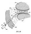
- the present inventionis useful-for helping to create an operating corridor or passage between a percutaneous penetration in the patient's outer skin and a target area within the spine.
- this operating corridoris initially created by inserting one or more dilators through the percutaneous penetration to the target area within the spine, and then introducing a tubular retractor or similar instrument over the largest dilator.
- the hollow interior of the retractor(which will serve as the operating corridor for the introduction of the necessary instruments, such as the endoscope) is typically partially filled with soft tissue, muscle and other body structures.
- the present inventionis particularly useful for precisely and quickly removing these body structures to clear the operating corridor.
- an electrosurgical probe according to the inventionis delivered into the hollow retractor, and one or more electrode terminal(s) are positioned adjacent to or in contact with the soft tissue or other body structures to be removed. High frequency voltage is applied between the electrode terminal(s) and one or more return electrodes such that the tissue is removed.
- the tissuemay be completely ablated in situ with the mechanisms described above, or the tissue may be partially ablated and partially resected and aspirated from this operating corridor.
- the methodfurther comprises aspirating tissue fragments and fluid through an aspiration lumen in the electrosurgical instrument or another instrument.
- the probewill include one or more aspiration electrode(s) at or near the distal opening of the aspiration lumen.
- high frequency voltageis applied between the aspiration electrode(s) and one or more return electrode(s) (which can be the same or different electrodes from the ones used to ablate tissue) to partially or completely ablate the tissue fragments as they are aspirated into the lumen, thus inhibiting clogging of the lumen and expediting the tissue removal process.
- the present inventionoffers a number of advantages over current mechanical and laser techniques for spine surgery.
- the ability to precisely control the volumetric removal of tissueresults in a field of tissue ablation or removal that is very defined, consistent and predictable.
- the shallow depth of tissue heatingalso helps to minimize or completely eliminate damage to healthy tissue structures, cartilage, bone and/or spinal nerves that are often adjacent the target tissue.
- small blood vessels within the tissueare simultaneously cauterized and sealed as the tissue is removed to continuously maintain hemostasis during the procedure. This increases the surgeon's field of view, and shortens the length of the procedure.
- isotonic salinemay be used during the procedure. Saline is the preferred medium for irrigation because it has the same concentration as the body's fluids and, therefore, is not absorbed into the body as much as other fluids.
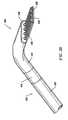
- Apparatusgenerally include an electrosurgical probe or catheter having a shaft with proximal and distal ends, one or more electrode terminal(s) at the distal end and one or more connectors coupling the electrode teriminal(s) to a source of high frequency electrical energy.
- the shaftwill have a distal end portion sized to fit between adjacent vertebrae in the patient's spine.
- the distal end portionis substantially planar, and it offers a low profile, to allow access to confined spaces without risking iatrogenic injury to surrounding body structures or nerves, such as vertebrae or spinal nerves.
- the distal end portionwill have a combined height (i.e., including the active electrode(s)) of less than 2 mm and preferably less than 1 mm.
- the apparatuswill preferably further include a fluid delivery element for delivering electrically conducting fluid to the electrode terminal(s) and the target site.
- the fluid delivery elementmay be located on the probe, e.g., a fluid lumen or tube, or it may be part of a separate instrument.
- an electrically conducting gel or spraysuch as a saline electrolyte or other conductive gel, may be applied the target site.
- the apparatusmay not have a fluid delivery element.
- the electrically conducting fluidwill preferably generate a current flow path between the electrode terminal(s) and one or more return electrode(s).
- the return electrodeis located on the probe and spaced a sufficient distance from the electrode terminal(s) to substantially avoid or minimize current shorting therebetween and to shield the return electrode from tissue at the target site.
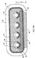
- the electrosurgical probewill include an electrically insulating electrode support member having a tissue treatment surface at the distal end of the probe.
- One or more electrode terminal(s)are coupled to, or integral with, the electrode support member such that the electrode terminal(s) are spaced from the return electrode.
- the probeincludes an electrode array having a plurality of electrically isolated electrode terminals embedded into the electrode support member such that the electrode terminals extend about 0.2 mm to about 10 mm distally from the tissue treatment surface of the electrode support member.
- the probewill further include one or more lumens for delivering electrically conductive fluid to one or more openings around the tissue treatment surface of the electrode support member.
- the lumenwill extend through a fluid tube exterior to the probe shaft that ends proximal to the return electrode.
- the systemmay optionally include a temperature controller coupled to one or more temperature sensors at or near the distal end of the probe.
- the controlleradjusts the output voltage of the power supply in response to a temperature set point and the measured temperature value.
- the temperature sensormay be, for example, a thermocouple, located in the insulating support that measures a temperature at the distal end of the probe.
- the temperature set pointwill preferably be one that corresponds to a tissue temperature that results, for example, in the contraction of the collagen tissue, i.e., about 60°C to 70°C.
- the temperature sensormay directly measure the tissue temperature (e.g., infrared sensor).
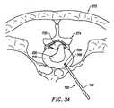
- the present inventionprovides systems for selectively applying electrical energy to a target location within or on a patient's body, particularly including tissue or other body structures in the spine.
- These proceduresinclude laminectomy/disketomy procedures for treating herniated disks, decompressive laminectomy for stenosis in the lumbosacral and cervical spine, medial facetectomy, posterior lumbosacral and cervical spine fusions, treatment of scoliosis associated with vertebral disease, foraminotomies to remove the roof of the intervertebral foramina to relieve nerve root compression and anterior cervical and lumbar diskectomies.
- These proceduresmay be performed through open procedures, or using minimally invasive techniques, such as thoracoscopy, arthroscopy, laparascopy or the like.
- high frequency (RF) electrical energyis applied to one or more electrode terminals in the presence of electrically conductive fluid to remove and/or modify the structure of tissue structures.
- the present inventionmay be used to: (1) volumetrically remove tissue, bone, ligament or cartilage (i.e., ablate or effect molecular dissociation of the body structure); (2) cut or resect tissue or other body structures; (3) shrink or contract collagen connective tissue; and/or (4) coagulate severed blood vessels.
- the RF energyheats the tissue directly by virtue of the electrical current flow therethrough, and/or indirectly through the exposure of the tissue to fluid heated by RF energy, to elevate the tissue temperature from normal body temperatures (e.g., 37°C) to temperatures in the range of 45°C to 90°C, preferably in the range from about 60°C to 70°C.
- Thermal shrinkage of collagen fibersoccurs within a small temperature range which, for mammalian collagen is in the range from 60°C to 70°C ( Deak, G., et al., "The Thermal Shrinkage Process of Collagen Fibres as Revealed by Polarization Optical Analysis of Topooptical Staining Reactions," Acta Morphologica Acad. Sci. of Hungary, Vol. 15(2), pp 195-208, 1967 ).
- Collagen fiberstypically undergo thermal shrinkage in the range of 60°C to about 70°C.
- Previously reported researchhas attributed thermal shrinkage of collagen to the cleaving of the internal stabilizing cross-linkages within the collagen matrix (Deak, ibid).
- the preferred depth of heating to effect the shrinkage of collagen in the heated regioni.e., the depth to which the tissue is elevated to temperatures between 60°C to 70°C
- the depth of heatingis usually in the range from 0 to 3.5 mm. In the case of collagen within the nucleus pulposis, the depth of heating is preferably in the range from about 0 to about 2.0 mm.
- the tissue structuresare volumetrically removed or ablated.
- a high frequency voltage differenceis applied between one or more electrode terminal(s) and one or more return electrode(s) to develop high electric field intensities in the vicinity of the target tissue site.
- the high electric field intensitieslead to electric field induced molecular breakdown of target tissue through molecular dissociation (rather than thermal evaporation or carbonization).
- Applicantbelieves that the tissue structure is volumetrically removed through molecular disintegration of larger organic molecules into smaller molecules and/or atoms, such as hydrogen, oxides of carbon, hydrocarbons and nitrogen compounds. This molecular disintegration completely removes the tissue structure, as opposed to dehydrating the tissue material by the removal of liquid within the cells of the tissue, as is typically the case with electrosurgical desiccation and vaporization.
- the high electric field intensitiesmay be generated by applying a high frequency voltage that is sufficient to vaporize an electrically conducting fluid over at least a portion of the electrode terminal(s) in the region between the distal tip of the electrode terminal(s) and the target tissue.
- the electrically conductive fluidmay be a gas or liquid, such as isotonic saline, delivered to the target site, or a viscous fluid, such as a gel, that is located at the target site. In the latter embodiment, the electrode terminal(s) are submersed in the electrically conductive gel during the surgical procedure.
- the vapor layer or vaporized regionSince the vapor layer or vaporized region has a relatively high electrical impedance, it increases the voltage differential between the electrode terminal tip and the tissue and causes ionization within the vapor layer due to the presence of an ionizable species (e.g., sodium when isotonic saline is the electrically conducting fluid). This ionization, under optimal conditions, induces the discharge of energetic electrons and photons from the vapor layer and to the surface of the target tissue. This energy may be in the form of energetic photons (e.g., ultraviolet radiation), energetic particles (e.g., electrons) or a combination thereof.
- Coblation TMA more detailed description of this cold ablation phenomena, termed Coblation TM , can be found in commonly assigned U.S. Patent No. 5,697,882 .
- the present inventionapplies high frequency (RF) electrical energy in an electrically conducting fluid environment to remove (i.e., resect, cut or ablate) or contract a tissue structure, and to seal transected vessels within the region of the target tissue.
- RFhigh frequency
- the present inventionis particularly useful for sealing larger arterial vessels, e.g., on the order of 1 mm or greater.
- a high frequency power supplyis provided having an ablation mode, wherein a first voltage is applied to an electrode terminal sufficient to effect molecular dissociation or disintegration of the tissue, and a coagulation mode, wherein a second, lower voltage is applied to an electrode terminal (either the same or a different electrode) sufficient to achieve hemostasis of severed vessels within the tissue.
- an electrosurgical probehaving one or more coagulation electrode(s) configured for sealing a severed vessel, such as an arterial vessel, and one or more electrode terminals configured for either contracting the collagen fibers within the tissue or removing (ablating) the tissue, e.g., by applying sufficient energy to the tissue to effect molecular dissociation.
- the coagulation electrode(s)may be configured such that a single voltage can be applied to coagulate with the coagulation electrode(s), and to ablate or contract with the electrode terminal(s).
- the power supplyis combined with the coagulation probe such that the coagulation electrode is used when the power supply is in the coagulation mode (low voltage), and the electrode terminal(s) are used when the power supply is in the ablation mode (higher voltage).
- one or more electrode terminalsare brought into close proximity to tissue at a target site, and the power supply is activated in the ablation mode such that sufficient voltage is applied between the electrode terminals and the return electrode to volumetrically remove the tissue through molecular dissociation, as described below.
- the power supplyis activated in the ablation mode such that sufficient voltage is applied between the electrode terminals and the return electrode to volumetrically remove the tissue through molecular dissociation, as described below.
- vessels within the tissuewill be severed. Smaller vessels will be automatically sealed with the system and method of the present invention. Larger vessels, and those with a higher flow rate, such as arterial vessels, may not be automatically sealed in the ablation mode. In these cases, the severed vessels may be sealed by activating a control (e.g., a foot pedal) to reduce the voltage of the power supply into the coagulation mode.
- a controle.g., a foot pedal
- the electrode terminalsmay be pressed against the severed vessel to provide sealing and/or coagulation of the vessel.
- a coagulation electrode located on the same or a different probemay be pressed against the severed vessel.
- the present inventionis particularly useful for removing or ablating tissue around nerves, such as spinal or cranial nerves, e.g., the spinal cord and the surrounding dura mater.
- nervessuch as spinal or cranial nerves, e.g., the spinal cord and the surrounding dura mater.
- One of the significant drawbacks with the prior art cutters, graspers, and lasersis that these devices do not differentiate between the target tissue and the surrounding nerves or bone. Therefore, the surgeon must be extremely careful during these procedures to avoid damage to the bone or nerves within and around the spinal cord.
- the Coblation TM process for removing tissueresults in extremely small depths of collateral tissue damage as discussed above. This allows the surgeon to remove tissue close to a nerve without causing collateral damage to the nerve fibers.
- Nervesusually comprise a connective tissue sheath, or endoneurium, enclosing the bundles of nerve fibers to protect these nerve fibers.
- This protective tissue sheathtypically comprises a fatty tissue (e.g., adipose tissue) having substantially different electrical properties than the normal target tissue, such as the disc and other surrounding tissue that are, for example, removed from the spine during spinal procedures.
- the system of the present inventionmeasures the electrical properties of the tissue at the tip of the probe with one or more electrode terminal(s). These electrical properties may include electrical conductivity at one, several or a range of frequencies (e.g., in the range from 1 kHz to 100 MHz), dielectric constant, capacitance or combinations of these.
- an audible signalmay be produced when the sensing electrode(s) at the tip of the probe detects the fatty tissue surrounding a nerve, or direct feedback control can be provided to only supply power to the electrode terminal(s) either individually or to the complete array of electrodes, if and when the tissue encountered at the tip or working end of the probe is normal tissue based on the measured electrical properties.
- the current limiting elementsare configured such that the electrode terminals will shut down or turn off when the electrical impedance reaches a threshold level.
- a threshold levelis set to the impedance of the fatty tissue surrounding nerves, the electrode terminals will shut off whenever they come in contact with, or in close proximity to, nerves. Meanwhile, the other electrode terminals, which are in contact with or in close proximity to nasal tissue, will continue to conduct electric current to the return electrode.
- the Coblation TM mechanism of the present inventioncan be manipulated to ablate or remove certain tissue structures, while having little effect on other tissue structures.
- the present inventionuses a technique of vaporizing electrically conductive fluid to form a plasma layer or pocket around the electrode terminal(s), and then inducing the discharge of energy from this plasma or vapor layer to break the molecular bonds of the tissue structure. Based on initial experiments, applicants believe that the free electrons within the ionized vapor layer are accelerated in the high electric fields near the electrode tip(s).
- the electron mean free pathincreases to enable subsequently injected electrons to cause impact ionization within these regions of low density (i.e., vapor layers or bubbles).
- Energy evolved by the energetic electronse.g., 4 to 5 eV
- the energy evolved by the energetic electronsmay be varied by adjusting a variety of factors, such as: the number of electrode terminals; electrode size and spacing; electrode surface area; asperities and sharp edges on the electrode surfaces; electrode materials; applied voltage and power; current limiting means, such as inductors; electrical conductivity of the fluid in contact with the electrodes; density of the fluid; and other factors. Accordingly, these factors can be manipulated to control the energy level of the excited electrons. Since different tissue structures have different molecular bonds, the present invention can be configured to break the molecular bonds of certain tissue, while having too low an energy to break the molecular bonds of other tissue.
- fatty tissuee.g., adipose
- fatty tissuee.g., adipose
- the present invention in its current configurationgenerally does not ablate or remove such fatty tissue.
- factorsmay be changed such that these double bonds can be broken (e.g., increasing voltage or changing the electrode configuration to increase the current density at the electrode tips).
- the electrosurgical probe or catheterwill comprise a shaft or a handpiece having a proximal end and a distal end which supports one or more electrode ternninal(s).
- the shaft or handpiecemay assume a wide variety of configurations, with the primary purpose being to mechanically support the active electrode and permit the treating physician to manipulate the electrode from a proximal end of the shaft.
- the shaftmay be rigid or flexible, with flexible shafts optionally being combined with a generally rigid external tube for mechanical support. Flexible shafts may be combined with pull wires, shape memory actuators, and other known mechanisms for effecting selective deflection of the distal end of the shaft to facilitate positioning of the electrode array.
- the shaftwill usually include a plurality of wires or other conductive elements running axially therethrough to permit connection of the electrode array to a connector at the proximal end of the shaft.
- the shaftwill have a suitable diameter and length to allow the surgeon to reach the target site (e.g., a disc) by delivering the shaft through the thoracic cavity, the abdomen or the like.
- the shaftwill usually have a length in the range of about 5.0 to 30.0 cm, and a diameter in the range of about 0.2 mm to about 20 mm.
- the shaftmay be delivered directly through the patient's back in a posterior approach, which would considerably reduce the required length of the shaft.
- the shaftmay also be introduced through rigid or flexible endoscopes. Specific shaft designs will be described in detail in connection with the figures hereinafter.
- the probemay comprise a long, thin needle (e.g., on the order of about 1 mm in diameter or less) that can be percutaneously introduced through the patient's back directly into the spine (see Figs. 34-36).
- the needlewill include one or more active electrode(s) for applying electrical energy to tissues within the spine.
- the needlemay include one or more return electrode(s), or the return electrode may be positioned on the patient's back, as a dispersive pad. In either embodiment, sufficient electrical energy is applied through the needle to the active electrode(s) to either shrink the collagen fibers within the spinal disk, or to ablate tissue within the disk.
- the current flow path between the electrode terminal(s) and the return electrode(s)may be generated by submerging the tissue site in an electrical conducting fluid (e.g., within a liquid or a viscous fluid, such as an electrically conductive gel) or by directing an electrically conducting fluid along a fluid path to the target site (i.e., a liquid, such as isotonic saline, or a gas, such as argon).
- an electrical conducting fluide.g., within a liquid or a viscous fluid, such as an electrically conductive gel
- directing an electrically conducting fluid along a fluid path to the target sitei.e., a liquid, such as isotonic saline, or a gas, such as argon.
- the system of the present inventionwill usually include a suction lumen in the probe, or on another instrument, for aspirating fluids from the target site.
- the inventionmay include one or more aspiration electrode(s) coupled to the distal end of the suction lumen for ablating, or at least reducing the volume of, non-ablated tissue fragments that are aspirated into the lumen.
- the aspiration electrode(s)function mainly to inhibit clogging of the lumen that may otherwise occur as larger tissue fragments are drawn therein.
- the aspiration electrode(s)may be different from the ablation electrode terminal(s), or the same electrode(s) may serve both functions. - A more complete description of probes incorporating aspiration electrode(s) can be found in commonly assigned, co-pending U.S. Patent Application No. 09/010,382, filed January 21, 1998 .
- the present inventionmay use a single active electrode terminal or an electrode array distributed over a contact surface of a probe.
- the electrode arrayusually includes a plurality of independently current-limited and/or power-controlled electrode terminals to apply electrical energy selectively to the target tissue while limiting the unwanted application of electrical energy to the surrounding tissue and environment resulting from power dissipation into surrounding electrically conductive liquids, such as blood, normal saline, electrically conductive gel and the like.
- the electrode terminalsmay be independently current-limited by isolating the terminals from each other and connecting each terminal to a separate power source that is isolated from the other electrode terminals.
- the electrode terminalsmay be connected to each other at either the proximal or distal ends of the probe to form a single wire that couples to a power source.
- the active electrode(s)have an active portion or surface with surface geometries shaped to promote the electric field intensity and associated current density along the leading edges of the electrodes. Suitable surface geometries may be obtained by creating electrode shapes that include preferential sharp edges, or by creating asperities or other surface roughness on the active surface(s) of the electrodes. Electrode shapes according to the present invention can include the use of formed wire (e.g., by drawing round wire through a shaping die) to form electrodes with a variety of cross-sectional shapes, such as square, rectangular, L or V shaped, or the like. Electrode edges may also be created by removing a portion of the elongate metal electrode to reshape the cross-section.
- materialcan be ground along the length of a round or hollow wire electrode to form D or C shaped wires, respectively, with edges facing in the cutting direction.
- materialcan be removed at closely spaced intervals along the electrode length to form transverse grooves, slots, threads or the like along the electrodes.
- the active electrode surface(s)may be modified through chemical, electrochemical or abrasive methods to create a multiplicity of surface asperities on the electrode surface. These surface asperities will promote high electric field intensities between the active electrode surface(s) and the target tissue to facilitate ablation or cutting of the tissue.
- surface asperitiesmay be created by etching the active electrodes with etchants having a Ph less than 7.0 or by using a high velocity stream of abrasive particles (e.g., grit blasting) to create asperities on the surface of an elongated electrode.
- the active electrode(s)are typically mounted in an electrically insulating electrode support that extends from the electrosurgical probe.
- the electrode supportcomprises a plurality of wafer layers bonded together, e.g., by a glass adhesive or the like, or a single wafer.
- the wafer layer(s)have conductive strips printed thereon to form the electrode terminal(s) and the return electrode(s).
- the proximal end of the wafer layer(s)will have a number of holes extending from the conductor strips to an exposed surface of the wafer layers for connection to electrical conductor lead traces in the electrosurgical probe or handpiece.
- the wafer layerspreferably comprise a ceramic material , such as alumina, and the electrode will preferably comprise a metallic material, such as gold, copper, platinum, palladium, tungsten, silver or the like.
- a ceramic materialsuch as alumina
- the electrodewill preferably comprise a metallic material, such as gold, copper, platinum, palladium, tungsten, silver or the like.
- Suitable multilayer ceramic electrodesare commercially available from e.g., VisPro Corporation of Beaverton, Oregon.
- each individual electrode terminal in the electrode arrayis electrically insulated from all other electrode terminals in the array within said probe and is connected to a power source which is isolated from each of the other electrode terminals in the array or to circuitry which limits or interrupts current flow to the electrode terminal when low resistivity material (e.g., blood, electrically conductive saline irrigant or electrically conductive gel) causes a lower impedance path between the return electrode and the individual electrode terminal.
- the isolated power sources for each individual electrode terminalmay be separate power supply circuits having internal impedance characteristics which limit power to the associated electrode terminal when a low impedance return path is encountered.
- the isolated power sourcemay be a user selectable constant current source.
- a single power sourcemay be connected to each of the electrode terminals through independently actuatable switches, or by independent current limiting elements, such as inductors, capacitors, resistors and/or combinations thereof.
- the current limiting elementsmay be provided in the probe, connectors, cable, controller or along the conductive path from the controller to the distal tip of the probe.
- the resistance and/or capacitancemay occur on the surface of the active electrode terminal(s) due to oxide layers which form selected electrode terminals (e.g., titanium or a resistive coating on the surface of metal, such as platinum).
- the tip region of the probemay comprise many independent electrode terminals designed to deliver electrical energy in the vicinity of the tip.
- the selective application of electrical energy to the conductive fluidis achieved by connecting each individual electrode terminal and the return electrode to a power source having independently controlled or current limited channels.
- the return electrode(s)may comprise a single tubular member of conductive material proximal to the electrode array at the tip which also serves as a conduit for the supply of the electrically conducting fluid between the active and return electrodes.
- the probemay comprise an array of return electrodes at the distal tip of the probe (together with the active electrodes) to maintain the electric current at the tip.
- the application of high frequency voltage between the return electrode(s) and the electrode arrayresults in the generation of high electric field intensities at the distal tips of the electrode terminals with conduction of high frequency current from each individual electrode terminal to the return electrode.
- the current flow from each individual electrode terminal to the return electrode(s)is controlled by either active or passive means, or a combination thereof, to deliver electrical energy to the surrounding conductive fluid while minimizing energy delivery to surrounding (non-target) tissue.
- the application of a high frequency voltage between the return electrode(s) and the electrode terminal(s) for appropriate time intervalseffects cutting, removing, ablating, shaping, contracting or otherwise modifying the target tissue.
- the tissue volume over which energy is dissipatedi.e., a high current density exists
- the tissue volume over which energy is dissipatedmay be precisely controlled, for example, by the use of a multiplicity of small electrode terminals whose effective diameters or principal dimensions range from about 5 mm to 0.01 mm, preferably from about 2 mm to 0.05 mm, and more preferably from about 1 mm to 0.1 mm.
- Electrode areas for both circular and non-circular terminalswill have a contact area (per electrode terminal) below 25 mm 2 , preferably being in the range from 0.0001 mm 2 to 1 mm 2 , and more preferably from 0.005 mm 2 to .5 mm 2 .
- the circumscribed area of the electrode arrayis in the range from 0.25 mm 2 to 200 mm 2 , preferably from 0.5 mm 2 to 100 mm 2 , and will usually include at least two isolated electrode terminals, preferably at least five electrode terminals, often greater than 10 electrode terminals and even 50 or more electrode terminals, disposed over the distal contact surfaces on the shaft.
- the use of small diameter electrode terminalsincreases the electric field intensity and reduces the extent or depth of tissue heating as a consequence of the divergence of current flux lines which emanate from the exposed surface of each electrode terminal.
- the area of the tissue treatment surfacecan vary widely, and the tissue treatment surface can assume a variety of geometries, with particular areas and geometries being selected for specific applications.
- Active electrode surfacescan have areas in the range from 0.25 mm 2 to 75 mm 2 , usually being from about 0.5 mm 2 to 40 mm 2 .
- the geometriescan be planar, concave, convex, hemispherical, conical, linear "in-line” array or virtually any other regular or irregular shape.
- the active electrode(s) or electrode terminal(s)will be formed at the distal tip of the electrosurgical probe shaft, frequently being planar, disk-shaped, or hemispherical surfaces for use in reshaping procedures or being linear arrays for use in cutting.
- the active electrode(s)may be formed on lateral surfaces of the electrosurgical probe shaft (e.g., in the manner of a spatula), facilitating access to certain body structures in endoscopic procedures.
- the electrically conducting fluidshould have a threshold conductivity to provide a suitable conductive path between the return electrode(s) and the electrode terminal(s).
- the electrical conductivity of the fluid(in units of milliSiemans per centimeter or mS/cm) will usually be greater than 0.2 mS/cm, preferably will be greater than 2 mS/cm and more preferably greater than 10 mS/cm.
- the electrically conductive fluidis isotonic saline, which has a conductivity of about 17 mS/cm.
- the fluidmay be an electrically conductive gel or spray, such as a saline electrolyte gel, a conductive ECG spray, an electrode conductivity gel, an ultrasound transmission or scanning gel, or the like.
- Suitable gels or spraysare commercially available from Graham-Field, Inc of Hauppauge, New York.
- the electrode support and the fluid outletmay be recessed from an outer surface of the probe or handpiece to confine the electrically conductive fluid to the region immediately surrounding the electrode support.
- the shaftmay be shaped so as to form a cavity around the electrode support and the fluid outlet. This helps to assure that the electrically conductive fluid will remain in contact with the electrode terminal(s) and the return electrode(s) to maintain the conductive path therebetween. In addition, this will help to maintain a vapor or plasma layer between the electrode terminal(s) and the tissue at the treatment site throughout the procedure, which reduces the thermal damage that might otherwise occur if the vapor layer were extinguished due to a lack of conductive fluid. Provision of the electrically conductive fluid around the target site also helps to maintain the tissue temperature at desired levels.
- the voltage applied between the return electrode(s) and the electrode arraywill be at high or radio frequency, typically between about 5 kHz and 20 MHz, usually being between about 30 kHz and 2.5 MHz, preferably being between about 50 kHz and 500 kHz, often less than 350 kHz, and often between about 100 kHz and 200 kHz.
- the RMS (root mean square) voltage appliedwill usually be in the range from about 5 volts to 1000 volts, preferably being in the range from about 10 volts to 500 volts depending on the electrode terminal size, the operating frequency and the operation mode of the particular procedure or desired effect on the tissue (i.e., contraction, coagulation or ablation).
- the peak-to-peak voltagewill be in the range of 10 to 2000 volts, preferably in the range of 20 to 1200 volts and more preferably in the range of about 40 to 800 volts (again, depending on the electrode size, the operating frequency and the operation mode).
- the voltageis usually delivered in a series of voltage pulses or alternating current of time varying voltage amplitude with a sufficiently high frequency (e.g., on the order of 5 kHz to 20 MHz) such that the voltage is effectively applied continuously (as compared with e.g., lasers claiming small depths of necrosis, which are generally pulsed about 10 to 20 Hz).
- the duty cyclei.e., cumulative time in any one-second interval that energy is applied
- the preferred power source of the present inventiondelivers a high frequency current selectable to generate average power levels ranging from several milliwatts to tens of watts per electrode, depending on the volume of target tissue being heated, and/or the maximum allowed temperature selected for the probe tip.
- the power sourceallows the user to select the voltage level according to the specific requirements of a particular spine procedure, arthroscopic surgery, dermatological procedure, ophthalmic procedures, FESS procedure, open surgery or other endoscopic surgery procedure.
- a description of a suitable power sourcecan be found in U.S. Provisional Patent Application No. 60/062,997 filed October 23, 1997 (Attorney Docket No. 16238-007400).
- the power sourcemay be current limited or otherwise controlled so that undesired heating of the target tissue or surrounding (non-target) tissue does not occur.
- current limiting inductorsare placed in series with each independent electrode terminal, where the inductance of the inductor is in the range of 10uH to 50,OOOuH, depending on the electrical properties of the target tissue, the desired tissue heating rate and the operating frequency.
- capacitor-inductor (LC) circuit structuresmay be employed.
- current limiting resistorsmay be selected.
- these resistorswill have a large positive temperature coefficient of resistance so that, as the current level begins to rise for any individual electrode terminal in contact with a low resistance medium (e.g., saline irrigant or conductive gel), the resistance of the current limiting resistor increases significantly, thereby minimizing the power delivery from said electrode terminal into the low resistance medium (e. g. , saline irrigant or conductive gel).
- a low resistance mediume.g., saline irrigant or conductive gel
- the inventionis not limited to electrically isolated electrode terminals, or even to a plurality of electrode terminals.
- the array of active electrode terminalsmay be connected to a single lead that extends through the probe shaft to a power source of high frequency current.
- the probemay incorporate a single electrode that extends directly through the probe shaft or is connected to a single lead that extends to the power source.
- the active electrodemay have a ball shape (e.g., for tissue vaporization and desiccation), a twizzle shape (for vaporization and needle-like cutting), a spring shape (for rapid tissue debulking and desiccation), a twisted metal shape, an annular or solid tube shape or the like.
- the electrodemay comprise a plurality of filaments, a rigid or flexible brush electrode (for debulking a tumor, such as a fibroid, bladder tumor or a prostate adenoma), a side-effect brush electrode on a lateral surface of the shaft, a coiled electrode or the like.
- the probecomprises a single active electrode terminal that extends from an insulating member, e.g., ceramic, at the distal end of the probe.
- the insulating memberis preferably a tubular structure that separates the active electrode terminal from a tubular or annular return electrode positioned proximal to the insulating member and the active electrode.
- Electrosurgical system 11generally comprises an electrosurgical handpiece or probe 10 connected to a power supply 28 for providing high frequency voltage to a target site and a fluid source 21 for supplying electrically conducting fluid 50 to probe 10.
- electrosurgical system 11may include an endoscope (not shown) with a fiber optic head light for viewing the surgical site, particularly in endoscopic spine procedures.
- the endoscopemay be integral with probe 10, or it may be part of a separate instrument.
- the system 11may also include a vacuum source (not shown) for coupling to a suction lumen or tube 211 (see Fig. 2) in the probe 10 for aspirating the target site.
- probe 10generally includes a proximal handle 19 and an elongate shaft 18 having an array 12 of electrode terminals 58 at its distal end.
- a connecting cable 34has a connector 26 for electrically coupling the electrode terminals 58 to power supply 28.
- the electrode terminals 58are electrically isolated from each other and each of the terminals 58 is connected to an active or passive control network within power supply 28 by means of a plurality of individually insulated conductors (not shown).
- a fluid supply tube 15is connected to a fluid tube 14 of probe 10 for supplying electrically conducting fluid 50 to the target site.
- Power supply 28has an operator controllable voltage level adjustment 30 to change the applied voltage level, which is observable at a voltage level display 32.
- Power supply 28also includes first, second and third foot pedals 37, 38, 39 and a cable 36 which is removably coupled to power supply 28.
- the foot pedals 37, 38, 39allow the surgeon to remotely adjust the energy level applied to electrode terminals 58.
- first foot pedal 37is used to place the power supply into the "ablation” mode and second foot pedal 38 places power supply 28 into the "coagulation” mode.
- the third foot pedal 39allows the user to adjust the voltage level within the "ablation” mode.
- a sufficient voltageis applied to the electrode terminals to establish the requisite conditions for molecular dissociation of the tissue (i.e., vaporizing a portion of the electrically conductive fluid, ionizing charged particles within the vapor layer and accelerating these charged particles against the tissue).
- the requisite voltage level for ablationwill vary depending on the number, size, shape and spacing of the electrodes, the distance in which the electrodes extend from the support member, etc.
- the power supply 28applies a low enough voltage to the electrode terminals (or the coagulation electrode) to avoid vaporization of the electrically conductive fluid and subsequent molecular dissociation of the tissue.
- the surgeonmay automatically toggle the power supply between the ablation and coagulation modes by alternatively stepping on foot pedals 37, 38, respectively. This allows the surgeon to quickly move between coagulation and ablation in situ, without having to remove his/her concentration from the surgical field or without having to request an assistant to switch the power supply.
- the probetypically will simultaneously seal and/or coagulation small severed vessels within the tissue.
- the surgeoncan simply step on foot pedal 38, automatically lowering the voltage level below the threshold level for ablation, and apply sufficient pressure onto the severed vessel for a sufficient period of time to seal and/or coagulate the vessel. After this is completed, the surgeon may quickly move back into the ablation mode by stepping on foot pedal 37.
- Figs. 2-5illustrate an exemplary electrosurgical probe 20 constructed according to the principles of the present invention.
- probe 20generally includes an elongated shaft 100 which may be flexible or rigid, a handle 204 coupled to the proximal end of shaft 100 and an electrode support member 102 coupled to the distal end of shaft 100.
- Shaft 100preferably comprises a plastic material that is easily molded into the shape shown in Fig. 2.
- shaft 100comprises an electrically conducting material, usually metal, which is selected from the group comprising tungsten, stainless steel alloys, platinum or its alloys, titanium or its alloys, molybdenum or its alloys, and nickel or its alloys.
- shaft 100includes an electrically insulating jacket 108, which is typically formed as one or more electrically insulating sheaths or coatings, such as polytetrafluoroethylene, polyimide, and the like.
- electrically insulating jacket 108is typically formed as one or more electrically insulating sheaths or coatings, such as polytetrafluoroethylene, polyimide, and the like.
- the provision of the electrically insulating jacket over the shaftprevents direct electrical contact between these metal elements and any adjacent body structure or the surgeon. Such direct electrical contact between a body structure (e.g., tendon) and an exposed electrode could result in unwanted heating and necrosis of the structure at the point of contact causing necrosis.
- Handle 204typically comprises a plastic material that is easily molded into a suitable shape for handling by the surgeon. Handle 204 defines an inner cavity (not shown) that houses the electrical connections 250 (Fig. 5), and provides a suitable interface for connection to an electrical connecting cable 22 (see Fig. 1). Electrode support member 102 extends from the distal end of shaft 100 (usually about 1 to 20 mm), and provides support for a plurality of electrically isolated electrode terminals 104 (see Fig. 4). As shown in Fig. 2, a fluid tube 233 extends through an opening in handle 204, and includes a connector 235 for connection to a fluid supply source, for supplying electrically conductive fluid to the target site.
- Fluid tube 233is coupled to a distal fluid tube 239 that extends along the outer surface of shaft 100 to an opening 237 at the distal end of the probe 20, as discussed in detail below.
- fluid tube 233may extend through a single lumen (not shown) in shaft 100, or it may be coupled to a plurality of lumens (also not shown) that extend through shaft 100 to a plurality of openings at its distal end.
- Probe 20may also include a valve 17 (Fig. 1) or equivalent structure for controlling the flow rate of the electrically conducting fluid to the target site.
- electrode support member 102has a substantially planar tissue treatment surface 212 and comprises a suitable insulating material (e.g., ceramic or glass material, such as alumina, zirconia and the like) which could be formed at the time of manufacture in a flat, hemispherical or other shape according to the requirements of a particular procedure.
- a suitable insulating materiale.g., ceramic or glass material, such as alumina, zirconia and the like
- the preferred support member materialis alumina, available from Kyocera Industrial Ceramics Corporation, Elkgrove, Illinois, because of its high thermal conductivity, good electrically insulative properties, high flexural modulus, resistance to carbon tracking, biocompatibility, and high melting point.
- the support member 102is adhesively joined to a tubular support member (not shown) that extends most or all of the distance between support member 102 and the proximal end of probe 20.
- the tubular memberpreferably comprises an electrically insulating material, such as an epoxy or silicone-based material.
- electrode terminals 104extend through pre-formed openings in the support member 102 so that they protrude above tissue treatment surface 212 by the desired distance.
- the electrodesare then bonded to the tissue treatment surface 212 of support member 102, typically by an inorganic sealing material.
- the sealing materialis selected to provide effective electrical insulation, and good adhesion to both the alumina member 102 and the platinum or titanium electrode terminals 104.
- the sealing materialadditionally should have a compatible thermal expansion coefficient and a melting point well below that of platinum or titanium and alumina or zirconia, typically being a glass or glass ceramic
- probe 20includes a return electrode 112 for completing the current path between electrode terminals 104 and a high frequency power supply 28 (see Fig. 1).
- return electrode 112preferably comprises an annular conductive band coupled to the distal end of shaft 100 slightly proximal to tissue treatment surface 212 of electrode support member 102, typically about 0.5 to 10 mm and more preferably about 1 to 10 mm.
- Return electrode 112is coupled to a connector 258 that extends to the proximal end of probe 10, where it is suitably connected to power supply 10 (Fig. 1).
- return electrode 112is not directly connected to electrode terminals 104.
- electrically conducting fluide.g., isotonic saline
- the electrically conducting fluidis delivered through an external fluid tube 239 to opening 237, as described above.
- the fluidmay be delivered by a fluid delivery element (not shown) that is separate from probe 20.
- the trocar cannulamay be flooded with isotonic saline and the probe 20 will be introduced into this flooded cavity. Electrically conducting fluid will be continually resupplied with a separate instrument to maintain the conduction path between return electrode 112 and electrode terminals 104.
- the fluid pathmay be formed in probe 20 by, for example, an inner lumen or an annular gap between the return electrode and a tubular support member within shaft 100 (not shown).
- This annular gapmay be formed near the perimeter of the shaft 100 such that the electrically conducting fluid tends to flow radially inward towards the target site, or it may be formed towards the center of shaft 100 so that the fluid flows radially outward.
- a fluid sourcee.g., a bag of fluid elevated above the surgical site or having a pumping device
- a fluid supply tube(not shown) that may or may not have a controllable valve.
- the electrically isolated electrode terminals 104are spaced apart over tissue treatment surface 212 of electrode support member 102.
- the tissue treatment surface and individual electrode terminals 104will usually have dimensions within the ranges set forth above.
- the tissue treatment surface 212has a circular cross-sectional shape with a diameter in the range of about 1 mm to 30 mm, usually about 2 to 20 mm.
- the individual electrode terminals 104preferably extend outward from tissue treatment surface 212 by a distance of about 0.1 to 8 mm, usually about 0.2 to 4 mm. Applicant has found that this configuration increases the high electric field intensities and associated current densities around electrode terminals 104 to facilitate the ablation of tissue as described in detail above.
- the probeincludes a single, larger opening 209 in the center of tissue treatment surface 212, and a plurality of electrode terminals (e.g., about 3-15) around the perimeter of surface 212 (see Fig. 3).
- the probemay include a single, annular, or partially annular, electrode terminal at the perimeter of the tissue treatment surface.
- the central opening 209is coupled to a suction or aspiration lumen 213 (see Fig. 2) within shaft 100 and a suction tube 211 (Fig. 2) for aspirating tissue, fluids and/or gases from the target site.
- the electrically conductive fluidgenerally flows from opening 237 of fluid tube 239 radially inward past electrode terminals 104 and then back through the central opening 209 of support member 102.
- Aspirating the electrically conductive fluid during surgeryallows the surgeon to see the target site, and it prevents the fluid from flowing into the patient's body, e.g., into the spine, the abdomen or the thoracic cavity. This aspiration should be controlled, however, so that the conductive fluid maintains a conductive path between the active electrode terminal(s) and the return electrode.
- the distal tip of probemay have a variety of different configurations.
- the probemay include a plurality of openings 209 around the outer perimeter of tissue treatment surface 212 (this embodiment not shown in the drawings).
- the electrode terminals 104extend from the center of tissue treatment surface 212 radially inward from openings 209.
- the openingsare suitably coupled to fluid tube 233 for delivering electrically conductive fluid to the target site, and aspiration lumen 213 for aspirating the fluid after it has completed the conductive path between the return electrode 112 and the electrode terminals 104.
- the probe 20will also include one or more aspiration electrode(s) coupled to the aspiration lumen for inhibiting clogging during aspiration of tissue fragments from the surgical site.
- one or more of the active electrode terminals 104may comprise loop electrodes 140 that extend across distal opening 209 of the suction lumen within shaft 100.
- two of the electrode terminals 104comprise loop electrodes 140 that cross over the distal opening 209.
- the electrodesmay have shapes other than loops, such as the coiled configurations shown in Figs. 6 and 7.
- the electrodesmay be formed within suction lumen proximal to the distal opening 209, as shown in Fig. 8.
- the main function of loop electrodes 140is to ablate portions of tissue that are drawn into the suction lumen to prevent clogging of the lumen.
- Loop electrodes 140are electrically isolated from the other electrode terminals 104, which can be referred to hereinafter as the ablation electrodes 104. Loop electrodes 140 may or may not be electrically isolated from each other. Loop electrodes 140 will usually extend only about 0.05 to 4 mm, preferably about 0.1 to 1 mm from the tissue treatment surface of electrode support member 104.
- the aspiration electrodesmay comprise a pair of coiled electrodes 150 that extend across distal opening 209 of the suction lumen.
- the larger surface area of the coiled electrodes 150usually increases the effectiveness of the electrodes 150 on tissue fragments passing through opening 209.
- the aspiration electrodecomprises a single coiled electrode 152 passing across the distal opening 209 of suction lumen. This single electrode 152 may be sufficient to inhibit clogging of the suction lumen.
- the aspiration electrodesmay be positioned within the suction lumen proximal to the distal opening 209. Preferably, these electrodes are close to opening 209 so that tissue does not clog the opening 209 before it reaches electrodes 154.
- a separate return electrode 156may be provided within the suction lumen to confine the electric currents therein.
- another embodiment of the present inventionincorporates an aspiration electrode 160 within the aspiration lumen 162 of the probe.
- the electrode 160is positioned just proximal of distal opening 209 so that the tissue fragments are ablated as they enter lumen 162.
- the aspiration electrode 160comprises a loop electrode that stretches across the aspiration lumen 162.
- the return electrode 164is located outside of the probe as in the previously embodiments.
- the return electrode(s)may be located within the aspiration lumen 162 with the aspiration electrode 160.
- the inner insulating coating 163may be exposed at portions within the lumen 162 to provide a conductive path between this exposed portion of return electrode 164 and the aspiration electrode 160.
- the latter embodimenthas the advantage of confining the electric currents to within the aspiration lumen.
- itis usually easier to maintain a conductive fluid path between the active and return electrodes in the latter embodiment because the conductive fluid is aspirated through the aspiration lumen 162 along with the tissue fragments.
- mesh electrode 600extending across the distal portion of aspiration lumen 162.
- mesh electrode 600includes a plurality of openings 602 to allow fluids and tissue fragments to flow through into aspiration lumen 162.
- the size of the openings 602will vary depending on a variety of factors.
- the mesh electrodemay be coupled to the distal or proximal surfaces of ceramic support member 102.
- Wire mesh electrode 600comprises a conductive material, such as titanium, tantalum, steel, stainless steel, tungsten, copper, gold or the like.
- wire mesh electrode 600comprises a different material having a different electric potential than the active electrode terminal(s) 104.
- mesh electrode 600comprises steel and electrode terminal(s) comprises tungsten. Applicant has found that a slight variance in the electrochemical potential of mesh electrode 600 and electrode terminal(s) 104 improves the performance of the device. Of course, it will be recognized that the mesh electrode may be electrically insulated from active electrode terminal(s) as in previous embodiments
- metal screen 610has a plurality of peripheral openings 612 for receiving electrode terminals 104, and a plurality of inner openings 614 for allowing aspiration of fluid and tissue through opening 609 of the aspiration lumen. As shown, screen 610 is press fitted over electrode terminals 104 and then adhered to shaft 100 of probe 20. Similar to the mesh electrode embodiment, metal screen 610 may comprise a variety of conductive metals, such as titanium, tantalum, steel, stainless steel, tungsten, copper, gold or the like. In the representative embodiment, metal screen 610 is coupled directly to, or integral with, active electrode terminal(s) 104. In this embodiment, the active electrode terminal(s) 104 and the metal screen 610 are electrically coupled to each other.
- Figs. 32 and 33illustrate alternative embodiments of the mesh and screen aspiration electrodes.
- the probemay include a conductive cage electrode 620 that extends into the aspiration lumen 162 (not shown) to increase the effect of the electrode on aspirated tissue.
- Figs. 33A-33Cillustrate a dome-shaped screen electrode 630 that includes one or more anchors 632 (four in the representative embodiment) for attaching the screen electrode 630 to a conductive spacer 634.
- Screen electrode 630includes a plurality of holes 631 for allowing fluid and tissue fragments to pass therethrough to aspiration lumen 162.
- Screen electrode 630is sized to fit within opening 609 of aspiration lumen 162 except for the anchors 632 which include holes 633 for receiving electrode terminals 104.
- Spacer 634includes peripheral holes 636 for receiving electrode terminals 104 and a central hole 638 aligned with suction lumen 162.
- Spacer 634may further include insulated holes 640 for electrically isolating screen electrode 630 from electrode terminals 104.
- dome-shaped screen electrode 630preferably extends distally from the probe shaft 100 about the same distance as the electrode terminals 104. Applicant has found that this configuration enhances the ablation rate for tissue adjacent to electrode terminals 104, while still maintaining the ability to ablate aspirated tissue fragments passing through screen 630.
- Fig. 5illustrates the electrical connections 250 within handle 204 for coupling electrode terminals 104 and return electrode 112 to the power supply 28.
- a plurality of wires 252extend through shaft 100 to couple terminals 104 to a plurality of pins 254, which are plugged into a connector block 256 for coupling to a connecting cable 22 (Fig. 1).
- return electrode 112is coupled to connector block 256 via a wire 258 and a plug 260.
- the probe 20further includes an identification element that is characteristic of the particular electrode assembly so that the same power supply 28 can be used for different electrosurgical operations.
- the probe 20includes a voltage reduction element or a voltage reduction circuit for reducing the voltage applied between the electrode terminals 104 and the return electrode 112.
- the voltage reduction elementserves to reduce the voltage applied by the power supply so that the voltage between the electrode terminals and the return electrode is low enough to avoid excessive power dissipation into the electrically conducting medium and/or ablation of the soft tissue at the target site.
- the voltage reduction elementprimarily allows the electrosurgical probe 20 to be compatible with other ArthroCare generators that are adapted to apply higher voltages for ablation or vaporization of tissue.
- the voltage reduction elementwill serve to reduce a voltage of about 100 to 135 volts rms (which is a setting of 1 on the ArthroCare Model 970 and 980 (i.e., 2000) Generators) to about 45 to-60 volts rms, which is a suitable voltage for contraction of tissue without ablation (e.g., molecular dissociation) of the tissue.
- the probewill typically not require a voltage reduction element.
- the probemay include a voltage increasing element or circuit, if desired.
- the voltage reduction elementis a dropping capacitor 262 which has first leg 264 coupled to the return electrode wire 258 and a second leg 266 coupled to connector block 256.
- the capacitormay be located in other places within the system, such as in, or distributed along the length of, the cable, the generator, the connector, etc.
- other voltage reduction elementssuch as diodes, transistors, inductors, resistors, capacitors or combinations thereof, may be used in conjunction with the present invention.
- the probe 90may include a coded resistor (not shown) that is constructed to lower the voltage applied between return electrode 112 and electrode terminals 104 to a suitable level for contraction of tissue.
- electrical circuitsmay be employed for this purpose.
- the cable 22 that couples the power supply 10 to the probe 90may be used as a voltage reduction element.
- the cablehas an inherent capacitance that can be used to reduce the power supply voltage if the cable is placed into the electrical circuit between the power supply, the electrode terminals and the return electrode.
- the cable 22may be used alone, or in combination with one of the voltage reduction elements discussed above, e.g., a capacitor.
- the probe 20will further include a switch (not shown) or other input that allows the surgeon to couple and decouple the identification element to the rest of the electronics in the probe 20.
- a switchnot shown
- the surgeonwill decouple the voltage reduction element from the electronics so that the full voltage applied by the power source is applied to the electrodes on the probe.
- the surgeondesires to reduce the voltage to a suitable level for contraction of tissue, he/she couples the voltage reduction element to the electronics to reduce the voltage applied by the power supply to the electrode terminals.
- the present inventioncan be used with a power supply that is adapted to apply a voltage within the selected range for treatment of tissue.
- a voltage reduction element or circuitrymay not be desired.
- the present inventionis particularly useful in microendoscopic discectomy procedures, e.g., for decompressing a nerve root with a lumbar discectomy.
- a percutaneous penetration 270is made in the patients' back 272 so that the superior lamina 274 can be accessed.
- a small needle(not shown) is used initially to localize the disc space level, and a guidewire (not shown) is inserted and advanced under lateral fluoroscopy to the inferior edge of the lamina 274.
- Sequential cannulated dilators 276are inserted over the guide wire and each other to provide a hole from the incision 220 to the lamina 274.
- the first dilatormay be used to "palpate" the lamina 274, assuring proper location of its tip between the spinous process and facet complex just above the inferior edge of the lamina 274.
- a tubular retractor 278is then passed over the largest dilator down to the lamina 274.
- the dilators 276are removed, establishing an operating corridor within the tubular retractor 278.
- an endoscope 280is then inserted into the tubular retractor 278 and a ring clamp 282 is used to secure the endoscope 280.
- the formation of the operating corridor within retractor 278requires the removal of soft tissue, muscle or other types of tissue that were forced into this corridor as the dilators 276 and retractor 278 were advanced down to the lamina 274.
- This tissueis usually removed with mechanical instruments, such as pituitary rongeurs, curettes, graspers, cutters, drills, microdebriders and the like.
- mechanical instrumentsgreatly lengthen and increase the complexity of the procedure.
- these instrumentssever blood vessels within this tissue, usually causing profuse bleeding that obstructs the surgeon's view of the target site.
- an electrosurgical probe or catheter 284 as described aboveis introduced into the operating corridor within the retractor 278 to remove the soft tissue, muscle and other obstructions from this corridor so that the surgeon can easily access and visualization the lamina 274.
- electrically conductive fluid 285is delivered through tube 233 and opening 237 to the tissue (see Fig. 2).
- the fluidflows past the return electrode 112 to the electrode terminals 104 at the distal end of the shaft.
- the rate of fluid flowis controlled with valve 17 (Fig. 1) such that the zone between the tissue and electrode support 102 is constantly immersed in the fluid.
- the power supply 28is then turned on and adjusted such that a high frequency voltage difference is applied between electrode terminals 104 and return electrode 112.
- the electrically conductive fluidprovides the conduction path (see current flux lines) between electrode terminals 104 and the return electrode 112.
- the high frequency voltageis sufficient to convert the electrically conductive fluid (not shown) between the target tissue and electrode terminal(s)104 into an ionized vapor layer or plasma (not shown).
- the applied voltage difference between electrode terminal(s) 104 and the target tissuei.e., the voltage gradient across the plasma layer
- charged particles in the plasmaviz., electrons
- these charged particlesgain sufficient energy to cause dissociation of the molecular bonds within tissue structures.
- This molecular dissociationis accompanied by the volumetric removal (i.e., ablative sublimation) of tissue and the production of low molecular weight gases, such as oxygen, nitrogen, carbon dioxide, hydrogen and methane.
- the short range of the accelerated charged particles within the tissueconfines the molecular dissociation process to the surface layer to minimize damage and necrosis to the underlying tissue.
- the gaseswill be aspirated through opening 209 and suction tube 211 to a vacuum source.
- excess electrically conductive fluid, and other fluidse.g., blood
- the residual heat generated by the current flux linestypically less than 150°C
- the surgeonmay switch the power supply 28 into the coagulation mode by lowering the voltage to a level below the threshold for fluid vaporization, as discussed above. This simultaneous hemostasis results in less bleeding and facilitates the surgeon's ability to perform the procedure.
- Another advantage of the present inventionis the ability to precisely ablate soft tissue without causing necrosis or thermal damage to the underlying and surrounding tissues, nerves or bone.
- the voltagecan be controlled so that the energy directed to the target site is insufficient to ablate the lamina 274 so that the surgeon can literally clean the tissue off the lamina 274, without ablating or otherwise effecting significant damage to the lamina.
- a laminotomy and medial facetectomyis accomplished either with conventional techniques (e.g., Kerrison punch or a high speed drill) or with the electrosurgical probe 284 as discussed above.
- medical retractioncan be achieved with a retractor 288, or the present invention can be used to ablate with precision the disc.
- epidural veinsare cauterized either automatically or with the coagulation mode of the present invention.
- an annulotomyis necessary, it can be accomplished with a microknife or the ablation mechanism of the present invention while protecting the nerve root with the retractor 288.
- the herniated disc 290is then removed with a pituitary rongeur in a standard fashion, or once again through ablation as described above.
- the electrosurgical probe of the present inventioncan be used to ablate and/or contract soft tissue within the disc 290 to allow the annulus 292 to repair itself to prevent reoccurrence of this procedure.
- tissue contractiona sufficient voltage difference is applied between the electrode terminals 104 and the return electrode 112 to elevate the tissue temperature from normal body temperatures (e.g., 37°C) to temperatures in the range of 45°C to 90°C, preferably in the range from 60°C to 70°C. This temperature elevation causes contraction of the collagen connective fibers within the disc tissue so that the disc 290 withdraws into the annulus 292.
- an electrically conductive fluidis delivered to the target site as described above, and heated to a sufficient temperature to induce contraction or shrinkage of the collagen fibers in the target tissue.
- the electrically conducting fluidis heated to a temperature sufficient to substantially irreversibly contract the collagen fibers, which generally requires a tissue temperature in the range of about 45°C to 90°C, usually about 60°C to 70°C.
- the fluidis heated by applying high frequency electrical energy to the electrode terminal(s) in contact with the electrically conducting fluid.
- the current emanating from the electrode terminal(s) 104heats the fluid and generates a jet or plume of heated fluid, which is directed towards the target tissue.
- the heated fluidelevates the temperature of the collagen sufficiently to cause hydrothermal shrinkage of the collagen fibers.
- the return electrode 112draws the electric current away from the tissue site to limit the depth of penetration of the current into the tissue, thereby inhibiting molecular dissociation and breakdown of the collagen tissue and minimizing or completely avoiding damage to surrounding and underlying tissue structures beyond the target tissue site.
- the electrode terminal(s) 104are held away from the tissue a sufficient distance such that the RF current does not pass into the tissue at all, but rather passes through the electrically conducting fluid back to the return electrode.
- the primary mechanism for imparting energy to the tissueis the heated fluid, rather than the electric current.
- the electrode terminal(s) 104are brought into contact with, or close proximity to, the target tissue so that the electric current passes directly into the tissue to a selected depth.
- the return electrodedraws the electric current away from the tissue site to limit its depth of penetration into the tissue.
- the depth of current penetrationalso can be varied with the electrosurgical system of the present invention by changing the frequency of the voltage applied to the electrode terminal and the return electrode. This is because the electrical impedance of tissue is known to decrease with increasing frequency due to the electrical properties of cell membranes which surround electrically conductive cellular fluid.
- an operating frequency of about 100 to 200 kHzis applied to the electrode terminal(s) to obtain shallow depths of collagen shrinkage (e.g., usually less than 1.5 mm and preferably less than 0.5 mm).
- the size (e.g., diameter or principal dimension) of the electrode terminals employed for treating the tissueare selected according to the intended depth of tissue treatment.
- the depth of current penetration into tissueincreases with increasing dimensions of an individual active electrode (assuming other factors remain constant, such as the frequency of the electric current, the return electrode configuration, etc.).
- the depth of current penetration(which refers to the depth at which the current density is sufficient to effect a change in the tissue, such as collagen shrinkage, irreversible necrosis, etc.) is on the order of the active electrode diameter for the bipolar configuration of the present invention and operating at a frequency of about 100kHz to about 200kHz. Accordingly, for applications requiring a smaller depth of current penetration, one or more electrode terminals of smaller dimensions would be selected. Conversely, for applications requiring a greater depth of current penetration, one or more electrode terminals of larger dimensions would be selected.
- Figs. 16-18illustrate an alternative electrosurgical system 300 specifically configured for endoscopic discectomy procedures, e.g., for treating extruded or non-extruded herniated discs.
- system 300includes a trocar cannula 302 for introducing a catheter assembly 304 through a percutaneous penetration in the patient to a target disc in the patient's spine.
- the catheter assembly 304may be introduced through the thorax in a thoracoscopic procedure, through the abdomen in a laparascopic procedure, or directly through the patient's back.
- Catheter assembly 304includes a catheter body 306 with a plurality of inner lumens (not shown) and a proximal hub 308 for receiving the various instruments that will pass through catheter body 306 to the target site.
- assembly 304includes an electrosurgical instrument 310 with a flexible shaft 312, an aspiration catheter 314, an endoscope 316 and an illumination fiber shaft 318 for viewing the target site.
- aspiration catheter 314includes a distal port 320 and a proximal fitment 322 for attaching catheter 314 to a source of vacuum (not shown).
- Endoscope 316will usually comprise a thin metal tube 317 with a lens 324 at the distal end, and an eyepiece (not shown) at the proximal end.
- electrosurgical instrument 310includes a twist locking stop 330 at a proximal end of the shaft 312 for controlling the axial travel distance T D of the probe. As discussed in detail below, this configuration allows the surgeon to "set" the distance of ablation within the disc.
- instrument 310includes a rotational indicator 334 for displaying the rotational position of the distal portion of instrument 310 to the surgeon. This rotational indicator 334 allows the surgeon to view this rotational position without relying on the endoscope 316 if visualization is difficult, or if an endoscope is not being used in the procedure.
- instrument 310comprises a relatively stiff, but deflectable electrically insulating support cannula 312 and a working end portion 348 movably coupled to cannula 312 for rotational and translational movement of working end 348.
- Working end 348 of electrosurgical instrument 310can be rotated and translated to ablate and remove a volume of nucleus pulposis within a disc.
- Support cannula 312extends through an internal lumen 344 and beyond the distal end 346 of catheter body 306. Alternatively, support cannula 312 may be separate from instrument 310, or even an integral part of catheter body 306.
- the distal portion of working end 348includes an exposed return electrode 350 separated from an active electrode array 352 by an insulating support member 354, such as ceramic.
- electrode array 352is disposed on only one side of ceramic support member 354 so that its other side is insulating and thus atraumatic to tissue.
- Instrument 310will also include a fluid lumen (not shown) having a distal port 360 in working end 348 for delivering electrically conductive fluid to the target site.
- trocar cannula 302is introduced into a percutaneous penetration suitable for endoscopic delivery to the target disc in the spine.
- a trephine (not shown) or other conventional instrumentmay be used to form a channel from the trocar cannula 302 through the annulus fibrosis 370 and into the nucleus pulposis.
- the probe 310may be used for this purpose, as discussed above.
- the working end 348 of instrument 310is then advanced through cannula 302 a short distance (e. g. , about 7 to 10 mm) into the nucleus pulposis 372, as shown in Fig. 18.
- the mechanical stop 330may then be set at the proximal end of the instrument 310 to limit the axial travel distance of working end 348. Preferably, this distance will be set to minimize (or completely eliminate) ablation of the surrounding annulus.
- the probeis then energized by applying high frequency voltage difference between the electrode array 352 and return electrode 350 so that electric current flows through the conductive fluid from the array 352 to the return electrode 350.
- the electric currentcauses vaporization of the fluid and ensuing molecular dissociation of the pulposis tissue as described in detail above.
- the instrument 310may then be translated in an axial direction forwards and backwards to the preset limits. While still energized and translating, the working end 348 may also be rotated to ablate tissue surrounding the electrode array 352.
- working end 348will also include an inflatable gland 380 opposite electrode array 352 to allow deflection of working end relative to support cannula 312. As shown in Fig.
- working end 348may be deflected to produce a large diameter bore within the pulposis, which assures close contact with tissue surfaces to be ablated.
- the entire catheter body 306, or the distal end of catheter body 306may be deflected to increase the volume of pulposis removed.
- instrument 310After the desired volume of nucleus pulposis is removed (based on direct observation through port 324, or by kinesthetic feedback from movement of working end 348 of instrument 310), instrument 310 is withdrawn into catheter body 306 and the catheter body is removed from the patient.
- the preferred volume of removed tissueis about 0.2 to 5 cm3.
- FIG. 19illustrates an exemplary planar ablation probe 400 according to the present invention. Similar to the instruments described above, probe 400 can be incorporated into electrosurgical system 11 (or other suitable systems) for operation in either the bipolar or monopolar modalities.
- Probe 400generally includes a support member 402, a distal working end 404 attached to the distal end of support member 402 and a proximal handle 408 attached to the proximal end of support member 402.
- handle 406includes a handpiece 408 and a power source connector 410 removably coupled to handpiece 408 for electrically connecting working end 404 with power supply 28 through cable 34 (see Fig. 1).
- planar ablation probe 400is configured to operate in the bipolar modality.
- support member 402functions as the return electrode and comprises an electrically conducting material, such as titanium, or alloys containing one or more of nickel, chromium, iron, cobalt, copper, aluminum, platinum, molybdenum, tungsten, tantalum or carbon.
- support member 402is an austenitic stainless steel alloy, such as stainless steel Type 304 from MicroGroup, Inc., Medway, Massachusetts.
- support member 402is substantially covered by an insulating layer 412 to prevent electric current from damaging surrounding tissue.
- An exposed portion 414 of support member 402functions as the return electrode for probe 400. Exposed portion 414 is preferably spaced proximally from active electrodes 416 by a distance of about 1 to 20 mm.
- planar ablation probe 400further comprises a plurality of active electrodes 416 extending from an electrically insulating spacer 418 at the distal end of support member 402.
- probe 400may include a single electrode depending on the size of the target tissue to be treated and the accessibility of the treatment site (see Fig. 26, for example).
- Insulating spacer 418is preferably bonded to support member 402 with a suitable epoxy adhesive 419 to form a mechanical bond and a fluid-tight seal.
- Electrodes 416usually extend about 2.0 mm to 20 mm from spacer 418, and preferably less than 10 mm.
- a support tongue 420extends from the distal end of support member 402 to support active electrodes 416.
- Support tongue 420 and active electrodes 416have a substantially low profile to facilitate accessing narrow spaces within the patient's body, such as the spaces between adjacent vertebrae and between articular cartilage and the meniscus in the patient's knee. Accordingly, tongue 420 and electrodes 416 have a substantially planar profile, usually having a combined height He of less than 4.0 mm, preferably less than 2.0 mm and more preferably less than 1.0 mm (see Fig. 21). In the case of ablation of meniscus near articular cartilage, the height He of both the tongue 420 and electrodes 416 is preferably between about 0.5 to 1.5 mm.
- the width of electrodes 416 and support tongue 420will usually be less than 10.0 mm and preferably between about 2.0 to 4.0 mm.
- Support tongue 420includes a "non-active" surface 422 opposing active electrodes 416 covered with an electrically insulating layer (not shown) to minimize undesirable current flow into adjacent tissue or fluids.
- Non-active surface 422is preferably atraumatic, i.e., having a smooth planar surface with rounded corners, to minimize unwanted injury to tissue or nerves in contact therewith, such as disc tissue or the nearby spinal nerves, as the working end of probe 400 is introduced into a narrow, confined body space.
- Non-active surface 422 of tongue 420help to minimize iatrogenic injuries to tissue and nerves so that working end 404 of probe 400 can safely access confined spaces within the patient's body.
- an electrically insulating support member 430is disposed between support tongue 420 and active electrodes 416 to inhibit or prevent electric current from flowing into tongue 420.
- Insulating member 430 and insulating layer 412preferably comprise a ceramic, glass or glass ceramic material, such as alumina.
- Insulating member 430is mechanically bonded to support tongue 420 with a suitable epoxy adhesive to electrically insulate active electrodes 416 from tongue 420.
- insulating member 430may overhang support tongue 420 to increase the electrical path length between the active electrodes 416 and the insulation covered support tongue 420.
- active electrodes 416are preferably constructed from a hollow, round tube, with at least the distal portion 432 of electrodes 416 being filed off to form a semi-cylindrical tube with first and second ends 440, 442 facing away from support tongue 420.
- the proximal portion 434 of electrodes 416will remain cylindrical to facilitate the formation of a crimp-type electrical connection between active electrodes 416 and lead wires 450 (see Fig. 22).
- cylindrical proximal portions 434 of electrodes 416extend beyond spacer 418 by a slight distance of 0.1 mm to 0.4 mm.
- active electrodes 416may have any of the shapes and configurations described above or other configurations, such as square wires, triangular shaped wires, U-shaped or channel shaped wires and the like.
- the surface of active electrodes 416may be roughened, e.g., by grit blasting, chemical or electrochemical etching, to further increase the electric field intensity and associated current density around distal portions 432 of electrodes 416.
- each lead wire 450terminates at a connector pin 452 contained in a pin insulator block 454 within handpiece 408.
- Lead wires 450are covered with an insulation layer (not shown), e.g., Tefzel TM , and sealed from the inner portion of support member 402 with an adhesive seal 457 (Fig. 22).
- each electrode 416is coupled to a separate source of voltage within power supply 28.
- connector pins 452are removably coupled to mating receptacles 456 within connector 410 to provide electrical communication with active electrodes 416 and power supply 28 (Fig. 1).
- Electrically insulated lead wires 458connect receptacles 456 to the corresponding sources of voltage within power supply 28.
- the electrically conductive wall 414 of support member 402serves as the return electrode, and is suitably coupled to one of the lead wires 450.
- adjacent electrodes 416may be connected to the opposite polarity of source 28 so that current flows between adjacent active electrodes 416 rather than between active electrodes 416 and return electrode 414.
- Fig. 21Billustrates a distal portion of a planar ablation probe 400' in which electrodes 416a and 416c are at one voltage polarity (i:e., positive) and electrodes 416b and 416d are at the opposite voltage polarity (negative).
- a high frequency voltageis applied between electrodes 416a, 416c and electrodes 416b, 416d in the presence of electrically conducting liquid, current flows between electrodes 416a, 416c and 416b, 416d as illustrated by current flux lines 522'.
- the opposite surface 420 of working end 404' of probe 400'is generally atraumatic and electrically insulated from active electrodes 416a, 416b, 416c and 416d to minimize unwanted injury to tissue in contact therewith.
- each source of voltageincludes a current limiting element or circuitry (not shown) to provide independent current limiting based on the impedance between each individual electrode 416 and return electrode 414.
- the current limiting elementsmay be contained within the power supply 28, the lead wires 450, cable 34, handle 406, or within portions of the support member 402 distal to handle 406.
- the current limiting elementsmay include resistors, capacitors, inductors, or a combination thereof.
- the current limiting functionmay be performed by (1) a current sensing circuit which causes the interruption of current flow if the current flow to the electrode exceeds a predetermined value and/or (2) an impedance sensing circuit which causes the interruption of current flow (or reduces the applied voltage to zero) if the measured impedance is below a predetermined value.
- two or more of the electrodes 416may be connected to a single lead wire 450 such that all of the electrodes 416 are always at the same applied voltage relative to return electrode 414. Accordingly, any current limiting elements or circuits will modulate the current supplied or the voltage applied to the array of electrodes 416, rather than limiting their current individually, as discussed in the previous embodiment.
- planar ablation probe 400methods for ablating tissue structures with planar ablation probe 400 according to the present invention will now be described.
- exemplary methods for treating a diseased meniscus within the knee (Figs. 25-27) and for removing soft tissue between adjacent vertebrae in the spine (Fig. 28)will be described.
- at least the working end 404 of planar ablation probe 400is introduced to a treatment site either by minimally invasive techniques or open surgery.
- Electrically conducting liquidis delivered to the treatment site, and voltage is applied from power supply 28 between active electrodes 416 and return electrode 414.
- the voltageis preferably sufficient to generate electric field intensities near active electrodes that form a vapor layer in the electrically conducting liquid, and induce the discharge of energy from the vapor layer to ablate tissue at the treatment site, as described in detail above.
- working end 404 and at least the distal portion of support member 402are introduced through a percutaneous penetration 500, such as a cannula, into the arthroscopic cavity 502.
- the insertion of probe 400is usually guided by an arthroscope (not shown) which includes a light source and a video camera to allow the surgeon to selectively visualize a zone within the knee joint.
- an arthroscope(not shown) which includes a light source and a video camera to allow the surgeon to selectively visualize a zone within the knee joint.
- a transparent, electrically conductive irrigant 503, such as isotonic salineis injected into the treatment site either through a liquid passage in support member 402 of probe 400, or through another instrument. Suitable methods for delivering irrigant to a treatment site are described in commonly assigned, co-pending application U.S. Patent No. 5,697,281 filed on June 7, 1995 (Attorney Docket 16238-000600).
- the target tissueis a portion of the meniscus 506 adjacent to and in close proximity with the articular cartilage 510, 508 which normally covers the end surfaces of the tibia 512 and the femur 514, respectively.
- the articular cartilage 508, 510is important to the normal functioning of joints, and once damaged, the body is generally not capable of regenerating this critical lining of the joints. Consequently, it is desirable that the surgeon exercise extreme care when treating the nearby meniscus 506 to avoid unwanted damage to the articular cartilage 508, 510.
- the confined spaces 513 between articular cartilage 508, 510 and meniscus 506 within the knee jointare relatively narrow, typically on the order of about 1.0 mm to 5.0 mm.
- the narrow, low profile working end 404 of ablation probe 400is ideally suited for introduction into these confined spaces 513 to the treatment site.
- the substantially planar arrangement of electrodes 416 and support tongue 420(typically having a combined height of about 0.5 to 1.5 mm) allows the surgeon to deliver working end 404 of probe 400 into the confined spaces 513, while minimizing contact with the articular cartilage 508, 510 (see Fig. 26).
- active electrodes 416are disposed on one face of working end 404 of probe 400. Accordingly, a zone 520 of high electric field intensity is generated on each electrode 416 on one face of working end 404 while the opposite side 521 of working end 404 is atraumatic with respect to tissue. In addition, the opposite side 521 is insulated from electrodes 416 to minimize electric current from passing through this side 521 to the tissue (i.e., adjacent articular cartilage 508). As shown in Figs.
- the bipolar arrangement of active electrodes 416 and return electrode 414causes electric current to flow along flux lines 522 predominantly through the electrically conducting irrigant 503, which envelops the tissue and working end 404 of ablation probe 400 and provides an electrically conducting path between electrodes 416 and return electrode 414.
- the high electric field present at the electrode edgescause controlled ablation of the tissue by forming a vapor layer and inducing the discharge of energy therefrom.
- the motion of electrodes 416 relative to the meniscus 506causes tissue to be removed in a controlled manner.
- the presence of the irrigantalso serves to minimize the increase in the temperature of the meniscus during the ablation process because the irrigant generally comes in contact with the treated tissue shortly after one of the electrodes 416 has been translated across the surface of the tissue.
- a method for removing soft tissue 540 from the surfaces of adjacent vertebrae 542, 544 in the spinewill now be described. Removal of this soft tissue 540 is often necessary, for example, in surgical procedures for fusing or joining adjacent vertebrae together. Following the removal of tissue 540, the adjacent vertebrae 542, 544 are stabilized to allow for subsequent fusion together to form a single monolithic vertebra. As shown, the low-profile of working end 404 of probe 400 (i.e., thickness values as low as 0.2 mm) allows access to and surface preparation of closely spaced vertebrae.
- the shaped electrodes 416promote substantially high electric field intensities and associated current densities between active electrodes 416 and return electrode 414 to allow for the efficient removal of tissue attached to the surface of bone without significantly damaging the underlying bone.
- the "non-active" insulating side 521 of working end 404also minimizes the generation of electric fields on this side 521 to reduce ablation of the adjacent vertebra 542.
- the target tissueis generally not completely immersed in electrically conductive liquid during surgical procedures within the spine, such as the removal of soft tissue described above. Accordingly, electrically conducting liquid will preferably be delivered into the confined spaces 513 between adjacent vertebrae 542, 544 during this procedure.
- the fluidmay be delivered through a liquid passage (not shown) within support member 402 of probe 400, or through another suitable liquid supply instrument.
- planar ablation probe 400 described abovemay incorporate a single active electrode, rather than a plurality of such active electrodes as described above in the exemplary embodiment.
- Fig. 27illustrates a portion of a planar ablation probe according to the present invention that incorporates a single active electrode 416' for generating high electric field densities 550 to ablate a target tissue 552. Electrode 416' may extend directly from a proximal support member, as depicted in Fig. 31, or it may be supported on an underlying support tongue (not shown) as described in the previous embodiment.
- the representative single active electrode 416'has a semi-cylindrical cross-section, similar to the electrodes 416 described above.
- the single electrode 416'may also incorporate any of the above described configurations (e.g., square or star shaped solid wire) or other specialized configurations depending on the function of the device.
- electrode support member 500preferably comprises a multilayer or single layer substrate 502 comprising a suitable high temperature, electrically insulating material, such as ceramic.
- the substrate 502is a thin or thick film hybrid having conductive strips that are adhered to, e.g., plated onto, the ceramic wafer.
- the conductive stripstypically comprise tungsten, gold, nickel or equivalent materials.
- the conductive stripscomprise tungsten, and they are co-fired together with the wafer layers to form an integral package.
- the conductive stripsare coupled to external wire connectors by holes or vias that are drilled through the ceramic layers, and plated or otherwise covered with conductive material.
- support member 500comprises a single ceramic wafer having a plurality of longitudinal ridges 504 formed on one side of the wafer 502.
- the wafer 502is green pressed and fired to form the required topography (e.g., ridges 504).
- a conductive materialis then adhered to the ridges 502 to form conductive strips 506 extending axially over wafer 502 and spaced from each other.
- the conductive strips 506are attached to lead wires 508 within shaft 412 of the probe 404 to electrically couple conductive strips 506 with the power supply 28 (Fig. 1).
- This embodimentprovides a relatively low profile working end of probe 404 that has sufficient mechanical structure to withstand bending forces during the procedure.
- an electrosurgical probe 700comprises a long, thin shaft 702 (e.g., on the order of about 1 mm in diameter or less) that can be percutaneously introduced anteriorly through the abdomen or thorax, or through the patient' s back directly into the spine.
- the probe shaft 702will include one or more active electrode(s) 704 for applying electrical energy to tissues within the spine.
- the probe 700may include one or more return electrode(s) 706, or the return electrode may be positioned on the patient' s back, as a dispersive pad (not shown).
- the distal portion of shaft 702is introduced anteriorly through a small percutaneous penetration into the annulus 710 of the target spinal disc.
- the distal end of shaft 702may taper down to a sharper point (e.g., a needle), which can then be retracted to expose active electrode(s) 704.
- the electrodesmay be formed around the surface of the tapered distal portion of shaft (not shown).
- the distal end of shaftis delivered through the annulus 710 to the target nucleus pulposis 290, which may be herniated, extruded, non-extruded, or simply swollen.
- high frequency voltageis applied between active electrode(s) 704 and return electrode(s) 710 to heat the surrounding collagen to suitable temperatures for contraction (i.e., typically about 55°C to about 70°C).
- suitable temperatures for contractioni.e., typically about 55°C to about 70°C.
- this proceduremay be accomplished with a monopolar configuration, as well.
- the bipolar configuration shown in Figs. 34-36provides enhanced control of the high frequency current, which reduces the risk of spinal nerve damage.
- the probe 700is removed from the target site.
- the high frequency voltageis applied between active and return electrode(s) 704 706 as the probe is withdrawn through the annulus 710. This voltage is sufficient to cause contraction of the collagen fibers within the annulus 710, which allows the annulus 710 to contract around the hole formed by probe 700, thereby improving the healing of this hole.
- the probe 700seals its own passage as it is withdrawn from the disc.
- the inventionis not limited to an electrode array comprising a plurality of electrode terminals.
- the inventioncould utilize a plurality of return electrodes, e.g., in a bipolar array or the like.
- a single electrode terminalmay be sufficient to contract collagen tissue, ablate tissue, or the like.
- the active and return electrodesmay both be located on a distal tissue treatment surface adjacent to each other.
- the active and return electrodesmay be located in active/return electrode pairs, or one or more return electrodes may be located on the distal tip together with a plurality of electrically isolated electrode terminals.
- the proximal return electrodemay or may not be employed in these embodiments. For example, if it is desired to maintain the current flux lines around the distal tip of the probe, the proximal return electrode will not be desired.
Landscapes
- Health & Medical Sciences (AREA)
- Life Sciences & Earth Sciences (AREA)
- Engineering & Computer Science (AREA)
- Surgery (AREA)
- Heart & Thoracic Surgery (AREA)
- Veterinary Medicine (AREA)
- Public Health (AREA)
- General Health & Medical Sciences (AREA)
- Animal Behavior & Ethology (AREA)
- Biomedical Technology (AREA)
- Molecular Biology (AREA)
- Medical Informatics (AREA)
- Otolaryngology (AREA)
- Nuclear Medicine, Radiotherapy & Molecular Imaging (AREA)
- Plasma & Fusion (AREA)
- Physics & Mathematics (AREA)
- Neurology (AREA)
- Cardiology (AREA)
- Neurosurgery (AREA)
- Biophysics (AREA)
- Pulmonology (AREA)
- Anesthesiology (AREA)
- Hematology (AREA)
- Surgical Instruments (AREA)
- Materials For Medical Uses (AREA)
- Pharmaceuticals Containing Other Organic And Inorganic Compounds (AREA)
Abstract
Description
- This application derives priority from
U.S. Patent Application Nos. 09/026,851 and09/026,698, both filed February 20, 1998 U.S. Patent Application No. 08/690,159, filed July 18, 1996 WO-A-9 803 220 - a shaft having a proximal end portion and a distal end portion with an electrode terminal,
- a return electrode on the distal end portion of the shaft; and
- a high frequency power supply coupled to the return electrode and the electrode terminal for applying high frequency-voltage differences therebetween.
- The present invention relates generally to the field of electrosurgery, and more particularly to surgical devices which employ high frequency electrical energy to treat tissue in regions of the spine. The present invention is particularly suited for the treatment of herniated discs .
- The major causes of persistent, often disabling, back pain are disruption of the disc annulus, chronic inflammation of the disc (e.g., herniation), or relative instability of the vertebral bodies surrounding a given disc, such as the instability that often occurs due to a degenerative disease. Spinal discs mainly function to cushion and tether the vertebrae, providing flexibility and stability to the patient's spine. Spinal discs comprise a central hydrostatic cushion, the nucleus pulposus, surrounded by a multi-layered ligament, the annulus fibrosis. As discs degenerate, they lose their water content and height, bring vertebrae closer together. This results in a weakening of the shock absorption properties of the disc and a narrowing of the nerve openings in the sides of the spine which may pinch your nerve. This disc degeneration can eventually cause back and leg pain. Weakness in the annulus from degenerative discs or disc injury can allow fragments of nucleus pulposis from within the disc space to migrate into the spinal canal. There, displaced nucleus or protrusion of annulus fibrosis, e.g., herniation, may impinge on spinal nerves. The mere proximity of the nucleus pulposis or a damaged annulus to a nerve can cause direct pressure against the nerve, resulting in numbness and weakness of leg muscles.
- Often, inflammation from disc herniation can be treated successfully by non-surgical means, such as rest, therapeutic exercise, oral anti-inflammatory medications or epidural injection of corticosteroids. In some cases, the disc tissue is irreparably damaged, thereby necessitating removal of a portion of the disc or the entire disc to eliminate the source of inflammation and pressure. In more severe cases, the adjacent vertebral bodies must be stabilized following excision of the disc material to avoid recurrence of the disabling back pain. One approach to stabilizing the vertebrae, termed spinal fusion, is to insert an interbody graft or implant into the space vacated by the degenerative disc. In this procedure, a small amount of bone may be grafted from other portions of the body, such as the hip, and packed into the implants. This allows the bone to grow through and around the implant, fusing the vertebral bodies and alleviating the pain.
- Until recently, spinal discectomy and fusion procedures resulted in major operations and traumatic dissection of muscle and bone removal or bone fusion. To overcome the disadvantages of traditional traumatic spine surgery, minimally invasive spine surgery was developed. In endoscopic spinal procedures, the spinal canal is not violated and therefore epidural bleeding with ensuring scarring is minimized or completely avoided. In addition, the risk of instability from ligament and bone removal is generally lower in endoscopic procedures than with open discectomy. Further, more rapid rehabilitation facilitates faster recovery and return to work.
- Minimally invasive techniques for the treatment of spinal diseases or disorders include chemonucleolysis, laser techniques and mechanical techniques. These procedures generally require the surgeon to form a passage or operating corridor from the external surface of the patient to the spinal disc(s) for passage of surgical instruments, implants and the like. Typically, the formation of this operating corridor requires the removal of soft tissue, muscle or other types of tissue depending on the procedure (i.e., laparascopic, thoracoscopic, arthroscopic, back, etc.). This tissue is usually removed with mechanical instruments, such as pituitary rongeurs, curettes, graspers, cutters, drills, microdebriders and the like. Unfortunately, these mechanical instruments greatly lengthen and increase the complexity of the procedure. In addition, these instruments sever blood vessels within this tissue, usually causing profuse bleeding that obstructs the surgeon's view of the target site.
- Once the operating corridor is established, the nerve root is retracted and a portion or all of the disc is removed with mechanical instruments, such as a pituitary rongeur. In addition to the above problems with mechanical instruments, there are serious concerns because these instruments are not precise, and it is often difficult, during the procedure, to differentiate between the target disc tissue, and other structures within the spine, such as bone, cartilage, ligaments, nerves and non-target tissue. Thus, the surgeon must be extremely careful to minimize damage to the cartilage and bone within the spine, and to avoid damaging nerves, such as the spinal nerves and the dura mater surrounding the spinal cord.
- Lasers were initially considered ideal for spine surgery because lasers ablate or vaporize tissue with heat, which also acts to cauterize and seal the small blood vessels in the tissue. Unfortunately, lasers are both expensive and somewhat tedious to use in these procedures. Another disadvantage with lasers is the difficulty in judging the depth of tissue ablation. Since the surgeon generally points and shoots the laser without contacting the tissue, he or she does not receive any tactile feedback to judge how deeply the laser is cutting. Because healthy tissue, bones, ligaments and spinal nerves often lie within close proximity of the spinal disc, it is essential to maintain a minimum depth of tissue damage, which cannot always be ensured with a laser.
- Monopolar radiofrequency devices have been used in limited roles in spine surgery, such as to cauterize severed vessels to improve visualization. These monopolar devices, however, suffer from the disadvantage that the electric current will flow through undefined paths in the patient's body, thereby increasing the risk of unwanted electrical stimulation to portions of the patient's body. In addition, since the defined path through the patient's body has a relatively high impedance (because of the large distance or resistivity of the patient's body), large voltage differences must typically be applied between the return and active electrodes in order to generate a current suitable for ablation or cutting of the target tissue. This current, however, may inadvertently flow along body paths having less impedance than the defined electrical path, which will substantially increase the current flowing through these paths, possibly causing damage to or destroying surrounding tissue or neighboring peripheral nerves.
- The present invention provides systems and apparatus for selectively applying electrical energy to structures within a patient's body, such as tissue within or around the spine. The systems of the present invention are particularly useful for ablation, resection, aspiration, collagen shrinkage and/or hemostasis of tissue and other body structures in open and endoscopic spine surgery.
- The invention is defined by the appended set of claims.
- A method provided for treating herniated discs within a patient's spine comprises introducing an electrosurgical probe within the spine (either endoscopically, or through an open procedure) so that one or more electrode terminal(s) are brought into at least partial contact or close proximity with the target herniated disc. High frequency voltage is then applied between the electrode terminal(s) and one or more return electrode(s) to apply sufficient energy to the disc tissue to reduce a volume of the disc, thereby relieving pressure on a spinal nerve. In one embodiment, the high frequency voltage is sufficient to ablate a portion of the nucleus pulposis, either the extruded portion outside of the annulus or a portion or all of the pulposis within the annulus. In another embodiment, the electrode terminal is advanced into the annulus and sufficient high frequency voltage is applied to contract or shrink the collagen fibers within the nucleus pulposis. This causes the pulposis to shrink and withdraw from its impingement on the spinal nerve. In other embodiments, the present invention may be used to both ablate the extruded portion of the nucleus pulposis, and then to contract or shrink the inner disc material to allow repair of the annulus.
- In a specific configuration, electrically conducting fluid, such as isotonic saline, is directed to the target site between the target disc tissue and the electrode terminal. In monopolar embodiments, the conductive fluid need only be sufficient to surround the electrode terminal, and to provide a layer of fluid between the terminal and the tissue. In bipolar embodiments, the conductive fluid preferably generates a current flow path between the electrode terminal(s) and one or more return electrode(s).
- In procedures requiring contraction of tissue, high frequency voltage is applied to the electrode terminal(s) to elevate the temperature of collagen fibers within the tissue at the target site from body temperature (about 37°C) to a tissue temperature in the range of about 45°C to 90°C, usually about 60°C to 70°C, to substantially irreversibly contract these collagen fibers. In a preferred embodiment, an electrically conducting fluid is provided between the electrode terminal(s) and one or more return electrode(s) positioned proximal to the electrode terminal(s) to provide a current flow path from the electrode terminal(s) away from the tissue to the return electrode (s). The current flow path may be generated by directing an electrically conducting fluid along a fluid path past the return electrode and to the target site, or by locating a viscous electrically conducting fluid, such as a gel, at the target site, and submersing the electrode terminal(s) and the return electrode(s) within the conductive gel. The collagen fibers may be heated either by passing the electric current through the tissue to a selected depth before the current returns to the return electrode(s) and/or by heating the electrically conducting fluid and generating a jet or plume of heated fluid, which is directed towards the target tissue. In the latter embodiment, the electric current may not pass into the tissue at all. In both embodiments, the heated fluid and/or the electric current elevates the temperature of the collagen sufficiently to cause hydrothermal shrinkage of the collagen fibers.
- In procedures requiring ablation of tissue, the tissue is removed by molecular dissociation or disintegration processes. In these embodiments, the high frequency voltage applied to the electrode terminal(s) is sufficient to vaporize an electrically conductive fluid (e.g., gel or saline) between the electrode terminal(s) and the tissue. Within the vaporized fluid, a ionized plasma is formed and charged particles (e.g., electrons) are accelerated towards the tissue to cause the molecular breakdown or disintegration of several cell layers of the tissue. This molecular dissociation is accompanied by the volumetric removal of the tissue. The short range of the accelerated charged particles within the plasma layer confines the molecular dissociation process to the surface layer to minimize damage and necrosis to the underlying tissue. This process can be precisely controlled to effect the volumetric removal of tissue as thin as 10 to 150 microns with minimal heating of, or damage to, surrounding or underlying tissue structures. A more complete description of this phenomena is described in commonly assigned
U.S. Patent No. 5,697,882 . - In another aspect of the invention, the present invention is useful-for helping to create an operating corridor or passage between a percutaneous penetration in the patient's outer skin and a target area within the spine. Typically, this operating corridor is initially created by inserting one or more dilators through the percutaneous penetration to the target area within the spine, and then introducing a tubular retractor or similar instrument over the largest dilator. Once this is accomplished, the hollow interior of the retractor (which will serve as the operating corridor for the introduction of the necessary instruments, such as the endoscope) is typically partially filled with soft tissue, muscle and other body structures. The present invention is particularly useful for precisely and quickly removing these body structures to clear the operating corridor. To that end, an electrosurgical probe according to the invention is delivered into the hollow retractor, and one or more electrode terminal(s) are positioned adjacent to or in contact with the soft tissue or other body structures to be removed. High frequency voltage is applied between the electrode terminal(s) and one or more return electrodes such that the tissue is removed.
- The tissue may be completely ablatedin situ with the mechanisms described above, or the tissue may be partially ablated and partially resected and aspirated from this operating corridor. In the latter embodiment, the method further comprises aspirating tissue fragments and fluid through an aspiration lumen in the electrosurgical instrument or another instrument. In a preferred configuration, the probe will include one or more aspiration electrode(s) at or near the distal opening of the aspiration lumen. In this embodiment, high frequency voltage is applied between the aspiration electrode(s) and one or more return electrode(s) (which can be the same or different electrodes from the ones used to ablate tissue) to partially or completely ablate the tissue fragments as they are aspirated into the lumen, thus inhibiting clogging of the lumen and expediting the tissue removal process.
- The present invention offers a number of advantages over current mechanical and laser techniques for spine surgery. The ability to precisely control the volumetric removal of tissue results in a field of tissue ablation or removal that is very defined, consistent and predictable. The shallow depth of tissue heating also helps to minimize or completely eliminate damage to healthy tissue structures, cartilage, bone and/or spinal nerves that are often adjacent the target tissue. In addition, small blood vessels within the tissue are simultaneously cauterized and sealed as the tissue is removed to continuously maintain hemostasis during the procedure. This increases the surgeon's field of view, and shortens the length of the procedure. Moreover, since the present invention allows for the use of electrically conductive fluid (contrary to prior art bipolar and monopolar electrosurgery techniques), isotonic saline may be used during the procedure. Saline is the preferred medium for irrigation because it has the same concentration as the body's fluids and, therefore, is not absorbed into the body as much as other fluids.
- Apparatus according to the present invention generally include an electrosurgical probe or catheter having a shaft with proximal and distal ends, one or more electrode terminal(s) at the distal end and one or more connectors coupling the electrode teriminal(s) to a source of high frequency electrical energy. For endoscopic spine surgery, the shaft will have a distal end portion sized to fit between adjacent vertebrae in the patient's spine. In some embodiments, the distal end portion is substantially planar, and it offers a low profile, to allow access to confined spaces without risking iatrogenic injury to surrounding body structures or nerves, such as vertebrae or spinal nerves. Usually, the distal end portion will have a combined height (i.e., including the active electrode(s)) of less than 2 mm and preferably less than 1 mm.
- The apparatus will preferably further include a fluid delivery element for delivering electrically conducting fluid to the electrode terminal(s) and the target site. The fluid delivery element may be located on the probe, e.g., a fluid lumen or tube, or it may be part of a separate instrument. Alternatively, an electrically conducting gel or spray, such as a saline electrolyte or other conductive gel, may be applied the target site. In this embodiment, the apparatus may not have a fluid delivery element. In both embodiments, the electrically conducting fluid will preferably generate a current flow path between the electrode terminal(s) and one or more return electrode(s). In an exemplary embodiment, the return electrode is located on the probe and spaced a sufficient distance from the electrode terminal(s) to substantially avoid or minimize current shorting therebetween and to shield the return electrode from tissue at the target site.
- In a specific configuration, the electrosurgical probe will include an electrically insulating electrode support member having a tissue treatment surface at the distal end of the probe. One or more electrode terminal(s) are coupled to, or integral with, the electrode support member such that the electrode terminal(s) are spaced from the return electrode. In one embodiment, the probe includes an electrode array having a plurality of electrically isolated electrode terminals embedded into the electrode support member such that the electrode terminals extend about 0.2 mm to about 10 mm distally from the tissue treatment surface of the electrode support member. In this embodiment, the probe will further include one or more lumens for delivering electrically conductive fluid to one or more openings around the tissue treatment surface of the electrode support member. In an exemplary embodiment, the lumen will extend through a fluid tube exterior to the probe shaft that ends proximal to the return electrode.
- The system may optionally include a temperature controller coupled to one or more temperature sensors at or near the distal end of the probe. The controller adjusts the output voltage of the power supply in response to a temperature set point and the measured temperature value. The temperature sensor may be, for example, a thermocouple, located in the insulating support that measures a temperature at the distal end of the probe. In this embodiment, the temperature set point will preferably be one that corresponds to a tissue temperature that results, for example, in the contraction of the collagen tissue, i.e., about 60°C to 70°C. Alternatively, the temperature sensor may directly measure the tissue temperature (e.g., infrared sensor).
- Fig. 1 is a perspective view of an electrosurgical system incorporating a power supply and an electrosurgical probe for tissue ablation, resection, incision, contraction and for vessel hemostasis according to the present invention;
- Fig. 2 is a side view of an electrosurgical probe according to the present invention;
- Fig. 3 is a cross-sectional view of a distal portion of the probe of Fig. 2;
- Fig. 4 is an end view of the probe of Fig. 2, illustrating an array of active electrode terminals;
- Fig. 5 is an exploded view of the electrical connections within the probe of Fig. 2;
- Figs. 6-10 are end views of alternative embodiments of the probe of Fig. 2, incorporating aspiration electrode(s);
- Figs. 11A-11C illustrate an alternative embodiment incorporating a mesh electrode for ablating aspirated tissue fragments;
- Figs. 12-15 illustrate a method of performing a microendoscopic discectomy;
- Fig. 16 is a schematic view of the proximal portion of another electrosurgical system for endoscopic spine surgery incorporating an electrosurgical instrument according to the present invention;
- Fig. 17 is an enlarged view of a distal portion of the electrosurgical instrument of Fig. 16;
- Fig. 18 illustrates a method of ablating a volume of tissue from the nucleus pulposis of a herniated disc with the electrosurgical system of Fig. 16;
- Fig. 19 illustrates a planar ablation probe for ablating tissue in confined spaces within a patient's body according to the present invention;
- Fig. 20 illustrates a distal portion of the planar ablation probe of Fig. 19;
- Fig. 21A is a front sectional view of the planar ablation probe, illustrating an array of semi-cylindrical active electrodes;
- Fig. 21B is a front sectional view of an alternative planar ablation probe, illustrating an array of active electrodes having opposite polarities;
- Fig. 22 is a top, partial section, view of the working end of the planar ablation probe of Fig. 19;
- Fig. 23 is a side cross-sectional view of the working end of the planar ablation probe, illustrating the electrical connection with one of the active electrodes of Fig. 22;
- Fig. 24 is a side cross-sectional view of the proximal end of the planar ablation probe, illustrating the electrical connection with a power source connector;
- Fig. 25 is a schematic view illustrating the ablation of meniscus tissue located close to articular cartilage between the tibia and femur of a patient with the ablation probe of Fig. 19;
- Fig. 26 is an enlarged view of the distal portion of the planar ablation probe, illustrating ablation or cutting of meniscus tissue;
- Fig. 27 illustrates a method of ablating tissue with a planar ablation probe incorporating a single active electrode;
- Fig. 28 is a schematic view illustrating the ablation of soft tissue from adjacent surfaces of the vertebrae with the planar ablation probe of the present invention;
- Fig. 29 is a perspective view of an alternative embodiment of the planar ablation probe incorporating a ceramic support structure with conductive strips-printed thereon;
- Fig. 30 is a top partial cross-sectional view of the planar ablation probe of Fig. 29;
- Fig. 31 is an end view of the probe of Fig. 30;
- Figs. 32A and 32B illustrate an alternative cage aspiration electrode for use with the electrosurgical probes shown in Figs. 2-11;
- Figs. 33A-33C illustrate an alternative dome shaped aspiration electrode for use with the electrosurgical probes of Figs. 2-11; and
- Figs. 34-36 illustrates another system and-methud*of the present invention for percutaneously contracting collagen fibers within a spinal disc with a small, needle-sized instrument.
- The present invention provides systems for selectively applying electrical energy to a target location within or on a patient's body, particularly including tissue or other body structures in the spine. These procedures include laminectomy/disketomy procedures for treating herniated disks, decompressive laminectomy for stenosis in the lumbosacral and cervical spine, medial facetectomy, posterior lumbosacral and cervical spine fusions, treatment of scoliosis associated with vertebral disease, foraminotomies to remove the roof of the intervertebral foramina to relieve nerve root compression and anterior cervical and lumbar diskectomies. These procedures may be performed through open procedures, or using minimally invasive techniques, such as thoracoscopy, arthroscopy, laparascopy or the like.
- In the present invention, high frequency (RF) electrical energy is applied to one or more electrode terminals in the presence of electrically conductive fluid to remove and/or modify the structure of tissue structures. Depending on the specific procedure, the present invention may be used to: (1) volumetrically remove tissue, bone, ligament or cartilage (i.e., ablate or effect molecular dissociation of the body structure); (2) cut or resect tissue or other body structures; (3) shrink or contract collagen connective tissue; and/or (4) coagulate severed blood vessels.
- In some procedures, e.g., shrinkage of nucleus pulposis in herniated discs, it is desired to shrink or contract collagen connective tissue at the target site. In these procedures, the RF energy heats the tissue directly by virtue of the electrical current flow therethrough, and/or indirectly through the exposure of the tissue to fluid heated by RF energy, to elevate the tissue temperature from normal body temperatures (e.g., 37°C) to temperatures in the range of 45°C to 90°C, preferably in the range from about 60°C to 70°C. Thermal shrinkage of collagen fibers occurs within a small temperature range which, for mammalian collagen is in the range from 60°C to 70°C (Deak, G., et al., "The Thermal Shrinkage Process of Collagen Fibres as Revealed by Polarization Optical Analysis of Topooptical Staining Reactions," Acta Morphologica Acad. Sci. of Hungary, Vol. 15(2), pp 195-208, 1967). Collagen fibers typically undergo thermal shrinkage in the range of 60°C to about 70°C. Previously reported research has attributed thermal shrinkage of collagen to the cleaving of the internal stabilizing cross-linkages within the collagen matrix (Deak, ibid). It has also been reported that when the collagen temperature is increased above 70°C, the collagen matrix begins to relax again and the shrinkage effect is reversed resulting in no net shrinkage (Allain, J. C., et al., "Isometric Tensions Developed During the Hydrothermal Swelling of Rat Skin," Connective Tissue Research, Vol. 7, pp 127-133, 1980). Consequently, the controlled heating of tissue to a precise depth is critical to the achievement of therapeutic collagen shrinkage. A more detailed description of collagen shrinkage can be found in
U.S. Patent Application No. 08/942,580, filed October 2, 1997 - The preferred depth of heating to effect the shrinkage of collagen in the heated region (i.e., the depth to which the tissue is elevated to temperatures between 60°C to 70°C) generally depends on (1) the thickness of the tissue, (2) the location of nearby structures (e.g., nerves) that should not be exposed to damaging temperatures, and/or (3) the volume of contraction desired to relieve pressure on the spinal nerve. The depth of heating is usually in the range from 0 to 3.5 mm. In the case of collagen within the nucleus pulposis, the depth of heating is preferably in the range from about 0 to about 2.0 mm.
- In another method, the tissue structures are volumetrically removed or ablated. In this procedure, a high frequency voltage difference is applied between one or more electrode terminal(s) and one or more return electrode(s) to develop high electric field intensities in the vicinity of the target tissue site. The high electric field intensities lead to electric field induced molecular breakdown of target tissue through molecular dissociation (rather than thermal evaporation or carbonization). Applicant believes that the tissue structure is volumetrically removed through molecular disintegration of larger organic molecules into smaller molecules and/or atoms, such as hydrogen, oxides of carbon, hydrocarbons and nitrogen compounds. This molecular disintegration completely removes the tissue structure, as opposed to dehydrating the tissue material by the removal of liquid within the cells of the tissue, as is typically the case with electrosurgical desiccation and vaporization.
- The high electric field intensities may be generated by applying a high frequency voltage that is sufficient to vaporize an electrically conducting fluid over at least a portion of the electrode terminal(s) in the region between the distal tip of the electrode terminal(s) and the target tissue. The electrically conductive fluid may be a gas or liquid, such as isotonic saline, delivered to the target site, or a viscous fluid, such as a gel, that is located at the target site. In the latter embodiment, the electrode terminal(s) are submersed in the electrically conductive gel during the surgical procedure. Since the vapor layer or vaporized region has a relatively high electrical impedance, it increases the voltage differential between the electrode terminal tip and the tissue and causes ionization within the vapor layer due to the presence of an ionizable species (e.g., sodium when isotonic saline is the electrically conducting fluid). This ionization, under optimal conditions, induces the discharge of energetic electrons and photons from the vapor layer and to the surface of the target tissue. This energy may be in the form of energetic photons (e.g., ultraviolet radiation), energetic particles (e.g., electrons) or a combination thereof. A more detailed description of this cold ablation phenomena, termed Coblation™, can be found in commonly assigned
U.S. Patent No. 5,697,882 . - The present invention applies high frequency (RF) electrical energy in an electrically conducting fluid environment to remove (i.e., resect, cut or ablate) or contract a tissue structure, and to seal transected vessels within the region of the target tissue. The present invention is particularly useful for sealing larger arterial vessels, e.g., on the order of 1 mm or greater. In some embodiments, a high frequency power supply is provided having an ablation mode, wherein a first voltage is applied to an electrode terminal sufficient to effect molecular dissociation or disintegration of the tissue, and a coagulation mode, wherein a second, lower voltage is applied to an electrode terminal (either the same or a different electrode) sufficient to achieve hemostasis of severed vessels within the tissue. In other embodiments, an electrosurgical probe is provided having one or more coagulation electrode(s) configured for sealing a severed vessel, such as an arterial vessel, and one or more electrode terminals configured for either contracting the collagen fibers within the tissue or removing (ablating) the tissue, e.g., by applying sufficient energy to the tissue to effect molecular dissociation. In the latter embodiments, the coagulation electrode(s) may be configured such that a single voltage can be applied to coagulate with the coagulation electrode(s), and to ablate or contract with the electrode terminal(s). In other embodiments, the power supply is combined with the coagulation probe such that the coagulation electrode is used when the power supply is in the coagulation mode (low voltage), and the electrode terminal(s) are used when the power supply is in the ablation mode (higher voltage).
- In the method one or more electrode terminals are brought into close proximity to tissue at a target site, and the power supply is activated in the ablation mode such that sufficient voltage is applied between the electrode terminals and the return electrode to volumetrically remove the tissue through molecular dissociation, as described below. During this process, vessels within the tissue will be severed. Smaller vessels will be automatically sealed with the system and method of the present invention. Larger vessels, and those with a higher flow rate, such as arterial vessels, may not be automatically sealed in the ablation mode. In these cases, the severed vessels may be sealed by activating a control (e.g., a foot pedal) to reduce the voltage of the power supply into the coagulation mode. In this mode, the electrode terminals may be pressed against the severed vessel to provide sealing and/or coagulation of the vessel. Alternatively, a coagulation electrode located on the same or a different probe may be pressed against the severed vessel. Once the vessel is adequately sealed, the surgeon activates a control (e.g., another foot pedal) to increase the voltage of the power supply back into the ablation mode.
- The present invention is particularly useful for removing or ablating tissue around nerves, such as spinal or cranial nerves, e.g., the spinal cord and the surrounding dura mater. One of the significant drawbacks with the prior art cutters, graspers, and lasers is that these devices do not differentiate between the target tissue and the surrounding nerves or bone. Therefore, the surgeon must be extremely careful during these procedures to avoid damage to the bone or nerves within and around the spinal cord. In the present invention, the Coblation™ process for removing tissue results in extremely small depths of collateral tissue damage as discussed above. This allows the surgeon to remove tissue close to a nerve without causing collateral damage to the nerve fibers.
- In addition to the generally precise nature of the novel mechanisms of the present invention, applicant has discovered an additional method of ensuring that adjacent nerves are not damaged during tissue removal. According to the present invention, systems are provided for distinguishing between the fatty tissue immediately surrounding nerve fibers and the normal tissue that is to be removed during the procedure. Nerves usually comprise a connective tissue sheath, or endoneurium, enclosing the bundles of nerve fibers to protect these nerve fibers. This protective tissue sheath typically comprises a fatty tissue (e.g., adipose tissue) having substantially different electrical properties than the normal target tissue, such as the disc and other surrounding tissue that are, for example, removed from the spine during spinal procedures. The system of the present invention measures the electrical properties of the tissue at the tip of the probe with one or more electrode terminal(s). These electrical properties may include electrical conductivity at one, several or a range of frequencies (e.g., in the range from 1 kHz to 100 MHz), dielectric constant, capacitance or combinations of these. In this embodiment, an audible signal may be produced when the sensing electrode(s) at the tip of the probe detects the fatty tissue surrounding a nerve, or direct feedback control can be provided to only supply power to the electrode terminal(s) either individually or to the complete array of electrodes, if and when the tissue encountered at the tip or working end of the probe is normal tissue based on the measured electrical properties.
- In one embodiment, the current limiting elements (discussed in detail above) are configured such that the electrode terminals will shut down or turn off when the electrical impedance reaches a threshold level. When this threshold level is set to the impedance of the fatty tissue surrounding nerves, the electrode terminals will shut off whenever they come in contact with, or in close proximity to, nerves. Meanwhile, the other electrode terminals, which are in contact with or in close proximity to nasal tissue, will continue to conduct electric current to the return electrode. This selective ablation or removal of lower impedance tissue in combination with the Coblation™ mechanism of the present invention allows the surgeon to precisely remove tissue around nerves or bone.
- In addition to the above, applicant has discovered that the Coblation™ mechanism of the present invention can be manipulated to ablate or remove certain tissue structures, while having little effect on other tissue structures. As discussed above, the present invention uses a technique of vaporizing electrically conductive fluid to form a plasma layer or pocket around the electrode terminal(s), and then inducing the discharge of energy from this plasma or vapor layer to break the molecular bonds of the tissue structure. Based on initial experiments, applicants believe that the free electrons within the ionized vapor layer are accelerated in the high electric fields near the electrode tip(s). When the density of the vapor layer (or within a bubble formed in the electrically conducting liquid) becomes sufficiently low (i.e., less than approximately 1020 atoms/cm3 for aqueous solutions), the electron mean free path increases to enable subsequently injected electrons to cause impact ionization within these regions of low density (i.e., vapor layers or bubbles). Energy evolved by the energetic electrons (e.g., 4 to 5 eV) can subsequently bombard a molecule and break its bonds, dissociating a molecule into free radicals, which then combine into final gaseous or liquid species.
- The energy evolved by the energetic electrons may be varied by adjusting a variety of factors, such as: the number of electrode terminals; electrode size and spacing; electrode surface area; asperities and sharp edges on the electrode surfaces; electrode materials; applied voltage and power; current limiting means, such as inductors; electrical conductivity of the fluid in contact with the electrodes; density of the fluid; and other factors. Accordingly, these factors can be manipulated to control the energy level of the excited electrons. Since different tissue structures have different molecular bonds, the present invention can be configured to break the molecular bonds of certain tissue, while having too low an energy to break the molecular bonds of other tissue. For example, fatty tissue, (e.g., adipose) tissue has double bonds that require a substantially higher energy level than 4 to 5 eV to break. Accordingly, the present invention in its current configuration generally does not ablate or remove such fatty tissue. Of course, factors may be changed such that these double bonds can be broken (e.g., increasing voltage or changing the electrode configuration to increase the current density at the electrode tips).
- The electrosurgical probe or catheter will comprise a shaft or a handpiece having a proximal end and a distal end which supports one or more electrode ternninal(s). The shaft or handpiece may assume a wide variety of configurations, with the primary purpose being to mechanically support the active electrode and permit the treating physician to manipulate the electrode from a proximal end of the shaft. The shaft may be rigid or flexible, with flexible shafts optionally being combined with a generally rigid external tube for mechanical support. Flexible shafts may be combined with pull wires, shape memory actuators, and other known mechanisms for effecting selective deflection of the distal end of the shaft to facilitate positioning of the electrode array. The shaft will usually include a plurality of wires or other conductive elements running axially therethrough to permit connection of the electrode array to a connector at the proximal end of the shaft.
- For endoscopic procedures within the spine, the shaft will have a suitable diameter and length to allow the surgeon to reach the target site (e.g., a disc) by delivering the shaft through the thoracic cavity, the abdomen or the like. Thus, the shaft will usually have a length in the range of about 5.0 to 30.0 cm, and a diameter in the range of about 0.2 mm to about 20 mm. Alternatively, the shaft may be delivered directly through the patient's back in a posterior approach, which would considerably reduce the required length of the shaft. In any of these embodiments, the shaft may also be introduced through rigid or flexible endoscopes. Specific shaft designs will be described in detail in connection with the figures hereinafter.
- In an alternative embodiment, the probe may comprise a long, thin needle (e.g., on the order of about 1 mm in diameter or less) that can be percutaneously introduced through the patient's back directly into the spine (see Figs. 34-36). The needle will include one or more active electrode(s) for applying electrical energy to tissues within the spine. The needle may include one or more return electrode(s), or the return electrode may be positioned on the patient's back, as a dispersive pad. In either embodiment, sufficient electrical energy is applied through the needle to the active electrode(s) to either shrink the collagen fibers within the spinal disk, or to ablate tissue within the disk.
- The current flow path between the electrode terminal(s) and the return electrode(s) may be generated by submerging the tissue site in an electrical conducting fluid (e.g., within a liquid or a viscous fluid, such as an electrically conductive gel) or by directing an electrically conducting fluid along a fluid path to the target site (i.e., a liquid, such as isotonic saline, or a gas, such as argon). This latter method is particularly effective in a dry environment (i.e., the tissue is not submerged in fluid) because the electrically conducting fluid provides a suitable current flow path from the electrode terminal to the return electrode. A more complete description of an exemplary method of directing electrically conducting fluid between the active and return electrodes is described in
U.S. Patent No. 5,697,536 . - In some procedures, it may also be necessary to retrieve or aspirate the electrically conductive fluid after it has been directed to the target site. In addition, it may be desirable to aspirate small pieces of tissue that are not completely disintegrated by the high frequency energy, or other fluids at the target site, such as blood, mucus, the gaseous products of ablation, etc. Accordingly, the system of the present invention will usually include a suction lumen in the probe, or on another instrument, for aspirating fluids from the target site. In addition, the invention may include one or more aspiration electrode(s) coupled to the distal end of the suction lumen for ablating, or at least reducing the volume of, non-ablated tissue fragments that are aspirated into the lumen. The aspiration electrode(s) function mainly to inhibit clogging of the lumen that may otherwise occur as larger tissue fragments are drawn therein. The aspiration electrode(s) may be different from the ablation electrode terminal(s), or the same electrode(s) may serve both functions. - A more complete description of probes incorporating aspiration electrode(s) can be found in commonly assigned, co-pending
U.S. Patent Application No. 09/010,382, filed January 21, 1998 . - The present invention may use a single active electrode terminal or an electrode array distributed over a contact surface of a probe. In the latter embodiment, the electrode array usually includes a plurality of independently current-limited and/or power-controlled electrode terminals to apply electrical energy selectively to the target tissue while limiting the unwanted application of electrical energy to the surrounding tissue and environment resulting from power dissipation into surrounding electrically conductive liquids, such as blood, normal saline, electrically conductive gel and the like. The electrode terminals may be independently current-limited by isolating the terminals from each other and connecting each terminal to a separate power source that is isolated from the other electrode terminals. Alternatively, the electrode terminals may be connected to each other at either the proximal or distal ends of the probe to form a single wire that couples to a power source.
- In some embodiments, the active electrode(s) have an active portion or surface with surface geometries shaped to promote the electric field intensity and associated current density along the leading edges of the electrodes. Suitable surface geometries may be obtained by creating electrode shapes that include preferential sharp edges, or by creating asperities or other surface roughness on the active surface(s) of the electrodes. Electrode shapes according to the present invention can include the use of formed wire (e.g., by drawing round wire through a shaping die) to form electrodes with a variety of cross-sectional shapes, such as square, rectangular, L or V shaped, or the like. Electrode edges may also be created by removing a portion of the elongate metal electrode to reshape the cross-section. For example, material can be ground along the length of a round or hollow wire electrode to form D or C shaped wires, respectively, with edges facing in the cutting direction. Alternatively, material can be removed at closely spaced intervals along the electrode length to form transverse grooves, slots, threads or the like along the electrodes.
- Additionally or alternatively, the active electrode surface(s) may be modified through chemical, electrochemical or abrasive methods to create a multiplicity of surface asperities on the electrode surface. These surface asperities will promote high electric field intensities between the active electrode surface(s) and the target tissue to facilitate ablation or cutting of the tissue. For example, surface asperities may be created by etching the active electrodes with etchants having a Ph less than 7.0 or by using a high velocity stream of abrasive particles (e.g., grit blasting) to create asperities on the surface of an elongated electrode.
- The active electrode(s) are typically mounted in an electrically insulating electrode support that extends from the electrosurgical probe. In some embodiments, the electrode support comprises a plurality of wafer layers bonded together, e.g., by a glass adhesive or the like, or a single wafer. The wafer layer(s) have conductive strips printed thereon to form the electrode terminal(s) and the return electrode(s). In one embodiment, the proximal end of the wafer layer(s) will have a number of holes extending from the conductor strips to an exposed surface of the wafer layers for connection to electrical conductor lead traces in the electrosurgical probe or handpiece. The wafer layers preferably comprise a ceramic material , such as alumina, and the electrode will preferably comprise a metallic material, such as gold, copper, platinum, palladium, tungsten, silver or the like. Suitable multilayer ceramic electrodes are commercially available from e.g., VisPro Corporation of Beaverton, Oregon.
- In one configuration, each individual electrode terminal in the electrode array is electrically insulated from all other electrode terminals in the array within said probe and is connected to a power source which is isolated from each of the other electrode terminals in the array or to circuitry which limits or interrupts current flow to the electrode terminal when low resistivity material (e.g., blood, electrically conductive saline irrigant or electrically conductive gel) causes a lower impedance path between the return electrode and the individual electrode terminal. The isolated power sources for each individual electrode terminal may be separate power supply circuits having internal impedance characteristics which limit power to the associated electrode terminal when a low impedance return path is encountered. By way of example, the isolated power source may be a user selectable constant current source. In this embodiment, lower impedance paths will automatically result in lower resistive heating levels since the heating is proportional to the square of the operating current times the impedance. Alternatively, a single power source may be connected to each of the electrode terminals through independently actuatable switches, or by independent current limiting elements, such as inductors, capacitors, resistors and/or combinations thereof. The current limiting elements may be provided in the probe, connectors, cable, controller or along the conductive path from the controller to the distal tip of the probe. Alternatively, the resistance and/or capacitance may occur on the surface of the active electrode terminal(s) due to oxide layers which form selected electrode terminals (e.g., titanium or a resistive coating on the surface of metal, such as platinum).
- The tip region of the probe may comprise many independent electrode terminals designed to deliver electrical energy in the vicinity of the tip. The selective application of electrical energy to the conductive fluid is achieved by connecting each individual electrode terminal and the return electrode to a power source having independently controlled or current limited channels. The return electrode(s) may comprise a single tubular member of conductive material proximal to the electrode array at the tip which also serves as a conduit for the supply of the electrically conducting fluid between the active and return electrodes. Alternatively, the probe may comprise an array of return electrodes at the distal tip of the probe (together with the active electrodes) to maintain the electric current at the tip. The application of high frequency voltage between the return electrode(s) and the electrode array results in the generation of high electric field intensities at the distal tips of the electrode terminals with conduction of high frequency current from each individual electrode terminal to the return electrode. The current flow from each individual electrode terminal to the return electrode(s) is controlled by either active or passive means, or a combination thereof, to deliver electrical energy to the surrounding conductive fluid while minimizing energy delivery to surrounding (non-target) tissue.
- The application of a high frequency voltage between the return electrode(s) and the electrode terminal(s) for appropriate time intervals effects cutting, removing, ablating, shaping, contracting or otherwise modifying the target tissue. The tissue volume over which energy is dissipated(i.e., a high current density exists) may be precisely controlled, for example, by the use of a multiplicity of small electrode terminals whose effective diameters or principal dimensions range from about 5 mm to 0.01 mm, preferably from about 2 mm to 0.05 mm, and more preferably from about 1 mm to 0.1 mm. Electrode areas for both circular and non-circular terminals will have a contact area (per electrode terminal) below 25 mm2, preferably being in the range from 0.0001 mm2 to 1 mm2, and more preferably from 0.005 mm2 to .5 mm2. The circumscribed area of the electrode array is in the range from 0.25 mm2 to 200 mm2, preferably from 0.5 mm2 to 100 mm2, and will usually include at least two isolated electrode terminals, preferably at least five electrode terminals, often greater than 10 electrode terminals and even 50 or more electrode terminals, disposed over the distal contact surfaces on the shaft. The use of small diameter electrode terminals increases the electric field intensity and reduces the extent or depth of tissue heating as a consequence of the divergence of current flux lines which emanate from the exposed surface of each electrode terminal.
- The area of the tissue treatment surface can vary widely, and the tissue treatment surface can assume a variety of geometries, with particular areas and geometries being selected for specific applications. Active electrode surfaces can have areas in the range from 0.25 mm2 to 75 mm2, usually being from about 0.5 mm2 to 40 mm2. The geometries can be planar, concave, convex, hemispherical, conical, linear "in-line" array or virtually any other regular or irregular shape. Most commonly, the active electrode(s) or electrode terminal(s) will be formed at the distal tip of the electrosurgical probe shaft, frequently being planar, disk-shaped, or hemispherical surfaces for use in reshaping procedures or being linear arrays for use in cutting. Alternatively or additionally, the active electrode(s) may be formed on lateral surfaces of the electrosurgical probe shaft(e.g., in the manner of a spatula), facilitating access to certain body structures in endoscopic procedures.
- The electrically conducting fluid should have a threshold conductivity to provide a suitable conductive path between the return electrode(s) and the electrode terminal(s). The electrical conductivity of the fluid (in units of milliSiemans per centimeter or mS/cm) will usually be greater than 0.2 mS/cm, preferably will be greater than 2 mS/cm and more preferably greater than 10 mS/cm. In an exemplary embodiment, the electrically conductive fluid is isotonic saline, which has a conductivity of about 17 mS/cm. Alternatively, the fluid may be an electrically conductive gel or spray, such as a saline electrolyte gel, a conductive ECG spray, an electrode conductivity gel, an ultrasound transmission or scanning gel, or the like. Suitable gels or sprays are commercially available from Graham-Field, Inc of Hauppauge, New York.
- In some embodiments, the electrode support and the fluid outlet may be recessed from an outer surface of the probe or handpiece to confine the electrically conductive fluid to the region immediately surrounding the electrode support. In addition, the shaft may be shaped so as to form a cavity around the electrode support and the fluid outlet. This helps to assure that the electrically conductive fluid will remain in contact with the electrode terminal(s) and the return electrode(s) to maintain the conductive path therebetween. In addition, this will help to maintain a vapor or plasma layer between the electrode terminal(s) and the tissue at the treatment site throughout the procedure, which reduces the thermal damage that might otherwise occur if the vapor layer were extinguished due to a lack of conductive fluid. Provision of the electrically conductive fluid around the target site also helps to maintain the tissue temperature at desired levels.
- The voltage applied between the return electrode(s) and the electrode array will be at high or radio frequency, typically between about 5 kHz and 20 MHz, usually being between about 30 kHz and 2.5 MHz, preferably being between about 50 kHz and 500 kHz, often less than 350 kHz, and often between about 100 kHz and 200 kHz. The RMS (root mean square) voltage applied will usually be in the range from about 5 volts to 1000 volts, preferably being in the range from about 10 volts to 500 volts depending on the electrode terminal size, the operating frequency and the operation mode of the particular procedure or desired effect on the tissue (i.e., contraction, coagulation or ablation). Typically, the peak-to-peak voltage will be in the range of 10 to 2000 volts, preferably in the range of 20 to 1200 volts and more preferably in the range of about 40 to 800 volts (again, depending on the electrode size, the operating frequency and the operation mode).
- As discussed above, the voltage is usually delivered in a series of voltage pulses or alternating current of time varying voltage amplitude with a sufficiently high frequency (e.g., on the order of 5 kHz to 20 MHz) such that the voltage is effectively applied continuously (as compared with e.g., lasers claiming small depths of necrosis, which are generally pulsed about 10 to 20 Hz). In addition, the duty cycle (i.e., cumulative time in any one-second interval that energy is applied) is on the order of about 50% for the present invention, as compared with pulsed lasers which typically have a duty cycle of about 0.0001%.
- The preferred power source of the present invention delivers a high frequency current selectable to generate average power levels ranging from several milliwatts to tens of watts per electrode, depending on the volume of target tissue being heated, and/or the maximum allowed temperature selected for the probe tip. The power source allows the user to select the voltage level according to the specific requirements of a particular spine procedure, arthroscopic surgery, dermatological procedure, ophthalmic procedures, FESS procedure, open surgery or other endoscopic surgery procedure. A description of a suitable power source can be found in
U.S. Provisional Patent Application No. 60/062,997 filed October 23, 1997 (Attorney Docket No. 16238-007400). - The power source may be current limited or otherwise controlled so that undesired heating of the target tissue or surrounding (non-target) tissue does not occur. In a presently preferred embodiment of the present invention, current limiting inductors are placed in series with each independent electrode terminal, where the inductance of the inductor is in the range of 10uH to 50,OOOuH, depending on the electrical properties of the target tissue, the desired tissue heating rate and the operating frequency. Alternatively, capacitor-inductor (LC) circuit structures may be employed. Additionally, current limiting resistors may be selected. Preferably, these resistors will have a large positive temperature coefficient of resistance so that, as the current level begins to rise for any individual electrode terminal in contact with a low resistance medium (e.g., saline irrigant or conductive gel), the resistance of the current limiting resistor increases significantly, thereby minimizing the power delivery from said electrode terminal into the low resistance medium (e. g. , saline irrigant or conductive gel).
- It should be clearly understood that the invention is not limited to electrically isolated electrode terminals, or even to a plurality of electrode terminals. For example, the array of active electrode terminals may be connected to a single lead that extends through the probe shaft to a power source of high frequency current. Alternatively, the probe may incorporate a single electrode that extends directly through the probe shaft or is connected to a single lead that extends to the power source. The active electrode may have a ball shape (e.g., for tissue vaporization and desiccation), a twizzle shape (for vaporization and needle-like cutting), a spring shape (for rapid tissue debulking and desiccation), a twisted metal shape, an annular or solid tube shape or the like. Alternatively, the electrode may comprise a plurality of filaments, a rigid or flexible brush electrode (for debulking a tumor, such as a fibroid, bladder tumor or a prostate adenoma), a side-effect brush electrode on a lateral surface of the shaft, a coiled electrode or the like. In one embodiment, the probe comprises a single active electrode terminal that extends from an insulating member, e.g., ceramic, at the distal end of the probe. The insulating member is preferably a tubular structure that separates the active electrode terminal from a tubular or annular return electrode positioned proximal to the insulating member and the active electrode.
- Referring to Fig. 1, an
exemplary electrosurgical system 11 for treatment of tissue in the spine will now be described in detail.Electrosurgical system 11 generally comprises an electrosurgical handpiece or probe 10 connected to apower supply 28 for providing high frequency voltage to a target site and afluid source 21 for supplying electrically conductingfluid 50 to probe 10. In addition,electrosurgical system 11 may include an endoscope (not shown) with a fiber optic head light for viewing the surgical site, particularly in endoscopic spine procedures. The endoscope may be integral withprobe 10, or it may be part of a separate instrument. Thesystem 11 may also include a vacuum source (not shown) for coupling to a suction lumen or tube 211 (see Fig. 2) in theprobe 10 for aspirating the target site. - As shown, probe 10 generally includes a
proximal handle 19 and anelongate shaft 18 having anarray 12 ofelectrode terminals 58 at its distal end. A connectingcable 34 has aconnector 26 for electrically coupling theelectrode terminals 58 topower supply 28. Theelectrode terminals 58 are electrically isolated from each other and each of theterminals 58 is connected to an active or passive control network withinpower supply 28 by means of a plurality of individually insulated conductors (not shown). Afluid supply tube 15 is connected to afluid tube 14 ofprobe 10 for supplying electrically conductingfluid 50 to the target site. Power supply 28 has an operator controllablevoltage level adjustment 30 to change the applied voltage level, which is observable at avoltage level display 32.Power supply 28 also includes first, second andthird foot pedals cable 36 which is removably coupled topower supply 28. Thefoot pedals electrode terminals 58. In an exemplary embodiment,first foot pedal 37 is used to place the power supply into the "ablation" mode andsecond foot pedal 38places power supply 28 into the "coagulation" mode. Thethird foot pedal 39 allows the user to adjust the voltage level within the "ablation" mode. In the ablation mode, a sufficient voltage is applied to the electrode terminals to establish the requisite conditions for molecular dissociation of the tissue (i.e., vaporizing a portion of the electrically conductive fluid, ionizing charged particles within the vapor layer and accelerating these charged particles against the tissue). As discussed above, the requisite voltage level for ablation will vary depending on the number, size, shape and spacing of the electrodes, the distance in which the electrodes extend from the support member, etc. Once the surgeon places the power supply in the "ablation" mode,voltage level adjustment 30 orthird foot pedal 39 may be used to adjust the voltage level to adjust the degree or aggressiveness of the ablation.- Of course, it will be recognized that the voltage and modality of the power supply may be controlled by other input devices. However, applicant has found that foot pedals are convenient methods of controlling the power supply while manipulating the probe during a surgical procedure.
- In the coagulation mode, the
power supply 28 applies a low enough voltage to the electrode terminals (or the coagulation electrode) to avoid vaporization of the electrically conductive fluid and subsequent molecular dissociation of the tissue. The surgeon may automatically toggle the power supply between the ablation and coagulation modes by alternatively stepping onfoot pedals foot pedal 38, automatically lowering the voltage level below the threshold level for ablation, and apply sufficient pressure onto the severed vessel for a sufficient period of time to seal and/or coagulate the vessel. After this is completed, the surgeon may quickly move back into the ablation mode by stepping onfoot pedal 37. - Figs. 2-5 illustrate an
exemplary electrosurgical probe 20 constructed according to the principles of the present invention. As shown in Fig. 2, probe 20 generally includes anelongated shaft 100 which may be flexible or rigid, ahandle 204 coupled to the proximal end ofshaft 100 and anelectrode support member 102 coupled to the distal end ofshaft 100.Shaft 100 preferably comprises a plastic material that is easily molded into the shape shown in Fig. 2. In an alternative embodiment (not shown),shaft 100 comprises an electrically conducting material, usually metal, which is selected from the group comprising tungsten, stainless steel alloys, platinum or its alloys, titanium or its alloys, molybdenum or its alloys, and nickel or its alloys. In this embodiment,shaft 100 includes an electrically insulatingjacket 108, which is typically formed as one or more electrically insulating sheaths or coatings, such as polytetrafluoroethylene, polyimide, and the like. The provision of the electrically insulating jacket over the shaft prevents direct electrical contact between these metal elements and any adjacent body structure or the surgeon. Such direct electrical contact between a body structure (e.g., tendon) and an exposed electrode could result in unwanted heating and necrosis of the structure at the point of contact causing necrosis. - Handle 204 typically comprises a plastic material that is easily molded into a suitable shape for handling by the surgeon. Handle 204 defines an inner cavity (not shown) that houses the electrical connections 250 (Fig. 5), and provides a suitable interface for connection to an electrical connecting cable 22 (see Fig. 1).
Electrode support member 102 extends from the distal end of shaft 100 (usually about 1 to 20 mm), and provides support for a plurality of electrically isolated electrode terminals 104 (see Fig. 4). As shown in Fig. 2, afluid tube 233 extends through an opening inhandle 204, and includes aconnector 235 for connection to a fluid supply source, for supplying electrically conductive fluid to the target site.Fluid tube 233 is coupled to adistal fluid tube 239 that extends along the outer surface ofshaft 100 to anopening 237 at the distal end of theprobe 20, as discussed in detail below. Of course, the invention is not limited to this configuration. For example,fluid tube 233 may extend through a single lumen (not shown) inshaft 100, or it may be coupled to a plurality of lumens (also not shown) that extend throughshaft 100 to a plurality of openings at its distal end.Probe 20 may also include a valve 17 (Fig. 1) or equivalent structure for controlling the flow rate of the electrically conducting fluid to the target site. - As shown in Figs. 3 and 4,
electrode support member 102 has a substantially planartissue treatment surface 212 and comprises a suitable insulating material (e.g., ceramic or glass material, such as alumina, zirconia and the like) which could be formed at the time of manufacture in a flat, hemispherical or other shape according to the requirements of a particular procedure. The preferred support member material is alumina, available from Kyocera Industrial Ceramics Corporation, Elkgrove, Illinois, because of its high thermal conductivity, good electrically insulative properties, high flexural modulus, resistance to carbon tracking, biocompatibility, and high melting point. Thesupport member 102 is adhesively joined to a tubular support member (not shown) that extends most or all of the distance betweensupport member 102 and the proximal end ofprobe 20. The tubular member preferably comprises an electrically insulating material, such as an epoxy or silicone-based material. - In a preferred construction technique,
electrode terminals 104 extend through pre-formed openings in thesupport member 102 so that they protrude abovetissue treatment surface 212 by the desired distance. The electrodes are then bonded to thetissue treatment surface 212 ofsupport member 102, typically by an inorganic sealing material. The sealing material is selected to provide effective electrical insulation, and good adhesion to both thealumina member 102 and the platinum ortitanium electrode terminals 104. The sealing material additionally should have a compatible thermal expansion coefficient and a melting point well below that of platinum or titanium and alumina or zirconia, typically being a glass or glass ceramic - In the embodiment shown in Figs. 2-5,
probe 20 includes areturn electrode 112 for completing the current path betweenelectrode terminals 104 and a high frequency power supply 28 (see Fig. 1). As shown,return electrode 112 preferably comprises an annular conductive band coupled to the distal end ofshaft 100 slightly proximal totissue treatment surface 212 ofelectrode support member 102, typically about 0.5 to 10 mm and more preferably about 1 to 10 mm.Return electrode 112 is coupled to aconnector 258 that extends to the proximal end ofprobe 10, where it is suitably connected to power supply 10 (Fig. 1). - As shown in Fig. 2,
return electrode 112 is not directly connected toelectrode terminals 104. To complete this current path so thatelectrode terminals 104 are electrically connected to returnelectrode 112, electrically conducting fluid (e.g., isotonic saline) is caused to flow therebetween. In the representative embodiment, the electrically conducting fluid is delivered through anexternal fluid tube 239 to opening 237, as described above. Alternatively, the fluid may be delivered by a fluid delivery element (not shown) that is separate fromprobe 20. In some microendoscopic discectomy procedures, for example, the trocar cannula may be flooded with isotonic saline and theprobe 20 will be introduced into this flooded cavity. Electrically conducting fluid will be continually resupplied with a separate instrument to maintain the conduction path betweenreturn electrode 112 andelectrode terminals 104. - In alternative embodiments, the fluid path may be formed in
probe 20 by, for example, an inner lumen or an annular gap between the return electrode and a tubular support member within shaft 100 (not shown). This annular gap may be formed near the perimeter of theshaft 100 such that the electrically conducting fluid tends to flow radially inward towards the target site, or it may be formed towards the center ofshaft 100 so that the fluid flows radially outward. In both of these embodiments, a fluid source (e.g., a bag of fluid elevated above the surgical site or having a pumping device), is coupled to probe 90 via a fluid supply tube (not shown) that may or may not have a controllable valve. A more complete description of an electrosurgical probe incorporating one or more fluid lumen(s) can be found inparent application U.S. Patent No. 5,697,281 , filed on June 7, 1995 (Attorney Docket 16238-000600). - Referring to Fig. 4, the electrically
isolated electrode terminals 104 are spaced apart overtissue treatment surface 212 ofelectrode support member 102. The tissue treatment surface andindividual electrode terminals 104 will usually have dimensions within the ranges set forth above. In the representative embodiment, thetissue treatment surface 212 has a circular cross-sectional shape with a diameter in the range of about 1 mm to 30 mm, usually about 2 to 20 mm. Theindividual electrode terminals 104 preferably extend outward fromtissue treatment surface 212 by a distance of about 0.1 to 8 mm, usually about 0.2 to 4 mm. Applicant has found that this configuration increases the high electric field intensities and associated current densities aroundelectrode terminals 104 to facilitate the ablation of tissue as described in detail above. - In the embodiment of Figs. 2-5, the probe includes a single,
larger opening 209 in the center oftissue treatment surface 212, and a plurality of electrode terminals (e.g., about 3-15) around the perimeter of surface 212 (see Fig. 3). Alternatively, the probe may include a single, annular, or partially annular, electrode terminal at the perimeter of the tissue treatment surface. Thecentral opening 209 is coupled to a suction or aspiration lumen 213 (see Fig. 2) withinshaft 100 and a suction tube 211 (Fig. 2) for aspirating tissue, fluids and/or gases from the target site. In this embodiment, the electrically conductive fluid generally flows from opening 237 offluid tube 239 radially inwardpast electrode terminals 104 and then back through thecentral opening 209 ofsupport member 102. Aspirating the electrically conductive fluid during surgery allows the surgeon to see the target site, and it prevents the fluid from flowing into the patient's body, e.g., into the spine, the abdomen or the thoracic cavity. This aspiration should be controlled, however, so that the conductive fluid maintains a conductive path between the active electrode terminal(s) and the return electrode. - Of course, it will be recognized that the distal tip of probe may have a variety of different configurations. For example, the probe may include a plurality of
openings 209 around the outer perimeter of tissue treatment surface 212 (this embodiment not shown in the drawings). In this embodiment, theelectrode terminals 104 extend from the center oftissue treatment surface 212 radially inward fromopenings 209. The openings are suitably coupled tofluid tube 233 for delivering electrically conductive fluid to the target site, andaspiration lumen 213 for aspirating the fluid after it has completed the conductive path between thereturn electrode 112 and theelectrode terminals 104. - The
probe 20 will also include one or more aspiration electrode(s) coupled to the aspiration lumen for inhibiting clogging during aspiration of tissue fragments from the surgical site. As shown in Fig. 6, one or more of theactive electrode terminals 104 may compriseloop electrodes 140 that extend acrossdistal opening 209 of the suction lumen withinshaft 100. In the representative embodiment, two of theelectrode terminals 104 compriseloop electrodes 140 that cross over thedistal opening 209. Of course, it will be recognized that a variety of different configurations are possible, such as a single loop electrode, or multiple loop electrodes having different configurations than shown. In addition, the electrodes may have shapes other than loops, such as the coiled configurations shown in Figs. 6 and 7. Alternatively, the electrodes may be formed within suction lumen proximal to thedistal opening 209, as shown in Fig. 8. The main function ofloop electrodes 140 is to ablate portions of tissue that are drawn into the suction lumen to prevent clogging of the lumen. Loop electrodes 140 are electrically isolated from theother electrode terminals 104, which can be referred to hereinafter as theablation electrodes 104.Loop electrodes 140 may or may not be electrically isolated from each other.Loop electrodes 140 will usually extend only about 0.05 to 4 mm, preferably about 0.1 to 1 mm from the tissue treatment surface ofelectrode support member 104.- Referring now to Figs. 7 and 8, alternative embodiments for aspiration electrodes will now be described. As shown in Fig. 7, the aspiration electrodes may comprise a pair of coiled
electrodes 150 that extend acrossdistal opening 209 of the suction lumen. The larger surface area of the coiledelectrodes 150 usually increases the effectiveness of theelectrodes 150 on tissue fragments passing throughopening 209. In Fig. 8, the aspiration electrode comprises a single coiled electrode 152 passing across thedistal opening 209 of suction lumen. This single electrode 152 may be sufficient to inhibit clogging of the suction lumen. Alternatively, the aspiration electrodes may be positioned within the suction lumen proximal to thedistal opening 209. Preferably, these electrodes are close to opening 209 so that tissue does not clog theopening 209 before it reacheselectrodes 154. In this embodiment, a separate return electrode 156 may be provided within the suction lumen to confine the electric currents therein. - Referring to Fig. 10, another embodiment of the present invention incorporates an
aspiration electrode 160 within theaspiration lumen 162 of the probe. As shown, theelectrode 160 is positioned just proximal ofdistal opening 209 so that the tissue fragments are ablated as they enterlumen 162. In the representation embodiment, theaspiration electrode 160 comprises a loop electrode that stretches across theaspiration lumen 162. However, it will be recognized that many other configurations are possible. In this embodiment, thereturn electrode 164 is located outside of the probe as in the previously embodiments. Alternatively, the return electrode(s) may be located within theaspiration lumen 162 with theaspiration electrode 160. For example, the inner insulating coating 163 may be exposed at portions within thelumen 162 to provide a conductive path between this exposed portion ofreturn electrode 164 and theaspiration electrode 160. The latter embodiment has the advantage of confining the electric currents to within the aspiration lumen. In addition, in dry fields in which the conductive fluid is delivered to the target site, it is usually easier to maintain a conductive fluid path between the active and return electrodes in the latter embodiment because the conductive fluid is aspirated through theaspiration lumen 162 along with the tissue fragments. - Referring to Fig. 9, another embodiment of the present invention incorporates a
wire mesh electrode 600 extending across the distal portion ofaspiration lumen 162. As shown,mesh electrode 600 includes a plurality ofopenings 602 to allow fluids and tissue fragments to flow through intoaspiration lumen 162. The size of theopenings 602 will vary depending on a variety of factors. The mesh electrode may be coupled to the distal or proximal surfaces ofceramic support member 102.Wire mesh electrode 600 comprises a conductive material, such as titanium, tantalum, steel, stainless steel, tungsten, copper, gold or the like. In the representative embodiment,wire mesh electrode 600 comprises a different material having a different electric potential than the active electrode terminal(s) 104. Preferably,mesh electrode 600 comprises steel and electrode terminal(s) comprises tungsten. Applicant has found that a slight variance in the electrochemical potential ofmesh electrode 600 and electrode terminal(s) 104 improves the performance of the device. Of course, it will be recognized that the mesh electrode may be electrically insulated from active electrode terminal(s) as in previous embodiments - Referring now to Figs. 11A-11C, an alternative embodiment incorporating a
metal screen 610 is illustrated. As shown,metal screen 610 has a plurality ofperipheral openings 612 for receivingelectrode terminals 104, and a plurality ofinner openings 614 for allowing aspiration of fluid and tissue throughopening 609 of the aspiration lumen. As shown,screen 610 is press fitted overelectrode terminals 104 and then adhered toshaft 100 ofprobe 20. Similar to the mesh electrode embodiment,metal screen 610 may comprise a variety of conductive metals, such as titanium, tantalum, steel, stainless steel, tungsten, copper, gold or the like. In the representative embodiment,metal screen 610 is coupled directly to, or integral with, active electrode terminal(s) 104. In this embodiment, the active electrode terminal(s) 104 and themetal screen 610 are electrically coupled to each other. - Figs. 32 and 33 illustrate alternative embodiments of the mesh and screen aspiration electrodes. As shown in Fig. 32A and 32B, the probe may include a
conductive cage electrode 620 that extends into the aspiration lumen 162 (not shown) to increase the effect of the electrode on aspirated tissue. Figs. 33A-33C illustrate a dome-shapedscreen electrode 630 that includes one or more anchors 632 (four in the representative embodiment) for attaching thescreen electrode 630 to aconductive spacer 634.Screen electrode 630 includes a plurality ofholes 631 for allowing fluid and tissue fragments to pass therethrough toaspiration lumen 162.Screen electrode 630 is sized to fit within opening 609 ofaspiration lumen 162 except for theanchors 632 which includeholes 633 for receivingelectrode terminals 104.Spacer 634 includesperipheral holes 636 for receivingelectrode terminals 104 and a central hole 638 aligned withsuction lumen 162.Spacer 634 may further includeinsulated holes 640 for electrically isolatingscreen electrode 630 fromelectrode terminals 104. As shown in Fig. 33C, dome-shapedscreen electrode 630 preferably extends distally from theprobe shaft 100 about the same distance as theelectrode terminals 104. Applicant has found that this configuration enhances the ablation rate for tissue adjacent toelectrode terminals 104, while still maintaining the ability to ablate aspirated tissue fragments passing throughscreen 630. - Fig. 5 illustrates the
electrical connections 250 withinhandle 204 forcoupling electrode terminals 104 and return electrode 112 to thepower supply 28. As shown, a plurality ofwires 252 extend throughshaft 100 to coupleterminals 104 to a plurality ofpins 254, which are plugged into aconnector block 256 for coupling to a connecting cable 22 (Fig. 1). Similarly, returnelectrode 112 is coupled to connector block 256 via awire 258 and aplug 260. - In some embodiments of the present invention, the
probe 20 further includes an identification element that is characteristic of the particular electrode assembly so that thesame power supply 28 can be used for different electrosurgical operations. In one embodiment, for example, theprobe 20 includes a voltage reduction element or a voltage reduction circuit for reducing the voltage applied between theelectrode terminals 104 and thereturn electrode 112. The voltage reduction element serves to reduce the voltage applied by the power supply so that the voltage between the electrode terminals and the return electrode is low enough to avoid excessive power dissipation into the electrically conducting medium and/or ablation of the soft tissue at the target site. The voltage reduction element primarily allows theelectrosurgical probe 20 to be compatible with other ArthroCare generators that are adapted to apply higher voltages for ablation or vaporization of tissue. For contraction of tissue, for example, the voltage reduction element will serve to reduce a voltage of about 100 to 135 volts rms (which is a setting of 1 on the ArthroCare Model 970 and 980 (i.e., 2000) Generators) to about 45 to-60 volts rms, which is a suitable voltage for contraction of tissue without ablation (e.g., molecular dissociation) of the tissue. - Of course, for some procedures in endoscopic spine surgery, the probe will typically not require a voltage reduction element. Alternatively, the probe may include a voltage increasing element or circuit, if desired.
- In the representative embodiment, the voltage reduction element is a dropping
capacitor 262 which hasfirst leg 264 coupled to thereturn electrode wire 258 and asecond leg 266 coupled toconnector block 256. Of course, the capacitor may be located in other places within the system, such as in, or distributed along the length of, the cable, the generator, the connector, etc. In addition, it will be recognized that other voltage reduction elements, such as diodes, transistors, inductors, resistors, capacitors or combinations thereof, may be used in conjunction with the present invention. For example, theprobe 90 may include a coded resistor (not shown) that is constructed to lower the voltage applied betweenreturn electrode 112 andelectrode terminals 104 to a suitable level for contraction of tissue. In addition, electrical circuits may be employed for this purpose. - Alternatively or additionally, the
cable 22 that couples thepower supply 10 to theprobe 90 may be used as a voltage reduction element. The cable has an inherent capacitance that can be used to reduce the power supply voltage if the cable is placed into the electrical circuit between the power supply, the electrode terminals and the return electrode. In this embodiment, thecable 22 may be used alone, or in combination with one of the voltage reduction elements discussed above, e.g., a capacitor. - In some embodiments, the
probe 20 will further include a switch (not shown) or other input that allows the surgeon to couple and decouple the identification element to the rest of the electronics in theprobe 20. For example, if the surgeon would like to use the same probe for ablation of tissue and contraction of tissue in the same procedure, this can be accomplished by manipulating the switch. Thus, for ablation of tissue, the surgeon will decouple the voltage reduction element from the electronics so that the full voltage applied by the power source is applied to the electrodes on the probe. When the surgeon desires to reduce the voltage to a suitable level for contraction of tissue, he/she couples the voltage reduction element to the electronics to reduce the voltage applied by the power supply to the electrode terminals. - Further, it should be noted that the present invention can be used with a power supply that is adapted to apply a voltage within the selected range for treatment of tissue. In this embodiment, a voltage reduction element or circuitry may not be desired.
- The present invention is particularly useful in microendoscopic discectomy procedures, e.g., for decompressing a nerve root with a lumbar discectomy. As shown in Figs. 12-15, a
percutaneous penetration 270 is made in the patients'back 272 so that thesuperior lamina 274 can be accessed. Typically, a small needle (not shown) is used initially to localize the disc space level, and a guidewire (not shown) is inserted and advanced under lateral fluoroscopy to the inferior edge of thelamina 274. Sequential cannulateddilators 276 are inserted over the guide wire and each other to provide a hole from the incision 220 to thelamina 274. The first dilator may be used to "palpate" thelamina 274, assuring proper location of its tip between the spinous process and facet complex just above the inferior edge of thelamina 274. As shown in Fig. 13, atubular retractor 278 is then passed over the largest dilator down to thelamina 274. Thedilators 276 are removed, establishing an operating corridor within thetubular retractor 278. - As shown in Fig. 13, an
endoscope 280 is then inserted into thetubular retractor 278 and aring clamp 282 is used to secure theendoscope 280. Typically, the formation of the operating corridor withinretractor 278 requires the removal of soft tissue, muscle or other types of tissue that were forced into this corridor as thedilators 276 andretractor 278 were advanced down to thelamina 274. This tissue is usually removed with mechanical instruments, such as pituitary rongeurs, curettes, graspers, cutters, drills, microdebriders and the like. Unfortunately, these mechanical instruments greatly lengthen and increase the complexity of the procedure. In addition, these instruments sever blood vessels within this tissue, usually causing profuse bleeding that obstructs the surgeon's view of the target site. - According to the present invention, an electrosurgical probe or
catheter 284 as described above is introduced into the operating corridor within theretractor 278 to remove the soft tissue, muscle and other obstructions from this corridor so that the surgeon can easily access and visualization thelamina 274. Once the surgeon has reached has introduced theprobe 284, electricallyconductive fluid 285 is delivered throughtube 233 andopening 237 to the tissue (see Fig. 2). The fluid flows past thereturn electrode 112 to theelectrode terminals 104 at the distal end of the shaft. The rate of fluid flow is controlled with valve 17 (Fig. 1) such that the zone between the tissue andelectrode support 102 is constantly immersed in the fluid. Thepower supply 28 is then turned on and adjusted such that a high frequency voltage difference is applied betweenelectrode terminals 104 and returnelectrode 112. The electrically conductive fluid provides the conduction path (see current flux lines) betweenelectrode terminals 104 and thereturn electrode 112. - The high frequency voltage is sufficient to convert the electrically conductive fluid (not shown) between the target tissue and electrode terminal(s)104 into an ionized vapor layer or plasma (not shown). As a result of the applied voltage difference between electrode terminal(s) 104 and the target tissue (i.e., the voltage gradient across the plasma layer), charged particles in the plasma (viz., electrons) are accelerated towards the tissue. At sufficiently high voltage differences, these charged particles gain sufficient energy to cause dissociation of the molecular bonds within tissue structures. This molecular dissociation is accompanied by the volumetric removal (i.e., ablative sublimation) of tissue and the production of low molecular weight gases, such as oxygen, nitrogen, carbon dioxide, hydrogen and methane. The short range of the accelerated charged particles within the tissue confines the molecular dissociation process to the surface layer to minimize damage and necrosis to the underlying tissue.
- During the process, the gases will be aspirated through
opening 209 andsuction tube 211 to a vacuum source. In addition, excess electrically conductive fluid, and other fluids (e.g., blood) will be aspirated from the operating corridor to facilitate the surgeon's view. During ablation of the tissue, the residual heat generated by the current flux lines (typically less than 150°C), will usually be sufficient to coagulate any severed blood vessels at the site. If not, the surgeon may switch thepower supply 28 into the coagulation mode by lowering the voltage to a level below the threshold for fluid vaporization, as discussed above. This simultaneous hemostasis results in less bleeding and facilitates the surgeon's ability to perform the procedure. - Another advantage of the present invention is the ability to precisely ablate soft tissue without causing necrosis or thermal damage to the underlying and surrounding tissues, nerves or bone. In addition, the voltage can be controlled so that the energy directed to the target site is insufficient to ablate the
lamina 274 so that the surgeon can literally clean the tissue off thelamina 274, without ablating or otherwise effecting significant damage to the lamina. - Referring now to Figs. 14 and 15, once the operating corridor is sufficiently cleared, a laminotomy and medial facetectomy is accomplished either with conventional techniques (e.g., Kerrison punch or a high speed drill) or with the
electrosurgical probe 284 as discussed above. After the nerve root is identified, medical retraction can be achieved with aretractor 288, or the present invention can be used to ablate with precision the disc. If necessary, epidural veins are cauterized either automatically or with the coagulation mode of the present invention. If an annulotomy is necessary, it can be accomplished with a microknife or the ablation mechanism of the present invention while protecting the nerve root with theretractor 288. Theherniated disc 290 is then removed with a pituitary rongeur in a standard fashion, or once again through ablation as described above. - In another embodiment, the electrosurgical probe of the present invention can be used to ablate and/or contract soft tissue within the
disc 290 to allow the annulus 292 to repair itself to prevent reoccurrence of this procedure. For tissue contraction, a sufficient voltage difference is applied between theelectrode terminals 104 and thereturn electrode 112 to elevate the tissue temperature from normal body temperatures (e.g., 37°C) to temperatures in the range of 45°C to 90°C, preferably in the range from 60°C to 70°C. This temperature elevation causes contraction of the collagen connective fibers within the disc tissue so that thedisc 290 withdraws into the annulus 292. - In one method of tissue contraction according to the present invention, an electrically conductive fluid is delivered to the target site as described above, and heated to a sufficient temperature to induce contraction or shrinkage of the collagen fibers in the target tissue. The electrically conducting fluid is heated to a temperature sufficient to substantially irreversibly contract the collagen fibers, which generally requires a tissue temperature in the range of about 45°C to 90°C, usually about 60°C to 70°C. The fluid is heated by applying high frequency electrical energy to the electrode terminal(s) in contact with the electrically conducting fluid. The current emanating from the electrode terminal(s) 104 heats the fluid and generates a jet or plume of heated fluid, which is directed towards the target tissue. The heated fluid elevates the temperature of the collagen sufficiently to cause hydrothermal shrinkage of the collagen fibers. The
return electrode 112 draws the electric current away from the tissue site to limit the depth of penetration of the current into the tissue, thereby inhibiting molecular dissociation and breakdown of the collagen tissue and minimizing or completely avoiding damage to surrounding and underlying tissue structures beyond the target tissue site. In an exemplary embodiment, the electrode terminal(s) 104 are held away from the tissue a sufficient distance such that the RF current does not pass into the tissue at all, but rather passes through the electrically conducting fluid back to the return electrode. In this embodiment, the primary mechanism for imparting energy to the tissue is the heated fluid, rather than the electric current. - In an alternative embodiment, the electrode terminal(s) 104 are brought into contact with, or close proximity to, the target tissue so that the electric current passes directly into the tissue to a selected depth. In this embodiment, the return electrode draws the electric current away from the tissue site to limit its depth of penetration into the tissue. Applicant has discovered that the depth of current penetration also can be varied with the electrosurgical system of the present invention by changing the frequency of the voltage applied to the electrode terminal and the return electrode. This is because the electrical impedance of tissue is known to decrease with increasing frequency due to the electrical properties of cell membranes which surround electrically conductive cellular fluid. At lower frequencies (e.g., less than 350 kHz), the higher tissue impedance, the presence of the return electrode and the electrode terminal configuration of the present invention (discussed in detail below) cause the current flux lines to penetrate less deeply resulting in a smaller depth of tissue heating. In an exemplary embodiment, an operating frequency of about 100 to 200 kHz is applied to the electrode terminal(s) to obtain shallow depths of collagen shrinkage (e.g., usually less than 1.5 mm and preferably less than 0.5 mm).
- In another aspect of the invention, the size (e.g., diameter or principal dimension) of the electrode terminals employed for treating the tissue are selected according to the intended depth of tissue treatment. The depth of current penetration into tissue increases with increasing dimensions of an individual active electrode (assuming other factors remain constant, such as the frequency of the electric current, the return electrode configuration, etc.). The depth of current penetration (which refers to the depth at which the current density is sufficient to effect a change in the tissue, such as collagen shrinkage, irreversible necrosis, etc.) is on the order of the active electrode diameter for the bipolar configuration of the present invention and operating at a frequency of about 100kHz to about 200kHz. Accordingly, for applications requiring a smaller depth of current penetration, one or more electrode terminals of smaller dimensions would be selected. Conversely, for applications requiring a greater depth of current penetration, one or more electrode terminals of larger dimensions would be selected.
- Figs. 16-18 illustrate an
alternative electrosurgical system 300 specifically configured for endoscopic discectomy procedures, e.g., for treating extruded or non-extruded herniated discs. As shown in Fig. 16system 300 includes atrocar cannula 302 for introducing acatheter assembly 304 through a percutaneous penetration in the patient to a target disc in the patient's spine. As discussed above, thecatheter assembly 304 may be introduced through the thorax in a thoracoscopic procedure, through the abdomen in a laparascopic procedure, or directly through the patient's back.Catheter assembly 304 includes acatheter body 306 with a plurality of inner lumens (not shown) and aproximal hub 308 for receiving the various instruments that will pass throughcatheter body 306 to the target site. In this embodiment,assembly 304 includes anelectrosurgical instrument 310 with aflexible shaft 312, anaspiration catheter 314, anendoscope 316 and anillumination fiber shaft 318 for viewing the target site. As shown in Figs. 16 and 17,aspiration catheter 314 includes adistal port 320 and aproximal fitment 322 for attachingcatheter 314 to a source of vacuum (not shown).Endoscope 316 will usually comprise athin metal tube 317 with alens 324 at the distal end, and an eyepiece (not shown) at the proximal end. - In the exemplary embodiment,
electrosurgical instrument 310 includes atwist locking stop 330 at a proximal end of theshaft 312 for controlling the axial travel distance TD of the probe. As discussed in detail below, this configuration allows the surgeon to "set" the distance of ablation within the disc. In addition,instrument 310 includes arotational indicator 334 for displaying the rotational position of the distal portion ofinstrument 310 to the surgeon. Thisrotational indicator 334 allows the surgeon to view this rotational position without relying on theendoscope 316 if visualization is difficult, or if an endoscope is not being used in the procedure. - Referring now to Fig. 17, a distal portion 340 of
electrosurgical instrument 310 andcatheter body 306 will now be described. As shown,instrument 310 comprises a relatively stiff, but deflectable electrically insulatingsupport cannula 312 and a workingend portion 348 movably coupled tocannula 312 for rotational and translational movement of workingend 348. Workingend 348 ofelectrosurgical instrument 310 can be rotated and translated to ablate and remove a volume of nucleus pulposis within a disc.Support cannula 312 extends through aninternal lumen 344 and beyond thedistal end 346 ofcatheter body 306. Alternatively,support cannula 312 may be separate frominstrument 310, or even an integral part ofcatheter body 306. The distal portion of workingend 348 includes an exposedreturn electrode 350 separated from an active electrode array 352 by an insulatingsupport member 354, such as ceramic. In the representative embodiment, electrode array 352 is disposed on only one side ofceramic support member 354 so that its other side is insulating and thus atraumatic to tissue.Instrument 310 will also include a fluid lumen (not shown) having adistal port 360 in workingend 348 for delivering electrically conductive fluid to the target site. - In use,
trocar cannula 302 is introduced into a percutaneous penetration suitable for endoscopic delivery to the target disc in the spine. A trephine (not shown) or other conventional instrument may be used to form a channel from thetrocar cannula 302 through theannulus fibrosis 370 and into the nucleus pulposis. Alternatively, theprobe 310 may be used for this purpose, as discussed above. The workingend 348 ofinstrument 310 is then advanced through cannula 302 a short distance (e. g. , about 7 to 10 mm) into the nucleus pulposis 372, as shown in Fig. 18. Once the electrode array 352 is in position, electrically conductive fluid is delivered throughdistal port 360 to immerse the active electrode array 352 in the fluid. The vacuum source may also be activated to ensure a flow of conductive fluid between electrode array 352past return electrode 350 tosuction port 320, if necessary. In some embodiments, themechanical stop 330 may then be set at the proximal end of theinstrument 310 to limit the axial travel distance of workingend 348. Preferably, this distance will be set to minimize (or completely eliminate) ablation of the surrounding annulus. - The probe is then energized by applying high frequency voltage difference between the electrode array 352 and return electrode 350 so that electric current flows through the conductive fluid from the array 352 to the
return electrode 350. The electric current causes vaporization of the fluid and ensuing molecular dissociation of the pulposis tissue as described in detail above. Theinstrument 310 may then be translated in an axial direction forwards and backwards to the preset limits. While still energized and translating, the workingend 348 may also be rotated to ablate tissue surrounding the electrode array 352. In the representative embodiment, workingend 348 will also include an inflatable gland 380 opposite electrode array 352 to allow deflection of working end relative to supportcannula 312. As shown in Fig. , workingend 348 may be deflected to produce a large diameter bore within the pulposis, which assures close contact with tissue surfaces to be ablated. Alternatively, theentire catheter body 306, or the distal end ofcatheter body 306 may be deflected to increase the volume of pulposis removed. - After the desired volume of nucleus pulposis is removed (based on direct observation through
port 324, or by kinesthetic feedback from movement of workingend 348 of instrument 310),instrument 310 is withdrawn intocatheter body 306 and the catheter body is removed from the patient. Typically, the preferred volume of removed tissue is about 0.2 to 5 cm3. - Referring to Figs. 19-28, alternative systems and methods for ablating tissue in confined (e.g., narrow) body spaces will now be described. Fig. 19 illustrates an exemplary
planar ablation probe 400 according to the present invention. Similar to the instruments described above, probe 400 can be incorporated into electrosurgical system 11 (or other suitable systems) for operation in either the bipolar or monopolar modalities.Probe 400 generally includes asupport member 402, a distal workingend 404 attached to the distal end ofsupport member 402 and aproximal handle 408 attached to the proximal end ofsupport member 402. As shown in Fig. 19, handle 406 includes ahandpiece 408 and apower source connector 410 removably coupled tohandpiece 408 for electrically connecting workingend 404 withpower supply 28 through cable 34 (see Fig. 1). - In the embodiment shown in Fig. 19,
planar ablation probe 400 is configured to operate in the bipolar modality. Accordingly,support member 402 functions as the return electrode and comprises an electrically conducting material, such as titanium, or alloys containing one or more of nickel, chromium, iron, cobalt, copper, aluminum, platinum, molybdenum, tungsten, tantalum or carbon. In the preferred embodiment,support member 402 is an austenitic stainless steel alloy, such asstainless steel Type 304 from MicroGroup, Inc., Medway, Massachusetts. As shown in Fig. 19,support member 402 is substantially covered by an insulatinglayer 412 to prevent electric current from damaging surrounding tissue. An exposedportion 414 ofsupport member 402 functions as the return electrode forprobe 400.Exposed portion 414 is preferably spaced proximally fromactive electrodes 416 by a distance of about 1 to 20 mm. - Referring to Figs. 20 and 21A,
planar ablation probe 400 further comprises a plurality ofactive electrodes 416 extending from an electrically insulatingspacer 418 at the distal end ofsupport member 402. Of course, it will be recognized thatprobe 400 may include a single electrode depending on the size of the target tissue to be treated and the accessibility of the treatment site (see Fig. 26, for example). Insulatingspacer 418 is preferably bonded to supportmember 402 with a suitable epoxy adhesive 419 to form a mechanical bond and a fluid-tight seal.Electrodes 416 usually extend about 2.0 mm to 20 mm fromspacer 418, and preferably less than 10 mm. Asupport tongue 420 extends from the distal end ofsupport member 402 to supportactive electrodes 416.Support tongue 420 andactive electrodes 416 have a substantially low profile to facilitate accessing narrow spaces within the patient's body, such as the spaces between adjacent vertebrae and between articular cartilage and the meniscus in the patient's knee. Accordingly,tongue 420 andelectrodes 416 have a substantially planar profile, usually having a combined height He of less than 4.0 mm, preferably less than 2.0 mm and more preferably less than 1.0 mm (see Fig. 21). In the case of ablation of meniscus near articular cartilage, the height He of both thetongue 420 andelectrodes 416 is preferably between about 0.5 to 1.5 mm. The width ofelectrodes 416 andsupport tongue 420 will usually be less than 10.0 mm and preferably between about 2.0 to 4.0 mm. Support tongue 420 includes a "non-active"surface 422 opposingactive electrodes 416 covered with an electrically insulating layer (not shown) to minimize undesirable current flow into adjacent tissue or fluids.Non-active surface 422 is preferably atraumatic, i.e., having a smooth planar surface with rounded corners, to minimize unwanted injury to tissue or nerves in contact therewith, such as disc tissue or the nearby spinal nerves, as the working end ofprobe 400 is introduced into a narrow, confined body space.Non-active surface 422 oftongue 420 help to minimize iatrogenic injuries to tissue and nerves so that workingend 404 ofprobe 400 can safely access confined spaces within the patient's body.- Referring to Figs. 19 and 20, an electrically insulating
support member 430 is disposed betweensupport tongue 420 andactive electrodes 416 to inhibit or prevent electric current from flowing intotongue 420. Insulatingmember 430 and insulatinglayer 412 preferably comprise a ceramic, glass or glass ceramic material, such as alumina. Insulatingmember 430 is mechanically bonded to supporttongue 420 with a suitable epoxy adhesive to electrically insulateactive electrodes 416 fromtongue 420. As shown in Fig. 26, insulatingmember 430 mayoverhang support tongue 420 to increase the electrical path length between theactive electrodes 416 and the insulation coveredsupport tongue 420. - As shown in Figs. 20, 21A and 21B,
active electrodes 416 are preferably constructed from a hollow, round tube, with at least thedistal portion 432 ofelectrodes 416 being filed off to form a semi-cylindrical tube with first and second ends 440, 442 facing away fromsupport tongue 420. Preferably, theproximal portion 434 ofelectrodes 416 will remain cylindrical to facilitate the formation of a crimp-type electrical connection betweenactive electrodes 416 and lead wires 450 (see Fig. 22). As shown in Fig. 23, cylindricalproximal portions 434 ofelectrodes 416 extend beyondspacer 418 by a slight distance of 0.1 mm to 0.4 mm. The semi-cylindrical configuration ofdistal electrode portion 432 increases the electric field intensity and associated current density around the edges ofends 440, 442, as discussed above. Alternatively,active electrodes 416 may have any of the shapes and configurations described above or other configurations, such as square wires, triangular shaped wires, U-shaped or channel shaped wires and the like. In addition, the surface ofactive electrodes 416 may be roughened, e.g., by grit blasting, chemical or electrochemical etching, to further increase the electric field intensity and associated current density arounddistal portions 432 ofelectrodes 416. - As shown in Fig. 24, each
lead wire 450 terminates at aconnector pin 452 contained in apin insulator block 454 withinhandpiece 408. Leadwires 450 are covered with an insulation layer (not shown), e.g., Tefzel™, and sealed from the inner portion ofsupport member 402 with an adhesive seal 457 (Fig. 22). In the preferred embodiment, eachelectrode 416 is coupled to a separate source of voltage withinpower supply 28. To that end, connector pins 452 are removably coupled tomating receptacles 456 withinconnector 410 to provide electrical communication withactive electrodes 416 and power supply 28 (Fig. 1). Electrically insulatedlead wires 458 connectreceptacles 456 to the corresponding sources of voltage withinpower supply 28. The electricallyconductive wall 414 ofsupport member 402 serves as the return electrode, and is suitably coupled to one of thelead wires 450. - In an alternative embodiment,
adjacent electrodes 416 may be connected to the opposite polarity ofsource 28 so that current flows between adjacentactive electrodes 416 rather than betweenactive electrodes 416 and returnelectrode 414. By way of example, Fig. 21B illustrates a distal portion of a planar ablation probe 400' in whichelectrodes electrodes electrodes electrodes electrodes opposite surface 420 of working end 404' of probe 400' is generally atraumatic and electrically insulated fromactive electrodes - In an exemplary configuration, each source of voltage includes a current limiting element or circuitry (not shown) to provide independent current limiting based on the impedance between each
individual electrode 416 and returnelectrode 414. The current limiting elements may be contained within thepower supply 28, thelead wires 450,cable 34, handle 406, or within portions of thesupport member 402 distal to handle 406. By way of example, the current limiting elements may include resistors, capacitors, inductors, or a combination thereof. Alternatively, the current limiting function may be performed by (1) a current sensing circuit which causes the interruption of current flow if the current flow to the electrode exceeds a predetermined value and/or (2) an impedance sensing circuit which causes the interruption of current flow (or reduces the applied voltage to zero) if the measured impedance is below a predetermined value. In another embodiment, two or more of theelectrodes 416 may be connected to asingle lead wire 450 such that all of theelectrodes 416 are always at the same applied voltage relative to returnelectrode 414. Accordingly, any current limiting elements or circuits will modulate the current supplied or the voltage applied to the array ofelectrodes 416, rather than limiting their current individually, as discussed in the previous embodiment. - Referring to Figs. 25-28, methods for ablating tissue structures with
planar ablation probe 400 according to the present invention will now be described. In particular, exemplary methods for treating a diseased meniscus within the knee (Figs. 25-27) and for removing soft tissue between adjacent vertebrae in the spine (Fig. 28) will be described. In both procedures, at least the workingend 404 ofplanar ablation probe 400 is introduced to a treatment site either by minimally invasive techniques or open surgery. Electrically conducting liquid is delivered to the treatment site, and voltage is applied frompower supply 28 betweenactive electrodes 416 and returnelectrode 414. The voltage is preferably sufficient to generate electric field intensities near active electrodes that form a vapor layer in the electrically conducting liquid, and induce the discharge of energy from the vapor layer to ablate tissue at the treatment site, as described in detail above. - Referring to Fig. 25, working
end 404 and at least the distal portion ofsupport member 402 are introduced through apercutaneous penetration 500, such as a cannula, into thearthroscopic cavity 502. The insertion ofprobe 400 is usually guided by an arthroscope (not shown) which includes a light source and a video camera to allow the surgeon to selectively visualize a zone within the knee joint. To maintain a clear field of view and to facilitate the generation of a vapor layer, a transparent, electricallyconductive irrigant 503, such as isotonic saline, is injected into the treatment site either through a liquid passage insupport member 402 ofprobe 400, or through another instrument. Suitable methods for delivering irrigant to a treatment site are described in commonly assigned, co-pending applicationU.S. Patent No. 5,697,281 filed on June 7, 1995 (Attorney Docket 16238-000600). - In the example shown in Fig. 25, the target tissue is a portion of the
meniscus 506 adjacent to and in close proximity with thearticular cartilage tibia 512 and thefemur 514, respectively. Thearticular cartilage nearby meniscus 506 to avoid unwanted damage to thearticular cartilage spaces 513 betweenarticular cartilage meniscus 506 within the knee joint are relatively narrow, typically on the order of about 1.0 mm to 5.0 mm. Accordingly, the narrow, lowprofile working end 404 ofablation probe 400 is ideally suited for introduction into these confinedspaces 513 to the treatment site. As mentioned previously, the substantially planar arrangement ofelectrodes 416 and support tongue 420 (typically having a combined height of about 0.5 to 1.5 mm) allows the surgeon to deliver workingend 404 ofprobe 400 into the confinedspaces 513, while minimizing contact with thearticular cartilage 508, 510 (see Fig. 26). - As shown in Fig. 26,
active electrodes 416 are disposed on one face of workingend 404 ofprobe 400. Accordingly, azone 520 of high electric field intensity is generated on eachelectrode 416 on one face of workingend 404 while theopposite side 521 of workingend 404 is atraumatic with respect to tissue. In addition, theopposite side 521 is insulated fromelectrodes 416 to minimize electric current from passing through thisside 521 to the tissue (i.e., adjacent articular cartilage 508). As shown in Figs. 26, the bipolar arrangement ofactive electrodes 416 and return electrode 414 causes electric current to flow alongflux lines 522 predominantly through the electrically conductingirrigant 503, which envelops the tissue and workingend 404 ofablation probe 400 and provides an electrically conducting path betweenelectrodes 416 and returnelectrode 414. Aselectrodes 416 are engaged with, or positioned in close proximity to, thetarget meniscus 506, the high electric field present at the electrode edges cause controlled ablation of the tissue by forming a vapor layer and inducing the discharge of energy therefrom. In addition, the motion ofelectrodes 416 relative to the meniscus 506 (as shown by vector 523) causes tissue to be removed in a controlled manner. The presence of the irrigant also serves to minimize the increase in the temperature of the meniscus during the ablation process because the irrigant generally comes in contact with the treated tissue shortly after one of theelectrodes 416 has been translated across the surface of the tissue. - Referring now to Fig. 28, an exemplary method for removing
soft tissue 540 from the surfaces ofadjacent vertebrae soft tissue 540 is often necessary, for example, in surgical procedures for fusing or joining adjacent vertebrae together. Following the removal oftissue 540, theadjacent vertebrae end 404 of probe 400 (i.e., thickness values as low as 0.2 mm) allows access to and surface preparation of closely spaced vertebrae. In addition, the shapedelectrodes 416 promote substantially high electric field intensities and associated current densities betweenactive electrodes 416 and return electrode 414 to allow for the efficient removal of tissue attached to the surface of bone without significantly damaging the underlying bone. The "non-active" insulatingside 521 of workingend 404 also minimizes the generation of electric fields on thisside 521 to reduce ablation of theadjacent vertebra 542. - The target tissue is generally not completely immersed in electrically conductive liquid during surgical procedures within the spine, such as the removal of soft tissue described above. Accordingly, electrically conducting liquid will preferably be delivered into the confined
spaces 513 betweenadjacent vertebrae support member 402 ofprobe 400, or through another suitable liquid supply instrument. - Other modifications and variations can be made to disclose embodiments without departing from the subject invention as defined in the following claims. For example, it should be clearly understood that the
planar ablation probe 400 described above may incorporate a single active electrode, rather than a plurality of such active electrodes as described above in the exemplary embodiment. Fig. 27 illustrates a portion of a planar ablation probe according to the present invention that incorporates a single active electrode 416' for generating highelectric field densities 550 to ablate atarget tissue 552. Electrode 416' may extend directly from a proximal support member, as depicted in Fig. 31, or it may be supported on an underlying support tongue (not shown) as described in the previous embodiment. As shown, the representative single active electrode 416' has a semi-cylindrical cross-section, similar to theelectrodes 416 described above. However, the single electrode 416' may also incorporate any of the above described configurations (e.g., square or star shaped solid wire) or other specialized configurations depending on the function of the device. - Referring now to Figs. 29-31 an alternative
electrode support member 500 for aplanar ablation probe 404 will be described in detail. As shown,electrode support member 500 preferably comprises a multilayer orsingle layer substrate 502 comprising a suitable high temperature, electrically insulating material, such as ceramic. Thesubstrate 502 is a thin or thick film hybrid having conductive strips that are adhered to, e.g., plated onto, the ceramic wafer. The conductive strips typically comprise tungsten, gold, nickel or equivalent materials. In the exemplary embodiment, the conductive strips comprise tungsten, and they are co-fired together with the wafer layers to form an integral package. The conductive strips are coupled to external wire connectors by holes or vias that are drilled through the ceramic layers, and plated or otherwise covered with conductive material. - In the representative embodiment,
support member 500 comprises a single ceramic wafer having a plurality oflongitudinal ridges 504 formed on one side of thewafer 502. Typically, thewafer 502 is green pressed and fired to form the required topography (e.g., ridges 504). A conductive material is then adhered to theridges 502 to formconductive strips 506 extending axially overwafer 502 and spaced from each other. As shown in Fig. 31, theconductive strips 506 are attached to leadwires 508 withinshaft 412 of theprobe 404 to electrically coupleconductive strips 506 with the power supply 28 (Fig. 1). This embodiment provides a relatively low profile working end ofprobe 404 that has sufficient mechanical structure to withstand bending forces during the procedure. - Figs. 34-36 illustrate another system and method for treating swollen or herniated spinal discs according to the present invention. In this procedure, an
electrosurgical probe 700 comprises a long, thin shaft 702 (e.g., on the order of about 1 mm in diameter or less) that can be percutaneously introduced anteriorly through the abdomen or thorax, or through the patient' s back directly into the spine. Theprobe shaft 702 will include one or more active electrode(s) 704 for applying electrical energy to tissues within the spine. Theprobe 700 may include one or more return electrode(s) 706, or the return electrode may be positioned on the patient' s back, as a dispersive pad (not shown). - As shown in Fig. 34, the distal portion of
shaft 702 is introduced anteriorly through a small percutaneous penetration into theannulus 710 of the target spinal disc. To facilitate this process, the distal end ofshaft 702 may taper down to a sharper point (e.g., a needle), which can then be retracted to expose active electrode(s) 704. Alternatively, the electrodes may be formed around the surface of the tapered distal portion of shaft (not shown). In either embodiment, the distal end of shaft is delivered through theannulus 710 to thetarget nucleus pulposis 290, which may be herniated, extruded, non-extruded, or simply swollen. As shown in Fig. 35, high frequency voltage is applied between active electrode(s) 704 and return electrode(s) 710 to heat the surrounding collagen to suitable temperatures for contraction (i.e., typically about 55°C to about 70°C). As discussed above, this procedure may be accomplished with a monopolar configuration, as well. However, applicant has found that the bipolar configuration shown in Figs. 34-36 provides enhanced control of the high frequency current, which reduces the risk of spinal nerve damage. - As shown in Fig. 35 and 36, once the
pulposis 290 has been sufficient contracted to retract from impingement on thenerve 720, theprobe 700 is removed from the target site. In the representative embodiment, the high frequency voltage is applied between active and return electrode(s) 704 706 as the probe is withdrawn through theannulus 710. This voltage is sufficient to cause contraction of the collagen fibers within theannulus 710, which allows theannulus 710 to contract around the hole formed byprobe 700, thereby improving the healing of this hole. Thus, theprobe 700 seals its own passage as it is withdrawn from the disc. - Other modifications and variations can be made to disclose embodiments without departing from the subject invention as defined in the following claims. For example, it should be noted that the invention is not limited to an electrode array comprising a plurality of electrode terminals. The invention could utilize a plurality of return electrodes, e.g., in a bipolar array or the like. In addition, depending on other conditions, such as the peak-to-peak voltage, electrode diameter, etc., a single electrode terminal may be sufficient to contract collagen tissue, ablate tissue, or the like.
- In addition, the active and return electrodes may both be located on a distal tissue treatment surface adjacent to each other. The active and return electrodes may be located in active/return electrode pairs, or one or more return electrodes may be located on the distal tip together with a plurality of electrically isolated electrode terminals. The proximal return electrode may or may not be employed in these embodiments. For example, if it is desired to maintain the current flux lines around the distal tip of the probe, the proximal return electrode will not be desired.
Claims (15)
- An electrosurgical apparatus for treating tissue within a patient's spine comprising:a shaft (702) having a proximal end portion and a distal end portion with an electrode terminal (704) the distal end portion being sized and configured for advancing through a percutaneous penetration in the patient, through an annulus within a disc into the nucleus pulposis;a return electrode (706) on the distal end portion of the shaft; anda high frequency power supply coupled to the return electrode and the electrode terminal for applying high frequency voltage differences therebetween, the power supply being configured to apply a sufficient voltage difference to contract collagen fibres within spinal tissue, the apparatus further comprising a fluid aspiration element for aspirating fluid from the target site, wherein the fluid aspiration ,element comprises a suction lumen extending through the shaft, the suction lumen having an inlet at a distal tip of the shaft adjacent the electrode terminal, the apparatus further comprising an aspiration electrode at or near the inlet of the suction lumen for ablating tissue fragments aspired into the aspiration electrode
- The apparatus of any preceding claim wherein the distal end portion of the shaft has a diameter less than about 2.0 mm.
- The apparatus of any preceding claim wherein the return electrode forms a portion of the shaft.
- The apparatus of any preceding claim* further comprising a fluid delivery element defining a fluid path :in electrical contact with the return electrode and the electrode terminal to generate a current flow path between the return electrode and the electrode terminal, preferably further including an insulating member positioned between the return electrode and the electrode terminal, the return electrode being sufficiently spaced from the electrode terminal to minimize direct contact between the return electrode and a body structure at the target site when the electrode terminal is positioned in close proximity or in partial contact with the body structure.
- The apparatus of Claim 4 wherein the fluid delivery element comprises a fluid tube extending along an outer surface of the shaft, the tube having an inlet positioned proximal to the return electrode, wherein the return electrode is spaced proximally from the electrode terminal.
- The apparatus of Claim 4 wherein the fluid delivery element comprises a fluid supply instrument separate from the electrosurgical probe.
- The apparatus of any preceding claim wherein the electrode terminal comprises an electrode array disposed near the distal end of the shaft, the array including a plurality of electrically isolated electrode terminals disposed over a contact surface.
- The apparatus of any of Claims 1 to 6 wherein the electrode terminal comprises a single active electrode disposed near the distal end of the shaft.
- The apparatus of any preceding claim wherein the aspiration electrode comprises a mesh electrode having one or more openings positioned across the inlet of the suction lumen.
- The apparatus of any preceding claim wherein the mesh electrode and the electrode terminal are electrically coupled to each other to form a single electrode.
- The apparatus of Claim 9 wherein the mesh electrode comprises a material having a different voltage potential than the electrode terminal.
- The apparatus of any preceding claim further comprising an electrically insulating support member extending from the distal end portion of the shaft, the electrode terminal being mounted to the support member, wherein the support member is an insulating wafer having a tissue treatment surface disposed at or near the distal end of the shaft, the insulating wafer having at least one conductive strip forming an active electrode, the apparatus further comprising an electrical connector extending from the conductive strip to the proximal end of the shaft for coupling the active electrode to a source of high frequency voltage.
- The apparatus of Claim 12 further comprising a plurality of conductive strips on the insulating wafer forming an array of electrically isolated active electrodes on the tissue treatment surface and wherein the conductive strips are substantially linear and parallel to each other, the wafer including a plurality of ridges extending from the tissue treatment surface, and the conductive strips being formed on the ridges.
- The apparatus of Claim 13 wherein the insulating wafer comprises ceramic and the conductive strip comprises tungsten.
- The apparatus of any preceding claim wherein the distal end of the instrument shaft is tapered and wherein the electrode terminal is located on the tapered distal end of the shaft.
Applications Claiming Priority (5)
| Application Number | Priority Date | Filing Date | Title |
|---|---|---|---|
| US26698 | 1998-02-20 | ||
| US09/026,698US6620155B2 (en) | 1996-07-16 | 1998-02-20 | System and methods for electrosurgical tissue contraction within the spine |
| US26851 | 1998-02-20 | ||
| US09/026,851US6277112B1 (en) | 1996-07-16 | 1998-02-20 | Methods for electrosurgical spine surgery |
| PCT/US1999/003339WO1999042037A1 (en) | 1998-02-20 | 1999-02-17 | Systems and methods for electrosurgical spine surgery |
Publications (3)
| Publication Number | Publication Date |
|---|---|
| EP1061857A1 EP1061857A1 (en) | 2000-12-27 |
| EP1061857A4 EP1061857A4 (en) | 2001-11-21 |
| EP1061857B1true EP1061857B1 (en) | 2007-12-19 |
Family
ID=26701557
Family Applications (1)
| Application Number | Title | Priority Date | Filing Date |
|---|---|---|---|
| EP99934236AExpired - LifetimeEP1061857B1 (en) | 1998-02-20 | 1999-02-17 | Systems for electrosurgical spine surgery |
Country Status (9)
| Country | Link |
|---|---|
| US (9) | US6620155B2 (en) |
| EP (1) | EP1061857B1 (en) |
| JP (2) | JP2002503508A (en) |
| AT (1) | ATE381296T1 (en) |
| AU (1) | AU3296199A (en) |
| CA (1) | CA2318891A1 (en) |
| DE (1) | DE69937788T2 (en) |
| MX (1) | MXPA00008132A (en) |
| WO (1) | WO1999042037A1 (en) |
Cited By (8)
| Publication number | Priority date | Publication date | Assignee | Title |
|---|---|---|---|---|
| US7736361B2 (en) | 2003-02-14 | 2010-06-15 | The Board Of Trustees Of The Leland Stamford Junior University | Electrosurgical system with uniformly enhanced electric field and minimal collateral damage |
| US7789879B2 (en) | 2002-05-03 | 2010-09-07 | Board Of Trustees Of The Leland Stanford Junior University | System for plasma-mediated thermo-electrical surgery |
| US8043286B2 (en) | 2002-05-03 | 2011-10-25 | The Board Of Trustees Of The Leland Stanford Junior University | Method and apparatus for plasma-mediated thermo-electrical ablation |
| US8177783B2 (en) | 2006-11-02 | 2012-05-15 | Peak Surgical, Inc. | Electric plasma-mediated cutting and coagulation of tissue and surgical apparatus |
| US8632537B2 (en) | 2009-01-05 | 2014-01-21 | Medtronic Advanced Energy Llc | Electrosurgical devices for tonsillectomy and adenoidectomy |
| US8979842B2 (en) | 2011-06-10 | 2015-03-17 | Medtronic Advanced Energy Llc | Wire electrode devices for tonsillectomy and adenoidectomy |
| US9622811B2 (en) | 2014-02-21 | 2017-04-18 | Warsaw Orthopedic, Inc. | Surgical instrument and method |
| CN108378919A (en)* | 2018-07-08 | 2018-08-10 | 时培景 | A kind of gynaecologic smoke absorbing knife |
Families Citing this family (695)
| Publication number | Priority date | Publication date | Assignee | Title |
|---|---|---|---|---|
| US6053172A (en) | 1995-06-07 | 2000-04-25 | Arthrocare Corporation | Systems and methods for electrosurgical sinus surgery |
| US6770071B2 (en) | 1995-06-07 | 2004-08-03 | Arthrocare Corporation | Bladed electrosurgical probe |
| US6024733A (en) | 1995-06-07 | 2000-02-15 | Arthrocare Corporation | System and method for epidermal tissue ablation |
| US6063079A (en) | 1995-06-07 | 2000-05-16 | Arthrocare Corporation | Methods for electrosurgical treatment of turbinates |
| US6159194A (en)* | 1992-01-07 | 2000-12-12 | Arthrocare Corporation | System and method for electrosurgical tissue contraction |
| US6179824B1 (en) | 1993-05-10 | 2001-01-30 | Arthrocare Corporation | System and methods for electrosurgical restenosis of body lumens |
| US5683366A (en) | 1992-01-07 | 1997-11-04 | Arthrocare Corporation | System and method for electrosurgical tissue canalization |
| US5697882A (en) | 1992-01-07 | 1997-12-16 | Arthrocare Corporation | System and method for electrosurgical cutting and ablation |
| US7297145B2 (en) | 1997-10-23 | 2007-11-20 | Arthrocare Corporation | Bipolar electrosurgical clamp for removing and modifying tissue |
| US7429262B2 (en) | 1992-01-07 | 2008-09-30 | Arthrocare Corporation | Apparatus and methods for electrosurgical ablation and resection of target tissue |
| US5902272A (en)* | 1992-01-07 | 1999-05-11 | Arthrocare Corporation | Planar ablation probe and method for electrosurgical cutting and ablation |
| US6915806B2 (en) | 1993-05-10 | 2005-07-12 | Arthrocare Corporation | Method for harvesting graft vessel |
| US6749604B1 (en) | 1993-05-10 | 2004-06-15 | Arthrocare Corporation | Electrosurgical instrument with axially-spaced electrodes |
| US6832996B2 (en)* | 1995-06-07 | 2004-12-21 | Arthrocare Corporation | Electrosurgical systems and methods for treating tissue |
| US6896674B1 (en) | 1993-05-10 | 2005-05-24 | Arthrocare Corporation | Electrosurgical apparatus having digestion electrode and methods related thereto |
| US6602248B1 (en) | 1995-06-07 | 2003-08-05 | Arthro Care Corp. | Methods for repairing damaged intervertebral discs |
| US7393351B2 (en) | 1995-06-07 | 2008-07-01 | Arthrocare Corporation | Apparatus and methods for treating cervical inter-vertebral discs |
| US6837888B2 (en) | 1995-06-07 | 2005-01-04 | Arthrocare Corporation | Electrosurgical probe with movable return electrode and methods related thereto |
| WO2003024506A2 (en) | 2001-09-14 | 2003-03-27 | Arthrocare Corporation | Methods and apparatus for treating intervertebral discs |
| US20050004634A1 (en)* | 1995-06-07 | 2005-01-06 | Arthrocare Corporation | Methods for electrosurgical treatment of spinal tissue |
| US6772012B2 (en) | 1995-06-07 | 2004-08-03 | Arthrocare Corporation | Methods for electrosurgical treatment of spinal tissue |
| US6149620A (en) | 1995-11-22 | 2000-11-21 | Arthrocare Corporation | System and methods for electrosurgical tissue treatment in the presence of electrically conductive fluid |
| US7572251B1 (en) | 1995-06-07 | 2009-08-11 | Arthrocare Corporation | Systems and methods for electrosurgical tissue treatment |
| US6632193B1 (en)* | 1995-06-07 | 2003-10-14 | Arthrocare Corporation | Systems and methods for electrosurgical tissue treatment |
| US7758537B1 (en) | 1995-11-22 | 2010-07-20 | Arthrocare Corporation | Systems and methods for electrosurgical removal of the stratum corneum |
| US6896672B1 (en) | 1995-11-22 | 2005-05-24 | Arthrocare Corporation | Methods for electrosurgical incisions on external skin surfaces |
| US6805130B2 (en)* | 1995-11-22 | 2004-10-19 | Arthrocare Corporation | Methods for electrosurgical tendon vascularization |
| US7186234B2 (en) | 1995-11-22 | 2007-03-06 | Arthrocare Corporation | Electrosurgical apparatus and methods for treatment and removal of tissue |
| US6620155B2 (en) | 1996-07-16 | 2003-09-16 | Arthrocare Corp. | System and methods for electrosurgical tissue contraction within the spine |
| US7357798B2 (en) | 1996-07-16 | 2008-04-15 | Arthrocare Corporation | Systems and methods for electrosurgical prevention of disc herniations |
| US6726684B1 (en) | 1996-07-16 | 2004-04-27 | Arthrocare Corporation | Methods for electrosurgical spine surgery |
| US7104986B2 (en)* | 1996-07-16 | 2006-09-12 | Arthrocare Corporation | Intervertebral disc replacement method |
| US6832997B2 (en) | 2001-06-06 | 2004-12-21 | Oratec Interventions, Inc. | Electromagnetic energy delivery intervertebral disc treatment devices |
| US6733496B2 (en)* | 2001-06-06 | 2004-05-11 | Oratec Interventions, Inc. | Intervertebral disc device employing flexible probe |
| US7069087B2 (en)* | 2000-02-25 | 2006-06-27 | Oratec Interventions, Inc. | Apparatus and method for accessing and performing a function within an intervertebral disc |
| US6645203B2 (en)* | 1997-02-12 | 2003-11-11 | Oratec Interventions, Inc. | Surgical instrument with off-axis electrode |
| US6126682A (en)* | 1996-08-13 | 2000-10-03 | Oratec Interventions, Inc. | Method for treating annular fissures in intervertebral discs |
| US6726685B2 (en) | 2001-06-06 | 2004-04-27 | Oratec Interventions, Inc. | Intervertebral disc device employing looped probe |
| US6855143B2 (en) | 1997-06-13 | 2005-02-15 | Arthrocare Corporation | Electrosurgical systems and methods for recanalization of occluded body lumens |
| US6267761B1 (en) | 1997-09-09 | 2001-07-31 | Sherwood Services Ag | Apparatus and method for sealing and cutting tissue |
| US7094215B2 (en) | 1997-10-02 | 2006-08-22 | Arthrocare Corporation | Systems and methods for electrosurgical tissue contraction |
| US6352536B1 (en) | 2000-02-11 | 2002-03-05 | Sherwood Services Ag | Bipolar electrosurgical instrument for sealing vessels |
| US7435249B2 (en) | 1997-11-12 | 2008-10-14 | Covidien Ag | Electrosurgical instruments which reduces collateral damage to adjacent tissue |
| US6050996A (en) | 1997-11-12 | 2000-04-18 | Sherwood Services Ag | Bipolar electrosurgical instrument with replaceable electrodes |
| US6726686B2 (en) | 1997-11-12 | 2004-04-27 | Sherwood Services Ag | Bipolar electrosurgical instrument for sealing vessels |
| US6228083B1 (en) | 1997-11-14 | 2001-05-08 | Sherwood Services Ag | Laparoscopic bipolar electrosurgical instrument |
| US20030014052A1 (en) | 1997-11-14 | 2003-01-16 | Buysse Steven P. | Laparoscopic bipolar electrosurgical instrument |
| US7674259B2 (en)* | 2000-12-09 | 2010-03-09 | Tsunami Medtech | Medical instruments and techniques for thermally-mediated therapies |
| US8016823B2 (en) | 2003-01-18 | 2011-09-13 | Tsunami Medtech, Llc | Medical instrument and method of use |
| US7892229B2 (en) | 2003-01-18 | 2011-02-22 | Tsunami Medtech, Llc | Medical instruments and techniques for treating pulmonary disorders |
| US7572263B2 (en) | 1998-04-01 | 2009-08-11 | Arthrocare Corporation | High pressure applicator |
| WO1999049819A1 (en)* | 1998-04-01 | 1999-10-07 | Parallax Medical, Inc. | Pressure applicator for hard tissue implant placement |
| US6763836B2 (en) | 1998-06-02 | 2004-07-20 | Arthrocare Corporation | Methods for electrosurgical tendon vascularization |
| US6156060A (en)* | 1998-07-31 | 2000-12-05 | Surx, Inc. | Static devices and methods to shrink tissues for incontinence |
| US6572639B1 (en)* | 1998-07-31 | 2003-06-03 | Surx, Inc. | Interspersed heating/cooling to shrink tissues for incontinence |
| US7435247B2 (en) | 1998-08-11 | 2008-10-14 | Arthrocare Corporation | Systems and methods for electrosurgical tissue treatment |
| US7276063B2 (en) | 1998-08-11 | 2007-10-02 | Arthrocare Corporation | Instrument for electrosurgical tissue treatment |
| US7118570B2 (en)* | 2001-04-06 | 2006-10-10 | Sherwood Services Ag | Vessel sealing forceps with disposable electrodes |
| US7364577B2 (en) | 2002-02-11 | 2008-04-29 | Sherwood Services Ag | Vessel sealing system |
| US20040249374A1 (en) | 1998-10-23 | 2004-12-09 | Tetzlaff Philip M. | Vessel sealing instrument |
| US7267677B2 (en) | 1998-10-23 | 2007-09-11 | Sherwood Services Ag | Vessel sealing instrument |
| US7582087B2 (en) | 1998-10-23 | 2009-09-01 | Covidien Ag | Vessel sealing instrument |
| US6585735B1 (en)* | 1998-10-23 | 2003-07-01 | Sherwood Services Ag | Endoscopic bipolar electrosurgical forceps |
| US6370420B1 (en)* | 1998-11-17 | 2002-04-09 | Mark Kraft | System and method for objectively verifying an internal disc disruption |
| US7449019B2 (en) | 1999-01-25 | 2008-11-11 | Smith & Nephew, Inc. | Intervertebral decompression |
| CA2363254C (en)* | 1999-03-07 | 2009-05-05 | Discure Ltd. | Method and apparatus for computerized surgery |
| JP4290894B2 (en)* | 1999-05-21 | 2009-07-08 | アースロケア コーポレイション | System and method for electrosurgical treatment of an intervertebral disc |
| US6648918B2 (en)* | 1999-08-13 | 2003-11-18 | Bret A. Ferree | Treating degenerative disc disease through the transplantation of dehydrated tissue |
| EP1372505B1 (en)* | 1999-09-01 | 2006-06-21 | Sherwood Services AG | Electrosurgical instrument reducing thermal spread |
| US6783515B1 (en)* | 1999-09-30 | 2004-08-31 | Arthrocare Corporation | High pressure delivery system |
| US6379350B1 (en)* | 1999-10-05 | 2002-04-30 | Oratec Interventions, Inc. | Surgical instrument for ablation and aspiration |
| US7887535B2 (en) | 1999-10-18 | 2011-02-15 | Covidien Ag | Vessel sealing wave jaw |
| US20030109875A1 (en) | 1999-10-22 | 2003-06-12 | Tetzlaff Philip M. | Open vessel sealing forceps with disposable electrodes |
| WO2001037728A1 (en) | 1999-11-24 | 2001-05-31 | Nuvasive, Inc. | Electromyography system |
| US6547777B2 (en)* | 2000-02-17 | 2003-04-15 | Sloan-Kettering Institute For Cancer Research | Apparatus and method for reducing interstitial fluid pressure and enhancing delivery of a therapeutic agent |
| US6740093B2 (en) | 2000-02-28 | 2004-05-25 | Stephen Hochschuler | Method and apparatus for treating a vertebral body |
| US6558385B1 (en) | 2000-09-22 | 2003-05-06 | Tissuelink Medical, Inc. | Fluid-assisted medical device |
| US8048070B2 (en) | 2000-03-06 | 2011-11-01 | Salient Surgical Technologies, Inc. | Fluid-assisted medical devices, systems and methods |
| US6689131B2 (en) | 2001-03-08 | 2004-02-10 | Tissuelink Medical, Inc. | Electrosurgical device having a tissue reduction sensor |
| US7811282B2 (en) | 2000-03-06 | 2010-10-12 | Salient Surgical Technologies, Inc. | Fluid-assisted electrosurgical devices, electrosurgical unit with pump and methods of use thereof |
| ES2306706T3 (en) | 2000-03-06 | 2008-11-16 | Salient Surgical Technologies, Inc. | FLUID SUPPLY SYSTEM AND CONTROLLER FOR ELECTROCHURGICAL DEVICES. |
| US6953461B2 (en) | 2002-05-16 | 2005-10-11 | Tissuelink Medical, Inc. | Fluid-assisted medical devices, systems and methods |
| US6689125B1 (en) | 2000-04-04 | 2004-02-10 | Spinalabs, Llc | Devices and methods for the treatment of spinal disorders |
| US6805695B2 (en) | 2000-04-04 | 2004-10-19 | Spinalabs, Llc | Devices and methods for annular repair of intervertebral discs |
| US6932811B2 (en)* | 2000-04-27 | 2005-08-23 | Atricure, Inc. | Transmural ablation device with integral EKG sensor |
| US20020107514A1 (en)* | 2000-04-27 | 2002-08-08 | Hooven Michael D. | Transmural ablation device with parallel jaws |
| US6488680B1 (en) | 2000-04-27 | 2002-12-03 | Medtronic, Inc. | Variable length electrodes for delivery of irrigated ablation |
| US6991631B2 (en) | 2000-06-09 | 2006-01-31 | Arthrocare Corporation | Electrosurgical probe having circular electrode array for ablating joint tissue and systems related thereto |
| JP2004520865A (en) | 2000-07-25 | 2004-07-15 | リタ メディカル システムズ インコーポレイテッド | Apparatus for tumor detection and treatment using localized impedance measurements |
| US20030158545A1 (en) | 2000-09-28 | 2003-08-21 | Arthrocare Corporation | Methods and apparatus for treating back pain |
| EP1459694A3 (en)* | 2000-10-06 | 2005-01-05 | Expanding Concepts, L.L.C. | Epidural thermal posterior annuloplasty |
| US6673063B2 (en)* | 2000-10-06 | 2004-01-06 | Expanding Concepts, Llc. | Epidural thermal posterior annuloplasty |
| US6631290B1 (en)* | 2000-10-25 | 2003-10-07 | Medtronic, Inc. | Multilayer ceramic electrodes for sensing cardiac depolarization signals |
| US9433457B2 (en) | 2000-12-09 | 2016-09-06 | Tsunami Medtech, Llc | Medical instruments and techniques for thermally-mediated therapies |
| US7549987B2 (en)* | 2000-12-09 | 2009-06-23 | Tsunami Medtech, Llc | Thermotherapy device |
| EP1363700A4 (en)* | 2001-01-11 | 2005-11-09 | Rita Medical Systems Inc | Bone-treatment instrument and method |
| US6695839B2 (en)* | 2001-02-08 | 2004-02-24 | Oratec Interventions, Inc. | Method and apparatus for treatment of disrupted articular cartilage |
| US7101371B2 (en) | 2001-04-06 | 2006-09-05 | Dycus Sean T | Vessel sealer and divider |
| US20040083002A1 (en)* | 2001-04-06 | 2004-04-29 | Belef William Martin | Methods for treating spinal discs |
| US10849681B2 (en) | 2001-04-06 | 2020-12-01 | Covidien Ag | Vessel sealer and divider |
| US7101373B2 (en) | 2001-04-06 | 2006-09-05 | Sherwood Services Ag | Vessel sealer and divider |
| AU2001249937B2 (en) | 2001-04-06 | 2006-02-09 | Covidien Ag | Vessel sealing instrument |
| AU2002250551B2 (en) | 2001-04-06 | 2006-02-02 | Covidien Ag | Molded insulating hinge for bipolar instruments |
| US7083618B2 (en)* | 2001-04-06 | 2006-08-01 | Sherwood Services Ag | Vessel sealer and divider |
| US7090673B2 (en) | 2001-04-06 | 2006-08-15 | Sherwood Services Ag | Vessel sealer and divider |
| EP1527747B1 (en) | 2001-04-06 | 2015-09-30 | Covidien AG | Electrosurgical instrument which reduces collateral damage to adjacent tissue |
| ES2262639T3 (en) | 2001-04-06 | 2006-12-01 | Sherwood Services Ag | SHUTTER AND DIVIDER OF GLASSES WITH BUMPER MEMBERS N OCONDUCTIVES. |
| US7101372B2 (en)* | 2001-04-06 | 2006-09-05 | Sherwood Sevices Ag | Vessel sealer and divider |
| US7118587B2 (en) | 2001-04-06 | 2006-10-10 | Sherwood Services Ag | Vessel sealer and divider |
| US6837884B2 (en) | 2001-06-18 | 2005-01-04 | Arthrocare Corporation | Electrosurgical apparatus having compound return electrode |
| US20030018332A1 (en)* | 2001-06-20 | 2003-01-23 | Schmaltz Dale Francis | Bipolar electrosurgical instrument with replaceable electrodes |
| EP1417000B1 (en) | 2001-07-11 | 2018-07-11 | Nuvasive, Inc. | System for determining nerve proximity during surgery |
| US20030069569A1 (en) | 2001-08-29 | 2003-04-10 | Burdette Everette C. | Ultrasound device for treatment of intervertebral disc tissue |
| JP2005503857A (en) | 2001-09-25 | 2005-02-10 | ヌバシブ, インコーポレイテッド | Systems and methods for performing surgical procedures and surgical diagnosis |
| EP1437977B1 (en) | 2001-10-02 | 2014-05-21 | ArthroCare Corporation | Apparatus for electrosurgical removal and digestion of tissue |
| US6840937B2 (en)* | 2001-10-18 | 2005-01-11 | Electrosurgery Associates, Llc | Electrosurgical ablator with aspiration |
| US20030083652A1 (en)* | 2001-10-31 | 2003-05-01 | Oratec Interventions, Inc | Method for treating tissue in arthroscopic environment |
| US7004941B2 (en) | 2001-11-08 | 2006-02-28 | Arthrocare Corporation | Systems and methods for electrosurigical treatment of obstructive sleep disorders |
| US6920883B2 (en) | 2001-11-08 | 2005-07-26 | Arthrocare Corporation | Methods and apparatus for skin treatment |
| US6695772B1 (en) | 2001-11-26 | 2004-02-24 | Visionary Biomedical, Inc. | Small diameter cannula devices, systems and methods |
| US8444636B2 (en) | 2001-12-07 | 2013-05-21 | Tsunami Medtech, Llc | Medical instrument and method of use |
| ATE434996T1 (en)* | 2001-12-10 | 2009-07-15 | Colbar Lifescience Ltd | USE OF CROSS-LINKED COLLAGEN TO TREAT INTERVERBAL DISCS |
| AU2002357166A1 (en) | 2001-12-12 | 2003-06-23 | Tissuelink Medical, Inc. | Fluid-assisted medical devices, systems and methods |
| EP1465701A4 (en) | 2002-01-15 | 2008-08-13 | Univ California | SYSTEM AND METHOD FOR DIRECTIONAL ULTRASONIC THERAPY OF SKELETAL JOINTS |
| US7819826B2 (en) | 2002-01-23 | 2010-10-26 | The Regents Of The University Of California | Implantable thermal treatment method and apparatus |
| US6757565B2 (en) | 2002-02-08 | 2004-06-29 | Oratec Interventions, Inc. | Electrosurgical instrument having a predetermined heat profile |
| WO2003068055A2 (en) | 2002-02-11 | 2003-08-21 | Arthrocare Corporation | Electrosurgical apparatus and methods for laparoscopy |
| CA2475901A1 (en) | 2002-02-12 | 2003-08-21 | Oratec Interventions, Inc. | Radiofrequency arthroscopic ablation device |
| US8518036B2 (en) | 2002-03-05 | 2013-08-27 | Kimberly-Clark Inc. | Electrosurgical tissue treatment method |
| US20090024124A1 (en)* | 2005-07-14 | 2009-01-22 | Lefler Amy | Methods for treating the thoracic region of a patient's body |
| US7306596B2 (en)* | 2004-05-26 | 2007-12-11 | Baylis Medical Company Inc. | Multifunctional electrosurgical apparatus |
| US9364281B2 (en)* | 2002-03-05 | 2016-06-14 | Avent, Inc. | Methods for treating the thoracic region of a patient's body |
| US11291496B2 (en) | 2002-03-05 | 2022-04-05 | Avent, Inc. | Methods of treating the sacroiliac region of a patient's body |
| US7819869B2 (en)* | 2004-11-15 | 2010-10-26 | Kimberly-Clark Inc. | Methods of treating the sacroilac region of a patient's body |
| US9216053B2 (en)* | 2002-03-05 | 2015-12-22 | Avent, Inc. | Elongate member providing a variation in radiopacity |
| US8043287B2 (en) | 2002-03-05 | 2011-10-25 | Kimberly-Clark Inc. | Method of treating biological tissue |
| US20060259026A1 (en)* | 2005-05-05 | 2006-11-16 | Baylis Medical Company Inc. | Electrosurgical treatment method and device |
| US20050267552A1 (en)* | 2004-05-26 | 2005-12-01 | Baylis Medical Company Inc. | Electrosurgical device |
| US8882755B2 (en)* | 2002-03-05 | 2014-11-11 | Kimberly-Clark Inc. | Electrosurgical device for treatment of tissue |
| US6896675B2 (en) | 2002-03-05 | 2005-05-24 | Baylis Medical Company Inc. | Intradiscal lesioning device |
| US9949789B2 (en) | 2002-03-05 | 2018-04-24 | Avent, Inc. | Methods of treating the sacroiliac region of a patient's body |
| US8147421B2 (en) | 2003-01-15 | 2012-04-03 | Nuvasive, Inc. | System and methods for determining nerve direction to a surgical instrument |
| US7582058B1 (en) | 2002-06-26 | 2009-09-01 | Nuvasive, Inc. | Surgical access system and related methods |
| WO2004004545A2 (en)* | 2002-07-03 | 2004-01-15 | Expanding Concepts, L.L.C. | Ribbon epidural thermal posterior annuloplasty |
| US7106043B1 (en) | 2002-09-17 | 2006-09-12 | Bioluminate, Inc. | Low capacitance measurement probe |
| US7744651B2 (en) | 2002-09-18 | 2010-06-29 | Warsaw Orthopedic, Inc | Compositions and methods for treating intervertebral discs with collagen-based materials |
| US20040054414A1 (en) | 2002-09-18 | 2004-03-18 | Trieu Hai H. | Collagen-based materials and methods for augmenting intervertebral discs |
| US8613744B2 (en) | 2002-09-30 | 2013-12-24 | Relievant Medsystems, Inc. | Systems and methods for navigating an instrument through bone |
| US6827716B2 (en)* | 2002-09-30 | 2004-12-07 | Depuy Spine, Inc. | Method of identifying and treating a pathologic region of an intervertebral disc |
| US7258690B2 (en) | 2003-03-28 | 2007-08-21 | Relievant Medsystems, Inc. | Windowed thermal ablation probe |
| US8808284B2 (en) | 2008-09-26 | 2014-08-19 | Relievant Medsystems, Inc. | Systems for navigating an instrument through bone |
| US8361067B2 (en) | 2002-09-30 | 2013-01-29 | Relievant Medsystems, Inc. | Methods of therapeutically heating a vertebral body to treat back pain |
| US6907884B2 (en) | 2002-09-30 | 2005-06-21 | Depay Acromed, Inc. | Method of straddling an intraosseous nerve |
| AU2002951762A0 (en)* | 2002-10-01 | 2002-10-17 | Spinemed Australia Pty Limited | Intervertebral disc restoration |
| US7270664B2 (en) | 2002-10-04 | 2007-09-18 | Sherwood Services Ag | Vessel sealing instrument with electrical cutting mechanism |
| US7276068B2 (en) | 2002-10-04 | 2007-10-02 | Sherwood Services Ag | Vessel sealing instrument with electrical cutting mechanism |
| US7931649B2 (en) | 2002-10-04 | 2011-04-26 | Tyco Healthcare Group Lp | Vessel sealing instrument with electrical cutting mechanism |
| US8137284B2 (en) | 2002-10-08 | 2012-03-20 | Nuvasive, Inc. | Surgical access system and related methods |
| WO2004039416A2 (en) | 2002-10-29 | 2004-05-13 | Tissuelink Medical, Inc. | Fluid-assisted electrosurgical scissors and methods |
| US7799026B2 (en) | 2002-11-14 | 2010-09-21 | Covidien Ag | Compressible jaw configuration with bipolar RF output electrodes for soft tissue fusion |
| JP2006515765A (en)* | 2002-11-15 | 2006-06-08 | エスディージーアイ・ホールディングス・インコーポレーテッド | Collagen-based materials and methods for treating synovial joints |
| US7033354B2 (en) | 2002-12-10 | 2006-04-25 | Sherwood Services Ag | Electrosurgical electrode having a non-conductive porous ceramic coating |
| US20040127893A1 (en)* | 2002-12-13 | 2004-07-01 | Arthrocare Corporation | Methods for visualizing and treating intervertebral discs |
| US7691057B2 (en) | 2003-01-16 | 2010-04-06 | Nuvasive, Inc. | Surgical access system and related methods |
| US6984232B2 (en)* | 2003-01-17 | 2006-01-10 | St. Jude Medical, Daig Division, Inc. | Ablation catheter assembly having a virtual electrode comprising portholes |
| US7387629B2 (en)* | 2003-01-21 | 2008-06-17 | St. Jude Medical, Atrial Fibrillation Division, Inc. | Catheter design that facilitates positioning at tissue to be diagnosed or treated |
| US9510900B2 (en)* | 2003-01-21 | 2016-12-06 | Baylis Medical Company Inc. | Electrosurgical device for creating a channel through a region of tissue and methods of use thereof |
| US6960207B2 (en) | 2003-01-21 | 2005-11-01 | St Jude Medical, Daig Division, Inc. | Ablation catheter having a virtual electrode comprising portholes and a porous conductor |
| US8066700B2 (en) | 2003-01-31 | 2011-11-29 | Smith & Nephew, Inc. | Cartilage treatment probe |
| DE602004012232T2 (en) | 2003-01-31 | 2009-03-12 | Smith & Nephew, Inc., Andover | CARTILAGE TREATMENT PROBE |
| US7297143B2 (en) | 2003-02-05 | 2007-11-20 | Arthrocare Corporation | Temperature indicating electrosurgical apparatus and methods |
| US7819801B2 (en) | 2003-02-27 | 2010-10-26 | Nuvasive, Inc. | Surgical access system and related methods |
| EP1601298B1 (en)* | 2003-03-13 | 2016-09-07 | Covidien AG | Bipolar concentric electrode assembly for soft tissue fusion |
| US7465304B1 (en) | 2003-04-14 | 2008-12-16 | Spine Design, Inc. | Anterior cervical facet discectomy surgery kit and method for its use |
| CA2523675C (en) | 2003-05-01 | 2016-04-26 | Sherwood Services Ag | Electrosurgical instrument which reduces thermal damage to adjacent tissue |
| US7160299B2 (en) | 2003-05-01 | 2007-01-09 | Sherwood Services Ag | Method of fusing biomaterials with radiofrequency energy |
| US8128624B2 (en) | 2003-05-01 | 2012-03-06 | Covidien Ag | Electrosurgical instrument that directs energy delivery and protects adjacent tissue |
| US7794456B2 (en) | 2003-05-13 | 2010-09-14 | Arthrocare Corporation | Systems and methods for electrosurgical intervertebral disc replacement |
| JP5137230B2 (en) | 2003-05-15 | 2013-02-06 | コヴィディエン・アクチェンゲゼルシャフト | Tissue sealer with non-conductive variable stop member and method for sealing tissue |
| US20060241580A1 (en) | 2003-06-10 | 2006-10-26 | Neomedix Corporation | Device and methods useable for treatment of glaucoma and other surgical procedures |
| US7842034B2 (en)* | 2003-06-10 | 2010-11-30 | Neomedix Corporation | Electrosurgical devices and methods for selective cutting of tissue |
| EP1631204B1 (en) | 2003-06-10 | 2012-04-04 | Neomedix Corporation | Tubular cutter device |
| US7156846B2 (en) | 2003-06-13 | 2007-01-02 | Sherwood Services Ag | Vessel sealer and divider for use with small trocars and cannulas |
| US7857812B2 (en) | 2003-06-13 | 2010-12-28 | Covidien Ag | Vessel sealer and divider having elongated knife stroke and safety for cutting mechanism |
| US7597693B2 (en) | 2003-06-13 | 2009-10-06 | Covidien Ag | Vessel sealer and divider for use with small trocars and cannulas |
| US7150749B2 (en) | 2003-06-13 | 2006-12-19 | Sherwood Services Ag | Vessel sealer and divider having elongated knife stroke and safety cutting mechanism |
| US7150097B2 (en)* | 2003-06-13 | 2006-12-19 | Sherwood Services Ag | Method of manufacturing jaw assembly for vessel sealer and divider |
| USD956973S1 (en) | 2003-06-13 | 2022-07-05 | Covidien Ag | Movable handle for endoscopic vessel sealer and divider |
| GB2403148C2 (en) | 2003-06-23 | 2013-02-13 | Microsulis Ltd | Radiation applicator |
| US20040267256A1 (en)* | 2003-06-24 | 2004-12-30 | Garabedian Robert J. | Compound lesion alignment device |
| US7789877B2 (en)* | 2003-07-02 | 2010-09-07 | St. Jude Medical, Atrial Fibrillation Division, Inc. | Ablation catheter electrode arrangement |
| WO2005009213A2 (en) | 2003-07-16 | 2005-02-03 | Arthrocare Corporation | Rotary electrosurgical apparatus and methods thereof |
| US7905840B2 (en) | 2003-10-17 | 2011-03-15 | Nuvasive, Inc. | Surgical access system and related methods |
| JP4463819B2 (en) | 2003-09-25 | 2010-05-19 | ヌヴァシヴ インコーポレイテッド | Surgical access system |
| US8579892B2 (en) | 2003-10-07 | 2013-11-12 | Tsunami Medtech, Llc | Medical system and method of use |
| US8313430B1 (en) | 2006-01-11 | 2012-11-20 | Nuvasive, Inc. | Surgical access system and related methods |
| US7708733B2 (en) | 2003-10-20 | 2010-05-04 | Arthrocare Corporation | Electrosurgical method and apparatus for removing tissue within a bone body |
| US9848938B2 (en) | 2003-11-13 | 2017-12-26 | Covidien Ag | Compressible jaw configuration with bipolar RF output electrodes for soft tissue fusion |
| US7232440B2 (en) | 2003-11-17 | 2007-06-19 | Sherwood Services Ag | Bipolar forceps having monopolar extension |
| US7367976B2 (en) | 2003-11-17 | 2008-05-06 | Sherwood Services Ag | Bipolar forceps having monopolar extension |
| US7500975B2 (en) | 2003-11-19 | 2009-03-10 | Covidien Ag | Spring loaded reciprocating tissue cutting mechanism in a forceps-style electrosurgical instrument |
| US7811283B2 (en) | 2003-11-19 | 2010-10-12 | Covidien Ag | Open vessel sealing instrument with hourglass cutting mechanism and over-ratchet safety |
| US7252667B2 (en) | 2003-11-19 | 2007-08-07 | Sherwood Services Ag | Open vessel sealing instrument with cutting mechanism and distal lockout |
| US7131970B2 (en) | 2003-11-19 | 2006-11-07 | Sherwood Services Ag | Open vessel sealing instrument with cutting mechanism |
| US7442193B2 (en) | 2003-11-20 | 2008-10-28 | Covidien Ag | Electrically conductive/insulative over-shoe for tissue fusion |
| US20050113843A1 (en)* | 2003-11-25 | 2005-05-26 | Arramon Yves P. | Remotely actuated system for bone cement delivery |
| US7613523B2 (en)* | 2003-12-11 | 2009-11-03 | Apsara Medical Corporation | Aesthetic thermal sculpting of skin |
| KR20060115900A (en)* | 2004-01-06 | 2006-11-10 | 도레이 가부시끼가이샤 | Balun catheter |
| US7727232B1 (en) | 2004-02-04 | 2010-06-01 | Salient Surgical Technologies, Inc. | Fluid-assisted medical devices and methods |
| US7780662B2 (en) | 2004-03-02 | 2010-08-24 | Covidien Ag | Vessel sealing system using capacitive RF dielectric heating |
| US20050209610A1 (en) | 2004-03-03 | 2005-09-22 | Scimed Life Systems, Inc. | Radially adjustable tissue removal device |
| US8784421B2 (en) | 2004-03-03 | 2014-07-22 | Boston Scientific Scimed, Inc. | Apparatus and methods for removing vertebral bone and disc tissue |
| US20050197661A1 (en)* | 2004-03-03 | 2005-09-08 | Scimed Life Systems, Inc. | Tissue removal probe with sliding burr in cutting window |
| US20050209622A1 (en)* | 2004-03-03 | 2005-09-22 | Scimed Life Systems, Inc. | Tissue removal probe with irrigation and aspiration ports |
| US7491200B2 (en) | 2004-03-26 | 2009-02-17 | Arthrocare Corporation | Method for treating obstructive sleep disorder includes removing tissue from base of tongue |
| USD541938S1 (en) | 2004-04-09 | 2007-05-01 | Sherwood Services Ag | Open vessel sealer with mechanical cutter |
| US7452351B2 (en) | 2004-04-16 | 2008-11-18 | Kyphon Sarl | Spinal diagnostic methods and apparatus |
| US7824390B2 (en) | 2004-04-16 | 2010-11-02 | Kyphon SÀRL | Spinal diagnostic methods and apparatus |
| US7704249B2 (en) | 2004-05-07 | 2010-04-27 | Arthrocare Corporation | Apparatus and methods for electrosurgical ablation and resection of target tissue |
| US20050267503A1 (en)* | 2004-05-11 | 2005-12-01 | Hunstad David L | Tissue removal device |
| US8187268B2 (en)* | 2004-05-26 | 2012-05-29 | Kimberly-Clark, Inc. | Electrosurgical apparatus having a temperature sensor |
| US20050273093A1 (en)* | 2004-06-04 | 2005-12-08 | Scimed Life Systems, Inc. | Method of treating herniated intervertebral discs using cooled ablation |
| US7367975B2 (en)* | 2004-06-21 | 2008-05-06 | Cierra, Inc. | Energy based devices and methods for treatment of anatomic tissue defects |
| DE102004030068B3 (en)* | 2004-06-23 | 2005-06-23 | Drägerwerk AG | Respiration mask for continuous positive airway pressure respiration device with respiration gases supplied via bandage attaching mask to head of patient |
| US7892230B2 (en) | 2004-06-24 | 2011-02-22 | Arthrocare Corporation | Electrosurgical device having planar vertical electrode and related methods |
| USD533942S1 (en) | 2004-06-30 | 2006-12-19 | Sherwood Services Ag | Open vessel sealer with mechanical cutter |
| GB2415630C2 (en) | 2004-07-02 | 2007-03-22 | Microsulis Ltd | Radiation applicator and method of radiating tissue |
| US7824408B2 (en) | 2004-08-05 | 2010-11-02 | Tyco Healthcare Group, Lp | Methods and apparatus for coagulating and/or constricting hollow anatomical structures |
| EP1788986A1 (en)* | 2004-08-30 | 2007-05-30 | Spineovations, Inc. | Method of treating spinal internal disk derangement |
| US20060106459A1 (en)* | 2004-08-30 | 2006-05-18 | Csaba Truckai | Bone treatment systems and methods |
| US7195631B2 (en) | 2004-09-09 | 2007-03-27 | Sherwood Services Ag | Forceps with spring loaded end effector assembly |
| US20060064145A1 (en)* | 2004-09-21 | 2006-03-23 | Podhajsky Ronald J | Method for treatment of an intervertebral disc |
| US20060224219A1 (en)* | 2005-03-31 | 2006-10-05 | Sherwood Services Ag | Method of using neural stimulation during nucleoplasty procedures |
| US20100145424A1 (en)* | 2004-09-21 | 2010-06-10 | Covidien Ag | Method for Treatment of an Intervertebral Disc |
| US7540872B2 (en) | 2004-09-21 | 2009-06-02 | Covidien Ag | Articulating bipolar electrosurgical instrument |
| USD535027S1 (en) | 2004-10-06 | 2007-01-09 | Sherwood Services Ag | Low profile vessel sealing and cutting mechanism |
| USD531311S1 (en) | 2004-10-06 | 2006-10-31 | Sherwood Services Ag | Pistol grip style elongated dissecting and dividing instrument |
| US7384421B2 (en) | 2004-10-06 | 2008-06-10 | Sherwood Services Ag | Slide-activated cutting assembly |
| USD541418S1 (en) | 2004-10-06 | 2007-04-24 | Sherwood Services Ag | Lung sealing device |
| US7955332B2 (en) | 2004-10-08 | 2011-06-07 | Covidien Ag | Mechanism for dividing tissue in a hemostat-style instrument |
| USD567943S1 (en) | 2004-10-08 | 2008-04-29 | Sherwood Services Ag | Over-ratchet safety for a vessel sealing instrument |
| WO2006042241A2 (en) | 2004-10-08 | 2006-04-20 | Nuvasive, Inc. | Surgical access system and related methods |
| US7628792B2 (en) | 2004-10-08 | 2009-12-08 | Covidien Ag | Bilateral foot jaws |
| USD564662S1 (en)* | 2004-10-13 | 2008-03-18 | Sherwood Services Ag | Hourglass-shaped knife for electrosurgical forceps |
| US8277488B2 (en) | 2004-10-20 | 2012-10-02 | Vertiflex, Inc. | Interspinous spacer |
| US7763074B2 (en) | 2004-10-20 | 2010-07-27 | The Board Of Trustees Of The Leland Stanford Junior University | Systems and methods for posterior dynamic stabilization of the spine |
| US8012207B2 (en) | 2004-10-20 | 2011-09-06 | Vertiflex, Inc. | Systems and methods for posterior dynamic stabilization of the spine |
| US9119680B2 (en) | 2004-10-20 | 2015-09-01 | Vertiflex, Inc. | Interspinous spacer |
| US8273108B2 (en) | 2004-10-20 | 2012-09-25 | Vertiflex, Inc. | Interspinous spacer |
| US8123807B2 (en) | 2004-10-20 | 2012-02-28 | Vertiflex, Inc. | Systems and methods for posterior dynamic stabilization of the spine |
| US8123782B2 (en) | 2004-10-20 | 2012-02-28 | Vertiflex, Inc. | Interspinous spacer |
| US9161783B2 (en) | 2004-10-20 | 2015-10-20 | Vertiflex, Inc. | Interspinous spacer |
| US8317864B2 (en) | 2004-10-20 | 2012-11-27 | The Board Of Trustees Of The Leland Stanford Junior University | Systems and methods for posterior dynamic stabilization of the spine |
| US8613747B2 (en) | 2004-10-20 | 2013-12-24 | Vertiflex, Inc. | Spacer insertion instrument |
| US8945183B2 (en) | 2004-10-20 | 2015-02-03 | Vertiflex, Inc. | Interspinous process spacer instrument system with deployment indicator |
| US8128662B2 (en) | 2004-10-20 | 2012-03-06 | Vertiflex, Inc. | Minimally invasive tooling for delivery of interspinous spacer |
| US9023084B2 (en) | 2004-10-20 | 2015-05-05 | The Board Of Trustees Of The Leland Stanford Junior University | Systems and methods for stabilizing the motion or adjusting the position of the spine |
| US8152837B2 (en) | 2004-10-20 | 2012-04-10 | The Board Of Trustees Of The Leland Stanford Junior University | Systems and methods for posterior dynamic stabilization of the spine |
| US8425559B2 (en) | 2004-10-20 | 2013-04-23 | Vertiflex, Inc. | Systems and methods for posterior dynamic stabilization of the spine |
| US8409282B2 (en) | 2004-10-20 | 2013-04-02 | Vertiflex, Inc. | Systems and methods for posterior dynamic stabilization of the spine |
| US8167944B2 (en) | 2004-10-20 | 2012-05-01 | The Board Of Trustees Of The Leland Stanford Junior University | Systems and methods for posterior dynamic stabilization of the spine |
| US7686827B2 (en) | 2004-10-21 | 2010-03-30 | Covidien Ag | Magnetic closure mechanism for hemostat |
| US20060093428A1 (en)* | 2004-10-29 | 2006-05-04 | Gorin Robert C | Hanging file |
| US7678116B2 (en)* | 2004-12-06 | 2010-03-16 | Dfine, Inc. | Bone treatment systems and methods |
| US8048083B2 (en) | 2004-11-05 | 2011-11-01 | Dfine, Inc. | Bone treatment systems and methods |
| US7559932B2 (en) | 2004-12-06 | 2009-07-14 | Dfine, Inc. | Bone treatment systems and methods |
| US7682378B2 (en)* | 2004-11-10 | 2010-03-23 | Dfine, Inc. | Bone treatment systems and methods for introducing an abrading structure to abrade bone |
| WO2006058221A2 (en) | 2004-11-24 | 2006-06-01 | Abdou Samy M | Devices and methods for inter-vertebral orthopedic device placement |
| US20060122614A1 (en)* | 2004-12-06 | 2006-06-08 | Csaba Truckai | Bone treatment systems and methods |
| US8070753B2 (en) | 2004-12-06 | 2011-12-06 | Dfine, Inc. | Bone treatment systems and methods |
| US7722620B2 (en) | 2004-12-06 | 2010-05-25 | Dfine, Inc. | Bone treatment systems and methods |
| US7717918B2 (en)* | 2004-12-06 | 2010-05-18 | Dfine, Inc. | Bone treatment systems and methods |
| EP2219538B1 (en) | 2004-12-06 | 2022-07-06 | Vertiflex, Inc. | Spacer insertion instrument |
| US20060133193A1 (en)* | 2004-12-17 | 2006-06-22 | Arthrocare Corporation | High pressure injection system for delivering therapeutic agents having fluid tight connector |
| US20080009927A1 (en)* | 2005-01-11 | 2008-01-10 | Vilims Bradley D | Combination Electrical Stimulating and Infusion Medical Device and Method |
| US8066702B2 (en) | 2005-01-11 | 2011-11-29 | Rittman Iii William J | Combination electrical stimulating and infusion medical device and method |
| US20060155343A1 (en)* | 2005-01-11 | 2006-07-13 | Vilims Bradley D | Combination electrical stimulating and infusion medical device and method |
| US7945331B2 (en)* | 2005-01-11 | 2011-05-17 | Bradley D. Vilims | Combination electrical stimulating and infusion medical device and method |
| US7909823B2 (en) | 2005-01-14 | 2011-03-22 | Covidien Ag | Open vessel sealing instrument |
| US7686804B2 (en) | 2005-01-14 | 2010-03-30 | Covidien Ag | Vessel sealer and divider with rotating sealer and cutter |
| US7536225B2 (en) | 2005-01-21 | 2009-05-19 | Ams Research Corporation | Endo-pelvic fascia penetrating heating systems and methods for incontinence treatment |
| US7625372B2 (en)* | 2005-02-23 | 2009-12-01 | Vnus Medical Technologies, Inc. | Methods and apparatus for coagulating and/or constricting hollow anatomical structures |
| US9675235B2 (en)* | 2005-03-21 | 2017-06-13 | Jonas V. Lieponis | Multi-purpose surgical instrument with removable component |
| US7491202B2 (en) | 2005-03-31 | 2009-02-17 | Covidien Ag | Electrosurgical forceps with slow closure sealing plates and method of sealing tissue |
| US20060241566A1 (en)* | 2005-04-11 | 2006-10-26 | Orthox, Llc | Nucleus Extraction from Spine Intervertebral Disc |
| US20060254599A1 (en)* | 2005-05-10 | 2006-11-16 | Levin Bruce H | Intervention techniques for post-laminectomy syndrome and other spinal disorders |
| GB2434314B (en) | 2006-01-03 | 2011-06-15 | Microsulis Ltd | Microwave applicator with dipole antenna |
| US7632267B2 (en) | 2005-07-06 | 2009-12-15 | Arthrocare Corporation | Fuse-electrode electrosurgical apparatus |
| US7837685B2 (en) | 2005-07-13 | 2010-11-23 | Covidien Ag | Switch mechanisms for safe activation of energy on an electrosurgical instrument |
| AU2006269738A1 (en)* | 2005-07-14 | 2007-01-18 | Kimberly-Clark Inc. | Electrosurgical device and methods |
| US8328851B2 (en) | 2005-07-28 | 2012-12-11 | Nuvasive, Inc. | Total disc replacement system and related methods |
| US20070055379A1 (en)* | 2005-08-03 | 2007-03-08 | Stone Corbett W | Annular access devices |
| US20070032785A1 (en) | 2005-08-03 | 2007-02-08 | Jennifer Diederich | Tissue evacuation device |
| US7628791B2 (en) | 2005-08-19 | 2009-12-08 | Covidien Ag | Single action tissue sealer |
| US8777479B2 (en) | 2008-10-13 | 2014-07-15 | Dfine, Inc. | System for use in bone cement preparation and delivery |
| US9066769B2 (en) | 2005-08-22 | 2015-06-30 | Dfine, Inc. | Bone treatment systems and methods |
| US8540723B2 (en) | 2009-04-14 | 2013-09-24 | Dfine, Inc. | Medical system and method of use |
| US8066712B2 (en) | 2005-09-01 | 2011-11-29 | Dfine, Inc. | Systems for delivering bone fill material |
| US7789878B2 (en) | 2005-09-30 | 2010-09-07 | Covidien Ag | In-line vessel sealer and divider |
| CA2561034C (en) | 2005-09-30 | 2014-12-09 | Sherwood Services Ag | Flexible endoscopic catheter with an end effector for coagulating and transfecting tissue |
| US7922953B2 (en) | 2005-09-30 | 2011-04-12 | Covidien Ag | Method for manufacturing an end effector assembly |
| US7722607B2 (en) | 2005-09-30 | 2010-05-25 | Covidien Ag | In-line vessel sealer and divider |
| ES2381560T3 (en) | 2005-09-30 | 2012-05-29 | Covidien Ag | Insulating sleeve for electrosurgical forceps |
| US7879035B2 (en) | 2005-09-30 | 2011-02-01 | Covidien Ag | Insulating boot for electrosurgical forceps |
| US8197545B2 (en) | 2005-10-27 | 2012-06-12 | Depuy Spine, Inc. | Nucleus augmentation delivery device and technique |
| US7594916B2 (en) | 2005-11-22 | 2009-09-29 | Covidien Ag | Electrosurgical forceps with energy based tissue division |
| US9962168B2 (en) | 2005-12-20 | 2018-05-08 | CroJor, LLC | Method and apparatus for performing minimally invasive arthroscopic procedures |
| EP1962665A4 (en)* | 2005-12-20 | 2010-02-17 | Orthodynamix Llc | Method and devices for minimally invasive arthroscopic procedures |
| US8679097B2 (en)* | 2005-12-20 | 2014-03-25 | Orthodynamix Llc | Method and devices for minimally invasive arthroscopic procedures |
| JP5032500B2 (en)* | 2006-01-03 | 2012-09-26 | アルコン,インコーポレイティド | System for dissociation and removal of proteinaceous tissue |
| US8876746B2 (en) | 2006-01-06 | 2014-11-04 | Arthrocare Corporation | Electrosurgical system and method for treating chronic wound tissue |
| US7691101B2 (en) | 2006-01-06 | 2010-04-06 | Arthrocare Corporation | Electrosurgical method and system for treating foot ulcer |
| US8298232B2 (en) | 2006-01-24 | 2012-10-30 | Tyco Healthcare Group Lp | Endoscopic vessel sealer and divider for large tissue structures |
| US8734443B2 (en) | 2006-01-24 | 2014-05-27 | Covidien Lp | Vessel sealer and divider for large tissue structures |
| US8882766B2 (en) | 2006-01-24 | 2014-11-11 | Covidien Ag | Method and system for controlling delivery of energy to divide tissue |
| US8241282B2 (en) | 2006-01-24 | 2012-08-14 | Tyco Healthcare Group Lp | Vessel sealing cutting assemblies |
| US7766910B2 (en) | 2006-01-24 | 2010-08-03 | Tyco Healthcare Group Lp | Vessel sealer and divider for large tissue structures |
| US8273005B2 (en)* | 2006-02-02 | 2012-09-25 | Samy Abdou | Treatment of pain, neurological dysfunction and neoplasms using radiation delivery catheters |
| US7879034B2 (en) | 2006-03-02 | 2011-02-01 | Arthrocare Corporation | Internally located return electrode electrosurgical apparatus, system and method |
| US20070213656A1 (en)* | 2006-03-08 | 2007-09-13 | Arthur Ferdinand | Device for outputting a qualitative indication associated with the inflation of an expandable member |
| US20070225636A1 (en)* | 2006-03-21 | 2007-09-27 | Michael Hahn | Surgical suction device |
| US20070233217A1 (en)* | 2006-03-31 | 2007-10-04 | Zhongping Yang | Implantable medical electrode |
| US7641653B2 (en) | 2006-05-04 | 2010-01-05 | Covidien Ag | Open vessel sealing forceps disposable handswitch |
| US7846158B2 (en) | 2006-05-05 | 2010-12-07 | Covidien Ag | Apparatus and method for electrode thermosurgery |
| US20070265633A1 (en)* | 2006-05-11 | 2007-11-15 | Moon Jon K | Implement and method to extract nucleus from spine intervertebral disc |
| US8998802B2 (en)* | 2006-05-24 | 2015-04-07 | Olympus Medical Systems Corp. | Endoscope, endoscopic apparatus, and examination method using endoscope |
| WO2007143445A2 (en) | 2006-05-30 | 2007-12-13 | Arthrocare Corporation | Hard tissue ablation system |
| US20080004703A1 (en)* | 2006-06-30 | 2008-01-03 | Warsaw Orthopedic, Inc. | Method of treating a patient using a collagen material |
| US8118779B2 (en) | 2006-06-30 | 2012-02-21 | Warsaw Orthopedic, Inc. | Collagen delivery device |
| US20080004431A1 (en)* | 2006-06-30 | 2008-01-03 | Warsaw Orthopedic Inc | Method of manufacturing an injectable collagen material |
| US8399619B2 (en) | 2006-06-30 | 2013-03-19 | Warsaw Orthopedic, Inc. | Injectable collagen material |
| US7776037B2 (en) | 2006-07-07 | 2010-08-17 | Covidien Ag | System and method for controlling electrode gap during tissue sealing |
| US8577469B2 (en)* | 2006-07-12 | 2013-11-05 | Rainbow Medical Ltd. | Iontophoretic and electroosmotic disc treatment |
| US7744615B2 (en) | 2006-07-18 | 2010-06-29 | Covidien Ag | Apparatus and method for transecting tissue on a bipolar vessel sealing instrument |
| US20080027456A1 (en)* | 2006-07-19 | 2008-01-31 | Csaba Truckai | Bone treatment systems and methods |
| US20080026032A1 (en)* | 2006-07-27 | 2008-01-31 | Zubery Yuval | Composite implants for promoting bone regeneration and augmentation and methods for their preparation and use |
| US8430926B2 (en)* | 2006-08-11 | 2013-04-30 | Japd Consulting Inc. | Annuloplasty with enhanced anchoring to the annulus based on tissue healing |
| US8597297B2 (en) | 2006-08-29 | 2013-12-03 | Covidien Ag | Vessel sealing instrument with multiple electrode configurations |
| US7909819B2 (en)* | 2006-09-01 | 2011-03-22 | Applied Medical Resources Corporation | Monopolar electrosurgical return electrode |
| US11666377B2 (en) | 2006-09-29 | 2023-06-06 | Boston Scientific Medical Device Limited | Electrosurgical device |
| US12161390B2 (en) | 2006-09-29 | 2024-12-10 | Boston Scientific Medical Device Limited | Connector system for electrosurgical device |
| US8070746B2 (en) | 2006-10-03 | 2011-12-06 | Tyco Healthcare Group Lp | Radiofrequency fusion of cardiac tissue |
| US7951149B2 (en) | 2006-10-17 | 2011-05-31 | Tyco Healthcare Group Lp | Ablative material for use with tissue treatment device |
| US8845726B2 (en) | 2006-10-18 | 2014-09-30 | Vertiflex, Inc. | Dilator |
| US8057481B2 (en) | 2006-11-03 | 2011-11-15 | Innovative Spine, Llc | System and method for providing surgical access to a spine |
| US8840621B2 (en) | 2006-11-03 | 2014-09-23 | Innovative Spine, Inc. | Spinal access systems and methods |
| US7993323B2 (en)* | 2006-11-13 | 2011-08-09 | Uptake Medical Corp. | High pressure and high temperature vapor catheters and systems |
| US20080125747A1 (en)* | 2006-11-28 | 2008-05-29 | Smith & Nephew, Inc.-Tn | Passive thermal spine catheter |
| US8696679B2 (en) | 2006-12-08 | 2014-04-15 | Dfine, Inc. | Bone treatment systems and methods |
| GB2452103B (en) | 2007-01-05 | 2011-08-31 | Arthrocare Corp | Electrosurgical system with suction control apparatus and system |
| KR101157312B1 (en)* | 2007-01-25 | 2012-07-03 | 워쏘우 오르쏘페딕 인코포레이티드 | Surgical navigational and neuromonitoring instrument |
| USD575395S1 (en) | 2007-02-15 | 2008-08-19 | Tyco Healthcare Group Lp | Hemostat style elongated dissecting and dividing instrument |
| USD649249S1 (en) | 2007-02-15 | 2011-11-22 | Tyco Healthcare Group Lp | End effectors of an elongated dissecting and dividing instrument |
| US7862560B2 (en) | 2007-03-23 | 2011-01-04 | Arthrocare Corporation | Ablation apparatus having reduced nerve stimulation and related methods |
| WO2008124533A1 (en) | 2007-04-03 | 2008-10-16 | Dfine, Inc. | Bone treatment systems and methods |
| US8267935B2 (en) | 2007-04-04 | 2012-09-18 | Tyco Healthcare Group Lp | Electrosurgical instrument reducing current densities at an insulator conductor junction |
| US10183183B2 (en) | 2007-04-13 | 2019-01-22 | Acoustic Medsystems, Inc. | Acoustic applicators for controlled thermal modification of tissue |
| AU2008241447B2 (en) | 2007-04-16 | 2014-03-27 | Vertiflex, Inc. | Interspinous spacer |
| WO2008137428A2 (en) | 2007-04-30 | 2008-11-13 | Dfine, Inc. | Bone treatment systems and methods |
| USD575401S1 (en) | 2007-06-12 | 2008-08-19 | Tyco Healthcare Group Lp | Vessel sealer |
| US8226619B2 (en)* | 2007-06-15 | 2012-07-24 | Kyphon Sarl | Systems and methods for needle access to an intervertebral disc |
| US9597118B2 (en) | 2007-07-20 | 2017-03-21 | Dfine, Inc. | Bone anchor apparatus and method |
| EP2190373B1 (en) | 2007-08-23 | 2013-01-09 | Aegea Medical, Inc. | Uterine therapy device |
| US8808380B2 (en)* | 2007-08-27 | 2014-08-19 | William Casey Fox | Method and apparatus for an osteotomy fixation or arthrodesis cage |
| US7877853B2 (en) | 2007-09-20 | 2011-02-01 | Tyco Healthcare Group Lp | Method of manufacturing end effector assembly for sealing tissue |
| US7877852B2 (en) | 2007-09-20 | 2011-02-01 | Tyco Healthcare Group Lp | Method of manufacturing an end effector assembly for sealing tissue |
| US8235993B2 (en) | 2007-09-28 | 2012-08-07 | Tyco Healthcare Group Lp | Insulating boot for electrosurgical forceps with exohinged structure |
| US8267936B2 (en) | 2007-09-28 | 2012-09-18 | Tyco Healthcare Group Lp | Insulating mechanically-interfaced adhesive for electrosurgical forceps |
| US8235992B2 (en) | 2007-09-28 | 2012-08-07 | Tyco Healthcare Group Lp | Insulating boot with mechanical reinforcement for electrosurgical forceps |
| US8236025B2 (en) | 2007-09-28 | 2012-08-07 | Tyco Healthcare Group Lp | Silicone insulated electrosurgical forceps |
| US8221416B2 (en) | 2007-09-28 | 2012-07-17 | Tyco Healthcare Group Lp | Insulating boot for electrosurgical forceps with thermoplastic clevis |
| US8251996B2 (en) | 2007-09-28 | 2012-08-28 | Tyco Healthcare Group Lp | Insulating sheath for electrosurgical forceps |
| AU2008221509B2 (en) | 2007-09-28 | 2013-10-10 | Covidien Lp | Dual durometer insulating boot for electrosurgical forceps |
| US9023043B2 (en) | 2007-09-28 | 2015-05-05 | Covidien Lp | Insulating mechanically-interfaced boot and jaws for electrosurgical forceps |
| US8147532B2 (en)* | 2007-10-22 | 2012-04-03 | Uptake Medical Corp. | Determining patient-specific vapor treatment and delivery parameters |
| US8322335B2 (en)* | 2007-10-22 | 2012-12-04 | Uptake Medical Corp. | Determining patient-specific vapor treatment and delivery parameters |
| US8882756B2 (en)* | 2007-12-28 | 2014-11-11 | Medtronic Advanced Energy Llc | Fluid-assisted electrosurgical devices, methods and systems |
| AU2009206098B2 (en) | 2008-01-15 | 2014-10-30 | Vertiflex, Inc. | Interspinous spacer |
| US20100030220A1 (en)* | 2008-07-31 | 2010-02-04 | Dfine, Inc. | Bone treatment systems and methods |
| US9161798B2 (en)* | 2008-02-01 | 2015-10-20 | Dfine, Inc. | Bone treatment systems and methods |
| US9445854B2 (en) | 2008-02-01 | 2016-09-20 | Dfine, Inc. | Bone treatment systems and methods |
| US8764748B2 (en) | 2008-02-06 | 2014-07-01 | Covidien Lp | End effector assembly for electrosurgical device and method for making the same |
| US9358063B2 (en) | 2008-02-14 | 2016-06-07 | Arthrocare Corporation | Ablation performance indicator for electrosurgical devices |
| US8623276B2 (en) | 2008-02-15 | 2014-01-07 | Covidien Lp | Method and system for sterilizing an electrosurgical instrument |
| US9924992B2 (en) | 2008-02-20 | 2018-03-27 | Tsunami Medtech, Llc | Medical system and method of use |
| ES2483996T3 (en) | 2008-02-28 | 2014-08-08 | Dfine, Inc. | Bone treatment systems and methods |
| US9192427B2 (en)* | 2008-03-11 | 2015-11-24 | Covidien Lp | Bipolar cutting end effector |
| US9180416B2 (en) | 2008-04-21 | 2015-11-10 | Dfine, Inc. | System for use in bone cement preparation and delivery |
| US10238447B2 (en) | 2008-04-29 | 2019-03-26 | Virginia Tech Intellectual Properties, Inc. | System and method for ablating a tissue site by electroporation with real-time monitoring of treatment progress |
| US11254926B2 (en) | 2008-04-29 | 2022-02-22 | Virginia Tech Intellectual Properties, Inc. | Devices and methods for high frequency electroporation |
| US10245098B2 (en) | 2008-04-29 | 2019-04-02 | Virginia Tech Intellectual Properties, Inc. | Acute blood-brain barrier disruption using electrical energy based therapy |
| US10702326B2 (en) | 2011-07-15 | 2020-07-07 | Virginia Tech Intellectual Properties, Inc. | Device and method for electroporation based treatment of stenosis of a tubular body part |
| US9283051B2 (en) | 2008-04-29 | 2016-03-15 | Virginia Tech Intellectual Properties, Inc. | System and method for estimating a treatment volume for administering electrical-energy based therapies |
| US9198733B2 (en) | 2008-04-29 | 2015-12-01 | Virginia Tech Intellectual Properties, Inc. | Treatment planning for electroporation-based therapies |
| US11272979B2 (en) | 2008-04-29 | 2022-03-15 | Virginia Tech Intellectual Properties, Inc. | System and method for estimating tissue heating of a target ablation zone for electrical-energy based therapies |
| US10117707B2 (en) | 2008-04-29 | 2018-11-06 | Virginia Tech Intellectual Properties, Inc. | System and method for estimating tissue heating of a target ablation zone for electrical-energy based therapies |
| US9867652B2 (en) | 2008-04-29 | 2018-01-16 | Virginia Tech Intellectual Properties, Inc. | Irreversible electroporation using tissue vasculature to treat aberrant cell masses or create tissue scaffolds |
| US9598691B2 (en) | 2008-04-29 | 2017-03-21 | Virginia Tech Intellectual Properties, Inc. | Irreversible electroporation to create tissue scaffolds |
| US10272178B2 (en) | 2008-04-29 | 2019-04-30 | Virginia Tech Intellectual Properties Inc. | Methods for blood-brain barrier disruption using electrical energy |
| US8992517B2 (en) | 2008-04-29 | 2015-03-31 | Virginia Tech Intellectual Properties Inc. | Irreversible electroporation to treat aberrant cell masses |
| US8994270B2 (en) | 2008-05-30 | 2015-03-31 | Colorado State University Research Foundation | System and methods for plasma application |
| WO2009146439A1 (en) | 2008-05-30 | 2009-12-03 | Colorado State University Research Foundation | System, method and apparatus for generating plasma |
| US9288886B2 (en) | 2008-05-30 | 2016-03-15 | Colorado State University Research Foundation | Plasma-based chemical source device and method of use thereof |
| US8721632B2 (en) | 2008-09-09 | 2014-05-13 | Tsunami Medtech, Llc | Methods for delivering energy into a target tissue of a body |
| US8579888B2 (en) | 2008-06-17 | 2013-11-12 | Tsunami Medtech, Llc | Medical probes for the treatment of blood vessels |
| WO2010004403A1 (en)* | 2008-07-07 | 2010-01-14 | Mattiolli Engineering Ltd. | Method and apparatus for plasma skin resurfacing |
| US8469956B2 (en) | 2008-07-21 | 2013-06-25 | Covidien Lp | Variable resistor jaw |
| US8747400B2 (en) | 2008-08-13 | 2014-06-10 | Arthrocare Corporation | Systems and methods for screen electrode securement |
| US8257387B2 (en) | 2008-08-15 | 2012-09-04 | Tyco Healthcare Group Lp | Method of transferring pressure in an articulating surgical instrument |
| US8162973B2 (en)* | 2008-08-15 | 2012-04-24 | Tyco Healthcare Group Lp | Method of transferring pressure in an articulating surgical instrument |
| US9603652B2 (en) | 2008-08-21 | 2017-03-28 | Covidien Lp | Electrosurgical instrument including a sensor |
| US20110306904A1 (en)* | 2008-08-26 | 2011-12-15 | Northwestern University | Ablation devices and related methods thereof |
| US8784417B2 (en) | 2008-08-28 | 2014-07-22 | Covidien Lp | Tissue fusion jaw angle improvement |
| US8795274B2 (en) | 2008-08-28 | 2014-08-05 | Covidien Lp | Tissue fusion jaw angle improvement |
| US8317787B2 (en) | 2008-08-28 | 2012-11-27 | Covidien Lp | Tissue fusion jaw angle improvement |
| US8808294B2 (en) | 2008-09-09 | 2014-08-19 | William Casey Fox | Method and apparatus for a multiple transition temperature implant |
| US8303582B2 (en) | 2008-09-15 | 2012-11-06 | Tyco Healthcare Group Lp | Electrosurgical instrument having a coated electrode utilizing an atomic layer deposition technique |
| US8814937B2 (en) | 2008-09-18 | 2014-08-26 | Peter L. Mayer | Intervertebral disc prosthesis, method for assembling, method for implanting prosthesis, and method for explanting |
| US8187333B2 (en)* | 2008-09-18 | 2012-05-29 | Mayer Peter L | Intervertebral disc prosthesis and method for implanting and explanting |
| US20100076422A1 (en)* | 2008-09-24 | 2010-03-25 | Tyco Healthcare Group Lp | Thermal Treatment of Nucleus Pulposus |
| US8968314B2 (en) | 2008-09-25 | 2015-03-03 | Covidien Lp | Apparatus, system and method for performing an electrosurgical procedure |
| US8535312B2 (en) | 2008-09-25 | 2013-09-17 | Covidien Lp | Apparatus, system and method for performing an electrosurgical procedure |
| US9375254B2 (en) | 2008-09-25 | 2016-06-28 | Covidien Lp | Seal and separate algorithm |
| CA2737374C (en) | 2008-09-26 | 2017-03-28 | Relievant Medsystems, Inc. | Systems and methods for navigating an instrument through bone |
| US10028753B2 (en) | 2008-09-26 | 2018-07-24 | Relievant Medsystems, Inc. | Spine treatment kits |
| US8142473B2 (en) | 2008-10-03 | 2012-03-27 | Tyco Healthcare Group Lp | Method of transferring rotational motion in an articulating surgical instrument |
| US9561066B2 (en) | 2008-10-06 | 2017-02-07 | Virender K. Sharma | Method and apparatus for tissue ablation |
| US10695126B2 (en) | 2008-10-06 | 2020-06-30 | Santa Anna Tech Llc | Catheter with a double balloon structure to generate and apply a heated ablative zone to tissue |
| US9561068B2 (en) | 2008-10-06 | 2017-02-07 | Virender K. Sharma | Method and apparatus for tissue ablation |
| US9700365B2 (en) | 2008-10-06 | 2017-07-11 | Santa Anna Tech Llc | Method and apparatus for the ablation of gastrointestinal tissue |
| US10064697B2 (en) | 2008-10-06 | 2018-09-04 | Santa Anna Tech Llc | Vapor based ablation system for treating various indications |
| US8469957B2 (en) | 2008-10-07 | 2013-06-25 | Covidien Lp | Apparatus, system, and method for performing an electrosurgical procedure |
| US8636761B2 (en) | 2008-10-09 | 2014-01-28 | Covidien Lp | Apparatus, system, and method for performing an endoscopic electrosurgical procedure |
| US8016827B2 (en) | 2008-10-09 | 2011-09-13 | Tyco Healthcare Group Lp | Apparatus, system, and method for performing an electrosurgical procedure |
| US8486107B2 (en) | 2008-10-20 | 2013-07-16 | Covidien Lp | Method of sealing tissue using radiofrequency energy |
| US8295902B2 (en) | 2008-11-11 | 2012-10-23 | Shifamed Holdings, Llc | Low profile electrode assembly |
| US9795442B2 (en) | 2008-11-11 | 2017-10-24 | Shifamed Holdings, Llc | Ablation catheters |
| US20100130976A1 (en)* | 2008-11-21 | 2010-05-27 | Smith & Nephew Inc. | Reducing cross-talk effects in an rf electrosurgical device |
| US8197479B2 (en) | 2008-12-10 | 2012-06-12 | Tyco Healthcare Group Lp | Vessel sealer and divider |
| US8355799B2 (en) | 2008-12-12 | 2013-01-15 | Arthrocare Corporation | Systems and methods for limiting joint temperature |
| US8470043B2 (en) | 2008-12-23 | 2013-06-25 | Benvenue Medical, Inc. | Tissue removal tools and methods of use |
| US9161773B2 (en) | 2008-12-23 | 2015-10-20 | Benvenue Medical, Inc. | Tissue removal tools and methods of use |
| AU2009329873A1 (en) | 2008-12-26 | 2011-11-03 | Scott Spann | Minimally-invasive retroperitoneal lateral approach for spinal surgery |
| US8114122B2 (en) | 2009-01-13 | 2012-02-14 | Tyco Healthcare Group Lp | Apparatus, system, and method for performing an electrosurgical procedure |
| US11284931B2 (en) | 2009-02-03 | 2022-03-29 | Tsunami Medtech, Llc | Medical systems and methods for ablating and absorbing tissue |
| DE102009011479A1 (en)* | 2009-03-06 | 2010-09-09 | Olympus Winter & Ibe Gmbh | Surgical instrument |
| US8574187B2 (en) | 2009-03-09 | 2013-11-05 | Arthrocare Corporation | System and method of an electrosurgical controller with output RF energy control |
| US8632534B2 (en) | 2009-04-03 | 2014-01-21 | Angiodynamics, Inc. | Irreversible electroporation (IRE) for congestive obstructive pulmonary disease (COPD) |
| US11382681B2 (en) | 2009-04-09 | 2022-07-12 | Virginia Tech Intellectual Properties, Inc. | Device and methods for delivery of high frequency electrical pulses for non-thermal ablation |
| US11638603B2 (en) | 2009-04-09 | 2023-05-02 | Virginia Tech Intellectual Properties, Inc. | Selective modulation of intracellular effects of cells using pulsed electric fields |
| US8287597B1 (en) | 2009-04-16 | 2012-10-16 | Nuvasive, Inc. | Method and apparatus for performing spine surgery |
| US9351845B1 (en) | 2009-04-16 | 2016-05-31 | Nuvasive, Inc. | Method and apparatus for performing spine surgery |
| US20100268251A1 (en)* | 2009-04-16 | 2010-10-21 | Boston Scientific Scimed, Inc. | Delivery wire for occlusive device delivery system and method of manufacture |
| US8187273B2 (en) | 2009-05-07 | 2012-05-29 | Tyco Healthcare Group Lp | Apparatus, system, and method for performing an electrosurgical procedure |
| WO2010138919A2 (en) | 2009-05-28 | 2010-12-02 | Angiodynamics, Inc. | System and method for synchronizing energy delivery to the cardiac rhythm |
| US8257350B2 (en) | 2009-06-17 | 2012-09-04 | Arthrocare Corporation | Method and system of an electrosurgical controller with wave-shaping |
| US9895189B2 (en) | 2009-06-19 | 2018-02-20 | Angiodynamics, Inc. | Methods of sterilization and treating infection using irreversible electroporation |
| US20100324475A1 (en)* | 2009-06-19 | 2010-12-23 | Brannon James K | Polymer releasing orthopedic treatment system |
| AU2010266027B2 (en) | 2009-06-24 | 2015-05-07 | Shifamed Holdings, Llc | Steerable medical delivery devices and methods of use |
| US8920369B2 (en) | 2009-06-24 | 2014-12-30 | Shifamed Holdings, Llc | Steerable delivery sheaths |
| US8246618B2 (en) | 2009-07-08 | 2012-08-21 | Tyco Healthcare Group Lp | Electrosurgical jaws with offset knife |
| US8133254B2 (en) | 2009-09-18 | 2012-03-13 | Tyco Healthcare Group Lp | In vivo attachable and detachable end effector assembly and laparoscopic surgical instrument and methods therefor |
| US8323279B2 (en) | 2009-09-25 | 2012-12-04 | Arthocare Corporation | System, method and apparatus for electrosurgical instrument with movable fluid delivery sheath |
| US8317786B2 (en) | 2009-09-25 | 2012-11-27 | AthroCare Corporation | System, method and apparatus for electrosurgical instrument with movable suction sheath |
| US8266783B2 (en) | 2009-09-28 | 2012-09-18 | Tyco Healthcare Group Lp | Method and system for manufacturing electrosurgical seal plates |
| US8112871B2 (en) | 2009-09-28 | 2012-02-14 | Tyco Healthcare Group Lp | Method for manufacturing electrosurgical seal plates |
| GB2474233A (en) | 2009-10-06 | 2011-04-13 | Uk Investments Associates Llc | Cooling pump comprising a detachable head portion |
| US8222822B2 (en) | 2009-10-27 | 2012-07-17 | Tyco Healthcare Group Lp | Inductively-coupled plasma device |
| US8900223B2 (en) | 2009-11-06 | 2014-12-02 | Tsunami Medtech, Llc | Tissue ablation systems and methods of use |
| US8764806B2 (en) | 2009-12-07 | 2014-07-01 | Samy Abdou | Devices and methods for minimally invasive spinal stabilization and instrumentation |
| US8372067B2 (en) | 2009-12-09 | 2013-02-12 | Arthrocare Corporation | Electrosurgery irrigation primer systems and methods |
| US8740948B2 (en) | 2009-12-15 | 2014-06-03 | Vertiflex, Inc. | Spinal spacer for cervical and other vertebra, and associated systems and methods |
| US9161801B2 (en) | 2009-12-30 | 2015-10-20 | Tsunami Medtech, Llc | Medical system and method of use |
| US9616246B2 (en)* | 2010-01-04 | 2017-04-11 | Covidien Lp | Apparatus and methods for treating hollow anatomical structures |
| AU2011232335A1 (en) | 2010-03-24 | 2012-10-11 | Shifamed Holdings, Llc | Intravascular tissue disruption |
| EP2552340A4 (en) | 2010-03-31 | 2015-10-14 | Univ Colorado State Res Found | PLASMA DEVICE WITH LIQUID-GAS INTERFACE |
| CA2794895A1 (en) | 2010-03-31 | 2011-10-06 | Colorado State University Research Foundation | Liquid-gas interface plasma device |
| US8747399B2 (en) | 2010-04-06 | 2014-06-10 | Arthrocare Corporation | Method and system of reduction of low frequency muscle stimulation during electrosurgical procedures |
| US8696659B2 (en) | 2010-04-30 | 2014-04-15 | Arthrocare Corporation | Electrosurgical system and method having enhanced temperature measurement |
| AU2011252976A1 (en) | 2010-05-12 | 2012-11-08 | Shifamed Holdings, Llc | Low profile electrode assembly |
| US9655677B2 (en) | 2010-05-12 | 2017-05-23 | Shifamed Holdings, Llc | Ablation catheters including a balloon and electrodes |
| US8979838B2 (en) | 2010-05-24 | 2015-03-17 | Arthrocare Corporation | Symmetric switching electrode method and related system |
| US9943353B2 (en) | 2013-03-15 | 2018-04-17 | Tsunami Medtech, Llc | Medical system and method of use |
| US9498278B2 (en) | 2010-09-08 | 2016-11-22 | Covidien Lp | Asymmetrical electrodes for bipolar vessel sealing |
| US20120065634A1 (en)* | 2010-09-14 | 2012-03-15 | Korea University Industrial & Academic Collaboration Foundation | Method of treating an inter-vertebral disc |
| US20120083653A1 (en)* | 2010-10-04 | 2012-04-05 | Sperling Daniel P | Guided procedural treatment device and method |
| EP2627274B1 (en) | 2010-10-13 | 2022-12-14 | AngioDynamics, Inc. | System for electrically ablating tissue of a patient |
| USD658760S1 (en) | 2010-10-15 | 2012-05-01 | Arthrocare Corporation | Wound care electrosurgical wand |
| US8685018B2 (en) | 2010-10-15 | 2014-04-01 | Arthrocare Corporation | Electrosurgical wand and related method and system |
| US8568405B2 (en) | 2010-10-15 | 2013-10-29 | Arthrocare Corporation | Electrosurgical wand and related method and system |
| US10448992B2 (en) | 2010-10-22 | 2019-10-22 | Arthrocare Corporation | Electrosurgical system with device specific operational parameters |
| ES2912362T3 (en) | 2010-11-09 | 2022-05-25 | Aegea Medical Inc | Method of placement and apparatus for delivering steam to the uterus |
| WO2012088149A2 (en) | 2010-12-20 | 2012-06-28 | Virginia Tech Intellectual Properties, Inc. | High-frequency electroporation for cancer therapy |
| USD647613S1 (en) | 2010-12-30 | 2011-10-25 | Kimberly-Clark, Inc. | Ergonomic handle for medical device |
| US9486275B2 (en) | 2010-12-30 | 2016-11-08 | Avent, Inc. | Electrosurgical apparatus having a sensor |
| US9113940B2 (en) | 2011-01-14 | 2015-08-25 | Covidien Lp | Trigger lockout and kickback mechanism for surgical instruments |
| US8747401B2 (en) | 2011-01-20 | 2014-06-10 | Arthrocare Corporation | Systems and methods for turbinate reduction |
| US9943360B2 (en) | 2011-01-30 | 2018-04-17 | University Health Network | Coil electrode for thermal therapy |
| US9131597B2 (en) | 2011-02-02 | 2015-09-08 | Arthrocare Corporation | Electrosurgical system and method for treating hard body tissue |
| US9168082B2 (en) | 2011-02-09 | 2015-10-27 | Arthrocare Corporation | Fine dissection electrosurgical device |
| US9271784B2 (en) | 2011-02-09 | 2016-03-01 | Arthrocare Corporation | Fine dissection electrosurgical device |
| US9011428B2 (en) | 2011-03-02 | 2015-04-21 | Arthrocare Corporation | Electrosurgical device with internal digestor electrode |
| US8790406B1 (en) | 2011-04-01 | 2014-07-29 | William D. Smith | Systems and methods for performing spine surgery |
| ES2864589T3 (en) | 2011-04-12 | 2021-10-14 | Thermedical Inc | Devices for conformal therapy in fluid-enhanced ablation |
| US9055951B2 (en) | 2011-05-23 | 2015-06-16 | Covidien Lp | Endovascular tissue removal device |
| US9237924B2 (en)* | 2011-06-14 | 2016-01-19 | Aerin Medical, Inc. | Methods and devices to treat nasal airways |
| CN103987326B (en) | 2011-08-19 | 2016-06-08 | 诺威适有限公司 | Surgical retractor system and method of use |
| US9788882B2 (en) | 2011-09-08 | 2017-10-17 | Arthrocare Corporation | Plasma bipolar forceps |
| US8845728B1 (en) | 2011-09-23 | 2014-09-30 | Samy Abdou | Spinal fixation devices and methods of use |
| US9078665B2 (en) | 2011-09-28 | 2015-07-14 | Angiodynamics, Inc. | Multiple treatment zone ablation probe |
| CN106823131B (en) | 2011-09-30 | 2019-12-20 | 柯惠有限合伙公司 | Energy transfer device and method of use |
| CA2851355C (en) | 2011-10-07 | 2020-02-18 | Aegea Medical Inc. | Integrity testing method and apparatus for delivering vapor to the uterus |
| US9198765B1 (en) | 2011-10-31 | 2015-12-01 | Nuvasive, Inc. | Expandable spinal fusion implants and related methods |
| US10398555B2 (en) | 2011-12-12 | 2019-09-03 | Cardiac Implants Llc | Magnetically coupled cinching of a loop installed in a valve annulus |
| EP2881083B1 (en) | 2011-12-12 | 2017-03-22 | David Alon | Heart valve repair device |
| AU2012362524B2 (en) | 2011-12-30 | 2018-12-13 | Relievant Medsystems, Inc. | Systems and methods for treating back pain |
| USD680220S1 (en) | 2012-01-12 | 2013-04-16 | Coviden IP | Slider handle for laparoscopic device |
| US9414881B2 (en) | 2012-02-08 | 2016-08-16 | Angiodynamics, Inc. | System and method for increasing a target zone for electrical ablation |
| US20130226240A1 (en) | 2012-02-22 | 2013-08-29 | Samy Abdou | Spinous process fixation devices and methods of use |
| US9486271B2 (en) | 2012-03-05 | 2016-11-08 | Covidien Lp | Method and apparatus for identification using capacitive elements |
| US9375282B2 (en) | 2012-03-26 | 2016-06-28 | Covidien Lp | Light energy sealing, cutting and sensing surgical device |
| US8961550B2 (en) | 2012-04-17 | 2015-02-24 | Indian Wells Medical, Inc. | Steerable endoluminal punch |
| US10966780B2 (en) | 2012-04-17 | 2021-04-06 | Covidien Lp | Electrosurgical instrument having a coated electrode |
| US9393126B2 (en) | 2012-04-20 | 2016-07-19 | Peter L. Mayer | Bilaterally placed disc prosthesis for spinal implant and method of bilateral placement |
| US9364339B2 (en) | 2012-04-30 | 2016-06-14 | Peter L. Mayer | Unilaterally placed expansile spinal prosthesis |
| EP4599879A2 (en) | 2012-05-31 | 2025-08-13 | Boston Scientific Medical Device Limited | Radiofrequency perforation apparatus |
| US9433458B2 (en) | 2012-06-19 | 2016-09-06 | Gabriel Zada | Multi-functional surgical cautery device, system and method of use |
| US9833285B2 (en) | 2012-07-17 | 2017-12-05 | Covidien Lp | Optical sealing device with cutting ability |
| WO2014028770A1 (en) | 2012-08-15 | 2014-02-20 | Burdette Everette C | Mri compatible ablation catheter system incorporating directional high-intensity ultrasound for treatment |
| US10022176B2 (en) | 2012-08-15 | 2018-07-17 | Thermedical, Inc. | Low profile fluid enhanced ablation therapy devices and methods |
| US9198767B2 (en) | 2012-08-28 | 2015-12-01 | Samy Abdou | Devices and methods for spinal stabilization and instrumentation |
| US10588691B2 (en)* | 2012-09-12 | 2020-03-17 | Relievant Medsystems, Inc. | Radiofrequency ablation of tissue within a vertebral body |
| US9668802B2 (en) | 2012-10-02 | 2017-06-06 | Covidien Lp | Devices and methods for optical detection of tissue contact |
| US9522033B2 (en) | 2012-10-02 | 2016-12-20 | Covidien Lp | Devices and methods for optical detection of tissue contact |
| US9320617B2 (en) | 2012-10-22 | 2016-04-26 | Cogent Spine, LLC | Devices and methods for spinal stabilization and instrumentation |
| WO2014071161A1 (en) | 2012-11-05 | 2014-05-08 | Relievant Medsystems, Inc. | System and methods for creating curved paths through bone and modulating nerves within the bone |
| EP3964151A3 (en) | 2013-01-17 | 2022-03-30 | Virender K. Sharma | Apparatus for tissue ablation |
| US9254166B2 (en) | 2013-01-17 | 2016-02-09 | Arthrocare Corporation | Systems and methods for turbinate reduction |
| US9888956B2 (en) | 2013-01-22 | 2018-02-13 | Angiodynamics, Inc. | Integrated pump and generator device and method of use |
| US9532826B2 (en) | 2013-03-06 | 2017-01-03 | Covidien Lp | System and method for sinus surgery |
| US9693818B2 (en) | 2013-03-07 | 2017-07-04 | Arthrocare Corporation | Methods and systems related to electrosurgical wands |
| JP6574706B2 (en)* | 2013-03-07 | 2019-09-11 | アースロケア コーポレイション | Electrosurgical system and method |
| US9713489B2 (en) | 2013-03-07 | 2017-07-25 | Arthrocare Corporation | Electrosurgical methods and systems |
| US9011445B2 (en) | 2013-03-11 | 2015-04-21 | Medtronic Advanced Energy Llc | Rongeur and method for stiffening, grasping and removing tissue from a region of the spine |
| US11937873B2 (en) | 2013-03-12 | 2024-03-26 | Boston Scientific Medical Device Limited | Electrosurgical device having a lumen |
| EP2968846B1 (en) | 2013-03-12 | 2022-05-04 | Baylis Medical Company Inc. | Medical device having a support structure |
| US9801678B2 (en) | 2013-03-13 | 2017-10-31 | Arthrocare Corporation | Method and system of controlling conductive fluid flow during an electrosurgical procedure |
| US9555145B2 (en) | 2013-03-13 | 2017-01-31 | Covidien Lp | System and method for biofilm remediation |
| US9480574B2 (en) | 2013-03-14 | 2016-11-01 | Benvenue Medical, Inc. | Spinal fusion implants and devices and methods for deploying such implants |
| US9675303B2 (en) | 2013-03-15 | 2017-06-13 | Vertiflex, Inc. | Visualization systems, instruments and methods of using the same in spinal decompression procedures |
| CA3220441A1 (en) | 2013-03-15 | 2015-09-17 | Boston Scientific Medical Device Limited | Electrosurgical device having a distal aperture |
| US9610396B2 (en) | 2013-03-15 | 2017-04-04 | Thermedical, Inc. | Systems and methods for visualizing fluid enhanced ablation therapy |
| US9033972B2 (en) | 2013-03-15 | 2015-05-19 | Thermedical, Inc. | Methods and devices for fluid enhanced microwave ablation therapy |
| KR101297791B1 (en)* | 2013-03-22 | 2013-08-19 | 이기세 | Tip structure for a skin care apparatus |
| KR20150140760A (en) | 2013-04-08 | 2015-12-16 | 아파마 메디칼, 인크. | Cardiac ablation catheters and methods of use thereof |
| US10098694B2 (en) | 2013-04-08 | 2018-10-16 | Apama Medical, Inc. | Tissue ablation and monitoring thereof |
| US10349824B2 (en) | 2013-04-08 | 2019-07-16 | Apama Medical, Inc. | Tissue mapping and visualization systems |
| US9731122B2 (en) | 2013-04-29 | 2017-08-15 | Rainbow Medical Ltd. | Electroosmotic tissue treatment |
| JP6440694B2 (en) | 2013-06-06 | 2018-12-19 | デイヴィッド・アロン | Heart valve repair and replacement |
| CN105451670B (en) | 2013-08-07 | 2018-09-04 | 柯惠有限合伙公司 | Surgery forceps |
| CN105682726B (en) | 2013-08-07 | 2020-01-03 | 贝利斯医疗公司 | Method and apparatus for puncturing tissue |
| US9724151B2 (en) | 2013-08-08 | 2017-08-08 | Relievant Medsystems, Inc. | Modulating nerves within bone using bone fasteners |
| US9918786B2 (en) | 2013-10-06 | 2018-03-20 | Hongkui WANG | Spinal disk herniation repositioning and radiofrequency ablation (RFA) device and method for treating vertebral disc herniation |
| US10661057B2 (en) | 2013-12-20 | 2020-05-26 | Baylis Medical Company Inc. | Steerable medical device handle |
| US9962150B2 (en) | 2013-12-20 | 2018-05-08 | Arthrocare Corporation | Knotless all suture tissue repair |
| US10070918B2 (en)* | 2014-01-23 | 2018-09-11 | Stryker European Holdings I, Llc | Ablator for spinal disc removal |
| US10420607B2 (en) | 2014-02-14 | 2019-09-24 | Arthrocare Corporation | Methods and systems related to an electrosurgical controller |
| US9526556B2 (en) | 2014-02-28 | 2016-12-27 | Arthrocare Corporation | Systems and methods systems related to electrosurgical wands with screen electrodes |
| US10130382B2 (en) | 2014-03-27 | 2018-11-20 | Medtronic Xomed, Inc. | Powered surgical handpiece having a surgical tool with an RFID tag |
| AU2015256024B2 (en) | 2014-05-07 | 2020-03-05 | Vertiflex, Inc. | Spinal nerve decompression systems, dilation systems, and methods of using the same |
| WO2015175570A1 (en) | 2014-05-12 | 2015-11-19 | Virginia Tech Intellectual Properties, Inc. | Selective modulation of intracellular effects of cells using pulsed electric fields |
| EP3145425B1 (en) | 2014-05-22 | 2024-10-23 | CooperSurgical, Inc. | Systems for performing endometrial ablation |
| US10179019B2 (en) | 2014-05-22 | 2019-01-15 | Aegea Medical Inc. | Integrity testing method and apparatus for delivering vapor to the uterus |
| US10314605B2 (en) | 2014-07-08 | 2019-06-11 | Benvenue Medical, Inc. | Apparatus and methods for disrupting intervertebral disc tissue |
| US9597142B2 (en) | 2014-07-24 | 2017-03-21 | Arthrocare Corporation | Method and system related to electrosurgical procedures |
| US9649148B2 (en) | 2014-07-24 | 2017-05-16 | Arthrocare Corporation | Electrosurgical system and method having enhanced arc prevention |
| US10258228B2 (en) | 2014-08-08 | 2019-04-16 | K2M, Inc. | Retraction devices, systems, and methods for minimally invasive spinal surgery |
| US10231777B2 (en) | 2014-08-26 | 2019-03-19 | Covidien Lp | Methods of manufacturing jaw members of an end-effector assembly for a surgical instrument |
| US12114911B2 (en) | 2014-08-28 | 2024-10-15 | Angiodynamics, Inc. | System and method for ablating a tissue site by electroporation with real-time pulse monitoring |
| RU2017123029A (en) | 2014-12-03 | 2019-01-09 | Конинклейке Филипс Н.В. | SKIN RADIO FREQUENCY |
| US10694972B2 (en) | 2014-12-15 | 2020-06-30 | Virginia Tech Intellectual Properties, Inc. | Devices, systems, and methods for real-time monitoring of electrophysical effects during tissue treatment |
| CN107427604B (en) | 2015-01-16 | 2021-07-09 | 脊柱康健公司 | Methods of treating intervertebral discs |
| US10004610B2 (en)* | 2015-02-04 | 2018-06-26 | DePuy Synthes Products, Inc. | Non-invasive methods for modifying tissue to facilitate treatment |
| US10022243B2 (en) | 2015-02-06 | 2018-07-17 | Benvenue Medical, Inc. | Graft material injector system and method |
| US10420537B2 (en) | 2015-03-27 | 2019-09-24 | Shifamed Holdings, Llc | Steerable medical devices, systems, and methods of use |
| US12035961B2 (en) | 2015-04-13 | 2024-07-16 | Carlos Fernando Bazoberry | Radiofrequency denervation needle and method |
| US10786300B2 (en) | 2015-04-13 | 2020-09-29 | Carlos Fernando Bazoberry | Radiofrequency denervation needle and method |
| JP6820864B2 (en) | 2015-04-24 | 2021-01-27 | カリラ メディカル インコーポレイテッド | Manipulable medical devices, systems and usage |
| US9616221B2 (en) | 2015-07-08 | 2017-04-11 | Rainbow Medical Ltd. | Electrical treatment of Alzheimer's disease |
| US9987078B2 (en) | 2015-07-22 | 2018-06-05 | Covidien Lp | Surgical forceps |
| US10631918B2 (en) | 2015-08-14 | 2020-04-28 | Covidien Lp | Energizable surgical attachment for a mechanical clamp |
| US10987159B2 (en) | 2015-08-26 | 2021-04-27 | Covidien Lp | Electrosurgical end effector assemblies and electrosurgical forceps configured to reduce thermal spread |
| AU2016319002B2 (en) | 2015-09-09 | 2021-05-13 | Boston Scientific Medical Device Limited | Epicardial access system & methods |
| US10660691B2 (en) | 2015-10-07 | 2020-05-26 | Angiodynamics, Inc. | Multiple use subassembly with integrated fluid delivery system for use with single or dual-lumen peristaltic tubing |
| US10857003B1 (en) | 2015-10-14 | 2020-12-08 | Samy Abdou | Devices and methods for vertebral stabilization |
| US9724515B2 (en) | 2015-10-29 | 2017-08-08 | Rainbow Medical Ltd. | Electrical substance clearance from the brain for treatment of Alzheimer's disease |
| US10898716B2 (en) | 2015-10-29 | 2021-01-26 | Rainbow Medical Ltd. | Electrical substance clearance from the brain |
| US10213250B2 (en) | 2015-11-05 | 2019-02-26 | Covidien Lp | Deployment and safety mechanisms for surgical instruments |
| CN108366715A (en) | 2015-11-09 | 2018-08-03 | 施菲姆德控股有限责任公司 | Steering assembly and application method for medical treatment device |
| EP4302713A3 (en) | 2015-11-16 | 2024-03-13 | Boston Scientific Scimed, Inc. | Energy delivery devices |
| US11160607B2 (en)* | 2015-11-20 | 2021-11-02 | Biosense Webster (Israel) Ltd. | Hyper-apertured ablation electrode |
| US9770591B2 (en) | 2015-12-29 | 2017-09-26 | Rainbow Medical Ltd. | Disc therapy |
| US9950156B2 (en) | 2016-09-13 | 2018-04-24 | Rainbow Medical Ltd. | Disc therapy |
| US10518085B2 (en) | 2015-12-29 | 2019-12-31 | Rainbow Medical Ltd. | Disc therapy |
| US11484706B2 (en) | 2015-12-29 | 2022-11-01 | Discure Technologies Ltd | Disc therapy |
| WO2017118948A1 (en) | 2016-01-07 | 2017-07-13 | Baylis Medical Company Inc. | Hybrid transseptal dilator and methods of using the same |
| EP3416551B1 (en) | 2016-02-19 | 2022-10-12 | Aegea Medical Inc. | Apparatus for determining the integrity of a bodily cavity |
| US12364537B2 (en) | 2016-05-02 | 2025-07-22 | Santa Anna Tech Llc | Catheter with a double balloon structure to generate and apply a heated ablative zone to tissue |
| US11331140B2 (en) | 2016-05-19 | 2022-05-17 | Aqua Heart, Inc. | Heated vapor ablation systems and methods for treating cardiac conditions |
| WO2018005098A1 (en)* | 2016-06-28 | 2018-01-04 | Obalon Therapeutics, Inc. | Systems and methods for enabling passage of an intragastric device |
| US10856933B2 (en) | 2016-08-02 | 2020-12-08 | Covidien Lp | Surgical instrument housing incorporating a channel and methods of manufacturing the same |
| US9743984B1 (en)* | 2016-08-11 | 2017-08-29 | Thermedical, Inc. | Devices and methods for delivering fluid to tissue during ablation therapy |
| US10973648B1 (en) | 2016-10-25 | 2021-04-13 | Samy Abdou | Devices and methods for vertebral bone realignment |
| US10744000B1 (en) | 2016-10-25 | 2020-08-18 | Samy Abdou | Devices and methods for vertebral bone realignment |
| CN110114027B (en) | 2016-11-01 | 2022-09-06 | 贝利斯医疗公司 | Method and apparatus for puncturing tissue |
| US10918407B2 (en) | 2016-11-08 | 2021-02-16 | Covidien Lp | Surgical instrument for grasping, treating, and/or dividing tissue |
| US10905492B2 (en) | 2016-11-17 | 2021-02-02 | Angiodynamics, Inc. | Techniques for irreversible electroporation using a single-pole tine-style internal device communicating with an external surface electrode |
| US10569086B2 (en) | 2017-01-11 | 2020-02-25 | Rainbow Medical Ltd. | Electrical microglial cell activation |
| US10813695B2 (en) | 2017-01-27 | 2020-10-27 | Covidien Lp | Reflectors for optical-based vessel sealing |
| EP3582728A4 (en) | 2017-02-16 | 2020-11-25 | Microsurgical Technology, Inc. | Devices, systems and methods for minimally invasive glaucoma surgery |
| US10758286B2 (en) | 2017-03-22 | 2020-09-01 | Benvenue Medical, Inc. | Minimal impact access system to disc space |
| US10758722B2 (en) | 2017-05-03 | 2020-09-01 | Rainbow Medical Ltd. | Electrical treatment of Parkinson's disease |
| US11096738B2 (en)* | 2017-05-05 | 2021-08-24 | Aerin Medical, Inc. | Treatment of spinal tissue |
| US11166759B2 (en) | 2017-05-16 | 2021-11-09 | Covidien Lp | Surgical forceps |
| WO2018232206A1 (en)* | 2017-06-15 | 2018-12-20 | Conmed Corporation | Coated electrosurgical vessel sealer electrodes |
| GB2564392A (en)* | 2017-07-05 | 2019-01-16 | Creo Medical Ltd | Apparatus and methods for thermally treating ligaments |
| BR112020011128A2 (en) | 2017-08-10 | 2021-05-04 | Baylis Medical Company Inc. | heat exchange device and temperature sensor and method of use |
| US12403306B2 (en) | 2017-10-23 | 2025-09-02 | Cardiac Pacemakers, Inc. | Electric field shaping leads for treatment of cancer |
| EP3579909B1 (en) | 2017-12-05 | 2020-09-09 | Pedersen, Wesley Robert | Transseptal guide wire puncture system |
| US11607537B2 (en) | 2017-12-05 | 2023-03-21 | Virginia Tech Intellectual Properties, Inc. | Method for treating neurological disorders, including tumors, with electroporation |
| BR112020013967A2 (en)* | 2018-01-10 | 2020-12-01 | Adagio Medical, Inc. | cryoablation element with conductive lining |
| CN108283757B (en)* | 2018-01-19 | 2020-11-13 | 武汉联影智融医疗科技有限公司 | Interventional catheter, guiding head of interventional catheter, interventional system and interventional method |
| CN111629683A (en)* | 2018-01-22 | 2020-09-04 | 美敦力公司 | Energy delivery return path apparatus and method |
| WO2019148083A1 (en) | 2018-01-29 | 2019-08-01 | Benvenue Medical, Inc. | Minimally invasive interbody fusion |
| JP6698113B2 (en)* | 2018-02-01 | 2020-05-27 | アースロケア コーポレイション | Electrosurgical system and method |
| US11925405B2 (en) | 2018-03-13 | 2024-03-12 | Virginia Tech Intellectual Properties, Inc. | Treatment planning system for immunotherapy enhancement via non-thermal ablation |
| US12390262B2 (en) | 2018-03-13 | 2025-08-19 | Virginia Tech Intellectual Properties, Inc. | Treatment planning system for immunotherapy enhancement via non-thermal ablation |
| US11311329B2 (en) | 2018-03-13 | 2022-04-26 | Virginia Tech Intellectual Properties, Inc. | Treatment planning for immunotherapy based treatments using non-thermal ablation techniques |
| EP3765141A1 (en) | 2018-03-14 | 2021-01-20 | Rainbow Medical Ltd. | Electrical substance clearance from the brain |
| WO2019178575A1 (en) | 2018-03-16 | 2019-09-19 | Benvenue Medical, Inc. | Articulated instrumentation and methods of using the same |
| US11083871B2 (en) | 2018-05-03 | 2021-08-10 | Thermedical, Inc. | Selectively deployable catheter ablation devices |
| CN112272574A (en) | 2018-05-08 | 2021-01-26 | 贝利斯医疗公司 | Coupling mechanism for device |
| EP3801324B1 (en) | 2018-06-01 | 2025-05-28 | Aqua Medical, Inc. | Vapor generation and delivery systems |
| US11918277B2 (en) | 2018-07-16 | 2024-03-05 | Thermedical, Inc. | Inferred maximum temperature monitoring for irrigated ablation therapy |
| US11179248B2 (en) | 2018-10-02 | 2021-11-23 | Samy Abdou | Devices and methods for spinal implantation |
| US11571569B2 (en) | 2019-02-15 | 2023-02-07 | Pulse Biosciences, Inc. | High-voltage catheters for sub-microsecond pulsing |
| US11944281B2 (en) | 2019-02-19 | 2024-04-02 | Olympus Corporation | Method for treating gastro esophageal reflux disease |
| JP7025367B2 (en)* | 2019-04-17 | 2022-02-24 | アースロケア コーポレイション | Electrosurgical system and method |
| CN113727753B (en) | 2019-04-22 | 2024-09-13 | 波士顿科学国际有限公司 | Electrical stimulation devices for cancer treatment |
| WO2020219339A1 (en) | 2019-04-22 | 2020-10-29 | Boston Scientific Scimed, Inc. | Combination electrical and chemotherapeutic treatment of cancer |
| US11850422B2 (en)* | 2019-04-23 | 2023-12-26 | Boston Scientific Scimed, Inc. | Electrodes for electrical stimulation to treat cancer |
| US11607542B2 (en) | 2019-04-23 | 2023-03-21 | Boston Scientific Scimed, Inc. | Electrical stimulation for cancer treatment with internal and external electrodes |
| KR20220021468A (en) | 2019-04-29 | 2022-02-22 | 베이리스 메디컬 컴퍼니 아이엔씨. | Transseptal system, device and method |
| US11950835B2 (en) | 2019-06-28 | 2024-04-09 | Virginia Tech Intellectual Properties, Inc. | Cycled pulsing to mitigate thermal damage for multi-electrode irreversible electroporation therapy |
| US12214189B2 (en) | 2019-07-24 | 2025-02-04 | Virginia Tech Intellectual Properties, Inc. | Fourier analysis spectroscopy for monitoring tissue impedance changes and treatment outcome during electroporation-based-therapies |
| US11123197B2 (en) | 2019-09-03 | 2021-09-21 | Rainbow Medical Ltd. | Hydropneumatic artificial intervertebral disc |
| US11090050B2 (en) | 2019-09-03 | 2021-08-17 | Covidien Lp | Trigger mechanisms for surgical instruments and surgical instruments including the same |
| AU2020346827A1 (en) | 2019-09-12 | 2022-03-31 | Relievant Medsystems, Inc. | Systems and methods for tissue modulation |
| US10881858B1 (en) | 2019-09-18 | 2021-01-05 | Rainbow Medical Ltd. | Electrical substance clearance from the brain |
| US11759190B2 (en) | 2019-10-18 | 2023-09-19 | Boston Scientific Medical Device Limited | Lock for medical devices, and related systems and methods |
| US11801087B2 (en) | 2019-11-13 | 2023-10-31 | Boston Scientific Medical Device Limited | Apparatus and methods for puncturing tissue |
| US11724070B2 (en) | 2019-12-19 | 2023-08-15 | Boston Scientific Medical Device Limited | Methods for determining a position of a first medical device with respect to a second medical device, and related systems and medical devices |
| JP7329624B2 (en)* | 2020-01-09 | 2023-08-18 | オリンパス株式会社 | Endoscopic treatment instrument and endoscopic treatment method |
| US11931098B2 (en) | 2020-02-19 | 2024-03-19 | Boston Scientific Medical Device Limited | System and method for carrying out a medical procedure |
| CN115515674A (en) | 2020-02-24 | 2022-12-23 | 波士顿科学国际有限公司 | Systems and methods for treating pancreatic cancer |
| US11986209B2 (en) | 2020-02-25 | 2024-05-21 | Boston Scientific Medical Device Limited | Methods and devices for creation of communication between aorta and left atrium |
| US12082792B2 (en) | 2020-02-25 | 2024-09-10 | Boston Scientific Medical Device Limited | Systems and methods for creating a puncture between aorta and the left atrium |
| US11819243B2 (en) | 2020-03-19 | 2023-11-21 | Boston Scientific Medical Device Limited | Medical sheath and related systems and methods |
| US11826075B2 (en) | 2020-04-07 | 2023-11-28 | Boston Scientific Medical Device Limited | Elongated medical assembly |
| US12011279B2 (en) | 2020-04-07 | 2024-06-18 | Boston Scientific Medical Device Limited | Electro-anatomic mapping system |
| US12420067B2 (en) | 2020-05-12 | 2025-09-23 | Boston Scientific Medical Device Limited | Guidewire assembly |
| CN116437857A (en) | 2020-06-17 | 2023-07-14 | 波士顿科学医疗设备有限公司 | Electroanatomical mapping system |
| US11938285B2 (en) | 2020-06-17 | 2024-03-26 | Boston Scientific Medical Device Limited | Stop-movement device for elongated medical assembly |
| US11937796B2 (en) | 2020-06-18 | 2024-03-26 | Boston Scientific Medical Device Limited | Tissue-spreader assembly |
| US12343042B2 (en) | 2020-07-16 | 2025-07-01 | Boston Scientific Medical Device Limited | Pericardial puncture device and method |
| US12042178B2 (en) | 2020-07-21 | 2024-07-23 | Boston Scientific Medical Device Limited | System of medical devices and method for pericardial puncture |
| US12005202B2 (en) | 2020-08-07 | 2024-06-11 | Boston Scientific Medical Device Limited | Catheter having tissue-engaging device |
| US12396785B2 (en) | 2020-08-12 | 2025-08-26 | Boston Scientific Medical Device Limited | System of medical devices and method for pericardial puncture |
| CA3128527A1 (en) | 2020-09-10 | 2022-03-10 | Baylis Medical Company Inc. | Elongated medical catheter including marker band |
| US11980412B2 (en) | 2020-09-15 | 2024-05-14 | Boston Scientific Medical Device Limited | Elongated medical sheath |
| US12082876B1 (en) | 2020-09-28 | 2024-09-10 | Relievant Medsystems, Inc. | Introducer drill |
| CN112155715A (en)* | 2020-10-14 | 2021-01-01 | 珠海维尔康生物科技有限公司 | Electrode cutting device for cutting soft tissue based on radio frequency ablation |
| EP4268150A4 (en) | 2020-12-22 | 2024-12-18 | Relievant Medsystems, Inc. | PREDICTION OF CANDIDATES FOR SPINAL NEUROMODULATION |
| US11298530B1 (en) | 2021-05-03 | 2022-04-12 | Discure Technologies Ltd. | Synergistic therapies for intervertebral disc degeneration |
| US11344721B1 (en) | 2021-08-16 | 2022-05-31 | Rainbow Medical Ltd. | Cartilage treatment |
| US12433668B1 (en) | 2021-11-08 | 2025-10-07 | Relievant Medsystems, Inc. | Impedance stoppage mitigation during radiofrequency tissue ablation procedures |
| US11413455B1 (en) | 2022-02-08 | 2022-08-16 | Rainbow Medical Ltd. | Electrical treatment of Alzheimer's disease |
| WO2023158581A1 (en) | 2022-02-15 | 2023-08-24 | Boston Scientific Neuromodulation Corporation | Interspinous spacer and systems utilizing the interspinous spacer |
| US20240245447A1 (en)* | 2023-01-20 | 2024-07-25 | Panacea Spine, LLC | Electrocautery rhizotomy using wanding of energized electrocautery probe |
| US20240366291A1 (en) | 2023-01-20 | 2024-11-07 | Panacea Spine, LLC | Pain treatment using wanding of percutaneous surgical probe over sensory nerve |
| US12433646B2 (en) | 2023-02-21 | 2025-10-07 | Boston Scientific Neuromodulation Corporation | Interspinous spacer with actuator locking arrangements and methods and systems |
| US12390340B2 (en) | 2023-03-15 | 2025-08-19 | Boston Scientific Neuromodulation Corporation | Interspinous spacer with a range of deployment positions and methods and systems |
| WO2024250012A2 (en) | 2023-06-02 | 2024-12-05 | 33 Medical, Inc. | Compositions for treatment of discogenic pain, and processes for making and using the same |
| USD1084316S1 (en) | 2023-11-20 | 2025-07-15 | Angiodynamics, Inc. | Ferrule |
| US12208267B1 (en) | 2024-04-19 | 2025-01-28 | Yossi Gross | Blood flow enhancement therapy system |
Family Cites Families (534)
| Publication number | Priority date | Publication date | Assignee | Title |
|---|---|---|---|---|
| US1038298A (en) | 1911-10-26 | 1912-09-10 | John F Robb | Combined information and advertising device. |
| US2056377A (en)* | 1933-08-16 | 1936-10-06 | Wappler Frederick Charles | Electrodic instrument |
| US2050904A (en) | 1934-11-26 | 1936-08-11 | Trice Spencer Talley | Electric hemostat or cautery |
| US2275167A (en) | 1939-04-26 | 1942-03-03 | Bierman William | Electrosurgical instrument |
| US3633425A (en) | 1970-01-02 | 1972-01-11 | Meditech Energy And Environmen | Chromatic temperature indicator |
| US3699967A (en) | 1971-04-30 | 1972-10-24 | Valleylab Inc | Electrosurgical generator |
| US3815604A (en) | 1972-06-19 | 1974-06-11 | Malley C O | Apparatus for intraocular surgery |
| US3812858A (en) | 1972-10-24 | 1974-05-28 | Sybron Corp | Dental electrosurgical unit |
| US3828780A (en)* | 1973-03-26 | 1974-08-13 | Valleylab Inc | Combined electrocoagulator-suction instrument |
| DE2324658B2 (en)* | 1973-05-16 | 1977-06-30 | Richard Wolf Gmbh, 7134 Knittlingen | PROBE FOR COAGULATING BODY TISSUE |
| DE2354070C2 (en) | 1973-10-29 | 1975-09-11 | Feinmechanische Werke Mainz Gmbh, 6500 Mainz | Device for remote-controllable and programmable positioning of height-adjustable, rotatable and pivotable devices provided with air cooling, in particular studio spotlights |
| US3901242A (en)* | 1974-05-30 | 1975-08-26 | Storz Endoskop Gmbh | Electric surgical instrument |
| US4033351A (en) | 1974-06-14 | 1977-07-05 | Siemens Aktiengesellschaft | Bipolar cutting electrode for high-frequency surgery |
| US3939839A (en)* | 1974-06-26 | 1976-02-24 | American Cystoscope Makers, Inc. | Resectoscope and electrode therefor |
| US3987795A (en)* | 1974-08-28 | 1976-10-26 | Valleylab, Inc. | Electrosurgical devices having sesquipolar electrode structures incorporated therein |
| US4043342A (en) | 1974-08-28 | 1977-08-23 | Valleylab, Inc. | Electrosurgical devices having sesquipolar electrode structures incorporated therein |
| DE2521719C2 (en) | 1975-05-15 | 1985-06-20 | Delma, Elektro- Und Medizinische Apparatebaugesellschaft Mbh, 7200 Tuttlingen | Electrosurgical device |
| DE2525982C3 (en) | 1975-06-11 | 1978-03-09 | Richard Wolf Gmbh, 7134 Knittlingen | Cutting electrode for resectoscopes |
| US4161950A (en) | 1975-08-01 | 1979-07-24 | The United States Of America As Represented By The United States Department Of Energy | Electrosurgical knife |
| US4184492A (en) | 1975-08-07 | 1980-01-22 | Karl Storz Endoscopy-America, Inc. | Safety circuitry for high frequency cutting and coagulating devices |
| US4040426A (en) | 1976-01-16 | 1977-08-09 | Valleylab, Inc. | Electrosurgical method and apparatus for initiating an electrical discharge in an inert gas flow |
| US4074718A (en)* | 1976-03-17 | 1978-02-21 | Valleylab, Inc. | Electrosurgical instrument |
| US4092986A (en)* | 1976-06-14 | 1978-06-06 | Ipco Hospital Supply Corporation (Whaledent International Division) | Constant output electrosurgical unit |
| US4181131A (en)* | 1977-02-28 | 1980-01-01 | Olympus Optical Co., Ltd. | High frequency electrosurgical instrument for cutting human body cavity structures |
| US4202337A (en) | 1977-06-14 | 1980-05-13 | Concept, Inc. | Bipolar electrosurgical knife |
| US4228800A (en) | 1978-04-04 | 1980-10-21 | Concept, Inc. | Bipolar electrosurgical knife |
| US4326529A (en) | 1978-05-26 | 1982-04-27 | The United States Of America As Represented By The United States Department Of Energy | Corneal-shaping electrode |
| US4240441A (en) | 1978-10-10 | 1980-12-23 | The United States Of America As Represented By The Secretary Of The Navy | Carotid thermodilution catheter |
| US4232676A (en) | 1978-11-16 | 1980-11-11 | Corning Glass Works | Surgical cutting instrument |
| US4248231A (en) | 1978-11-16 | 1981-02-03 | Corning Glass Works | Surgical cutting instrument |
| DE2944730A1 (en) | 1978-11-16 | 1980-05-29 | Corning Glass Works | SURGICAL INSTRUMENT |
| US4269174A (en) | 1979-08-06 | 1981-05-26 | Medical Dynamics, Inc. | Transcutaneous vasectomy apparatus and method |
| JPS5757802Y2 (en) | 1980-03-21 | 1982-12-11 | ||
| WO1981003271A1 (en) | 1980-05-13 | 1981-11-26 | American Hospital Supply Corp | A multipolar electrosurgical device |
| JPS6340099Y2 (en) | 1980-05-16 | 1988-10-20 | ||
| US4449926A (en) | 1980-09-02 | 1984-05-22 | Weiss Peter A | Dental electrosurgery electrodes and method of use |
| US4411266A (en) | 1980-09-24 | 1983-10-25 | Cosman Eric R | Thermocouple radio frequency lesion electrode |
| US4476862A (en) | 1980-12-08 | 1984-10-16 | Pao David S C | Method of scleral marking |
| US4805616A (en) | 1980-12-08 | 1989-02-21 | Pao David S C | Bipolar probes for ophthalmic surgery and methods of performing anterior capsulotomy |
| US4674499A (en) | 1980-12-08 | 1987-06-23 | Pao David S C | Coaxial bipolar probe |
| JPS57117843U (en) | 1981-01-16 | 1982-07-21 | ||
| US4381007A (en) | 1981-04-30 | 1983-04-26 | The United States Of America As Represented By The United States Department Of Energy | Multipolar corneal-shaping electrode with flexible removable skirt |
| JPS6141561Y2 (en) | 1981-05-15 | 1986-11-26 | ||
| DE3120102A1 (en) | 1981-05-20 | 1982-12-09 | F.L. Fischer GmbH & Co, 7800 Freiburg | ARRANGEMENT FOR HIGH-FREQUENCY COAGULATION OF EGG WHITE FOR SURGICAL PURPOSES |
| US4483338A (en) | 1981-06-12 | 1984-11-20 | Raychem Corporation | Bi-Polar electrocautery needle |
| US4429694A (en) | 1981-07-06 | 1984-02-07 | C. R. Bard, Inc. | Electrosurgical generator |
| US4582057A (en) | 1981-07-20 | 1986-04-15 | Regents Of The University Of Washington | Fast pulse thermal cautery probe |
| US5370675A (en) | 1992-08-12 | 1994-12-06 | Vidamed, Inc. | Medical probe device and method |
| US4548207A (en) | 1982-11-17 | 1985-10-22 | Mentor O & O, Inc. | Disposable coagulator |
| US4961422A (en) | 1983-01-21 | 1990-10-09 | Marchosky J Alexander | Method and apparatus for volumetric interstitial conductive hyperthermia |
| US4590934A (en)* | 1983-05-18 | 1986-05-27 | Jerry L. Malis | Bipolar cutter/coagulator |
| US4593691A (en) | 1983-07-13 | 1986-06-10 | Concept, Inc. | Electrosurgery electrode |
| JPS6036041A (en) | 1983-08-09 | 1985-02-25 | 太田 富雄 | Dual electrode electric coagulating tweezers used in operation |
| US4573448A (en) | 1983-10-05 | 1986-03-04 | Pilling Co. | Method for decompressing herniated intervertebral discs |
| USRE33925E (en) | 1984-05-22 | 1992-05-12 | Cordis Corporation | Electrosurgical catheter aned method for vascular applications |
| US4682596A (en) | 1984-05-22 | 1987-07-28 | Cordis Corporation | Electrosurgical catheter and method for vascular applications |
| DE3423356C2 (en) | 1984-06-25 | 1986-06-26 | Berchtold Medizin-Elektronik GmbH & Co, 7200 Tuttlingen | Electrosurgical high frequency cutting instrument |
| US4727874A (en)* | 1984-09-10 | 1988-03-01 | C. R. Bard, Inc. | Electrosurgical generator with high-frequency pulse width modulated feedback power control |
| US4675499A (en) | 1985-01-31 | 1987-06-23 | Shibuya Kogyo Co., Ltd. | Laser beam machining robot |
| US4658817A (en) | 1985-04-01 | 1987-04-21 | Children's Hospital Medical Center | Method and apparatus for transmyocardial revascularization using a laser |
| US4660571A (en)* | 1985-07-18 | 1987-04-28 | Cordis Corporation | Percutaneous lead having radially adjustable electrode |
| JPS6235429A (en) | 1985-08-06 | 1987-02-16 | Pioneer Electronic Corp | Cooling device for projection television |
| US4750488A (en) | 1986-05-19 | 1988-06-14 | Sonomed Technology, Inc. | Vibration apparatus preferably for endoscopic ultrasonic aspirator |
| US5304169A (en) | 1985-09-27 | 1994-04-19 | Laser Biotech, Inc. | Method for collagen shrinkage |
| US5137530A (en) | 1985-09-27 | 1992-08-11 | Sand Bruce J | Collagen treatment apparatus |
| US4976709A (en) | 1988-12-15 | 1990-12-11 | Sand Bruce J | Method for collagen treatment |
| US4641649A (en) | 1985-10-30 | 1987-02-10 | Rca Corporation | Method and apparatus for high frequency catheter ablation |
| US4827911A (en) | 1986-04-02 | 1989-05-09 | Cooper Lasersonics, Inc. | Method and apparatus for ultrasonic surgical fragmentation and removal of tissue |
| US5336217A (en) | 1986-04-24 | 1994-08-09 | Institut National De La Sante Et De La Recherche Medicale (Insepm) | Process for treatment by irradiating an area of a body, and treatment apparatus usable in dermatology for the treatment of cutaneous angio dysplasias |
| US4736743A (en) | 1986-05-12 | 1988-04-12 | Surgical Laser Technology, Inc. | Vaporization contact laser probe |
| IL78756A0 (en) | 1986-05-12 | 1986-08-31 | Biodan Medical Systems Ltd | Catheter and probe |
| US4709698A (en) | 1986-05-14 | 1987-12-01 | Thomas J. Fogarty | Heatable dilation catheter |
| US4940064A (en) | 1986-11-14 | 1990-07-10 | Desai Jawahar M | Catheter for mapping and ablation and method therefor |
| US4762128A (en) | 1986-12-09 | 1988-08-09 | Advanced Surgical Intervention, Inc. | Method and apparatus for treating hypertrophy of the prostate gland |
| US4785806A (en) | 1987-01-08 | 1988-11-22 | Yale University | Laser ablation process and apparatus |
| US4765331A (en) | 1987-02-10 | 1988-08-23 | Circon Corporation | Electrosurgical device with treatment arc of less than 360 degrees |
| US4823791A (en) | 1987-05-08 | 1989-04-25 | Circon Acmi Division Of Circon Corporation | Electrosurgical probe apparatus |
| US4936301A (en) | 1987-06-23 | 1990-06-26 | Concept, Inc. | Electrosurgical method using an electrically conductive fluid |
| US4943290A (en) | 1987-06-23 | 1990-07-24 | Concept Inc. | Electrolyte purging electrode tip |
| US4785823A (en) | 1987-07-21 | 1988-11-22 | Robert F. Shaw | Methods and apparatus for performing in vivo blood thermodilution procedures |
| US4931047A (en) | 1987-09-30 | 1990-06-05 | Cavitron, Inc. | Method and apparatus for providing enhanced tissue fragmentation and/or hemostasis |
| EP0311295A3 (en) | 1987-10-07 | 1990-02-28 | University College London | Improvements in surgical apparatus |
| US4832048A (en) | 1987-10-29 | 1989-05-23 | Cordis Corporation | Suction ablation catheter |
| EP0325456B1 (en)* | 1988-01-20 | 1995-12-27 | G2 Design Limited | Diathermy unit |
| US4860752A (en) | 1988-02-18 | 1989-08-29 | Bsd Medical Corporation | Invasive microwave array with destructive and coherent phase |
| US4958539A (en) | 1988-02-29 | 1990-09-25 | Everest Medical Corporation | Method of making an electrosurgical spatula blade |
| US5061266A (en) | 1988-03-30 | 1991-10-29 | Hakky Said I | Laser resectoscope and method |
| US4907589A (en) | 1988-04-29 | 1990-03-13 | Cosman Eric R | Automatic over-temperature control apparatus for a therapeutic heating device |
| DE3815835A1 (en) | 1988-05-09 | 1989-11-23 | Flachenecker Gerhard | HIGH FREQUENCY GENERATOR FOR TISSUE CUTTING AND COAGULATION IN HIGH FREQUENCY SURGERY |
| WO1989011311A1 (en) | 1988-05-18 | 1989-11-30 | Kasevich Associates, Inc. | Microwave balloon angioplasty |
| US5178620A (en) | 1988-06-10 | 1993-01-12 | Advanced Angioplasty Products, Inc. | Thermal dilatation catheter and method |
| US4998933A (en) | 1988-06-10 | 1991-03-12 | Advanced Angioplasty Products, Inc. | Thermal angioplasty catheter and method |
| US5374261A (en) | 1990-07-24 | 1994-12-20 | Yoon; Inbae | Multifunctional devices for use in endoscopic surgical procedures and methods-therefor |
| US5249585A (en) | 1988-07-28 | 1993-10-05 | Bsd Medical Corporation | Urethral inserted applicator for prostate hyperthermia |
| US4967765A (en) | 1988-07-28 | 1990-11-06 | Bsd Medical Corporation | Urethral inserted applicator for prostate hyperthermia |
| US4896671A (en) | 1988-08-01 | 1990-01-30 | C. R. Bard, Inc. | Catheter with contoured ablation electrode |
| US5037421A (en) | 1989-10-06 | 1991-08-06 | Coherent, Inc., Medical Group | Mid-infrared laser arthroscopic procedure |
| US5147354B1 (en) | 1988-08-19 | 1997-10-14 | Coherent Inc | Mid-infrared laser endoscope |
| US4920978A (en)* | 1988-08-31 | 1990-05-01 | Triangle Research And Development Corporation | Method and apparatus for the endoscopic treatment of deep tumors using RF hyperthermia |
| US5112330A (en) | 1988-09-16 | 1992-05-12 | Olympus Optical Co., Ltd. | Resectoscope apparatus |
| GB8822492D0 (en) | 1988-09-24 | 1988-10-26 | Considine J | Apparatus for removing tumours from hollow organs of body |
| US4955377A (en) | 1988-10-28 | 1990-09-11 | Lennox Charles D | Device and method for heating tissue in a patient's body |
| US5151098A (en) | 1990-07-23 | 1992-09-29 | Hanspeter Loertscher | Apparatus for controlled tissue ablation |
| US5191883A (en) | 1988-10-28 | 1993-03-09 | Prutech Research And Development Partnership Ii | Device for heating tissue in a patient's body |
| US4966597A (en)* | 1988-11-04 | 1990-10-30 | Cosman Eric R | Thermometric cardiac tissue ablation electrode with ultra-sensitive temperature detection |
| IL92332A0 (en) | 1988-11-21 | 1990-07-26 | Technomed Int Sa | Apparatus for the surgical treatment of tissues by hyperthermia,particularly the prostate,equipped with heat-protection means preferably comprising means forming radioreflecting screen |
| US4945912A (en) | 1988-11-25 | 1990-08-07 | Sensor Electronics, Inc. | Catheter with radiofrequency heating applicator |
| AU4945490A (en)* | 1989-01-06 | 1990-08-01 | Angioplasty Systems Inc. | Electrosurgical catheter for resolving atherosclerotic plaque |
| US4976711A (en) | 1989-04-13 | 1990-12-11 | Everest Medical Corporation | Ablation catheter with selectively deployable electrodes |
| US4979948A (en) | 1989-04-13 | 1990-12-25 | Purdue Research Foundation | Method and apparatus for thermally destroying a layer of an organ |
| US5098431A (en) | 1989-04-13 | 1992-03-24 | Everest Medical Corporation | RF ablation catheter |
| US5078717A (en) | 1989-04-13 | 1992-01-07 | Everest Medical Corporation | Ablation catheter with selectively deployable electrodes |
| US4936281A (en)* | 1989-04-13 | 1990-06-26 | Everest Medical Corporation | Ultrasonically enhanced RF ablation catheter |
| US5125928A (en) | 1989-04-13 | 1992-06-30 | Everest Medical Corporation | Ablation catheter with selectively deployable electrodes |
| US5057104A (en) | 1989-05-30 | 1991-10-15 | Cyrus Chess | Method and apparatus for treating cutaneous vascular lesions |
| US5007437A (en) | 1989-06-16 | 1991-04-16 | Mmtc, Inc. | Catheters for treating prostate disease |
| US5084044A (en)* | 1989-07-14 | 1992-01-28 | Ciron Corporation | Apparatus for endometrial ablation and method of using same |
| US5009656A (en) | 1989-08-17 | 1991-04-23 | Mentor O&O Inc. | Bipolar electrosurgical instrument |
| US5057105A (en) | 1989-08-28 | 1991-10-15 | The University Of Kansas Med Center | Hot tip catheter assembly |
| DE3930451C2 (en) | 1989-09-12 | 2002-09-26 | Leibinger Gmbh | Device for high-frequency coagulation of biological tissue |
| US5007908A (en) | 1989-09-29 | 1991-04-16 | Everest Medical Corporation | Electrosurgical instrument having needle cutting electrode and spot-coag electrode |
| US5047026A (en)* | 1989-09-29 | 1991-09-10 | Everest Medical Corporation | Electrosurgical implement for tunneling through tissue |
| US5439446A (en) | 1994-06-30 | 1995-08-08 | Boston Scientific Corporation | Stent and therapeutic delivery system |
| US5201729A (en) | 1990-01-12 | 1993-04-13 | Laserscope | Method for performing percutaneous diskectomy using a laser |
| US5035696A (en) | 1990-02-02 | 1991-07-30 | Everest Medical Corporation | Electrosurgical instrument for conducting endoscopic retrograde sphincterotomy |
| US5102410A (en) | 1990-02-26 | 1992-04-07 | Dressel Thomas D | Soft tissue cutting aspiration device and method |
| EP0519964B1 (en) | 1990-03-14 | 1994-08-10 | Candela Laser Corporation | Apparatus of treating pigmented lesions using pulsed irradiation |
| US5088997A (en)* | 1990-03-15 | 1992-02-18 | Valleylab, Inc. | Gas coagulation device |
| US5217457A (en) | 1990-03-15 | 1993-06-08 | Valleylab Inc. | Enhanced electrosurgical apparatus |
| US5306238A (en)* | 1990-03-16 | 1994-04-26 | Beacon Laboratories, Inc. | Laparoscopic electrosurgical pencil |
| US5047027A (en)* | 1990-04-20 | 1991-09-10 | Everest Medical Corporation | Tumor resector |
| US5171311A (en) | 1990-04-30 | 1992-12-15 | Everest Medical Corporation | Percutaneous laparoscopic cholecystectomy instrument |
| US5312400A (en) | 1992-10-09 | 1994-05-17 | Symbiosis Corporation | Cautery probes for endoscopic electrosurgical suction-irrigation instrument |
| US5080660A (en) | 1990-05-11 | 1992-01-14 | Applied Urology, Inc. | Electrosurgical electrode |
| JPH0734805B2 (en)* | 1990-05-16 | 1995-04-19 | アロカ株式会社 | Blood coagulator |
| US5195958A (en) | 1990-05-25 | 1993-03-23 | Phillips Edward H | Tool for laparoscopic surgery |
| US5103804A (en) | 1990-07-03 | 1992-04-14 | Boston Scientific Corporation | Expandable tip hemostatic probes and the like |
| US5092339A (en) | 1990-07-23 | 1992-03-03 | Geddes Leslie A | Method and apparatus for electrically compensated measurement of cardiac output |
| US5083565A (en) | 1990-08-03 | 1992-01-28 | Everest Medical Corporation | Electrosurgical instrument for ablating endocardial tissue |
| US5282799A (en) | 1990-08-24 | 1994-02-01 | Everest Medical Corporation | Bipolar electrosurgical scalpel with paired loop electrodes |
| US5389096A (en) | 1990-12-18 | 1995-02-14 | Advanced Cardiovascular Systems | System and method for percutaneous myocardial revascularization |
| US5093877A (en) | 1990-10-30 | 1992-03-03 | Advanced Cardiovascular Systems | Optical fiber lasing apparatus lens |
| US5085659A (en) | 1990-11-21 | 1992-02-04 | Everest Medical Corporation | Biopsy device with bipolar coagulation capability |
| US5122138A (en) | 1990-11-28 | 1992-06-16 | Manwaring Kim H | Tissue vaporizing accessory and method for an endoscope |
| US6346107B1 (en) | 1990-12-14 | 2002-02-12 | Robert L. Cucin | Power-assisted liposuction instrument with cauterizing cannual assembly |
| US5380316A (en) | 1990-12-18 | 1995-01-10 | Advanced Cardiovascular Systems, Inc. | Method for intra-operative myocardial device revascularization |
| DE9117217U1 (en) | 1991-01-16 | 1997-05-15 | Erbe Elektromedizin GmbH, 72072 Tübingen | High frequency surgical device |
| US5261410A (en) | 1991-02-07 | 1993-11-16 | Alfano Robert R | Method for determining if a tissue is a malignant tumor tissue, a benign tumor tissue, or a normal or benign tissue using Raman spectroscopy |
| US5984919A (en) | 1991-02-13 | 1999-11-16 | Applied Medical Resources Corporation | Surgical trocar |
| US5156151A (en) | 1991-02-15 | 1992-10-20 | Cardiac Pathways Corporation | Endocardial mapping and ablation system and catheter probe |
| NZ272209A (en) | 1991-05-01 | 2001-02-23 | Univ Columbia | Myocardial revascularisation of the heart by a laser |
| US5542928A (en) | 1991-05-17 | 1996-08-06 | Innerdyne, Inc. | Method and device for thermal ablation having improved heat transfer |
| WO1992020290A1 (en) | 1991-05-17 | 1992-11-26 | Innerdyne Medical, Inc. | Method and device for thermal ablation |
| WO1992021285A1 (en) | 1991-05-24 | 1992-12-10 | Ep Technologies, Inc. | Combination monophasic action potential/ablation catheter and high-performance filter system |
| US5195959A (en) | 1991-05-31 | 1993-03-23 | Paul C. Smith | Electrosurgical device with suction and irrigation |
| US5190517A (en) | 1991-06-06 | 1993-03-02 | Valleylab Inc. | Electrosurgical and ultrasonic surgical system |
| US5301687A (en) | 1991-06-06 | 1994-04-12 | Trustees Of Dartmouth College | Microwave applicator for transurethral hyperthermia |
| US5391166A (en) | 1991-06-07 | 1995-02-21 | Hemostatic Surgery Corporation | Bi-polar electrosurgical endoscopic instruments having a detachable working end |
| US5633578A (en) | 1991-06-07 | 1997-05-27 | Hemostatic Surgery Corporation | Electrosurgical generator adaptors |
| US5234428A (en) | 1991-06-11 | 1993-08-10 | Kaufman David I | Disposable electrocautery/cutting instrument with integral continuous smoke evacuation |
| SE9101819D0 (en) | 1991-06-12 | 1991-06-12 | Hoeganaes Ab | ANNUAL BASED POWDER COMPOSITION WHICH SINCERATES GOOD FORM STABILITY AFTER SINTERING |
| DE4122219A1 (en) | 1991-07-04 | 1993-01-07 | Delma Elektro Med App | ELECTRO-SURGICAL TREATMENT INSTRUMENT |
| US5383917A (en) | 1991-07-05 | 1995-01-24 | Jawahar M. Desai | Device and method for multi-phase radio-frequency ablation |
| US5207675A (en) | 1991-07-15 | 1993-05-04 | Jerome Canady | Surgical coagulation device |
| EP0598780B1 (en) | 1991-08-12 | 1999-03-03 | Karl Storz GmbH & Co. | Surgical high-frequency generator for cutting tissues |
| US5217455A (en) | 1991-08-12 | 1993-06-08 | Tan Oon T | Laser treatment method for removing pigmentations, lesions, and abnormalities from the skin of a living human |
| US5217459A (en)* | 1991-08-27 | 1993-06-08 | William Kamerling | Method and instrument for performing eye surgery |
| US5370642A (en) | 1991-09-25 | 1994-12-06 | Keller; Gregory S. | Method of laser cosmetic surgery |
| US5697281A (en) | 1991-10-09 | 1997-12-16 | Arthrocare Corporation | System and method for electrosurgical cutting and ablation |
| US5697909A (en) | 1992-01-07 | 1997-12-16 | Arthrocare Corporation | Methods and apparatus for surgical cutting |
| US5273524A (en) | 1991-10-09 | 1993-12-28 | Ethicon, Inc. | Electrosurgical device |
| US5662680A (en) | 1991-10-18 | 1997-09-02 | Desai; Ashvin H. | Endoscopic surgical instrument |
| US5395312A (en) | 1991-10-18 | 1995-03-07 | Desai; Ashvin | Surgical tool |
| US5562703A (en) | 1994-06-14 | 1996-10-08 | Desai; Ashvin H. | Endoscopic surgical instrument |
| US5423803A (en) | 1991-10-29 | 1995-06-13 | Thermotrex Corporation | Skin surface peeling process using laser |
| US5762629A (en) | 1991-10-30 | 1998-06-09 | Smith & Nephew, Inc. | Oval cannula assembly and method of use |
| DE4138115A1 (en) | 1991-11-19 | 1993-05-27 | Delma Elektro Med App | MEDICAL HIGH FREQUENCY COAGULATION INSTRUMENT |
| US5192280A (en) | 1991-11-25 | 1993-03-09 | Everest Medical Corporation | Pivoting multiple loop bipolar cutting device |
| US5197963A (en) | 1991-12-02 | 1993-03-30 | Everest Medical Corporation | Electrosurgical instrument with extendable sheath for irrigation and aspiration |
| US5522873A (en) | 1991-12-26 | 1996-06-04 | Webster Laboratories, Inc. | Catheter having electrode with annular recess and method of using same |
| US5681282A (en) | 1992-01-07 | 1997-10-28 | Arthrocare Corporation | Methods and apparatus for ablation of luminal tissues |
| US6500173B2 (en) | 1992-01-07 | 2002-12-31 | Ronald A. Underwood | Methods for electrosurgical spine surgery |
| US6109268A (en) | 1995-06-07 | 2000-08-29 | Arthrocare Corporation | Systems and methods for electrosurgical endoscopic sinus surgery |
| US6355032B1 (en) | 1995-06-07 | 2002-03-12 | Arthrocare Corporation | Systems and methods for selective electrosurgical treatment of body structures |
| US5843019A (en) | 1992-01-07 | 1998-12-01 | Arthrocare Corporation | Shaped electrodes and methods for electrosurgical cutting and ablation |
| US6142992A (en) | 1993-05-10 | 2000-11-07 | Arthrocare Corporation | Power supply for limiting power in electrosurgery |
| US6159194A (en) | 1992-01-07 | 2000-12-12 | Arthrocare Corporation | System and method for electrosurgical tissue contraction |
| US5419767A (en) | 1992-01-07 | 1995-05-30 | Thapliyal And Eggers Partners | Methods and apparatus for advancing catheters through severely occluded body lumens |
| US6024733A (en) | 1995-06-07 | 2000-02-15 | Arthrocare Corporation | System and method for epidermal tissue ablation |
| US6210402B1 (en) | 1995-11-22 | 2001-04-03 | Arthrocare Corporation | Methods for electrosurgical dermatological treatment |
| US6179824B1 (en) | 1993-05-10 | 2001-01-30 | Arthrocare Corporation | System and methods for electrosurgical restenosis of body lumens |
| US7297145B2 (en) | 1997-10-23 | 2007-11-20 | Arthrocare Corporation | Bipolar electrosurgical clamp for removing and modifying tissue |
| US6296638B1 (en) | 1993-05-10 | 2001-10-02 | Arthrocare Corporation | Systems for tissue ablation and aspiration |
| US5891095A (en) | 1993-05-10 | 1999-04-06 | Arthrocare Corporation | Electrosurgical treatment of tissue in electrically conductive fluid |
| US6102046A (en) | 1995-11-22 | 2000-08-15 | Arthrocare Corporation | Systems and methods for electrosurgical tissue revascularization |
| US5902272A (en) | 1992-01-07 | 1999-05-11 | Arthrocare Corporation | Planar ablation probe and method for electrosurgical cutting and ablation |
| US5697882A (en) | 1992-01-07 | 1997-12-16 | Arthrocare Corporation | System and method for electrosurgical cutting and ablation |
| US6053172A (en) | 1995-06-07 | 2000-04-25 | Arthrocare Corporation | Systems and methods for electrosurgical sinus surgery |
| US5366443A (en) | 1992-01-07 | 1994-11-22 | Thapliyal And Eggers Partners | Method and apparatus for advancing catheters through occluded body lumens |
| US5683366A (en) | 1992-01-07 | 1997-11-04 | Arthrocare Corporation | System and method for electrosurgical tissue canalization |
| US6190381B1 (en) | 1995-06-07 | 2001-02-20 | Arthrocare Corporation | Methods for tissue resection, ablation and aspiration |
| US6183469B1 (en) | 1997-08-27 | 2001-02-06 | Arthrocare Corporation | Electrosurgical systems and methods for the removal of pacemaker leads |
| US6063079A (en) | 1995-06-07 | 2000-05-16 | Arthrocare Corporation | Methods for electrosurgical treatment of turbinates |
| US6770071B2 (en) | 1995-06-07 | 2004-08-03 | Arthrocare Corporation | Bladed electrosurgical probe |
| US6974453B2 (en) | 1993-05-10 | 2005-12-13 | Arthrocare Corporation | Dual mode electrosurgical clamping probe and related methods |
| US7429262B2 (en) | 1992-01-07 | 2008-09-30 | Arthrocare Corporation | Apparatus and methods for electrosurgical ablation and resection of target tissue |
| US5484435A (en) | 1992-01-15 | 1996-01-16 | Conmed Corporation | Bipolar electrosurgical instrument for use in minimally invasive internal surgical procedures |
| US5230334A (en) | 1992-01-22 | 1993-07-27 | Summit Technology, Inc. | Method and apparatus for generating localized hyperthermia |
| US5267994A (en) | 1992-02-10 | 1993-12-07 | Conmed Corporation | Electrosurgical probe |
| GB9204217D0 (en) | 1992-02-27 | 1992-04-08 | Goble Nigel M | Cauterising apparatus |
| GB9204218D0 (en) | 1992-02-27 | 1992-04-08 | Goble Nigel M | A surgical cutting tool |
| US5877289A (en) | 1992-03-05 | 1999-03-02 | The Scripps Research Institute | Tissue factor compositions and ligands for the specific coagulation of vasculature |
| US5330518A (en) | 1992-03-06 | 1994-07-19 | Urologix, Inc. | Method for treating interstitial tissue associated with microwave thermal therapy |
| US5300099A (en) | 1992-03-06 | 1994-04-05 | Urologix, Inc. | Gamma matched, helical dipole microwave antenna |
| US5436566A (en) | 1992-03-17 | 1995-07-25 | Conmed Corporation | Leakage capacitance compensating current sensor for current supplied to medical device loads |
| US5281216A (en) | 1992-03-31 | 1994-01-25 | Valleylab, Inc. | Electrosurgical bipolar treating apparatus |
| US5207684A (en) | 1992-04-13 | 1993-05-04 | Neuro Navigational Corporation | Sheath for shunt placement for hydrocephalus |
| US5300068A (en) | 1992-04-21 | 1994-04-05 | St. Jude Medical, Inc. | Electrosurgical apparatus |
| US5318564A (en) | 1992-05-01 | 1994-06-07 | Hemostatic Surgery Corporation | Bipolar surgical snare and methods of use |
| US5277201A (en) | 1992-05-01 | 1994-01-11 | Vesta Medical, Inc. | Endometrial ablation apparatus and method |
| US5496314A (en) | 1992-05-01 | 1996-03-05 | Hemostatic Surgery Corporation | Irrigation and shroud arrangement for electrically powered endoscopic probes |
| US5562720A (en) | 1992-05-01 | 1996-10-08 | Vesta Medical, Inc. | Bipolar/monopolar endometrial ablation device and method |
| US5318563A (en) | 1992-06-04 | 1994-06-07 | Valley Forge Scientific Corporation | Bipolar RF generator |
| US5281218A (en) | 1992-06-05 | 1994-01-25 | Cardiac Pathways Corporation | Catheter having needle electrode for radiofrequency ablation |
| US5176528A (en) | 1992-06-11 | 1993-01-05 | Molex Incorporated | Pin and socket electrical connnector assembly |
| US5290282A (en) | 1992-06-26 | 1994-03-01 | Christopher D. Casscells | Coagulating cannula |
| US5293868A (en) | 1992-06-30 | 1994-03-15 | American Cardiac Ablation Co., Inc. | Cardiac ablation catheter having resistive mapping electrodes |
| AU670630B2 (en) | 1992-08-03 | 1996-07-25 | Sunrise Technologies Inc | Method and apparatus for exposing a human eye to a controlled pattern of radiation spots |
| US5322507A (en) | 1992-08-11 | 1994-06-21 | Myriadlase, Inc. | Endoscope for treatment of prostate |
| US5514131A (en) | 1992-08-12 | 1996-05-07 | Stuart D. Edwards | Method for the ablation treatment of the uvula |
| US5300069A (en) | 1992-08-12 | 1994-04-05 | Daniel Hunsberger | Electrosurgical apparatus for laparoscopic procedures and method of use |
| US5375588A (en) | 1992-08-17 | 1994-12-27 | Yoon; Inbae | Method and apparatus for use in endoscopic procedures |
| US5401272A (en) | 1992-09-25 | 1995-03-28 | Envision Surgical Systems, Inc. | Multimodality probe with extendable bipolar electrodes |
| TW259716B (en) | 1992-10-09 | 1995-10-11 | Birtcher Med Syst | |
| US5336220A (en) | 1992-10-09 | 1994-08-09 | Symbiosis Corporation | Tubing for endoscopic electrosurgical suction-irrigation instrument |
| US5314406A (en) | 1992-10-09 | 1994-05-24 | Symbiosis Corporation | Endoscopic electrosurgical suction-irrigation instrument |
| US5807306A (en) | 1992-11-09 | 1998-09-15 | Cortrak Medical, Inc. | Polymer matrix drug delivery apparatus |
| DE4338758C2 (en) | 1992-11-13 | 2001-08-09 | Scimed Life Systems Inc | Catheter assembly |
| US5676693A (en) | 1992-11-13 | 1997-10-14 | Scimed Life Systems, Inc. | Electrophysiology device |
| US5334193A (en) | 1992-11-13 | 1994-08-02 | American Cardiac Ablation Co., Inc. | Fluid cooled ablation catheter |
| EP0597463A3 (en) | 1992-11-13 | 1996-11-06 | Dornier Med Systems Inc | Thermotherapiesonde. |
| EP0719113A1 (en) | 1992-11-13 | 1996-07-03 | American Cardiac Ablation Co., Inc. | Fluid cooled electrosurgical probe |
| WO1994010922A1 (en) | 1992-11-13 | 1994-05-26 | Ep Technologies, Inc. | Cardial ablation systems using temperature monitoring |
| US5342357A (en) | 1992-11-13 | 1994-08-30 | American Cardiac Ablation Co., Inc. | Fluid cooled electrosurgical cauterization system |
| US5545161A (en) | 1992-12-01 | 1996-08-13 | Cardiac Pathways Corporation | Catheter for RF ablation having cooled electrode with electrically insulated sleeve |
| US5348554A (en) | 1992-12-01 | 1994-09-20 | Cardiac Pathways Corporation | Catheter for RF ablation with cooled electrode |
| US5400267A (en) | 1992-12-08 | 1995-03-21 | Hemostatix Corporation | Local in-device memory feature for electrically powered medical equipment |
| US5558671A (en) | 1993-07-22 | 1996-09-24 | Yates; David C. | Impedance feedback monitor for electrosurgical instrument |
| WO1994014383A1 (en) | 1992-12-22 | 1994-07-07 | Laser Engineering, Inc. | Handpiece for transmyocardial vascularization heart-synchronized pulsed laser system |
| US5579764A (en) | 1993-01-08 | 1996-12-03 | Goldreyer; Bruce N. | Method and apparatus for spatially specific electrophysiological sensing in a catheter with an enlarged ablating electrode |
| US5336443A (en) | 1993-02-22 | 1994-08-09 | Shin-Etsu Polymer Co., Ltd. | Anisotropically electroconductive adhesive composition |
| US5304170A (en) | 1993-03-12 | 1994-04-19 | Green Howard A | Method of laser-induced tissue necrosis in carotenoid-containing skin structures |
| US5403311A (en) | 1993-03-29 | 1995-04-04 | Boston Scientific Corporation | Electro-coagulation and ablation and other electrotherapeutic treatments of body tissue |
| ES2174875T3 (en) | 1993-04-28 | 2002-11-16 | Biosense Webster Inc | ELECTROPHYSIOLOGICAL CATHETER WITH PRECURVED POINT. |
| US5417687A (en) | 1993-04-30 | 1995-05-23 | Medical Scientific, Inc. | Bipolar electrosurgical trocar |
| US5335668A (en) | 1993-04-30 | 1994-08-09 | Medical Scientific, Inc. | Diagnostic impedance measuring system for an insufflation needle |
| GB9309142D0 (en) | 1993-05-04 | 1993-06-16 | Gyrus Medical Ltd | Laparoscopic instrument |
| NZ266678A (en) | 1993-05-10 | 1997-12-19 | Arthrocare Corp | Electrosurgery with multielectrode probe |
| US6749604B1 (en) | 1993-05-10 | 2004-06-15 | Arthrocare Corporation | Electrosurgical instrument with axially-spaced electrodes |
| US6391025B1 (en) | 1993-05-10 | 2002-05-21 | Arthrocare Corporation | Electrosurgical scalpel and methods for tissue cutting |
| US6117109A (en) | 1995-11-22 | 2000-09-12 | Arthrocare Corporation | Systems and methods for electrosurgical incisions on external skin surfaces |
| US6254600B1 (en) | 1993-05-10 | 2001-07-03 | Arthrocare Corporation | Systems for tissue ablation and aspiration |
| US6832996B2 (en) | 1995-06-07 | 2004-12-21 | Arthrocare Corporation | Electrosurgical systems and methods for treating tissue |
| US6235020B1 (en) | 1993-05-10 | 2001-05-22 | Arthrocare Corporation | Power supply and methods for fluid delivery in electrosurgery |
| US5395368A (en) | 1993-05-20 | 1995-03-07 | Ellman; Alan G. | Multiple-wire electrosurgical electrodes |
| US5395363A (en) | 1993-06-29 | 1995-03-07 | Utah Medical Products | Diathermy coagulation and ablation apparatus and method |
| US5860974A (en) | 1993-07-01 | 1999-01-19 | Boston Scientific Corporation | Heart ablation catheter with expandable electrode and method of coupling energy to an electrode on a catheter shaft |
| GB9314391D0 (en) | 1993-07-12 | 1993-08-25 | Gyrus Medical Ltd | A radio frequency oscillator and an electrosurgical generator incorporating such an oscillator |
| DE4323585A1 (en) | 1993-07-14 | 1995-01-19 | Delma Elektro Med App | Bipolar high-frequency surgical instrument |
| PL313222A1 (en) | 1993-08-23 | 1996-06-10 | Larry L Hood | Method of modifying visual acuity using technical means |
| US5405376A (en) | 1993-08-27 | 1995-04-11 | Medtronic, Inc. | Method and apparatus for ablation |
| US5807395A (en) | 1993-08-27 | 1998-09-15 | Medtronic, Inc. | Method and apparatus for RF ablation and hyperthermia |
| US5431649A (en) | 1993-08-27 | 1995-07-11 | Medtronic, Inc. | Method and apparatus for R-F ablation |
| US5980516A (en) | 1993-08-27 | 1999-11-09 | Medtronic, Inc. | Method and apparatus for R-F ablation |
| US5432882A (en) | 1993-09-13 | 1995-07-11 | Ideal Ideas, Inc. | Automatic electrically heated cigarette lighter socket inserted motor vehicle deodorizer device |
| DE4333983A1 (en) | 1993-10-05 | 1995-04-06 | Delma Elektro Med App | High frequency electrosurgical instrument |
| US5496312A (en) | 1993-10-07 | 1996-03-05 | Valleylab Inc. | Impedance and temperature generator control |
| GB9322464D0 (en) | 1993-11-01 | 1993-12-22 | Gyrus Medical Ltd | Electrosurgical apparatus |
| US5571100B1 (en) | 1993-11-01 | 1998-01-06 | Gyrus Medical Ltd | Electrosurgical apparatus |
| US5433739A (en)* | 1993-11-02 | 1995-07-18 | Sluijter; Menno E. | Method and apparatus for heating an intervertebral disc for relief of back pain |
| US5536267A (en) | 1993-11-08 | 1996-07-16 | Zomed International | Multiple electrode ablation apparatus |
| US5487385A (en) | 1993-12-03 | 1996-01-30 | Avitall; Boaz | Atrial mapping and ablation catheter system |
| US6530922B2 (en) | 1993-12-15 | 2003-03-11 | Sherwood Services Ag | Cluster ablation electrode system |
| US5437664A (en) | 1994-01-18 | 1995-08-01 | Endovascular, Inc. | Apparatus and method for venous ligation |
| US5462545A (en) | 1994-01-31 | 1995-10-31 | New England Medical Center Hospitals, Inc. | Catheter electrodes |
| US5855277A (en) | 1994-02-03 | 1999-01-05 | Rehrig Pacific Company, Inc. | Nestable display crate for bottles with handle feature |
| US5458596A (en)* | 1994-05-06 | 1995-10-17 | Dorsal Orthopedic Corporation | Method and apparatus for controlled contraction of soft tissue |
| US5743870A (en) | 1994-05-09 | 1998-04-28 | Somnus Medical Technologies, Inc. | Ablation apparatus and system for removal of soft palate tissue |
| US5571189A (en) | 1994-05-20 | 1996-11-05 | Kuslich; Stephen D. | Expandable fabric implant for stabilizing the spinal motion segment |
| US5617854A (en) | 1994-06-22 | 1997-04-08 | Munsif; Anand | Shaped catheter device and method |
| US5746224A (en) | 1994-06-24 | 1998-05-05 | Somnus Medical Technologies, Inc. | Method for ablating turbinates |
| US5681308A (en) | 1994-06-24 | 1997-10-28 | Stuart D. Edwards | Ablation apparatus for cardiac chambers |
| US5505730A (en) | 1994-06-24 | 1996-04-09 | Stuart D. Edwards | Thin layer ablation apparatus |
| JP3564141B2 (en) | 1994-06-27 | 2004-09-08 | ボストン サイエンティフィック リミテッド | System for controlling tissue ablation using multiple temperature sensing elements |
| GB9413070D0 (en) | 1994-06-29 | 1994-08-17 | Gyrus Medical Ltd | Electrosurgical apparatus |
| DE4425015C2 (en) | 1994-07-15 | 1997-01-16 | Winter & Ibe Olympus | Endoscopic electrosurgical device |
| DE69507307T2 (en) | 1994-08-02 | 1999-09-09 | Bernaz | FLEXIBLE ELECTRODE TO TREAT THE SKIN WITH HIGH FREQUENCY |
| US5520685A (en) | 1994-08-04 | 1996-05-28 | Alto Development Corporation | Thermally-insulated anti-clog tip for electrocautery suction tubes |
| US5810802A (en) | 1994-08-08 | 1998-09-22 | E.P. Technologies, Inc. | Systems and methods for controlling tissue ablation using multiple temperature sensing elements |
| US5609151A (en) | 1994-09-08 | 1997-03-11 | Medtronic, Inc. | Method for R-F ablation |
| US5876398A (en) | 1994-09-08 | 1999-03-02 | Medtronic, Inc. | Method and apparatus for R-F ablation |
| US5514130A (en) | 1994-10-11 | 1996-05-07 | Dorsal Med International | RF apparatus for controlled depth ablation of soft tissue |
| US5785705A (en) | 1994-10-11 | 1998-07-28 | Oratec Interventions, Inc. | RF method for controlled depth ablation of soft tissue |
| US6032673A (en) | 1994-10-13 | 2000-03-07 | Femrx, Inc. | Methods and devices for tissue removal |
| US5556397A (en) | 1994-10-26 | 1996-09-17 | Laser Centers Of America | Coaxial electrosurgical instrument |
| US5643255A (en) | 1994-12-12 | 1997-07-01 | Hicor, Inc. | Steerable catheter with rotatable tip electrode and method of use |
| GB9425781D0 (en) | 1994-12-21 | 1995-02-22 | Gyrus Medical Ltd | Electrosurgical instrument |
| US5713895A (en) | 1994-12-30 | 1998-02-03 | Valleylab Inc | Partially coated electrodes |
| US5766252A (en) | 1995-01-24 | 1998-06-16 | Osteonics Corp. | Interbody spinal prosthetic implant and method |
| EP0957795B1 (en) | 1995-01-30 | 2005-10-19 | Boston Scientific Corporation | Electro-surgical tissue removal |
| US5814044A (en) | 1995-02-10 | 1998-09-29 | Enable Medical Corporation | Apparatus and method for morselating and removing tissue from a patient |
| US5897553A (en) | 1995-11-02 | 1999-04-27 | Medtronic, Inc. | Ball point fluid-assisted electrocautery device |
| US6063081A (en) | 1995-02-22 | 2000-05-16 | Medtronic, Inc. | Fluid-assisted electrocautery device |
| US6159208A (en) | 1995-06-07 | 2000-12-12 | Arthocare Corporation | System and methods for electrosurgical treatment of obstructive sleep disorders |
| US6602248B1 (en) | 1995-06-07 | 2003-08-05 | Arthro Care Corp. | Methods for repairing damaged intervertebral discs |
| US6203542B1 (en) | 1995-06-07 | 2001-03-20 | Arthrocare Corporation | Method for electrosurgical treatment of submucosal tissue |
| US6264650B1 (en) | 1995-06-07 | 2001-07-24 | Arthrocare Corporation | Methods for electrosurgical treatment of intervertebral discs |
| AU5558096A (en) | 1995-05-01 | 1996-11-21 | Medtronic Cardiorhythm | Dual curve ablation catheter and method |
| US5688267A (en) | 1995-05-01 | 1997-11-18 | Ep Technologies, Inc. | Systems and methods for sensing multiple temperature conditions during tissue ablation |
| DE19516238A1 (en) | 1995-05-03 | 1996-11-07 | Delma Elektro Med App | Method and device for generating an arc in biological tissue using high-frequency surgical means |
| US6575969B1 (en) | 1995-05-04 | 2003-06-10 | Sherwood Services Ag | Cool-tip radiofrequency thermosurgery electrode system for tumor ablation |
| US6241753B1 (en) | 1995-05-05 | 2001-06-05 | Thermage, Inc. | Method for scar collagen formation and contraction |
| US5660836A (en) | 1995-05-05 | 1997-08-26 | Knowlton; Edward W. | Method and apparatus for controlled contraction of collagen tissue |
| US5755753A (en) | 1995-05-05 | 1998-05-26 | Thermage, Inc. | Method for controlled contraction of collagen tissue |
| WO1996035469A1 (en) | 1995-05-10 | 1996-11-14 | Cardiogenesis Corporation | System for treating or diagnosing heart tissue |
| US5720744A (en) | 1995-06-06 | 1998-02-24 | Valleylab Inc | Control system for neurosurgery |
| US6837888B2 (en) | 1995-06-07 | 2005-01-04 | Arthrocare Corporation | Electrosurgical probe with movable return electrode and methods related thereto |
| US20050004634A1 (en) | 1995-06-07 | 2005-01-06 | Arthrocare Corporation | Methods for electrosurgical treatment of spinal tissue |
| US6238391B1 (en) | 1995-06-07 | 2001-05-29 | Arthrocare Corporation | Systems for tissue resection, ablation and aspiration |
| WO2003024506A2 (en) | 2001-09-14 | 2003-03-27 | Arthrocare Corporation | Methods and apparatus for treating intervertebral discs |
| US6132451A (en) | 1995-06-07 | 2000-10-17 | Eclipse Surgical Technologies, Inc. | Optical fiber for myocardial channel formation |
| US7090672B2 (en) | 1995-06-07 | 2006-08-15 | Arthrocare Corporation | Method for treating obstructive sleep disorder includes removing tissue from the base of tongue |
| US7179255B2 (en) | 1995-06-07 | 2007-02-20 | Arthrocare Corporation | Methods for targeted electrosurgery on contained herniated discs |
| US6149620A (en) | 1995-11-22 | 2000-11-21 | Arthrocare Corporation | System and methods for electrosurgical tissue treatment in the presence of electrically conductive fluid |
| US6837887B2 (en) | 1995-06-07 | 2005-01-04 | Arthrocare Corporation | Articulated electrosurgical probe and methods |
| WO1996039965A1 (en) | 1995-06-07 | 1996-12-19 | Cardiogenesis Corporation | Surgical channel forming device with penetration limiter |
| US6772012B2 (en) | 1995-06-07 | 2004-08-03 | Arthrocare Corporation | Methods for electrosurgical treatment of spinal tissue |
| US6632193B1 (en) | 1995-06-07 | 2003-10-14 | Arthrocare Corporation | Systems and methods for electrosurgical tissue treatment |
| US5728091A (en) | 1995-06-07 | 1998-03-17 | Cardiogenesis Corporation | Optical fiber for myocardial channel formation |
| US6363937B1 (en) | 1995-06-07 | 2002-04-02 | Arthrocare Corporation | System and methods for electrosurgical treatment of the digestive system |
| WO1996041574A2 (en) | 1995-06-07 | 1996-12-27 | Innovasive Devices, Inc. | Surgical system and method for the reattachment of soft tissue to bone |
| SE9502219D0 (en) | 1995-06-19 | 1995-06-19 | Astra Ab | Novel medical use |
| KR19990028365A (en) | 1995-06-23 | 1999-04-15 | 니겔 마크 고블 | Electrosurgical surgical instruments |
| US6015406A (en) | 1996-01-09 | 2000-01-18 | Gyrus Medical Limited | Electrosurgical instrument |
| EP1025807B1 (en) | 1995-06-23 | 2004-12-08 | Gyrus Medical Limited | An electrosurgical instrument |
| GB9600352D0 (en) | 1996-01-09 | 1996-03-13 | Gyrus Medical Ltd | Electrosurgical instrument |
| GB9526627D0 (en) | 1995-12-29 | 1996-02-28 | Gyrus Medical Ltd | An electrosurgical instrument and an electrosurgical electrode assembly |
| US6293942B1 (en) | 1995-06-23 | 2001-09-25 | Gyrus Medical Limited | Electrosurgical generator method |
| GB9600377D0 (en) | 1996-01-09 | 1996-03-13 | Gyrus Medical Ltd | Electrosurgical instrument |
| US6780180B1 (en) | 1995-06-23 | 2004-08-24 | Gyrus Medical Limited | Electrosurgical instrument |
| US6267757B1 (en) | 1995-08-09 | 2001-07-31 | Eclipse Surgical Technologies, Inc. | Revascularization with RF ablation |
| US6156031A (en) | 1995-08-09 | 2000-12-05 | Eclipse Surgical Technologies | Transmyocardial revascularization using radiofrequency energy |
| US5925042A (en) | 1995-08-15 | 1999-07-20 | Rita Medical Systems, Inc. | Multiple antenna ablation apparatus and method |
| US6330478B1 (en) | 1995-08-15 | 2001-12-11 | Rita Medical Systems, Inc. | Cell necrosis apparatus |
| DE19537084A1 (en) | 1995-10-05 | 1997-04-10 | Sievers Hans Hinrich Prof Dr M | Catheter for transmyocardial revasculation with guidable multi=ID main catheter |
| JP3333520B2 (en) | 1995-10-06 | 2002-10-15 | コーディス ウェブスター,インコーポレイティド | Split tip electrode catheter |
| US5700262A (en) | 1995-10-16 | 1997-12-23 | Neuro Navigational, L.L.C. | Bipolar electrode with fluid channels for less invasive neurosurgery |
| US6007570A (en) | 1996-08-13 | 1999-12-28 | Oratec Interventions, Inc. | Apparatus with functional element for performing function upon intervertebral discs |
| US6095149A (en) | 1996-08-13 | 2000-08-01 | Oratec Interventions, Inc. | Method for treating intervertebral disc degeneration |
| GB9521772D0 (en) | 1995-10-24 | 1996-01-03 | Gyrus Medical Ltd | An electrosurgical instrument |
| US5823955A (en) | 1995-11-20 | 1998-10-20 | Medtronic Cardiorhythm | Atrioventricular valve tissue ablation catheter and method |
| US7186234B2 (en) | 1995-11-22 | 2007-03-06 | Arthrocare Corporation | Electrosurgical apparatus and methods for treatment and removal of tissue |
| US6228078B1 (en) | 1995-11-22 | 2001-05-08 | Arthrocare Corporation | Methods for electrosurgical dermatological treatment |
| US6896672B1 (en) | 1995-11-22 | 2005-05-24 | Arthrocare Corporation | Methods for electrosurgical incisions on external skin surfaces |
| US6805130B2 (en) | 1995-11-22 | 2004-10-19 | Arthrocare Corporation | Methods for electrosurgical tendon vascularization |
| NL1001890C2 (en) | 1995-12-13 | 1997-06-17 | Cordis Europ | Catheter with plate-shaped electrode array. |
| WO1997024074A1 (en) | 1995-12-29 | 1997-07-10 | Microgyn, Inc. | Apparatus and method for electrosurgery |
| BR9612395A (en) | 1995-12-29 | 1999-07-13 | Gyrus Medical Ltd | Electrosurgical instrument and an electrosurgical electrode set |
| CA2242356C (en) | 1996-01-08 | 2005-08-23 | Biosense, Inc. | Methods and apparatus for myocardial revascularization |
| US6090106A (en) | 1996-01-09 | 2000-07-18 | Gyrus Medical Limited | Electrosurgical instrument |
| GB9600354D0 (en) | 1996-01-09 | 1996-03-13 | Gyrus Medical Ltd | Electrosurgical instrument |
| US6013076A (en) | 1996-01-09 | 2000-01-11 | Gyrus Medical Limited | Electrosurgical instrument |
| US5769843A (en) | 1996-02-20 | 1998-06-23 | Cormedica | Percutaneous endomyocardial revascularization |
| US5820580A (en) | 1996-02-23 | 1998-10-13 | Somnus Medical Technologies, Inc. | Method for ablating interior sections of the tongue |
| US5810836A (en) | 1996-03-04 | 1998-09-22 | Myocardial Stents, Inc. | Device and method for trans myocardial revascularization (TMR) |
| US5832929A (en) | 1996-03-22 | 1998-11-10 | Plc Medical Systems, Inc. | Video assisted thoracoscopic transmyocardial revascularization surgical method |
| AU5279898A (en) | 1996-03-29 | 1998-03-26 | Eclipse Surgical Technologies, Inc. | Minimally invasive method and apparatus for forming revascularization channels |
| US5921954A (en) | 1996-07-10 | 1999-07-13 | Mohr, Jr.; Lawrence G. | Treating aneurysms by applying hardening/softening agents to hardenable/softenable substances |
| US5980545A (en) | 1996-05-13 | 1999-11-09 | United States Surgical Corporation | Coring device and method |
| US5919189A (en) | 1996-05-21 | 1999-07-06 | Benderev; Theodore V. | Electrosurgical instrument and method of use |
| IL118352A0 (en) | 1996-05-21 | 1996-09-12 | Sudai Amnon | Apparatus and methods for revascularization |
| DE29609350U1 (en) | 1996-05-24 | 1996-08-29 | Dr.-Ing. P. Osypka mbH Gesellschaft für Medizintechnik, 79639 Grenzach-Wyhlen | Device for perforating the heart wall |
| DE19621099C2 (en) | 1996-05-24 | 1999-05-20 | Sulzer Osypka Gmbh | Device with a catheter and a needle that can be inserted into the heart wall from the inside as a high-frequency electrode |
| GB2327351A (en) | 1997-07-18 | 1999-01-27 | Gyrus Medical Ltd | Electrosurgical instrument |
| GB9612993D0 (en) | 1996-06-20 | 1996-08-21 | Gyrus Medical Ltd | Electrosurgical instrument |
| GB2327350A (en) | 1997-07-18 | 1999-01-27 | Gyrus Medical Ltd | Electrosurgical instrument |
| GB2314274A (en) | 1996-06-20 | 1997-12-24 | Gyrus Medical Ltd | Electrode construction for an electrosurgical instrument |
| WO1998000070A1 (en) | 1996-07-02 | 1998-01-08 | Femrx, Inc. | Preferentially insulated electrodes and methods for use in a hollow viscous filled with a physiologic fluid |
| US6620155B2 (en) | 1996-07-16 | 2003-09-16 | Arthrocare Corp. | System and methods for electrosurgical tissue contraction within the spine |
| US7357798B2 (en) | 1996-07-16 | 2008-04-15 | Arthrocare Corporation | Systems and methods for electrosurgical prevention of disc herniations |
| US6468274B1 (en) | 1996-07-16 | 2002-10-22 | Arthrocare Corporation | Systems and methods for treating spinal pain |
| US7104986B2 (en) | 1996-07-16 | 2006-09-12 | Arthrocare Corporation | Intervertebral disc replacement method |
| US6726684B1 (en) | 1996-07-16 | 2004-04-27 | Arthrocare Corporation | Methods for electrosurgical spine surgery |
| US6126682A (en) | 1996-08-13 | 2000-10-03 | Oratec Interventions, Inc. | Method for treating annular fissures in intervertebral discs |
| US7069087B2 (en) | 2000-02-25 | 2006-06-27 | Oratec Interventions, Inc. | Apparatus and method for accessing and performing a function within an intervertebral disc |
| US6068628A (en) | 1996-08-20 | 2000-05-30 | Oratec Interventions, Inc. | Apparatus for treating chondromalacia |
| US5746746A (en) | 1996-08-30 | 1998-05-05 | Garito; Jon C. | Electrosurgical electrode and method for skin resurfacing |
| WO1998011944A1 (en) | 1996-09-17 | 1998-03-26 | Oratec Interventions, Inc. | Method and apparatus for controlled contraction of soft tissue |
| US5891134A (en) | 1996-09-24 | 1999-04-06 | Goble; Colin | System and method for applying thermal energy to tissue |
| ATE304376T1 (en) | 1996-10-02 | 2005-09-15 | Medtronic Inc | DEVICE FOR ELECTROCAUTERIZATION USING A GAS OR LIQUID FLOW |
| US5800431A (en) | 1996-10-11 | 1998-09-01 | Brown; Robert H. | Electrosurgical tool with suction and cautery |
| US6030377A (en) | 1996-10-21 | 2000-02-29 | Plc Medical Systems, Inc. | Percutaneous transmyocardial revascularization marking system |
| DE69736719T2 (en) | 1996-10-23 | 2007-09-20 | Oratec Interventions, Inc., Menlo Park | DEVICE FOR TREATING INTERMEDIATE WHEELS |
| US5893848A (en) | 1996-10-24 | 1999-04-13 | Plc Medical Systems, Inc. | Gauging system for monitoring channel depth in percutaneous endocardial revascularization |
| US6096036A (en) | 1998-05-05 | 2000-08-01 | Cardiac Pacemakers, Inc. | Steerable catheter with preformed distal shape and method for use |
| DE29619029U1 (en) | 1996-11-02 | 1997-04-10 | Kletke, Georg, Dr.med., 24534 Neumünster | Miocard puncture needle |
| EP0873145A2 (en) | 1996-11-15 | 1998-10-28 | Advanced Bio Surfaces, Inc. | Biomaterial system for in situ tissue repair |
| US5895386A (en) | 1996-12-20 | 1999-04-20 | Electroscope, Inc. | Bipolar coagulation apparatus and method for arthroscopy |
| US5807384A (en) | 1996-12-20 | 1998-09-15 | Eclipse Surgical Technologies, Inc. | Transmyocardial revascularization (TMR) enhanced treatment for coronary artery disease |
| GB9626512D0 (en) | 1996-12-20 | 1997-02-05 | Gyrus Medical Ltd | An improved electrosurgical generator and system |
| AU5905098A (en) | 1996-12-23 | 1998-07-17 | Advanced Coronary Intervention | Radio frequency transmyocardial revascularization |
| US6200310B1 (en) | 1997-01-08 | 2001-03-13 | Biosense, Inc. | Monitoring of myocardial revascularization |
| US5810809A (en) | 1997-01-13 | 1998-09-22 | Enhanced Orthopaedic Technologies, Inc. | Arthroscopic shaver incorporating electrocautery |
| ES2385305T3 (en) | 1997-02-06 | 2012-07-20 | Exogen, Inc. | Kit to stimulate cartilage growth |
| US5904681A (en) | 1997-02-10 | 1999-05-18 | Hugh S. West, Jr. | Endoscopic surgical instrument with ability to selectively remove different tissue with mechanical and electrical energy |
| JP2002515801A (en) | 1997-02-12 | 2002-05-28 | オーレイテック インターヴェンションズ インコーポレイテッド | Concave tip for arthroscopic surgery |
| JP2001511048A (en) | 1997-02-12 | 2001-08-07 | オーレイテック インターヴェンションズ インコーポレイテッド | Electrode for electrosurgical removal of tissue and method of manufacturing the same |
| US5882329A (en) | 1997-02-12 | 1999-03-16 | Prolifix Medical, Inc. | Apparatus and method for removing stenotic material from stents |
| US5954716A (en) | 1997-02-19 | 1999-09-21 | Oratec Interventions, Inc | Method for modifying the length of a ligament |
| US5938632A (en) | 1997-03-06 | 1999-08-17 | Scimed Life Systems, Inc. | Radiofrequency transmyocardial revascularization apparatus and method |
| US5968059A (en) | 1997-03-06 | 1999-10-19 | Scimed Life Systems, Inc. | Transmyocardial revascularization catheter and method |
| FR2761589B1 (en) | 1997-04-03 | 1999-09-24 | Cordis Sa | CATHETER, ESPECIALLY FOR NEUROSURGERY |
| GB9708268D0 (en) | 1997-04-24 | 1997-06-18 | Gyrus Medical Ltd | An electrosurgical instrument |
| US6855143B2 (en) | 1997-06-13 | 2005-02-15 | Arthrocare Corporation | Electrosurgical systems and methods for recanalization of occluded body lumens |
| JP3391466B2 (en) | 1997-06-13 | 2003-03-31 | アースロケア コーポレイション | Electrosurgical catheter system and catheter for recanalization of occluded body lumen |
| WO1999000060A1 (en) | 1997-06-26 | 1999-01-07 | Advanced Coronary Intervention | Electrosurgical catheter for resolving obstructions by radio frequency ablation |
| US5843078A (en) | 1997-07-01 | 1998-12-01 | Sharkey; Hugh R. | Radio frequency device for resurfacing skin and method |
| US6997925B2 (en) | 1997-07-08 | 2006-02-14 | Atrionx, Inc. | Tissue ablation device assembly and method for electrically isolating a pulmonary vein ostium from an atrial wall |
| US6096037A (en) | 1997-07-29 | 2000-08-01 | Medtronic, Inc. | Tissue sealing electrosurgery device and methods of sealing tissue |
| DE69828506T2 (en) | 1997-07-18 | 2006-01-05 | Medtronic, Inc., Minneapolis | ELECTRO-SURGERY DEVICE |
| GB2327352A (en) | 1997-07-18 | 1999-01-27 | Gyrus Medical Ltd | Electrosurgical instrument |
| GB9900964D0 (en) | 1999-01-15 | 1999-03-10 | Gyrus Medical Ltd | An electrosurgical system |
| WO1999003408A1 (en) | 1997-07-18 | 1999-01-28 | Gyrus Medical Limited | An electrosurgical instrument |
| US6055453A (en) | 1997-08-01 | 2000-04-25 | Genetronics, Inc. | Apparatus for addressing needle array electrodes for electroporation therapy |
| US6179832B1 (en) | 1997-09-11 | 2001-01-30 | Vnus Medical Technologies, Inc. | Expandable catheter having two sets of electrodes |
| US6214001B1 (en) | 1997-09-19 | 2001-04-10 | Oratec Interventions, Inc. | Electrocauterizing tool for orthopedic shave devices |
| US7094215B2 (en) | 1997-10-02 | 2006-08-22 | Arthrocare Corporation | Systems and methods for electrosurgical tissue contraction |
| US6176857B1 (en)* | 1997-10-22 | 2001-01-23 | Oratec Interventions, Inc. | Method and apparatus for applying thermal energy to tissue asymmetrically |
| JP2003527875A (en) | 1997-10-23 | 2003-09-24 | アースロケア コーポレイション | Apparatus and method for ablating, abrading and aspirating tissue |
| US6280441B1 (en) | 1997-12-15 | 2001-08-28 | Sherwood Services Ag | Apparatus and method for RF lesioning |
| EP0923907A1 (en) | 1997-12-19 | 1999-06-23 | Gyrus Medical Limited | An electrosurgical instrument |
| US6146380A (en)* | 1998-01-09 | 2000-11-14 | Radionics, Inc. | Bent tip electrical surgical probe |
| US5976127A (en) | 1998-01-14 | 1999-11-02 | Lax; Ronald | Soft tissue fixation devices |
| US6165175A (en) | 1999-02-02 | 2000-12-26 | Ethicon Endo-Surgery, Inc. | RF bipolar mesentery takedown device including improved bipolar end effector |
| US6045532A (en) | 1998-02-20 | 2000-04-04 | Arthrocare Corporation | Systems and methods for electrosurgical treatment of tissue in the brain and spinal cord |
| US6517498B1 (en) | 1998-03-03 | 2003-02-11 | Senorx, Inc. | Apparatus and method for tissue capture |
| US6093185A (en) | 1998-03-05 | 2000-07-25 | Scimed Life Systems, Inc. | Expandable PMR device and method |
| EP1063931A2 (en) | 1998-03-19 | 2001-01-03 | Oratec Interventions, Inc. | Catheter for delivery of energy to a surgical site |
| GB9807303D0 (en) | 1998-04-03 | 1998-06-03 | Gyrus Medical Ltd | An electrode assembly for an electrosurgical instrument |
| US6047700A (en) | 1998-03-30 | 2000-04-11 | Arthrocare Corporation | Systems and methods for electrosurgical removal of calcified deposits |
| GB2335858A (en) | 1998-04-03 | 1999-10-06 | Gyrus Medical Ltd | Resectoscope having pivoting electrode assembly |
| US6997885B2 (en) | 1998-04-08 | 2006-02-14 | Senorx, Inc. | Dilation devices and methods for removing tissue specimens |
| US6327505B1 (en) | 1998-05-07 | 2001-12-04 | Medtronic, Inc. | Method and apparatus for rf intraluminal reduction and occlusion |
| US6302903B1 (en) | 1998-07-07 | 2001-10-16 | Medtronic, Inc. | Straight needle apparatus for creating a virtual electrode used for the ablation of tissue |
| US6238393B1 (en) | 1998-07-07 | 2001-05-29 | Medtronic, Inc. | Method and apparatus for creating a bi-polar virtual electrode used for the ablation of tissue |
| US7276063B2 (en) | 1998-08-11 | 2007-10-02 | Arthrocare Corporation | Instrument for electrosurgical tissue treatment |
| US7435247B2 (en) | 1998-08-11 | 2008-10-14 | Arthrocare Corporation | Systems and methods for electrosurgical tissue treatment |
| US6086584A (en) | 1998-09-10 | 2000-07-11 | Ethicon, Inc. | Cellular sublimation probe and methods |
| US6319250B1 (en) | 1998-11-23 | 2001-11-20 | C.R. Bard, Inc | Tricuspid annular grasp catheter |
| US6174309B1 (en) | 1999-02-11 | 2001-01-16 | Medical Scientific, Inc. | Seal & cut electrosurgical instrument |
| US6217575B1 (en) | 1999-02-24 | 2001-04-17 | Scimed Life Systems, Inc. | PMR catheter |
| US6398781B1 (en) | 1999-03-05 | 2002-06-04 | Gyrus Medical Limited | Electrosurgery system |
| US6308089B1 (en) | 1999-04-14 | 2001-10-23 | O.B. Scientific, Inc. | Limited use medical probe |
| US6428576B1 (en) | 1999-04-16 | 2002-08-06 | Endospine, Ltd. | System for repairing inter-vertebral discs |
| JP2000319654A (en) | 1999-05-12 | 2000-11-21 | Sony Corp | Phosphor and its preparation |
| JP4290894B2 (en) | 1999-05-21 | 2009-07-08 | アースロケア コーポレイション | System and method for electrosurgical treatment of an intervertebral disc |
| GB9911956D0 (en) | 1999-05-21 | 1999-07-21 | Gyrus Medical Ltd | Electrosurgery system and method |
| US6409724B1 (en) | 1999-05-28 | 2002-06-25 | Gyrus Medical Limited | Electrosurgical instrument |
| US6245107B1 (en) | 1999-05-28 | 2001-06-12 | Bret A. Ferree | Methods and apparatus for treating disc herniation |
| US6270460B1 (en) | 1999-06-24 | 2001-08-07 | Acuson Corporation | Apparatus and method to limit the life span of a diagnostic medical ultrasound probe |
| US6237604B1 (en) | 1999-09-07 | 2001-05-29 | Scimed Life Systems, Inc. | Systems and methods for preventing automatic identification of re-used single use devices |
| US6379350B1 (en) | 1999-10-05 | 2002-04-30 | Oratec Interventions, Inc. | Surgical instrument for ablation and aspiration |
| US6645247B2 (en) | 1999-10-08 | 2003-11-11 | Bret A. Ferree | Supplementing engineered annulus tissues with autograft of allograft tendons |
| US6592625B2 (en) | 1999-10-20 | 2003-07-15 | Anulex Technologies, Inc. | Spinal disc annulus reconstruction method and spinal disc annulus stent |
| US6758846B2 (en) | 2000-02-08 | 2004-07-06 | Gyrus Medical Limited | Electrosurgical instrument and an electrosurgery system including such an instrument |
| US6558390B2 (en) | 2000-02-16 | 2003-05-06 | Axiamed, Inc. | Methods and apparatus for performing therapeutic procedures in the spine |
| US7014633B2 (en) | 2000-02-16 | 2006-03-21 | Trans1, Inc. | Methods of performing procedures in the spine |
| US6740093B2 (en) | 2000-02-28 | 2004-05-25 | Stephen Hochschuler | Method and apparatus for treating a vertebral body |
| US6510854B2 (en) | 2000-03-16 | 2003-01-28 | Gyrus Medical Limited | Method of treatment of prostatic adenoma |
| US6488680B1 (en) | 2000-04-27 | 2002-12-03 | Medtronic, Inc. | Variable length electrodes for delivery of irrigated ablation |
| US6514250B1 (en) | 2000-04-27 | 2003-02-04 | Medtronic, Inc. | Suction stabilized epicardial ablation devices |
| EP1289415A4 (en) | 2000-05-18 | 2008-12-03 | Nuvasive Inc | Tissue discrimination and applications in medical procedures |
| US6991631B2 (en) | 2000-06-09 | 2006-01-31 | Arthrocare Corporation | Electrosurgical probe having circular electrode array for ablating joint tissue and systems related thereto |
| US7070596B1 (en) | 2000-08-09 | 2006-07-04 | Arthrocare Corporation | Electrosurgical apparatus having a curved distal section |
| US6679886B2 (en) | 2000-09-01 | 2004-01-20 | Synthes (Usa) | Tools and methods for creating cavities in bone |
| EP1315463B1 (en) | 2000-09-07 | 2005-05-11 | Sherwood Services AG | Apparatus for the treatment of the intervertebral disc |
| DE60128933T2 (en) | 2000-09-18 | 2008-02-14 | Organogenesis, Inc., Canton | METHOD OF TREATING A PATIENT WITH A CULTURED BIND WEAVE CONSTRUCTURE |
| US20030158545A1 (en) | 2000-09-28 | 2003-08-21 | Arthrocare Corporation | Methods and apparatus for treating back pain |
| GB0026586D0 (en) | 2000-10-31 | 2000-12-13 | Gyrus Medical Ltd | An electrosurgical system |
| US6530924B1 (en) | 2000-11-03 | 2003-03-11 | Alan G. Ellman | Electrosurgical tonsilar and adenoid electrode |
| US6432105B1 (en) | 2000-12-04 | 2002-08-13 | Alan G. Ellman | Bipolar electrosurgical handpiece for treating tissue |
| US20020072739A1 (en) | 2000-12-07 | 2002-06-13 | Roberta Lee | Methods and devices for radiofrequency electrosurgery |
| EP1363700A4 (en) | 2001-01-11 | 2005-11-09 | Rita Medical Systems Inc | Bone-treatment instrument and method |
| US6497704B2 (en) | 2001-04-04 | 2002-12-24 | Moshe Ein-Gal | Electrosurgical apparatus |
| US6562033B2 (en) | 2001-04-09 | 2003-05-13 | Baylis Medical Co. | Intradiscal lesioning apparatus |
| US6974480B2 (en) | 2001-05-03 | 2005-12-13 | Synthes (Usa) | Intervertebral implant for transforaminal posterior lumbar interbody fusion procedure |
| US6746451B2 (en) | 2001-06-01 | 2004-06-08 | Lance M. Middleton | Tissue cavitation device and method |
| US6837884B2 (en) | 2001-06-18 | 2005-01-04 | Arthrocare Corporation | Electrosurgical apparatus having compound return electrode |
| US20030013986A1 (en) | 2001-07-12 | 2003-01-16 | Vahid Saadat | Device for sensing temperature profile of a hollow body organ |
| EP1287788B1 (en) | 2001-08-27 | 2011-04-20 | Gyrus Medical Limited | Electrosurgical system |
| US6635087B2 (en) | 2001-08-29 | 2003-10-21 | Christopher M. Angelucci | Laminoplasty implants and methods of use |
| US6761718B2 (en) | 2001-09-06 | 2004-07-13 | Children's Medical Center Corp. | Direction-oriented and spatially controlled bipolar coagulator for in-situ cauterization of adherent cranial tissue occluding a ventricular catheter previously implanted in-vivo |
| AU2002336575A1 (en) | 2001-09-14 | 2003-04-01 | Arthrocare Corporation | Electrosurgical apparatus and methods for tissue treatment and removal |
| GB2379878B (en) | 2001-09-21 | 2004-11-10 | Gyrus Medical Ltd | Electrosurgical system and method |
| EP1437977B1 (en) | 2001-10-02 | 2014-05-21 | ArthroCare Corporation | Apparatus for electrosurgical removal and digestion of tissue |
| US7041102B2 (en) | 2001-10-22 | 2006-05-09 | Surgrx, Inc. | Electrosurgical working end with replaceable cartridges |
| US20030088245A1 (en) | 2001-11-02 | 2003-05-08 | Arthrocare Corporation | Methods and apparatus for electrosurgical ventriculostomy |
| US7004941B2 (en) | 2001-11-08 | 2006-02-28 | Arthrocare Corporation | Systems and methods for electrosurigical treatment of obstructive sleep disorders |
| US20030130738A1 (en) | 2001-11-08 | 2003-07-10 | Arthrocare Corporation | System and method for repairing a damaged intervertebral disc |
| US6920883B2 (en) | 2001-11-08 | 2005-07-26 | Arthrocare Corporation | Methods and apparatus for skin treatment |
| US7107346B2 (en) | 2001-11-28 | 2006-09-12 | Hewlett-Packard Development Company, L.P. | Systems and methods for displaying images |
| US6780178B2 (en) | 2002-05-03 | 2004-08-24 | The Board Of Trustees Of The Leland Stanford Junior University | Method and apparatus for plasma-mediated thermo-electrical ablation |
| US20030208196A1 (en) | 2002-05-03 | 2003-11-06 | Arthrocare Corporation | Control system for limited-use device |
| US6749608B2 (en) | 2002-08-05 | 2004-06-15 | Jon C. Garito | Adenoid curette electrosurgical probe |
| AU2003268458A1 (en) | 2002-09-05 | 2004-03-29 | Arthrocare Corporation | Methods and apparatus for treating intervertebral discs |
| US6620156B1 (en) | 2002-09-20 | 2003-09-16 | Jon C. Garito | Bipolar tonsillar probe |
| US6827716B2 (en) | 2002-09-30 | 2004-12-07 | Depuy Spine, Inc. | Method of identifying and treating a pathologic region of an intervertebral disc |
| AU2003297691A1 (en) | 2002-12-03 | 2004-06-23 | Arthrocare Corporation | Devices and methods for selective orientation of electrosurgical devices |
| US20040127893A1 (en) | 2002-12-13 | 2004-07-01 | Arthrocare Corporation | Methods for visualizing and treating intervertebral discs |
| US7297143B2 (en) | 2003-02-05 | 2007-11-20 | Arthrocare Corporation | Temperature indicating electrosurgical apparatus and methods |
| US20050261754A1 (en) | 2003-02-26 | 2005-11-24 | Arthrocare Corporation | Methods and apparatus for treating back pain |
| WO2005009213A2 (en) | 2003-07-16 | 2005-02-03 | Arthrocare Corporation | Rotary electrosurgical apparatus and methods thereof |
| DE20312165U1 (en) | 2003-08-01 | 2004-12-16 | Belu Ag | Enclosure with openable and closable side walls and roof areas as well as a roller door for this |
| US7708733B2 (en) | 2003-10-20 | 2010-05-04 | Arthrocare Corporation | Electrosurgical method and apparatus for removing tissue within a bone body |
| US7491200B2 (en) | 2004-03-26 | 2009-02-17 | Arthrocare Corporation | Method for treating obstructive sleep disorder includes removing tissue from base of tongue |
| US7704249B2 (en) | 2004-05-07 | 2010-04-27 | Arthrocare Corporation | Apparatus and methods for electrosurgical ablation and resection of target tissue |
| WO2005122938A1 (en) | 2004-06-10 | 2005-12-29 | Arthrocare Corporation | Electrosurgical method and apparatus for removing tissue within a bone body |
| NL1026422C2 (en) | 2004-06-15 | 2005-12-19 | Univ Eindhoven Tech | Device for creating a locally cold plasma at the location of an object. |
| US7892230B2 (en) | 2004-06-24 | 2011-02-22 | Arthrocare Corporation | Electrosurgical device having planar vertical electrode and related methods |
| US20060095031A1 (en) | 2004-09-22 | 2006-05-04 | Arthrocare Corporation | Selectively controlled active electrodes for electrosurgical probe |
| US20060259025A1 (en) | 2005-05-16 | 2006-11-16 | Arthrocare Corporation | Conductive fluid bridge electrosurgical apparatus |
| US20070001088A1 (en) | 2005-06-29 | 2007-01-04 | Bowman John D | Attachment device for plant container catch tray |
| US7632267B2 (en) | 2005-07-06 | 2009-12-15 | Arthrocare Corporation | Fuse-electrode electrosurgical apparatus |
| WO2007143445A2 (en) | 2006-05-30 | 2007-12-13 | Arthrocare Corporation | Hard tissue ablation system |
- 1998
- 1998-02-20USUS09/026,698patent/US6620155B2/ennot_activeExpired - Lifetime
- 1998-02-20USUS09/026,851patent/US6277112B1/ennot_activeExpired - Fee Related
- 1999
- 1999-02-17WOPCT/US1999/003339patent/WO1999042037A1/enactiveIP Right Grant
- 1999-02-17DEDE69937788Tpatent/DE69937788T2/ennot_activeExpired - Lifetime
- 1999-02-17CACA002318891Apatent/CA2318891A1/ennot_activeAbandoned
- 1999-02-17MXMXPA00008132Apatent/MXPA00008132A/ennot_activeIP Right Cessation
- 1999-02-17AUAU32961/99Apatent/AU3296199A/ennot_activeAbandoned
- 1999-02-17JPJP2000532059Apatent/JP2002503508A/ennot_activeWithdrawn
- 1999-02-17ATAT99934236Tpatent/ATE381296T1/ennot_activeIP Right Cessation
- 1999-02-17EPEP99934236Apatent/EP1061857B1/ennot_activeExpired - Lifetime
- 1999-06-03USUS09/345,665patent/US6283961B1/ennot_activeExpired - Lifetime
- 1999-07-01USUS09/345,400patent/US6264651B1/ennot_activeExpired - Lifetime
- 1999-10-04USUS09/412,103patent/US6540741B1/ennot_activeExpired - Fee Related
- 2000
- 2000-02-24USUS09/512,742patent/US6929640B1/ennot_activeExpired - Fee Related
- 2002
- 2002-09-30USUS10/261,969patent/US6712811B2/ennot_activeExpired - Fee Related
- 2005
- 2005-04-25USUS11/114,610patent/US7449021B2/ennot_activeExpired - Fee Related
- 2006
- 2006-12-19USUS11/612,995patent/US7429260B2/ennot_activeExpired - Fee Related
- 2008
- 2008-07-30JPJP2008196747Apatent/JP2008296034A/enactivePending
Cited By (10)
| Publication number | Priority date | Publication date | Assignee | Title |
|---|---|---|---|---|
| US7789879B2 (en) | 2002-05-03 | 2010-09-07 | Board Of Trustees Of The Leland Stanford Junior University | System for plasma-mediated thermo-electrical surgery |
| US8043286B2 (en) | 2002-05-03 | 2011-10-25 | The Board Of Trustees Of The Leland Stanford Junior University | Method and apparatus for plasma-mediated thermo-electrical ablation |
| US7736361B2 (en) | 2003-02-14 | 2010-06-15 | The Board Of Trustees Of The Leland Stamford Junior University | Electrosurgical system with uniformly enhanced electric field and minimal collateral damage |
| US8177783B2 (en) | 2006-11-02 | 2012-05-15 | Peak Surgical, Inc. | Electric plasma-mediated cutting and coagulation of tissue and surgical apparatus |
| US8414572B2 (en) | 2006-11-02 | 2013-04-09 | Medtronic Advanced Energy Llc | Electrosurgery apparatus with partially insulated electrode and exposed edge |
| US8323276B2 (en) | 2007-04-06 | 2012-12-04 | The Board Of Trustees Of The Leland Stanford Junior University | Method for plasma-mediated thermo-electrical ablation with low temperature electrode |
| US8632537B2 (en) | 2009-01-05 | 2014-01-21 | Medtronic Advanced Energy Llc | Electrosurgical devices for tonsillectomy and adenoidectomy |
| US8979842B2 (en) | 2011-06-10 | 2015-03-17 | Medtronic Advanced Energy Llc | Wire electrode devices for tonsillectomy and adenoidectomy |
| US9622811B2 (en) | 2014-02-21 | 2017-04-18 | Warsaw Orthopedic, Inc. | Surgical instrument and method |
| CN108378919A (en)* | 2018-07-08 | 2018-08-10 | 时培景 | A kind of gynaecologic smoke absorbing knife |
Also Published As
| Publication number | Publication date |
|---|---|
| JP2002503508A (en) | 2002-02-05 |
| DE69937788D1 (en) | 2008-01-31 |
| US7449021B2 (en) | 2008-11-11 |
| US6620155B2 (en) | 2003-09-16 |
| US20070112346A1 (en) | 2007-05-17 |
| WO1999042037A1 (en) | 1999-08-26 |
| US6277112B1 (en) | 2001-08-21 |
| US20050187543A1 (en) | 2005-08-25 |
| US7429260B2 (en) | 2008-09-30 |
| US6283961B1 (en) | 2001-09-04 |
| EP1061857A4 (en) | 2001-11-21 |
| JP2008296034A (en) | 2008-12-11 |
| AU3296199A (en) | 1999-09-06 |
| ATE381296T1 (en) | 2008-01-15 |
| US6929640B1 (en) | 2005-08-16 |
| CA2318891A1 (en) | 1999-08-26 |
| US20030040742A1 (en) | 2003-02-27 |
| EP1061857A1 (en) | 2000-12-27 |
| US6712811B2 (en) | 2004-03-30 |
| US20020151885A1 (en) | 2002-10-17 |
| US6264651B1 (en) | 2001-07-24 |
| DE69937788T2 (en) | 2008-12-11 |
| US6540741B1 (en) | 2003-04-01 |
| MXPA00008132A (en) | 2002-06-21 |
Similar Documents
| Publication | Publication Date | Title |
|---|---|---|
| EP1061857B1 (en) | Systems for electrosurgical spine surgery | |
| US6500173B2 (en) | Methods for electrosurgical spine surgery | |
| US6468274B1 (en) | Systems and methods for treating spinal pain | |
| US7104986B2 (en) | Intervertebral disc replacement method | |
| US7357798B2 (en) | Systems and methods for electrosurgical prevention of disc herniations | |
| US7794456B2 (en) | Systems and methods for electrosurgical intervertebral disc replacement | |
| US7462178B2 (en) | Systems and methods for electrosurgical spine surgery | |
| US6464695B2 (en) | Method for electrosurgical treatment of intervertebral discs | |
| US7318823B2 (en) | Methods for repairing damaged intervertebral discs | |
| US7179255B2 (en) | Methods for targeted electrosurgery on contained herniated discs | |
| US7070596B1 (en) | Electrosurgical apparatus having a curved distal section | |
| WO2000071043A1 (en) | Systems and methods for electrosurgical treatment of intervertebral discs |
Legal Events
| Date | Code | Title | Description |
|---|---|---|---|
| PUAI | Public reference made under article 153(3) epc to a published international application that has entered the european phase | Free format text:ORIGINAL CODE: 0009012 | |
| 17P | Request for examination filed | Effective date:20000920 | |
| AK | Designated contracting states | Kind code of ref document:A1 Designated state(s):AT BE CH CY DE DK ES FI FR GB GR IE IT LI LU MC NL PT SE | |
| A4 | Supplementary search report drawn up and despatched | Effective date:20011009 | |
| AK | Designated contracting states | Kind code of ref document:A4 Designated state(s):AT BE CH CY DE DK ES FI FR GB GR IE IT LI LU MC NL PT SE | |
| RIC1 | Information provided on ipc code assigned before grant | Free format text:7A 61B 17/39 A | |
| 17Q | First examination report despatched | Effective date:20040415 | |
| GRAP | Despatch of communication of intention to grant a patent | Free format text:ORIGINAL CODE: EPIDOSNIGR1 | |
| RIC1 | Information provided on ipc code assigned before grant | Ipc:7A 61B 18/12 A | |
| RTI1 | Title (correction) | Free format text:SYSTEMS FOR ELECTROSURGICAL SPINE SURGERY | |
| GRAJ | Information related to disapproval of communication of intention to grant by the applicant or resumption of examination proceedings by the epo deleted | Free format text:ORIGINAL CODE: EPIDOSDIGR1 | |
| GRAP | Despatch of communication of intention to grant a patent | Free format text:ORIGINAL CODE: EPIDOSNIGR1 | |
| GRAS | Grant fee paid | Free format text:ORIGINAL CODE: EPIDOSNIGR3 | |
| GRAA | (expected) grant | Free format text:ORIGINAL CODE: 0009210 | |
| AK | Designated contracting states | Kind code of ref document:B1 Designated state(s):AT BE CH CY DE DK ES FI FR GB GR IE IT LI LU MC NL PT SE | |
| REG | Reference to a national code | Ref country code:GB Ref legal event code:FG4D | |
| RAP2 | Party data changed (patent owner data changed or rights of a patent transferred) | Owner name:ARTHROCARE CORPORATION | |
| REG | Reference to a national code | Ref country code:IE Ref legal event code:FG4D | |
| REG | Reference to a national code | Ref country code:CH Ref legal event code:EP | |
| REF | Corresponds to: | Ref document number:69937788 Country of ref document:DE Date of ref document:20080131 Kind code of ref document:P | |
| NLT2 | Nl: modifications (of names), taken from the european patent patent bulletin | Owner name:ARTHROCARE CORPORATION Effective date:20080102 | |
| PG25 | Lapsed in a contracting state [announced via postgrant information from national office to epo] | Ref country code:SE Free format text:LAPSE BECAUSE OF FAILURE TO SUBMIT A TRANSLATION OF THE DESCRIPTION OR TO PAY THE FEE WITHIN THE PRESCRIBED TIME-LIMIT Effective date:20080319 Ref country code:LI Free format text:LAPSE BECAUSE OF FAILURE TO SUBMIT A TRANSLATION OF THE DESCRIPTION OR TO PAY THE FEE WITHIN THE PRESCRIBED TIME-LIMIT Effective date:20071219 Ref country code:CH Free format text:LAPSE BECAUSE OF FAILURE TO SUBMIT A TRANSLATION OF THE DESCRIPTION OR TO PAY THE FEE WITHIN THE PRESCRIBED TIME-LIMIT Effective date:20071219 | |
| PG25 | Lapsed in a contracting state [announced via postgrant information from national office to epo] | Ref country code:NL Free format text:LAPSE BECAUSE OF FAILURE TO SUBMIT A TRANSLATION OF THE DESCRIPTION OR TO PAY THE FEE WITHIN THE PRESCRIBED TIME-LIMIT Effective date:20071219 Ref country code:FI Free format text:LAPSE BECAUSE OF FAILURE TO SUBMIT A TRANSLATION OF THE DESCRIPTION OR TO PAY THE FEE WITHIN THE PRESCRIBED TIME-LIMIT Effective date:20071219 | |
| NLV1 | Nl: lapsed or annulled due to failure to fulfill the requirements of art. 29p and 29m of the patents act | ||
| REG | Reference to a national code | Ref country code:CH Ref legal event code:PL | |
| PG25 | Lapsed in a contracting state [announced via postgrant information from national office to epo] | Ref country code:AT Free format text:LAPSE BECAUSE OF FAILURE TO SUBMIT A TRANSLATION OF THE DESCRIPTION OR TO PAY THE FEE WITHIN THE PRESCRIBED TIME-LIMIT Effective date:20071219 | |
| PG25 | Lapsed in a contracting state [announced via postgrant information from national office to epo] | Ref country code:ES Free format text:LAPSE BECAUSE OF FAILURE TO SUBMIT A TRANSLATION OF THE DESCRIPTION OR TO PAY THE FEE WITHIN THE PRESCRIBED TIME-LIMIT Effective date:20080330 | |
| ET | Fr: translation filed | ||
| PG25 | Lapsed in a contracting state [announced via postgrant information from national office to epo] | Ref country code:BE Free format text:LAPSE BECAUSE OF FAILURE TO SUBMIT A TRANSLATION OF THE DESCRIPTION OR TO PAY THE FEE WITHIN THE PRESCRIBED TIME-LIMIT Effective date:20071219 | |
| PG25 | Lapsed in a contracting state [announced via postgrant information from national office to epo] | Ref country code:PT Free format text:LAPSE BECAUSE OF FAILURE TO SUBMIT A TRANSLATION OF THE DESCRIPTION OR TO PAY THE FEE WITHIN THE PRESCRIBED TIME-LIMIT Effective date:20080519 | |
| PLBE | No opposition filed within time limit | Free format text:ORIGINAL CODE: 0009261 | |
| STAA | Information on the status of an ep patent application or granted ep patent | Free format text:STATUS: NO OPPOSITION FILED WITHIN TIME LIMIT | |
| PG25 | Lapsed in a contracting state [announced via postgrant information from national office to epo] | Ref country code:MC Free format text:LAPSE BECAUSE OF NON-PAYMENT OF DUE FEES Effective date:20080228 Ref country code:DK Free format text:LAPSE BECAUSE OF FAILURE TO SUBMIT A TRANSLATION OF THE DESCRIPTION OR TO PAY THE FEE WITHIN THE PRESCRIBED TIME-LIMIT Effective date:20071219 | |
| 26N | No opposition filed | Effective date:20080922 | |
| PG25 | Lapsed in a contracting state [announced via postgrant information from national office to epo] | Ref country code:IE Free format text:LAPSE BECAUSE OF NON-PAYMENT OF DUE FEES Effective date:20080218 Ref country code:GR Free format text:LAPSE BECAUSE OF FAILURE TO SUBMIT A TRANSLATION OF THE DESCRIPTION OR TO PAY THE FEE WITHIN THE PRESCRIBED TIME-LIMIT Effective date:20080320 | |
| PG25 | Lapsed in a contracting state [announced via postgrant information from national office to epo] | Ref country code:CY Free format text:LAPSE BECAUSE OF FAILURE TO SUBMIT A TRANSLATION OF THE DESCRIPTION OR TO PAY THE FEE WITHIN THE PRESCRIBED TIME-LIMIT Effective date:20071219 | |
| PG25 | Lapsed in a contracting state [announced via postgrant information from national office to epo] | Ref country code:LU Free format text:LAPSE BECAUSE OF NON-PAYMENT OF DUE FEES Effective date:20080217 | |
| PG25 | Lapsed in a contracting state [announced via postgrant information from national office to epo] | Ref country code:IT Free format text:LAPSE BECAUSE OF NON-PAYMENT OF DUE FEES Effective date:20080229 | |
| REG | Reference to a national code | Ref country code:FR Ref legal event code:CA Effective date:20120202 | |
| REG | Reference to a national code | Ref country code:FR Ref legal event code:PLFP Year of fee payment:17 | |
| REG | Reference to a national code | Ref country code:FR Ref legal event code:PLFP Year of fee payment:18 | |
| PGFP | Annual fee paid to national office [announced via postgrant information from national office to epo] | Ref country code:DE Payment date:20160209 Year of fee payment:18 | |
| PGFP | Annual fee paid to national office [announced via postgrant information from national office to epo] | Ref country code:GB Payment date:20160217 Year of fee payment:18 Ref country code:FR Payment date:20160108 Year of fee payment:18 | |
| REG | Reference to a national code | Ref country code:DE Ref legal event code:R119 Ref document number:69937788 Country of ref document:DE | |
| GBPC | Gb: european patent ceased through non-payment of renewal fee | Effective date:20170217 | |
| REG | Reference to a national code | Ref country code:FR Ref legal event code:ST Effective date:20171031 | |
| PG25 | Lapsed in a contracting state [announced via postgrant information from national office to epo] | Ref country code:FR Free format text:LAPSE BECAUSE OF NON-PAYMENT OF DUE FEES Effective date:20170228 Ref country code:DE Free format text:LAPSE BECAUSE OF NON-PAYMENT OF DUE FEES Effective date:20170901 | |
| PG25 | Lapsed in a contracting state [announced via postgrant information from national office to epo] | Ref country code:GB Free format text:LAPSE BECAUSE OF NON-PAYMENT OF DUE FEES Effective date:20170217 |