EP1056403B1 - Electrosurgical sphincter treatment apparatus - Google Patents
Electrosurgical sphincter treatment apparatusDownload PDFInfo
- Publication number
- EP1056403B1 EP1056403B1EP99908327AEP99908327AEP1056403B1EP 1056403 B1EP1056403 B1EP 1056403B1EP 99908327 AEP99908327 AEP 99908327AEP 99908327 AEP99908327 AEP 99908327AEP 1056403 B1EP1056403 B1EP 1056403B1
- Authority
- EP
- European Patent Office
- Prior art keywords
- sphincter
- tissue
- electrode
- coupled
- expansion device
- Prior art date
- Legal status (The legal status is an assumption and is not a legal conclusion. Google has not performed a legal analysis and makes no representation as to the accuracy of the status listed.)
- Expired - Lifetime
Links
- 0CC(CCCCCCCC1**2)C2[C@@]2C3(CCCCC4)C44C1C(CCCC(*)C*)C(C)CCCCCCC(C)C2(*)CC3CC*4Chemical compoundCC(CCCCCCCC1**2)C2[C@@]2C3(CCCCC4)C44C1C(CCCC(*)C*)C(C)CCCCCCC(C)C2(*)CC3CC*40.000description1
Images


Classifications
- A—HUMAN NECESSITIES
- A61—MEDICAL OR VETERINARY SCIENCE; HYGIENE
- A61B—DIAGNOSIS; SURGERY; IDENTIFICATION
- A61B18/00—Surgical instruments, devices or methods for transferring non-mechanical forms of energy to or from the body
- A61B18/04—Surgical instruments, devices or methods for transferring non-mechanical forms of energy to or from the body by heating
- A61B18/12—Surgical instruments, devices or methods for transferring non-mechanical forms of energy to or from the body by heating by passing a current through the tissue to be heated, e.g. high-frequency current
- A61B18/1206—Generators therefor
- A—HUMAN NECESSITIES
- A61—MEDICAL OR VETERINARY SCIENCE; HYGIENE
- A61B—DIAGNOSIS; SURGERY; IDENTIFICATION
- A61B18/00—Surgical instruments, devices or methods for transferring non-mechanical forms of energy to or from the body
- A61B18/04—Surgical instruments, devices or methods for transferring non-mechanical forms of energy to or from the body by heating
- A61B18/12—Surgical instruments, devices or methods for transferring non-mechanical forms of energy to or from the body by heating by passing a current through the tissue to be heated, e.g. high-frequency current
- A61B18/14—Probes or electrodes therefor
- A61B18/1477—Needle-like probes
- A—HUMAN NECESSITIES
- A61—MEDICAL OR VETERINARY SCIENCE; HYGIENE
- A61B—DIAGNOSIS; SURGERY; IDENTIFICATION
- A61B18/00—Surgical instruments, devices or methods for transferring non-mechanical forms of energy to or from the body
- A61B18/04—Surgical instruments, devices or methods for transferring non-mechanical forms of energy to or from the body by heating
- A61B18/12—Surgical instruments, devices or methods for transferring non-mechanical forms of energy to or from the body by heating by passing a current through the tissue to be heated, e.g. high-frequency current
- A61B18/14—Probes or electrodes therefor
- A61B18/148—Probes or electrodes therefor having a short, rigid shaft for accessing the inner body transcutaneously, e.g. for neurosurgery or arthroscopy
- A—HUMAN NECESSITIES
- A61—MEDICAL OR VETERINARY SCIENCE; HYGIENE
- A61B—DIAGNOSIS; SURGERY; IDENTIFICATION
- A61B18/00—Surgical instruments, devices or methods for transferring non-mechanical forms of energy to or from the body
- A61B18/04—Surgical instruments, devices or methods for transferring non-mechanical forms of energy to or from the body by heating
- A61B18/12—Surgical instruments, devices or methods for transferring non-mechanical forms of energy to or from the body by heating by passing a current through the tissue to be heated, e.g. high-frequency current
- A61B18/14—Probes or electrodes therefor
- A61B18/1485—Probes or electrodes therefor having a short rigid shaft for accessing the inner body through natural openings
- A—HUMAN NECESSITIES
- A61—MEDICAL OR VETERINARY SCIENCE; HYGIENE
- A61B—DIAGNOSIS; SURGERY; IDENTIFICATION
- A61B18/00—Surgical instruments, devices or methods for transferring non-mechanical forms of energy to or from the body
- A61B18/04—Surgical instruments, devices or methods for transferring non-mechanical forms of energy to or from the body by heating
- A61B18/12—Surgical instruments, devices or methods for transferring non-mechanical forms of energy to or from the body by heating by passing a current through the tissue to be heated, e.g. high-frequency current
- A61B18/14—Probes or electrodes therefor
- A61B18/1492—Probes or electrodes therefor having a flexible, catheter-like structure, e.g. for heart ablation
- A—HUMAN NECESSITIES
- A61—MEDICAL OR VETERINARY SCIENCE; HYGIENE
- A61B—DIAGNOSIS; SURGERY; IDENTIFICATION
- A61B18/00—Surgical instruments, devices or methods for transferring non-mechanical forms of energy to or from the body
- A61B18/18—Surgical instruments, devices or methods for transferring non-mechanical forms of energy to or from the body by applying electromagnetic radiation, e.g. microwaves
- A—HUMAN NECESSITIES
- A61—MEDICAL OR VETERINARY SCIENCE; HYGIENE
- A61M—DEVICES FOR INTRODUCING MEDIA INTO, OR ONTO, THE BODY; DEVICES FOR TRANSDUCING BODY MEDIA OR FOR TAKING MEDIA FROM THE BODY; DEVICES FOR PRODUCING OR ENDING SLEEP OR STUPOR
- A61M16/00—Devices for influencing the respiratory system of patients by gas treatment, e.g. ventilators; Tracheal tubes
- A61M16/04—Tracheal tubes
- A61M16/0434—Cuffs
- A61M16/0436—Special fillings therefor
- A61M16/0438—Liquid-filled
- A—HUMAN NECESSITIES
- A61—MEDICAL OR VETERINARY SCIENCE; HYGIENE
- A61M—DEVICES FOR INTRODUCING MEDIA INTO, OR ONTO, THE BODY; DEVICES FOR TRANSDUCING BODY MEDIA OR FOR TAKING MEDIA FROM THE BODY; DEVICES FOR PRODUCING OR ENDING SLEEP OR STUPOR
- A61M16/00—Devices for influencing the respiratory system of patients by gas treatment, e.g. ventilators; Tracheal tubes
- A61M16/04—Tracheal tubes
- A61M16/0475—Tracheal tubes having openings in the tube
- A61M16/0477—Tracheal tubes having openings in the tube with incorporated means for delivering or removing fluids
- A61M16/0481—Tracheal tubes having openings in the tube with incorporated means for delivering or removing fluids through the cuff wall
- A—HUMAN NECESSITIES
- A61—MEDICAL OR VETERINARY SCIENCE; HYGIENE
- A61N—ELECTROTHERAPY; MAGNETOTHERAPY; RADIATION THERAPY; ULTRASOUND THERAPY
- A61N1/00—Electrotherapy; Circuits therefor
- A61N1/02—Details
- A61N1/04—Electrodes
- A61N1/05—Electrodes for implantation or insertion into the body, e.g. heart electrode
- A61N1/056—Transvascular endocardial electrode systems
- A—HUMAN NECESSITIES
- A61—MEDICAL OR VETERINARY SCIENCE; HYGIENE
- A61N—ELECTROTHERAPY; MAGNETOTHERAPY; RADIATION THERAPY; ULTRASOUND THERAPY
- A61N1/00—Electrotherapy; Circuits therefor
- A61N1/02—Details
- A61N1/04—Electrodes
- A61N1/06—Electrodes for high-frequency therapy
- A—HUMAN NECESSITIES
- A61—MEDICAL OR VETERINARY SCIENCE; HYGIENE
- A61N—ELECTROTHERAPY; MAGNETOTHERAPY; RADIATION THERAPY; ULTRASOUND THERAPY
- A61N1/00—Electrotherapy; Circuits therefor
- A61N1/40—Applying electric fields by inductive or capacitive coupling ; Applying radio-frequency signals
- A—HUMAN NECESSITIES
- A61—MEDICAL OR VETERINARY SCIENCE; HYGIENE
- A61B—DIAGNOSIS; SURGERY; IDENTIFICATION
- A61B17/00—Surgical instruments, devices or methods
- A61B17/32—Surgical cutting instruments
- A—HUMAN NECESSITIES
- A61—MEDICAL OR VETERINARY SCIENCE; HYGIENE
- A61B—DIAGNOSIS; SURGERY; IDENTIFICATION
- A61B18/00—Surgical instruments, devices or methods for transferring non-mechanical forms of energy to or from the body
- A61B18/18—Surgical instruments, devices or methods for transferring non-mechanical forms of energy to or from the body by applying electromagnetic radiation, e.g. microwaves
- A61B18/1815—Surgical instruments, devices or methods for transferring non-mechanical forms of energy to or from the body by applying electromagnetic radiation, e.g. microwaves using microwaves
- A—HUMAN NECESSITIES
- A61—MEDICAL OR VETERINARY SCIENCE; HYGIENE
- A61B—DIAGNOSIS; SURGERY; IDENTIFICATION
- A61B17/00—Surgical instruments, devices or methods
- A61B2017/00017—Electrical control of surgical instruments
- A61B2017/00022—Sensing or detecting at the treatment site
- A61B2017/00084—Temperature
- A—HUMAN NECESSITIES
- A61—MEDICAL OR VETERINARY SCIENCE; HYGIENE
- A61B—DIAGNOSIS; SURGERY; IDENTIFICATION
- A61B17/00—Surgical instruments, devices or methods
- A61B2017/00017—Electrical control of surgical instruments
- A61B2017/00022—Sensing or detecting at the treatment site
- A61B2017/00106—Sensing or detecting at the treatment site ultrasonic
- A—HUMAN NECESSITIES
- A61—MEDICAL OR VETERINARY SCIENCE; HYGIENE
- A61B—DIAGNOSIS; SURGERY; IDENTIFICATION
- A61B17/00—Surgical instruments, devices or methods
- A61B17/00234—Surgical instruments, devices or methods for minimally invasive surgery
- A61B2017/00292—Surgical instruments, devices or methods for minimally invasive surgery mounted on or guided by flexible, e.g. catheter-like, means
- A61B2017/003—Steerable
- A—HUMAN NECESSITIES
- A61—MEDICAL OR VETERINARY SCIENCE; HYGIENE
- A61B—DIAGNOSIS; SURGERY; IDENTIFICATION
- A61B17/00—Surgical instruments, devices or methods
- A61B17/22—Implements for squeezing-off ulcers or the like on inner organs of the body; Implements for scraping-out cavities of body organs, e.g. bones; for invasive removal or destruction of calculus using mechanical vibrations; for removing obstructions in blood vessels, not otherwise provided for
- A61B2017/22051—Implements for squeezing-off ulcers or the like on inner organs of the body; Implements for scraping-out cavities of body organs, e.g. bones; for invasive removal or destruction of calculus using mechanical vibrations; for removing obstructions in blood vessels, not otherwise provided for with an inflatable part, e.g. balloon, for positioning, blocking, or immobilisation
- A61B2017/22061—Implements for squeezing-off ulcers or the like on inner organs of the body; Implements for scraping-out cavities of body organs, e.g. bones; for invasive removal or destruction of calculus using mechanical vibrations; for removing obstructions in blood vessels, not otherwise provided for with an inflatable part, e.g. balloon, for positioning, blocking, or immobilisation for spreading elements apart
- A—HUMAN NECESSITIES
- A61—MEDICAL OR VETERINARY SCIENCE; HYGIENE
- A61B—DIAGNOSIS; SURGERY; IDENTIFICATION
- A61B17/00—Surgical instruments, devices or methods
- A61B17/42—Gynaecological or obstetrical instruments or methods
- A61B2017/4216—Operations on uterus, e.g. endometrium
- A—HUMAN NECESSITIES
- A61—MEDICAL OR VETERINARY SCIENCE; HYGIENE
- A61B—DIAGNOSIS; SURGERY; IDENTIFICATION
- A61B18/00—Surgical instruments, devices or methods for transferring non-mechanical forms of energy to or from the body
- A61B2018/00005—Cooling or heating of the probe or tissue immediately surrounding the probe
- A61B2018/00011—Cooling or heating of the probe or tissue immediately surrounding the probe with fluids
- A61B2018/00023—Cooling or heating of the probe or tissue immediately surrounding the probe with fluids closed, i.e. without wound contact by the fluid
- A—HUMAN NECESSITIES
- A61—MEDICAL OR VETERINARY SCIENCE; HYGIENE
- A61B—DIAGNOSIS; SURGERY; IDENTIFICATION
- A61B18/00—Surgical instruments, devices or methods for transferring non-mechanical forms of energy to or from the body
- A61B2018/00005—Cooling or heating of the probe or tissue immediately surrounding the probe
- A61B2018/00011—Cooling or heating of the probe or tissue immediately surrounding the probe with fluids
- A61B2018/00029—Cooling or heating of the probe or tissue immediately surrounding the probe with fluids open
- A—HUMAN NECESSITIES
- A61—MEDICAL OR VETERINARY SCIENCE; HYGIENE
- A61B—DIAGNOSIS; SURGERY; IDENTIFICATION
- A61B18/00—Surgical instruments, devices or methods for transferring non-mechanical forms of energy to or from the body
- A61B2018/00053—Mechanical features of the instrument of device
- A61B2018/00059—Material properties
- A61B2018/00065—Material properties porous
- A—HUMAN NECESSITIES
- A61—MEDICAL OR VETERINARY SCIENCE; HYGIENE
- A61B—DIAGNOSIS; SURGERY; IDENTIFICATION
- A61B18/00—Surgical instruments, devices or methods for transferring non-mechanical forms of energy to or from the body
- A61B2018/00053—Mechanical features of the instrument of device
- A61B2018/00059—Material properties
- A61B2018/00071—Electrical conductivity
- A61B2018/00077—Electrical conductivity high, i.e. electrically conducting
- A—HUMAN NECESSITIES
- A61—MEDICAL OR VETERINARY SCIENCE; HYGIENE
- A61B—DIAGNOSIS; SURGERY; IDENTIFICATION
- A61B18/00—Surgical instruments, devices or methods for transferring non-mechanical forms of energy to or from the body
- A61B2018/00053—Mechanical features of the instrument of device
- A61B2018/00059—Material properties
- A61B2018/00071—Electrical conductivity
- A61B2018/00083—Electrical conductivity low, i.e. electrically insulating
- A—HUMAN NECESSITIES
- A61—MEDICAL OR VETERINARY SCIENCE; HYGIENE
- A61B—DIAGNOSIS; SURGERY; IDENTIFICATION
- A61B18/00—Surgical instruments, devices or methods for transferring non-mechanical forms of energy to or from the body
- A61B2018/00053—Mechanical features of the instrument of device
- A61B2018/00107—Coatings on the energy applicator
- A61B2018/00113—Coatings on the energy applicator with foam
- A—HUMAN NECESSITIES
- A61—MEDICAL OR VETERINARY SCIENCE; HYGIENE
- A61B—DIAGNOSIS; SURGERY; IDENTIFICATION
- A61B18/00—Surgical instruments, devices or methods for transferring non-mechanical forms of energy to or from the body
- A61B2018/00053—Mechanical features of the instrument of device
- A61B2018/00107—Coatings on the energy applicator
- A61B2018/00148—Coatings on the energy applicator with metal
- A—HUMAN NECESSITIES
- A61—MEDICAL OR VETERINARY SCIENCE; HYGIENE
- A61B—DIAGNOSIS; SURGERY; IDENTIFICATION
- A61B18/00—Surgical instruments, devices or methods for transferring non-mechanical forms of energy to or from the body
- A61B2018/00053—Mechanical features of the instrument of device
- A61B2018/0016—Energy applicators arranged in a two- or three dimensional array
- A—HUMAN NECESSITIES
- A61—MEDICAL OR VETERINARY SCIENCE; HYGIENE
- A61B—DIAGNOSIS; SURGERY; IDENTIFICATION
- A61B18/00—Surgical instruments, devices or methods for transferring non-mechanical forms of energy to or from the body
- A61B2018/00053—Mechanical features of the instrument of device
- A61B2018/00214—Expandable means emitting energy, e.g. by elements carried thereon
- A61B2018/0022—Balloons
- A—HUMAN NECESSITIES
- A61—MEDICAL OR VETERINARY SCIENCE; HYGIENE
- A61B—DIAGNOSIS; SURGERY; IDENTIFICATION
- A61B18/00—Surgical instruments, devices or methods for transferring non-mechanical forms of energy to or from the body
- A61B2018/00053—Mechanical features of the instrument of device
- A61B2018/00214—Expandable means emitting energy, e.g. by elements carried thereon
- A61B2018/00267—Expandable means emitting energy, e.g. by elements carried thereon having a basket shaped structure
- A—HUMAN NECESSITIES
- A61—MEDICAL OR VETERINARY SCIENCE; HYGIENE
- A61B—DIAGNOSIS; SURGERY; IDENTIFICATION
- A61B18/00—Surgical instruments, devices or methods for transferring non-mechanical forms of energy to or from the body
- A61B2018/00315—Surgical instruments, devices or methods for transferring non-mechanical forms of energy to or from the body for treatment of particular body parts
- A61B2018/00482—Digestive system
- A61B2018/00488—Esophagus
- A—HUMAN NECESSITIES
- A61—MEDICAL OR VETERINARY SCIENCE; HYGIENE
- A61B—DIAGNOSIS; SURGERY; IDENTIFICATION
- A61B18/00—Surgical instruments, devices or methods for transferring non-mechanical forms of energy to or from the body
- A61B2018/00315—Surgical instruments, devices or methods for transferring non-mechanical forms of energy to or from the body for treatment of particular body parts
- A61B2018/00482—Digestive system
- A61B2018/00494—Stomach, intestines or bowel
- A—HUMAN NECESSITIES
- A61—MEDICAL OR VETERINARY SCIENCE; HYGIENE
- A61B—DIAGNOSIS; SURGERY; IDENTIFICATION
- A61B18/00—Surgical instruments, devices or methods for transferring non-mechanical forms of energy to or from the body
- A61B2018/00315—Surgical instruments, devices or methods for transferring non-mechanical forms of energy to or from the body for treatment of particular body parts
- A61B2018/00553—Sphincter
- A—HUMAN NECESSITIES
- A61—MEDICAL OR VETERINARY SCIENCE; HYGIENE
- A61B—DIAGNOSIS; SURGERY; IDENTIFICATION
- A61B18/00—Surgical instruments, devices or methods for transferring non-mechanical forms of energy to or from the body
- A61B2018/00571—Surgical instruments, devices or methods for transferring non-mechanical forms of energy to or from the body for achieving a particular surgical effect
- A61B2018/00577—Ablation
- A—HUMAN NECESSITIES
- A61—MEDICAL OR VETERINARY SCIENCE; HYGIENE
- A61B—DIAGNOSIS; SURGERY; IDENTIFICATION
- A61B18/00—Surgical instruments, devices or methods for transferring non-mechanical forms of energy to or from the body
- A61B2018/00636—Sensing and controlling the application of energy
- A61B2018/00642—Sensing and controlling the application of energy with feedback, i.e. closed loop control
- A61B2018/00648—Sensing and controlling the application of energy with feedback, i.e. closed loop control using more than one sensed parameter
- A—HUMAN NECESSITIES
- A61—MEDICAL OR VETERINARY SCIENCE; HYGIENE
- A61B—DIAGNOSIS; SURGERY; IDENTIFICATION
- A61B18/00—Surgical instruments, devices or methods for transferring non-mechanical forms of energy to or from the body
- A61B2018/00636—Sensing and controlling the application of energy
- A61B2018/00642—Sensing and controlling the application of energy with feedback, i.e. closed loop control
- A61B2018/00654—Sensing and controlling the application of energy with feedback, i.e. closed loop control with individual control of each of a plurality of energy emitting elements
- A—HUMAN NECESSITIES
- A61—MEDICAL OR VETERINARY SCIENCE; HYGIENE
- A61B—DIAGNOSIS; SURGERY; IDENTIFICATION
- A61B18/00—Surgical instruments, devices or methods for transferring non-mechanical forms of energy to or from the body
- A61B2018/00636—Sensing and controlling the application of energy
- A61B2018/00666—Sensing and controlling the application of energy using a threshold value
- A61B2018/00678—Sensing and controlling the application of energy using a threshold value upper
- A—HUMAN NECESSITIES
- A61—MEDICAL OR VETERINARY SCIENCE; HYGIENE
- A61B—DIAGNOSIS; SURGERY; IDENTIFICATION
- A61B18/00—Surgical instruments, devices or methods for transferring non-mechanical forms of energy to or from the body
- A61B2018/00636—Sensing and controlling the application of energy
- A61B2018/00696—Controlled or regulated parameters
- A61B2018/00702—Power or energy
- A61B2018/00708—Power or energy switching the power on or off
- A—HUMAN NECESSITIES
- A61—MEDICAL OR VETERINARY SCIENCE; HYGIENE
- A61B—DIAGNOSIS; SURGERY; IDENTIFICATION
- A61B18/00—Surgical instruments, devices or methods for transferring non-mechanical forms of energy to or from the body
- A61B2018/00636—Sensing and controlling the application of energy
- A61B2018/00696—Controlled or regulated parameters
- A61B2018/00726—Duty cycle
- A—HUMAN NECESSITIES
- A61—MEDICAL OR VETERINARY SCIENCE; HYGIENE
- A61B—DIAGNOSIS; SURGERY; IDENTIFICATION
- A61B18/00—Surgical instruments, devices or methods for transferring non-mechanical forms of energy to or from the body
- A61B2018/00636—Sensing and controlling the application of energy
- A61B2018/00696—Controlled or regulated parameters
- A61B2018/00744—Fluid flow
- A—HUMAN NECESSITIES
- A61—MEDICAL OR VETERINARY SCIENCE; HYGIENE
- A61B—DIAGNOSIS; SURGERY; IDENTIFICATION
- A61B18/00—Surgical instruments, devices or methods for transferring non-mechanical forms of energy to or from the body
- A61B2018/00636—Sensing and controlling the application of energy
- A61B2018/00696—Controlled or regulated parameters
- A61B2018/00755—Resistance or impedance
- A—HUMAN NECESSITIES
- A61—MEDICAL OR VETERINARY SCIENCE; HYGIENE
- A61B—DIAGNOSIS; SURGERY; IDENTIFICATION
- A61B18/00—Surgical instruments, devices or methods for transferring non-mechanical forms of energy to or from the body
- A61B2018/00636—Sensing and controlling the application of energy
- A61B2018/00696—Controlled or regulated parameters
- A61B2018/00761—Duration
- A—HUMAN NECESSITIES
- A61—MEDICAL OR VETERINARY SCIENCE; HYGIENE
- A61B—DIAGNOSIS; SURGERY; IDENTIFICATION
- A61B18/00—Surgical instruments, devices or methods for transferring non-mechanical forms of energy to or from the body
- A61B2018/00636—Sensing and controlling the application of energy
- A61B2018/00773—Sensed parameters
- A61B2018/00791—Temperature
- A61B2018/00797—Temperature measured by multiple temperature sensors
- A—HUMAN NECESSITIES
- A61—MEDICAL OR VETERINARY SCIENCE; HYGIENE
- A61B—DIAGNOSIS; SURGERY; IDENTIFICATION
- A61B18/00—Surgical instruments, devices or methods for transferring non-mechanical forms of energy to or from the body
- A61B2018/00636—Sensing and controlling the application of energy
- A61B2018/00773—Sensed parameters
- A61B2018/00791—Temperature
- A61B2018/00815—Temperature measured by a thermistor
- A—HUMAN NECESSITIES
- A61—MEDICAL OR VETERINARY SCIENCE; HYGIENE
- A61B—DIAGNOSIS; SURGERY; IDENTIFICATION
- A61B18/00—Surgical instruments, devices or methods for transferring non-mechanical forms of energy to or from the body
- A61B2018/00636—Sensing and controlling the application of energy
- A61B2018/00773—Sensed parameters
- A61B2018/00791—Temperature
- A61B2018/00821—Temperature measured by a thermocouple
- A—HUMAN NECESSITIES
- A61—MEDICAL OR VETERINARY SCIENCE; HYGIENE
- A61B—DIAGNOSIS; SURGERY; IDENTIFICATION
- A61B18/00—Surgical instruments, devices or methods for transferring non-mechanical forms of energy to or from the body
- A61B2018/00636—Sensing and controlling the application of energy
- A61B2018/00773—Sensed parameters
- A61B2018/00827—Current
- A—HUMAN NECESSITIES
- A61—MEDICAL OR VETERINARY SCIENCE; HYGIENE
- A61B—DIAGNOSIS; SURGERY; IDENTIFICATION
- A61B18/00—Surgical instruments, devices or methods for transferring non-mechanical forms of energy to or from the body
- A61B2018/00636—Sensing and controlling the application of energy
- A61B2018/00773—Sensed parameters
- A61B2018/00875—Resistance or impedance
- A—HUMAN NECESSITIES
- A61—MEDICAL OR VETERINARY SCIENCE; HYGIENE
- A61B—DIAGNOSIS; SURGERY; IDENTIFICATION
- A61B18/00—Surgical instruments, devices or methods for transferring non-mechanical forms of energy to or from the body
- A61B2018/00636—Sensing and controlling the application of energy
- A61B2018/00773—Sensed parameters
- A61B2018/00886—Duration
- A—HUMAN NECESSITIES
- A61—MEDICAL OR VETERINARY SCIENCE; HYGIENE
- A61B—DIAGNOSIS; SURGERY; IDENTIFICATION
- A61B18/00—Surgical instruments, devices or methods for transferring non-mechanical forms of energy to or from the body
- A61B2018/00636—Sensing and controlling the application of energy
- A61B2018/00773—Sensed parameters
- A61B2018/00892—Voltage
- A—HUMAN NECESSITIES
- A61—MEDICAL OR VETERINARY SCIENCE; HYGIENE
- A61B—DIAGNOSIS; SURGERY; IDENTIFICATION
- A61B18/00—Surgical instruments, devices or methods for transferring non-mechanical forms of energy to or from the body
- A61B2018/00636—Sensing and controlling the application of energy
- A61B2018/00898—Alarms or notifications created in response to an abnormal condition
- A—HUMAN NECESSITIES
- A61—MEDICAL OR VETERINARY SCIENCE; HYGIENE
- A61B—DIAGNOSIS; SURGERY; IDENTIFICATION
- A61B18/00—Surgical instruments, devices or methods for transferring non-mechanical forms of energy to or from the body
- A61B2018/0091—Handpieces of the surgical instrument or device
- A—HUMAN NECESSITIES
- A61—MEDICAL OR VETERINARY SCIENCE; HYGIENE
- A61B—DIAGNOSIS; SURGERY; IDENTIFICATION
- A61B18/00—Surgical instruments, devices or methods for transferring non-mechanical forms of energy to or from the body
- A61B2018/0091—Handpieces of the surgical instrument or device
- A61B2018/00916—Handpieces of the surgical instrument or device with means for switching or controlling the main function of the instrument or device
- A—HUMAN NECESSITIES
- A61—MEDICAL OR VETERINARY SCIENCE; HYGIENE
- A61B—DIAGNOSIS; SURGERY; IDENTIFICATION
- A61B18/00—Surgical instruments, devices or methods for transferring non-mechanical forms of energy to or from the body
- A61B2018/00982—Surgical instruments, devices or methods for transferring non-mechanical forms of energy to or from the body combined with or comprising means for visual or photographic inspections inside the body, e.g. endoscopes
- A—HUMAN NECESSITIES
- A61—MEDICAL OR VETERINARY SCIENCE; HYGIENE
- A61B—DIAGNOSIS; SURGERY; IDENTIFICATION
- A61B18/00—Surgical instruments, devices or methods for transferring non-mechanical forms of energy to or from the body
- A61B18/02—Surgical instruments, devices or methods for transferring non-mechanical forms of energy to or from the body by cooling, e.g. cryogenic techniques
- A61B2018/0231—Characteristics of handpieces or probes
- A61B2018/0262—Characteristics of handpieces or probes using a circulating cryogenic fluid
- A—HUMAN NECESSITIES
- A61—MEDICAL OR VETERINARY SCIENCE; HYGIENE
- A61B—DIAGNOSIS; SURGERY; IDENTIFICATION
- A61B18/00—Surgical instruments, devices or methods for transferring non-mechanical forms of energy to or from the body
- A61B18/04—Surgical instruments, devices or methods for transferring non-mechanical forms of energy to or from the body by heating
- A61B2018/044—Surgical instruments, devices or methods for transferring non-mechanical forms of energy to or from the body by heating the surgical action being effected by a circulating hot fluid
- A61B2018/046—Surgical instruments, devices or methods for transferring non-mechanical forms of energy to or from the body by heating the surgical action being effected by a circulating hot fluid in liquid form
- A—HUMAN NECESSITIES
- A61—MEDICAL OR VETERINARY SCIENCE; HYGIENE
- A61B—DIAGNOSIS; SURGERY; IDENTIFICATION
- A61B18/00—Surgical instruments, devices or methods for transferring non-mechanical forms of energy to or from the body
- A61B18/04—Surgical instruments, devices or methods for transferring non-mechanical forms of energy to or from the body by heating
- A61B18/12—Surgical instruments, devices or methods for transferring non-mechanical forms of energy to or from the body by heating by passing a current through the tissue to be heated, e.g. high-frequency current
- A61B18/1206—Generators therefor
- A61B2018/124—Generators therefor switching the output to different electrodes, e.g. sequentially
- A—HUMAN NECESSITIES
- A61—MEDICAL OR VETERINARY SCIENCE; HYGIENE
- A61B—DIAGNOSIS; SURGERY; IDENTIFICATION
- A61B18/00—Surgical instruments, devices or methods for transferring non-mechanical forms of energy to or from the body
- A61B18/04—Surgical instruments, devices or methods for transferring non-mechanical forms of energy to or from the body by heating
- A61B18/12—Surgical instruments, devices or methods for transferring non-mechanical forms of energy to or from the body by heating by passing a current through the tissue to be heated, e.g. high-frequency current
- A61B18/1206—Generators therefor
- A61B2018/1246—Generators therefor characterised by the output polarity
- A61B2018/1253—Generators therefor characterised by the output polarity monopolar
- A—HUMAN NECESSITIES
- A61—MEDICAL OR VETERINARY SCIENCE; HYGIENE
- A61B—DIAGNOSIS; SURGERY; IDENTIFICATION
- A61B18/00—Surgical instruments, devices or methods for transferring non-mechanical forms of energy to or from the body
- A61B18/04—Surgical instruments, devices or methods for transferring non-mechanical forms of energy to or from the body by heating
- A61B18/12—Surgical instruments, devices or methods for transferring non-mechanical forms of energy to or from the body by heating by passing a current through the tissue to be heated, e.g. high-frequency current
- A61B18/1206—Generators therefor
- A61B2018/1246—Generators therefor characterised by the output polarity
- A61B2018/126—Generators therefor characterised by the output polarity bipolar
- A—HUMAN NECESSITIES
- A61—MEDICAL OR VETERINARY SCIENCE; HYGIENE
- A61B—DIAGNOSIS; SURGERY; IDENTIFICATION
- A61B18/00—Surgical instruments, devices or methods for transferring non-mechanical forms of energy to or from the body
- A61B18/04—Surgical instruments, devices or methods for transferring non-mechanical forms of energy to or from the body by heating
- A61B18/12—Surgical instruments, devices or methods for transferring non-mechanical forms of energy to or from the body by heating by passing a current through the tissue to be heated, e.g. high-frequency current
- A61B18/1206—Generators therefor
- A61B2018/1273—Generators therefor including multiple generators in one device
- A—HUMAN NECESSITIES
- A61—MEDICAL OR VETERINARY SCIENCE; HYGIENE
- A61B—DIAGNOSIS; SURGERY; IDENTIFICATION
- A61B18/00—Surgical instruments, devices or methods for transferring non-mechanical forms of energy to or from the body
- A61B18/04—Surgical instruments, devices or methods for transferring non-mechanical forms of energy to or from the body by heating
- A61B18/12—Surgical instruments, devices or methods for transferring non-mechanical forms of energy to or from the body by heating by passing a current through the tissue to be heated, e.g. high-frequency current
- A61B18/14—Probes or electrodes therefor
- A61B2018/1405—Electrodes having a specific shape
- A—HUMAN NECESSITIES
- A61—MEDICAL OR VETERINARY SCIENCE; HYGIENE
- A61B—DIAGNOSIS; SURGERY; IDENTIFICATION
- A61B18/00—Surgical instruments, devices or methods for transferring non-mechanical forms of energy to or from the body
- A61B18/04—Surgical instruments, devices or methods for transferring non-mechanical forms of energy to or from the body by heating
- A61B18/12—Surgical instruments, devices or methods for transferring non-mechanical forms of energy to or from the body by heating by passing a current through the tissue to be heated, e.g. high-frequency current
- A61B18/14—Probes or electrodes therefor
- A61B2018/1467—Probes or electrodes therefor using more than two electrodes on a single probe
- A—HUMAN NECESSITIES
- A61—MEDICAL OR VETERINARY SCIENCE; HYGIENE
- A61B—DIAGNOSIS; SURGERY; IDENTIFICATION
- A61B18/00—Surgical instruments, devices or methods for transferring non-mechanical forms of energy to or from the body
- A61B18/04—Surgical instruments, devices or methods for transferring non-mechanical forms of energy to or from the body by heating
- A61B18/12—Surgical instruments, devices or methods for transferring non-mechanical forms of energy to or from the body by heating by passing a current through the tissue to be heated, e.g. high-frequency current
- A61B18/14—Probes or electrodes therefor
- A61B2018/1472—Probes or electrodes therefor for use with liquid electrolyte, e.g. virtual electrodes
- A—HUMAN NECESSITIES
- A61—MEDICAL OR VETERINARY SCIENCE; HYGIENE
- A61B—DIAGNOSIS; SURGERY; IDENTIFICATION
- A61B18/00—Surgical instruments, devices or methods for transferring non-mechanical forms of energy to or from the body
- A61B18/18—Surgical instruments, devices or methods for transferring non-mechanical forms of energy to or from the body by applying electromagnetic radiation, e.g. microwaves
- A61B18/1815—Surgical instruments, devices or methods for transferring non-mechanical forms of energy to or from the body by applying electromagnetic radiation, e.g. microwaves using microwaves
- A61B2018/183—Surgical instruments, devices or methods for transferring non-mechanical forms of energy to or from the body by applying electromagnetic radiation, e.g. microwaves using microwaves characterised by the type of antenna
- A—HUMAN NECESSITIES
- A61—MEDICAL OR VETERINARY SCIENCE; HYGIENE
- A61B—DIAGNOSIS; SURGERY; IDENTIFICATION
- A61B90/00—Instruments, implements or accessories specially adapted for surgery or diagnosis and not covered by any of the groups A61B1/00 - A61B50/00, e.g. for luxation treatment or for protecting wound edges
- A61B90/36—Image-producing devices or illumination devices not otherwise provided for
- A61B90/361—Image-producing devices, e.g. surgical cameras
- A61B2090/3614—Image-producing devices, e.g. surgical cameras using optical fibre
- A—HUMAN NECESSITIES
- A61—MEDICAL OR VETERINARY SCIENCE; HYGIENE
- A61B—DIAGNOSIS; SURGERY; IDENTIFICATION
- A61B90/00—Instruments, implements or accessories specially adapted for surgery or diagnosis and not covered by any of the groups A61B1/00 - A61B50/00, e.g. for luxation treatment or for protecting wound edges
- A61B90/36—Image-producing devices or illumination devices not otherwise provided for
- A61B90/37—Surgical systems with images on a monitor during operation
- A61B2090/378—Surgical systems with images on a monitor during operation using ultrasound
- A61B2090/3782—Surgical systems with images on a monitor during operation using ultrasound transmitter or receiver in catheter or minimal invasive instrument
- A—HUMAN NECESSITIES
- A61—MEDICAL OR VETERINARY SCIENCE; HYGIENE
- A61B—DIAGNOSIS; SURGERY; IDENTIFICATION
- A61B2217/00—General characteristics of surgical instruments
- A61B2217/002—Auxiliary appliance
- A61B2217/007—Auxiliary appliance with irrigation system
- A—HUMAN NECESSITIES
- A61—MEDICAL OR VETERINARY SCIENCE; HYGIENE
- A61B—DIAGNOSIS; SURGERY; IDENTIFICATION
- A61B2218/00—Details of surgical instruments, devices or methods for transferring non-mechanical forms of energy to or from the body
- A61B2218/001—Details of surgical instruments, devices or methods for transferring non-mechanical forms of energy to or from the body having means for irrigation and/or aspiration of substances to and/or from the surgical site
- A61B2218/002—Irrigation
- A—HUMAN NECESSITIES
- A61—MEDICAL OR VETERINARY SCIENCE; HYGIENE
- A61M—DEVICES FOR INTRODUCING MEDIA INTO, OR ONTO, THE BODY; DEVICES FOR TRANSDUCING BODY MEDIA OR FOR TAKING MEDIA FROM THE BODY; DEVICES FOR PRODUCING OR ENDING SLEEP OR STUPOR
- A61M25/00—Catheters; Hollow probes
- A61M25/10—Balloon catheters
- A61M2025/1043—Balloon catheters with special features or adapted for special applications
- A61M2025/1052—Balloon catheters with special features or adapted for special applications for temporarily occluding a vessel for isolating a sector
- A—HUMAN NECESSITIES
- A61—MEDICAL OR VETERINARY SCIENCE; HYGIENE
- A61M—DEVICES FOR INTRODUCING MEDIA INTO, OR ONTO, THE BODY; DEVICES FOR TRANSDUCING BODY MEDIA OR FOR TAKING MEDIA FROM THE BODY; DEVICES FOR PRODUCING OR ENDING SLEEP OR STUPOR
- A61M25/00—Catheters; Hollow probes
- A61M25/10—Balloon catheters
- A61M2025/1043—Balloon catheters with special features or adapted for special applications
- A61M2025/1086—Balloon catheters with special features or adapted for special applications having a special balloon surface topography, e.g. pores, protuberances, spikes or grooves
- A—HUMAN NECESSITIES
- A61—MEDICAL OR VETERINARY SCIENCE; HYGIENE
- A61M—DEVICES FOR INTRODUCING MEDIA INTO, OR ONTO, THE BODY; DEVICES FOR TRANSDUCING BODY MEDIA OR FOR TAKING MEDIA FROM THE BODY; DEVICES FOR PRODUCING OR ENDING SLEEP OR STUPOR
- A61M2205/00—General characteristics of the apparatus
- A61M2205/50—General characteristics of the apparatus with microprocessors or computers
- A—HUMAN NECESSITIES
- A61—MEDICAL OR VETERINARY SCIENCE; HYGIENE
- A61M—DEVICES FOR INTRODUCING MEDIA INTO, OR ONTO, THE BODY; DEVICES FOR TRANSDUCING BODY MEDIA OR FOR TAKING MEDIA FROM THE BODY; DEVICES FOR PRODUCING OR ENDING SLEEP OR STUPOR
- A61M25/00—Catheters; Hollow probes
- A61M25/10—Balloon catheters
- A61M25/1002—Balloon catheters characterised by balloon shape
- A—HUMAN NECESSITIES
- A61—MEDICAL OR VETERINARY SCIENCE; HYGIENE
- A61M—DEVICES FOR INTRODUCING MEDIA INTO, OR ONTO, THE BODY; DEVICES FOR TRANSDUCING BODY MEDIA OR FOR TAKING MEDIA FROM THE BODY; DEVICES FOR PRODUCING OR ENDING SLEEP OR STUPOR
- A61M3/00—Medical syringes, e.g. enemata; Irrigators
- A61M3/02—Enemata; Irrigators
- A61M3/0279—Cannula; Nozzles; Tips; their connection means
Definitions
- This inventionrelates generally to an apparatus for the treatment of sphincters, and more specifically to an apparatus that treats esophageal sphincters.
- Gastroesophageal reflux diseaseis a common gastroesophageal disorder in which the stomach contents are ejected into the lower esophagus due to a dysfunction of the lower esophageal sphincter (LES). These contents are highly acidic and potentially injurious to the esophagus resulting in a number of possible complications of varying medical severity.
- the reported incidence of GERD in the U.S.is as high as 10% of the population (Castell DO; Johnston BT: Gastroesophageal Reflux Disease: Current Strategies For Patient Management. Arch Fam Med, 5(4):221-7; (1996 April)).
- GERDGERD causes adenocarcinoma, or cancer of the esophagus, which is increasing in incidence faster than any other cancer (Reynolds JC: Influence Of Pathophysiology, Severity, And Cost On The Medical Management Of Gastroesophageal Reflux Disease. Am J Health Syst Pharm, 53(22 Suppl 3):S5-12 (1996 Nov 15)).
- GERDGERD
- LEScardia of the stomach
- Such signalsmay cause a higher than normal frequency of relaxations of the LES allowing acidic stomach contents to be repeatedly ejected into the esophagus and cause the complications described above.
- Researchhas shown that unnatural electrical signals in the stomach and intestine can cause reflux events in those organs (Kelly KA, et al: Duodenal-gastric Reflux and Slowed Gastric Emptying by Electrical Pacing of the Canine Duodenal Pacesetter Potential. Gastroenterology. 1977 Mar; 72(3): 429-433).
- Nissen fundoplicationinvolves constructing a new "valve" to support the LES by wrapping the gastric fundus around the lower esophagus.
- abdominal surgeryincluding: postoperative infection, herniation at the operative site, internal hemorrhage and perforation of the esophagus or of the cardia.
- Laparoscopic Nissen fundoplicationreported by Dallemagne et al. Surgical Laparoscopy and Endoscopy, Vol. 1, No. 3, (1991), pp. 138-43 and by Hindler et al. Surgical Laparoscopy and Endoscopy, Vol. 2, No. 3, (1992), pp. 265-272, involves essentially the same steps as Nissen fundoplication with the exception that surgical manipulation is performed through a plurality of surgical cannula introduced using trocars inserted at various positions in the abdomen.
- an object of the present inventionis to provide an apparatus to treat a sphincter and reduce a frequency of sphincter relaxation.
- Another object of the inventionis to provide an apparatus to create controlled cell necrosis in a sphincter tissue underlying a sphincter mucosal layer.
- Yet another object of the inventionis to provide an apparatus to create cell necrosis in a sphincter and minimize injury to a mucosal layer of the sphincter.
- a further object of the inventionis to provide an apparatus to controllably produce a lesion in a sphincter without creating a permanent impairment of the sphincter's ability to achieve a physiologically normal state of closure.
- Still another object of the inventionis to provide an apparatus to create a tightening of a sphincter without permanently damaging anatomical structures near the sphincter.
- Another object of the inventionis to provide an apparatus to create cell necrosis in a lower esophageal sphincter to reduce a frequency of reflux of stomach contents into an esophagus.
- Yet another object of the inventionis to provide an apparatus to reduce the frequency and severity of gastroesophageal reflux events.
- the apparatusincludes an expansion device including a plurality of arms. Each arm has distal and proximal ends. The distal ends of the arms are coupled as are the proximal ends of the arms.
- the expansion deviceis configured to be introduced in the sphincter in a non-deployed state, expand to a deployed state to at least partially dilate the sphincter.
- One or more energy delivery devicesare coupled to the expansion device.
- At least one of the energy delivery devicesare controllably advanceable from a retracted position within an arm of the expansion device to an extended position outward of the arm of the expansion device to introduce the energy delivery device into the sphincter.
- the sphincter treatment apparatushas an expandable basket structure.
- An expandable basket structureincludes a first arm with a distal and a proximal section, a second arm with a distal and a proximal section, and a third arm with a distal and a proximal section.
- the proximal sections of the first, second and third armsare coupled to each other.
- the distal sections of the first, second and third armsare coupled to each other.
- the expanded basket structurehas a non-deployed state and a deployed state where the first, second and third arms distend away from each other.
- a first energy delivery deviceis coupled to the first arm and includes a distal portion controllably advanceable from the first arm into the sphincter.
- FIGS. 1 to 14 and 17 to 32describe general features of the invention and/or provide a general description of the device of the invention.
- Figures 15 and 16illustrate the preferred embodiments of the invention.
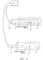
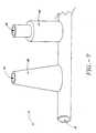
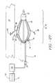
- a sphincter treatment apparatus 10that is used to deliver energy to a treatment site 12 to produce lesions 14 in a sphincter 16, such as the lower esophageal sphincter (LES), comprises a flexible elongate shaft 18, also called shaft 18, coupled to a expansion device 20, in turn coupled with one or more energy delivery devices 22.
- Energy delivery devices 22are configured to be coupled to a power source 24.
- the expansion device 20is configured to be positionable in a sphincter 16 such as the LES or adjacent anatomical structure, such as the cardia of the stomach.
- Expansion device 20is further configured to facilitate the positioning of energy delivery devices 22 to a selectable depth in a sphincter wall 26 or adjoining anatomical structure.
- Expansion device 20has a central longitudinal axis 28 and is moveable between contracted and expanded positions substantially there along. This can be accomplished by a ratchet mechanism as is known to those skilled in the art.
- At least portions of sphincter treatment apparatus 10may be sufficiently radiopaque in order to be visible under fluoroscopy and/or sufficiency echogenic to be visible under ultrasonography.
- sphincter treatment apparatus 10can include visualization capability including, but not limited to, a viewing scope, an expanded eyepiece, fiber optics, video imaging and the like.
- shaft 18is configured to be coupled to expansion device 20 and has sufficient length to position expansion device 20 in the LES and/or stomach using a transoral approach.
- Typical lengths for shaft 18include, but are not limited to, a range of 40-180 cms.
- Shaft 18may be flexible, articulated and steerable and can contain fiber optics (including illumination and imaging fibers, fluid and gas paths, and sensor and electronic cabling.
- shaft 18can be a multi-lumen catheter, as is well known to those skilled in the art.
- An introducing member 21, also called an introducer,may be used to introduce sphincter treatment apparatus 10 into the LES.
- Introducer 21can also function as a sheath for expansion device 20 to keep it in a nondeployed or contracted state during introduction into the LES.
- Introducer 21may be flexible, articulated and steerable and contains a continuous lumen of sufficient diameter to allow the advancement of sphincter treatment apparatus 10.
- Typical diameters for introducer 21include 0.1 to 2 inches, while typical length include 40-180 cms.
- Suitable materials for introducer 21include coil-reinforced plastic tubing as is well known to those skilled in the art.
- the flexible elongate shaft 18is circular in cross section and has proximal and distal extremities (also called ends) 30 and 32.
- Shaft 18may also be coupled at its proximal end 32 to a proximal fitting 34, also called a handle, used by the physician to manipulate sphincter treatment apparatus 10 to reach treatment site 12.
- Shaft 18may have one or more lumens 36, that extend the full length of shaft 18, or part way from shaft proximal end 30 to shaft distal end 32.
- Lumens 36may be used as paths for catheters, guide wires, pull wires, insulated wires and cabling, fluid and optical fibers. Lumens 36 are connected to and/or accessed by connections 38 on or adjacent to proximal fitting 34.
- Connections 38can include luer-lock, lemo connector, swage and other mechanical varieties well known to those skilled in the art. Connections 38 can also include optical/video connections which allow optical and electronic coupling of optical fibers and/or viewing scopes to illuminating sources, eye pieces and video monitors.
- shaft 18may stop at the proximal extremity 40 of expansion device 20 or extend to, or past, the distal extremity 42 of expansion device 20. Suitable materials for shaft 18 include, but are not limited to, polyethylenes, polyurethanes and other medical plastics known to those skilled in the art.
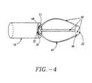
- the expansion device 20comprises one or more elongated arms 44 that are joined at their proximal ends 46 and distal ends 48 to form a basket assembly 50.
- Proximal arm end 46is attached to a supporting structure, which can be the distal end 32 of shaft 18 or a proximal cap 51.
- distal arm end 48is also attached to a supporting structure which can be a basket cap 52 or shaft 18.
- Attached arms 44may form a variety of geometric shapes including, but not limited to, curved, rectangular, trapezoidal and triangular. Arms 44 can have a variety of cross sectional geometries including, but not limited to, circular, rectangular and crescent-shaped.
- arms 44are of a sufficient number (two or more), and have sufficient spring force (0.01 to 0.5 Ibs. force ) so as to collectively exert adequate force on sphincter wall 26 to sufficiently open and efface the folds of sphincter 16 to allow treatment with sphincter treatment apparatus 10, while preventing herniation of sphincter wall 26 into the spaces 53 between arms 44.
- Suitable materials for arms 44include, but are not limited to, spring steel, stainless steel, superelastic shape memory metals such as nitinol or wire reinforced plastic tubing as is well known to those skilled in the art.
- arms 44can have an outwardly bowed shaped memory for expanding the basket assembly into engagement with sphincter wall 26 with the amount of bowing, or camber 54 being selectable from a range 0 to 2 inches from longitudinal axis 28 of basket assembly 50.
- expanded arms 44'are circumferentially and symmetrically spaced-apart.
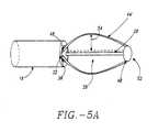
- an expandable member 55which can be a balloon, is coupled to an interior or exterior of basket assembly 50.
- Balloon 55is also coupled to and inflated by lumen 36 using gas or liquid.
- arms 44may be asymmetrically spaced and/or distributed on an arc less than 360°. Also, arms 44 may be preshaped at time of manufacture or shaped by the physician.
- arms 44may also be solid or hollow with a continuous lumen 58 that may be coupled with shaft lumens 36. These coupled lumens provide a path for the delivery of a fluid or electrode delivery member 60 from shaft 18 to any point on basket assembly 50.
- Electrode delivery member 60can be an insulated wire, an insulated guide wire, a plastic-coated stainless steel hypotube with internal wiring or a plastic catheter with internal wiring, all of which are known to those skilled in the art.
- arms 44may also have a partially open channel 62, also called a track 62, that functions as a guide track for electrode delivery member 60. Referring back to FIG.
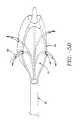
- arms 44may have one or more apertures 64 at any point along their length that permit the controlled placement of energy delivery devices 22 at or into sphincter wall 26.
- apertures 64may have tapered sections 66 or stepped sections 68 in all or part of their length, that are used to control the penetration depth of energy delivery devices 22 into sphincter wall 26.
- apertures 64 in combination with arm lumens 58 and shaft lumens 36may be used for the delivery of cooling solution 70 or electrolytic solution 72 to treatment site 12 as described herein.
- arms 44can also carry a plurality of longitudinally spaced apart radiopaque and or echogenic markers or traces, not shown in the drawings, formed of suitable materials to permit viewing of basket assembly 50 via fluoroscopy or ultrasonography.
- Suitable radiopaque materialsinclude platinum or gold
- suitable echogenic materialsinclude gas filled micro-particles as described in US Patent No's 5,688,490 and 5,205,287.
- Arms 44may also be color-coded to facilitate their identification via visual medical imaging methods and equipment, such as endoscopic methods, which are well known to those skilled in the art.
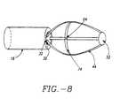
- a supporting member 74may be attached to two or more arms 44.
- Supporting member 74also called a strut, can be attached to arms 44 along a circumference of basket assembly 50 as shown in FIG. 8.
- Apertures 64can extend through radial supporting member 74 in one or more places.
- Radial supporting member 74serves the following functions: i) facilitates opening and effacement of the folds of sphincter 16, ii) enhances contact of Apertures 64 with sphincter wall 26; and, iii) reduces or prevents the tendency of arms 44 to bunch up.
- the cross sectional geometry of radial supporting member 74can be rectangular or circular, though it will be appreciated that other geometries are equally suitable.
- arms 44may be attached to basket cap 52 that in turn, moves freely over shaft 18, but is stopped distally by shaft cap 78.
- One or more pull wires 80are attached to basket cap 52 and also to a movable fitting 82 in proximal fitting 34 of sphincter treatment apparatus 10.
- the camber 54 of basket assembly 50increases to 54', increasing the force and the amount of contact applied by basket assembly 50 to sphincter wall 26 or an adjoining structure.
- Basket assembly 50can also be deflected from side to side using deflection mechanism 80. This allows the physician to remotely point and steer the basket assembly within the body.
- deflection mechanism 84may include a second pull wire 80' attached to shaft cap 78 and also to a movable slide 86 integral to proximal fitting 34.
- suitable power sources 24 and energy delivery devices 22that can be employed in one or more embodiments of the invention include: (i) a radio-frequency (RF) source coupled to an RF electrode, (ii) a coherent source of light coupled to an optical fiber, (iii) an incoherent light source coupled to an optical fiber, (iv) a heated fluid coupled to a catheter with a closed channel configured to receive the heated fluid, (v) a heated fluid coupled to a catheter with an open channel configured to receive the heated fluid, (vi) a cooled fluid coupled to a catheter with a closed channel configured to receive the cooled fluid, (vii) a cooled fluid coupled to a catheter with an open channel configured to receive the cooled fluid, (viii) a cryogenic fluid, (ix) a resistive heating source, (x) a microwave source providing energy from 915 MHz to 2.45 GHz and coupled to a microwave antenna, (xi) an ultrasound power source coupled to an ultrasound emitter, wherein the ultrasound power source
- the power source utilizedis an RF source and energy delivery device 22 is one or more RF electrodes 88, also described as electrodes 88.
- RF sourceand energy delivery device 22 are one or more RF electrodes 88, also described as electrodes 88.
- all of the other herein mentioned power sources and energy delivery devicesare equally applicable to sphincter treatment apparatus 10.
- RF electrode 88may operated in either bipolar or monopolar mode with a ground pad electrode.
- a monopolar mode of delivering RF energya single electrode 88 is used in combination with an indifferent electrode patch that is applied to the body to form the other electrical contact and complete an electrical circuit. Bipolar operation is possible when two or more electrodes 88 are used. Multiple electrodes 88 may be used. These electrodes may be cooled as described herein. Electrodes 88 can be attached to electrode delivery member 60 by the use of soldering methods which are well known to those skilled in the art. Suitable solders include Megabond Solder supplied by the Megatrode Corporation (Milwaukee, Wisconsin).
- Suitable electrolytic solutions 72include saline, solutions of calcium salts, potassium salts, and the like. Electrolytic solutions 72 enhance the electrical conductivity of the targeted tissue at the treatment site 12. When a highly conductive fluid such as electrolytic solution 72 is infused into tissue the electrical resistance of the infused tissue is reduced, in turn, increasing the electrical conductivity of the infused tissue. As a result, there will be little tendency for tissue surrounding electrode 88 to desiccate (a condition described herein that increases the electrical resistance of tissue) resulting in a large increase in the capacity of the tissue to carry RF energy. Referring to FIG. 11, a zone of tissue which has been heavily infused with a concentrated electrolytic solution 72 can become so conductive as to actually act as an enhanced electrode 88'. The effect of enhanced electrode 88' is to increase the amount of current that can be conducted to the treatment site 12, making it possible to heat a much greater volume of tissue in a given time period.
- power source 24which will now be referred to as RF power source 24, may have multiple channels, delivering separately modulated power to each electrode 88. This reduces preferential heating that occurs when more energy is delivered to a zone of greater conductivity and less heating occurs around electrodes 88 which are placed into less conductive tissue. If the level of tissue hydration or the blood infusion rate in the tissue is uniform, a single channel RF power source 24 may be used to provide power for generation of lesions 14 relatively uniform in size.
- Electrodes 88can have a variety of shapes and sizes. Possible shapes include, but are not limited to, circular, rectangular, conical and pyramidal. Electrode surfaces can be smooth or textured and concave or convex. The conductive surface area of electrode 88 can range from 0.1 mm 2 to 100 cm 2 . It will be appreciated that other geometries and surface areas may be equally suitable. Electrodes 88 can be in the shape of needles and of sufficient sharpness and length to penetrate into the smooth muscle of the esophageal wall, sphincter 16 or other anatomical structure. As shown in FIG.s 12 and 13, needle electrodes 90 may be attached to arms 44 and have an insulating layer 92, covering an insulated segment 94 except for an exposed segment 95.
- an insulator or insulation layeris a barrier to either thermal, RF or electrical energy flow.
- Insulated segment 94is of sufficient length to extend into sphincter wall 26 and minimize the transmission of RF energy to a protected site 97 near or adjacent to insulated segment 94 (see FIG. 13).
- Typical lengths for insulated segment 94include, but are not limited to, 1-4 mms.
- Suitable materials for needle electrodes 90include, but are not limited to, 304 stainless steel and,other stainless steels known to those skilled in the art.
- Suitable materials for insulating layer 92include, but are not limited to, polyimides and polyamides.
- basket assembly 50is in a contracted state. Once sphincter treatment apparatus 10 is properly positioned at the treatment site 12, needle electrodes 90 are deployed by expansion of basket assembly 50, resulting in the protrusion of needle electrodes 90 into the smooth muscle tissue of sphincter wall 26 (refer to FIG. 14 ).
- the depth of needle penetrationis selectable from a range of 0.5 to 5 mms and is accomplished by indexing movable fitting 82 so as to change the camber 54 of arm 44 in fixed increments that can be selectable in a range from 0.1 to 4 mms. Needle electrodes 90 are coupled to power source 24 via insulated wire 60.
- needle electrodes 90are advanced out of apertures 64 in basket arms 44 into the smooth muscle of the esophageal wall or other sphincter 16.
- needle electrodes 90are coupled to RF power source 24 by electrode delivery member 60.
- the depth of needle penetrationis selectable via means of stepped sections 66 or tapered sections 68 located in apertures 64.
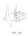
- apertures 64 and needle electrodes 90are configured such that the penetration angle 96 (also called an emergence angle 96) of needle electrode 90 into sphincter wall 26 remains sufficiently constant during the time needle electrode 90 is being inserted into sphincter wall 26, such that there is no tearing or unnecessary trauma to sphincter wall tissue.
- the emergence angle 96 of apertures 64which can vary from 1 to 90°
- the arc radius 98 of the curved section 100 of aperture 64which can vary from 0.001 to 2 inch
- the amount of clearance between the aperture inner diameter 102 and the needle electrode outside diameter 104which can very between 0.001 and 0.1"
- a lubricous coating on electrode delivery member 60such as a Teflon ® or other coatings well known to those skilled in the art.
- Insulated segment 94can be in the form of an sleeve that may be adjustably positioned at the exterior of electrode 90.
- electrode delivery member 60 with attached needle electrodes 90can exit from lumen 36 at distal shaft end 32 and be positioned into contact with sphincter wall 26.
- This processmay be facilitated by use of a hollow guiding member 101, known to those skilled in the art as a guiding catheter, through which electrode delivery member 60 is advanced.
- Guiding catheter 101may also include stepped sections 66 or tapered sections 68 at it distal end to control the depth of penetration of needle electrode 90 into sphincter wall 26.
- RF energy flowing through tissuecauses heating of the tissue due to absorption of the RF energy by the tissue and ohmic heating due to electrical resistance of the tissue. This heating can cause injury to the affected cells and can be substantial enough to cause cell death, a phenomenon also known as cell necrosis.
- cell injurywill include all cellular effects resulting from the delivery of energy from electrode 88 up to, and including, cell necrosis.
- Cell injurycan be accomplished as a relatively simple medical procedure with local anesthesia. Cell injury may proceed to a depth of approximately 1-4 mms from the surface of the mucosal layer of sphincter 16 or that of an adjoining anatomical structure.
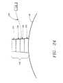
- electrodes 88 and/or apertures 64may be distributed in a variety of patterns along expansion device 20 or basket assembly 50 in order to produce a desired placement and pattern of lesions 14.
- Typical electrode and aperture distribution patternsinclude, but are not limited to, a radial distribution 105 (refer to FIG.18A) or a longitudinal distribution 106 (refer to FIG. 18B). It will be appreciated that other patterns and geometries for electrode and aperture placement, such as a spiral distribution 108 (refer to FIG. 18C) may also be suitable. These electrodes may be cooled as described hereafter.
- FIG. 19is a flow chart illustrating one procedure for using sphincter treatment apparatus 10.
- sphincter treatment apparatus 10is first introduced into the esophagus under local anesthesia.
- Sphincter treatment apparatus 10can be introduced into the esophagus by itself or through a lumen in an endoscope (not shown), such as disclosed in U.S. Patents Nos. 5,448,990 and 5,275,608, incorporated herein by reference, or similar esophageal access device known to those skilled in the art.
- Basket assembly 50is expanded as described herein. This serves to temporarily dilate the LES or sufficiently to efface a portion of or all of the folds of the LES.
- esophageal dilation and subsequent LES fold effacementcan be accomplished by insufflation of the esophagus (a known technique) using gas introduced into the esophagus through shaft lumen 36, or an endoscope or similar esophageal access device as described above.
- insufflation of the esophagusa known technique
- gas introduced into the esophagus through shaft lumen 36or an endoscope or similar esophageal access device as described above.
- the diagnostic phase of the procedurecan be performed using a variety of diagnostic methods, including, but not limited to, the following:
- the delivery of energy to treatment site 12can be conducted under feedback control, manually or by a combination of both.
- Feedback control(described herein) enables sphincter treatment apparatus 10 to be positioned and retained in the esophagus during treatment with minimal attention by the physician.
- Electrodes 88can be multiplexed in order to treat the entire targeted treatment site 12 or only a portion thereof.
- Feedbackcan be included and is achieved by the use of one or more of the following methods: (i) visualization, (ii) impedance measurement, (iii) ultrasonography, (iv) temperature measurement; and, (v) sphincter contractile force measurement via manometry.
- the feedback mechanismpermits the selected on-off switching of different electrodes 88 in a desired pattern, which can be sequential from one electrode 88 to an adjacent electrode 88, or can jump around between non-adjacent electrodes 88.
- Individual electrodes 88are multiplexed and volumetrically controlled by a controller.
- the area and magnitude of cell injury in the LES or sphincter 16can vary. However, it is desirable to deliver sufficient energy to the targeted treatment site 12 to be able to achieve tissue temperatures in the range of 55-95° C and produce lesions 14 at depths ranging from 1-4 mms from the interior surface of the LES or sphincter wall 26. Typical energies delivered to the esophageal wall include, but are not limited to, a range between 100 and 50,000 joules per electrode 88.
- the resulting lesions 14have a sufficient magnitude and area of cell injury to cause an infiltration of lesion 14 by fibroblasts 110, myofibroblasts 112, macrophages 114 and other cells involved in the tissue healing process (refer to FIG. 21). As shown in FIG. 22, these cells cause a contraction of tissue around lesion 14, decreasing its volume and, or altering the biomechanical properties at lesion 14 so as to result in a tightening of LES or sphincter 16. These changes are reflected in transformed lesion 14' shown in FIG. 19B.
- the diameter of lesions 14can vary between 0.1 to 4 mms.
- lesions 14are less than 4 mms in diameter in order to reduce the risk of thermal damage to the mucosal layer.
- a 2 mm diameter lesion 14 centered in the wall of the smooth musclemay provide a 1 mm buffer zone to prevent damage to the mucosa, submucosa and adventitia, while still allowing for cell infiltration and subsequent sphincter tightening on approximately 50% of the thickness of the wall of the smooth muscle (refer to FIG. 23).
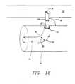
- Each ultrasound transducer 118can include a piezoelectric crystal 120 mounted on a backing material 122 that is in turn, attached to expansion device 20 or basket assembly 50.
- An ultrasound lens 124fabricated on an electrically insulating material 126, is mounted over piezoelectric crystal 120.
- Piezoelectric crystal 120is connected by electrical leads 128 to ultrasound power source 116.
- Each ultrasound transducer 118transmits ultrasound energy into adjacent tissue.
- Ultrasound transducers 118can be in the form of an imaging probe such as Model 21362, manufactured and sold by Hewlett Packard Company, Palo Alto, California. Two ultrasound transducers 118 may be positioned on opposite sides of expansion device 20 or basket assembly 50 to create an image depicting the size and position of lesion 14 in selected sphincter 16.
- lesions 14are predominantly located in the smooth muscle layer of selected sphincter 16 at the depths ranging from 1 to 4 mms from the interior surface of sphincter wall 26. However, lesions 14 can vary both in number and position within sphincter wall 26. It may be desirable to produce a pattern of multiple lesions 14 within the sphincter smooth muscle tissue in order to obtain a selected degree of tightening of the LES or other sphincter 16.
- Typical lesion patterns shown in FIG.s 25A-Dinclude, but are not limited to, (i) a concentric circle of lesions 14 all at fixed depth in the smooth muscle layer evenly spaced along the radial axis of sphincter 16, (ii) a wavy or folded circle of lesions 14 at varying depths in the smooth muscle layer evenly spaced along the radial axis of sphincter 16, (iii) lesions 14 randomly distributed at varying depths in the smooth muscle, but evenly spaced in a radial direction; and, (iv) an eccentric pattern of lesions 14 in one or more radial locations in the smooth muscle wall. Accordingly, the depth of RF and thermal energy penetration sphincter 16 is controlled and selectable.
- the selective application of energy to sphincter 16may be the even penetration of RF energy to the entire targeted treatment site 12, a portion of it, or applying different amounts of RF energy to different sites depending on the condition of sphincter 16. If desired, the area of cell injury can be substantially the same for every treatment event.
- coolingpreserves the mucosal layers of sphincter wall 26 and protects, or otherwise reduces the degree of cell damage to cooled zone 132 in the vicinity of lesion 14.
- thiscan be accomplished through the use of cooling solution 70 that is delivered by apertures 64 which is in fluid communication with shaft lumen 36 that is, in turn, in fluid communication with fluid reservoir 134 and a control unit 136, whose operation is described herein, that controls the delivery of the fluid.
- electrode 88it may also be desirable to cool all or a portion of the electrode 88.
- the rapid delivery of heat through electrode 88may result in the build up of charred biological matter on electrode 88 (from contact with tissue and fluids e.g., blood) that impedes the flow of both thermal and electrical energy from electrode 88 to adjacent tissue and causes an electrical impedance rise beyond a cutoff value set on RF power source 24.
- Cooling of the electrode 88can be accomplished by cooling solution 70 that is delivered by apertures 64 as described previously.
- electrode 88may also be cooled via a fluid channel 138 in electrode 88 that is in fluid communication with fluid reservoir 134 and control unit 136 .
- one or more sensors 140may be positioned adjacent to or on electrode 88 for sensing the temperature of sphincter tissue at treatment site 12. More specifically, sensors 140 permit accurate determination of the surface temperature of sphincter wall 26 at electrode-tissue interface 130. This information can be used to regulate both the delivery of energy and cooling solution 70 to the interior surface of sphincter wall 26. Sensors 140 can be positioned at any position on expansion device 20 or basket assembly 50. Suitable sensors that may be used for sensor 140 include: thermocouples, fiber optics, resistive wires, thermocouple IR detectors, and the like. Suitable thermocouples for sensor 140 include: T type with copper constantene, J type, E type and K types as are well known those skilled in the art.
- Temperature data from sensors 140are fed back to control unit 136 and through an algorithm which is stored within a microprocessor memory of control unit 136. Instructions are sent to an electronically controlled micropump (not shown) to deliver fluid through the fluid lines at the appropriate flow rate and duration to provide control temperature at the electrode-tissue interface 130 (refer to FIG. 27).
- the reservoir of control unit 136may have the ability to control the temperature of the cooling solution 70 by either cooling the fluid or heating the fluid.
- a fluid reservoir 134 of sufficient sizemay be used in which the cooling solution 70 is introduced at a temperature at or near that of the normal body temperature.
- a thermally insulated reservoir 142adequate control of the tissue temperature may be accomplished without need of refrigeration or heating of the cooling solution 70.
- Cooling solution 70 flowis controlled by control unit 136 or another feedback control system (described herein) to provide temperature control at the electrode-tissue interface 130.
- a second diagnostic phasemay be included after the treatment is completed. This provides an indication of LES tightening treatment success, and whether or not a second phase of treatment, to all or only a portion of the esophagus, now or at some later time, should be conducted.
- the second diagnostic phaseis accomplished through one or more of the following methods: (i) visualization, (ii) measuring impedance, (iii) ultrasonography, (iv) temperature measurement, or (v) measurement of LES tension and contractile force via manometry.
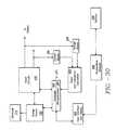
- Sphincter treatment apparatus 10can be coupled to an open or closed loop feedback system.
- an open or closed loop feedback systemcouples sensor 346 to energy source 392.
- electrode 314is one or more RF electrodes 314.
- the temperature of the tissue, or of RF electrode 314is monitored, and the output power of energy source 392 adjusted accordingly.
- the physiciancan, if desired, override the closed or open loop system.
- a microprocessor 394can be included and incorporated in the closed or open loop system to switch power on and off, as well as modulate the power.
- the closed loop systemutilizes microprocessor 394 to serve as a controller, monitor the temperature, adjust the RF power, analyze the result, refeed the result, and then modulate the power.
- a tissue adjacent to RF electrode 314can be maintained at a desired temperature for a selected period of time without causing a shut down of the power circuit to electrode 314 due to the development of excessive electrical impedance at electrode 314 or adjacent tissue as is discussed herein.
- Each RF electrode 314is connected to resources which generate an independent output. The output maintains a selected energy at RF electrode 314 for a selected length of time.
- a control signalis generated by controller 404 that is proportional to the difference between an actual measured value, and a desired value.
- the control signalis used by power circuits 406 to adjust the power output in an appropriate amount in order to maintain the desired power delivered at respective RF electrodes 314.
- temperatures detected at sensor 346provide feedback for maintaining a selected power. Temperature at sensor 346 is used as a safety means to interrupt the delivery of energy when maximum pre-set temperatures are exceeded.
- the actual temperaturesare measured at temperature measurement device 408, and the temperatures are displayed at user interface and display 402.
- a control signalis generated by controller 404 that is proportional to the difference between an actual measured temperature and a desired temperature.
- the control signalis used by power circuits 406 to adjust the power output in an appropriate amount in order to maintain the desired temperature delivered at the sensor 346.
- a multiplexercan be included to measure current, voltage and temperature, at the sensor 346, and energy can be delivered to RF electrode 314 in monopolar or bipolar fashion.
- Controller 404can be a digital or analog controller, or a computer with software.
- controller 404is a computer it can include a CPU coupled through a system bus.
- This systemcan include a keyboard, a disk drive, or other non-volatile memory systems, a display, and other peripherals, as are known in the art.
- Also coupled to the busis a program memory and a data memory.
- User interface and display 402includes operator controls and a display.
- Controller 404can be coupled to imaging systems including, but not limited to, ultrasound, CT scanners, X-ray, MRI, mammographic X-ray and the like. Further, direct visualization and tactile imaging can be utilized.
- controller 404uses the output of current sensor 396 and voltage sensor 398 to maintain a selected power level at RF electrode 314.
- the amount of RF energy deliveredcontrols the amount of power.
- a profile of the power delivered to electrode 314can be incorporated in controller 404 and a preset amount of energy to be delivered may also be profiled.
- Circuitry, software and feedback to controller 404result in process control, the maintenance of the selected power setting which is independent of changes in voltage or current, and is used to change the following process variables: (i) the selected power setting, (ii) the duty cycle (e.g., on-off time), (iii) bipolar or monopolar energy delivery; and, (iv) fluid delivery, including flow rate and pressure.
- process variablesare controlled and varied, while maintaining the desired delivery of power independent of changes in voltage or current, based on temperatures monitored at sensor 346.
- Analog amplifier 410can be a conventional differential amplifier circuit for use with sensor 346.
- the output of analog amplifier 410is sequentially connected by an analog multiplexer 412 to the input of A/D converter 414.
- the output of analog amplifier 410is a voltage which represents the respective sensed temperatures.
- Digitized amplifier output voltagesare supplied by A/D converter 414 to microprocessor 394.
- Microprocessor 394may be a type 68HCII available from Motorola. However, it will be appreciated that any suitable microprocessor or general purpose digital or analog computer can be used to calculate impedance or temperature.
- Microprocessor 394sequentially receives and stores digital representations of impedance and temperature. Each digital value received by microprocessor 394 corresponds to different temperatures and impedances.
- Calculated power and impedance valuescan be indicated on user interface and display 402. Alternatively, or in addition to the numerical indication of power or impedance, calculated impedance and power values can be compared by microprocessor 394 to power and impedance limits. When the values exceed predetermined power or impedance values, a warning can be given on user interface and display 402, and additionally, the delivery of RF energy can be reduced, modified or interrupted. A control signal from microprocessor 394 can modify the power level supplied by energy source 392.
- FIG. 32illustrates a block diagram of a temperature and impedance feedback system that can be used to control the delivery of energy to tissue site 416 by energy source 392 and the delivery of cooling solution 70 to electrode 314 and/or tissue site 416 by flow regulator 418.
- Energyis delivered to RF electrode 314 by energy source 392, and applied to tissue site 416.
- a monitor 420ascertains tissue impedance, based on the energy delivered to tissue, and compares the measured impedance value to a set value. If the measured impedance exceeds the set value, a disabling signal 422 is transmitted to energy source 392, ceasing further delivery of energy to RF electrode 314. If measured impedance is within acceptable limits, energy continues to be applied to the tissue.
- temperature measurement device 408measures the temperature of tissue site 416 and/or RF electrode 314.
- a comparator 424receives a signal representative of the measured temperature and compares this value to a pre-set signal representative of the desired temperature. If the tissue temperature is too high, comparator 424 sends a signal to a flow regulator 418 (connected to an electronically controlled micropump, not shown) representing a need for an increased cooling solution flow rate. If the measured temperature has not exceeded the desired temperature, comparator 424 sends a signal to flow regulator 418 to maintain the cooling solution flow rate at its existing level.
Landscapes
- Health & Medical Sciences (AREA)
- Life Sciences & Earth Sciences (AREA)
- Engineering & Computer Science (AREA)
- Surgery (AREA)
- Animal Behavior & Ethology (AREA)
- General Health & Medical Sciences (AREA)
- Veterinary Medicine (AREA)
- Biomedical Technology (AREA)
- Public Health (AREA)
- Heart & Thoracic Surgery (AREA)
- Nuclear Medicine, Radiotherapy & Molecular Imaging (AREA)
- Medical Informatics (AREA)
- Molecular Biology (AREA)
- Otolaryngology (AREA)
- Physics & Mathematics (AREA)
- Plasma & Fusion (AREA)
- Pulmonology (AREA)
- Radiology & Medical Imaging (AREA)
- Cardiology (AREA)
- Anesthesiology (AREA)
- Emergency Medicine (AREA)
- Hematology (AREA)
- Neurology (AREA)
- Electromagnetism (AREA)
- Neurosurgery (AREA)
- Vascular Medicine (AREA)
- Surgical Instruments (AREA)
Abstract
Description
Claims (9)
- A sphincter treatment apparatus (10) comprising
an expansion device (20) including a plurality of arms (44), each arm of the pluralityincluding a distal section (46) and a proximal section (48) with each of the plurality of arm distalsections being coupled to each other and each of the arm proximal sections being coupled to each other, whereinthe expansion device is configured to be introduced in the sphincter (16) in a non-deployedstate, and to expand to a deployed stateto at least partially dilate the sphincter and
one or more energy delivery devices (22) coupled to the expansion device, at least oneof the energy delivery devices being controllably advanceable from a retracted position within an arm of the expansion device toan extended position outward of the arm of the expansion device to introduce theenergy delivery deviceinto the sphincter. - An apparatus as in claim 1, further comprising
one or more temperature sensors (140) coupled to the energy delivery devices (22). - An apparatus as in claim 1, further comprising
apertures (64) disposed on the arms (44) sized andconfigured to direct a cooling fluid (70) to cool the energy delivery devices (22). - An apparatus as in claim 1, further comprising
a visualization device coupled to the expansion device (20). - An apparatus as in claim 1,
wherein at least one energy delivery devices (22) has a distal portion configured to beadvanceable into the sphincter (16). - An apparatus as in claim 1,
wherein at least one of the energy delivery devices (22) is a radiofrequency electrode (88). - An apparatus as in claim 1, further comprising
an expandable member (55) positioned within an interior defined by the expansion device (20). - An apparatus as in claim 7,
wherein the expandable member is a balloon. - An apparatus as in claim 1,
wherein the sphincter (16) is the lower esophageal sphincter.
Applications Claiming Priority (3)
| Application Number | Priority Date | Filing Date | Title |
|---|---|---|---|
| US26316 | 1998-02-19 | ||
| US09/026,316US6056744A (en) | 1994-06-24 | 1998-02-19 | Sphincter treatment apparatus |
| PCT/US1999/003752WO1999042044A1 (en) | 1998-02-19 | 1999-02-19 | Electrosurgical sphincter treatment apparatus |
Publications (2)
| Publication Number | Publication Date |
|---|---|
| EP1056403A1 EP1056403A1 (en) | 2000-12-06 |
| EP1056403B1true EP1056403B1 (en) | 2005-01-19 |
Family
ID=21831130
Family Applications (1)
| Application Number | Title | Priority Date | Filing Date |
|---|---|---|---|
| EP99908327AExpired - LifetimeEP1056403B1 (en) | 1998-02-19 | 1999-02-19 | Electrosurgical sphincter treatment apparatus |
Country Status (8)
| Country | Link |
|---|---|
| US (2) | US8894646B2 (en) |
| EP (1) | EP1056403B1 (en) |
| JP (1) | JP3879055B2 (en) |
| AT (1) | ATE287242T1 (en) |
| AU (1) | AU752243B2 (en) |
| CA (1) | CA2319517A1 (en) |
| DE (1) | DE69923291T2 (en) |
| WO (1) | WO1999042044A1 (en) |
Cited By (2)
| Publication number | Priority date | Publication date | Assignee | Title |
|---|---|---|---|---|
| AU2018206803B2 (en)* | 2013-02-21 | 2020-05-28 | Stryker Corporation | Cannula for tissue ablation |
| US11452561B2 (en) | 2013-02-21 | 2022-09-27 | Stryker Corporation | Tissue ablation cannula assembly |
Families Citing this family (67)
| Publication number | Priority date | Publication date | Assignee | Title |
|---|---|---|---|---|
| JPS6092795A (en)* | 1983-10-27 | 1985-05-24 | 松下電器産業株式会社 | Dehydrating washer |
| US6409722B1 (en) | 1998-07-07 | 2002-06-25 | Medtronic, Inc. | Apparatus and method for creating, maintaining, and controlling a virtual electrode used for the ablation of tissue |
| US6409723B1 (en)* | 1999-04-02 | 2002-06-25 | Stuart D. Edwards | Treating body tissue by applying energy and substances |
| US7811282B2 (en) | 2000-03-06 | 2010-10-12 | Salient Surgical Technologies, Inc. | Fluid-assisted electrosurgical devices, electrosurgical unit with pump and methods of use thereof |
| US8048070B2 (en) | 2000-03-06 | 2011-11-01 | Salient Surgical Technologies, Inc. | Fluid-assisted medical devices, systems and methods |
| US6428504B1 (en)* | 2000-04-06 | 2002-08-06 | Varian Medical Systems, Inc. | Multipurpose template and needles for the delivery and monitoring of multiple minimally invasive therapies |
| US6638277B2 (en)* | 2000-07-06 | 2003-10-28 | Scimed Life Systems, Inc. | Tumor ablation needle with independently activated and independently traversing tines |
| US7070596B1 (en)* | 2000-08-09 | 2006-07-04 | Arthrocare Corporation | Electrosurgical apparatus having a curved distal section |
| US7306591B2 (en)* | 2000-10-02 | 2007-12-11 | Novasys Medical, Inc. | Apparatus and methods for treating female urinary incontinence |
| AU6314301A (en)* | 2000-11-16 | 2002-05-27 | Robert A Ganz | System and method of treating abnormal tissue in the human esophagus |
| EP1435867B1 (en) | 2001-09-05 | 2010-11-17 | Salient Surgical Technologies, Inc. | Fluid-assisted medical devices and systems |
| US7226448B2 (en)* | 2001-12-04 | 2007-06-05 | Estech, Inc. (Endoscopic Technologies, Inc.) | Cardiac treatment devices and methods |
| US7653438B2 (en) | 2002-04-08 | 2010-01-26 | Ardian, Inc. | Methods and apparatus for renal neuromodulation |
| US8347891B2 (en)* | 2002-04-08 | 2013-01-08 | Medtronic Ardian Luxembourg S.A.R.L. | Methods and apparatus for performing a non-continuous circumferential treatment of a body lumen |
| AUPS226402A0 (en)* | 2002-05-13 | 2002-06-13 | Advanced Metal Coatings Pty Limited | An ablation catheter |
| US7257450B2 (en) | 2003-02-13 | 2007-08-14 | Coaptus Medical Corporation | Systems and methods for securing cardiovascular tissue |
| US7270656B2 (en) | 2003-11-07 | 2007-09-18 | Visualase, Inc. | Cooled laser fiber for improved thermal therapy |
| US7473252B2 (en) | 2004-10-07 | 2009-01-06 | Coaptus Medical Corporation | Systems and methods for shrinking and/or securing cardiovascular tissue |
| GB0620061D0 (en)* | 2006-10-10 | 2006-11-22 | Medical Device Innovations Ltd | Oesophageal treatment apparatus and method |
| US9403029B2 (en) | 2007-07-18 | 2016-08-02 | Visualase, Inc. | Systems and methods for thermal therapy |
| US8483831B1 (en) | 2008-02-15 | 2013-07-09 | Holaira, Inc. | System and method for bronchial dilation |
| JP5865702B2 (en)* | 2008-04-03 | 2016-02-17 | メドトロニック, インク.Medtronic, Inc. | System and method for hyperthermia treatment |
| JP2011519699A (en) | 2008-05-09 | 2011-07-14 | インノブアトイブエ プルモナルイ ソルウトイオンス,インコーポレイティッド | Systems, assemblies and methods for treatment of bronchial trees |
| US9474565B2 (en) | 2009-09-22 | 2016-10-25 | Mederi Therapeutics, Inc. | Systems and methods for treating tissue with radiofrequency energy |
| US9775664B2 (en) | 2009-09-22 | 2017-10-03 | Mederi Therapeutics, Inc. | Systems and methods for treating tissue with radiofrequency energy |
| US9750563B2 (en) | 2009-09-22 | 2017-09-05 | Mederi Therapeutics, Inc. | Systems and methods for treating tissue with radiofrequency energy |
| WO2011060200A1 (en)* | 2009-11-11 | 2011-05-19 | Innovative Pulmonary Solutions, Inc. | Systems, apparatuses, and methods for treating tissue and controlling stenosis |
| CN105147347B (en)* | 2010-03-06 | 2018-06-12 | 新融合血管系统有限公司 | Recycle catheter kit |
| US9545323B2 (en) | 2010-11-16 | 2017-01-17 | W. L. Gore & Associates, Inc. | Fenestration devices, systems, and methods |
| EP2665433B1 (en) | 2011-01-19 | 2021-03-10 | Fractyl Laboratories Inc. | Devices for the treatment of tissue |
| US9492113B2 (en) | 2011-07-15 | 2016-11-15 | Boston Scientific Scimed, Inc. | Systems and methods for monitoring organ activity |
| WO2013052852A1 (en)* | 2011-10-07 | 2013-04-11 | Boston Scientific Scimed, Inc. | Methods and systems for detection and thermal treatment of lower urinary tract conditions |
| US10076383B2 (en)* | 2012-01-25 | 2018-09-18 | Covidien Lp | Electrosurgical device having a multiplexer |
| CA2865567C (en) | 2012-02-27 | 2022-10-11 | Fractyl Laboratories, Inc. | Heat ablation systems, devices and methods for the treatment of tissue |
| WO2015148541A1 (en)* | 2014-03-24 | 2015-10-01 | Fractyl Laboratories, Inc. | Injectate delivery devices, systems and methods |
| EP3711810B1 (en)* | 2012-04-19 | 2023-02-22 | Fractyl Health, Inc. | Tissue expansion systems |
| US9108029B2 (en) | 2012-05-21 | 2015-08-18 | Nfusion Vascular Systems, Llc | Recovery catheter assembly and method |
| EP3714826A1 (en) | 2012-07-30 | 2020-09-30 | Fractyl Laboratories, Inc. | Electrical energy ablation systems and devices for the treatment of tissue |
| WO2014026055A1 (en) | 2012-08-09 | 2014-02-13 | Fractyl Laboratories Inc. | Ablation systems, devices and methods for the treatment of tissue |
| EP2903626A4 (en) | 2012-10-05 | 2016-10-19 | Fractyl Lab Inc | METHODS, SYSTEMS AND DEVICES FOR REALIZING MULTIPLE TREATMENTS ON A PATIENT |
| JP6372492B2 (en)* | 2013-02-05 | 2018-08-15 | ハンドク カロス メディカル インコーポレイテッド | Denervation catheter |
| EP3003461B1 (en) | 2013-06-04 | 2019-05-01 | Fractyl Laboratories, Inc. | Systems and devices for reducing the luminal surface area of the gastrointestinal tract |
| EP3043732B1 (en) | 2013-09-12 | 2021-04-07 | Fractyl Laboratories, Inc. | Systems and devices for treatment of target tissue |
| KR102284469B1 (en) | 2013-11-22 | 2021-08-02 | 프랙틸 헬쓰, 인코포레이티드 | Systems, devices and methods for the creation of a therapeutic restriction in the gastrointestinal tract |
| US10959774B2 (en) | 2014-03-24 | 2021-03-30 | Fractyl Laboratories, Inc. | Injectate delivery devices, systems and methods |
| US11185367B2 (en) | 2014-07-16 | 2021-11-30 | Fractyl Health, Inc. | Methods and systems for treating diabetes and related diseases and disorders |
| EP3169260B1 (en) | 2014-07-16 | 2019-09-25 | Fractyl Laboratories, Inc. | System for treating diabetes and related diseases and disorders |
| US9757535B2 (en) | 2014-07-16 | 2017-09-12 | Fractyl Laboratories, Inc. | Systems, devices and methods for performing medical procedures in the intestine |
| US20160346520A1 (en)* | 2015-05-28 | 2016-12-01 | Dan B. French | Medical Instrument for Injecting an Agent |
| US10376170B2 (en) | 2015-08-10 | 2019-08-13 | Boston Scientific Scimed, Inc. | Catheter with annular lumen to provide distal flushing |
| US10864040B2 (en) | 2015-12-29 | 2020-12-15 | Warsaw Orthopedic, Inc. | Multi-probe system using bipolar probes and methods of using the same |
| US20170367760A1 (en) | 2016-04-12 | 2017-12-28 | Seth Crozier | Esophageal ablation technology |
| US11172821B2 (en) | 2016-04-28 | 2021-11-16 | Medtronic Navigation, Inc. | Navigation and local thermometry |
| EP3522807B1 (en) | 2016-10-04 | 2025-07-09 | Avent, Inc. | Cooled rf probes |
| EP3315086B1 (en)* | 2016-10-28 | 2020-06-17 | Ablacon Inc. | Elongated medical device suitable for intravascular insertion and method of making such a device |
| US11896823B2 (en) | 2017-04-04 | 2024-02-13 | Btl Healthcare Technologies A.S. | Method and device for pelvic floor tissue treatment |
| US12220157B2 (en)* | 2017-06-05 | 2025-02-11 | St. Jude Medical, Cardiology Division, Inc. | Pulmonary antrum radial-linear ablation devices |
| US11173281B2 (en)* | 2017-06-19 | 2021-11-16 | W. L. Gore & Associates, Inc. | Fenestration devices, systems, and methods |
| CN110809435B (en)* | 2017-07-04 | 2023-12-15 | 泰尔茂株式会社 | Medical device and treatment method |
| US11648047B2 (en) | 2017-10-06 | 2023-05-16 | Vive Scientific, Llc | System and method to treat obstructive sleep apnea |
| US12220594B2 (en)* | 2017-10-19 | 2025-02-11 | Robert Der-Yang Tien | System and method for treating cancer |
| US10980599B2 (en) | 2018-07-05 | 2021-04-20 | Avent, Inc. | System and method for adjusting available power per probe during an ablation procedure |
| US20210186601A1 (en)* | 2019-12-23 | 2021-06-24 | Ethicon, Inc. | Transesophageal Catheter for Thermal Protection of the Esophagus |
| JP7329624B2 (en)* | 2020-01-09 | 2023-08-18 | オリンパス株式会社 | Endoscopic treatment instrument and endoscopic treatment method |
| EP4090282A4 (en) | 2020-01-15 | 2024-02-21 | Fractyl Health, Inc. | AUTOMATIC FABRIC TREATMENT DEVICES, SYSTEMS AND METHODS |
| US20210267669A1 (en)* | 2020-02-28 | 2021-09-02 | Olympus Corporation | Device for treating gastroesophageal reflux disease and method for treating gastroesophageal reflux disease |
| JP7565707B2 (en)* | 2020-05-14 | 2024-10-11 | 勇 佐伯 | Esophageal atresia treatment device |
Citations (1)
| Publication number | Priority date | Publication date | Assignee | Title |
|---|---|---|---|---|
| WO1997033524A1 (en)* | 1996-03-15 | 1997-09-18 | Rita Medical Systems, Inc. | Multiple antenna ablation apparatus and method with cooling element |
Family Cites Families (181)
| Publication number | Priority date | Publication date | Assignee | Title |
|---|---|---|---|---|
| US1798902A (en) | 1928-11-05 | 1931-03-31 | Edwin M Raney | Surgical instrument |
| US3517128A (en) | 1968-02-08 | 1970-06-23 | James R Hines | Surgical expanding arm dilator |
| US3901241A (en) | 1973-05-31 | 1975-08-26 | Al Corp Du | Disposable cryosurgical instrument |
| DE2513868C2 (en) | 1974-04-01 | 1982-11-04 | Olympus Optical Co., Ltd., Tokyo | Bipolar electrodiathermy forceps |
| US4196724A (en) | 1978-01-31 | 1980-04-08 | Frecker William H | Tongue locking device |
| WO1981003271A1 (en) | 1980-05-13 | 1981-11-26 | American Hospital Supply Corp | A multipolar electrosurgical device |
| JPS5755573A (en) | 1980-09-18 | 1982-04-02 | Olympus Optical Co Ltd | Cassette storing device |
| US4565200A (en) | 1980-09-24 | 1986-01-21 | Cosman Eric R | Universal lesion and recording electrode system |
| US4411266A (en) | 1980-09-24 | 1983-10-25 | Cosman Eric R | Thermocouple radio frequency lesion electrode |
| US5542915A (en) | 1992-08-12 | 1996-08-06 | Vidamed, Inc. | Thermal mapping catheter with ultrasound probe |
| US5385544A (en) | 1992-08-12 | 1995-01-31 | Vidamed, Inc. | BPH ablation method and apparatus |
| US5370675A (en) | 1992-08-12 | 1994-12-06 | Vidamed, Inc. | Medical probe device and method |
| US5435805A (en) | 1992-08-12 | 1995-07-25 | Vidamed, Inc. | Medical probe device with optical viewing capability |
| US5421819A (en) | 1992-08-12 | 1995-06-06 | Vidamed, Inc. | Medical probe device |
| US4601296A (en) | 1983-10-07 | 1986-07-22 | Yeda Research And Development Co., Ltd. | Hyperthermia apparatus |
| US4705041A (en) | 1984-07-06 | 1987-11-10 | Kim Il G | Dilator for Sphincter of Oddi |
| US5019075A (en) | 1984-10-24 | 1991-05-28 | The Beth Israel Hospital | Method and apparatus for angioplasty |
| US5215103A (en) | 1986-11-14 | 1993-06-01 | Desai Jawahar M | Catheter for mapping and ablation and method therefor |
| US5231995A (en) | 1986-11-14 | 1993-08-03 | Desai Jawahar M | Method for catheter mapping and ablation |
| US5365926A (en) | 1986-11-14 | 1994-11-22 | Desai Jawahar M | Catheter for mapping and ablation and method therefor |
| US4790310A (en) | 1987-02-04 | 1988-12-13 | Robert Ginsburg | Laser catheter having wide angle sweep |
| US4901737A (en) | 1987-04-13 | 1990-02-20 | Toone Kent J | Method and therapeutic apparatus for reducing snoring |
| US4943290A (en) | 1987-06-23 | 1990-07-24 | Concept Inc. | Electrolyte purging electrode tip |
| JPS6446056U (en) | 1987-09-17 | 1989-03-22 | ||
| US5588432A (en) | 1988-03-21 | 1996-12-31 | Boston Scientific Corporation | Catheters for imaging, sensing electrical potentials, and ablating tissue |
| US4907589A (en) | 1988-04-29 | 1990-03-13 | Cosman Eric R | Automatic over-temperature control apparatus for a therapeutic heating device |
| DE3821544C2 (en) | 1988-06-25 | 1994-04-28 | H Prof Dr Med Just | Dilatation catheter |
| US4947842A (en) | 1988-09-22 | 1990-08-14 | Medical Engineering And Development Institute, Inc. | Method and apparatus for treating tissue with first and second modalities |
| US4906203A (en) | 1988-10-24 | 1990-03-06 | General Motors Corporation | Electrical connector with shorting clip |
| US4955377A (en) | 1988-10-28 | 1990-09-11 | Lennox Charles D | Device and method for heating tissue in a patient's body |
| US4966597A (en) | 1988-11-04 | 1990-10-30 | Cosman Eric R | Thermometric cardiac tissue ablation electrode with ultra-sensitive temperature detection |
| DE3838840C2 (en) | 1988-11-17 | 1997-02-20 | Leibinger Gmbh | High frequency coagulation device for surgical purposes |
| CA1332905C (en) | 1989-03-10 | 1994-11-08 | John A. Murchie | Method and apparatus for treatment of snoring |
| US4976711A (en) | 1989-04-13 | 1990-12-11 | Everest Medical Corporation | Ablation catheter with selectively deployable electrodes |
| US5078717A (en) | 1989-04-13 | 1992-01-07 | Everest Medical Corporation | Ablation catheter with selectively deployable electrodes |
| US5125928A (en) | 1989-04-13 | 1992-06-30 | Everest Medical Corporation | Ablation catheter with selectively deployable electrodes |
| US5057107A (en) | 1989-04-13 | 1991-10-15 | Everest Medical Corporation | Ablation catheter with selectively deployable electrodes |
| DE3915636C1 (en) | 1989-05-12 | 1990-04-26 | Sass, Wolfgang, Dr. | |
| US5084044A (en) | 1989-07-14 | 1992-01-28 | Ciron Corporation | Apparatus for endometrial ablation and method of using same |
| AU6042690A (en)* | 1989-08-01 | 1991-03-11 | Claudio D'orazi | Percutaneous mechanical dilating catheter for cardiac valves and blood vessels |
| EP0490979B1 (en) | 1989-09-08 | 1996-11-13 | Boston Scientific Corporation | Physiologic low stress angioplasty |
| US5035696A (en) | 1990-02-02 | 1991-07-30 | Everest Medical Corporation | Electrosurgical instrument for conducting endoscopic retrograde sphincterotomy |
| US5205287A (en) | 1990-04-26 | 1993-04-27 | Hoechst Aktiengesellschaft | Ultrasonic contrast agents, processes for their preparation and the use thereof as diagnostic and therapeutic agents |
| US5122137A (en) | 1990-04-27 | 1992-06-16 | Boston Scientific Corporation | Temperature controlled rf coagulation |
| US5236413B1 (en) | 1990-05-07 | 1996-06-18 | Andrew J Feiring | Method and apparatus for inducing the permeation of medication into internal tissue |
| US5190540A (en) | 1990-06-08 | 1993-03-02 | Cardiovascular & Interventional Research Consultants, Inc. | Thermal balloon angioplasty |
| US5083565A (en) | 1990-08-03 | 1992-01-28 | Everest Medical Corporation | Electrosurgical instrument for ablating endocardial tissue |
| US5100423A (en) | 1990-08-21 | 1992-03-31 | Medical Engineering & Development Institute, Inc. | Ablation catheter |
| US5422926A (en) | 1990-09-05 | 1995-06-06 | Photoelectron Corporation | X-ray source with shaped radiation pattern |
| JPH05506174A (en) | 1990-09-14 | 1993-09-16 | アメリカン・メディカル・システムズ・インコーポレーテッド | Combined hyperthermia and dilatation catheter |
| AU646892B2 (en) | 1990-10-03 | 1994-03-10 | Ernest Truffer | Snoring prevention device |
| US5256138A (en) | 1990-10-04 | 1993-10-26 | The Birtcher Corporation | Electrosurgical handpiece incorporating blade and conductive gas functionality |
| US5088979A (en) | 1990-10-11 | 1992-02-18 | Wilson-Cook Medical Inc. | Method for esophageal invagination and devices useful therein |
| US5190541A (en) | 1990-10-17 | 1993-03-02 | Boston Scientific Corporation | Surgical instrument and method |
| DE9190181U1 (en) | 1990-12-10 | 1993-07-29 | Howmedica Inc. (n.d.Ges.d.Staates Delaware), New York, N.Y. | Device for interstitial laser energy delivery |
| US5368557A (en) | 1991-01-11 | 1994-11-29 | Baxter International Inc. | Ultrasonic ablation catheter device having multiple ultrasound transmission members |
| US5094233A (en) | 1991-01-11 | 1992-03-10 | Brennan Louis G | Turbinate sheath device |
| US5370901A (en) | 1991-02-15 | 1994-12-06 | Bracco International B.V. | Compositions for increasing the image contrast in diagnostic investigations of the digestive tract of patients |
| US5156151A (en) | 1991-02-15 | 1992-10-20 | Cardiac Pathways Corporation | Endocardial mapping and ablation system and catheter probe |
| US5409453A (en) | 1992-08-12 | 1995-04-25 | Vidamed, Inc. | Steerable medical probe with stylets |
| US5465717A (en) | 1991-02-15 | 1995-11-14 | Cardiac Pathways Corporation | Apparatus and Method for ventricular mapping and ablation |
| US5345936A (en) | 1991-02-15 | 1994-09-13 | Cardiac Pathways Corporation | Apparatus with basket assembly for endocardial mapping |
| US5275610A (en) | 1991-05-13 | 1994-01-04 | Cook Incorporated | Surgical retractors and method of use |
| WO1992021285A1 (en) | 1991-05-24 | 1992-12-10 | Ep Technologies, Inc. | Combination monophasic action potential/ablation catheter and high-performance filter system |
| US5383917A (en) | 1991-07-05 | 1995-01-24 | Jawahar M. Desai | Device and method for multi-phase radio-frequency ablation |
| US5275608A (en) | 1991-10-16 | 1994-01-04 | Implemed, Inc. | Generic endoscopic instrument |
| US5363861A (en) | 1991-11-08 | 1994-11-15 | Ep Technologies, Inc. | Electrode tip assembly with variable resistance to bending |
| AU3128593A (en) | 1991-11-08 | 1993-06-07 | Ep Technologies Inc | Radiofrequency ablation with phase sensitive power detection |
| US5328467A (en) | 1991-11-08 | 1994-07-12 | Ep Technologies, Inc. | Catheter having a torque transmitting sleeve |
| US5257451A (en) | 1991-11-08 | 1993-11-02 | Ep Technologies, Inc. | Method of making durable sleeve for enclosing a bendable electrode tip assembly |
| CA2106410C (en) | 1991-11-08 | 2004-07-06 | Stuart D. Edwards | Ablation electrode with insulated temperature sensing elements |
| US5275162A (en) | 1991-11-08 | 1994-01-04 | Ep Technologies, Inc. | Valve mapping catheter |
| US5197964A (en) | 1991-11-12 | 1993-03-30 | Everest Medical Corporation | Bipolar instrument utilizing one stationary electrode and one movable electrode |
| US5197963A (en) | 1991-12-02 | 1993-03-30 | Everest Medical Corporation | Electrosurgical instrument with extendable sheath for irrigation and aspiration |
| US5242441A (en) | 1992-02-24 | 1993-09-07 | Boaz Avitall | Deflectable catheter with rotatable tip electrode |
| US5263493A (en) | 1992-02-24 | 1993-11-23 | Boaz Avitall | Deflectable loop electrode array mapping and ablation catheter for cardiac chambers |
| US5480644A (en) | 1992-02-28 | 1996-01-02 | Jsf Consultants Ltd. | Use of injectable biomaterials for the repair and augmentation of the anal sphincters |
| US5281216A (en) | 1992-03-31 | 1994-01-25 | Valleylab, Inc. | Electrosurgical bipolar treating apparatus |
| US5281217A (en) | 1992-04-13 | 1994-01-25 | Ep Technologies, Inc. | Steerable antenna systems for cardiac ablation that minimize tissue damage and blood coagulation due to conductive heating patterns |
| WO1993020886A1 (en) | 1992-04-13 | 1993-10-28 | Ep Technologies, Inc. | Articulated systems for cardiac ablation |
| US5314466A (en) | 1992-04-13 | 1994-05-24 | Ep Technologies, Inc. | Articulated unidirectional microwave antenna systems for cardiac ablation |
| WO1993020768A1 (en) | 1992-04-13 | 1993-10-28 | Ep Technologies, Inc. | Steerable microwave antenna systems for cardiac ablation |
| US5277201A (en) | 1992-05-01 | 1994-01-11 | Vesta Medical, Inc. | Endometrial ablation apparatus and method |
| US5562720A (en) | 1992-05-01 | 1996-10-08 | Vesta Medical, Inc. | Bipolar/monopolar endometrial ablation device and method |
| US5443470A (en) | 1992-05-01 | 1995-08-22 | Vesta Medical, Inc. | Method and apparatus for endometrial ablation |
| US5281218A (en) | 1992-06-05 | 1994-01-25 | Cardiac Pathways Corporation | Catheter having needle electrode for radiofrequency ablation |
| US5324284A (en) | 1992-06-05 | 1994-06-28 | Cardiac Pathways, Inc. | Endocardial mapping and ablation system utilizing a separately controlled ablation catheter and method |
| US5254126A (en) | 1992-06-24 | 1993-10-19 | Ethicon, Inc. | Endoscopic suture punch |
| WO1994002077A2 (en) | 1992-07-15 | 1994-02-03 | Angelase, Inc. | Ablation catheter system |
| US5514131A (en) | 1992-08-12 | 1996-05-07 | Stuart D. Edwards | Method for the ablation treatment of the uvula |
| US5672153A (en) | 1992-08-12 | 1997-09-30 | Vidamed, Inc. | Medical probe device and method |
| US5470308A (en) | 1992-08-12 | 1995-11-28 | Vidamed, Inc. | Medical probe with biopsy stylet |
| US5556377A (en) | 1992-08-12 | 1996-09-17 | Vidamed, Inc. | Medical probe apparatus with laser and/or microwave monolithic integrated circuit probe |
| US5486161A (en) | 1993-02-02 | 1996-01-23 | Zomed International | Medical probe device and method |
| US5456662A (en) | 1993-02-02 | 1995-10-10 | Edwards; Stuart D. | Method for reducing snoring by RF ablation of the uvula |
| US5484400A (en) | 1992-08-12 | 1996-01-16 | Vidamed, Inc. | Dual channel RF delivery system |
| US5542916A (en) | 1992-08-12 | 1996-08-06 | Vidamed, Inc. | Dual-channel RF power delivery system |
| US5720718A (en) | 1992-08-12 | 1998-02-24 | Vidamed, Inc. | Medical probe apparatus with enhanced RF, resistance heating, and microwave ablation capabilities |
| US5309910A (en)* | 1992-09-25 | 1994-05-10 | Ep Technologies, Inc. | Cardiac mapping and ablation systems |
| US5293869A (en) | 1992-09-25 | 1994-03-15 | Ep Technologies, Inc. | Cardiac probe with dynamic support for maintaining constant surface contact during heart systole and diastole |
| US5313943A (en) | 1992-09-25 | 1994-05-24 | Ep Technologies, Inc. | Catheters and methods for performing cardiac diagnosis and treatment |
| US5401272A (en) | 1992-09-25 | 1995-03-28 | Envision Surgical Systems, Inc. | Multimodality probe with extendable bipolar electrodes |
| US5471982A (en) | 1992-09-29 | 1995-12-05 | Ep Technologies, Inc. | Cardiac mapping and ablation systems |
| US5334196A (en) | 1992-10-05 | 1994-08-02 | United States Surgical Corporation | Endoscopic fastener remover |
| US5415657A (en) | 1992-10-13 | 1995-05-16 | Taymor-Luria; Howard | Percutaneous vascular sealing method |
| US5383853A (en) | 1992-11-12 | 1995-01-24 | Medtronic, Inc. | Rapid exchange catheter |
| EP0719113A1 (en) | 1992-11-13 | 1996-07-03 | American Cardiac Ablation Co., Inc. | Fluid cooled electrosurgical probe |
| US5342357A (en) | 1992-11-13 | 1994-08-30 | American Cardiac Ablation Co., Inc. | Fluid cooled electrosurgical cauterization system |
| US5348554A (en) | 1992-12-01 | 1994-09-20 | Cardiac Pathways Corporation | Catheter for RF ablation with cooled electrode |
| US5409483A (en) | 1993-01-22 | 1995-04-25 | Jeffrey H. Reese | Direct visualization surgical probe |
| IL108532A (en) | 1993-02-02 | 1997-07-13 | Vidamed Inc | Transurethral needle ablation device |
| DE4303882C2 (en) | 1993-02-10 | 1995-02-09 | Kernforschungsz Karlsruhe | Combination instrument for separation and coagulation for minimally invasive surgery |
| US5636634A (en) | 1993-03-16 | 1997-06-10 | Ep Technologies, Inc. | Systems using guide sheaths for introducing, deploying, and stabilizing cardiac mapping and ablation probes |
| US5330488A (en)* | 1993-03-23 | 1994-07-19 | Goldrath Milton H | Verres needle suturing kit |
| US5403311A (en) | 1993-03-29 | 1995-04-04 | Boston Scientific Corporation | Electro-coagulation and ablation and other electrotherapeutic treatments of body tissue |
| US5336222A (en) | 1993-03-29 | 1994-08-09 | Boston Scientific Corporation | Integrated catheter for diverse in situ tissue therapy |
| JPH07507709A (en) | 1993-04-07 | 1995-08-31 | カーディアック パスウェイズ コーポレイション | Apparatus and method for ventricular mapping and ablation |
| US5365945A (en) | 1993-04-13 | 1994-11-22 | Halstrom Leonard W | Adjustable dental applicance for treatment of snoring and obstructive sleep apnea |
| JP3587848B2 (en) | 1993-06-10 | 2004-11-10 | ミア エイ イムラン | Transurethral RF resection device |
| US5860974A (en) | 1993-07-01 | 1999-01-19 | Boston Scientific Corporation | Heart ablation catheter with expandable electrode and method of coupling energy to an electrode on a catheter shaft |
| DE4323585A1 (en) | 1993-07-14 | 1995-01-19 | Delma Elektro Med App | Bipolar high-frequency surgical instrument |
| US5738096A (en) | 1993-07-20 | 1998-04-14 | Biosense, Inc. | Cardiac electromechanics |
| US5582609A (en) | 1993-10-14 | 1996-12-10 | Ep Technologies, Inc. | Systems and methods for forming large lesions in body tissue using curvilinear electrode elements |
| WO1995010322A1 (en) | 1993-10-15 | 1995-04-20 | Ep Technologies, Inc. | Creating complex lesion patterns in body tissue |
| US5433739A (en) | 1993-11-02 | 1995-07-18 | Sluijter; Menno E. | Method and apparatus for heating an intervertebral disc for relief of back pain |
| US5599346A (en) | 1993-11-08 | 1997-02-04 | Zomed International, Inc. | RF treatment system |
| US5536267A (en) | 1993-11-08 | 1996-07-16 | Zomed International | Multiple electrode ablation apparatus |
| US5683384A (en) | 1993-11-08 | 1997-11-04 | Zomed | Multiple antenna ablation apparatus |
| US5458597A (en) | 1993-11-08 | 1995-10-17 | Zomed International | Device for treating cancer and non-malignant tumors and methods |
| US5472441A (en) | 1993-11-08 | 1995-12-05 | Zomed International | Device for treating cancer and non-malignant tumors and methods |
| US5507743A (en) | 1993-11-08 | 1996-04-16 | Zomed International | Coiled RF electrode treatment apparatus |
| WO1995020345A1 (en) | 1994-01-28 | 1995-08-03 | Ep Technologies, Inc. | Minimizing blood contact in cardiac tissue measurements |
| US5423812A (en) | 1994-01-31 | 1995-06-13 | Ellman; Alan G. | Electrosurgical stripping electrode for palatopharynx tissue |
| US5448990A (en) | 1994-02-15 | 1995-09-12 | Very Inventive Physicians, Inc. | Endoscope viewing cannula and surgical techniques |
| US5443457A (en) | 1994-02-24 | 1995-08-22 | Cardiovascular Imaging Systems, Incorporated | Tracking tip for a short lumen rapid exchange catheter |
| US5458596A (en) | 1994-05-06 | 1995-10-17 | Dorsal Orthopedic Corporation | Method and apparatus for controlled contraction of soft tissue |
| US5395361A (en) | 1994-06-16 | 1995-03-07 | Pillco Limited Partnership | Expandable fiberoptic catheter and method of intraluminal laser transmission |
| US5505730A (en) | 1994-06-24 | 1996-04-09 | Stuart D. Edwards | Thin layer ablation apparatus |
| US5681308A (en) | 1994-06-24 | 1997-10-28 | Stuart D. Edwards | Ablation apparatus for cardiac chambers |
| US6006755A (en) | 1994-06-24 | 1999-12-28 | Edwards; Stuart D. | Method to detect and treat aberrant myoelectric activity |
| US6056744A (en) | 1994-06-24 | 2000-05-02 | Conway Stuart Medical, Inc. | Sphincter treatment apparatus |
| US6009877A (en) | 1994-06-24 | 2000-01-04 | Edwards; Stuart D. | Method for treating a sphincter |
| US5823197A (en) | 1994-06-24 | 1998-10-20 | Somnus Medical Technologies, Inc. | Method for internal ablation of turbinates |
| US5609151A (en) | 1994-09-08 | 1997-03-11 | Medtronic, Inc. | Method for R-F ablation |
| US5558673A (en) | 1994-09-30 | 1996-09-24 | Vidamed, Inc. | Medical probe device and method having a flexible resilient tape stylet |
| US5571116A (en) | 1994-10-02 | 1996-11-05 | United States Surgical Corporation | Non-invasive treatment of gastroesophageal reflux disease |
| US5514130A (en) | 1994-10-11 | 1996-05-07 | Dorsal Med International | RF apparatus for controlled depth ablation of soft tissue |
| US5588960A (en)* | 1994-12-01 | 1996-12-31 | Vidamed, Inc. | Transurethral needle delivery device with cystoscope and method for treatment of urinary incontinence |
| US5868740A (en) | 1995-03-24 | 1999-02-09 | Board Of Regents-Univ Of Nebraska | Method for volumetric tissue ablation |
| US5688267A (en) | 1995-05-01 | 1997-11-18 | Ep Technologies, Inc. | Systems and methods for sensing multiple temperature conditions during tissue ablation |
| US5730698A (en) | 1995-05-09 | 1998-03-24 | Fischell; Robert E. | Balloon expandable temporary radioisotope stent system |
| US5709224A (en) | 1995-06-07 | 1998-01-20 | Radiotherapeutics Corporation | Method and device for permanent vessel occlusion |
| US5702438A (en) | 1995-06-08 | 1997-12-30 | Avitall; Boaz | Expandable recording and ablation catheter system |
| US5624439A (en) | 1995-08-18 | 1997-04-29 | Somnus Medical Technologies, Inc. | Method and apparatus for treatment of air way obstructions |
| US5836874A (en) | 1996-04-08 | 1998-11-17 | Ep Technologies, Inc. | Multi-function electrode structures for electrically analyzing and heating body tissue |
| US5871483A (en) | 1996-01-19 | 1999-02-16 | Ep Technologies, Inc. | Folding electrode structures |
| US5830213A (en) | 1996-04-12 | 1998-11-03 | Ep Technologies, Inc. | Systems for heating and ablating tissue using multifunctional electrode structures |
| WO1997032532A1 (en) | 1996-03-05 | 1997-09-12 | Vnus Medical Technologies, Inc. | Vascular catheter-based system for heating tissue |
| WO1997043971A2 (en) | 1996-05-22 | 1997-11-27 | Somnus Medical Technologies, Inc. | Method and apparatus for ablating turbinates |
| US5957920A (en) | 1997-08-28 | 1999-09-28 | Isothermix, Inc. | Medical instruments and techniques for treatment of urinary incontinence |
| US6464697B1 (en) | 1998-02-19 | 2002-10-15 | Curon Medical, Inc. | Stomach and adjoining tissue regions in the esophagus |
| US6073052A (en) | 1996-11-15 | 2000-06-06 | Zelickson; Brian D. | Device and method for treatment of gastroesophageal reflux disease |
| US6014579A (en) | 1997-07-21 | 2000-01-11 | Cardiac Pathways Corp. | Endocardial mapping catheter with movable electrode |
| US6063082A (en)* | 1997-11-04 | 2000-05-16 | Scimed Life Systems, Inc. | Percutaneous myocardial revascularization basket delivery system and radiofrequency therapeutic device |
| US6440128B1 (en)* | 1998-01-14 | 2002-08-27 | Curon Medical, Inc. | Actively cooled electrode assemblies for forming lesions to treat dysfunction in sphincters and adjoining tissue regions |
| WO1999035986A1 (en) | 1998-01-14 | 1999-07-22 | Conway-Stuart Medical, Inc. | Electrosurgical apparatus for treating gastroesophageal reflux disease (gerd) and method |
| US6423058B1 (en) | 1998-02-19 | 2002-07-23 | Curon Medical, Inc. | Assemblies to visualize and treat sphincters and adjoining tissue regions |
| US6355031B1 (en) | 1998-02-19 | 2002-03-12 | Curon Medical, Inc. | Control systems for multiple electrode arrays to create lesions in tissue regions at or near a sphincter |
| US6258087B1 (en) | 1998-02-19 | 2001-07-10 | Curon Medical, Inc. | Expandable electrode assemblies for forming lesions to treat dysfunction in sphincters and adjoining tissue regions |
| EP1056405A1 (en) | 1998-02-27 | 2000-12-06 | Curon Medical, Inc. | Apparatus to electrosurgically treat esophageal sphincters |
| JP2002505138A (en)* | 1998-03-06 | 2002-02-19 | キューロン メディカル,インコーポレイテッド | Instrument for electrosurgically treating the esophageal sphincter |
| US6112123A (en) | 1998-07-28 | 2000-08-29 | Endonetics, Inc. | Device and method for ablation of tissue |
| JP4723156B2 (en) | 2000-03-31 | 2011-07-13 | アンジオ ダイナミクス インコーポレイテッド | Tissue biopsy and treatment equipment |
| JP4080874B2 (en) | 2000-12-20 | 2008-04-23 | フォックス ハロウ テクノロジーズ,インコーポレイティド | Bulking catheter |
| US6699243B2 (en) | 2001-09-19 | 2004-03-02 | Curon Medical, Inc. | Devices, systems and methods for treating tissue regions of the body |
| US7160270B2 (en) | 2001-03-26 | 2007-01-09 | Curon Medical, Inc. | Systems and methods employing a bite block insert for positioning and stabilizing external instruments deployed within the body |
| US7077841B2 (en) | 2001-03-26 | 2006-07-18 | Curon Medical, Inc. | Systems and methods employing a guidewire for positioning and stabilizing external instruments deployed within the body |
| US7615049B2 (en) | 2001-09-19 | 2009-11-10 | Mederi Therapeutics, Inc. | Devices, systems and methods for treating tissue regions of the body |
| US6748255B2 (en) | 2001-12-14 | 2004-06-08 | Biosense Webster, Inc. | Basket catheter with multiple location sensors |
| AU2002348207B2 (en) | 2001-12-20 | 2008-01-24 | Rex Medical, L.P. | Apparatus and method for treating gastroesophageal reflux disease |
| US20040082859A1 (en) | 2002-07-01 | 2004-04-29 | Alan Schaer | Method and apparatus employing ultrasound energy to treat body sphincters |
- 1999
- 1999-02-19WOPCT/US1999/003752patent/WO1999042044A1/enactiveIP Right Grant
- 1999-02-19CACA002319517Apatent/CA2319517A1/ennot_activeAbandoned
- 1999-02-19AUAU27788/99Apatent/AU752243B2/ennot_activeCeased
- 1999-02-19DEDE69923291Tpatent/DE69923291T2/ennot_activeExpired - Lifetime
- 1999-02-19EPEP99908327Apatent/EP1056403B1/ennot_activeExpired - Lifetime
- 1999-02-19ATAT99908327Tpatent/ATE287242T1/ennot_activeIP Right Cessation
- 1999-02-19JPJP2000532065Apatent/JP3879055B2/ennot_activeExpired - Fee Related
- 2013
- 2013-08-30USUS14/015,993patent/US8894646B2/ennot_activeExpired - Lifetime
- 2014
- 2014-10-25USUS14/523,856patent/US9539052B2/ennot_activeExpired - Fee Related
Patent Citations (1)
| Publication number | Priority date | Publication date | Assignee | Title |
|---|---|---|---|---|
| WO1997033524A1 (en)* | 1996-03-15 | 1997-09-18 | Rita Medical Systems, Inc. | Multiple antenna ablation apparatus and method with cooling element |
Cited By (3)
| Publication number | Priority date | Publication date | Assignee | Title |
|---|---|---|---|---|
| AU2018206803B2 (en)* | 2013-02-21 | 2020-05-28 | Stryker Corporation | Cannula for tissue ablation |
| US11452561B2 (en) | 2013-02-21 | 2022-09-27 | Stryker Corporation | Tissue ablation cannula assembly |
| US12133676B2 (en) | 2013-02-21 | 2024-11-05 | Stryker Corporation | Tissue ablation cannula assembly |
Also Published As
| Publication number | Publication date |
|---|---|
| CA2319517A1 (en) | 1999-08-26 |
| ATE287242T1 (en) | 2005-02-15 |
| US8894646B2 (en) | 2014-11-25 |
| WO1999042044A1 (en) | 1999-08-26 |
| JP2002503512A (en) | 2002-02-05 |
| DE69923291D1 (en) | 2005-02-24 |
| EP1056403A1 (en) | 2000-12-06 |
| JP3879055B2 (en) | 2007-02-07 |
| DE69923291T2 (en) | 2005-06-09 |
| US20140005660A1 (en) | 2014-01-02 |
| AU2778899A (en) | 1999-09-06 |
| US9539052B2 (en) | 2017-01-10 |
| US20150045789A1 (en) | 2015-02-12 |
| WO1999042044A9 (en) | 2000-01-20 |
| AU752243B2 (en) | 2002-09-12 |
Similar Documents
| Publication | Publication Date | Title |
|---|---|---|
| EP1056403B1 (en) | Electrosurgical sphincter treatment apparatus | |
| US6712814B2 (en) | Method for treating a sphincter | |
| US6056744A (en) | Sphincter treatment apparatus | |
| US8454595B2 (en) | Sphincter treatment apparatus | |
| US6006755A (en) | Method to detect and treat aberrant myoelectric activity | |
| US8790339B2 (en) | Apparatus to detect and treat aberrant myoelectric activity | |
| US6092528A (en) | Method to treat esophageal sphincters | |
| US6749607B2 (en) | Apparatus to treat esophageal sphincters | |
| US20100114087A1 (en) | Methods and devices for treating urinary incontinence | |
| AU753884B2 (en) | Apparatus to detect and electrosurgically treat aberrant myoelectric activity |
Legal Events
| Date | Code | Title | Description |
|---|---|---|---|
| PUAI | Public reference made under article 153(3) epc to a published international application that has entered the european phase | Free format text:ORIGINAL CODE: 0009012 | |
| 17P | Request for examination filed | Effective date:20000907 | |
| AK | Designated contracting states | Kind code of ref document:A1 Designated state(s):AT BE CH CY DE DK ES FI FR GB GR IE IT LI LU MC NL PT SE | |
| 17Q | First examination report despatched | Effective date:20031024 | |
| GRAP | Despatch of communication of intention to grant a patent | Free format text:ORIGINAL CODE: EPIDOSNIGR1 | |
| RIC1 | Information provided on ipc code assigned before grant | Ipc:7A 61B 18/00 A | |
| GRAS | Grant fee paid | Free format text:ORIGINAL CODE: EPIDOSNIGR3 | |
| GRAA | (expected) grant | Free format text:ORIGINAL CODE: 0009210 | |
| AK | Designated contracting states | Kind code of ref document:B1 Designated state(s):AT BE CH CY DE DK ES FI FR GB GR IE IT LI LU MC NL PT SE | |
| PG25 | Lapsed in a contracting state [announced via postgrant information from national office to epo] | Ref country code:NL Free format text:LAPSE BECAUSE OF FAILURE TO SUBMIT A TRANSLATION OF THE DESCRIPTION OR TO PAY THE FEE WITHIN THE PRESCRIBED TIME-LIMIT Effective date:20050119 Ref country code:LI Free format text:LAPSE BECAUSE OF FAILURE TO SUBMIT A TRANSLATION OF THE DESCRIPTION OR TO PAY THE FEE WITHIN THE PRESCRIBED TIME-LIMIT Effective date:20050119 Ref country code:FI Free format text:LAPSE BECAUSE OF FAILURE TO SUBMIT A TRANSLATION OF THE DESCRIPTION OR TO PAY THE FEE WITHIN THE PRESCRIBED TIME-LIMIT Effective date:20050119 Ref country code:CH Free format text:LAPSE BECAUSE OF FAILURE TO SUBMIT A TRANSLATION OF THE DESCRIPTION OR TO PAY THE FEE WITHIN THE PRESCRIBED TIME-LIMIT Effective date:20050119 Ref country code:BE Free format text:LAPSE BECAUSE OF FAILURE TO SUBMIT A TRANSLATION OF THE DESCRIPTION OR TO PAY THE FEE WITHIN THE PRESCRIBED TIME-LIMIT Effective date:20050119 Ref country code:AT Free format text:LAPSE BECAUSE OF FAILURE TO SUBMIT A TRANSLATION OF THE DESCRIPTION OR TO PAY THE FEE WITHIN THE PRESCRIBED TIME-LIMIT Effective date:20050119 | |
| REG | Reference to a national code | Ref country code:GB Ref legal event code:FG4D | |
| REG | Reference to a national code | Ref country code:CH Ref legal event code:EP | |
| PG25 | Lapsed in a contracting state [announced via postgrant information from national office to epo] | Ref country code:LU Free format text:LAPSE BECAUSE OF NON-PAYMENT OF DUE FEES Effective date:20050219 Ref country code:CY Free format text:LAPSE BECAUSE OF FAILURE TO SUBMIT A TRANSLATION OF THE DESCRIPTION OR TO PAY THE FEE WITHIN THE PRESCRIBED TIME-LIMIT Effective date:20050219 | |
| PG25 | Lapsed in a contracting state [announced via postgrant information from national office to epo] | Ref country code:IE Free format text:LAPSE BECAUSE OF NON-PAYMENT OF DUE FEES Effective date:20050221 | |
| REG | Reference to a national code | Ref country code:IE Ref legal event code:FG4D | |
| REF | Corresponds to: | Ref document number:69923291 Country of ref document:DE Date of ref document:20050224 Kind code of ref document:P | |
| PG25 | Lapsed in a contracting state [announced via postgrant information from national office to epo] | Ref country code:MC Free format text:LAPSE BECAUSE OF NON-PAYMENT OF DUE FEES Effective date:20050228 | |
| PG25 | Lapsed in a contracting state [announced via postgrant information from national office to epo] | Ref country code:SE Free format text:LAPSE BECAUSE OF FAILURE TO SUBMIT A TRANSLATION OF THE DESCRIPTION OR TO PAY THE FEE WITHIN THE PRESCRIBED TIME-LIMIT Effective date:20050419 Ref country code:GR Free format text:LAPSE BECAUSE OF FAILURE TO SUBMIT A TRANSLATION OF THE DESCRIPTION OR TO PAY THE FEE WITHIN THE PRESCRIBED TIME-LIMIT Effective date:20050419 Ref country code:DK Free format text:LAPSE BECAUSE OF FAILURE TO SUBMIT A TRANSLATION OF THE DESCRIPTION OR TO PAY THE FEE WITHIN THE PRESCRIBED TIME-LIMIT Effective date:20050419 | |
| PG25 | Lapsed in a contracting state [announced via postgrant information from national office to epo] | Ref country code:ES Free format text:LAPSE BECAUSE OF FAILURE TO SUBMIT A TRANSLATION OF THE DESCRIPTION OR TO PAY THE FEE WITHIN THE PRESCRIBED TIME-LIMIT Effective date:20050430 | |
| NLV1 | Nl: lapsed or annulled due to failure to fulfill the requirements of art. 29p and 29m of the patents act | ||
| REG | Reference to a national code | Ref country code:CH Ref legal event code:PL | |
| PLBE | No opposition filed within time limit | Free format text:ORIGINAL CODE: 0009261 | |
| STAA | Information on the status of an ep patent application or granted ep patent | Free format text:STATUS: NO OPPOSITION FILED WITHIN TIME LIMIT | |
| REG | Reference to a national code | Ref country code:IE Ref legal event code:MM4A | |
| ET | Fr: translation filed | ||
| 26N | No opposition filed | Effective date:20051020 | |
| PG25 | Lapsed in a contracting state [announced via postgrant information from national office to epo] | Ref country code:PT Free format text:LAPSE BECAUSE OF NON-PAYMENT OF DUE FEES Effective date:20050619 | |
| REG | Reference to a national code | Ref country code:FR Ref legal event code:PLFP Year of fee payment:18 | |
| REG | Reference to a national code | Ref country code:FR Ref legal event code:PLFP Year of fee payment:19 | |
| PGFP | Annual fee paid to national office [announced via postgrant information from national office to epo] | Ref country code:FR Payment date:20170126 Year of fee payment:19 Ref country code:DE Payment date:20170214 Year of fee payment:19 | |
| PGFP | Annual fee paid to national office [announced via postgrant information from national office to epo] | Ref country code:GB Payment date:20170215 Year of fee payment:19 | |
| PGFP | Annual fee paid to national office [announced via postgrant information from national office to epo] | Ref country code:IT Payment date:20170221 Year of fee payment:19 | |
| REG | Reference to a national code | Ref country code:DE Ref legal event code:R119 Ref document number:69923291 Country of ref document:DE | |
| GBPC | Gb: european patent ceased through non-payment of renewal fee | Effective date:20180219 | |
| REG | Reference to a national code | Ref country code:FR Ref legal event code:ST Effective date:20181031 | |
| PG25 | Lapsed in a contracting state [announced via postgrant information from national office to epo] | Ref country code:DE Free format text:LAPSE BECAUSE OF NON-PAYMENT OF DUE FEES Effective date:20180901 | |
| PG25 | Lapsed in a contracting state [announced via postgrant information from national office to epo] | Ref country code:FR Free format text:LAPSE BECAUSE OF NON-PAYMENT OF DUE FEES Effective date:20180228 Ref country code:IT Free format text:LAPSE BECAUSE OF NON-PAYMENT OF DUE FEES Effective date:20180219 Ref country code:GB Free format text:LAPSE BECAUSE OF NON-PAYMENT OF DUE FEES Effective date:20180219 |