EP1056294B1 - Image sequence coding method - Google Patents
Image sequence coding methodDownload PDFInfo
- Publication number
- EP1056294B1 EP1056294B1EP00117806AEP00117806AEP1056294B1EP 1056294 B1EP1056294 B1EP 1056294B1EP 00117806 AEP00117806 AEP 00117806AEP 00117806 AEP00117806 AEP 00117806AEP 1056294 B1EP1056294 B1EP 1056294B1
- Authority
- EP
- European Patent Office
- Prior art keywords
- image
- pixel
- rounding
- frame
- coded
- Prior art date
- Legal status (The legal status is an assumption and is not a legal conclusion. Google has not performed a legal analysis and makes no representation as to the accuracy of the status listed.)
- Expired - Lifetime
Links
Images


Classifications
- H—ELECTRICITY
- H04—ELECTRIC COMMUNICATION TECHNIQUE
- H04N—PICTORIAL COMMUNICATION, e.g. TELEVISION
- H04N19/00—Methods or arrangements for coding, decoding, compressing or decompressing digital video signals
- H04N19/44—Decoders specially adapted therefor, e.g. video decoders which are asymmetric with respect to the encoder
- G—PHYSICS
- G06—COMPUTING OR CALCULATING; COUNTING
- G06T—IMAGE DATA PROCESSING OR GENERATION, IN GENERAL
- G06T7/00—Image analysis
- G06T7/20—Analysis of motion
- G06T7/223—Analysis of motion using block-matching
- G—PHYSICS
- G06—COMPUTING OR CALCULATING; COUNTING
- G06T—IMAGE DATA PROCESSING OR GENERATION, IN GENERAL
- G06T7/00—Image analysis
- G06T7/20—Analysis of motion
- G06T7/262—Analysis of motion using transform domain methods, e.g. Fourier domain methods
- G—PHYSICS
- G06—COMPUTING OR CALCULATING; COUNTING
- G06T—IMAGE DATA PROCESSING OR GENERATION, IN GENERAL
- G06T9/00—Image coding
- G06T9/004—Predictors, e.g. intraframe, interframe coding
- H—ELECTRICITY
- H04—ELECTRIC COMMUNICATION TECHNIQUE
- H04N—PICTORIAL COMMUNICATION, e.g. TELEVISION
- H04N19/00—Methods or arrangements for coding, decoding, compressing or decompressing digital video signals
- H04N19/10—Methods or arrangements for coding, decoding, compressing or decompressing digital video signals using adaptive coding
- H04N19/102—Methods or arrangements for coding, decoding, compressing or decompressing digital video signals using adaptive coding characterised by the element, parameter or selection affected or controlled by the adaptive coding
- H04N19/103—Selection of coding mode or of prediction mode
- H04N19/105—Selection of the reference unit for prediction within a chosen coding or prediction mode, e.g. adaptive choice of position and number of pixels used for prediction
- H—ELECTRICITY
- H04—ELECTRIC COMMUNICATION TECHNIQUE
- H04N—PICTORIAL COMMUNICATION, e.g. TELEVISION
- H04N19/00—Methods or arrangements for coding, decoding, compressing or decompressing digital video signals
- H04N19/10—Methods or arrangements for coding, decoding, compressing or decompressing digital video signals using adaptive coding
- H04N19/102—Methods or arrangements for coding, decoding, compressing or decompressing digital video signals using adaptive coding characterised by the element, parameter or selection affected or controlled by the adaptive coding
- H04N19/103—Selection of coding mode or of prediction mode
- H04N19/114—Adapting the group of pictures [GOP] structure, e.g. number of B-frames between two anchor frames
- H—ELECTRICITY
- H04—ELECTRIC COMMUNICATION TECHNIQUE
- H04N—PICTORIAL COMMUNICATION, e.g. TELEVISION
- H04N19/00—Methods or arrangements for coding, decoding, compressing or decompressing digital video signals
- H04N19/10—Methods or arrangements for coding, decoding, compressing or decompressing digital video signals using adaptive coding
- H04N19/102—Methods or arrangements for coding, decoding, compressing or decompressing digital video signals using adaptive coding characterised by the element, parameter or selection affected or controlled by the adaptive coding
- H04N19/115—Selection of the code volume for a coding unit prior to coding
- H—ELECTRICITY
- H04—ELECTRIC COMMUNICATION TECHNIQUE
- H04N—PICTORIAL COMMUNICATION, e.g. TELEVISION
- H04N19/00—Methods or arrangements for coding, decoding, compressing or decompressing digital video signals
- H04N19/10—Methods or arrangements for coding, decoding, compressing or decompressing digital video signals using adaptive coding
- H04N19/102—Methods or arrangements for coding, decoding, compressing or decompressing digital video signals using adaptive coding characterised by the element, parameter or selection affected or controlled by the adaptive coding
- H04N19/117—Filters, e.g. for pre-processing or post-processing
- H—ELECTRICITY
- H04—ELECTRIC COMMUNICATION TECHNIQUE
- H04N—PICTORIAL COMMUNICATION, e.g. TELEVISION
- H04N19/00—Methods or arrangements for coding, decoding, compressing or decompressing digital video signals
- H04N19/10—Methods or arrangements for coding, decoding, compressing or decompressing digital video signals using adaptive coding
- H04N19/102—Methods or arrangements for coding, decoding, compressing or decompressing digital video signals using adaptive coding characterised by the element, parameter or selection affected or controlled by the adaptive coding
- H04N19/124—Quantisation
- H04N19/126—Details of normalisation or weighting functions, e.g. normalisation matrices or variable uniform quantisers
- H—ELECTRICITY
- H04—ELECTRIC COMMUNICATION TECHNIQUE
- H04N—PICTORIAL COMMUNICATION, e.g. TELEVISION
- H04N19/00—Methods or arrangements for coding, decoding, compressing or decompressing digital video signals
- H04N19/10—Methods or arrangements for coding, decoding, compressing or decompressing digital video signals using adaptive coding
- H04N19/102—Methods or arrangements for coding, decoding, compressing or decompressing digital video signals using adaptive coding characterised by the element, parameter or selection affected or controlled by the adaptive coding
- H04N19/127—Prioritisation of hardware or computational resources
- H—ELECTRICITY
- H04—ELECTRIC COMMUNICATION TECHNIQUE
- H04N—PICTORIAL COMMUNICATION, e.g. TELEVISION
- H04N19/00—Methods or arrangements for coding, decoding, compressing or decompressing digital video signals
- H04N19/10—Methods or arrangements for coding, decoding, compressing or decompressing digital video signals using adaptive coding
- H04N19/134—Methods or arrangements for coding, decoding, compressing or decompressing digital video signals using adaptive coding characterised by the element, parameter or criterion affecting or controlling the adaptive coding
- H04N19/136—Incoming video signal characteristics or properties
- H04N19/137—Motion inside a coding unit, e.g. average field, frame or block difference
- H04N19/139—Analysis of motion vectors, e.g. their magnitude, direction, variance or reliability
- H—ELECTRICITY
- H04—ELECTRIC COMMUNICATION TECHNIQUE
- H04N—PICTORIAL COMMUNICATION, e.g. TELEVISION
- H04N19/00—Methods or arrangements for coding, decoding, compressing or decompressing digital video signals
- H04N19/10—Methods or arrangements for coding, decoding, compressing or decompressing digital video signals using adaptive coding
- H04N19/134—Methods or arrangements for coding, decoding, compressing or decompressing digital video signals using adaptive coding characterised by the element, parameter or criterion affecting or controlling the adaptive coding
- H04N19/157—Assigned coding mode, i.e. the coding mode being predefined or preselected to be further used for selection of another element or parameter
- H04N19/159—Prediction type, e.g. intra-frame, inter-frame or bidirectional frame prediction
- H—ELECTRICITY
- H04—ELECTRIC COMMUNICATION TECHNIQUE
- H04N—PICTORIAL COMMUNICATION, e.g. TELEVISION
- H04N19/00—Methods or arrangements for coding, decoding, compressing or decompressing digital video signals
- H04N19/10—Methods or arrangements for coding, decoding, compressing or decompressing digital video signals using adaptive coding
- H04N19/134—Methods or arrangements for coding, decoding, compressing or decompressing digital video signals using adaptive coding characterised by the element, parameter or criterion affecting or controlling the adaptive coding
- H04N19/157—Assigned coding mode, i.e. the coding mode being predefined or preselected to be further used for selection of another element or parameter
- H04N19/16—Assigned coding mode, i.e. the coding mode being predefined or preselected to be further used for selection of another element or parameter for a given display mode, e.g. for interlaced or progressive display mode
- H—ELECTRICITY
- H04—ELECTRIC COMMUNICATION TECHNIQUE
- H04N—PICTORIAL COMMUNICATION, e.g. TELEVISION
- H04N19/00—Methods or arrangements for coding, decoding, compressing or decompressing digital video signals
- H04N19/10—Methods or arrangements for coding, decoding, compressing or decompressing digital video signals using adaptive coding
- H04N19/169—Methods or arrangements for coding, decoding, compressing or decompressing digital video signals using adaptive coding characterised by the coding unit, i.e. the structural portion or semantic portion of the video signal being the object or the subject of the adaptive coding
- H04N19/17—Methods or arrangements for coding, decoding, compressing or decompressing digital video signals using adaptive coding characterised by the coding unit, i.e. the structural portion or semantic portion of the video signal being the object or the subject of the adaptive coding the unit being an image region, e.g. an object
- H04N19/172—Methods or arrangements for coding, decoding, compressing or decompressing digital video signals using adaptive coding characterised by the coding unit, i.e. the structural portion or semantic portion of the video signal being the object or the subject of the adaptive coding the unit being an image region, e.g. an object the region being a picture, frame or field
- H—ELECTRICITY
- H04—ELECTRIC COMMUNICATION TECHNIQUE
- H04N—PICTORIAL COMMUNICATION, e.g. TELEVISION
- H04N19/00—Methods or arrangements for coding, decoding, compressing or decompressing digital video signals
- H04N19/10—Methods or arrangements for coding, decoding, compressing or decompressing digital video signals using adaptive coding
- H04N19/169—Methods or arrangements for coding, decoding, compressing or decompressing digital video signals using adaptive coding characterised by the coding unit, i.e. the structural portion or semantic portion of the video signal being the object or the subject of the adaptive coding
- H04N19/17—Methods or arrangements for coding, decoding, compressing or decompressing digital video signals using adaptive coding characterised by the coding unit, i.e. the structural portion or semantic portion of the video signal being the object or the subject of the adaptive coding the unit being an image region, e.g. an object
- H04N19/176—Methods or arrangements for coding, decoding, compressing or decompressing digital video signals using adaptive coding characterised by the coding unit, i.e. the structural portion or semantic portion of the video signal being the object or the subject of the adaptive coding the unit being an image region, e.g. an object the region being a block, e.g. a macroblock
- H—ELECTRICITY
- H04—ELECTRIC COMMUNICATION TECHNIQUE
- H04N—PICTORIAL COMMUNICATION, e.g. TELEVISION
- H04N19/00—Methods or arrangements for coding, decoding, compressing or decompressing digital video signals
- H04N19/10—Methods or arrangements for coding, decoding, compressing or decompressing digital video signals using adaptive coding
- H04N19/169—Methods or arrangements for coding, decoding, compressing or decompressing digital video signals using adaptive coding characterised by the coding unit, i.e. the structural portion or semantic portion of the video signal being the object or the subject of the adaptive coding
- H04N19/177—Methods or arrangements for coding, decoding, compressing or decompressing digital video signals using adaptive coding characterised by the coding unit, i.e. the structural portion or semantic portion of the video signal being the object or the subject of the adaptive coding the unit being a group of pictures [GOP]
- H—ELECTRICITY
- H04—ELECTRIC COMMUNICATION TECHNIQUE
- H04N—PICTORIAL COMMUNICATION, e.g. TELEVISION
- H04N19/00—Methods or arrangements for coding, decoding, compressing or decompressing digital video signals
- H04N19/10—Methods or arrangements for coding, decoding, compressing or decompressing digital video signals using adaptive coding
- H04N19/169—Methods or arrangements for coding, decoding, compressing or decompressing digital video signals using adaptive coding characterised by the coding unit, i.e. the structural portion or semantic portion of the video signal being the object or the subject of the adaptive coding
- H04N19/18—Methods or arrangements for coding, decoding, compressing or decompressing digital video signals using adaptive coding characterised by the coding unit, i.e. the structural portion or semantic portion of the video signal being the object or the subject of the adaptive coding the unit being a set of transform coefficients
- H—ELECTRICITY
- H04—ELECTRIC COMMUNICATION TECHNIQUE
- H04N—PICTORIAL COMMUNICATION, e.g. TELEVISION
- H04N19/00—Methods or arrangements for coding, decoding, compressing or decompressing digital video signals
- H04N19/10—Methods or arrangements for coding, decoding, compressing or decompressing digital video signals using adaptive coding
- H04N19/169—Methods or arrangements for coding, decoding, compressing or decompressing digital video signals using adaptive coding characterised by the coding unit, i.e. the structural portion or semantic portion of the video signal being the object or the subject of the adaptive coding
- H04N19/182—Methods or arrangements for coding, decoding, compressing or decompressing digital video signals using adaptive coding characterised by the coding unit, i.e. the structural portion or semantic portion of the video signal being the object or the subject of the adaptive coding the unit being a pixel
- H—ELECTRICITY
- H04—ELECTRIC COMMUNICATION TECHNIQUE
- H04N—PICTORIAL COMMUNICATION, e.g. TELEVISION
- H04N19/00—Methods or arrangements for coding, decoding, compressing or decompressing digital video signals
- H04N19/10—Methods or arrangements for coding, decoding, compressing or decompressing digital video signals using adaptive coding
- H04N19/169—Methods or arrangements for coding, decoding, compressing or decompressing digital video signals using adaptive coding characterised by the coding unit, i.e. the structural portion or semantic portion of the video signal being the object or the subject of the adaptive coding
- H04N19/184—Methods or arrangements for coding, decoding, compressing or decompressing digital video signals using adaptive coding characterised by the coding unit, i.e. the structural portion or semantic portion of the video signal being the object or the subject of the adaptive coding the unit being bits, e.g. of the compressed video stream
- H—ELECTRICITY
- H04—ELECTRIC COMMUNICATION TECHNIQUE
- H04N—PICTORIAL COMMUNICATION, e.g. TELEVISION
- H04N19/00—Methods or arrangements for coding, decoding, compressing or decompressing digital video signals
- H04N19/10—Methods or arrangements for coding, decoding, compressing or decompressing digital video signals using adaptive coding
- H04N19/169—Methods or arrangements for coding, decoding, compressing or decompressing digital video signals using adaptive coding characterised by the coding unit, i.e. the structural portion or semantic portion of the video signal being the object or the subject of the adaptive coding
- H04N19/186—Methods or arrangements for coding, decoding, compressing or decompressing digital video signals using adaptive coding characterised by the coding unit, i.e. the structural portion or semantic portion of the video signal being the object or the subject of the adaptive coding the unit being a colour or a chrominance component
- H—ELECTRICITY
- H04—ELECTRIC COMMUNICATION TECHNIQUE
- H04N—PICTORIAL COMMUNICATION, e.g. TELEVISION
- H04N19/00—Methods or arrangements for coding, decoding, compressing or decompressing digital video signals
- H04N19/10—Methods or arrangements for coding, decoding, compressing or decompressing digital video signals using adaptive coding
- H04N19/189—Methods or arrangements for coding, decoding, compressing or decompressing digital video signals using adaptive coding characterised by the adaptation method, adaptation tool or adaptation type used for the adaptive coding
- H04N19/19—Methods or arrangements for coding, decoding, compressing or decompressing digital video signals using adaptive coding characterised by the adaptation method, adaptation tool or adaptation type used for the adaptive coding using optimisation based on Lagrange multipliers
- H—ELECTRICITY
- H04—ELECTRIC COMMUNICATION TECHNIQUE
- H04N—PICTORIAL COMMUNICATION, e.g. TELEVISION
- H04N19/00—Methods or arrangements for coding, decoding, compressing or decompressing digital video signals
- H04N19/44—Decoders specially adapted therefor, e.g. video decoders which are asymmetric with respect to the encoder
- H04N19/45—Decoders specially adapted therefor, e.g. video decoders which are asymmetric with respect to the encoder performing compensation of the inverse transform mismatch, e.g. Inverse Discrete Cosine Transform [IDCT] mismatch
- H—ELECTRICITY
- H04—ELECTRIC COMMUNICATION TECHNIQUE
- H04N—PICTORIAL COMMUNICATION, e.g. TELEVISION
- H04N19/00—Methods or arrangements for coding, decoding, compressing or decompressing digital video signals
- H04N19/46—Embedding additional information in the video signal during the compression process
- H—ELECTRICITY
- H04—ELECTRIC COMMUNICATION TECHNIQUE
- H04N—PICTORIAL COMMUNICATION, e.g. TELEVISION
- H04N19/00—Methods or arrangements for coding, decoding, compressing or decompressing digital video signals
- H04N19/50—Methods or arrangements for coding, decoding, compressing or decompressing digital video signals using predictive coding
- H04N19/503—Methods or arrangements for coding, decoding, compressing or decompressing digital video signals using predictive coding involving temporal prediction
- H04N19/51—Motion estimation or motion compensation
- H04N19/513—Processing of motion vectors
- H04N19/517—Processing of motion vectors by encoding
- H04N19/52—Processing of motion vectors by encoding by predictive encoding
- H—ELECTRICITY
- H04—ELECTRIC COMMUNICATION TECHNIQUE
- H04N—PICTORIAL COMMUNICATION, e.g. TELEVISION
- H04N19/00—Methods or arrangements for coding, decoding, compressing or decompressing digital video signals
- H04N19/50—Methods or arrangements for coding, decoding, compressing or decompressing digital video signals using predictive coding
- H04N19/503—Methods or arrangements for coding, decoding, compressing or decompressing digital video signals using predictive coding involving temporal prediction
- H04N19/51—Motion estimation or motion compensation
- H04N19/513—Processing of motion vectors
- H04N19/521—Processing of motion vectors for estimating the reliability of the determined motion vectors or motion vector field, e.g. for smoothing the motion vector field or for correcting motion vectors
- H—ELECTRICITY
- H04—ELECTRIC COMMUNICATION TECHNIQUE
- H04N—PICTORIAL COMMUNICATION, e.g. TELEVISION
- H04N19/00—Methods or arrangements for coding, decoding, compressing or decompressing digital video signals
- H04N19/50—Methods or arrangements for coding, decoding, compressing or decompressing digital video signals using predictive coding
- H04N19/503—Methods or arrangements for coding, decoding, compressing or decompressing digital video signals using predictive coding involving temporal prediction
- H04N19/51—Motion estimation or motion compensation
- H04N19/523—Motion estimation or motion compensation with sub-pixel accuracy
- H—ELECTRICITY
- H04—ELECTRIC COMMUNICATION TECHNIQUE
- H04N—PICTORIAL COMMUNICATION, e.g. TELEVISION
- H04N19/00—Methods or arrangements for coding, decoding, compressing or decompressing digital video signals
- H04N19/50—Methods or arrangements for coding, decoding, compressing or decompressing digital video signals using predictive coding
- H04N19/503—Methods or arrangements for coding, decoding, compressing or decompressing digital video signals using predictive coding involving temporal prediction
- H04N19/51—Motion estimation or motion compensation
- H04N19/547—Motion estimation performed in a transform domain
- H—ELECTRICITY
- H04—ELECTRIC COMMUNICATION TECHNIQUE
- H04N—PICTORIAL COMMUNICATION, e.g. TELEVISION
- H04N19/00—Methods or arrangements for coding, decoding, compressing or decompressing digital video signals
- H04N19/50—Methods or arrangements for coding, decoding, compressing or decompressing digital video signals using predictive coding
- H04N19/503—Methods or arrangements for coding, decoding, compressing or decompressing digital video signals using predictive coding involving temporal prediction
- H04N19/51—Motion estimation or motion compensation
- H04N19/573—Motion compensation with multiple frame prediction using two or more reference frames in a given prediction direction
- H—ELECTRICITY
- H04—ELECTRIC COMMUNICATION TECHNIQUE
- H04N—PICTORIAL COMMUNICATION, e.g. TELEVISION
- H04N19/00—Methods or arrangements for coding, decoding, compressing or decompressing digital video signals
- H04N19/50—Methods or arrangements for coding, decoding, compressing or decompressing digital video signals using predictive coding
- H04N19/503—Methods or arrangements for coding, decoding, compressing or decompressing digital video signals using predictive coding involving temporal prediction
- H04N19/51—Motion estimation or motion compensation
- H04N19/577—Motion compensation with bidirectional frame interpolation, i.e. using B-pictures
- H—ELECTRICITY
- H04—ELECTRIC COMMUNICATION TECHNIQUE
- H04N—PICTORIAL COMMUNICATION, e.g. TELEVISION
- H04N19/00—Methods or arrangements for coding, decoding, compressing or decompressing digital video signals
- H04N19/50—Methods or arrangements for coding, decoding, compressing or decompressing digital video signals using predictive coding
- H04N19/587—Methods or arrangements for coding, decoding, compressing or decompressing digital video signals using predictive coding involving temporal sub-sampling or interpolation, e.g. decimation or subsequent interpolation of pictures in a video sequence
- H—ELECTRICITY
- H04—ELECTRIC COMMUNICATION TECHNIQUE
- H04N—PICTORIAL COMMUNICATION, e.g. TELEVISION
- H04N19/00—Methods or arrangements for coding, decoding, compressing or decompressing digital video signals
- H04N19/50—Methods or arrangements for coding, decoding, compressing or decompressing digital video signals using predictive coding
- H04N19/59—Methods or arrangements for coding, decoding, compressing or decompressing digital video signals using predictive coding involving spatial sub-sampling or interpolation, e.g. alteration of picture size or resolution
- H—ELECTRICITY
- H04—ELECTRIC COMMUNICATION TECHNIQUE
- H04N—PICTORIAL COMMUNICATION, e.g. TELEVISION
- H04N19/00—Methods or arrangements for coding, decoding, compressing or decompressing digital video signals
- H04N19/50—Methods or arrangements for coding, decoding, compressing or decompressing digital video signals using predictive coding
- H04N19/597—Methods or arrangements for coding, decoding, compressing or decompressing digital video signals using predictive coding specially adapted for multi-view video sequence encoding
- H—ELECTRICITY
- H04—ELECTRIC COMMUNICATION TECHNIQUE
- H04N—PICTORIAL COMMUNICATION, e.g. TELEVISION
- H04N19/00—Methods or arrangements for coding, decoding, compressing or decompressing digital video signals
- H04N19/60—Methods or arrangements for coding, decoding, compressing or decompressing digital video signals using transform coding
- H04N19/61—Methods or arrangements for coding, decoding, compressing or decompressing digital video signals using transform coding in combination with predictive coding
- H—ELECTRICITY
- H04—ELECTRIC COMMUNICATION TECHNIQUE
- H04N—PICTORIAL COMMUNICATION, e.g. TELEVISION
- H04N19/00—Methods or arrangements for coding, decoding, compressing or decompressing digital video signals
- H04N19/60—Methods or arrangements for coding, decoding, compressing or decompressing digital video signals using transform coding
- H04N19/625—Methods or arrangements for coding, decoding, compressing or decompressing digital video signals using transform coding using discrete cosine transform [DCT]
- H—ELECTRICITY
- H04—ELECTRIC COMMUNICATION TECHNIQUE
- H04N—PICTORIAL COMMUNICATION, e.g. TELEVISION
- H04N19/00—Methods or arrangements for coding, decoding, compressing or decompressing digital video signals
- H04N19/85—Methods or arrangements for coding, decoding, compressing or decompressing digital video signals using pre-processing or post-processing specially adapted for video compression
- H04N19/86—Methods or arrangements for coding, decoding, compressing or decompressing digital video signals using pre-processing or post-processing specially adapted for video compression involving reduction of coding artifacts, e.g. of blockiness
- H—ELECTRICITY
- H04—ELECTRIC COMMUNICATION TECHNIQUE
- H04N—PICTORIAL COMMUNICATION, e.g. TELEVISION
- H04N19/00—Methods or arrangements for coding, decoding, compressing or decompressing digital video signals
- H04N19/90—Methods or arrangements for coding, decoding, compressing or decompressing digital video signals using coding techniques not provided for in groups H04N19/10-H04N19/85, e.g. fractals
- H04N19/94—Vector quantisation
Definitions
- the present inventionrelates to an image coding method which performs interframe prediction.
- interframe predictionmotion compensation
- motion compensationby utilizing the similarity of adjacent frames over time, is known to be a highly effective technique for data compression.
- Today's most frequently used motion compensation methodis block matching with half pixel accuracy, which is used in international standards H.263, MPEG1, and MPEG2.
- the image to be codedis segmented into blocks and the horizontal and vertical components of the motion vectors of these blocks are estimated as integral multiples of half the distance between adjacent pixels.
- N, Bi, and (ui, vi)denote the number of blocks in the image, the set of pixels included in the i-th block of the image, and the motion vectors of the i-th block, respectively.
- H.263adopts a hybrid coding method (adaptive interframe/intraframe coding method) which is a combination of block matching and DCT (discrete cosine transform).
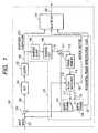
- a subtractor 102calculates the difference between the input image (current frame base image) 101 and the output image 113 (related later) of the interframe/intraframe coding selector 119, and then outputs an error image 103.
- This error imageis quantized in a quantizer 105 after being converted into DCT coefficients in a DCT converter 104 and then forms quantized DCT coefficients 106.
- quantized DCT coefficientsare transmitted through the communication channel while at the same time used to synthesize the interframe predicted image in the encoder.
- the procedure for synthesizing the predicted imageis explained next.
- the above mentioned quantized DCT coefficients 106forms the reconstructed error image 110 (same as the reconstructed error image on the receive side) after passing through a dequantizer 108 and inverse DCT converter 109.
- This reconstructed error image and the output image 113 of the interframe /intraframe coding selector 119is added at the adder 111 and the decoded image 112 of the current frame (same image as the decoded image of current frame reconstructed on the receiver side) is obtained.
- This imageis stored in a frame memory 114 and delayed for a time equal to the frame interval. Accordingly, at the current point, the frame memory 114 outputs the decoded image 115 of the previous frame.
- This decoded image of the previous frame and the original image 101 of the current frameare input to the block matching section 116 and block matching isperformed between these images.
- the block matching processthe original image of the current frame is segmented into multiple blocks, and the predicted image 117 of the current frame is synthesized by extracting the section most resembling these blocks from the decoded image of the previous frame. In this process, it is necessary to estimate the motion between the prior frame and the current frame for each block.
- the motion vector for each block estimated in the motion estimation processis transmitted to the receiver side as motion vector data 120.
- the same prediction image as on the transmitter sideis synthesized using the motion vector information and the decoding image of the previous frame.
- the prediction image 117is input along with a "0" signal 118 to the interframe /intraframe coding selector 119.
- This switch 119selects interframe coding or intraframe coding by selecting either of these inputs.
- Interframe codingis performed when the prediction image 117 is selected (this case is shown in Fig. 2).
- intraframe codingis performed since the input image itself is converted, to a DCT coefficients and output to the communication channel.
- an identifier flag 121is output to the communication circuit.
- an H.263 coded bitstream 123is acquired by multiplexing the quantized DCT coefficients, motion vectors, the and interframe/intraframe identifier flag information in a multiplexer 122.
- a decoder 200for receiving the coded bit stream output from the encoder of Fig. 1 is shown in Fig. 2.
- the H.263 coded bit stream 217 that is receivedis demultiplexed into quantized DCT coefficients 201, motion vector data 202, and a interframe/intraframe identifier flag 203 in the demultiplexer 216.
- the quantized DCT coefficients 201become a decoded error image 206 after being processed by an inverse quantizer 204 and inverse DCT converter 205.
- This decoded error imageis added to the output image 215 of the interframe /intraframe coding selector 214 in an adder 207 and the sum of these images is output as the decoded image 208.
- the output of the interframe /intraframe coding selectoris switched according to the interframe/intraframe identifier flag 203.
- a prediction image 212 utilized when performing interframe encodingis synthesized in the prediction image synthesizer 211. In this synthesizer, the position of the blocks in the decoded image 210 of the prior frame stored in frame memory 209 is shifted according to the motion vector data 202.
- the interframe /intraframe coding selectoroutputs the "0" signal 213 as is.
- the image encoded by H.263is comprised of a luminance plane (Y plane) containing luminance information, and two chrominance planes (U plane and V plane) containing chrominance information.
- Y planeluminance plane
- U plane and V planechrominance planes
- m and nare positive integers
- the Y planehas 2m pixels horizontally and 2n pixels vertically
- the U and V planeshave m pixels horizontally and n pixels vertically.
- the low resolution on the chrominance planeis due to the fact that the human visual system has a comparatively dull visual faculty with respect to spatial variations in chrominance.
- H. 263performs coding and decoding in block units referred to as macroblocks.
- the structure of a macroblockis shown in Fig. 3.
- the macroblockis comprised of three blocks; a Y block, U block and V block.
- the size of the Y block 301 containing the luminance informationis 16 X 16 pixels
- the size of the U block 302 and V block 303 containing the chrominance informationis 8 X 8 pixels.
- the intensity values for 401, 402, 403, 404are respectively La, Lb, Lc, and Ld (La, Lb, Lc, and Ld are non-negative integers)
- the interpolated intensity values Ia, Ib, Ic, and Id (Ia, Ib, Ic, and Id are non-negative integers) at positions405, 406, 407, 408are expressed by the following equation: where "[ ]" denotes truncation to the nearest integer towards 0 (i.e. the fractional part is discarded).
- the expectation of the errors caused by this rounding to integersis estimated as follows: It is assumed that the probability that the intensity value at positions 405, 406, 407, and 408 of Fig. 4 is used is all 25 percent.
- the number of pixelsis about half in both the vertical and horizontal direction on the chrominance plane. Therefore, for the motion vectors of the U block and V block, half the value of the motion vector for the Y block is used for the vertical and horizontal components. Since the horizontal and vertical components of the motion vector for the Y block motion vector are integral multiples of 1/2, the motion vector components for the U and V blocks will appear as integral multiples of 1/4 (quarter pixel accuracy) if ordinary division is implemented. However, due to the high computational complexity of the intensity interpolation process for motion vectors with quarter pixel accuracy, the motion vectors for U and V blocks are rounded to half pixel accuracy in H.263.
- the probability that the value of s prior to roundingis 0, 1, 2, and 3 are all 25 percent, the probability that s will be 0 or 2 after rounding will respectively be 25 percent and 75 percent.
- EP 0 712 249 Adiscloses a method and apparatus for interpolating pixel values in accordance with the first part of claim 1. This known system uses conventional fixed rounding. In EP 0 735 769 A an example of a bi-directional motion estimation method is disclosed also using fixed rounding. In the article " A motion compensation technique for down-scaled pictures in layered coding ", IEICE transactions on communications, Vol.77-B, No. 8, pages 1007-1012, August 1994 by Iwahashi et al. a method for reducing the dispersion of the reconstructed image based on Lagrange interpolation is proposed.
- Figure 1is a block diagram showing the layout of the H.263 image encoder.
- Figure 2is a block diagram showing the layout of the H.263 image decoder.
- Figure 3is a drawing showing the structure of the macro block.
- Figure 4is a drawing showing the interpolation process of intensity values for block matching with half pixel accuracy.
- Figure 5is a drawing showing a coded image sequence.
- Figure 6is a block diagram showing a software image encoding device.
- Figure 7is a block diagram showing a software image decoding device.
- Figure 8is a flow chart showing an example of processing in the software image encoding device.
- Figure 9is a flow chart showing an example of the coding mode decision processing for the software image encoding device.
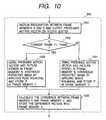
- Figure 10is a flow chart showing an example of motion estimation and motion compensation processing in the software image encoding device.
- Figure 11is a flow chart showing the processing in the software image decoding device.
- Figure 12is a flow chart showing an example of motion compensation processing in the software image decoding device.
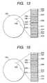
- Figure 13is a drawing showing an example of a storage media on which an encoded bit stream generated by an encoding method that outputs bit streams including I, P+ and P- frames is recorded.
- Figure 14is a set of drawings showing specific examples of devices using an encoding method where P+ and P- frames coexist.
- Figure 15is a drawing showing an example of a storage media on which an encoded bit stream generated by an encoding method the outputs bit streams including I, B, P+, and P-frames is recorded.
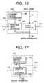
- Figure 16is a block diagram showing an example of a block matching unit included in a device using an encoding method where P+ and P- frames coexist.
- Figure 17is a block diagram showing the prediction image synthesizer included in a device for decoding bit streams encoded by an encoding method where P+ and P- frames coexist.
- An example of an image sequences encoded by coding methods which can perform both unidirectional prediction and bidirectional prediction such as in MPEG. 1, MPEG.2 and H.263is shown in Fig. 5.
- An image 501is a frame-coded by means of intraframe coding and is referred to as an I frame.
- images 503, 505, 507, 509are called P frames and are coded by unidirectional interframe coding by using the previous I or P frame as the reference image. Accordingly, when for instance encoding image 505, image 503 is used as the reference image and interframe prediction is performed.
- Images 502, 504, 506 and 508are called B frames and bidirectional interframe prediction is performed utilizing the previous and subsequent I or P frame.
- the B frameis characterized by not being used as a reference image when interframe prediction is performed. Since motion compensation is not performed in I frames, the rounding error caused by motion compensation will not occur. In contrast, not only is motion compensation performed in the P frames but the P frame is also used as a reference image by other P or B frames so that it may be a cause leading to accumulated rounding errors. In the B frames on the other hand, motion compensation is performed so that the effect of accumulated rounding errors appears in the reconstructed image. However, due to the fact that B frames are not used as reference images, B frames cannot be a source of accumulated rounding errors.
- a frame for coding a P frame and a B frameexists and is called a PB frame (For instance, frames 503 and 504 can both be encoded as a PB frame.) If the combined two frames are viewed as separate frames, then the same principle as above can be applied. In other words, if countermeasures are taken versus rounding errors for the P frame part within a PB frame, then the accumulation of errors can be prevented.
- Rounding errorsoccur during interpolation of intensity values when a value obtained from normal division (division whose operation result is a real number) is a half integer (0.5 added to an integer) and this result is then rounded up to the next integer in the direction away from zero. For instance, when dividing by 4 to find an interpolated intensity value is performed, the rounding errors for the cases when the residual is 1 and 3 have equal absolute values but different signs. Consequently, the rounding errors caused by these two cases are canceled when the expectation for the rounding errors is calculated (in more general words, when dividing by a positive integer d' is performed, the rounding errors caused by the cases when the residual is t and d' -t are cancelled).
- the two rounding methods used hereare: a rounding method that rounds half integers away from 0; and a rounding method that rounds half integers towards 0.
- the rounding errorscan be canceled.
- the rounding method that rounds the result of normal division to the nearest integer and rounds half integer values away from 0is called "positive rounding”.
- the rounding method that rounds the result of normal division to the nearest integer and rounds half integer values towards 0is called "negative rounding”.
- Equation 3When negative rounding is used instead, this equation can be rewritten as shown below.
- motion compensation methodsthat performs positive and negative rounding for the synthesis of interframe prediction images are called “motion compensation using positive rounding” and “motion compensation using negative rounding”, respectively.
- a frame that uses positive roundingis called a "P+ frame”
- a frame that uses negative roundingis called a "P- frame”
- the P frames in H. 263are all P+ frames.
- the expectation for the rounding errors in P+ and P- frameshave equal absolute values but different signs. Accordingly, the accumulation of rounding errors can be prevented when P+ frames and P- frames are alternately located along the time axis. In the example in Fig.
- the frames 503 and 507are set as P+ frames and the frames 505 and 509 are set as P- frames, then this method can be implemented.
- the alternate occurrence of P+ frames and P- framesleads to the usage of a P+ frame and a P- frame in the bidirectional prediction for B frames.
- the average of the forward prediction imagei.e. the prediction image synthesized by using frame 503 when frame 504 in Fig. 5 is being encoded
- the backward prediction imagei.e. the prediction image synthesized by using frame 505 when frame 504 in Fig. 5 is being encoded
- a block matching section 1600 of an image encoder according to the above described motion compensation method utilizing multiple rounding methodsis shown in Fig. 16. Numbers identical to those in other drawings indicate the same part. By substituting the block matching section 116 of Fig. 1 with 1600, multiple rounding methods can be used. Motion estimation processing between the input image 101 and the decoded image of the previous frame is performed in a motion estimator 1601. As a result, motion information 120 is output. This motion information is utilized in the synthesis of the prediction image in a prediction image synthesizer 1603. A rounding method determination device 1602 determines whether to use positive rounding or negative rounding as the rounding method for the frame currently being encoded. Information 1604 relating to the rounding method that was determined is input to the prediction image synthesizer 1603.
- a prediction image 117is synthesized and output based on the rounding method determined by means of information 1604.
- the rounding method 1605 determined at the block matching sectioncan be output, and this information can then be multiplexed into the bit stream and be transmitted.
- a prediction image synthesizer 1700 of an image decoder which can decode bit streams generated by a coding method using multiple rounding methodsis shown in Fig. 17. Numbers identical to those in other drawings indicate the same part. By substituting the prediction image synthesizer 211 of Fig. 2 by 1700, multiple rounding methods can be used. In the rounding method determination device 1701, the rounding method appropriate for prediction image synthesis in the decoding process is determined. In order to carry out decoding correctly, the rounding method selected here must be the same as the rounding method that was selected for encoding.
- the following rulecan be shared between the encoder and decoder: When the current frame is a P frame and the number of P frames (including the current frame) counted from the most recent I frame is odd, then the current frame is a P+ frame. When this number is even, then the current frame is a P- frame. If the rounding method determination device on the encoding side (For instance, 1602 in Fig. 16) and the rounding method determination device 1701 conform to this common rule, then the images can correctly be decoded.
- the prediction imageis synthesized in the prediction image synthesizer 1703 using motion information 202, decoding image 210 of the prior frame, and information 1702 related to the rounding method determined as just described.
- This prediction image 212is output and then used for the synthesis of the decoded image.
- a case where the information related to the rounding method is multiplexed in the transmitted bit streamcan also be considered (such bit stream can be generated at the encoder by outputting the information 1605 related to the rounding method from the block matching section depicted in Fig. 16).
- the rounding method determiner device 1701is not used, and information 1704 related to the rounding method extracted from the encoded bit stream is used at the prediction image synthesizer 1703.
- a software image encoder 600 and a software image decoder 700are shown in Fig. 6 and Fig. 7.
- the general-purpose processor 603loads information from here and performs encoding.
- the program for driving this general-purpose processoris loaded from a storage device 608 which can be a hard disk, floppy disk, etc. and stored in a program memory 604.
- This general-purpose processoralso uses a process memory 605 to perform the encoding.
- the encoding information output by the general-purpose processoris temporarily stored in the output buffer 606 and then output as an encoded bit stream 607.
- FIG. 8A flowchart for the encoding software (recording medium readable by computer) is shown in Fig. 8.
- the processstarts in 801, and the value 0 is assigned to variable N in 802.
- the value 0is assigned to N when the value for N is 100.
- Nis a counter for the number of frames. 1 is added for each one frame whose processing is complete, and values from 0 to 99 are allowed when performing coding.
- the current frameis an I frame.
- Nis an odd number
- the current frameis a P+ frame
- the current frameis a P- frame.
- NWhen the upper limit for the value of N is 99, it means that one I frame is coded after 99 P frames (P+ frames or P- frames) are coded. By always inserting one I frame in a certain number of coded frames, the following benefits can be obtained: (a) Error accumulation due to a mismatch between encoder and decoder processing can be prevented (for instance, a mismatch in the computation of DCT); and (b) The processing load for acquiring the reproduced image of the target frame from the coded data (-random access) is reduced.
- the optimal N valuevaries when the encoder performance or the environment where the encoder is used are changed. It does not mean, therefore, that the value of N must always be 100.
- the prediction imageis synthesized in 1004 utilizing negative rounding and this prediction image is stored in the frame memory C.
- the differential image between frame memories A and Cis found and stored in frame memory A.
- the processagain returns to Fig. 8.
- the input imageis stored in frame memory A when the current frame is an I frame, and the differential image between the input image and the prediction image is stored in frame memory A when the current frame is a P frame (P+ or P- frame).
- DCTis applied to the image stored in frame memory A, and the DCT coefficients calculated here are sent to the output buffer after being quantized.
- inverse quantizationis performed to the quantized DCT coefficients and inverse DCT is applied.
- the image obtained by applying inverse DCTis stored in frame memory B.
- 811it is checked again whether the current frame is an I frame. When the current frame is not an I frame, the images stored in frame memory B and C are added and the result is stored in frame memory B.
- the coding process of a frameends here, and the image stored in frame memory B before going into 813 is the reconstructed image of this frame (this image is identical with the one obtained at the decoding side).
- 813it is checked whether the frame whose coding has just finished is the final frame in the sequence. If this is true, the coding process ends. If this frame is not the final frame, 1 is added to N in 814, and the process again returns to 803 and the coding process for the next frame starts.
- a software decoder 700is shown in Fig. 7. After the coded bit stream 701 is temporarily stored in the input buffer 702, this bit stream is then loaded into the general-purpose processor 703.
- the program for driving this general-purpose processoris loaded from a storage device 708 which can be a hard disk, floppy disk, etc. and stored in a program memory 704.
- This general-purpose processoralso uses a process memory 605 to perform the decoding.
- the decoded image obtained by the decoding processis temporarily stored in the output frame memory 706 and then sent out as the output image 707.
- a flowchart of the decoding software for the software decoder 700 shown in Fig. 7is shown in Fig. 11.
- the processstarts in 1101, and it is checked in 1102 whether input information is present. If there is no input information, the decoding process ends in 1103.
- distinction information of the prediction modeis input in 1104.
- the word "input” used heremeans that the information stored in the input buffer (for instance 702 of Fig. 7) is loaded by the general-purposeprocessor.
- 1105it is checked whether the encoding mode distinction information is "I”. When not "I", the distinction information for the rounding method is input and synthesis of the interframe prediction image is performed in 1107.
- a flowchart showing details of the operation in 1107is shown in Fig. 12.
- a motion vectoris input for each block. Then, in 1202, it is checked whether the distinction information for the rounding method loaded in 1106 is a "+". When this information is "+", the frame currently being decoded is a P+ frame. In this case, the prediction image is synthesized using positive rounding in 1203, and the prediction image is stored in frame memory D.
- frame memory Dsignifies a portion of the memory zone of the software decoder (for instance, this memory zone is obtained in the processing memory 705 in Fig. 7).
- the distinction information of the rounding methodis not "+"
- the current frame being decodedis a P- frame.
- the prediction imageis synthesized using negative rounding in 1204 and this prediction image is stored in frame memory D.
- images stored in frame memory D and Eare added in 1110 and the resulting sum image is stored in frame memory E.
- the image stored in frame memory E before starting the process in 1111is the reconstructed image.
- This image stored in frame memory Eis output to the output frame memory (for instance, 706 in Fig. 7) in 1111, and then output from the decoder as the reconstructed image.
- the decoding process for a frameis completed here and the process for the next frame starts by returning to 1102.
- a storage media (recording media) with the bit stream generated by the software encoder 601 of Fig. 6 being recordedis shown in Fig. 13. It is assumed that the algorithms shown in the flowcharts of Figs. 8 - 10 is used in the software encoder.
- Digital informationis recorded concentrically on a recording disk 1301 capable of recording digital information (for instance magnetic disks, optical disk, etc.).
- a portion 1302 of the information recorded on this digital diskincludes: prediction mode distinction information 1303, 1305, 1308, 1311, and 1314; rounding method distinction information 1306, 1309, 1312, and 1315; and motion vector and DCT coefficient information 1304, 1307, 1310, 1313, and 1316.
- 'I'Information representing 'I' is recorded in 1303, 'P' is recorded in 1305, 1308, 1311, and 1314, '+' is recorded in 1306, and 1312, and '-' is recorded in 1309, and 1315.
- 'I' and '+'can be represented by a single bit of 0, and 'P' and '-' can be represented by a single bit of 1.
- the decodercan correctly interpret the recorded information and the correct reconstructed image is synthesized. By storing a coded bit stream in a storage media using the method described above, the accumulation of rounding errors is prevented when the bit stream is read and decoded.
- a storage media with the bit stream of the coded data of the image sequence shown in Fig. 5 being recordedis shown in Fig. 15.
- the recorded bit streamincludes information related to P+, P-, and B frames.
- digital informationis recorded concentrically on a record disk 1501 capable for recording digital information(for instance, magnetic disks, optical disks, etc.).
- a portion 1502 of the digital information recorded on this digital diskincludes: prediction mode distinction information 1503, 1505, 1508, 1510, and 1513; rounding method distinction information 1506, and 1512; and motion vector and DCT coefficient information 1504, 1507, 1509, 1511, and 1514.
- Information representing 'I'is recorded in 1503, 'P' is recorded in 1505, and 1510, 'B' is recorded in 1508, and 1513, '+' is recorded in 1505, and '-' is recorded in 1511.
- 'I', 'P' and 'B'can be represented respectively by two bit values 00, 01, and 10, and '+' and '-' can be represented respectively by one bit values 0 and 1.
- the decodercan correctly interpret the recorded information and the correct reconstructed is synthesized.
- the image coding and decoding methodcan be utilized by installing image coding and decoding software into a computer 1401. This software is recorded in some kind of storage media (CD-ROM, floppy disk, hard disk, etc.) 1412, loaded into a computer and then used. Additionally, the computer can be used as an image communication terminal by connecting the computer to a communication lines. It is also possible to install the decoding method described in this specification into a player device 1403 that reads and decodes the coded bit stream recorded in a storage media 1402. In this case, the reconstructed image signal can be displayed on a television monitor 1404.
- image coding and decoding methodcan be utilized by installing image coding and decoding software into a computer 1401. This software is recorded in some kind of storage media (CD-ROM, floppy disk, hard disk, etc.) 1412, loaded into a computer and then used. Additionally, the computer can be used as an image communication terminal by connecting the computer to a communication lines. It is also possible to install the decoding method described in this specification into a player device 14
- the device 1403can be used only for reading the coded bit stream, and in this case, the decoding device can be installed in the television monitor 1404. It is well known that digital data transmission can be realized using satellites and terrestrial waves. A decoding device can also be installed in a television receiver 1405 capable of receiving such digital transmissions. Also, a decoding device can also be installed inside a set top box 1409 connected to a satellite/terrestrial wave antenna, or a cable 1408 of a cable television system, so that the reconstructed images can be displayed on a television monitor 1410. In this case, the decoding device can be incorporated in the television monitor rather than in the set top box, as in the case of 1404. The layout of a digital satellite broadcast system is shown in 1413, 1414 and 1415.
- the video information in the coded bit streamis transmitted from a broadcast station 1413 to a communication or broadcast satellite 1414.
- the satellitereceives this information, sends it to a home 1415 having equipment for receiving satellite broadcast programs, and the video information is reconstructed and displayed in this home using devices such as a television receiver or a set top box.
- Digital image communication using mobile terminals 1406has recently attracted considerable attention, due to the fact that image communication at very low bit rates has become possible.
- Digital portable terminalscan be categorized in the following three types: a transceiver having both an encoder and decoder; a transmitter having only an encoder; and a receiver having only a decoder.
- An encoding devicecan be installed in a video camera recorder 1407.
- the cameracan also be used just for capturing the video signal and this signal can be supplied to a custom encoder 1411. All of the devices or systems shown in this drawing can be equipped with the coding or/and decoding method described in this specification. By using this coding or/and decoding method in these devices or systems, images of higher quality compared with those obtained using conventional technologies can be obtained.
Landscapes
- Engineering & Computer Science (AREA)
- Multimedia (AREA)
- Signal Processing (AREA)
- Physics & Mathematics (AREA)
- General Physics & Mathematics (AREA)
- Theoretical Computer Science (AREA)
- Discrete Mathematics (AREA)
- Computer Vision & Pattern Recognition (AREA)
- Mathematical Physics (AREA)
- Computing Systems (AREA)
- Compression Or Coding Systems Of Tv Signals (AREA)
- Compression, Expansion, Code Conversion, And Decoders (AREA)
- Studio Devices (AREA)
Description


Claims (12)
- A method for coding images comprising:characterised in thata step for storing a decoded image of a previous I frameor P frame as a reference image (112, 115);a step for performing motion compensation using an inputimage (101, 601) to be coded as a P frame and using saidreference image (115), by estimating motion vectors andsynthesizing a predicted image (117) of said input image(101, 601),
pixel value interpolation for obtaining said predictedimage (117) is performed by using positive rounding ornegative rounding, wherein said positive rounding rounds theresult of normal division to the nearest integer and roundshalf integer values away from 0 and said negative roundingrounds the result of normal division to the nearest integerand rounds half integer values towards 0; and by
a step for multiplexing in a bit stream (123, 607)comprising the coded image, information which identifieswhether the rounding method used for pixel valueinterpolation in said motion compensation is positiverounding or negative rounding. - The method for coding images of claim 1, wherein
said pixel value interpolation by using said positiverounding is calculated according to the equations
said pixel value interpolation by using said negativerounding is calculated according to the equations - The method for coding images of claim 1, wherein
a decoded image of said input image (101, 601) is usedas a reference image for the next input image which is codedas a P frame, and
the rounding method used in said motion compensation bysynthesizing said predicted image (117) is different fromthat used in motion compensation by synthesizing a predictedimage of said next input image. - The method for coding images of claim 1, wherein saidinformation is multiplexed in the bit stream (607) at theheader section (1306, 1309, 1312, 1315) of coded imageinformation.
- A computer readable medium for directing a computer toexecute an image coding method, said image coding method comprising:characterised in thata step for storing a decoded image of a previous I frameor P frame as a reference image (112, 115);a step for performing motion compensation using an inputimage (101, 601) to be coded as a P frame and using saidreference image (115), by estimating motion vectors andsynthesizing a predicted image (117) of said input image(101, 601),
pixel value interpolation for obtaining said predictedimage (117) is performed by using positive rounding ornegative rounding, wherein said positive rounding rounds theresult of normal division to the nearest integer and roundshalf integer values away from 0 and said negative roundingrounds the result of normal division to the nearest integerand rounds half integer values towards 0; and by
a step for multiplexing in a bit stream (123, 607)comprising the coded image, information which identifieswhether the rounding method used for pixel valueinterpolation in said motion compensation is positive rounding or negative rounding. - The computer readable medium of claim 5, wherein
said pixel value interpolation by using said positiverounding is calculated according to the equations
said pixel value interpolation by using said negativerounding is calculated according to the equations - The computer readable medium of claim 5, wherein
a decoded image of said input image (101, 601) is usedas a reference image for the next input image which is codedas a P frame, and
the rounding method used in said motion compensation bysynthesizing said predicted image (117) is different fromthat used in motion compensation by synthesizing a predictedimage of said next input image. - The computer readable medium of claim 5, wherein saidinformation is multiplexed in the bit stream (607) at theheader section (1306, 1309, 1312, 1315) of coded imageinformation.
- An encoder of images comprising:characterised bya memory for storing a decoded image of a previous Iframe or P frame as a reference image (115);a block matching section (116) for performing motioncompensation using an input image (101, 601) to be coded as aP frame and using said reference image (115), by estimatingmotion vectors and synthesizing a predicted image (117) ofsaid input image (101, 601),
a pixel value interpolation device for obtaining saidpredicted image (117) by using positive roundingor negative rounding, wherein said positive rounding roundsthe result of normal division to the nearest integer androunds half integer values away from 0 and said negativerounding rounds the result of normal division to the nearestinteger and rounds half integer values towards 0; and by
means for multiplexing in a bit stream (123, 607) comprising the coded image, information which identifieswhether the rounding method used for pixel valueinterpolation in said motion compensation is positiverounding or negative rounding. - The encoder of claim 9, wherein
said pixel value interpolation device is adapted to usesaid positive rounding which is calculated according to theequations
said pixel value interpolation device is adapted to usesaid negative rounding which is calculated according to theequations - The encoder of claim 9, wherein
an image device is adapted to use a decoded image ofsaid input image (101, 601) as a reference image for the nextinput image which is coded as a P frame, and
said block matching section is adapted to use therounding method in said motion compensation by synthesizingsaid predicted image (117) which is different from that usedin motion compensation by synthesizing a predicted image ofsaid next input image. - The encoder of claim 9, wherein
said multiplexing device multiplexes said information inthe bit stream (607) at the header section (1306, 1309, 1312,1315) of the coded image information.
Applications Claiming Priority (3)
| Application Number | Priority Date | Filing Date | Title |
|---|---|---|---|
| JP15065697 | 1997-06-09 | ||
| JP15065697 | 1997-06-09 | ||
| EP98110471AEP0884912B1 (en) | 1997-06-09 | 1998-06-08 | Image sequence decoding method |
Related Parent Applications (1)
| Application Number | Title | Priority Date | Filing Date |
|---|---|---|---|
| EP98110471.4Division | 1998-06-08 |
Publications (2)
| Publication Number | Publication Date |
|---|---|
| EP1056294A1 EP1056294A1 (en) | 2000-11-29 |
| EP1056294B1true EP1056294B1 (en) | 2002-10-02 |
Family
ID=15501626
Family Applications (11)
| Application Number | Title | Priority Date | Filing Date |
|---|---|---|---|
| EP10012307.4AExpired - LifetimeEP2288165B1 (en) | 1997-06-09 | 1998-06-08 | Image decoding method |
| EP98110471AExpired - LifetimeEP0884912B1 (en) | 1997-06-09 | 1998-06-08 | Image sequence decoding method |
| EP10012308.2AExpired - LifetimeEP2285119B1 (en) | 1997-06-09 | 1998-06-08 | Image decoding method |
| EP01129134AExpired - LifetimeEP1193977B1 (en) | 1997-06-09 | 1998-06-08 | Image sequence coding method |
| EP10012309.0AExpired - LifetimeEP2288166B1 (en) | 1997-06-09 | 1998-06-08 | Image decoding method |
| EP20020007746Expired - LifetimeEP1237377B1 (en) | 1997-06-09 | 1998-06-08 | Image decoding |
| EP00117806AExpired - LifetimeEP1056294B1 (en) | 1997-06-09 | 1998-06-08 | Image sequence coding method |
| EP02007745.9AExpired - LifetimeEP1237376B1 (en) | 1997-06-09 | 1998-06-08 | Image information recording medium |
| EP20100012305Expired - LifetimeEP2271116B1 (en) | 1997-06-09 | 1998-06-08 | Image decoding method and image decoder |
| EP20100012310Expired - LifetimeEP2271117B1 (en) | 1997-06-09 | 1998-06-08 | Image decoding method and image decoder |
| EP20100012306Expired - LifetimeEP2288164B1 (en) | 1997-06-09 | 1998-06-08 | Image decoding method and image decoder |
Family Applications Before (6)
| Application Number | Title | Priority Date | Filing Date |
|---|---|---|---|
| EP10012307.4AExpired - LifetimeEP2288165B1 (en) | 1997-06-09 | 1998-06-08 | Image decoding method |
| EP98110471AExpired - LifetimeEP0884912B1 (en) | 1997-06-09 | 1998-06-08 | Image sequence decoding method |
| EP10012308.2AExpired - LifetimeEP2285119B1 (en) | 1997-06-09 | 1998-06-08 | Image decoding method |
| EP01129134AExpired - LifetimeEP1193977B1 (en) | 1997-06-09 | 1998-06-08 | Image sequence coding method |
| EP10012309.0AExpired - LifetimeEP2288166B1 (en) | 1997-06-09 | 1998-06-08 | Image decoding method |
| EP20020007746Expired - LifetimeEP1237377B1 (en) | 1997-06-09 | 1998-06-08 | Image decoding |
Family Applications After (4)
| Application Number | Title | Priority Date | Filing Date |
|---|---|---|---|
| EP02007745.9AExpired - LifetimeEP1237376B1 (en) | 1997-06-09 | 1998-06-08 | Image information recording medium |
| EP20100012305Expired - LifetimeEP2271116B1 (en) | 1997-06-09 | 1998-06-08 | Image decoding method and image decoder |
| EP20100012310Expired - LifetimeEP2271117B1 (en) | 1997-06-09 | 1998-06-08 | Image decoding method and image decoder |
| EP20100012306Expired - LifetimeEP2288164B1 (en) | 1997-06-09 | 1998-06-08 | Image decoding method and image decoder |
Country Status (9)
| Country | Link |
|---|---|
| US (92) | US6295376B1 (en) |
| EP (11) | EP2288165B1 (en) |
| JP (17) | JP3092610B2 (en) |
| KR (4) | KR100393123B1 (en) |
| CN (8) | CN100415000C (en) |
| CA (1) | CA2240118C (en) |
| DE (2) | DE69808519T2 (en) |
| ES (10) | ES2545089T3 (en) |
| TW (2) | TW411698B (en) |
Families Citing this family (155)
| Publication number | Priority date | Publication date | Assignee | Title |
|---|---|---|---|---|
| JP2613044B2 (en) | 1987-02-25 | 1997-05-21 | 横浜ゴム株式会社 | Pneumatic radial tire |
| AU1941797A (en)* | 1997-03-17 | 1998-10-12 | Mitsubishi Denki Kabushiki Kaisha | Image encoder, image decoder, image encoding method, image decoding method and image encoding/decoding system |
| US6574371B2 (en)* | 1997-06-09 | 2003-06-03 | Hitachi, Ltd. | Image decoding method |
| CA2240118C (en)* | 1997-06-09 | 2005-11-22 | Hitachi Ltd. | Image sequence coding method and decoding method |
| US7801380B2 (en)* | 1997-06-09 | 2010-09-21 | Hitachi, Ltd. | Recording medium having recorded thereon coded information using plus and/or minus rounding of images |
| JP3410037B2 (en) | 1997-06-09 | 2003-05-26 | 株式会社日立製作所 | Decoding method, decoding device, and computer-readable recording medium |
| JP3407726B2 (en) | 1997-06-09 | 2003-05-19 | 株式会社日立製作所 | Encoding method, encoding device, and computer-readable recording medium |
| KR100282147B1 (en)* | 1998-11-13 | 2001-02-15 | 구자홍 | Compressed Image Restoration Method |
| US6983018B1 (en) | 1998-11-30 | 2006-01-03 | Microsoft Corporation | Efficient motion vector coding for video compression |
| CN1293782A (en)* | 1999-02-01 | 2001-05-02 | 皇家菲利浦电子有限公司 | Descriptor for video sequence and image retrieval system using said descriptor |
| JP2000270330A (en)* | 1999-03-18 | 2000-09-29 | Fujitsu Ltd | Video distribution system and video distribution method |
| US6567557B1 (en)* | 1999-12-10 | 2003-05-20 | Stmicroelectronics, Inc. | Method for preventing dual-step half-pixel motion compensation accumulation errors in prediction-rich MPEG-2 sequences |
| EP1090502B1 (en)* | 1999-04-26 | 2005-11-30 | Koninklijke Philips Electronics N.V. | Sub-pixel accurate motion vector estimation and motion-compensated interpolation |
| US7170941B2 (en)* | 1999-08-13 | 2007-01-30 | Patapsco Designs Inc. | Temporal compression |
| JP4129664B2 (en)* | 1999-10-05 | 2008-08-06 | ソニー株式会社 | Data processing apparatus and data processing method |
| US6683986B1 (en)* | 1999-10-28 | 2004-01-27 | Sharp Laboratories Of America, Inc. | Efficient transmission of quarter-VGA images using DVC codecs |
| WO2001058169A1 (en)* | 2000-02-04 | 2001-08-09 | Koninklijke Philips Electronics N.V. | Method of reducing blocking artifacts |
| US6512523B1 (en)* | 2000-03-27 | 2003-01-28 | Intel Corporation | Accurate averaging of elements using integer averaging |
| JP2003534743A (en)* | 2000-05-19 | 2003-11-18 | コーニンクレッカ フィリップス エレクトロニクス エヌ ヴィ | Methods, systems and devices |
| US7168069B1 (en)* | 2000-07-12 | 2007-01-23 | Stmicroelectronics, Inc. | Dynamic generation of multimedia code for image processing |
| DE60144176D1 (en)* | 2000-11-10 | 2011-04-21 | Ricoh Co Ltd | Image decompression of transform coefficients |
| KR100386639B1 (en)* | 2000-12-04 | 2003-06-02 | 주식회사 오픈비주얼 | Method for decompression of images and video using regularized dequantizer |
| US7054500B1 (en)* | 2000-12-06 | 2006-05-30 | Realnetworks, Inc. | Video compression and decompression system with postfilter to filter coding artifacts |
| US7170997B2 (en) | 2000-12-07 | 2007-01-30 | Cryptico A/S | Method of generating pseudo-random numbers in an electronic device, and a method of encrypting and decrypting electronic data |
| US6898245B2 (en) | 2001-03-26 | 2005-05-24 | Telefonaktiebolaget Lm Ericsson (Publ) | Low complexity video decoding |
| US7266150B2 (en)* | 2001-07-11 | 2007-09-04 | Dolby Laboratories, Inc. | Interpolation of video compression frames |
| EP2096871B1 (en)* | 2001-09-14 | 2014-11-12 | NTT DoCoMo, Inc. | Coding method, decoding method, coding apparatus, decoding apparatus, image processing system, coding program, and decoding program |
| CN1298171C (en)* | 2001-09-18 | 2007-01-31 | 松下电器产业株式会社 | Image encoding method and image decoding method |
| JP3932379B2 (en)* | 2001-10-02 | 2007-06-20 | 株式会社日立製作所 | Image processing apparatus and image sensor |
| CN101448162B (en)* | 2001-12-17 | 2013-01-02 | 微软公司 | Method for processing video image |
| EP1827026A1 (en)* | 2002-01-18 | 2007-08-29 | Kabushiki Kaisha Toshiba | Video decoding method and apparatus |
| JP3861698B2 (en) | 2002-01-23 | 2006-12-20 | ソニー株式会社 | Image information encoding apparatus and method, image information decoding apparatus and method, and program |
| US7003035B2 (en) | 2002-01-25 | 2006-02-21 | Microsoft Corporation | Video coding methods and apparatuses |
| US7266254B2 (en) | 2002-02-13 | 2007-09-04 | Canon Kabushiki Kaisha | Data processing apparatus, image processing apparatus, and method therefor |
| US8284844B2 (en) | 2002-04-01 | 2012-10-09 | Broadcom Corporation | Video decoding system supporting multiple standards |
| US7116831B2 (en)* | 2002-04-10 | 2006-10-03 | Microsoft Corporation | Chrominance motion vector rounding |
| US7110459B2 (en) | 2002-04-10 | 2006-09-19 | Microsoft Corporation | Approximate bicubic filter |
| US7305034B2 (en)* | 2002-04-10 | 2007-12-04 | Microsoft Corporation | Rounding control for multi-stage interpolation |
| US7620109B2 (en)* | 2002-04-10 | 2009-11-17 | Microsoft Corporation | Sub-pixel interpolation in motion estimation and compensation |
| US20040001546A1 (en) | 2002-06-03 | 2004-01-01 | Alexandros Tourapis | Spatiotemporal prediction for bidirectionally predictive (B) pictures and motion vector prediction for multi-picture reference motion compensation |
| US20040086117A1 (en)* | 2002-06-06 | 2004-05-06 | Petersen Mette Vesterager | Methods for improving unpredictability of output of pseudo-random number generators |
| US7224731B2 (en) | 2002-06-28 | 2007-05-29 | Microsoft Corporation | Motion estimation/compensation for screen capture video |
| US7280700B2 (en) | 2002-07-05 | 2007-10-09 | Microsoft Corporation | Optimization techniques for data compression |
| JP4724351B2 (en) | 2002-07-15 | 2011-07-13 | 三菱電機株式会社 | Image encoding apparatus, image encoding method, image decoding apparatus, image decoding method, and communication apparatus |
| JP4078906B2 (en)* | 2002-07-19 | 2008-04-23 | ソニー株式会社 | Image signal processing apparatus and processing method, image display apparatus, coefficient data generating apparatus and generating method used therefor, program for executing each method, and computer-readable medium storing the program |
| US7154952B2 (en) | 2002-07-19 | 2006-12-26 | Microsoft Corporation | Timestamp-independent motion vector prediction for predictive (P) and bidirectionally predictive (B) pictures |
| KR100472476B1 (en)* | 2002-08-31 | 2005-03-10 | 삼성전자주식회사 | Interpolation apparatus and method for moving vector compensation |
| EP1566970A4 (en) | 2002-11-20 | 2008-12-03 | Panasonic Corp | ANIMATED IMAGE PREDICTION METHOD, ANIMATED IMAGE ENCODING METHOD AND DEVICE, AND ANIMATED IMAGE DECODING METHOD AND DEVICE |
| US7403660B2 (en)* | 2003-04-30 | 2008-07-22 | Nokia Corporation | Encoding picture arrangement parameter in picture bitstream |
| US20040252762A1 (en)* | 2003-06-16 | 2004-12-16 | Pai R. Lakshmikanth | System, method, and apparatus for reducing memory and bandwidth requirements in decoder system |
| US7499495B2 (en) | 2003-07-18 | 2009-03-03 | Microsoft Corporation | Extended range motion vectors |
| US7426308B2 (en) | 2003-07-18 | 2008-09-16 | Microsoft Corporation | Intraframe and interframe interlace coding and decoding |
| US7609763B2 (en) | 2003-07-18 | 2009-10-27 | Microsoft Corporation | Advanced bi-directional predictive coding of video frames |
| US10554985B2 (en) | 2003-07-18 | 2020-02-04 | Microsoft Technology Licensing, Llc | DC coefficient signaling at small quantization step sizes |
| US20050013498A1 (en)* | 2003-07-18 | 2005-01-20 | Microsoft Corporation | Coding of motion vector information |
| US7738554B2 (en) | 2003-07-18 | 2010-06-15 | Microsoft Corporation | DC coefficient signaling at small quantization step sizes |
| US8064520B2 (en)* | 2003-09-07 | 2011-11-22 | Microsoft Corporation | Advanced bi-directional predictive coding of interlaced video |
| US7577200B2 (en) | 2003-09-07 | 2009-08-18 | Microsoft Corporation | Extended range variable length coding/decoding of differential motion vector information |
| US7724827B2 (en) | 2003-09-07 | 2010-05-25 | Microsoft Corporation | Multi-layer run level encoding and decoding |
| US7599438B2 (en) | 2003-09-07 | 2009-10-06 | Microsoft Corporation | Motion vector block pattern coding and decoding |
| US7567617B2 (en) | 2003-09-07 | 2009-07-28 | Microsoft Corporation | Predicting motion vectors for fields of forward-predicted interlaced video frames |
| US7623574B2 (en) | 2003-09-07 | 2009-11-24 | Microsoft Corporation | Selecting between dominant and non-dominant motion vector predictor polarities |
| US7616692B2 (en) | 2003-09-07 | 2009-11-10 | Microsoft Corporation | Hybrid motion vector prediction for interlaced forward-predicted fields |
| US7317839B2 (en) | 2003-09-07 | 2008-01-08 | Microsoft Corporation | Chroma motion vector derivation for interlaced forward-predicted fields |
| US7620106B2 (en) | 2003-09-07 | 2009-11-17 | Microsoft Corporation | Joint coding and decoding of a reference field selection and differential motion vector information |
| US20050105621A1 (en) | 2003-11-04 | 2005-05-19 | Ju Chi-Cheng | Apparatus capable of performing both block-matching motion compensation and global motion compensation and method thereof |
| NO319629B1 (en)* | 2003-11-28 | 2005-09-05 | Tandberg Telecom As | Procedure for correcting interpolated pixel values |
| KR100601935B1 (en)* | 2003-12-02 | 2006-07-14 | 삼성전자주식회사 | Digital video processing method and device |
| FI20035235A0 (en)* | 2003-12-12 | 2003-12-12 | Nokia Corp | Arrangement for processing files at a terminal |
| US7643182B2 (en)* | 2003-12-16 | 2010-01-05 | Seiko Epson Corporation | System and method for processing image data |
| JP2005184632A (en)* | 2003-12-22 | 2005-07-07 | Nec Access Technica Ltd | Power consumption reduction method in communication terminal, and communication terminal |
| KR20070033343A (en)* | 2004-07-13 | 2007-03-26 | 돌비 레버러토리즈 라이쎈싱 코오포레이션 | Unbiased rounding for video compression |
| US7548259B2 (en)* | 2004-08-12 | 2009-06-16 | Microsoft Corporation | System and method for producing a higher resolution still image from video information |
| WO2006028088A1 (en) | 2004-09-08 | 2006-03-16 | Matsushita Electric Industrial Co., Ltd. | Motion image encoding method and motion image decoding method |
| US7941177B2 (en) | 2004-09-15 | 2011-05-10 | Samsung Electronics Co., Ltd | Wireless terminal apparatus for automatically changing WLAN standard and method thereof |
| JP2006190259A (en)* | 2004-12-06 | 2006-07-20 | Canon Inc | Camera shake determination apparatus, image processing apparatus, control method thereof, and program |
| KR100634531B1 (en)* | 2004-12-29 | 2006-10-16 | 삼성전자주식회사 | Dynamic capacitance compensation device and method of liquid crystal display |
| US7634148B2 (en)* | 2005-01-07 | 2009-12-15 | Ntt Docomo, Inc. | Image signal transforming and inverse-transforming method and computer program product with pre-encoding filtering features |
| US7953283B2 (en)* | 2005-01-27 | 2011-05-31 | Panasonic Corporation | Portable terminal |
| JP2006217406A (en)* | 2005-02-04 | 2006-08-17 | Sony Corp | Coding apparatus and method, decoding apparatus and method, recording medium, program, and image processing system and method |
| CN101194513B (en)* | 2005-06-10 | 2011-07-20 | Nxp股份有限公司 | up and down motion vector |
| EP1922898A1 (en)* | 2005-09-09 | 2008-05-21 | Yamaha Corporation | Capacitor microphone |
| US8208553B2 (en)* | 2006-05-04 | 2012-06-26 | Altera Corporation | Methods and apparatus for quarter-pel refinement in a SIMD array processor |
| US8194760B2 (en)* | 2006-06-01 | 2012-06-05 | Ntt Docomo, Inc. | Method and apparatus for distributed space-time coding in wireless radio networks |
| KR100885693B1 (en)* | 2006-06-14 | 2009-02-26 | 한국전자통신연구원 | Video encoding apparatus and method using signal separation algorithm based on independent component analysis, video decoding apparatus and method using same |
| US20080039166A1 (en)* | 2006-08-03 | 2008-02-14 | Seven Lights, Llc | Systems and methods for multi-character online gaming |
| US20080039169A1 (en)* | 2006-08-03 | 2008-02-14 | Seven Lights, Llc | Systems and methods for character development in online gaming |
| US20080039165A1 (en)* | 2006-08-03 | 2008-02-14 | Seven Lights, Llc | Systems and methods for a scouting report in online gaming |
| US8194744B2 (en)* | 2006-09-20 | 2012-06-05 | Lsi Corporation | Method and/or apparatus for implementing reduced bandwidth high performance VC1 intensity compensation |
| US20100134631A1 (en)* | 2006-10-30 | 2010-06-03 | Wesleyan University | Apparatus and method for real time image compression for particle tracking |
| US8861356B2 (en)* | 2007-03-13 | 2014-10-14 | Ntt Docomo, Inc. | Method and apparatus for prioritized information delivery with network coding over time-varying network topologies |
| WO2008122956A2 (en)* | 2007-04-09 | 2008-10-16 | Nokia Corporation | High accuracy motion vectors for video coding with low encoder and decoder complexity |
| US8254455B2 (en) | 2007-06-30 | 2012-08-28 | Microsoft Corporation | Computing collocated macroblock information for direct mode macroblocks |
| JP2009077383A (en)* | 2007-08-27 | 2009-04-09 | Sony Corp | Image processing apparatus and method, and program |
| US8605786B2 (en)* | 2007-09-04 | 2013-12-10 | The Regents Of The University Of California | Hierarchical motion vector processing method, software and devices |
| US20090075686A1 (en)* | 2007-09-19 | 2009-03-19 | Gomadam Krishna S | Method and apparatus for wideband transmission based on multi-user mimo and two-way training |
| US8325840B2 (en)* | 2008-02-25 | 2012-12-04 | Ntt Docomo, Inc. | Tree position adaptive soft output M-algorithm receiver structures |
| US8279954B2 (en)* | 2008-03-06 | 2012-10-02 | Ntt Docomo, Inc. | Adaptive forward-backward soft output M-algorithm receiver structures |
| US20090262249A1 (en)* | 2008-04-22 | 2009-10-22 | Himax Media Solutions, Inc. | Interpolated frame generating method |
| CN101345872B (en)* | 2008-05-23 | 2010-06-09 | 清华大学 | A Method of Realizing Bilinear Interpolation in Video Codec |
| US8565329B2 (en)* | 2008-06-03 | 2013-10-22 | Ntt Docomo, Inc. | Soft output M-algorithm receiver structures with generalized survivor selection criteria for MIMO systems |
| JPWO2010001832A1 (en)* | 2008-06-30 | 2011-12-22 | 株式会社東芝 | Moving picture predictive coding apparatus and moving picture predictive decoding apparatus |
| BRPI0915971A2 (en)* | 2008-07-25 | 2019-02-26 | Sony Corp | device and image processing method |
| JP4444354B2 (en)* | 2008-08-04 | 2010-03-31 | 株式会社東芝 | Image processing apparatus and image processing method |
| US8229443B2 (en)* | 2008-08-13 | 2012-07-24 | Ntt Docomo, Inc. | Method of combined user and coordination pattern scheduling over varying antenna and base-station coordination patterns in a multi-cell environment |
| US8451951B2 (en)* | 2008-08-15 | 2013-05-28 | Ntt Docomo, Inc. | Channel classification and rate adaptation for SU-MIMO systems |
| US8705484B2 (en)* | 2008-08-15 | 2014-04-22 | Ntt Docomo, Inc. | Method for varying transmit power patterns in a multi-cell environment |
| US8542640B2 (en)* | 2008-08-28 | 2013-09-24 | Ntt Docomo, Inc. | Inter-cell approach to operating wireless beam-forming and user selection/scheduling in multi-cell environments based on limited signaling between patterns of subsets of cells |
| US8855221B2 (en)* | 2008-09-15 | 2014-10-07 | Ntt Docomo, Inc. | Method and apparatus for iterative receiver structures for OFDM/MIMO systems with bit interleaved coded modulation |
| JP5143038B2 (en)* | 2009-02-02 | 2013-02-13 | オリンパス株式会社 | Image processing apparatus and image processing method |
| US8189666B2 (en) | 2009-02-02 | 2012-05-29 | Microsoft Corporation | Local picture identifier and computation of co-located information |
| JP2010258739A (en)* | 2009-04-24 | 2010-11-11 | Sony Corp | Image processing apparatus, method and program |
| US9048977B2 (en)* | 2009-05-05 | 2015-06-02 | Ntt Docomo, Inc. | Receiver terminal driven joint encoder and decoder mode adaptation for SU-MIMO systems |
| JP5291804B2 (en) | 2009-11-17 | 2013-09-18 | シャープ株式会社 | Encoding apparatus, control method of encoding apparatus, transmission system, and computer-readable recording medium recording control program |
| US8824825B2 (en)* | 2009-11-17 | 2014-09-02 | Sharp Kabushiki Kaisha | Decoding device with nonlinear process section, control method for the decoding device, transmission system, and computer-readable recording medium having a control program recorded thereon |
| US20110200108A1 (en)* | 2010-02-18 | 2011-08-18 | Qualcomm Incorporated | Chrominance high precision motion filtering for motion interpolation |
| EP2555523A4 (en)* | 2010-03-31 | 2016-05-11 | Mitsubishi Electric Corp | IMAGE ENCRYPTION DEVICE, IMAGE KEYING DEVICE, IMAGE ENCRYPTION METHOD AND IMAGE KEYING PROCESS |
| JP5390458B2 (en)* | 2010-04-08 | 2014-01-15 | 株式会社Nttドコモ | Moving picture predictive coding apparatus, moving picture predictive coding method, moving picture predictive coding program, moving picture predictive decoding apparatus, moving picture predictive decoding method, and moving picture predictive decoding program |
| DK2558577T3 (en) | 2010-04-16 | 2019-04-01 | Nuevolution As | Bi-functional complexes and methods for the preparation and use of such complexes |
| CN101917624B (en)* | 2010-07-26 | 2013-04-03 | 清华大学 | Method for reconstructing high resolution video image |
| US8968080B1 (en)* | 2010-11-05 | 2015-03-03 | Wms Gaming, Inc. | Display of third party content on a wagering game machine |
| JP5768491B2 (en)* | 2011-05-17 | 2015-08-26 | ソニー株式会社 | Image processing apparatus and method, program, and recording medium |
| US9965358B2 (en) | 2011-05-27 | 2018-05-08 | Empire Technology Development Llc | Seamless application backup and recovery using metadata |
| US8805099B2 (en)* | 2011-06-22 | 2014-08-12 | Panasonic Intellectual Property Corporation Of America | Image decoding method and image coding method |
| JP2013102297A (en) | 2011-11-07 | 2013-05-23 | Canon Inc | Image encoding method, image encoder and program, image decoding method, and image decoder and program |
| JP5871628B2 (en)* | 2011-11-07 | 2016-03-01 | キヤノン株式会社 | Image encoding device, image encoding method and program, image decoding device, image decoding method and program |
| US10410020B2 (en)* | 2011-12-23 | 2019-09-10 | Knauf Gips Kg | Method and system for checking the presence and/or readability of an item of product information |
| EP3406433A1 (en) | 2012-01-23 | 2018-11-28 | Apio, Inc. | Atmosphere control around respiring biological materials |
| KR101691314B1 (en)* | 2012-06-11 | 2016-12-29 | 닛폰 호소 교카이 | Encoding device, decoding device, and program |
| AU2013281946B2 (en) | 2012-06-29 | 2017-03-02 | Sony Group Corporation | Decoding device, and decoding method |
| WO2014049667A1 (en)* | 2012-09-28 | 2014-04-03 | 株式会社島津製作所 | Digital image processing method and imaging device |
| CN104104960B (en) | 2013-04-03 | 2017-06-27 | 华为技术有限公司 | Multi-level two-way motion estimation method and device |
| US10303658B2 (en)* | 2013-11-25 | 2019-05-28 | Dropbox, Inc. | Generating and sharing metadata for indexing synchronized content items |
| EP4057203A1 (en)* | 2013-12-19 | 2022-09-14 | Visa International Service Association | Cloud-based transactions methods and systems |
| US9304657B2 (en)* | 2013-12-31 | 2016-04-05 | Abbyy Development Llc | Audio tagging |
| US9942560B2 (en) | 2014-01-08 | 2018-04-10 | Microsoft Technology Licensing, Llc | Encoding screen capture data |
| US9749642B2 (en) | 2014-01-08 | 2017-08-29 | Microsoft Technology Licensing, Llc | Selection of motion vector precision |
| US9774881B2 (en) | 2014-01-08 | 2017-09-26 | Microsoft Technology Licensing, Llc | Representing motion vectors in an encoded bitstream |
| US20150200156A1 (en)* | 2014-01-13 | 2015-07-16 | Altera Corporation | Module having mirror-symmetric terminals and methods of forming the same |
| US9147262B1 (en) | 2014-08-25 | 2015-09-29 | Xerox Corporation | Methods and systems for image processing |
| US10387596B2 (en)* | 2014-08-26 | 2019-08-20 | International Business Machines Corporation | Multi-dimension variable predictive modeling for yield analysis acceleration |
| SG11201702743WA (en)* | 2014-10-03 | 2017-06-29 | Nec Corp | Video coding device, video decoding device, video coding method, video decoding method and program |
| CN105611182B (en)* | 2014-11-25 | 2020-05-22 | 中兴通讯股份有限公司 | Brightness compensation method and device |
| KR102349788B1 (en) | 2015-01-13 | 2022-01-11 | 인텔렉추얼디스커버리 주식회사 | Method and apparatus for encoding/decoding video |
| US10595021B2 (en)* | 2015-03-13 | 2020-03-17 | Sony Corporation | Image processing device and method |
| US9955802B2 (en) | 2015-04-08 | 2018-05-01 | Fasteners For Retail, Inc. | Divider with selectively securable track assembly |
| WO2017031671A1 (en)* | 2015-08-24 | 2017-03-02 | 华为技术有限公司 | Motion vector field coding method and decoding method, and coding and decoding apparatuses |
| KR102476148B1 (en) | 2016-12-28 | 2022-12-12 | 소니그룹주식회사 | Image processing apparatus and method |
| US10509601B2 (en)* | 2016-12-28 | 2019-12-17 | Amazon Technologies, Inc. | Data storage system with multi-tier control plane |
| US10570759B2 (en)* | 2017-07-10 | 2020-02-25 | GM Global Technology Operations LLC | Variable-geometry turbine housing intake channel for an exhaust driven turbocharger |
| JP7241197B2 (en)* | 2019-03-18 | 2023-03-16 | テンセント・アメリカ・エルエルシー | Method and apparatus for video coding |
| CN112583878B (en)* | 2019-09-30 | 2023-03-14 | 阿波罗智能技术(北京)有限公司 | Vehicle information checking method, device, equipment and medium |
| CN112203094B (en)* | 2020-11-16 | 2024-05-14 | 北京世纪好未来教育科技有限公司 | Encoding method, encoding device, electronic equipment and storage medium |
| CN115299048A (en)* | 2021-01-20 | 2022-11-04 | 京东方科技集团股份有限公司 | Image coding method, image decoding method, image coding device, image decoding device, image coding and decoding device and codec |
| CN116760988B (en)* | 2023-08-18 | 2023-11-10 | 瀚博半导体(上海)有限公司 | Video coding method and device based on human visual system |
Family Cites Families (44)
| Publication number | Priority date | Publication date | Assignee | Title |
|---|---|---|---|---|
| GB1341375A (en) | 1969-11-19 | 1973-12-19 | Smith Kline French Lab | Aminoalkylimidazoles and process for their production |
| JPS6214754A (en) | 1985-07-13 | 1987-01-23 | Junichi Sugawara | Preservation treatment of cooked rice and product thereof |
| JPS62147654A (en) | 1985-12-23 | 1987-07-01 | Showa Denko Kk | Method for manufacturing lithium-aluminum alloy electrode |
| FR2620502B1 (en) | 1987-09-10 | 1989-12-08 | Valeo | TORSION DAMPING DEVICE |
| US5054103A (en) | 1987-09-24 | 1991-10-01 | Matsushita Electric Works, Ltd. | Picture encoding system |
| US5379351A (en)* | 1992-02-19 | 1995-01-03 | Integrated Information Technology, Inc. | Video compression/decompression processing and processors |
| JP2749700B2 (en) | 1990-04-18 | 1998-05-13 | 三菱電機株式会社 | Linear image sensor |
| JP2827461B2 (en) | 1990-06-18 | 1998-11-25 | 株式会社デンソー | Electronic refrigerator |
| JPH06214754A (en) | 1993-01-14 | 1994-08-05 | Toshiba Corp | Rounding operation circuit and image processing apparatus having the same |
| US5737022A (en)* | 1993-02-26 | 1998-04-07 | Kabushiki Kaisha Toshiba | Motion picture error concealment using simplified motion compensation |
| TW224553B (en)* | 1993-03-01 | 1994-06-01 | Sony Co Ltd | Method and apparatus for inverse discrete consine transform and coding/decoding of moving picture |
| US5486876A (en) | 1993-04-27 | 1996-01-23 | Array Microsystems, Inc. | Video interface unit for mapping physical image data to logical tiles |
| EP0671816B1 (en)* | 1993-09-28 | 2000-03-29 | Sony Corporation | Encoding/decoding device with all odd or all even value rounding |
| JPH07153195A (en)* | 1993-11-30 | 1995-06-16 | Sony Corp | Digital recording device |
| GB9402807D0 (en) | 1994-02-14 | 1994-04-06 | Xenova Ltd | Pharmaceutical compounds |
| US5685963A (en)* | 1994-10-31 | 1997-11-11 | Saes Pure Gas, Inc. | In situ getter pump system and method |
| US5638128A (en)* | 1994-11-08 | 1997-06-10 | General Instrument Corporation Of Delaware | Pixel interpolation filters for video decompression processor |
| JP3191583B2 (en)* | 1994-12-12 | 2001-07-23 | ソニー株式会社 | Information decryption device |
| JP3623967B2 (en)* | 1995-03-08 | 2005-02-23 | 株式会社 日立製作所 | Portable multimedia communication terminal device |
| US5650823A (en)* | 1995-03-27 | 1997-07-22 | International Business Machines Corporation | Half pel motion estimation method for B pictures |
| GB2301972B (en)* | 1995-06-06 | 1999-10-20 | Sony Uk Ltd | Video compression |
| JP3081507B2 (en) | 1995-06-15 | 2000-08-28 | 三菱電機ビルテクノサービス株式会社 | Curing sheet storage device in basket |
| US5740283A (en)* | 1995-07-06 | 1998-04-14 | Rubin, Bednarek & Associates, Inc. | Digital video compression utilizing mixed vector and scalar outputs |
| JP3700230B2 (en) | 1996-01-12 | 2005-09-28 | 株式会社日立製作所 | Motion compensation method in video coding |
| JP3183155B2 (en) | 1996-03-18 | 2001-07-03 | 株式会社日立製作所 | Image decoding apparatus and image decoding method |
| JPH1098729A (en) | 1996-09-20 | 1998-04-14 | Hitachi Ltd | Method of synthesizing inter-frame prediction image |
| US6205178B1 (en)* | 1996-09-20 | 2001-03-20 | Hitachi, Ltd. | Method and synthesizing a predicted image, video coding device and video coding method |
| US5740263A (en)* | 1996-10-23 | 1998-04-14 | Liao; Lu-Lee | Multi-media microphone seat |
| US6058410A (en) | 1996-12-02 | 2000-05-02 | Intel Corporation | Method and apparatus for selecting a rounding mode for a numeric operation |
| US5905542A (en)* | 1996-12-04 | 1999-05-18 | C-Cube Microsystems, Inc. | Simplified dual prime video motion estimation |
| US6056410A (en)* | 1997-04-02 | 2000-05-02 | Donnelly Corporation | Digital electrochromic mirror system |
| US5837022A (en)* | 1997-05-19 | 1998-11-17 | Chapman; Rick L. | High efficiency air filter system |
| JP2998741B2 (en)* | 1997-06-09 | 2000-01-11 | 株式会社日立製作所 | Moving picture encoding method, computer-readable recording medium on which the method is recorded, and moving picture encoding apparatus |
| US6574371B2 (en)* | 1997-06-09 | 2003-06-03 | Hitachi, Ltd. | Image decoding method |
| JP3410037B2 (en)* | 1997-06-09 | 2003-05-26 | 株式会社日立製作所 | Decoding method, decoding device, and computer-readable recording medium |
| CA2240118C (en)* | 1997-06-09 | 2005-11-22 | Hitachi Ltd. | Image sequence coding method and decoding method |
| JP3407727B2 (en)* | 1997-06-09 | 2003-05-19 | 株式会社日立製作所 | recoding media |
| JP3407726B2 (en)* | 1997-06-09 | 2003-05-19 | 株式会社日立製作所 | Encoding method, encoding device, and computer-readable recording medium |
| JPH1169345A (en) | 1997-06-11 | 1999-03-09 | Fujitsu Ltd | Inter-frame prediction video coding apparatus and decoding apparatus, and inter-frame prediction video coding method and decoding method |
| DE19730305A1 (en)* | 1997-07-15 | 1999-01-21 | Bosch Gmbh Robert | Method for generating an improved image signal in the motion estimation of image sequences, in particular a prediction signal for moving images with motion-compensating prediction |
| BRPI0017067B8 (en) | 2000-01-18 | 2021-05-25 | Beyondspring Pharmaceuticals Inc | cell division inhibitor, dehydrogenase, method for producing a compound and cell division inhibitor |
| US7027654B1 (en)* | 2001-08-16 | 2006-04-11 | On2 Technologies | Video compression system |
| US7190724B2 (en)* | 2002-04-12 | 2007-03-13 | Seiko Epson Corporation | Method and apparatus for transform domain video processing |
| US8644391B2 (en)* | 2011-05-12 | 2014-02-04 | National Cheng Kung University | Space exploration method of reconfigurable motion compensation architecture |
- 1998
- 1998-06-08CACA 2240118patent/CA2240118C/ennot_activeExpired - Fee Related
- 1998-06-08EPEP10012307.4Apatent/EP2288165B1/ennot_activeExpired - Lifetime
- 1998-06-08EPEP98110471Apatent/EP0884912B1/ennot_activeExpired - Lifetime
- 1998-06-08ESES10012309.0Tpatent/ES2545089T3/ennot_activeExpired - Lifetime
- 1998-06-08ESES02007746Tpatent/ES2405318T3/ennot_activeExpired - Lifetime
- 1998-06-08EPEP10012308.2Apatent/EP2285119B1/ennot_activeExpired - Lifetime
- 1998-06-08ESES02007745.9Tpatent/ES2545066T3/ennot_activeExpired - Lifetime
- 1998-06-08ESES10012305Tpatent/ES2434736T3/ennot_activeExpired - Lifetime
- 1998-06-08EPEP01129134Apatent/EP1193977B1/ennot_activeExpired - Lifetime
- 1998-06-08EPEP10012309.0Apatent/EP2288166B1/ennot_activeExpired - Lifetime
- 1998-06-08DEDE69808519Tpatent/DE69808519T2/ennot_activeExpired - Lifetime
- 1998-06-08ESES10012306Tpatent/ES2433641T3/ennot_activeExpired - Lifetime
- 1998-06-08EPEP20020007746patent/EP1237377B1/ennot_activeExpired - Lifetime
- 1998-06-08ESES98110471Tpatent/ES2205323T3/ennot_activeExpired - Lifetime
- 1998-06-08EPEP00117806Apatent/EP1056294B1/ennot_activeExpired - Lifetime
- 1998-06-08ESES01129134Tpatent/ES2204797T3/ennot_activeExpired - Lifetime
- 1998-06-08EPEP02007745.9Apatent/EP1237376B1/ennot_activeExpired - Lifetime
- 1998-06-08ESES10012307.4Tpatent/ES2561212T3/ennot_activeExpired - Lifetime
- 1998-06-08DEDE1998617460patent/DE69817460T2/ennot_activeExpired - Lifetime
- 1998-06-08EPEP20100012305patent/EP2271116B1/ennot_activeExpired - Lifetime
- 1998-06-08ESES10012310Tpatent/ES2431802T3/ennot_activeExpired - Lifetime
- 1998-06-08USUS09/093,194patent/US6295376B1/ennot_activeExpired - Lifetime
- 1998-06-08KRKR10-1998-0021034Apatent/KR100393123B1/ennot_activeExpired - Lifetime
- 1998-06-08EPEP20100012310patent/EP2271117B1/ennot_activeExpired - Lifetime
- 1998-06-08ESES10012308.2Tpatent/ES2545109T3/ennot_activeExpired - Lifetime
- 1998-06-08EPEP20100012306patent/EP2288164B1/ennot_activeExpired - Lifetime
- 1998-06-09CNCNB2005100594617Apatent/CN100415000C/ennot_activeExpired - Lifetime
- 1998-06-09CNCNB2005100558803Apatent/CN100539694C/ennot_activeExpired - Lifetime
- 1998-06-09CNCNB2005100558818Apatent/CN100355291C/ennot_activeExpired - Lifetime
- 1998-06-09CNCNB2003101138241Apatent/CN1284375C/ennot_activeExpired - Lifetime
- 1998-06-09CNCNB2003101138256Apatent/CN1274157C/ennot_activeExpired - Lifetime
- 1998-06-09CNCNB981029817Apatent/CN1156167C/ennot_activeExpired - Lifetime
- 1998-06-09CNCNB2003101138237Apatent/CN100417032C/ennot_activeExpired - Lifetime
- 1998-06-09CNCNB001202081Apatent/CN1237809C/ennot_activeExpired - Lifetime
- 1998-07-04TWTW87107737Apatent/TW411698B/ennot_activeIP Right Cessation
- 1998-07-04TWTW89112481Apatent/TW465227B/ennot_activeIP Right Cessation
- 1999
- 1999-02-09JPJP3096599Apatent/JP3092610B2/ennot_activeExpired - Lifetime
- 2000
- 2000-02-25USUS09/513,688patent/US6631214B1/ennot_activeExpired - Lifetime
- 2000-02-28USUS09/514,287patent/US6560367B1/ennot_activeExpired - Lifetime
- 2000-02-29USUS09/516,207patent/US6529632B1/ennot_activeExpired - Lifetime
- 2000-03-01USUS09/516,245patent/US6643409B1/ennot_activeExpired - Lifetime
- 2001
- 2001-01-08KRKR1020010000904Apatent/KR100393125B1/ennot_activeExpired - Lifetime
- 2001-06-08USUS09/875,928patent/US6606419B2/ennot_activeExpired - Lifetime
- 2001-06-08USUS09/875,872patent/US6567558B2/ennot_activeExpired - Lifetime
- 2001-06-08USUS09/875,930patent/US6650781B2/ennot_activeExpired - Lifetime
- 2001-06-08USUS09/875,929patent/US6584227B2/ennot_activeExpired - Lifetime
- 2002
- 2002-11-26KRKR1020020073739Apatent/KR100400537B1/ennot_activeExpired - Lifetime
- 2002-11-26KRKR1020020073744Apatent/KR100400538B1/ennot_activeExpired - Lifetime
- 2003
- 2003-07-22USUS10/623,668patent/US6868185B2/ennot_activeExpired - Lifetime
- 2003-07-22USUS10/623,589patent/US7251369B2/ennot_activeExpired - Fee Related
- 2003-07-22USUS10/623,669patent/US6909809B2/ennot_activeExpired - Lifetime
- 2003-07-22USUS10/623,506patent/US6876769B2/ennot_activeExpired - Lifetime
- 2003-07-22USUS10/623,531patent/US6915013B2/ennot_activeExpired - Lifetime
- 2004
- 2004-07-30USUS10/902,042patent/US7184601B2/ennot_activeExpired - Fee Related
- 2004-07-30USUS10/901,960patent/US7248742B2/ennot_activeExpired - Fee Related
- 2004-07-30USUS10/902,041patent/US7236635B2/ennot_activeExpired - Fee Related
- 2004-07-30USUS10/902,040patent/US7233704B2/ennot_activeExpired - Fee Related
- 2004-07-30USUS10/901,964patent/US7072518B2/ennot_activeExpired - Fee Related
- 2004-07-30USUS10/901,959patent/US7200274B2/ennot_activeExpired - Fee Related
- 2007
- 2007-06-29USUS11/770,937patent/US7424161B2/ennot_activeExpired - Fee Related
- 2007-06-29USUS11/770,923patent/US7466864B2/ennot_activeExpired - Fee Related
- 2007-06-29USUS11/770,932patent/US7421133B2/ennot_activeExpired - Fee Related
- 2007-06-29USUS11/770,912patent/US7471837B2/ennot_activeExpired - Fee Related
- 2007-06-29USUS11/770,953patent/US7426307B2/ennot_activeExpired - Fee Related
- 2007-06-29USUS11/770,900patent/US7471836B2/ennot_activeExpired - Fee Related
- 2008
- 2008-02-01JPJP2008022271Apatent/JP4849076B2/ennot_activeExpired - Fee Related
- 2008-12-23USUS12/342,787patent/US7702166B2/ennot_activeExpired - Fee Related
- 2008-12-23USUS12/342,808patent/US7676100B2/ennot_activeExpired - Fee Related
- 2008-12-23USUS12/342,884patent/US7724966B2/ennot_activeExpired - Fee Related
- 2008-12-29USUS12/344,626patent/US7702167B2/ennot_activeExpired - Fee Related
- 2008-12-29USUS12/344,625patent/US7724969B2/ennot_activeExpired - Fee Related
- 2008-12-29USUS12/344,617patent/US7668384B2/ennot_activeExpired - Fee Related
- 2008-12-29USUS12/344,619patent/US7724967B2/ennot_activeExpired - Fee Related
- 2008-12-29USUS12/344,621patent/US7724968B2/ennot_activeExpired - Fee Related
- 2010
- 2010-01-29USUS12/696,143patent/US7801366B2/ennot_activeExpired - Fee Related
- 2010-01-29USUS12/696,150patent/US7801367B2/ennot_activeExpired - Fee Related
- 2010-01-29USUS12/696,204patent/US7801376B2/ennot_activeExpired - Fee Related
- 2010-01-29USUS12/696,181patent/US7801373B2/ennot_activeExpired - Fee Related
- 2010-01-29USUS12/696,217patent/US7801378B2/ennot_activeExpired - Fee Related
- 2010-01-29USUS12/696,221patent/US7801379B2/ennot_activeExpired - Fee Related
- 2010-01-29USUS12/696,167patent/US7801370B2/ennot_activeExpired - Fee Related
- 2010-01-29USUS12/696,195patent/US7801375B2/ennot_activeExpired - Fee Related
- 2010-01-29USUS12/696,177patent/US7801372B2/ennot_activeExpired - Fee Related
- 2010-01-29USUS12/696,157patent/US7801368B2/ennot_activeExpired - Fee Related
- 2010-01-29USUS12/696,230patent/US7801381B2/ennot_activeExpired - Fee Related
- 2010-01-29USUS12/696,207patent/US7801377B2/ennot_activeExpired - Fee Related
- 2010-01-29USUS12/696,172patent/US7801371B2/ennot_activeExpired - Fee Related
- 2010-01-29USUS12/696,188patent/US7801374B2/ennot_activeExpired - Fee Related
- 2010-01-29USUS12/696,164patent/US7801369B2/ennot_activeExpired - Fee Related
- 2010-09-20USUS12/885,947patent/US7929784B2/ennot_activeExpired - Fee Related
- 2010-09-20USUS12/885,873patent/US7933457B2/ennot_activeExpired - Fee Related
- 2010-09-20USUS12/885,937patent/US7929783B2/ennot_activeExpired - Fee Related
- 2010-09-20USUS12/885,878patent/US7929780B2/ennot_activeExpired - Fee Related
- 2010-09-20USUS12/886,002patent/US7936934B2/ennot_activeExpired - Fee Related
- 2010-09-20USUS12/885,920patent/US7929781B2/ennot_activeExpired - Fee Related
- 2010-09-20USUS12/886,059patent/US7929789B2/ennot_activeExpired - Fee Related
- 2010-09-20USUS12/885,987patent/US7929785B2/ennot_activeExpired - Fee Related
- 2010-09-20USUS12/886,015patent/US7929786B2/ennot_activeExpired - Fee Related
- 2010-09-20USUS12/886,011patent/US7936935B2/ennot_activeExpired - Fee Related
- 2010-09-20USUS12/886,046patent/US7929788B2/ennot_activeExpired - Fee Related
- 2010-09-20USUS12/886,032patent/US7929787B2/ennot_activeExpired - Fee Related
- 2010-09-20USUS12/885,930patent/US7929782B2/ennot_activeExpired - Fee Related
- 2010-09-20USUS12/885,980patent/US7929779B2/ennot_activeExpired - Fee Related
- 2011
- 2011-03-25JPJP2011066956Apatent/JP4918946B2/ennot_activeExpired - Lifetime
- 2011-04-20USUS13/090,566patent/US8160373B2/ennot_activeExpired - Fee Related
- 2011-11-18JPJP2011252210Apatent/JP2012065348A/enactivePending
- 2012
- 2012-04-16USUS13/447,581patent/US8406544B2/ennot_activeExpired - Fee Related
- 2012-05-14JPJP2012110176Apatent/JP2012178865A/enactivePending
- 2012-10-19JPJP2012231309Apatent/JP5257543B2/ennot_activeExpired - Lifetime
- 2012-10-19JPJP2012231311Apatent/JP5257545B2/ennot_activeExpired - Lifetime
- 2012-10-19JPJP2012231312Apatent/JP2013051712A/enactivePending
- 2012-10-19JPJP2012231310Apatent/JP5257544B2/ennot_activeExpired - Lifetime
- 2013
- 2013-03-13USUS13/799,710patent/US8611682B2/ennot_activeExpired - Fee Related
- 2013-03-14USUS13/803,024patent/US8649619B2/ennot_activeExpired - Fee Related
- 2013-03-14USUS13/802,977patent/US8625915B2/ennot_activeExpired - Fee Related
- 2013-03-14USUS13/802,944patent/US8675977B2/ennot_activeExpired - Fee Related
- 2013-03-14USUS13/802,998patent/US8649618B2/ennot_activeExpired - Fee Related
- 2013-03-14USUS13/802,966patent/US8611684B2/ennot_activeExpired - Fee Related
- 2013-03-14USUS13/802,958patent/US8615139B2/ennot_activeExpired - Fee Related
- 2013-03-14USUS13/802,937patent/US8611683B2/ennot_activeExpired - Fee Related
- 2013-03-14USUS13/803,013patent/US8611685B2/ennot_activeExpired - Fee Related
- 2013-04-12JPJP2013083479Apatent/JP5418710B2/ennot_activeExpired - Lifetime
- 2013-04-12JPJP2013083481Apatent/JP5376083B2/ennot_activeExpired - Lifetime
- 2013-08-06JPJP2013162866Apatent/JP5392434B2/ennot_activeExpired - Lifetime
- 2013-09-30JPJP2013203000Apatent/JP5545403B2/ennot_activeExpired - Lifetime
- 2013-12-02USUS14/094,218patent/US8891890B2/ennot_activeExpired - Fee Related
- 2014
- 2014-03-19JPJP2014055771Apatent/JP5672400B2/ennot_activeExpired - Lifetime
- 2014-04-04USUS14/245,006patent/US8948527B2/ennot_activeExpired - Fee Related
- 2014-04-04USUS14/244,977patent/US8942498B2/ennot_activeExpired - Fee Related
- 2014-04-04USUS14/244,982patent/US8942504B2/ennot_activeExpired - Fee Related
- 2014-04-04USUS14/244,996patent/US8942500B2/ennot_activeExpired - Fee Related
- 2014-04-04USUS14/245,002patent/US8942501B2/ennot_activeExpired - Fee Related
- 2014-04-04USUS14/244,987patent/US8942499B2/ennot_activeExpired - Fee Related
- 2014-04-04USUS14/244,993patent/US8942492B2/ennot_activeExpired - Fee Related
- 2014-04-04USUS14/244,974patent/US8942497B2/ennot_activeExpired - Fee Related
- 2014-08-25JPJP2014170048Apatent/JP5713137B2/ennot_activeExpired - Lifetime
- 2014-10-27USUS14/523,968patent/US9167265B2/ennot_activeExpired - Fee Related
- 2015
- 2015-01-21JPJP2015009063Apatent/JP5880743B2/ennot_activeExpired - Lifetime
- 2015-04-28USUS14/698,057patent/US9161054B2/ennot_activeExpired - Fee Related
- 2015-04-28USUS14/697,881patent/US9161051B2/ennot_activeExpired - Fee Related
- 2015-04-28USUS14/697,883patent/US9161044B2/ennot_activeExpired - Fee Related
- 2015-04-28USUS14/698,251patent/US9167262B2/ennot_activeExpired - Fee Related
- 2015-04-28USUS14/697,886patent/US9161052B2/ennot_activeExpired - Fee Related
- 2015-04-28USUS14/698,068patent/US9161055B2/ennot_activeExpired - Fee Related
- 2015-04-28USUS14/698,228patent/US9161045B2/ennot_activeExpired - Fee Related
- 2015-04-28USUS14/697,890patent/US9161053B2/ennot_activeExpired - Fee Related
- 2015-07-13JPJP2015139316Apatent/JP2015228670A/enactivePending
Also Published As
Similar Documents
| Publication | Publication Date | Title |
|---|---|---|
| EP1056294B1 (en) | Image sequence coding method | |
| CA2318677C (en) | Method and apparatus for image decoding |
Legal Events
| Date | Code | Title | Description |
|---|---|---|---|
| PUAI | Public reference made under article 153(3) epc to a published international application that has entered the european phase | Free format text:ORIGINAL CODE: 0009012 | |
| AC | Divisional application: reference to earlier application | Ref document number:884912 Country of ref document:EP | |
| AK | Designated contracting states | Kind code of ref document:A1 Designated state(s):DE FI FR GB SE | |
| AX | Request for extension of the european patent | Free format text:AL;LT;LV;MK;RO;SI | |
| 17P | Request for examination filed | Effective date:20001110 | |
| 17Q | First examination report despatched | Effective date:20010115 | |
| AKX | Designation fees paid | Free format text:DE FI FR GB SE | |
| GRAG | Despatch of communication of intention to grant | Free format text:ORIGINAL CODE: EPIDOS AGRA | |
| RTI1 | Title (correction) | Free format text:IMAGE SEQUENCE CODING METHOD | |
| GRAG | Despatch of communication of intention to grant | Free format text:ORIGINAL CODE: EPIDOS AGRA | |
| GRAG | Despatch of communication of intention to grant | Free format text:ORIGINAL CODE: EPIDOS AGRA | |
| GRAH | Despatch of communication of intention to grant a patent | Free format text:ORIGINAL CODE: EPIDOS IGRA | |
| GRAH | Despatch of communication of intention to grant a patent | Free format text:ORIGINAL CODE: EPIDOS IGRA | |
| GRAA | (expected) grant | Free format text:ORIGINAL CODE: 0009210 | |
| AC | Divisional application: reference to earlier application | Ref document number:884912 Country of ref document:EP | |
| AK | Designated contracting states | Kind code of ref document:B1 Designated state(s):DE FI FR GB SE | |
| REG | Reference to a national code | Ref country code:GB Ref legal event code:FG4D | |
| REF | Corresponds to: | Ref document number:69808519 Country of ref document:DE Date of ref document:20021107 | |
| ET | Fr: translation filed | ||
| PLBE | No opposition filed within time limit | Free format text:ORIGINAL CODE: 0009261 | |
| STAA | Information on the status of an ep patent application or granted ep patent | Free format text:STATUS: NO OPPOSITION FILED WITHIN TIME LIMIT | |
| 26N | No opposition filed | Effective date:20030703 | |
| REG | Reference to a national code | Ref country code:FR Ref legal event code:PLFP Year of fee payment:18 | |
| REG | Reference to a national code | Ref country code:FR Ref legal event code:PLFP Year of fee payment:19 | |
| REG | Reference to a national code | Ref country code:FR Ref legal event code:PLFP Year of fee payment:20 | |
| PGFP | Annual fee paid to national office [announced via postgrant information from national office to epo] | Ref country code:DE Payment date:20170530 Year of fee payment:20 Ref country code:GB Payment date:20170607 Year of fee payment:20 Ref country code:FR Payment date:20170511 Year of fee payment:20 | |
| PGFP | Annual fee paid to national office [announced via postgrant information from national office to epo] | Ref country code:SE Payment date:20170613 Year of fee payment:20 Ref country code:FI Payment date:20170609 Year of fee payment:20 | |
| REG | Reference to a national code | Ref country code:DE Ref legal event code:R071 Ref document number:69808519 Country of ref document:DE | |
| REG | Reference to a national code | Ref country code:GB Ref legal event code:PE20 Expiry date:20180607 | |
| PG25 | Lapsed in a contracting state [announced via postgrant information from national office to epo] | Ref country code:GB Free format text:LAPSE BECAUSE OF EXPIRATION OF PROTECTION Effective date:20180607 |