EP1054651B1 - Endometrial ablation method and apparatus - Google Patents
Endometrial ablation method and apparatusDownload PDFInfo
- Publication number
- EP1054651B1 EP1054651B1EP99922015AEP99922015AEP1054651B1EP 1054651 B1EP1054651 B1EP 1054651B1EP 99922015 AEP99922015 AEP 99922015AEP 99922015 AEP99922015 AEP 99922015AEP 1054651 B1EP1054651 B1EP 1054651B1
- Authority
- EP
- European Patent Office
- Prior art keywords
- balloon
- catheter
- bladder
- uterus
- deployment
- Prior art date
- Legal status (The legal status is an assumption and is not a legal conclusion. Google has not performed a legal analysis and makes no representation as to the accuracy of the status listed.)
- Expired - Lifetime
Links
- 238000000034methodMethods0.000titleabstractdescription16
- 238000002679ablationMethods0.000titleabstractdescription14
- 230000002357endometrial effectEffects0.000titledescription8
- 210000004291uterusAnatomy0.000claimsabstractdescription24
- 239000012530fluidSubstances0.000claimsabstractdescription14
- 239000007788liquidSubstances0.000claimsdescription20
- 238000010438heat treatmentMethods0.000claimsdescription9
- 238000012544monitoring processMethods0.000claimsdescription3
- 238000013022ventingMethods0.000claimsdescription3
- 230000007423decreaseEffects0.000claimsdescription2
- 238000000926separation methodMethods0.000claimsdescription2
- 238000012546transferMethods0.000claimsdescription2
- 210000004696endometriumAnatomy0.000abstractdescription6
- 239000000463materialSubstances0.000abstractdescription4
- 230000017074necrotic cell deathEffects0.000abstractdescription4
- 230000002009allergenic effectEffects0.000abstractdescription2
- 230000033228biological regulationEffects0.000abstractdescription2
- 238000007493shaping processMethods0.000abstract1
- 238000011282treatmentMethods0.000description10
- PEDCQBHIVMGVHV-UHFFFAOYSA-NGlycerineChemical compoundOCC(O)COPEDCQBHIVMGVHV-UHFFFAOYSA-N0.000description7
- 231100000252nontoxicToxicity0.000description7
- 230000003000nontoxic effectEffects0.000description7
- LRHPLDYGYMQRHN-UHFFFAOYSA-NN-ButanolChemical compoundCCCCOLRHPLDYGYMQRHN-UHFFFAOYSA-N0.000description6
- 239000000243solutionSubstances0.000description5
- 239000000523sampleSubstances0.000description4
- OKTJSMMVPCPJKN-UHFFFAOYSA-NCarbonChemical compound[C]OKTJSMMVPCPJKN-UHFFFAOYSA-N0.000description2
- 208000032843HemorrhageDiseases0.000description2
- 150000001298alcoholsChemical class0.000description2
- 230000000740bleeding effectEffects0.000description2
- 229910052799carbonInorganic materials0.000description2
- 230000008878couplingEffects0.000description2
- 238000010168coupling processMethods0.000description2
- 238000005859coupling reactionMethods0.000description2
- 230000009977dual effectEffects0.000description2
- 238000007654immersionMethods0.000description2
- 238000002347injectionMethods0.000description2
- 239000007924injectionSubstances0.000description2
- 238000003780insertionMethods0.000description2
- 230000037431insertionEffects0.000description2
- 239000002480mineral oilSubstances0.000description2
- 235000010446mineral oilNutrition0.000description2
- 239000000203mixtureSubstances0.000description2
- 210000000056organAnatomy0.000description2
- 239000000126substanceSubstances0.000description2
- 206010060800Hot flushDiseases0.000description1
- 206010027514MetrorrhagiaDiseases0.000description1
- FAPWRFPIFSIZLT-UHFFFAOYSA-MSodium chlorideChemical compound[Na+].[Cl-]FAPWRFPIFSIZLT-UHFFFAOYSA-M0.000description1
- 238000011298ablation treatmentMethods0.000description1
- 238000009835boilingMethods0.000description1
- 210000003679cervix uteriAnatomy0.000description1
- 238000000576coating methodMethods0.000description1
- 238000010276constructionMethods0.000description1
- 210000004907glandAnatomy0.000description1
- 238000009413insulationMethods0.000description1
- 239000004816latexSubstances0.000description1
- 229920000126latexPolymers0.000description1
- 208000007106menorrhagiaDiseases0.000description1
- 238000002156mixingMethods0.000description1
- 238000000465mouldingMethods0.000description1
- 239000003973paintSubstances0.000description1
- 230000002035prolonged effectEffects0.000description1
- CMDGQTVYVAKDNA-UHFFFAOYSA-Npropane-1,2,3-triol;hydrateChemical compoundO.OCC(O)COCMDGQTVYVAKDNA-UHFFFAOYSA-N0.000description1
- 238000004513sizingMethods0.000description1
- 239000007787solidSubstances0.000description1
- 238000007669thermal treatmentMethods0.000description1
- XLYOFNOQVPJJNP-UHFFFAOYSA-NwaterSubstancesOXLYOFNOQVPJJNP-UHFFFAOYSA-N0.000description1
Images


Classifications
- A—HUMAN NECESSITIES
- A61—MEDICAL OR VETERINARY SCIENCE; HYGIENE
- A61F—FILTERS IMPLANTABLE INTO BLOOD VESSELS; PROSTHESES; DEVICES PROVIDING PATENCY TO, OR PREVENTING COLLAPSING OF, TUBULAR STRUCTURES OF THE BODY, e.g. STENTS; ORTHOPAEDIC, NURSING OR CONTRACEPTIVE DEVICES; FOMENTATION; TREATMENT OR PROTECTION OF EYES OR EARS; BANDAGES, DRESSINGS OR ABSORBENT PADS; FIRST-AID KITS
- A61F7/00—Heating or cooling appliances for medical or therapeutic treatment of the human body
- A61F7/12—Devices for heating or cooling internal body cavities
- A61F7/123—Devices for heating or cooling internal body cavities using a flexible balloon containing the thermal element
- A—HUMAN NECESSITIES
- A61—MEDICAL OR VETERINARY SCIENCE; HYGIENE
- A61B—DIAGNOSIS; SURGERY; IDENTIFICATION
- A61B17/00—Surgical instruments, devices or methods
- A61B2017/00535—Surgical instruments, devices or methods pneumatically or hydraulically operated
- A61B2017/00557—Surgical instruments, devices or methods pneumatically or hydraulically operated inflatable
- A—HUMAN NECESSITIES
- A61—MEDICAL OR VETERINARY SCIENCE; HYGIENE
- A61B—DIAGNOSIS; SURGERY; IDENTIFICATION
- A61B17/00—Surgical instruments, devices or methods
- A61B17/42—Gynaecological or obstetrical instruments or methods
- A61B2017/4216—Operations on uterus, e.g. endometrium
- A—HUMAN NECESSITIES
- A61—MEDICAL OR VETERINARY SCIENCE; HYGIENE
- A61B—DIAGNOSIS; SURGERY; IDENTIFICATION
- A61B18/00—Surgical instruments, devices or methods for transferring non-mechanical forms of energy to or from the body
- A61B18/04—Surgical instruments, devices or methods for transferring non-mechanical forms of energy to or from the body by heating
- A61B2018/044—Surgical instruments, devices or methods for transferring non-mechanical forms of energy to or from the body by heating the surgical action being effected by a circulating hot fluid
- A61B2018/046—Surgical instruments, devices or methods for transferring non-mechanical forms of energy to or from the body by heating the surgical action being effected by a circulating hot fluid in liquid form
Definitions
- a tissue ablatoris a device used to cauterize, or induce necrosis, of living tissue.
- Intrauterine tissue ablatorsare useful for treating menorrhagia and metrorrhagia, excessive bleeding conditions sometimes associated with pain.
- Ablationis usually accomplished by thermal or cryogenic treatments.
- One thermal treatmentinvolves treatment of the tissue with a laser or electro-cautery device.
- a physician using this procedure for uterine ablationmust "paint" the intrauterine surface with the laser beam or electro-cautery probe, making it difficult to uniformly treat the entire intrauterine area. Incomplete treatment can result in continued bleeding discomfort.
- Also inherent in the laser or electro-cautery techniquesis the risk that an area of the tissue surface will be punctured from the prolonged exposure to the beam or probe.
- Another method for tissue ablationinvolves an inflatable bladder which is inserted into the organ and inflated with a thermal or cryogenic substance.
- the inflated bladdercontacts the surrounding tissue and the extreme temperature of the thermal or cryogenic substance in the balloon causes the tissue to necrose.
- An inflatable bladder located at the end of a catheteris inserted into the uterus.
- a liquid mediumis used to fill the bladder, causing it to inflate inside the uterus.
- Heating coils located inside the bladderheat the medium to temperatures of 60.0°C to 101.7°C (140°F to 215°F) (temperatures known to induce necrosis of endometrial lining) for a period of 4-12 minutes.
- This devicesuffers from the disadvantage of using a substantially spherical bladder, whereas the uterus is bicornate in shape. This introduces the potential for leaving areas untreated. The long treatment time can increase patient and physician discomfort.
- the heating elementis located inside the body during treatment.
- the heating coilreaches temperatures much higher than the fluid temperature and its placement in the bladder creates the risk that the patient may be burned.
- the heating and temperature probeare located centrally and remote from the endometrial lining resulting in temperatures at the lining are less than at the probe by unknown amounts.
- Another thermal ablation device intehded for intrauterine cauterizationis disclosed in U.S. Pat. No. 5,449,380.
- An inflatable bladder located at the end of a catheteris inserted into the uterus.
- the devicecontains an inflation means for circulation of an inflation fluid through the catheter and the balloon, and a heating means for heating the inflation fluid to temperatures of 87.8°C to 104.4°C (190°F to 220°F)
- the balloonis mechanically shaped to approximate the shape of the organ.
- This devicesuffers from the disadvantage of lack of control of heat transfer to the tissue to be necrosed due to the introduction of a circulating fluid where temperature is controlled outside of the bladder. This introduces opportunities for fluid short-circuits, improper mixing, potential dead zones where fluid temperatures are not sufficient to effectively ablate tissue and non uniform heating leading to untreated areas. Also, this device does not disclose the selection and use of one of two differently shaped bladders.
- thermal ablation deviceintended for endometrial ablation is disclosed U.S. Pat. No. 5,084,044.
- a thermally conductive inflatable memberis inserted into the uterus.
- the inflatable memberis filled with fluid that could be heated prior to, during passage to 15 the inflatable member or once inside the inflatable member.
- the inflation fluidis heated to temperatures of about 50.0°C to 99.4°C (122°F to 211°F) and is claimed to urge the inflatable member into the expanded position and into intimate contact with the tissue of the cavity.
- a predetermined time for treatmentis selected to be in the range between 30 seconds and 10 minutes.
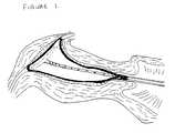
- the present inventionconsists of an apparatus which thermally ablates tissue by introducing heated fluid through pre-shaped balloon which is inserted into the uterus on the tip of a catheter.
- the pre-shapeis designed for two sizes nulliparuos and parous.
- the balloonis mechanically deployed in a 3 dimensional fashion to ensure the conforming of the pre-shaped balloon to the uterus and effectively treating the entire uterus.
- the apparatus of the present inventionmay be used according to a method of thermal ablation utilizing higher temperatures (above 104.4°C (220°F)) than previously used in prior art and for a shorter period of time. Furthermore the treatment may be performed twice to provide for even greater efficacy of the ablation technique.
- the apparatus of the present inventionprovides advantages over prior art to achieve more uniform and complete endometrial lining contact at monitored, higher temperatures for a more efficacious thermal ablation treatment. Specifically the accumulative advantages are provided by:
- front end reusable equipmenthas been designed to provide improved variable control at low costs to the end user.
- the heater/injector part ( I )contains: a variable capacity chamber ( 2 ) that provides reliable temperature pressure monitoring, vapor venting, vapor separation, and sufficient volume to prevent temperature decline through heat loss; a built-in temperature/pressure display ( 1 ) to provide a display T1-2 of temperature of the hot liquid -
- the liquidwill be solutions that will allow liquid temperatures in excess of 104.4°C (220°F) without risk of boiling. Examples of such solutions are mixtures of n-Butyl alcohol or similar even-numbered Carbon, non-toxic alcohols, glycerol, glycerol/water mixtures, and mineral oil) - in the endometrial ablator part ( II ) via a thermocouple located inside the balloon ( 7 ).
- pressure P1 and temperature T1-1 inside the heater/injector part ( I )is monitored; a pressure injection module ( 4 ) ergonometrically designed to provide easy and efficient control of liquid injection into the balloon, pressure regulation and liquid withdrawal from the balloon; a liquid capacity chamber ( 5 ) of sufficient volume to assure deliverance of up to 100 ml of temperature controlled liquid to the balloon for a dual ablation procedure; a specification standard immersion heater(s) or specification standard band heater(s) ( 3 ) fitted into or around the liquid heater/container ( 5 ) and is equipped with a regulator for temperature control connected by a standard cord plugged into a standard 110 V/ 60 cycle outlet and; stopcock valves for liquid charging, venting, draining and control of liquid movements into and out of the balloon, plus quick connect coupling to avoid introduction of air to purged part ( II ).
- an endometrial ablator part ( II )is comprised of : a pre-shaped inflatable balloon ( 7 ) which is sealed around the distal end of a catheter -
- the balloon materialis: flexible (softness, strength, workability similar to Latex) and; chemically resistant to n-Butyl alcohol or similar even-numbered Carbon, non-toxic alcohols, non-toxic alcohol-Glycerol solutions, non-toxic glycerol-water solutions, non-toxic mineral oil solutions at temperatures greater than 104.4°C (220°F); compatible with molding techniques; compatible with non-toxic, biocompatible coatings to prevent sticking to uterine cavities.); a catheter that delivers inflation liquid and couples as a position indicator ( 8 ) for both balloon depth and rotational orientation; an optional retractable sleeve ( 6 ) providing - a pre-sheathing of the balloon for ease of part ( II ) delivery, a restraint for an optional solid mechanical 3-dimensional balloon deployer ( 9 ) with positional memory and
- STEP 1Standard pre-sizing of uterus determines depth that device will be inserted.
- STEP 2Charge liquid to part (II) with valve to part ( I ) closed.
- STEP 3Heat liquid in the liquid/container ( 5 ) via the immersion heater ( 3 ) to desired temperature (>104.4°C (220°F))
- STEP 4Air is purged from part ( II ) by partially filling the system with saline solution. This partial filling is performed prior to insertion of the device into the uterus, with the retractable sleeve ( 6 )(if applicable) held in the distal position to prevent the balloon from inflating.
- STEP 5Connect part ( I ) to part ( II ).
- STEP 6Insert part (II) into uterus using position indicator ( 8 ) to ensure proper depth and rotational orientation of the pre-shaped balloon.
- STEP 7Pull back retractable sleeve (if applicable) ( 6 ).
- STEP 8Start timing and flush hot inflation liquid into part ( II ) for 30 - 90 seconds.
- STEP 9Monitor balloon temperature and when temperature is below 104.4°C (220°F) withdraw inflation liquid from part ( II ).
- STEP 10Repeat STEPS 8 and 9.
- STEP 11Drain liquid into disposable liquid container, or if part ( I ) is disposable discard part ( I ) and part ( II ). If part ( II ) is not disposable disconnect after draining and discard part ( II ).
Landscapes
- Health & Medical Sciences (AREA)
- Animal Behavior & Ethology (AREA)
- Veterinary Medicine (AREA)
- Engineering & Computer Science (AREA)
- Biomedical Technology (AREA)
- Heart & Thoracic Surgery (AREA)
- Vascular Medicine (AREA)
- Life Sciences & Earth Sciences (AREA)
- Physics & Mathematics (AREA)
- Thermal Sciences (AREA)
- General Health & Medical Sciences (AREA)
- Public Health (AREA)
- Media Introduction/Drainage Providing Device (AREA)
- Thermotherapy And Cooling Therapy Devices (AREA)
- Crystals, And After-Treatments Of Crystals (AREA)
- Physical Or Chemical Processes And Apparatus (AREA)
- Control And Other Processes For Unpacking Of Materials (AREA)
- Electrical Discharge Machining, Electrochemical Machining, And Combined Machining (AREA)
- Nonmetallic Welding Materials (AREA)
Abstract
Description
STEP 1: Standard pre-sizing of uterus determines depth that device will be inserted.
STEP 2: Charge liquid to part(II) with valve to part (I) closed.
STEP 3: Heat liquid in the liquid/container (5) via the immersion heater (3) to desiredtemperature (>104.4°C (220°F))
STEP 4: Air is purged from part (II) by partially filling the system with saline solution.This partial filling is performed prior to insertion of the device into the uterus, with theretractable sleeve (6)(if applicable) held in the distal position to prevent the balloon frominflating.
STEP 5: Connect part (I) to part (II).
STEP 6: Insert part(II) into uterus using position indicator (8) to ensure proper depthand rotational orientation of the pre-shaped balloon.
STEP 7: Pull back retractable sleeve (if applicable) (6).
STEP 8: Start timing and flush hot inflation liquid into part (II) for 30 - 90 seconds.
STEP 9: Monitor balloon temperature and when temperature is below 104.4°C (220°F) withdrawinflation liquid from part (II).
STEP 10: Repeat STEPS 8 and 9.
STEP 11: Drain liquid into disposable liquid container, or if part (I) is disposable discardpart (I) and part (II). If part (II) is not disposable disconnect after draining and discardpart (II).
Claims (3)
- An apparatus for thermally ablating tissue ina uterus, comprising:wherein the catheter has a longitudinal axis andwherein mechanical balloon deployment meansincludes deployment members that have two positions -a contracted position in which thedeployment members are substantially parallel tothe longitudinal axis and an extended position inwhich the members extend perpendicular to thelongitudinal axis of the catheter and attached atthe end of the catheter, thereby ensuring properballoon deployment and conformation to the insideof the uterine cavity.(a) a catheter having a proximal end and adistal end;(b) two-sizes of pre-shaped inflatableballoons, (for parous and nulliparousuteri) individually attached to thedistal end of the catheter which willconform to the shape of the uterus;(c) a balloon deployment system connectedto the distal end of the catheter thatis deployed via mechanical and/orhydraulic means that in turn engagesthe balloon and deploys the pre-shapedballoon;(d) a balloon inflation means for pushinginflation fluid through the capacitiveelement, the catheter and into theballoon;(e) a balloon deflation means forwithdrawing inflation fluid from theballoon, the catheter and from thecapacitive element;(f) a heating means for heating theinflation fluid to an elevatedtemperature of above 104.4°C (220°F)(g) a chamber to provide a capacitiveelement allowing reliable pressuremonitoring, vapor venting, vaporseparation and sufficient volume toprevent temperature decline throughheat loss; and
- The apparatus of claim 1 wherein the chamberincludes a volume of temperature-controlledliquid in a housing that has a volume-monitoringwindow.
- The apparatus of claim 1 further comprisingmeans to regulate and monitor pressure andtemperature of heated fluid and further providesa closed hydraulic system to reliably transferpressures to ensure balloon filling and emptying.
Applications Claiming Priority (3)
| Application Number | Priority Date | Filing Date | Title |
|---|---|---|---|
| CA2232726 | 1998-05-22 | ||
| CA002232726ACA2232726A1 (en) | 1998-05-22 | 1998-05-22 | Endometrial ablation method and apparatus |
| PCT/CA1999/000476WO1999060960A1 (en) | 1998-05-22 | 1999-05-19 | Endometrial ablation method and apparatus |
Publications (2)
| Publication Number | Publication Date |
|---|---|
| EP1054651A1 EP1054651A1 (en) | 2000-11-29 |
| EP1054651B1true EP1054651B1 (en) | 2003-04-23 |
Family
ID=4162235
Family Applications (1)
| Application Number | Title | Priority Date | Filing Date |
|---|---|---|---|
| EP99922015AExpired - LifetimeEP1054651B1 (en) | 1998-05-22 | 1999-05-19 | Endometrial ablation method and apparatus |
Country Status (6)
| Country | Link |
|---|---|
| EP (1) | EP1054651B1 (en) |
| AT (1) | ATE238015T1 (en) |
| AU (1) | AU3923499A (en) |
| CA (1) | CA2232726A1 (en) |
| DE (1) | DE69907144D1 (en) |
| WO (1) | WO1999060960A1 (en) |
Families Citing this family (11)
| Publication number | Priority date | Publication date | Assignee | Title |
|---|---|---|---|---|
| AU2001234038A1 (en)* | 2000-02-22 | 2001-09-03 | M.T.R.E. Advanced Technologies Ltd. | Heat exchanger |
| US6443947B1 (en) | 2000-03-01 | 2002-09-03 | Alexei Marko | Device for thermal ablation of a cavity |
| US7763033B2 (en) | 2006-10-18 | 2010-07-27 | Interlace Medical, Inc. | System and methods for preventing intravasation during intrauterine procedures |
| US8226635B2 (en) | 2006-10-23 | 2012-07-24 | Boston Scientific Scimed, Inc. | Device for circulating heated fluid |
| US9392935B2 (en) | 2006-11-07 | 2016-07-19 | Hologic, Inc. | Methods for performing a medical procedure |
| US9259233B2 (en) | 2007-04-06 | 2016-02-16 | Hologic, Inc. | Method and device for distending a gynecological cavity |
| US9095366B2 (en) | 2007-04-06 | 2015-08-04 | Hologic, Inc. | Tissue cutter with differential hardness |
| US8951274B2 (en) | 2007-04-06 | 2015-02-10 | Hologic, Inc. | Methods of high rate, low profile tissue removal |
| US20080281317A1 (en) | 2007-05-10 | 2008-11-13 | Fred Gobel | Endometrial Ablation catheter |
| US11903602B2 (en) | 2009-04-29 | 2024-02-20 | Hologic, Inc. | Uterine fibroid tissue removal device |
| US10722283B2 (en) | 2014-11-21 | 2020-07-28 | Lina Medical Aps | Apparatus for thermal ablation |
Family Cites Families (7)
| Publication number | Priority date | Publication date | Assignee | Title |
|---|---|---|---|---|
| US3924628A (en)* | 1972-12-01 | 1975-12-09 | William Droegemueller | Cyrogenic bladder for necrosing tissue cells |
| US4949718B1 (en) | 1988-09-09 | 1998-11-10 | Gynelab Products | Intrauterine cauterizing apparatus |
| US5084044A (en) | 1989-07-14 | 1992-01-28 | Ciron Corporation | Apparatus for endometrial ablation and method of using same |
| US5460628A (en)* | 1991-01-28 | 1995-10-24 | Neuwirth; Robert S. | Heated balloon medical apparatus with fluid agitating means |
| SE9300921L (en)* | 1993-03-19 | 1994-09-20 | Packard Dev Sa | Device for medical treatment |
| US5449380A (en) | 1993-09-17 | 1995-09-12 | Origin Medsystems, Inc. | Apparatus and method for organ ablation |
| US5746762A (en)* | 1996-06-24 | 1998-05-05 | Bass; Lawrence S. | Device and method for surgical flap dissection |
- 1998
- 1998-05-22CACA002232726Apatent/CA2232726A1/ennot_activeAbandoned
- 1999
- 1999-05-19AUAU39234/99Apatent/AU3923499A/ennot_activeAbandoned
- 1999-05-19ATAT99922015Tpatent/ATE238015T1/ennot_activeIP Right Cessation
- 1999-05-19EPEP99922015Apatent/EP1054651B1/ennot_activeExpired - Lifetime
- 1999-05-19DEDE69907144Tpatent/DE69907144D1/ennot_activeExpired - Lifetime
- 1999-05-19WOPCT/CA1999/000476patent/WO1999060960A1/enactiveIP Right Grant
Also Published As
| Publication number | Publication date |
|---|---|
| CA2232726A1 (en) | 1999-11-22 |
| WO1999060960A1 (en) | 1999-12-02 |
| EP1054651A1 (en) | 2000-11-29 |
| ATE238015T1 (en) | 2003-05-15 |
| AU3923499A (en) | 1999-12-13 |
| HK1032902A1 (en) | 2001-08-10 |
| DE69907144D1 (en) | 2003-05-28 |
Similar Documents
| Publication | Publication Date | Title |
|---|---|---|
| JP3665066B2 (en) | Heating balloon medical device having liquid stirring means | |
| US5449380A (en) | Apparatus and method for organ ablation | |
| JP4077603B2 (en) | Medical equipment | |
| US6066132A (en) | Articulating endometrial ablation device | |
| EP0433376B1 (en) | Cauterizing apparatus | |
| JP3749261B2 (en) | Intrauterine resection device | |
| EP2522290B1 (en) | Uterine therapy device | |
| EP2327382B1 (en) | Sterilisation device | |
| EP1054651B1 (en) | Endometrial ablation method and apparatus | |
| CN112826582A (en) | Steam ablation device for the treatment of menorrhagia | |
| HK1032902B (en) | Endometrial ablation method and apparatus | |
| AU646630C (en) | Intrauterine cauterizing apparatus and method | |
| HK1177412B (en) | Uterine therapy device | |
| HK1145956B (en) | Uterine therapy device | |
| HK1145955B (en) | Uterine therapy device |
Legal Events
| Date | Code | Title | Description |
|---|---|---|---|
| PUAI | Public reference made under article 153(3) epc to a published international application that has entered the european phase | Free format text:ORIGINAL CODE: 0009012 | |
| 17P | Request for examination filed | Effective date:20000928 | |
| AK | Designated contracting states | Kind code of ref document:A1 Designated state(s):AT BE CH CY DE DK ES FI FR GB GR IE IT LI LU MC NL PT SE | |
| 17Q | First examination report despatched | Effective date:20010814 | |
| GRAH | Despatch of communication of intention to grant a patent | Free format text:ORIGINAL CODE: EPIDOS IGRA | |
| GRAH | Despatch of communication of intention to grant a patent | Free format text:ORIGINAL CODE: EPIDOS IGRA | |
| GRAA | (expected) grant | Free format text:ORIGINAL CODE: 0009210 | |
| AK | Designated contracting states | Designated state(s):AT BE CH CY DE DK ES FI FR GB GR IE IT LI LU MC NL PT SE | |
| PG25 | Lapsed in a contracting state [announced via postgrant information from national office to epo] | Ref country code:NL Free format text:LAPSE BECAUSE OF FAILURE TO SUBMIT A TRANSLATION OF THE DESCRIPTION OR TO PAY THE FEE WITHIN THE PRESCRIBED TIME-LIMIT Effective date:20030423 Ref country code:LI Free format text:LAPSE BECAUSE OF FAILURE TO SUBMIT A TRANSLATION OF THE DESCRIPTION OR TO PAY THE FEE WITHIN THE PRESCRIBED TIME-LIMIT Effective date:20030423 Ref country code:IT Free format text:LAPSE BECAUSE OF FAILURE TO SUBMIT A TRANSLATION OF THE DESCRIPTION OR TO PAY THE FEE WITHIN THE PRESCRIBED TIME-LIMIT;WARNING: LAPSES OF ITALIAN PATENTS WITH EFFECTIVE DATE BEFORE 2007 MAY HAVE OCCURRED AT ANY TIME BEFORE 2007. THE CORRECT EFFECTIVE DATE MAY BE DIFFERENT FROM THE ONE RECORDED. Effective date:20030423 Ref country code:FR Free format text:LAPSE BECAUSE OF FAILURE TO SUBMIT A TRANSLATION OF THE DESCRIPTION OR TO PAY THE FEE WITHIN THE PRESCRIBED TIME-LIMIT Effective date:20030423 Ref country code:FI Free format text:LAPSE BECAUSE OF FAILURE TO SUBMIT A TRANSLATION OF THE DESCRIPTION OR TO PAY THE FEE WITHIN THE PRESCRIBED TIME-LIMIT Effective date:20030423 Ref country code:CH Free format text:LAPSE BECAUSE OF FAILURE TO SUBMIT A TRANSLATION OF THE DESCRIPTION OR TO PAY THE FEE WITHIN THE PRESCRIBED TIME-LIMIT Effective date:20030423 Ref country code:BE Free format text:LAPSE BECAUSE OF FAILURE TO SUBMIT A TRANSLATION OF THE DESCRIPTION OR TO PAY THE FEE WITHIN THE PRESCRIBED TIME-LIMIT Effective date:20030423 Ref country code:AT Free format text:LAPSE BECAUSE OF FAILURE TO SUBMIT A TRANSLATION OF THE DESCRIPTION OR TO PAY THE FEE WITHIN THE PRESCRIBED TIME-LIMIT Effective date:20030423 | |
| REG | Reference to a national code | Ref country code:GB Ref legal event code:FG4D | |
| REG | Reference to a national code | Ref country code:CH Ref legal event code:EP | |
| PG25 | Lapsed in a contracting state [announced via postgrant information from national office to epo] | Ref country code:LU Free format text:LAPSE BECAUSE OF NON-PAYMENT OF DUE FEES Effective date:20030519 Ref country code:IE Free format text:LAPSE BECAUSE OF NON-PAYMENT OF DUE FEES Effective date:20030519 Ref country code:CY Free format text:LAPSE BECAUSE OF FAILURE TO SUBMIT A TRANSLATION OF THE DESCRIPTION OR TO PAY THE FEE WITHIN THE PRESCRIBED TIME-LIMIT Effective date:20030519 | |
| REF | Corresponds to: | Ref document number:69907144 Country of ref document:DE Date of ref document:20030528 Kind code of ref document:P | |
| REG | Reference to a national code | Ref country code:IE Ref legal event code:FG4D | |
| PG25 | Lapsed in a contracting state [announced via postgrant information from national office to epo] | Ref country code:MC Free format text:LAPSE BECAUSE OF NON-PAYMENT OF DUE FEES Effective date:20030531 | |
| PG25 | Lapsed in a contracting state [announced via postgrant information from national office to epo] | Ref country code:SE Free format text:LAPSE BECAUSE OF FAILURE TO SUBMIT A TRANSLATION OF THE DESCRIPTION OR TO PAY THE FEE WITHIN THE PRESCRIBED TIME-LIMIT Effective date:20030723 Ref country code:PT Free format text:LAPSE BECAUSE OF FAILURE TO SUBMIT A TRANSLATION OF THE DESCRIPTION OR TO PAY THE FEE WITHIN THE PRESCRIBED TIME-LIMIT Effective date:20030723 Ref country code:GR Free format text:LAPSE BECAUSE OF FAILURE TO SUBMIT A TRANSLATION OF THE DESCRIPTION OR TO PAY THE FEE WITHIN THE PRESCRIBED TIME-LIMIT Effective date:20030723 Ref country code:DK Free format text:LAPSE BECAUSE OF FAILURE TO SUBMIT A TRANSLATION OF THE DESCRIPTION OR TO PAY THE FEE WITHIN THE PRESCRIBED TIME-LIMIT Effective date:20030723 | |
| PG25 | Lapsed in a contracting state [announced via postgrant information from national office to epo] | Ref country code:DE Free format text:LAPSE BECAUSE OF FAILURE TO SUBMIT A TRANSLATION OF THE DESCRIPTION OR TO PAY THE FEE WITHIN THE PRESCRIBED TIME-LIMIT Effective date:20030724 | |
| NLV1 | Nl: lapsed or annulled due to failure to fulfill the requirements of art. 29p and 29m of the patents act | ||
| PG25 | Lapsed in a contracting state [announced via postgrant information from national office to epo] | Ref country code:ES Free format text:LAPSE BECAUSE OF FAILURE TO SUBMIT A TRANSLATION OF THE DESCRIPTION OR TO PAY THE FEE WITHIN THE PRESCRIBED TIME-LIMIT Effective date:20031030 | |
| REG | Reference to a national code | Ref country code:CH Ref legal event code:PL | |
| PLBE | No opposition filed within time limit | Free format text:ORIGINAL CODE: 0009261 | |
| STAA | Information on the status of an ep patent application or granted ep patent | Free format text:STATUS: NO OPPOSITION FILED WITHIN TIME LIMIT | |
| REG | Reference to a national code | Ref country code:IE Ref legal event code:MM4A | |
| 26N | No opposition filed | Effective date:20040126 | |
| EN | Fr: translation not filed | ||
| REG | Reference to a national code | Ref country code:GB Ref legal event code:732E | |
| PGFP | Annual fee paid to national office [announced via postgrant information from national office to epo] | Ref country code:GB Payment date:20120516 Year of fee payment:14 | |
| GBPC | Gb: european patent ceased through non-payment of renewal fee | Effective date:20130519 | |
| PG25 | Lapsed in a contracting state [announced via postgrant information from national office to epo] | Ref country code:GB Free format text:LAPSE BECAUSE OF NON-PAYMENT OF DUE FEES Effective date:20130519 |