EP1050866B1 - Parking assistance device and method - Google Patents
Parking assistance device and methodDownload PDFInfo
- Publication number
- EP1050866B1 EP1050866B1EP00108855AEP00108855AEP1050866B1EP 1050866 B1EP1050866 B1EP 1050866B1EP 00108855 AEP00108855 AEP 00108855AEP 00108855 AEP00108855 AEP 00108855AEP 1050866 B1EP1050866 B1EP 1050866B1
- Authority
- EP
- European Patent Office
- Prior art keywords
- vehicle
- locus
- estimate
- steering angle
- parking
- Prior art date
- Legal status (The legal status is an assumption and is not a legal conclusion. Google has not performed a legal analysis and makes no representation as to the accuracy of the status listed.)
- Expired - Lifetime
Links
Images


Classifications
- B—PERFORMING OPERATIONS; TRANSPORTING
- B62—LAND VEHICLES FOR TRAVELLING OTHERWISE THAN ON RAILS
- B62D—MOTOR VEHICLES; TRAILERS
- B62D15/00—Steering not otherwise provided for
- B62D15/02—Steering position indicators ; Steering position determination; Steering aids
- B62D15/027—Parking aids, e.g. instruction means
- B62D15/0275—Parking aids, e.g. instruction means by overlaying a vehicle path based on present steering angle over an image without processing that image
- B—PERFORMING OPERATIONS; TRANSPORTING
- B62—LAND VEHICLES FOR TRAVELLING OTHERWISE THAN ON RAILS
- B62D—MOTOR VEHICLES; TRAILERS
- B62D15/00—Steering not otherwise provided for
- B62D15/02—Steering position indicators ; Steering position determination; Steering aids
- B62D15/027—Parking aids, e.g. instruction means
- G—PHYSICS
- G08—SIGNALLING
- G08G—TRAFFIC CONTROL SYSTEMS
- G08G1/00—Traffic control systems for road vehicles
- G08G1/16—Anti-collision systems
- G08G1/168—Driving aids for parking, e.g. acoustic or visual feedback on parking space
- B—PERFORMING OPERATIONS; TRANSPORTING
- B60—VEHICLES IN GENERAL
- B60T—VEHICLE BRAKE CONTROL SYSTEMS OR PARTS THEREOF; BRAKE CONTROL SYSTEMS OR PARTS THEREOF, IN GENERAL; ARRANGEMENT OF BRAKING ELEMENTS ON VEHICLES IN GENERAL; PORTABLE DEVICES FOR PREVENTING UNWANTED MOVEMENT OF VEHICLES; VEHICLE MODIFICATIONS TO FACILITATE COOLING OF BRAKES
- B60T2201/00—Particular use of vehicle brake systems; Special systems using also the brakes; Special software modules within the brake system controller
- B60T2201/10—Automatic or semi-automatic parking aid systems
Definitions
- the present inventionis generally relates to a parking conduct device and method thereof for conducting or guiding a parking of a vehicle, and in particular to a parking conduct device and method of displaying a position of a vehicle on a plan view with calculating an estimate movement locus of a vehicle body when the vehicle is moved at a predetermined steering angle with respect to the vehicle position.
- a driver of the vehiclecan easily and quickly park the vehicle with accuracy and safety while monitoring the estimate movement locus of the vehicle on a display screen.
- a conventional parking conduct device of a loaded-on-vehicle typeis suggested, for example, in Japanese Patent Laid Open Unexamined Publication 7-114700 (in 1995), a block construction example thereof being shown in Fig. 5.
- the conventional parking conduct deviceincludes an image input unit 51 for picking up an image of a surrounding sight of the vehicle, an image memory 52 for storing the input image data, an image processor unit 53 for extracting features of the input image data, a driver input unit 54 for the driver to operate such as a starting of a parking, a learning unit 55 for learning the processed image data, a learning data recording memory 57 for recording the learned results, a danger judging unit 56 for judging danger by comparing the input image with the learned data, and an output unit 58 for generating a warning alarm to the driver.
- an image input unit 51for picking up an image of a surrounding sight of the vehicle
- an image memory 52for storing the input image data
- an image processor unit 53for extracting features of the input image data
- a driver input unit 54for the driver to operate such as a starting of a parking
- a learning unit 55for learning the processed image data
- a learning data recording memory 57for recording the learned results
- a danger judging unit 56for judging danger by comparing the
- the image input unit 51such as an image pickup camera is attached to a rear part of the vehicle to pick up an image of a backward sight picture outside the vehicle.
- the input imageis stored in the image memory 52.
- the image processor unit 53Based on the input image stored in the image memory 52, the image processor unit 53 extracts information of the backsight picture, for example, existence of a wall or a pole standing, or a block placed. Then, the driver executes the starting operation of the parking by means of the driver input unit 54 and the resultant image data processed by the image processor unit 53 is learned by the learning unit 55.
- the learned resultant datais recorded in the learning data recording memory 57.
- the learned resultant data stored in the learning data recording memory 57 and the input image of the backsight picture output of the image processor unit 53are compared by the danger judging unit 56. Based on the comparison result, when it is judged to be danger to park the vehicle as it is, the output device 58 gives, for example, a warning alarm to the driver.
- one aspect of the inventionprovides a parking conduct device which comprises: a vehicle position calculation unit for calculating a position of a vehicle on a plan view; an estimate locus calculation unit for calculating an estimate movement locus of a vehicle body when the vehicle is moved at a predetermined steering angle with respect to the vehicle position calculated by the vehicle position calculation unit; and a display unit for displaying the vehicle position calculated by the vehicle position calculation unit together with the estimate locus of the vehicle body calculated by the estimate locus calculation unit.
- the predetermined steering angleis the maximum steering angle of the vehicle
- the display unitdisplays the vehicle position calculated by the vehicle position calculation unit, by superimposing a contour of the vehicle body onto the estimate movement locus of the vehicle body calculated by the estimate locus calculation unit.
- Another aspect of the inventionprovides a parking conduct method which comprises the steps of: calculating a position of a vehicle on a plan view; calculating an estimate movement locus of a vehicle body when the vehicle is moved at a predetermined steering angle with respect to the vehicle position calculated in the vehicle position calculation step; and displaying the vehicle position calculated in the vehicle position calculation step together with the estimate locus of the vehicle body calculated in the estimate locus calculation step.
- the predetermined steering angleis the maximum steering angle of the vehicle
- the display of the vehicle position calculated in the vehicle position calculation stepis performed by superimposing a contour of the vehicle body onto the estimate movement locus of the vehicle body calculated by the estimate locus calculation step.
- Fig. 1shows a schematic block construction of a preferred embodiment of a parking conduct device according to the present invention.
- the parking conduct deviceincludes a vehicle position calculation unit 1, a movement locus calculation unit 2 and a display unit 3.
- the vehicle position calculation unit 1has a function of depicting a driver's own vehicle by calculating a position of the vehicle on a plan view to be displayed on a display screen.
- the movement locus calculation unit 2calculates an estimate movement locus of a vehicle body to be displayed when the vehicle is moved at a predetermined steering angle such as a maximum steering angle with respect to the vehicle position calculated by the vehicle position calculation unit 1.
- the display of the estimate movement locus of the vehicle bodyincludes four corners or four wheels of the vehicle.
- the display unit 3 for displaying the calculated resultantsmay be constructed as a display device such as a liquid crystal display integrally combined with the parking conduct device which is installed in a position inside the vehicle for the driver to easily monitor the display on the screen.
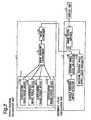
- Fig. 2shows an example of constitution components of the parking conduct device comprised of the vehicle position calculation unit 1 and movement locus calculation unit 2.
- the vehicle position calculation unit 1includes an image pickup portion 11, an image viewpoint transformer portion 12 and an image composer portion 13.
- the image pickup portion 11is comprised of a plurality of vehicle surrounding image pickup devices 11a, 11b, 11c, ..., 11d which may be comprised of one or more image pickup cameras fixedly mounted on predetermined outer periphery positions of the vehicle.
- the plurality of the pickup devices 11a, 11b, 11c, ..., 11dhave a function of an image input means so that each of the image pickup devices picks up a sight picture image of surroundings of the vehicle to generate the image data thereof which is applied to the image viewpoint transformer portion 12.
- the image viewpoint transformer portion 12forms a bird's-eye view of the surrounding sight picture based on the image data generated by the image pickup portion 11 by way of a projection transformation process to transform the input image data of the surrounding sight picture in order to depict the vehicle position from optional viewpoints in the bird's-eye view of the surrounding sight picture.
- the image composer portion 13depicts a composite image using the bird's-eye view of the surrounding sight picture obtained by the image viewpoint transformer portion 12.
- the vehicle body composed on the bird's-eye view of the surrounding sight pictureis depicted on the plan view.
- the resultant depicted composite image of the vehicle body composed on the bird's-eye view of the surrounding sight pictureis transmitted from the image composer portion 13 to the movement locus calculation unit 2.
- the movement locus calculation unit 2includes a handle steering angle detector portion 21, a steering wheel locus calculator portion 22, a maximum steering angle wheel locus calculator portion 23, and an image superimposer portion 24.
- the handle steering angle detector portion 21is secured to a fixed position of a handle mechanism to detect a handle steering angle.
- the steering wheel locus calculator portion 22receives the detected handle steering angle to thereby calculates an estimate movement locus of the vehicle to be assumed to move based on the handle steering angle.
- the maximum steering angle wheel locus calculator portion 23calculates a vehicle wheel locus when the vehicle is moved at the maximum handle steering angle.
- the estimate movement locus of the vehicle obtained by the steering wheel locus calculator portion 22. or the maximum steering angle wheel locus obtained by the maximum steering angle wheel locus calculator portion 23is applied to the image superimposer portion 24 so that the applied steering wheel locus is superimposed to the composite image of the vehicle body transmitted from the image composer portion 13.
- the resultant superimposed image obtained by the image superimposer portion 24is displayed on the display screen of the display unit 3 to be monitored by the driver.
- Fig. 3shows an example of a displayed contents displayed on the screen of the display unit 3
- Fig. 4shows a flow chart for explaining the operation.
- boundary lines 30 of parking partitionsare displayed on a plan view of the display screen and a vehicle position or a contour of the vehicle body is displayed on the plan view of the screen in association with the parking partitions to be monitored by the driver.
- a parking lotis allocated to ten partitions by, e.g., white boundary lines having a parking capacity of e.g. ten cars of which four cars have been already stored.
- An outstanding vehicle (35) in relation to the parking partitions 30 on the plan viewis displayed in a manner as described below.
- a surrounding sight picture outside the vehicleis picked up by a plurality of image pickup devices such as cameras which are securely attached to predetermined positions of the vehicle.
- the input image data of the surrounding sight pictureis transformed to a bird's-eye view by way of an affine transformation process in step S2.
- the image composer portion 13depicts a composite image of the vehicle body composed with the bird's-eye view of the surrounding sight picture in step S3.
- an estimate locus of the vehicle positionis displayed in the case where the vehicle body obtained in the operation of the vehicle position calculation unit 1 is first moved forward at a predetermined steering angle for leftward turning rotation and is then moved backward at a predetermined steering angle for rightward turning rotation.
- the handle steering angle of the vehicleis detected by the handle steering angle detector portion 21 attached to the handle position in step S4.
- an estimate locus of the vehicle position to be movedis calculated by the steering wheel locus calculator portion 22 based on the handle steering angle detected in step S4 with respect to the composite image of the vehicle body composed obtained in step S3.
- the maximum steering anglemay be used as the predetermined steering angles for both leftward and rightward turning rotations so that the maximum steering angle wheel locus is calculated to be displayed in step S6 by means of the maximum steering angle wheel locus calculator portion 23 assuming that the vehicle is moved at the maximum handle steering angle.
- step S7the estimate locus of the vehicle movement calculated in the steering wheel locus calculation step S5 is superimposed with the composite image of the vehicle body obtained in the image composing step S3.
- the maximum steering angle wheel locus calculated in step S6is used to be superimposed with the composite image of the vehicle body.
- the resultant superimposed image obtained in step S7is displayed on the display screen to be monitored by the driver.
- the estimate movement loci of the four corners of the vehicle body 35namely, a forward movement locus 31a of a right front corner, a backward movement locus 31b of a left front corner, a forward movement locus 32 of right and left rear corners, and backward movement loci 33 of the right and left rear corners are depicted on the display screen as the estimate locus of the vehicle movement.
- the backward movement loci 33can be depicted based on the minimum rotation radius r min defined according to the maximum steering angle of the vehicle together with the fixed vehicle body size on the premise that a rotation center O of the loci is located on a straight line 34 passing through the centers of the right and left rear wheels.
- the display contentsare displayed on the screen of the display unit 3 as shown in Fig. 3 so that the driver operates the handle steering while monitoring the display screen.
- the vehicleis moved forward at the predetermined steering angle for leftward turning rotation, the vehicle is stopped at a position 35 in Fig. 3 where the estimate loci 33 of the rear corners of the vehicle body are in parallel to the side boundary lines of a target parking partition. Then, the driver operates the handle steering angle to be maximum for rightward turning rotation and moves the vehicle backward at the maximum steering angle under the same condition while monitoring the vehicle position on the display screen.
- the vehicleis moved back to a position 36 within the target partition as shown in Fig.
- the driverreturns back the handle to the original condition, namely, the condition of the steering angle equal to zero. Then, the vehicle is straightly moved backward to be thereby accurately parked within the target partition.
- the handle steering anglemay be displayed on the screen along the vehicle body on the plan view shown in Fig. 3.
- a single image pickup cameramay be used therefor.
- the maximum steering angleis used as the predetermined steering angle to calculate the maximum steering angle wheel locus in step S6. This is because for a beginner driver of a car to facilitate a quick and accurate parking of the car. However, it is not limited to this and other predetermined steering angle may be, of course, used therefor.
- a parking conduct devicecomprises: a vehicle position calculation unit for calculating a position of a vehicle on a plan view; an estimate locus calculation unit for calculating an estimate movement locus of a vehicle body when the vehicle is moved at a predetermined steering angle with respect to the vehicle position calculated by the vehicle position calculation unit; and a display unit for displaying the vehicle position calculated by the vehicle position calculation unit together with the estimate locus of the vehicle body calculated by the estimate locus calculation unit.
- the predetermined steering angleis the maximum steering angle of the vehicle
- the display unitdisplays the vehicle position calculated by the vehicle position calculation unit, by superimposing a contour of the vehicle body onto the estimate movement locus of the vehicle body calculated by the estimate locus calculation unit.
- the display of the estimate locus of the vehicle body calculated by the estimate locus calculation unitincludes a display of four corner parts of the vehicle including four wheels, and the display of the estimate locus of the vehicle body calculated by the estimate locus calculation unit includes a display of a line passing through the centers of rear wheels.
- the vehicle position calculation unitincludes: an image input portion for picking up a picture of surroundings of the vehicle to generate image data thereof; a bird's-eye view forming portion for forming a bird's-eye view of the surrounding picture based on the image data generated by the image input portion; and an image composing portion for depicting a composite image of the vehicle body composed on the bird's-eye view of the surrounding picture.
- the estimate locus calculation unitincludes: a steering angle detection portion for detecting a handle steering angle of the vehicle; a steering wheel locus calculation portion for calculating an estimate locus of the vehicle position to be moved based on the handle steering angle; and an image superimposing portion for superimposing the estimate locus of the vehicle movement calculated by the steering wheel locus calculation portion with the composite image of the vehicle body depicted by the image composing portion.
- the estimate locus calculation unitmay further include a maximum steering angle wheel locus calculation portion for calculating a vehicle wheel locus when the vehicle is moved at the maximum handle steering angle.
- a parking conduct methodcomprises steps of: calculating a position of a vehicle on a plan view; calculating an estimate movement locus of a vehicle body when the vehicle is moved at a predetermined steering angle with respect to the vehicle position calculated in the vehicle position calculation step; and displaying the vehicle position calculated in the vehicle position calculation step together with the estimate locus of the vehicle body calculated in the estimate locus calculation step.
- the predetermined steering angleis the maximum steering angle of the vehicle
- the display of the vehicle position calculated in the vehicle position calculation stepis performed by superimposing a contour of the vehicle body onto the estimate movement locus of the vehicle body calculated by the estimate locus calculation step.
- the vehicle position calculation stepincludes: an image input step for picking up a picture of surroundings of the vehicle to generate image data thereof; a bird's-eye view forming step for forming a bird's-eye view of the surrounding picture based on the image data generated in the image input step; and an image composing step for depicting a composite image of the vehicle body composed on the bird's-eye view of the surrounding picture.
- the display of the vehicle positionincludes boundary lines of parking partitions and a backward movement of the vehicle is started when the displayed estimate locus of the vehicle body is in parallel to the boundary lines of a target parking partition.
- a position of a vehicle on a plan viewis calculated to be displayed in relation to partition lines of a parking lot, and an estimate movement locus of a vehicle body or vehicle wheels when the vehicle is moved back with a minimum rotation radius, i.e., at a maximum steering angle with respect to the vehicle position so that the vehicle position calculated in the vehicle position calculation together with the estimate locus of the vehicle body calculated in the estimate locus calculation is displayed on the display screen.
Landscapes
- Engineering & Computer Science (AREA)
- Chemical & Material Sciences (AREA)
- Combustion & Propulsion (AREA)
- Transportation (AREA)
- Mechanical Engineering (AREA)
- Physics & Mathematics (AREA)
- General Physics & Mathematics (AREA)
- Closed-Circuit Television Systems (AREA)
- Traffic Control Systems (AREA)
- Image Processing (AREA)
Description
- The present invention is generally relates to aparking conduct device and method thereof for conducting orguiding a parking of a vehicle, and in particular to aparking conduct device and method of displaying a positionof a vehicle on a plan view with calculating an estimatemovement locus of a vehicle body when the vehicle is movedat a predetermined steering angle with respect to thevehicle position. Thus, a driver of the vehicle can easilyand quickly park the vehicle with accuracy and safety whilemonitoring the estimate movement locus of the vehicle on adisplay screen.
- In order to facilitate a smooth parking of avehicle in a parking lot, a conventional parking conductdevice of a loaded-on-vehicle type is suggested, forexample, in Japanese Patent Laid Open UnexaminedPublication 7-114700 (in 1995), a block constructionexample thereof being shown in Fig. 5.
- In Fig. 5, the conventional parking conductdevice includes an
image input unit 51 for picking up animage of a surrounding sight of the vehicle, animage memory 52 for storing the input image data, animageprocessor unit 53 for extracting features of the inputimage data, adriver input unit 54 for the driver tooperate such as a starting of a parking, alearning unit 55for learning the processed image data, a learningdatarecording memory 57 for recording the learned results, adanger judging unit 56 for judging danger by comparing theinput image with the learned data, and anoutput unit 58for generating a warning alarm to the driver. - In this conventional construction, the
imageinput unit 51 such as an image pickup camera is attached toa rear part of the vehicle to pick up an image of abackward sight picture outside the vehicle. The inputimage is stored in theimage memory 52. Based on the inputimage stored in theimage memory 52, theimage processorunit 53 extracts information of the backsight picture, forexample, existence of a wall or a pole standing, or a blockplaced. Then, the driver executes the starting operationof the parking by means of thedriver input unit 54 and theresultant image data processed by theimage processor unit 53 is learned by thelearning unit 55. The learnedresultant data is recorded in the learningdata recordingmemory 57. The learned resultant data stored in thelearningdata recording memory 57 and the input image ofthe backsight picture output of theimage processor unit 53 are compared by thedanger judging unit 56. Based on thecomparison result, when it is judged to be danger to parkthe vehicle as it is, theoutput device 58 gives, forexample, a warning alarm to the driver. - In this conventional technique, however, sincethe danger is merely judged based on the comparison betweenthe input image data and the learned resultant data, it wasstill difficult for a beginner having just taken an auto-drivinglicense to park a vehicle, and also difficult for adriver to park an inexperienced vehicle such as a large-sizedvehicle of another person. This is because the sizeof the vehicle body and the actual rotating angle of thewheel with respect to a handle steering angle are bothvaried according to various different types of vehicles.
- It is an object of the present invention toprovide an improved parking conduct device and methodthereof for conducting a parking of a vehicle, depicting aposition of the vehicle on a plan view with calculating anestimate movement locus of a vehicle body when the vehicleis moved at a predetermined steering angle with respect tothe vehicle position, so that a driver of the vehicle caneasily and quickly park the vehicle with accuracy andsafety while monitoring the estimate movement locus of thevehicle on a display screen.
- In order to attain the object, one aspect of theinvention provides a parking conduct device whichcomprises: a vehicle position calculation unit forcalculating a position of a vehicle on a plan view; anestimate locus calculation unit for calculating an estimatemovement locus of a vehicle body when the vehicle is movedat a predetermined steering angle with respect to thevehicle position calculated by the vehicle positioncalculation unit; and a display unit for displaying thevehicle position calculated by the vehicle positioncalculation unit together with the estimate locus of thevehicle body calculated by the estimate locus calculationunit.
- In this construction, the predetermined steeringangle is the maximum steering angle of the vehicle, and thedisplay unit displays the vehicle position calculated bythe vehicle position calculation unit, by superimposing acontour of the vehicle body onto the estimate movementlocus of the vehicle body calculated by the estimate locuscalculation unit.
- Another aspect of the invention provides aparking conduct method which comprises the steps of:calculating a position of a vehicle on a plan view;calculating an estimate movement locus of a vehicle bodywhen the vehicle is moved at a predetermined steering angle with respect to the vehicle position calculated in thevehicle position calculation step; and displaying thevehicle position calculated in the vehicle positioncalculation step together with the estimate locus of thevehicle body calculated in the estimate locus calculationstep.
- In this method, the predetermined steering angleis the maximum steering angle of the vehicle, and thedisplay of the vehicle position calculated in the vehicleposition calculation step is performed by superimposing acontour of the vehicle body onto the estimate movementlocus of the vehicle body calculated by the estimate locuscalculation step.
- By this arrangement, even a beginner driver ofthe vehicle can easily and quickly park the vehicle withaccuracy and safety while monitoring the estimate movementlocus of the vehicle on a display screen.
- The foregoing and other features, aspects andadvantages of the invention will become better understoodwith regard to the following description, appended claimsand accompanying drawings in which:
- Fig. 1 is a block diagram showing a genericconfiguration of a parking conduct device according to thepresent invention;
- Fig. 2 is a block diagram showing components of avehicle position calculation unit and a movement locuscalculation unit according to the present invention;
- Fig. 3 is an explanatory view showing an exampleof a displayed picture on a display screen according to thepresent invention;
- Fig. 4 is a flow chart for explaining anoperation of the parking conduct device according to thepresent invention; and
- Fig. 5 is a block diagram showing a configurationof a conventional parking conduct device.
- Although the following detailed descriptioncontains many specifics for the purposes of illustrations,anyone of ordinary skill in the art will appreciate thatmany variations and alterations to the following detailsare within the scope of the invention. Accordingly, thefollowing preferred embodiments of the invention are setforth without any loss of generality to, and withoutimposing limitations upon, the claimed invention.
- Fig. 1 shows a schematic block construction of apreferred embodiment of a parking conduct device accordingto the present invention. In this construction, theparking conduct device includes a vehicle
positioncalculation unit 1, a movementlocus calculation unit 2 and adisplay unit 3. The vehicleposition calculation unit 1has a function of depicting a driver's own vehicle bycalculating a position of the vehicle on a plan view to bedisplayed on a display screen. - The movement
locus calculation unit 2 calculatesan estimate movement locus of a vehicle body to bedisplayed when the vehicle is moved at a predeterminedsteering angle such as a maximum steering angle withrespect to the vehicle position calculated by the vehicleposition calculation unit 1. The display of the estimatemovement locus of the vehicle body includes four corners orfour wheels of the vehicle. Thedisplay unit 3 fordisplaying the calculated resultants may be constructed asa display device such as a liquid crystal displayintegrally combined with the parking conduct device whichis installed in a position inside the vehicle for thedriver to easily monitor the display on the screen. - Fig. 2 shows an example of constitutioncomponents of the parking conduct device comprised of thevehicle
position calculation unit 1 and movementlocuscalculation unit 2. The vehicleposition calculation unit 1 includes animage pickup portion 11, an imageviewpointtransformer portion 12 and animage composer portion 13.Theimage pickup portion 11 is comprised of a plurality ofvehicle surroundingimage pickup devices pickupdevices viewpoint transformer portion 12. - The image
viewpoint transformer portion 12 formsa bird's-eye view of the surrounding sight picture based onthe image data generated by theimage pickup portion 11 byway of a projection transformation process to transform theinput image data of the surrounding sight picture in orderto depict the vehicle position from optional viewpoints inthe bird's-eye view of the surrounding sight picture. - The
image composer portion 13 depicts a compositeimage using the bird's-eye view of the surrounding sightpicture obtained by the imageviewpoint transformer portion 12. Thus, the vehicle body composed on the bird's-eye viewof the surrounding sight picture is depicted on the planview. The resultant depicted composite image of thevehicle body composed on the bird's-eye view of thesurrounding sight picture is transmitted from theimagecomposer portion 13 to the movementlocus calculation unit 2. - The movement
locus calculation unit 2 includes ahandle steeringangle detector portion 21, a steering wheellocus calculator portion 22, a maximum steering angle wheellocus calculator portion 23, and animage superimposerportion 24. - The handle steering
angle detector portion 21 issecured to a fixed position of a handle mechanism to detecta handle steering angle. The steering wheellocuscalculator portion 22 receives the detected handle steeringangle to thereby calculates an estimate movement locus ofthe vehicle to be assumed to move based on the handlesteering angle. The maximum steering angle wheellocuscalculator portion 23 calculates a vehicle wheel locus whenthe vehicle is moved at the maximum handle steering angle. - The estimate movement locus of the vehicleobtained by the steering wheel
locus calculator portion 22.or the maximum steering angle wheel locus obtained by themaximum steering angle wheellocus calculator portion 23 isapplied to theimage superimposer portion 24 so that theapplied steering wheel locus is superimposed to thecomposite image of the vehicle body transmitted from theimage composer portion 13. The resultant superimposedimage obtained by theimage superimposer portion 24 isdisplayed on the display screen of thedisplay unit 3 to bemonitored by the driver. - The following describes an operation of theparking conduct device of the present embodiment withreference to Figs. 3 and 4, where Fig. 3 shows an exampleof a displayed contents displayed on the screen of the
display unit 3 and Fig. 4 shows a flow chart for explainingthe operation. - In the operation of the vehicle
positioncalculation unit 1, as shown in Fig. 3,boundary lines 30of parking partitions are displayed on a plan view of thedisplay screen and a vehicle position or a contour of thevehicle body is displayed on the plan view of the screen inassociation with the parking partitions to be monitored bythe driver. In this example shown in Fig. 3, a parking lotis allocated to ten partitions by, e.g., white boundarylines having a parking capacity of e.g. ten cars of whichfour cars have been already stored. - An outstanding vehicle (35) in relation to the
parking partitions 30 on the plan view is displayed in amanner as described below. - In the first step S1, a surrounding sight pictureoutside the vehicle is picked up by a plurality of imagepickup devices such as cameras which are securely attachedto predetermined positions of the vehicle. The input imagedata of the surrounding sight picture is transformed to abird's-eye view by way of an affine transformation process in step S2. Then, the
image composer portion 13 depicts acomposite image of the vehicle body composed with thebird's-eye view of the surrounding sight picture in step S3. - Next, in the example of the operation of themovement
locus calculation unit 2 as shown in Fig. 3, anestimate locus of the vehicle position is displayed in thecase where the vehicle body obtained in the operation ofthe vehicleposition calculation unit 1 is first movedforward at a predetermined steering angle for leftwardturning rotation and is then moved backward at apredetermined steering angle for rightward turning rotation.In this display operation, firstly, the handle steeringangle of the vehicle is detected by the handle steeringangle detector portion 21 attached to the handle positionin step S4. Subsequently in step S5, an estimate locus ofthe vehicle position to be moved is calculated by thesteering wheellocus calculator portion 22 based on thehandle steering angle detected in step S4 with respect tothe composite image of the vehicle body composed obtainedin step S3. - In this example, the maximum steering angle maybe used as the predetermined steering angles for bothleftward and rightward turning rotations so that themaximum steering angle wheel locus is calculated to bedisplayed in step S6 by means of the maximum steering angle wheel
locus calculator portion 23 assuming that the vehicleis moved at the maximum handle steering angle. Then, instep S7, the estimate locus of the vehicle movementcalculated in the steering wheel locus calculation step S5is superimposed with the composite image of the vehiclebody obtained in the image composing step S3. In thisexample, the maximum steering angle wheel locus calculatedin step S6 is used to be superimposed with the compositeimage of the vehicle body. The resultant superimposedimage obtained in step S7 is displayed on the display screento be monitored by the driver. - Specifically, in the example shown in Fig. 3, theestimate movement loci of the four corners of the
vehiclebody 35, namely, aforward movement locus 31a of a rightfront corner, abackward movement locus 31b of a left frontcorner, aforward movement locus 32 of right and left rearcorners, and backward movement loci 33 of the right andleft rear corners are depicted on the display screen as theestimate locus of the vehicle movement. In thisarrangement, the backward movement loci 33 can be depictedbased on the minimum rotation radius rmin defined accordingto the maximum steering angle of the vehicle together withthe fixed vehicle body size on the premise that a rotationcenter O of the loci is located on astraight line 34passing through the centers of the right and left rear wheels. - When a driver parks a vehicle using the parkingconduct device of the present invention, the displaycontents are displayed on the screen of the
display unit 3as shown in Fig. 3 so that the driver operates the handlesteering while monitoring the display screen. When thevehicle is moved forward at the predetermined steeringangle for leftward turning rotation, the vehicle is stoppedat aposition 35 in Fig. 3 where the estimate loci 33 ofthe rear corners of the vehicle body are in parallel to theside boundary lines of a target parking partition. Then,the driver operates the handle steering angle to be maximumfor rightward turning rotation and moves the vehiclebackward at the maximum steering angle under the samecondition while monitoring the vehicle position on thedisplay screen. When the vehicle is moved back to aposition 36 within the target partition as shown in Fig. 3where the vehicle body is in parallel to the both sideboundary lines of the target partition, the driver returnsback the handle to the original condition, namely, thecondition of the steering angle equal to zero. Then, thevehicle is straightly moved backward to be therebyaccurately parked within the target partition. In thisarrangement, the handle steering angle may be displayed onthe screen along the vehicle body on the plan view shown in Fig. 3. - In the present embodiment, although a pluralityof image pickup cameras are used for forming a bird's-eyeview, a single image pickup camera may be used therefor.
- Moreover, the maximum steering angle is used asthe predetermined steering angle to calculate the maximumsteering angle wheel locus in step S6. This is because fora beginner driver of a car to facilitate a quick andaccurate parking of the car. However, it is not limited tothis and other predetermined steering angle may be, ofcourse, used therefor.
- As described above, according to a first aspectof the present invention, a parking conduct devicecomprises: a vehicle position calculation unit forcalculating a position of a vehicle on a plan view; anestimate locus calculation unit for calculating an estimatemovement locus of a vehicle body when the vehicle is movedat a predetermined steering angle with respect to thevehicle position calculated by the vehicle positioncalculation unit; and a display unit for displaying thevehicle position calculated by the vehicle positioncalculation unit together with the estimate locus of thevehicle body calculated by the estimate locus calculationunit.
- In this construction, the predetermined steering angle is the maximum steering angle of the vehicle, and thedisplay unit displays the vehicle position calculated bythe vehicle position calculation unit, by superimposing acontour of the vehicle body onto the estimate movementlocus of the vehicle body calculated by the estimate locuscalculation unit.
- In addition, the display of the estimate locus ofthe vehicle body calculated by the estimate locuscalculation unit includes a display of four corner parts ofthe vehicle including four wheels, and the display of theestimate locus of the vehicle body calculated by theestimate locus calculation unit includes a display of aline passing through the centers of rear wheels.
- The vehicle position calculation unit includes:an image input portion for picking up a picture ofsurroundings of the vehicle to generate image data thereof;a bird's-eye view forming portion for forming a bird's-eyeview of the surrounding picture based on the image datagenerated by the image input portion; and an imagecomposing portion for depicting a composite image of thevehicle body composed on the bird's-eye view of thesurrounding picture.
- In this construction, the estimate locuscalculation unit includes: a steering angle detectionportion for detecting a handle steering angle of the vehicle; a steering wheel locus calculation portion forcalculating an estimate locus of the vehicle position to bemoved based on the handle steering angle; and an imagesuperimposing portion for superimposing the estimate locusof the vehicle movement calculated by the steering wheellocus calculation portion with the composite image of thevehicle body depicted by the image composing portion.
- The estimate locus calculation unit may furtherinclude a maximum steering angle wheel locus calculationportion for calculating a vehicle wheel locus when thevehicle is moved at the maximum handle steering angle.
- According to a second aspect of the presentinvention, a parking conduct method comprises steps of:calculating a position of a vehicle on a plan view;calculating an estimate movement locus of a vehicle bodywhen the vehicle is moved at a predetermined steering anglewith respect to the vehicle position calculated in thevehicle position calculation step; and displaying thevehicle position calculated in the vehicle positioncalculation step together with the estimate locus of thevehicle body calculated in the estimate locus calculationstep.
- In this method, the predetermined steering angleis the maximum steering angle of the vehicle, and thedisplay of the vehicle position calculated in the vehicle position calculation step is performed by superimposing acontour of the vehicle body onto the estimate movementlocus of the vehicle body calculated by the estimate locuscalculation step.
- The vehicle position calculation step includes:an image input step for picking up a picture ofsurroundings of the vehicle to generate image data thereof;a bird's-eye view forming step for forming a bird's-eyeview of the surrounding picture based on the image datagenerated in the image input step; and an image composingstep for depicting a composite image of the vehicle bodycomposed on the bird's-eye view of the surrounding picture.
- In this method, the display of the vehicleposition includes boundary lines of parking partitions anda backward movement of the vehicle is started when thedisplayed estimate locus of the vehicle body is in parallelto the boundary lines of a target parking partition.
- As described above, according to the presentinvention, a position of a vehicle on a plan view iscalculated to be displayed in relation to partition linesof a parking lot, and an estimate movement locus of avehicle body or vehicle wheels when the vehicle is movedback with a minimum rotation radius, i.e., at a maximumsteering angle with respect to the vehicle position so thatthe vehicle position calculated in the vehicle position calculation together with the estimate locus of the vehiclebody calculated in the estimate locus calculation isdisplayed on the display screen. Thus, even a beginnerdriver of the vehicle can easily and quickly park thevehicle with accuracy and safety while monitoring theestimate movement locus of the vehicle on the displayscreen.
- While the invention has been described inconnection with what is presently considered to be the mostpractical and preferred embodiments, it is to be understoodthat the invention is not limited to the disclosedembodiments, but on the contrary it is intended to covervarious modifications and equivalent arrangements includedwithin the scope of the appended claims.
Claims (15)
- A parking conduct device comprising:a vehicle position calculation unit (1) forcalculating a position of a vehicle on a plan view;an estimate locus calculation unit (2) for calculatingan estimate movement locus of a vehicle body when thevehicle is moved at a predetermined steering angle withrespect to the vehicle position calculated by the vehicleposition calculation unit (1); anda display unit (3) for displaying the vehicle positioncalculated by the vehicle position calculation unit (1)together with the estimate locus of the vehicle bodycalculated by the estimate locus calculation unit (2).
- The parking conduct device according to claim 1,wherein the predetermined steering angle is the maximumsteering angle of the vehicle.
- The parking conduct device according to claim 1,wherein the display unit (3) displays the vehicle positioncalculated by the vehicle position calculation unit (1), bysuperimposing a contour of the vehicle body onto theestimate movement locus of the vehicle body calculated bythe estimate locus calculation unit (2).
- The parking conduct device according to claim 1,wherein the display of the estimate locus of the vehiclebody calculated by the estimate locus calculation unit (2) includes a display of four corner parts of the vehicleincluding four wheels.
- The parking conduct device according to claim 1,wherein the display of the estimate locus of the vehiclebody calculated by the estimate locus calculation unit (2)includes a display of a line (34) passing through thecenters of rear wheels.
- The parking conduct device according to claim 1,wherein the vehicle position calculation unit (1) includes:an image input portion (11) for picking up a picture ofsurroundings of the vehicle to generate image data thereof;a bird's-eye view forming portion (12) for forming abird's-eye view of the surrounding picture based on theimage data generated by the image input portion (11); andan image composing portion (13) for depicting a compositeimage of the vehicle body composed on the bird's-eye viewof the surrounding picture.
- The parking conduct device according to claim 6,wherein the estimate locus calculation unit (2) includes: asteering angle detection portion (21) for detecting ahandle steering angle of the vehicle; a steering wheellocus calculation portion (22) for calculating an estimatelocus of the vehicle position to be moved based on thehandle steering angle; and an image superimposing portion(24) for superimposing the estimate locus of the vehicle movement calculated by the steering wheel locus calculationportion (22) with the composite image of the vehicle bodydepicted by the image composing portion (13).
- The parking conduct device according to claim 7,wherein the estimate locus calculation unit (2) furtherincludes a maximum steering angle wheel locus calculationportion (23) for calculating a vehicle wheel locus when thevehicle is moved at the maximum handle steering angle.
- A parking conduct method comprising steps of:calculating a position of a vehicle on a plan view (S1,S2, S3) ;calculating an estimate movement locus of a vehiclebody (S4, S5) when the vehicle is moved at a predeterminedsteering angle with respect to the vehicle positioncalculated in the vehicle position calculation step (S1, S2,S3); anddisplaying (S7) the vehicle position calculated in thevehicle position calculation step together with theestimate locus of the vehicle body calculated in theestimate locus calculation step.
- The parking conduct method according to claim 9,wherein the predetermined steering angle is the maximumsteering angle of the vehicle.
- The parking conduct method according to claim 9,wherein the display of the vehicle position calculated in the vehicle position calculation step is performed bysuperimposing a contour of the vehicle body onto theestimate movement locus of the vehicle body calculated bythe estimate locus calculation step.
- The parking conduct method according to claim 9,wherein the vehicle position calculation step includes: animage input step (S1) for picking up a picture ofsurroundings of the vehicle to generate image data thereof;a bird's-eye view forming step (S2) for forming a bird's-eyeview of the surrounding picture based on the image datagenerated in the image input step; and an image composingstep (S3) for depicting a composite image of the vehiclebody composed on the bird's-eye view of the surroundingpicture.
- The parking conduct method according to claim 12,wherein the estimate locus calculation step includes: asteering angle detection step (S4) for detecting a handlesteering angle of the vehicle; a steering wheel locuscalculation step (S5) for calculating an estimate locus ofthe vehicle position to be moved based on the handlesteering angle; and an image superimposing step (S7) forsuperimposing the estimate locus of the vehicle movementcalculated in the steering wheel locus calculation stepwith the composite image of the vehicle body depicted inthe image composing step (S3).
- The parking conduct method according to claim 13,wherein the estimate locus calculation step furtherincludes a maximum steering angle wheel locus calculationstep (S6) for calculating a vehicle wheel locus when thevehicle is moved at the maximum handle steering angle.
- The parking conduct method according to claim 13,wherein the display of the vehicle position includesboundary lines of a parking partition and a backwardmovement of the vehicle is started when the displayedestimate locus of the vehicle body is in parallel to theboundary lines of a target parking partition.
Applications Claiming Priority (2)
| Application Number | Priority Date | Filing Date | Title |
|---|---|---|---|
| JP12210599 | 1999-04-28 | ||
| JP12210599 | 1999-04-28 |
Publications (2)
| Publication Number | Publication Date |
|---|---|
| EP1050866A1 EP1050866A1 (en) | 2000-11-08 |
| EP1050866B1true EP1050866B1 (en) | 2003-07-09 |
Family
ID=14827776
Family Applications (1)
| Application Number | Title | Priority Date | Filing Date |
|---|---|---|---|
| EP00108855AExpired - LifetimeEP1050866B1 (en) | 1999-04-28 | 2000-04-26 | Parking assistance device and method |
Country Status (3)
| Country | Link |
|---|---|
| US (1) | US6344805B1 (en) |
| EP (1) | EP1050866B1 (en) |
| DE (1) | DE60003750T2 (en) |
Families Citing this family (115)
| Publication number | Priority date | Publication date | Assignee | Title |
|---|---|---|---|---|
| US5910854A (en) | 1993-02-26 | 1999-06-08 | Donnelly Corporation | Electrochromic polymeric solid films, manufacturing electrochromic devices using such solid films, and processes for making such solid films and devices |
| US5668663A (en)* | 1994-05-05 | 1997-09-16 | Donnelly Corporation | Electrochromic mirrors and devices |
| US6891563B2 (en) | 1996-05-22 | 2005-05-10 | Donnelly Corporation | Vehicular vision system |
| US6172613B1 (en)* | 1998-02-18 | 2001-01-09 | Donnelly Corporation | Rearview mirror assembly incorporating vehicle information display |
| US6326613B1 (en) | 1998-01-07 | 2001-12-04 | Donnelly Corporation | Vehicle interior mirror assembly adapted for containing a rain sensor |
| US8294975B2 (en) | 1997-08-25 | 2012-10-23 | Donnelly Corporation | Automotive rearview mirror assembly |
| US6124886A (en) | 1997-08-25 | 2000-09-26 | Donnelly Corporation | Modular rearview mirror assembly |
| US6445287B1 (en) | 2000-02-28 | 2002-09-03 | Donnelly Corporation | Tire inflation assistance monitoring system |
| US8288711B2 (en) | 1998-01-07 | 2012-10-16 | Donnelly Corporation | Interior rearview mirror system with forwardly-viewing camera and a control |
| US6329925B1 (en) | 1999-11-24 | 2001-12-11 | Donnelly Corporation | Rearview mirror assembly with added feature modular display |
| US6693517B2 (en) | 2000-04-21 | 2004-02-17 | Donnelly Corporation | Vehicle mirror assembly communicating wirelessly with vehicle accessories and occupants |
| US6477464B2 (en) | 2000-03-09 | 2002-11-05 | Donnelly Corporation | Complete mirror-based global-positioning system (GPS) navigation solution |
| JP3575364B2 (en)* | 1999-12-28 | 2004-10-13 | 株式会社豊田自動織機 | Steering support device |
| US7370983B2 (en) | 2000-03-02 | 2008-05-13 | Donnelly Corporation | Interior mirror assembly with display |
| US7167796B2 (en) | 2000-03-09 | 2007-01-23 | Donnelly Corporation | Vehicle navigation system for use with a telematics system |
| AU2001243285A1 (en) | 2000-03-02 | 2001-09-12 | Donnelly Corporation | Video mirror systems incorporating an accessory module |
| JP2001315603A (en)* | 2000-05-09 | 2001-11-13 | Matsushita Electric Ind Co Ltd | Driving support device |
| EP1944222A3 (en)* | 2000-05-12 | 2011-11-09 | Kabushiki Kaisha Toyota Jidoshokki | Vehicle backward movement assisting apparatus |
| US6487481B2 (en)† | 2000-05-30 | 2002-11-26 | Aisin Seiki Kabushiki Kaisha | Parking assisting apparatus |
| EP1168248A3 (en)* | 2000-06-30 | 2003-12-10 | Matsushita Electric Industrial Co., Ltd. | Rendering device |
| US7255451B2 (en) | 2002-09-20 | 2007-08-14 | Donnelly Corporation | Electro-optic mirror cell |
| AU2002251807A1 (en)* | 2001-01-23 | 2002-08-19 | Donnelly Corporation | Improved vehicular lighting system for a mirror assembly |
| US7581859B2 (en) | 2005-09-14 | 2009-09-01 | Donnelly Corp. | Display device for exterior rearview mirror |
| JP4861574B2 (en)* | 2001-03-28 | 2012-01-25 | パナソニック株式会社 | Driving assistance device |
| JP2002334322A (en)* | 2001-05-10 | 2002-11-22 | Sharp Corp | Perspective projection image generation system, perspective projection image generation method, perspective projection image generation program, and storage medium storing perspective projection image generation program |
| JP4657495B2 (en)* | 2001-05-29 | 2011-03-23 | 富士重工業株式会社 | Vehicle driving support device |
| JP4156214B2 (en)* | 2001-06-13 | 2008-09-24 | 株式会社デンソー | Vehicle periphery image processing apparatus and recording medium |
| US6918674B2 (en) | 2002-05-03 | 2005-07-19 | Donnelly Corporation | Vehicle rearview mirror system |
| DE10220427A1 (en)* | 2002-05-08 | 2003-11-27 | Valeo Schalter & Sensoren Gmbh | Method for operating a parking assistance system and parking assistance system |
| US7329013B2 (en) | 2002-06-06 | 2008-02-12 | Donnelly Corporation | Interior rearview mirror system with compass |
| AU2003237424A1 (en) | 2002-06-06 | 2003-12-22 | Donnelly Corporation | Interior rearview mirror system with compass |
| WO2004103772A2 (en) | 2003-05-19 | 2004-12-02 | Donnelly Corporation | Mirror assembly for vehicle |
| WO2004026633A2 (en) | 2002-09-20 | 2004-04-01 | Donnelly Corporation | Mirror reflective element assembly |
| US7310177B2 (en) | 2002-09-20 | 2007-12-18 | Donnelly Corporation | Electro-optic reflective element assembly |
| US20050031169A1 (en)* | 2003-08-09 | 2005-02-10 | Alan Shulman | Birds eye view virtual imaging for real time composited wide field of view |
| US7446924B2 (en)* | 2003-10-02 | 2008-11-04 | Donnelly Corporation | Mirror reflective element assembly including electronic component |
| US7308341B2 (en) | 2003-10-14 | 2007-12-11 | Donnelly Corporation | Vehicle communication system |
| DE102004012604B4 (en)* | 2004-03-12 | 2006-10-12 | Donnelly Hohe Gmbh & Co. Kg | Method for operating a display system in a vehicle for starting a parking space |
| JP4466200B2 (en)* | 2004-04-19 | 2010-05-26 | 株式会社豊田自動織機 | Parking assistance device |
| US7599771B2 (en)* | 2004-05-06 | 2009-10-06 | Panasonic Corporation | Parking assisting apparatus |
| JP4724522B2 (en)* | 2004-10-28 | 2011-07-13 | 株式会社デンソー | Vehicle periphery visibility support system |
| JP4604703B2 (en)* | 2004-12-21 | 2011-01-05 | アイシン精機株式会社 | Parking assistance device |
| EP1883855B1 (en) | 2005-05-16 | 2011-07-20 | Donnelly Corporation | Vehicle mirror assembly with indicia at reflective element |
| EP1896314B1 (en)* | 2005-06-24 | 2013-10-30 | Renault Trucks | Method for controlling the steering angle of the vehicle guiding wheels |
| FR2890614B1 (en)* | 2005-09-14 | 2008-12-05 | Renault Sas | REVERSE REVERSE ASSISTING DEVICE FOR MOTOR VEHICLE, IN PARTICULAR FOR CRYSTAL PARKING, AND CORRESPONDING METHOD |
| EP1949666B1 (en) | 2005-11-01 | 2013-07-17 | Magna Mirrors of America, Inc. | Interior rearview mirror with display |
| JP4548322B2 (en)* | 2005-11-28 | 2010-09-22 | 株式会社デンソー | Parking assistance system |
| DE102006003538B3 (en)* | 2006-01-24 | 2007-07-19 | Daimlerchrysler Ag | Image acquisitions merging method for bird`s eye perspective, involves selecting image sections such that shadowing effects produced by moved objects are projected during transition in overall image from image section to other section |
| CN101401024B (en) | 2006-03-09 | 2016-03-16 | 金泰克斯公司 | Comprise the vehicle rearview assembly of high intensity display |
| US7664540B2 (en)* | 2006-03-17 | 2010-02-16 | Jin-Chou Tsai | Bluetooth earphone set with wire control function |
| JP5018149B2 (en)* | 2006-04-26 | 2012-09-05 | 日産自動車株式会社 | Driver feeling adjustment device |
| US7859392B2 (en) | 2006-05-22 | 2010-12-28 | Iwi, Inc. | System and method for monitoring and updating speed-by-street data |
| US9067565B2 (en) | 2006-05-22 | 2015-06-30 | Inthinc Technology Solutions, Inc. | System and method for evaluating driver behavior |
| US20080294690A1 (en)* | 2007-05-22 | 2008-11-27 | Mcclellan Scott | System and Method for Automatically Registering a Vehicle Monitoring Device |
| JP4725797B2 (en)* | 2006-06-13 | 2011-07-13 | 株式会社ジェイテクト | Vehicle steering system |
| US7899610B2 (en) | 2006-10-02 | 2011-03-01 | Inthinc Technology Solutions, Inc. | System and method for reconfiguring an electronic control unit of a motor vehicle to optimize fuel economy |
| KR100974704B1 (en)* | 2007-04-30 | 2010-08-06 | 현대자동차주식회사 | Parking guidance method of car |
| JP5182545B2 (en)* | 2007-05-16 | 2013-04-17 | アイシン精機株式会社 | Parking assistance device |
| US8825277B2 (en) | 2007-06-05 | 2014-09-02 | Inthinc Technology Solutions, Inc. | System and method for the collection, correlation and use of vehicle collision data |
| US8666590B2 (en) | 2007-06-22 | 2014-03-04 | Inthinc Technology Solutions, Inc. | System and method for naming, filtering, and recall of remotely monitored event data |
| US9129460B2 (en)* | 2007-06-25 | 2015-09-08 | Inthinc Technology Solutions, Inc. | System and method for monitoring and improving driver behavior |
| US7999670B2 (en)* | 2007-07-02 | 2011-08-16 | Inthinc Technology Solutions, Inc. | System and method for defining areas of interest and modifying asset monitoring in relation thereto |
| US8577703B2 (en)* | 2007-07-17 | 2013-11-05 | Inthinc Technology Solutions, Inc. | System and method for categorizing driving behavior using driver mentoring and/or monitoring equipment to determine an underwriting risk |
| US9117246B2 (en) | 2007-07-17 | 2015-08-25 | Inthinc Technology Solutions, Inc. | System and method for providing a user interface for vehicle mentoring system users and insurers |
| US8818618B2 (en) | 2007-07-17 | 2014-08-26 | Inthinc Technology Solutions, Inc. | System and method for providing a user interface for vehicle monitoring system users and insurers |
| US7876205B2 (en)* | 2007-10-02 | 2011-01-25 | Inthinc Technology Solutions, Inc. | System and method for detecting use of a wireless device in a moving vehicle |
| US20090177336A1 (en)* | 2008-01-07 | 2009-07-09 | Mcclellan Scott | System and Method for Triggering Vehicle Functions |
| DE102008003662A1 (en)* | 2008-01-09 | 2009-07-16 | Robert Bosch Gmbh | Method and device for displaying the environment of a vehicle |
| EP2241861A4 (en)* | 2008-01-22 | 2013-02-27 | Sharp Kk | DISPLAY SYSTEM, DISPLAY CONTROL DEVICE, IMAGE DISPLAY DEVICE |
| US8154418B2 (en) | 2008-03-31 | 2012-04-10 | Magna Mirrors Of America, Inc. | Interior rearview mirror system |
| US8688180B2 (en)* | 2008-08-06 | 2014-04-01 | Inthinc Technology Solutions, Inc. | System and method for detecting use of a wireless device while driving |
| DE102008046214A1 (en) | 2008-09-08 | 2009-04-30 | Daimler Ag | Environment monitoring method for vehicle e.g. commercial motor vehicle, utilized for transporting goods, involves determining and displaying relevant surrounding regions based on distance between vehicle and obstacle |
| US8340870B2 (en)* | 2008-09-16 | 2012-12-25 | Honda Motor Co., Ltd. | Vehicle maneuver assistance device |
| US9487144B2 (en) | 2008-10-16 | 2016-11-08 | Magna Mirrors Of America, Inc. | Interior mirror assembly with display |
| US8892341B2 (en)* | 2009-02-13 | 2014-11-18 | Inthinc Technology Solutions, Inc. | Driver mentoring to improve vehicle operation |
| US20100211301A1 (en)* | 2009-02-13 | 2010-08-19 | Mcclellan Scott | System and method for analyzing traffic flow |
| US8188887B2 (en)* | 2009-02-13 | 2012-05-29 | Inthinc Technology Solutions, Inc. | System and method for alerting drivers to road conditions |
| US8963702B2 (en)* | 2009-02-13 | 2015-02-24 | Inthinc Technology Solutions, Inc. | System and method for viewing and correcting data in a street mapping database |
| JP5454934B2 (en) | 2010-09-21 | 2014-03-26 | アイシン精機株式会社 | Driving assistance device |
| KR101844476B1 (en) | 2011-02-16 | 2018-05-18 | 엘지이노텍 주식회사 | Automobile camera module and method of Guiding Parking |
| DE102011014368A1 (en) | 2011-03-17 | 2012-09-20 | DSP-Weuffen GmbH | Method and device for an imaging driver assistance system |
| US8879139B2 (en) | 2012-04-24 | 2014-11-04 | Gentex Corporation | Display mirror assembly |
| DE102012018326B4 (en) | 2012-09-15 | 2019-12-19 | Zf Friedrichshafen Ag | Method and device for an imaging driver assistance system with concealment-free foresight function |
| DE102012018325A1 (en) | 2012-09-15 | 2014-03-20 | DSP-Weuffen GmbH | Method and device for an imaging driver assistance system with adaptive prudential presentation |
| KR101881346B1 (en) | 2013-03-15 | 2018-07-24 | 젠텍스 코포레이션 | Display mirror assembly |
| JP2016534915A (en) | 2013-09-24 | 2016-11-10 | ジェンテックス コーポレイション | Display mirror assembly |
| US9172477B2 (en) | 2013-10-30 | 2015-10-27 | Inthinc Technology Solutions, Inc. | Wireless device detection using multiple antennas separated by an RF shield |
| US9511715B2 (en) | 2014-01-31 | 2016-12-06 | Gentex Corporation | Backlighting assembly for display for reducing cross-hatching |
| US10705332B2 (en) | 2014-03-21 | 2020-07-07 | Gentex Corporation | Tri-modal display mirror assembly |
| KR101894262B1 (en) | 2014-04-01 | 2018-09-04 | 젠텍스 코포레이션 | Automatic display mirror assembly |
| US9694751B2 (en) | 2014-09-19 | 2017-07-04 | Gentex Corporation | Rearview assembly |
| WO2016073848A1 (en) | 2014-11-07 | 2016-05-12 | Gentex Corporation | Full display mirror actuator |
| US10071689B2 (en) | 2014-11-13 | 2018-09-11 | Gentex Corporation | Rearview mirror system with a display |
| US10131279B2 (en) | 2014-12-03 | 2018-11-20 | Gentex Corporation | Display mirror assembly with an RF shield bezel |
| USD746744S1 (en) | 2014-12-05 | 2016-01-05 | Gentex Corporation | Rearview device |
| US9744907B2 (en) | 2014-12-29 | 2017-08-29 | Gentex Corporation | Vehicle vision system having adjustable displayed field of view |
| US9720278B2 (en) | 2015-01-22 | 2017-08-01 | Gentex Corporation | Low cost optical film stack |
| JP2018513810A (en) | 2015-04-20 | 2018-05-31 | ジェンテックス コーポレイション | Rear view assembly with decoration |
| KR102261312B1 (en) | 2015-04-21 | 2021-06-08 | 주식회사 만도 | Multi Camera Driver Assistance System |
| EP3297870B1 (en) | 2015-05-18 | 2020-02-05 | Gentex Corporation | Full display rearview device |
| WO2016209877A1 (en) | 2015-06-22 | 2016-12-29 | Gentex Corporation | System and method for processing streamed video images to correct for flicker of amplitude-modulated lights |
| WO2017075420A1 (en) | 2015-10-30 | 2017-05-04 | Gentex Corporation | Toggle paddle |
| USD797627S1 (en) | 2015-10-30 | 2017-09-19 | Gentex Corporation | Rearview mirror device |
| CN108349436B (en) | 2015-10-30 | 2019-12-20 | 金泰克斯公司 | Rear-view device |
| USD798207S1 (en) | 2015-10-30 | 2017-09-26 | Gentex Corporation | Rearview mirror assembly |
| USD800618S1 (en) | 2015-11-02 | 2017-10-24 | Gentex Corporation | Toggle paddle for a rear view device |
| USD845851S1 (en) | 2016-03-31 | 2019-04-16 | Gentex Corporation | Rearview device |
| USD817238S1 (en) | 2016-04-29 | 2018-05-08 | Gentex Corporation | Rearview device |
| US10025138B2 (en) | 2016-06-06 | 2018-07-17 | Gentex Corporation | Illuminating display with light gathering structure |
| USD809984S1 (en) | 2016-12-07 | 2018-02-13 | Gentex Corporation | Rearview assembly |
| USD854473S1 (en) | 2016-12-16 | 2019-07-23 | Gentex Corporation | Rearview assembly |
| KR20190104990A (en) | 2016-12-30 | 2019-09-11 | 젠텍스 코포레이션 | Full display mirror with instant custom spotter view |
| EP3595931A4 (en) | 2017-03-17 | 2020-01-22 | Gentex Corporation | REVIEW REVERSE CAMERA WITH TWO |
| US10744941B2 (en) | 2017-10-12 | 2020-08-18 | Magna Electronics Inc. | Vehicle vision system with bird's eye view display |
| US11994272B2 (en) | 2021-08-20 | 2024-05-28 | Gentex Corporation | Lighting assembly and illumination system having a lighting assembly |
Family Cites Families (12)
| Publication number | Priority date | Publication date | Assignee | Title |
|---|---|---|---|---|
| US4931930A (en)* | 1988-04-19 | 1990-06-05 | Industrial Technology Research Institute | Automatic parking device for automobile |
| US5173881A (en)* | 1991-03-19 | 1992-12-22 | Sindle Thomas J | Vehicular proximity sensing system |
| DE4333112A1 (en)* | 1993-09-29 | 1995-03-30 | Bosch Gmbh Robert | Method and device for parking a vehicle |
| JP3477758B2 (en) | 1993-10-15 | 2003-12-10 | 株式会社日立製作所 | Driving support device |
| JPH08287398A (en)* | 1995-04-18 | 1996-11-01 | Toyota Motor Corp | Vehicle guidance device |
| JPH0962842A (en)* | 1995-08-21 | 1997-03-07 | Fujitsu General Ltd | Parking lot management system |
| US5742141A (en)* | 1996-06-04 | 1998-04-21 | Ford Motor Company | Semi-autonomous parking control system for a vehicle providing tactile feedback to a vehicle operator |
| DE19646559A1 (en)* | 1996-11-12 | 1998-05-14 | Teves Gmbh Alfred | Electronic parking aid for motor vehicle |
| JP3284078B2 (en)* | 1997-04-07 | 2002-05-20 | 本田技研工業株式会社 | Automatic steering system for vehicles with automatic transmission |
| JP3266828B2 (en)* | 1997-07-16 | 2002-03-18 | 本田技研工業株式会社 | Automatic vehicle steering system |
| JP3505362B2 (en)* | 1997-08-13 | 2004-03-08 | 名古屋電機工業株式会社 | Vehicle detection method |
| JP3311277B2 (en)* | 1997-09-05 | 2002-08-05 | 本田技研工業株式会社 | Automatic vehicle steering system |
- 2000
- 2000-04-26EPEP00108855Apatent/EP1050866B1/ennot_activeExpired - Lifetime
- 2000-04-26DEDE60003750Tpatent/DE60003750T2/ennot_activeExpired - Fee Related
- 2000-04-28USUS09/560,560patent/US6344805B1/ennot_activeExpired - Fee Related
Also Published As
| Publication number | Publication date |
|---|---|
| EP1050866A1 (en) | 2000-11-08 |
| DE60003750D1 (en) | 2003-08-14 |
| US6344805B1 (en) | 2002-02-05 |
| DE60003750T2 (en) | 2004-06-03 |
Similar Documents
| Publication | Publication Date | Title |
|---|---|---|
| EP1050866B1 (en) | Parking assistance device and method | |
| JP4863791B2 (en) | Vehicle peripheral image generation apparatus and image switching method | |
| US6587760B2 (en) | Motor vehicle parking support unit and method thereof | |
| US8330818B2 (en) | Image-based vehicle maneuvering assistant method and system | |
| EP3290301B1 (en) | Parking assist device | |
| US20030060972A1 (en) | Drive assist device | |
| US20030080877A1 (en) | Device for monitoring area around vehicle | |
| JP2004114977A (en) | Mobile peripheral monitoring device | |
| JP2001187553A (en) | Parking assistance device | |
| JP2004240480A (en) | Driving support device | |
| JP3838884B2 (en) | Vehicle periphery display device, program, and recording medium | |
| JP4374850B2 (en) | Moving object periphery monitoring device | |
| JP2012076551A (en) | Parking support device, parking support method, and parking support system | |
| JP2004120661A (en) | Mobile peripheral monitoring device | |
| JP4052011B2 (en) | Parking assistance device | |
| CN110546047A (en) | Parking assist apparatus | |
| JP2007331548A (en) | Parking assistance device | |
| JP2012023505A (en) | Driving support device | |
| KR101849326B1 (en) | Camera system for vehicle | |
| JP2001010432A (en) | Parking assistance device and parking assistance method | |
| JP2002029350A (en) | Parking assistance device | |
| JP2002029314A (en) | Parking assistance device | |
| JP3630053B2 (en) | Steering assist device for parking | |
| JP2000339598A (en) | Vehicle monitoring device | |
| CN118182505A (en) | Driving early warning method and driving early warning system |
Legal Events
| Date | Code | Title | Description |
|---|---|---|---|
| PUAI | Public reference made under article 153(3) epc to a published international application that has entered the european phase | Free format text:ORIGINAL CODE: 0009012 | |
| AK | Designated contracting states | Kind code of ref document:A1 Designated state(s):DE FR GB | |
| AX | Request for extension of the european patent | Free format text:AL;LT;LV;MK;RO;SI | |
| 17P | Request for examination filed | Effective date:20010508 | |
| AKX | Designation fees paid | Free format text:DE FR GB | |
| GRAH | Despatch of communication of intention to grant a patent | Free format text:ORIGINAL CODE: EPIDOS IGRA | |
| GRAH | Despatch of communication of intention to grant a patent | Free format text:ORIGINAL CODE: EPIDOS IGRA | |
| RIN1 | Information on inventor provided before grant (corrected) | Inventor name:IISAKA, ATSUSHI Inventor name:UEYAMA, YOSHIKI Inventor name:YASUI, NOBUHIKO | |
| RAP1 | Party data changed (applicant data changed or rights of an application transferred) | Owner name:MATSUSHITA ELECTRIC INDUSTRIAL CO., LTD. | |
| GRAA | (expected) grant | Free format text:ORIGINAL CODE: 0009210 | |
| AK | Designated contracting states | Designated state(s):DE FR GB | |
| REG | Reference to a national code | Ref country code:GB Ref legal event code:FG4D | |
| REF | Corresponds to: | Ref document number:60003750 Country of ref document:DE Date of ref document:20030814 Kind code of ref document:P | |
| ET | Fr: translation filed | ||
| PLBE | No opposition filed within time limit | Free format text:ORIGINAL CODE: 0009261 | |
| STAA | Information on the status of an ep patent application or granted ep patent | Free format text:STATUS: NO OPPOSITION FILED WITHIN TIME LIMIT | |
| 26N | No opposition filed | Effective date:20040414 | |
| PGFP | Annual fee paid to national office [announced via postgrant information from national office to epo] | Ref country code:FR Payment date:20090417 Year of fee payment:10 Ref country code:DE Payment date:20090428 Year of fee payment:10 | |
| PGFP | Annual fee paid to national office [announced via postgrant information from national office to epo] | Ref country code:GB Payment date:20090422 Year of fee payment:10 | |
| GBPC | Gb: european patent ceased through non-payment of renewal fee | Effective date:20100426 | |
| REG | Reference to a national code | Ref country code:FR Ref legal event code:ST Effective date:20101230 | |
| PG25 | Lapsed in a contracting state [announced via postgrant information from national office to epo] | Ref country code:DE Free format text:LAPSE BECAUSE OF NON-PAYMENT OF DUE FEES Effective date:20101103 | |
| PG25 | Lapsed in a contracting state [announced via postgrant information from national office to epo] | Ref country code:GB Free format text:LAPSE BECAUSE OF NON-PAYMENT OF DUE FEES Effective date:20100426 | |
| PG25 | Lapsed in a contracting state [announced via postgrant information from national office to epo] | Ref country code:FR Free format text:LAPSE BECAUSE OF NON-PAYMENT OF DUE FEES Effective date:20100430 |