EP1046406A2 - Actuator for use with a catheter with independent proximal and distal control - Google Patents
Actuator for use with a catheter with independent proximal and distal controlDownload PDFInfo
- Publication number
- EP1046406A2 EP1046406A2EP00114145AEP00114145AEP1046406A2EP 1046406 A2EP1046406 A2EP 1046406A2EP 00114145 AEP00114145 AEP 00114145AEP 00114145 AEP00114145 AEP 00114145AEP 1046406 A2EP1046406 A2EP 1046406A2
- Authority
- EP
- European Patent Office
- Prior art keywords
- slider
- wheel
- section
- cables
- cable
- Prior art date
- Legal status (The legal status is an assumption and is not a legal conclusion. Google has not performed a legal analysis and makes no representation as to the accuracy of the status listed.)
- Granted
Links
Images


Classifications
- A—HUMAN NECESSITIES
- A61—MEDICAL OR VETERINARY SCIENCE; HYGIENE
- A61M—DEVICES FOR INTRODUCING MEDIA INTO, OR ONTO, THE BODY; DEVICES FOR TRANSDUCING BODY MEDIA OR FOR TAKING MEDIA FROM THE BODY; DEVICES FOR PRODUCING OR ENDING SLEEP OR STUPOR
- A61M25/00—Catheters; Hollow probes
- A61M25/01—Introducing, guiding, advancing, emplacing or holding catheters
- A61M25/0105—Steering means as part of the catheter or advancing means; Markers for positioning
- A61M25/0133—Tip steering devices
- A61M25/0141—Tip steering devices having flexible regions as a result of using materials with different mechanical properties
- A—HUMAN NECESSITIES
- A61—MEDICAL OR VETERINARY SCIENCE; HYGIENE
- A61B—DIAGNOSIS; SURGERY; IDENTIFICATION
- A61B18/00—Surgical instruments, devices or methods for transferring non-mechanical forms of energy to or from the body
- A61B18/04—Surgical instruments, devices or methods for transferring non-mechanical forms of energy to or from the body by heating
- A61B18/12—Surgical instruments, devices or methods for transferring non-mechanical forms of energy to or from the body by heating by passing a current through the tissue to be heated, e.g. high-frequency current
- A61B18/14—Probes or electrodes therefor
- A61B18/1492—Probes or electrodes therefor having a flexible, catheter-like structure, e.g. for heart ablation
- A—HUMAN NECESSITIES
- A61—MEDICAL OR VETERINARY SCIENCE; HYGIENE
- A61M—DEVICES FOR INTRODUCING MEDIA INTO, OR ONTO, THE BODY; DEVICES FOR TRANSDUCING BODY MEDIA OR FOR TAKING MEDIA FROM THE BODY; DEVICES FOR PRODUCING OR ENDING SLEEP OR STUPOR
- A61M25/00—Catheters; Hollow probes
- A61M25/01—Introducing, guiding, advancing, emplacing or holding catheters
- A61M25/0105—Steering means as part of the catheter or advancing means; Markers for positioning
- A61M25/0133—Tip steering devices
- A61M25/0136—Handles therefor
- A—HUMAN NECESSITIES
- A61—MEDICAL OR VETERINARY SCIENCE; HYGIENE
- A61M—DEVICES FOR INTRODUCING MEDIA INTO, OR ONTO, THE BODY; DEVICES FOR TRANSDUCING BODY MEDIA OR FOR TAKING MEDIA FROM THE BODY; DEVICES FOR PRODUCING OR ENDING SLEEP OR STUPOR
- A61M25/00—Catheters; Hollow probes
- A61M25/01—Introducing, guiding, advancing, emplacing or holding catheters
- A61M25/0105—Steering means as part of the catheter or advancing means; Markers for positioning
- A61M25/0133—Tip steering devices
- A61M25/0147—Tip steering devices with movable mechanical means, e.g. pull wires
- A—HUMAN NECESSITIES
- A61—MEDICAL OR VETERINARY SCIENCE; HYGIENE
- A61B—DIAGNOSIS; SURGERY; IDENTIFICATION
- A61B17/00—Surgical instruments, devices or methods
- A61B17/00234—Surgical instruments, devices or methods for minimally invasive surgery
- A61B2017/00292—Surgical instruments, devices or methods for minimally invasive surgery mounted on or guided by flexible, e.g. catheter-like, means
- A61B2017/003—Steerable
- A—HUMAN NECESSITIES
- A61—MEDICAL OR VETERINARY SCIENCE; HYGIENE
- A61B—DIAGNOSIS; SURGERY; IDENTIFICATION
- A61B18/00—Surgical instruments, devices or methods for transferring non-mechanical forms of energy to or from the body
- A61B2018/00636—Sensing and controlling the application of energy
- A61B2018/00773—Sensed parameters
- A61B2018/00839—Bioelectrical parameters, e.g. ECG, EEG
- A—HUMAN NECESSITIES
- A61—MEDICAL OR VETERINARY SCIENCE; HYGIENE
- A61B—DIAGNOSIS; SURGERY; IDENTIFICATION
- A61B18/00—Surgical instruments, devices or methods for transferring non-mechanical forms of energy to or from the body
- A61B2018/0091—Handpieces of the surgical instrument or device
- A61B2018/00916—Handpieces of the surgical instrument or device with means for switching or controlling the main function of the instrument or device
- A61B2018/0094—Types of switches or controllers
- A61B2018/00946—Types of switches or controllers slidable
- A—HUMAN NECESSITIES
- A61—MEDICAL OR VETERINARY SCIENCE; HYGIENE
- A61B—DIAGNOSIS; SURGERY; IDENTIFICATION
- A61B18/00—Surgical instruments, devices or methods for transferring non-mechanical forms of energy to or from the body
- A61B2018/0091—Handpieces of the surgical instrument or device
- A61B2018/00916—Handpieces of the surgical instrument or device with means for switching or controlling the main function of the instrument or device
- A61B2018/0094—Types of switches or controllers
- A61B2018/00952—Types of switches or controllers rotatable
- A—HUMAN NECESSITIES
- A61—MEDICAL OR VETERINARY SCIENCE; HYGIENE
- A61M—DEVICES FOR INTRODUCING MEDIA INTO, OR ONTO, THE BODY; DEVICES FOR TRANSDUCING BODY MEDIA OR FOR TAKING MEDIA FROM THE BODY; DEVICES FOR PRODUCING OR ENDING SLEEP OR STUPOR
- A61M25/00—Catheters; Hollow probes
- A61M25/01—Introducing, guiding, advancing, emplacing or holding catheters
- A61M25/0105—Steering means as part of the catheter or advancing means; Markers for positioning
- A61M25/0133—Tip steering devices
- A61M25/0147—Tip steering devices with movable mechanical means, e.g. pull wires
- A61M2025/015—Details of the distal fixation of the movable mechanical means
- A—HUMAN NECESSITIES
- A61—MEDICAL OR VETERINARY SCIENCE; HYGIENE
- A61M—DEVICES FOR INTRODUCING MEDIA INTO, OR ONTO, THE BODY; DEVICES FOR TRANSDUCING BODY MEDIA OR FOR TAKING MEDIA FROM THE BODY; DEVICES FOR PRODUCING OR ENDING SLEEP OR STUPOR
- A61M25/00—Catheters; Hollow probes
- A61M25/01—Introducing, guiding, advancing, emplacing or holding catheters
- A61M25/0105—Steering means as part of the catheter or advancing means; Markers for positioning
- A61M25/0133—Tip steering devices
- A61M2025/0161—Tip steering devices wherein the distal tips have two or more deflection regions
Definitions
- This inventionrelates to a manually controllable actuator of particular utility in controlling a steerable catheter of the type used for endocardial catheter recording
- endocardial catheter recordingThe clinical role of endocardial catheter recording is to direct ablation, surgical, and drug therapies in the treatment of supraventricular tachycardia, ventricular tachycardia, atrial flutter, atrial fibrillation and other arrhythmias.
- the success and advancement of current therapiesis dependent upon the development and use of more precise localization techniques which will allow accurate anatomical determination of arrhythmogenic sites.
- the electrophysiologisthas had to compromise between placing the catheter in the place of clinical interest and areas which are anatomically accessible.
- Prior art catheter placementhas been restricted generally to areas which can be repeatedly accessed by the electrophysiologist. These areas include the HRA (high right atrium), the RVA (right ventricular apex), the coronary sinus and the HIS bundle. To obtain meaningful information about arrhythmogenic sites and reentry circuits with catheters it is imperative that the range of reproducible catheter placement sites be expanded and the number of electrograms recorded over a given area be increased. Some of these additional sites include atrial sites above the tricuspid and mitral valves, ventricular sites circumferential to the mitral and tricuspid valve leaflets, distal areas of the coronary sinus and great cardiac vein, the AV nodal area and the left ventricle, to name a few.
- steerable cathetersOne area of advancement in improving localization techniques and accessing additional recording sites includes the use of steerable catheters.
- One type of prior art steerable catheteroffers improved maneuverability to specific, otherwise inaccessible sites by providing catheters shaped specifically to access a particular site. Although perhaps useful for some less inaccessible sites, the use of this type of catheter is limited, not very practical, and not helpful in reaching sites requiring active articulation during placement.
- Three such preshaped cathetersare described in U.S. Patents Nos. 3,503,385 issued to Stevens, 3,729,008 issued to Berkovits, and 4,860,769 issued to Forgerty.
- Another type of prior art steerable catheterattempts to improve placement maneuverability by providing catheters having deflecting tips.
- These cathetersinclude a soft and flexible distal portion of a certain length attached to a proximal shaft made from a stiffer material.
- the tipmay be selectively deflected but only in a prescribed arc, i.e., the tip bends in one planar direction. Examples of deflecting tip catheters are described in U.S. Patents Nos. 4,920,980 issued to Jackowski, 4,960,411 issued to Buchbinder, and 4,960,134 issued to Webster.
- the entire handlemay be rotated during use to apply a torquing force to the catheter; therefore, the individual controls should be easily accessible and recognizable when the handle is rotated. All required manipulations should be consistent regardless of the position of the handle or its placement.
- both steering controlsshould be actuable without requiring substantial hand movement and the handle should provide for near simultaneous actuation of both proximal and distal steering, if desired.
- the handlemust be able to meet all appropriate environmental and sterility requirements likely to be encountered. Preferably, it provides a mechanical advantage.
- the handleshould be able to hold the tip assembly in a bent or deflected condition until the physician actively changes deflection.
- the mechanismshould be able to compensate for stretching of the pull cables likely to be encountered during normal use.
- a four-way steerable catheteroperates in two perpendicular planes of direction, with two control cables operating the tip in each plane of movement.
- One of the problems associated with these prior art bi-planar steering cathetersresides in the steering actuator.
- the four cablesextend back through lumens in the catheter to the handle.
- the prior art devicesshow that each cable pair may be manipulated using a variety of mechanical actuators such as slide levers, gear trains, or a single thumb wheel pulley, each being operated manually or using a motor. For the most part, these actuators function, but they are expensive to manufacture and difficult or cumbersome to use.
- a more specific object of the inventionis to provide a handle/actuator for a steerable catheter which satisfies the above mentioned criteria.
- a still more specific object of the inventionis to provide an improved handle/actuator for use with a steerable catheter having independent proximal and distal control of its tip assembly and which is of a particular utility for endocardial catheter recording.
- a still further objectis to provide a handle/actuator capable of applying tension selectively to two to four pull cables, which is easy to use and relatively inexpensive to manufacture.
- the inventionis defined in claim 1 below.
- a handle/actuator for use with a steerable catheter having a tip assembly and at least two pull cables for bending said tip assemblycomprises a housing having a longitudinal slider for applying tension to at least one of the cables.
- a rotatable thumb wheelapplies tension to at least a second of the cables, a pair of pull cables being attached to the thumb wheel and a pair of pull cables being attached to the slider.
- an indicationis provided when the thumb wheel and slider are in neutral positions, i.e., when the tension applied to the pull cables of either actuator is the same.
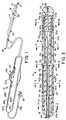
- a handle/actuator in accordance with a preferred embodiment of the invention and an associated steerable electrode cathetercomprise an elongated flexible shaft 10, the handle/actuator 12 and a tip assembly 14 (Fig. 1). As described below, the user manipulates the tip assembly 14 by means of the handle/actuator 12 and control cables which pass through the shaft 10.
- the tip assembly 14comprises a tubular proximal section 15 and a tubular distal section 16 aligned coaxially with the shaft 10 and of approximately the same outer diameter.
- the distal end of the catheterterminates in an electrode cap 17 which is also coaxially aligned with the shaft 10 and sections 15 and 16.
- a threaded collar 19is secured to the distal end of distal section 16 to retain the electrode cap 17 as described further below.
- Shaft 10includes a core 18 (Fig. 3) having a single lumen 20 which extends the length of the shaft from the distal end of the handle/actuator 12. As described in greater detail below, the single-lumen 20 holds four pull cables 32a, b, c and d and four electrode signal wires 34.
- the core 18is enclosed in a flexible outer protective sheath 22.
- the core 18 with its outer protective sheath 22has a predetermined degree of rigidity which depends on the intended use of the catheter.
- the steerable electrode catheter assemblymay be viewed as including mechanical and electrical sub-assemblies.
- the mechanical sub-assemblyis a remote steering system which includes the handle/actuator 12 connected to the four pull cables 32a, 32b, 32c and 32d which run the length of shaft 10 within lumen 20 of core 18.
- the distal ends of the pull cables 32are connected to various points of the tip assembly 14 as described below.
- the pull cables 32translate handle actuator manipulation by the working electrophysiologist through the length of the shaft 10 into single or multi-planar, proximal and/or distal bending movement of the tip assembly 14 as described below.
- Each pull cable 32preferably includes a sheath 33 (shown only in Figs. 9-12).
- the electrical portion of the steerable electrode catheter assemblyincludes three spaced ring-type electrodes 26 along with electrode cap 17.
- the electrodesprovide signal information on heart potentials to remote recording equipment (not shown) used by the electrophysiologist.
- the ring-type electrode contacts 26 and the electrode cap 17are electrically connected to respective signal wires 34.
- the signal wires 34are routed through the length of core 18 through lumen 20, as illustrated in Figs. 3 and 4.
- the signal wires 34are preferably electrically insulated from each other and therefore may all share a single lumen as shown in Figs. 4-8.
- the signal wires 34extend proximally through the handle/actuator 12 to a connector 35 which enables the electrodes 26 and 17 to be easily coupled electrically to the recording equipment (not shown).
- two pull cables 32a and 32care used to control bending of the proximal section 15 within a horizontal plane of orientation as shown diagrammatically in Fig. 2.
- the other two pull cables 32b and 32care used to control bending of the distal section 16 within a vertical plane of orientation.
- the illustrated catheterprovides perpendicular planes of proximal and distal movement
- the relative orientation between these two planesmay vary with different catheter applications and desired tip-shapes and the two planes may form angles between zero degrees and one hundred eighty degrees.
- one catheter tip arrangementfor example a two-dimensional arrangement (where both planes are coplanar) may be bent into a specific shape (such as a spiral) within the single plane of movement. If the first and second planes of orientation of the respective proximal and distal bending movements intersect at ninety degrees (as illustrated in Fig. 2), the resulting catheter tip may be manipulated into several two and three-dimensional shapes including a three-dimensional spiral cone.
- the proximal section 15includes a central lumen 56 (Fig. 5) for passing pull cables 32b and 32d and all of the signal wires 34 from the lumen 20 of core 18 to the distal section 16.
- the proximal section 15also includes two proximal cable lumens 42a and 42c which pass pull cables 32a and 32c from the lumen 20 of the core 18 through the length of the proximal section 15.
- Proximal cable lumens 42b and 42dmay contain respective stiffening wires 43b and 43d to reduce axial twisting of proximal section 15.
- the proximal section 15includes reduced diameter ends 44 and 46 so that the proximal section 15 may snugly nest into appropriately cored recesses of the protective sheath 22 and the distal section 16, respectively.
- Proximal bendingis controlled by the pull cables 32a and 32c. These two cables extend from lumen 20 of core 18 through lumens 42a and 42c in proximal section 15 as shown in Fig. 5. Cables 32a and 32c are attached to each other at the distal end 44 of proximal section 14 as described below.
- the proximal section 15is thermally bonded to the distal end of the protective sheath 22.
- the core 18is shorter in length than the protective sheath so that a transition space 54 is created between the distal end of core 18 and the proximal end of the proximal section 15.
- the transition space 54allows the signal wires 34 and the pull cables 32 to be radially displaced, as discussed below.
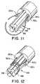
- the pull cables 32a and 32care tied to each other to form a knot 50 across the reduced diameter end 44 of proximal section 15.
- Knot 50preferably lies within the channel-like remains of a proximal cable lumen 42 intersecting the reduced diameter end 44.
- strain relief wire 52is wrapped around both the reduced diameter end 44 and the knot 50 to anchor the ends of the pull cables 32a and 32c to the proximal section 15.
- the knot 50 and the strain relief wire 52are potted in place using an appropriate potting material (not shown) such as an epoxy.
- the strain relief wire 52helps to distribute a portion of the resulting strain, thereby preventing the knot 50 from failing.
- the pull cables 32a and 32care introduced as a single pull cable.
- the two ends of the pull cableare fed into the corresponding proximal cable lumen 42a, 42c and then through the main pull cable lumen 20 of shaft 10 to the handle actuator.
- the resulting loop of pull cable (shown in Fig. 11) formed at the distal end 44 of the proximal section 15is stripped of its sheath, wrapped (coiled) around the reduced diameter end 44 (Fig. 12), and potted into position.
- This embodimenteliminates the need to knot the pull cable ends because the pull cable ends are already attached to each other.
- the cable lumens 42a and 42c through which cables 32a and 32c passare located as close as possible to the circumference of the proximal section 15.
- the distal section 16includes two cable lumens 60b and 60d and a central lumen 62 (Fig. 7). Pull cables 32b and 32d from the central proximal section lumen 56 are routed to the outwardly disposed cable lumens 60b and 60d, respectively, at a point just past the distal end of the proximal section 15.
- the three ring-type electrode contacts 26are embedded within the outside wall portion of the distal section 16. It is preferred that these electrode contacts be embedded so that the outer surface of each contact 26 is flush with the outer wall. These electrode contacts 26 (and others if used) may be positioned anywhere along the entire length of the shaft 10 or the tip assembly 14.
- the signal wires 34which have been routed from the central proximal section lumen 56 into the central lumen 62 of the distal section 16 are directed through respective holes 49 (Fig. 7) to their respective ring-type electrode contacts 26, and connected thereto in a conventional manner, i.e., by soldering or welding.
- Collar 19includes a central lumen 68 and at least two outer cable lumens 70b and 70d (Fig. 8).
- the central lumen 68receives the last remaining electrode signal wire 34, while the cable lumens 70b and 70d direct the pull cables 32b and 32d distally to their anchoring point.
- Pull cables 32b and 32dare tied to each other at a point just past the distal end of the threaded collar 19 to form a knot 72.
- the knot 72is further secured by applying an adhesive, such as an ultra-violet activated adhesive.
- the electrode cap 17includes a hollow threaded recess which engages the external threads of collar 19. Electrode cap 17 includes a central opening 74 which receives the last remaining signal wire 34 of this preferred embodiment.
- the signal wire 34may be electrically connected to the electrode cap 17 by any conventional method, such as soldering or welding.
- proximal and distal bending of the catheterare essentially independent, i.e., bending of the distal section 16 does not cause bending of proximal section 15 (or shaft 10) and vice versa.
- the bending of either section 15 or 16is generally analogous to the bending of a cantilevered beam in the sense that one end of either section (i.e., the proximal end) is fixed while the entire section bends as tension is applied to a cable attached to the opposite end.
- the shaft 10be stiffer than proximal section 15 and that the proximal section 15 be stiffer than the distal section 16.
- the extent to which the stiffness of these various sections must differ to provide independent proximal and distal bendingcan be determined empirically and the example below provides representative values which have been found to work in practice for the configuration illustrated. If independent proximal and distal bending is not desired, the difference in stiffness between the sections is not critical; it is at least theoretically possible that the distal section could be stiffer than the proximal section.
- tension applied to cable 32a or 32ccauses the proximal section 15 to bend horizontally (i.e., in and out of the plane of the paper) about reduced diameter end 46. Because of the hardness differential between the proximal section 15 and shaft 10, the shaft 10 does not bend significantly. There is no tendency of the distal section 16 to bend in this case.
- the distal section 16When tension is applied to one of the cables 32b or 32d, the distal section 16 is bent in a vertical plane (i.e., in the plane of the paper) about the reduced diameter end 44 of proximal section 15. This vertical bending of the distal section occurs regardless of the condition of the proximal section 15. Again, if the differential in hardness between sections 15 and 16 is sufficient, bending of distal section 16 will not cause substantial bending of either proximal section 15 or shaft 10.
- each of the sections 15 and 16is, of course, affected by the length of the section. Representative values of section lengths are also given below.
- Various configurationscan be used to locate and anchor the pull cables within the shaft and the proximal and distal sections of the catheter tip assembly. It is preferable to conduct the pull cables as close as possible to the outer circumference of the section controlled by the cables in order to increase the bending moment. For this reason, the controlling push pull cables for both the proximal and distal sections are directed to outer lumens, i.e., lumens 42a, 42c and lumens 60b, 60d.
- the illustrated constructionhas been found to be an optimal arrangement from the points of view of manufacturing ease and function. Other arrangements, however, can also be used.
- the pull cablescan be conducted through the proximal and distal sections exclusively through outer lumens.
- the wires 34may be conducted through separate lumens, including a single designated outer lumen.
- the cables and wiresalso can be conducted along channels which can be closed by an appropriate covering. It is contemplated that the various tubular sections, including the core and the proximal and distal sections will be extruded.
- Shaft 10may be an extruded polyether block amide of the type sold by Atochem North America, Inc. under the trademark PEBAX (hardness 72-63 Shore D). A typical length is about 110-120 cm with an outer diameter of 2.337 mm (0.092 Inch or 7 French).
- the sheath 22may comprise the same material with an embedded stainless steel braid to enhance stiffness.
- the proximal section 15may also be an extrusion of PEBAX elastomer (hardness 55 Shore D). Alternatively, it may be made of PELLETHANE urethane elastomer supplied by Dow Chemical Company.
- the length of the proximal section 15may be 1.5 - 8.0 cm with the reduced diameter ends 44 and 46 each extending an additional 4 mm.
- the outer diameter of section 15may be 2.337 mm (0.09 inch) with the ends 44 and 46 ground down to a diameter of about 1.702 mm (0.067 inches).
- the stiffening wires 43b and 43dmay be 0.229 mm (0.009 inch) copper wire.
- the distal section 16also an extrusion, may be made of PELLETHANE elastomer (hardness 90 Shore A). Its length may be 2.0 - 8.0 cm.
- the cables 32a, b, c and dmay each comprise a multiplicity of ultra-high molecular weight polyethylene filaments, each forming a bundle with a diameter in the range of 0.076 - 0.102 mm (0.003 - 0.004 inches).
- Sheath 33may be made of polytetrafluoroethylene (TEFLON brand) with an outer diameter of 0.356 mm (0.014 inch) and an inner diameter of 0.254 mm (0.010 inch)
- Collar 19may be a polycarbonate or ABS plastic. It may be bonded to the distal section 16 by an adhesive or by thermal bonding.
- the electrodes 17 and 26may be made of any appropriate electrode contact metal, such as platinum.
- the wires 34are welded to the electrodes 26.
- the distal end of the distal section 16is tapered and the proximal end of the distal section 16 is cored to a diameter of 17.02 mm (0.67 inch).
- the holes 49 for wires 34are formed in the distal section 16 and the section pulled to reduce its diameter so the electrodes rings can be slid into position and the wires 34 threaded through the holes.
- the tapered endis then cut to length and cored to a diameter of 17.02 mm (0.67 inch).
- Both ends of the proximal section 15are ground to a diameter of 17.02 mm (0.67 inch).
- the shaft 10is then cored to a diameter of 17.02 mm (0.67 inch) and out to length.
- Proximal section 15is then inserted into the cored end of shaft 10 and thermally welded.
- the cables 32are conditioned to rid them of "creep" and stretch. This is done by cyclically loading the cables by the application of a specified tensile force. The cables 32 are then threaded through their respective lumens in the shaft 10 and sections 15 and 16.
- Cables 32a and 32care anchored as described above to reduced diameter end 44 of proximal section 15.
- the distal section 16is then secured to the proximal section 15, also by thermal welding.
- the cables 32are threaded through and secured to collar 19.
- One of the wires 34is welded to the electrode cap 17.
- the wireis then threaded into the catheter and the electrode cap 17 screwed onto the collar 19.
- the electrode cap 17 and the collar 19are then inserted into the distal section 16.
- a ring of adhesiveis applied around the edges of the electrodes to provide smooth transitions at the electrodes and to seal the electrodes.
- the assembled catheter with the electrical wires 34 and pull cables 32a, b, c and d extending from its proximal endmay then be attached to the handle/actuator 12 which is described in the following section of the specification.
- the handle/actuator 12applies tension selectively to one of the four pull cables 32a, b, c and d and also routes the electrical wires 34 to the appropriate instruments.
- the handlerequires separate controls for the proximal and distal bending, respectively, and these controls should be easily distinguishable by the surgeon during use. As is customary, the entire handle may be rotated during use to apply a torquing force to the catheter; therefore, the individual controls should be easily accessible when the handle is rotated. All required manipulations should be consistent regardless of the position of the handle or its placement.
- both steering controlsshould be actuable without requiring substantial hand movements and the handle should provide for near simultaneous actuation of both proximal and distal steering.
- the handlemust be able to meet all appropriate environmental and sterility requirements likely to be encountered. Preferably, it provides a mechanical advantage.
- the handleshould be able to hold the tip assembly in a bent or deflected condition until the surgeon actively changes deflection.
- the mechanismshould be able to compensate for stretching of the pull cables likely to be encountered during normal use.
- FIGs. 14-21A handle/actuator assembly in accordance with the preferred embodiments of the invention, is shown in Figs. 14-21.
- the handle configuration shown in these drawingsuses rotational movement to control selectively the tension applied to the horizontal pull cables 32a and 32c, and linear movement to control selectively the tension applied to the vertical pull cables 32b and 32d.
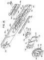
- the handle/actuator 12comprises a housing having a left section 80L and a right section 80R.
- these two sections 80L and 80Rare somewhat semicircular in cross section (Figs. 20-22) and have flat connecting surfaces 82L and 82R which may be secured to each other along a common plane to form a complete housing for handle/actuator 12.
- the outer surfaces 83L and 83R of the handle/actuator 12are contoured to be comfortably held by the user.
- a wheel cavity 84is formed within the right section 80R of the handle/actuator 12.
- the wheel cavity 84includes a planar rear surface 86 which is generally parallel to the flat surface 82R and an arcuate wall section 88 which extends perpendicularly between the planar rear surface 86 and the flat surface 82R.
- the wall section 88terminates at the intersection of the adjacent outer surface 83 of the right handle section 80R and provides a wheel access opening 90R.
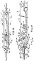
- the wheel cavity 84also includes a central shaft 87 which protrudes perpendicularly from the planar rear surface 86 and extends toward the left section 80L to function as a support for a thumb wheel 92.
- the thumb wheel 92is a generally circular disc having a central bore 94, an integrally formed pulley 96, and upper and lower cable anchors 98.
- the thumb wheel 92is positioned about the shaft 87 so that it may rotate freely within the wheel cavity 84.
- the pulley 96 of the thumb wheel 92is centrally formed about the central bore 94 and operates within a pulley plane which is parallel to the planar rear surface 86.
- a peripheral edge surface 100 of the thumb wheel 92protrudes from the wheel access opening 90 so that the thumb wheel 92 may be rotated by the thumb of the operator's hand which is used to grip the handle 12.
- the peripheral edge surface 100 of the thumb wheel 92is preferably serrated, or otherwise roughened. Different serrations on opposite halves of thumb wheel 92 enable the user to "feel" the position of the thumb wheel.
- the thumb wheel 92includes an indicator of a neutral position wherein, for example, the two pull cables 32a, 32c which are connected to the thumb wheel 92 are both equally tensioned and the corresponding section of the tip assembly 14 is in its relaxed position.
- a neutral position indicatoris provided using a positive detent engagement between the thumb wheel 92 and a portion of the housing 12.
- a detent spring 102is provided within a spring recess 104 formed in the planar rear surface 86 of the wheel cavity 84. A contact portion of the detent spring 102 projects into frictional contact with the adjacent side surface of the thumb wheel 92.
- a detent 108is formed within the side surface 106 of the thumb wheel 92 so that in the neutral position of thumb wheel 92 the detent 108 receives the contact portion of the detent spring 102 resulting in a point of high-friction which provides an indication of the neutral position of the thumb wheel 92.
- a cover plate 110is attached to the flat connecting surface 82R of the right handle section retaining the thumb wheel 92 in its mounted position on the central shaft 87 and within the wheel cavity 84.
- the cover plate 110is preferably made from a rigid material such as metal or hard plastic.
- the cover plate 110includes an opening 112 to receive the central shaft 87.
- An O-ring 114is positioned between the cover plate 110 and the thumb wheel 92.
- the cover plate 110is attached to the right handle section 80R at a proximal secured end 116 by a bolt or screw 117 so that a controlled amount of friction resistance is imparted to the thumb wheel 92 by compressing the O-ring 114.
- Such a rotational resistanceis used to maintain the thumb wheel 92 in a particular angular position and therefore also maintain a particular bend at the tip assembly 14.
- the distal end 118 of the cover plate 110includes two openings 120 to receive two corresponding alignment dowels 122 extending from section 80R.
- the alignment dowels 122are secured to a cable guide 124 which, in turn, is attached to the flat surface 82R.
- the dowels 122are preferably press-fit into the two openings 120.
- the cable guide 124is used to divert the pull cables 32a and 32c from the core 10 to the plane of pulley 96 as described below.
- the cable guide 124has a smooth curved forward surface 125 which prevents contact trauma to the delicate pull cables as they are diverted.
- a gap 126is provided between the cable guide 124 and the end 118 of the cover plate 110.
- the gap 126is sized to receive the two pull cables 32a and 32c and lies within the above-mentioned plane of pulley 96.
- the pulley planeis a prescribed distance from the flat connecting surface 82R of the right handle section 80R.
- a distal opening 128is provided within the distal end of the handle/actuator 12 and is centered along the longitudinal axis of the device (the formation of the forward opening 128 is shared between the right and left sections 80R and 80L).
- the forward opening 128is adapted to snugly receive shaft 10 which is secured within the opening 128 by an appropriate adhesive.
- a strain relief element 129is retained within complementary cavities (not numbered) of sections 80R and 80L.
- a proximal opening 132 centered on the longitudinal axisis also split between the right and left handle sections 80R and 80L.
- the proximal opening 132is adapted to snugly receive an electrical conduit 134 (see Fig. 1) which routes the four electrode signal wires 34 to connector 35 so that the electrodes can be coupled to the monitoring equipment.
- a conventional strain relief element 133is supported within a complementary recess 137 formed in both sections 80R and 80L to reduce the likelihood of damage to the electrode wires caused by bending of the wires.
- the sections 80R and 80Lcontain respective channels 136R and 136L to enable the four pull wires 32 to be anchored at their proper positions within the handle and also to enable the four electrode wires 34 to pass through the entire channel. As shown in Figs. 14 and 15, channel 136R extends the entire length of section 80R whereas channel 136L is formed essentially only in the distal half of the section 80L. When the sections 80R and 80L are assembled, the channels 136R and 136L provide the necessary space for the operating mechanism of the handle. The channels also enable the pull wires 32 to be passed to the appropriate actuator mechanisms and the electrode wires 34 to be passed to the connector 35.
- Channels 136R and 136Lare formed (preferably integrally) within the right and the left sections 80R, 80L, respectively, of the handle/actuator 12. When the right and left handle sections are assembled, the resulting complete channel 136 connects the distal opening 128 to the proximal opening 132.
- the channels 136R, 136Lare not necessarily formed along the longitudinal axis 81, but may be routed to avoid other elements mounted between the two handle sections 80R and 80L.
- the proximal end of the tubular shaft 10terminates near the distal end of the handle/actuator 12 so that the four electrode signal wires 34 and the four pull wires 32 may be distributed as necessary.
- the four electrode signal wires 34are routed through the channel 136 and are electrically connected to the appropriate signal/recorder wires 135 of the electrical conduit 134.
- the pull cablesare separated into horizontal and vertical pull cable pairs 32a, 32c and 32b, 32d, respectively.
- Pull cables 32a and 32care positioned within the gap 126 between the cable guide 124 and cable plate 110, and also between the two alignment dowels 122.
- the two pull cables 32a and 32c which control proximal bending of proximal section 15are connected to the cable anchors 98.
- the cable anchors 98are conventional bolt-type arrangements.
- the cablesare wrapped around the anchors and potted into place using an UV adhesive.
- One pull cable 32a, which is connected to the upper cable anchor 98,is positioned within the groove of the pulley 96 so that it rides over the pulley 96 and contacts the upper of the two alignment dowels 122 when pulled taut.
- the other pull cable 32cis connected to the lower cable anchor 98 and is positioned within the pulley groove so that it rides below the pulley 96 and contacts the lower alignment dowel 122 when taut.
- the left section 80L of the handle/actuator 12includes a substantially hollow interior cavity which is shaped to cover the above-described elements.
- the left section 80Lsupports part of the mechanism for selectively tensioning each of the two vertical pull cables 32b and 32d.
- the left handle section 80Lincludes a wheel access opening 90L similar in shape to the wheel access opening 90R of the right handle section 80R. It also includes an elongated slot 138 in its side surface.
- a slider 140is provided with a neck portion 142 which fits snugly within the slot 138.
- the slider 140includes an upper edge 144, a forward cable anchor 146, a rear cable anchor 148, and a friction pad 150.
- a slider grip 152is attached to the neck portion 142 of the slider 140 and positioned externally of the handle/actuator 12.
- the slider grip 152is preferably ergonometrically shaped to be comfortably controlled by the user.
- Preload pads 154are positioned between the outer surface 83L of the left handle section 80L and the slider grip 152.
- the friction pad 150functions to provide constant friction during sliding movement of the slider 140 and the slider grip 152 so that any desired position is maintained until the friction of the friction pad 150 is overcome, e.g., by physically repositioning the slider grip 152.
- a dust seal 156(Figs. 15 and 17-19) having an elongated slit 158 and preferably made from latex is bonded along the slot 138 within the left handle section 80L.
- the neck portion 142 of the slider 140protrudes through the slit 158 of the dust seal 156 so that the slit only separates adjacent to the neck portion 142. Otherwise, the slit 158 remains "closed” and functions as an effective barrier preventing dust, hair and other contaminants from entering the actuator/handle 12.
- the left handle section 80Lincludes a slider chamber 160 (Figs. 20-22) which aligns with and is centered about the slot 138.
- the slider chamber 160receives the slider 140 and includes an upper contact surface 162 and a friction surface 163.
- a center pin 164is affixed along the upper contact surface 162.
- the center pin 164is parallel to the central shaft 87 and is adapted to engage a detent 166 (Fig. 14) in the upper edge 144 of the slider 140. At a prescribed point between the stop positions, the detent will engage the center pin 164 and thus indicate a neutral sliding position for the vertical pull cable pair.
- the friction pad 150 of the slider 140contacts the friction surface 163 of the slider chamber 160 and generates resistance to the movement of the slider 140. This resistance further helps maintain a desired position of the slider 140 against the tension force of a taut pull cable 32b or 32d.
- the two pull cables 32b and 32d of the vertical pull cable pairare attached to the two cable anchors 146, 148 of the slider 140.
- Pull cable 32bis directly attached to the forward cable anchor 146 and becomes taut when the slider grip 152 (and the slider 140) is moved along the longitudinal axis 81 towards the proximal end of the handle/actuator 12.
- the other pull cable 32dis guided by a return pulley 168 prior to being attached to the rear cable anchor 148.
- the return pulley 168is attached to a pulley axle 170 which is supported in a bore (not shown) in the flat surface 82R of the right handle section 80R and a bore in a pulley cover 174, as shown in Fig. 14.
- the pulley cover 174is either formed integrally with the right handle section 80R or otherwise attached to the flat surface 82R at a position which is behind the slider 140 and along the longitudinal axis 81R.
- the groove (not shown) of the return pulley 168lies in a return pulley plane which is parallel to the previously described pulley plane of pulley 96 but lies further from the flat surface 82R than does the pulley plane of pulley 96.
- the return pulley planeis in alignment with the rear cable anchor 148 of the slider 140.
- the handle/actuator in accordance with the preferred embodiment of the inventionhas been described for use with a steerable catheter having independent proximal and distal bending. While the invention is of particular utility with such a catheter, a handle/actuator according to the invention would also have utility with a four-way steerable catheter (for example) wherein the same section of the catheter can be deflected in different planes. It is even conceivable that the principals of the invention may have utility in controlling bending of one section in one plane wherein one pull cable would be connected to a slider or thumb wheel and the other pull cable connected to a slider or thumb wheel. This would enable the physician to distinguish tactily between the two pull cables.
- the left and right handle sections 80R and 80L, the thumb wheel 92 and the slide grip 152are made of polyurethane, polycarbonate, or ABS plastic.
- the return pulley 168, the slider 140, and the cable guide 124are made from natural derlin plastic.
- the pulley cover 174is made from ABS plastic.
- the detent spring 102, the cable anchors 98, 146 and 148are made from stainless steel.
- the lip seal 156is made from latex plastic.
- the preload pad 154is made from a medium silicone sponge of the type manufactured by CHR Industries of New Haven, CT. (Part No. 200A), laminated to a contact surface made from UHMW polyethylene tape available from McMaster-Carr. (Part No. 76445A14).
- the friction pad 150is made from silicone cord stock having a durometer value of 60 and available from Greene Rubber Co.
Landscapes
- Health & Medical Sciences (AREA)
- Life Sciences & Earth Sciences (AREA)
- Engineering & Computer Science (AREA)
- Animal Behavior & Ethology (AREA)
- Veterinary Medicine (AREA)
- Public Health (AREA)
- Biomedical Technology (AREA)
- Heart & Thoracic Surgery (AREA)
- General Health & Medical Sciences (AREA)
- Anesthesiology (AREA)
- Pulmonology (AREA)
- Biophysics (AREA)
- Hematology (AREA)
- Surgery (AREA)
- Mechanical Engineering (AREA)
- Physics & Mathematics (AREA)
- Plasma & Fusion (AREA)
- Nuclear Medicine, Radiotherapy & Molecular Imaging (AREA)
- Otolaryngology (AREA)
- Cardiology (AREA)
- Medical Informatics (AREA)
- Molecular Biology (AREA)
- Media Introduction/Drainage Providing Device (AREA)
Abstract
Description
Claims (16)
- A handle/actuator (12) for use with a steerablecatheter having a tip assembly (14)and at least twopull cables (32a - 32d) for bending said tip assembly(14), the handle/actuator (12) comprising:a housing (12),a wheel (92) rotatably supported in said housing (12),at least a first of said pull cables (32a, c)beinganchored to said wheel (92) such that manualapplication of a first force to said wheel (92) causesrotation of said wheel (92) in one direction to applytension to said pull cable (32a, c), at least aportion of said wheel (92) being accessible from theexterior of said housing (12) so that said wheel (92)can be rotated manually,a slider (140) slidably mounted in said housing (12),at least a second of said pull cables (32b, d) beinganchored to said slider (140) such that manualapplication of a second force to said slider (140)causes linear movement of said slider (140) in onedirection relative to said housing (12) to applytension to said second cable (32b, d), andmeans (152) exterior of said housing (12) for movingsaid slider (140).
- A handle/actuator (12) according to claim 1,including:means (102, 108) associated with said wheel (92) forindicating when said wheel (92) is rotated to aposition in which substantially no tension is appliedto said one cable (32a, c);means (164) associated with said slider (140) forindicating when said slider (140) is in a position inwhich substantially no tension is supplied to saidsecond cable (32b, d);a pulley (96) attached to said wheel (92), said onecable (32a, c) passing over at least a section of saidpulley (96);means (110, 114) cooperating with said wheel (92) formaintaining tension on said one cable (32b, d) whensaid first force is removed from said wheel (92); andmeans (150) cooperating with said slider (140) formaintaining tension on said second cable (32b, d) whensaid second force is removed from said slider (140).
- A handle/actuator (12) according to claim 1 or 2,whereinfirst and second pull cables (32a, c) are anchored tosaid wheel (92) such that clockwise rotation of said wheel (92) applies tension to said first pull cable(32a) and counter-clockwise rotation of said wheelapplies tension to said second pull cable (32c),said slider (140) is mounted in said housing (12) forlinear movement in response to a second manual force,third and fourth pull cables (32b, d) are anchored tosaid slider (140) such that linear movement of saidslider (140) in one direction applies tension to saidthird cable (32b) and longitudinal movement of saidslider (140) in a direction opposite said onedirection applies tension to said fourth cable (32d).
- A handle/actuator (12) according to claim 3 asdependent on claim 1 or 2 and including:a pulley (96) mounted for rotation within said housing(12) and spaced from said slider (140), said fourthpull cable (32d) extending around said pulley (96),said pulley (96) being attached to said wheel (92),said first and second cables (32a, c) passing over atleast a section of said pulley (96), saidhandle/actuator (12) further including means (110,114) cooperating with said wheel (92) for maintainingthe angular position of said wheel (92) when saidfirst manual force is removed from said wheel (92),and means (150) cooperating with said slider (140) formaintaining the linear position of said slider (140),when said second manual force is removed from saidslider (140).
- A handle/actuator according to claim 3 as dependent onclaim 1 or 2 and including:means (102, 108) associated with said wheel (92) forindicating when said wheel (92) is rotated to aposition in which the tension applied to said firstand second cables (32a, c) is substantially equal, andmeans (150) associated with said slider for indicatingwhen the tension applied to said third and fourthcables (32b, d) is substantially equal;means (110, 114) cooperating with said wheel (92) formaintaining the angular position of said wheel (92)when said first manual force is removed from saidwheel (92); andmeans (150) cooperating with said slider (140) formaintaining the linear position of said slider (140)when said second manual force is removed from saidslider (140).
- A handle/actuator (12) according to any of claims 3 to5 in combination with a steerable catheter, thecombination comprising:an elongated flexible shaft (10) having a lumen (20)running the length of the shaft (10), and a flexibletip assembly (14) connected to the distal end of saidshaft (10), said pull cables (32) passing through saidshaft (10) to said tip assembly (14), andsaid housing (12) being connected to the proximal end(15) of said shaft 10;means (50, 52) for securing the distal ends of saidfirst and second pull cables (32a, c) at a firstlocation along said tip assembly so that tensionapplied to one of said first and second cables (32a,c) will cause a first section (16) of said flexibletip assembly (14) to bend; andmeans (72) for securing the distal ends of said thirdand fourth pull cables (32b, d) at a second locationalong said tip assembly (14) axially displaced fromsaid first location so that tension applied to one ofsaid third and fourth cables (32b, d) will cause asecond section (15) of said tip assembly (14)displaced axially from said first section (16) tobend.
- A combination according to claim 6, further includingmeans (152) exterior of said housing for moving saidslider (140).
- A combination according to claim 6 or 7, wherein saidfirst and second sections (15, 16) are bent indifferent planes.
- A combination according to claim 8, wherein said firstplane and said second plane are coplanar or perpendicular.
- A combination according to any of claims 6 to 9,wherein the stiffness and length of each of said firstand second sections (15, 16) are selected to provide apredetermined curve configuration of said tip assembly(14) when said first section (16) or second section(15) is bent.
- A combination according to claim 10, one of said first(16) and second (15) sections being a distal section,the other a proximal section, wherein said shaft (10)is sufficiently stiffer than said proximal section(15) so that the shaft (10) does not bendsubstantially when said proximal section (15) is bent,and wherein said proximal section (15) is sufficientlystiffer than said distal section (16) so that theproximal section (15) does not bend substantially whensaid distal section (16) is bent.
- A combination according to claim 10 or 11, whereineach of said means for bending (50, 72) bends said tipassembly (14) in at least two opposite directions.
- A combination according to any of claims 8 to 12,wherein said first and second planes form an anglebetween them of approximately ninety degrees.
- A combination according to any of claims 6 to 13,wherein each of said first and second sections (15,16) includes a central lumen (56, 62) and at least two outer lumens (42), and wherein said first and secondpull cables (32a, c) are positioned in respectiveouter lumens (42) of said first section (16) and saidthird and fourth pull cables (32b, d) are positionedin respective outer lumens (42) of said second section(15), wherein said first and second pull cables (32a,c) are anchored at the distal end of said firstsection (16) and said third and fourth pull cables(32b, d) are anchored at the distal end of said secondsection (15).
- A combination of any of claims 6 to 14, wherein saidcatheter is an electrocardial catheter, comprising atleast one electrode (26) mounted on said tip assembly(14).
- A combination according to any of claims 6 to 15,wherein said cables (32) comprise ultra-high molecularweight polyethylene enveloped by a polyfluoroethylenesheath.
Applications Claiming Priority (5)
| Application Number | Priority Date | Filing Date | Title |
|---|---|---|---|
| US07/987,750US5383852A (en) | 1992-12-04 | 1992-12-04 | Catheter with independent proximal and distal control |
| US987750 | 1992-12-04 | ||
| US08/084,549US5462527A (en) | 1993-06-29 | 1993-06-29 | Actuator for use with steerable catheter |
| US84549 | 1993-06-29 | ||
| EP19930119537EP0605796B1 (en) | 1992-12-04 | 1993-12-03 | Catheter with independent proximal and distal control |
Related Parent Applications (1)
| Application Number | Title | Priority Date | Filing Date |
|---|---|---|---|
| EP19930119537DivisionEP0605796B1 (en) | 1992-12-04 | 1993-12-03 | Catheter with independent proximal and distal control |
Publications (3)
| Publication Number | Publication Date |
|---|---|
| EP1046406A2true EP1046406A2 (en) | 2000-10-25 |
| EP1046406A3 EP1046406A3 (en) | 2001-10-24 |
| EP1046406B1 EP1046406B1 (en) | 2003-10-15 |
Family
ID=26771117
Family Applications (2)
| Application Number | Title | Priority Date | Filing Date |
|---|---|---|---|
| EP00114145AExpired - LifetimeEP1046406B1 (en) | 1992-12-04 | 1993-12-03 | Actuator for use with a catheter with independent proximal and distal control |
| EP19930119537Expired - LifetimeEP0605796B1 (en) | 1992-12-04 | 1993-12-03 | Catheter with independent proximal and distal control |
Family Applications After (1)
| Application Number | Title | Priority Date | Filing Date |
|---|---|---|---|
| EP19930119537Expired - LifetimeEP0605796B1 (en) | 1992-12-04 | 1993-12-03 | Catheter with independent proximal and distal control |
Country Status (4)
| Country | Link |
|---|---|
| EP (2) | EP1046406B1 (en) |
| JP (1) | JP3526598B2 (en) |
| CA (1) | CA2110668A1 (en) |
| DE (2) | DE69333140T2 (en) |
Cited By (19)
| Publication number | Priority date | Publication date | Assignee | Title |
|---|---|---|---|---|
| WO2002089891A3 (en)* | 2001-05-04 | 2003-03-20 | Cardiac Pacemakers Inc | Self-locking handle for steering a single or multiple-profile catheter |
| EP1245245A3 (en)* | 2001-03-30 | 2003-03-26 | Biosense Webster, Inc. | Steerable catheter with a control handle having a pulley mechanism |
| WO2002089890A3 (en)* | 2001-05-02 | 2003-03-27 | Cardiac Pacemakers Inc | Dual-profile steerable catheter |
| EP1389478A1 (en)* | 2002-08-16 | 2004-02-18 | Cryocor, Inc. | Catheter having articulation system made from two different materials |
| WO2003082395A3 (en)* | 2002-03-22 | 2004-03-04 | Scimed Life Systems Inc | Drainage catheter with visual indicator and/or lock system |
| EP1286721A4 (en)* | 2000-05-19 | 2006-12-06 | Conmed Endoscopic Technologies | Steerable biliary catheter |
| EP1803480A3 (en)* | 2005-12-29 | 2008-03-05 | Biosense Webster, Inc. | Deflectable catheter with a high modulus fiber puller element |
| FR2917601A1 (en)* | 2007-06-25 | 2008-12-26 | Stentys S A S Soc Par Actions | DEVICE FOR CONTROLLING A CATHETER |
| FR2917602A1 (en)* | 2007-06-25 | 2008-12-26 | Stentys S A S Soc Par Actions | Catheter controlling device, has bar arranged in place of groove such that pinions are gripped with or disengaged from bar on one actuating part that is matched to sufficient stent deployment to immobilize stent with respect to passage |
| WO2009094511A1 (en) | 2008-01-24 | 2009-07-30 | Boston Scientific Scimed, Inc. | Structure for use as part of a medical device |
| WO2012040442A1 (en)* | 2010-09-22 | 2012-03-29 | Johns Hopkins University | Cable-driven morphable manipulator |
| CN102688090A (en)* | 2012-04-29 | 2012-09-26 | 殷跃辉 | Bidirectionally controllable saline-perfusion renal artery radiofrequency ablation catheter |
| US8790250B2 (en) | 2008-12-10 | 2014-07-29 | Ambu A/S | Endoscope bending section control mechanism |
| CN107550562A (en)* | 2017-09-30 | 2018-01-09 | 常州市延陵电子设备有限公司 | Procedures electrode distal drainage device and procedures electrode apparatus |
| US11166627B2 (en) | 2018-01-26 | 2021-11-09 | Ambu A/S | Method for fixation of a wire portion of an endoscope, and an endoscope |
| EP3972476A1 (en)* | 2019-05-21 | 2022-03-30 | Koninklijke Philips N.V. | Pull-cable management for steerable catheter |
| US11291355B2 (en) | 2018-01-19 | 2022-04-05 | Ambu A/S | Method for fixation of a wire portion of an endoscope, and an endoscope |
| WO2023139482A1 (en)* | 2022-01-18 | 2023-07-27 | Neuwave Medical, Inc. | Steerable sheath and adjustable scope attachment |
| EP4437930A1 (en)* | 2023-03-27 | 2024-10-02 | Ambu A/S | Endoscope having a media tube |
Families Citing this family (67)
| Publication number | Priority date | Publication date | Assignee | Title |
|---|---|---|---|---|
| US5820591A (en)* | 1990-02-02 | 1998-10-13 | E. P. Technologies, Inc. | Assemblies for creating compound curves in distal catheter regions |
| US6413234B1 (en) | 1990-02-02 | 2002-07-02 | Ep Technologies, Inc. | Assemblies for creating compound curves in distal catheter regions |
| US5611777A (en)* | 1993-05-14 | 1997-03-18 | C.R. Bard, Inc. | Steerable electrode catheter |
| US5715817A (en)* | 1993-06-29 | 1998-02-10 | C.R. Bard, Inc. | Bidirectional steering catheter |
| EP0738498A1 (en)* | 1995-04-18 | 1996-10-23 | Machida Endoscope Co., Ltd | Surgical adhesive sprayer |
| US5752912A (en)* | 1995-06-26 | 1998-05-19 | Asahi Kogaku Kogyo Kabushiki Kaisha | Manipulator for flexible portion of an endoscope |
| US5755760A (en)* | 1996-03-11 | 1998-05-26 | Medtronic, Inc. | Deflectable catheter |
| US6198974B1 (en)* | 1998-08-14 | 2001-03-06 | Cordis Webster, Inc. | Bi-directional steerable catheter |
| US6374476B1 (en)* | 1999-03-03 | 2002-04-23 | Codris Webster, Inc. | Method for making a catheter tip section |
| WO2000076570A2 (en)* | 1999-06-15 | 2000-12-21 | Cryocath Technologies, Inc. | Steerable catheter |
| US6783510B1 (en)* | 1999-07-08 | 2004-08-31 | C.R. Bard, Inc. | Steerable catheter |
| US6332881B1 (en)* | 1999-09-01 | 2001-12-25 | Cardima, Inc. | Surgical ablation tool |
| JP2005532832A (en)* | 2001-09-24 | 2005-11-04 | ノヴォスト コーポレイション | Method and apparatus using ionizing radiation for the treatment of arrhythmias |
| US7604611B2 (en) | 2001-10-19 | 2009-10-20 | C.R. Bard, Inc. | Handle thumb wheel mechanism which maintains holding forces when sterilized and when engaged |
| US20050165366A1 (en) | 2004-01-28 | 2005-07-28 | Brustad John R. | Medical tubing having variable characteristics and method of making same |
| US20050004515A1 (en) | 2002-11-15 | 2005-01-06 | Hart Charles C. | Steerable kink resistant sheath |
| US8529719B2 (en) | 2002-11-15 | 2013-09-10 | Applied Medical Resources Corporation | Method of making medical tubing having variable characteristics using thermal winding |
| CA2523270A1 (en)* | 2003-04-25 | 2004-11-11 | Applied Medical Resources Corporation | Steerable kink-resistant sheath |
| US7374553B2 (en)* | 2004-06-24 | 2008-05-20 | Cryocor, Inc. | System for bi-directionally controlling the cryo-tip of a cryoablation catheter |
| US8376990B2 (en) | 2005-05-19 | 2013-02-19 | Biosense Webster, Inc. | Steerable catheter with distal tip orientation sheaths |
| US8968379B2 (en) | 2005-09-02 | 2015-03-03 | Medtronic Vascular, Inc. | Stent delivery system with multiple evenly spaced pullwires |
| US20070156114A1 (en)* | 2005-12-29 | 2007-07-05 | Worley Seth J | Deflectable catheter with a flexibly attached tip section |
| CA2676119C (en) | 2007-01-29 | 2021-01-19 | Simon Fraser University | Transvascular nerve stimulation apparatus and methods |
| US8162934B2 (en)* | 2007-12-21 | 2012-04-24 | St. Jude Medical, Atrial Fibrillation Division, Inc. | Medical catheter assembly with deflection pull ring and distal tip interlock |
| US8353902B2 (en) | 2008-01-31 | 2013-01-15 | Vivant Medical, Inc. | Articulating ablation device and method |
| US8676290B2 (en)* | 2010-05-11 | 2014-03-18 | St. Jude Medical, Atrial Fibrillation Division, Inc. | Multi-directional catheter control handle |
| JP2010162300A (en)* | 2009-01-14 | 2010-07-29 | Vivant Medical Inc | Articulating ablation device and method |
| US9326872B2 (en)* | 2010-08-17 | 2016-05-03 | W. L. Gore & Associates, Inc. | Forced deployment sequence handle assembly with independent actuating mechanism |
| WO2012088564A1 (en)* | 2010-12-27 | 2012-07-05 | Cathrx Ltd | A modular catheter |
| US20130018306A1 (en) | 2011-07-13 | 2013-01-17 | Doron Moshe Ludwin | System for indicating catheter deflection |
| US9101269B2 (en) | 2011-12-15 | 2015-08-11 | Biosense Webster (Israel), Ltd. | Self-holding medical device control handle with cam actuated clutch mechanism |
| US9821143B2 (en) | 2011-12-15 | 2017-11-21 | Imricor Medical Systems, Inc. | Steerable sheath including elastomeric member |
| US20140135745A1 (en) | 2011-12-15 | 2014-05-15 | Imricor Medical Systems, Inc. | Mri compatible handle and steerable sheath |
| US9757538B2 (en) | 2011-12-15 | 2017-09-12 | Imricor Medical Systems, Inc. | MRI compatible control handle for steerable sheath with audible, tactile and/or visual means |
| IN2014MN01970A (en) | 2012-03-05 | 2015-07-03 | Univ Fraser Simon | |
| JP2013192691A (en)* | 2012-03-19 | 2013-09-30 | Japan Lifeline Co Ltd | Medical tube control handle and medical tube introducing device |
| KR101351822B1 (en)* | 2012-04-17 | 2014-01-15 | 김희진 | Catheter |
| EP2863987B1 (en) | 2012-06-21 | 2023-08-02 | Lungpacer Medical Inc. | Transvascular diaphragm pacing systems |
| DE102012108076A1 (en) | 2012-08-31 | 2014-03-06 | Karl Storz Gmbh & Co. Kg | Shaft for a flexible endoscope or a flexible endoscopic instrument |
| US9095682B2 (en)* | 2013-04-30 | 2015-08-04 | St. Jude Medical Luxembourg Holding S.À.R.L. | Control handles for catheters |
| WO2014182855A1 (en)* | 2013-05-07 | 2014-11-13 | St. Jude Medical, Atrial Fibrillation Division, Inc. | Steering actuator for deflectable catheter |
| CN105873630B (en) | 2013-11-22 | 2020-01-03 | 隆佩瑟尔医疗公司 | Device and method for assisted respiration by transvascular nerve stimulation |
| AU2015208640B2 (en) | 2014-01-21 | 2020-02-20 | Lungpacer Medical Inc. | Systems and related methods for optimization of multi-electrode nerve pacing |
| CN113558821B (en)* | 2016-10-11 | 2024-08-23 | 沃卡尔医药有限公司 | Devices and methods for delivering implants through a catheter |
| US10786651B2 (en) | 2017-03-07 | 2020-09-29 | Talon Medical, LLC | Steerable guide catheter |
| US10293164B2 (en) | 2017-05-26 | 2019-05-21 | Lungpacer Medical Inc. | Apparatus and methods for assisted breathing by transvascular nerve stimulation |
| CN111163834A (en) | 2017-06-30 | 2020-05-15 | 隆佩瑟尔医疗公司 | Device for preventing, reducing and/or treating cognitive impairment |
| US10195429B1 (en) | 2017-08-02 | 2019-02-05 | Lungpacer Medical Inc. | Systems and methods for intravascular catheter positioning and/or nerve stimulation |
| US10940308B2 (en) | 2017-08-04 | 2021-03-09 | Lungpacer Medical Inc. | Systems and methods for trans-esophageal sympathetic ganglion recruitment |
| EP3478150B1 (en)* | 2017-09-20 | 2022-12-28 | Bio-Medical Engineering (HK) Limited | Endoscopic system |
| US20190175908A1 (en) | 2017-12-11 | 2019-06-13 | Lungpacer Medical Inc. | Systems and methods for strengthening a respiratory muscle |
| JP7027917B2 (en)* | 2018-01-31 | 2022-03-02 | 住友ベークライト株式会社 | catheter |
| JP7043858B2 (en)* | 2018-01-31 | 2022-03-30 | 住友ベークライト株式会社 | Medical equipment |
| EP4548964A1 (en) | 2018-11-08 | 2025-05-07 | Lungpacer Medical Inc. | Stimulation systems and related user interfaces |
| US20200170659A1 (en)* | 2018-12-04 | 2020-06-04 | Acclarent, Inc. | Bi-directional articulating surgical shaver |
| CN111437065A (en)* | 2019-01-17 | 2020-07-24 | TauPNU医疗有限公司 | Position-adjustable tricuspid valve backflow surgical instrument |
| EP3695871B1 (en)* | 2019-02-18 | 2024-04-10 | Creganna Unlimited Company | Shaft for a catheter and fabrication method |
| CN109999320B (en)* | 2019-04-30 | 2020-12-29 | 清华大学 | Catheter pusher device and method for vascular interventional procedures |
| WO2020232333A1 (en) | 2019-05-16 | 2020-11-19 | Lungpacer Medical Inc. | Systems and methods for sensing and stimulation |
| WO2020252037A1 (en) | 2019-06-12 | 2020-12-17 | Lungpacer Medical Inc. | Circuitry for medical stimulation systems |
| US11471650B2 (en) | 2019-09-20 | 2022-10-18 | Biosense Webster (Israel) Ltd. | Mechanism for manipulating a puller wire |
| US11964114B2 (en)* | 2020-05-22 | 2024-04-23 | Acclarent, Inc. | Shaft deflection control assembly for ENT guide instrument |
| WO2022137505A1 (en)* | 2020-12-25 | 2022-06-30 | 日本ライフライン株式会社 | Electrode catheter |
| US20240382717A1 (en)* | 2021-09-23 | 2024-11-21 | W Endoluminal Robotics Ltd. | Steerable tubular assembly for bronchoscopic procedures |
| US20250186741A1 (en)* | 2022-02-28 | 2025-06-12 | Canon Kabushiki Kaisha | Medical device, catheter kit, and catheter case |
| DE102022107662A1 (en) | 2022-03-30 | 2023-10-05 | Olympus Winter & Ibe Gmbh | Albarran and shaft for an Albarran |
| CN117379229A (en)* | 2022-07-05 | 2024-01-12 | 上海微创心通医疗科技有限公司 | Controlled bending pipe and conveying device |
Family Cites Families (8)
| Publication number | Priority date | Publication date | Assignee | Title |
|---|---|---|---|---|
| US3552384A (en)* | 1967-07-03 | 1971-01-05 | American Hospital Supply Corp | Controllable tip guide body and catheter |
| CA1222670A (en)* | 1983-04-29 | 1987-06-09 | Walter P. Siegmund | Method and apparatus for deflecting the tip of an endoscope |
| US4586923A (en)* | 1984-06-25 | 1986-05-06 | Cordis Corporation | Curving tip catheter |
| IT1235460B (en)* | 1987-07-31 | 1992-07-30 | Confida Spa | FLEXIBLE ENDOSCOPE. |
| DE69122853T2 (en)* | 1990-02-02 | 1997-10-09 | Ep Technologies, Inc., Sunnyvale, Calif. | STEERING MECHANISM FOR CATHETER |
| JP2987452B2 (en)* | 1990-05-17 | 1999-12-06 | オリンパス光学工業株式会社 | Endoscope |
| US5125896A (en) | 1990-10-10 | 1992-06-30 | C. R. Bard, Inc. | Steerable electrode catheter |
| AU660444B2 (en)* | 1991-02-15 | 1995-06-29 | Ingemar H. Lundquist | Torquable catheter and method |
- 1993
- 1993-12-03JPJP30439293Apatent/JP3526598B2/ennot_activeExpired - Lifetime
- 1993-12-03CACA 2110668patent/CA2110668A1/ennot_activeAbandoned
- 1993-12-03DEDE1993633140patent/DE69333140T2/ennot_activeExpired - Lifetime
- 1993-12-03DEDE1993633256patent/DE69333256T2/ennot_activeExpired - Lifetime
- 1993-12-03EPEP00114145Apatent/EP1046406B1/ennot_activeExpired - Lifetime
- 1993-12-03EPEP19930119537patent/EP0605796B1/ennot_activeExpired - Lifetime
Cited By (34)
| Publication number | Priority date | Publication date | Assignee | Title |
|---|---|---|---|---|
| EP1286721A4 (en)* | 2000-05-19 | 2006-12-06 | Conmed Endoscopic Technologies | Steerable biliary catheter |
| EP1245245A3 (en)* | 2001-03-30 | 2003-03-26 | Biosense Webster, Inc. | Steerable catheter with a control handle having a pulley mechanism |
| US6976987B2 (en) | 2001-05-02 | 2005-12-20 | Cardiac Pacemakers, Inc. | Dual-profile steerable catheter |
| WO2002089890A3 (en)* | 2001-05-02 | 2003-03-27 | Cardiac Pacemakers Inc | Dual-profile steerable catheter |
| US6610058B2 (en) | 2001-05-02 | 2003-08-26 | Cardiac Pacemakers, Inc. | Dual-profile steerable catheter |
| US6652506B2 (en) | 2001-05-04 | 2003-11-25 | Cardiac Pacemakers, Inc. | Self-locking handle for steering a single or multiple-profile catheter |
| WO2002089891A3 (en)* | 2001-05-04 | 2003-03-20 | Cardiac Pacemakers Inc | Self-locking handle for steering a single or multiple-profile catheter |
| US7192415B2 (en) | 2002-03-22 | 2007-03-20 | Scimed Life Systems, Inc. | Drainage catheter with visual indicator and/or lock system |
| US7351222B2 (en) | 2002-03-22 | 2008-04-01 | Scimed Life Systems, Inc. | Drainage catheter with visual indicator and/or lock system |
| WO2003082395A3 (en)* | 2002-03-22 | 2004-03-04 | Scimed Life Systems Inc | Drainage catheter with visual indicator and/or lock system |
| EP1389478A1 (en)* | 2002-08-16 | 2004-02-18 | Cryocor, Inc. | Catheter having articulation system made from two different materials |
| US8540696B2 (en) | 2005-12-29 | 2013-09-24 | Biosense Webster, Inc. | Deflectable catheter with a high modulus fiber puller element |
| EP1803480A3 (en)* | 2005-12-29 | 2008-03-05 | Biosense Webster, Inc. | Deflectable catheter with a high modulus fiber puller element |
| US9662473B2 (en) | 2005-12-29 | 2017-05-30 | Biosense Webster, Inc. | Deflectable catheter with a high modulus fiber puller element |
| FR2917601A1 (en)* | 2007-06-25 | 2008-12-26 | Stentys S A S Soc Par Actions | DEVICE FOR CONTROLLING A CATHETER |
| WO2009001309A1 (en)* | 2007-06-25 | 2008-12-31 | Stentys S.A.S. | Device for controlling a catheter |
| FR2917602A1 (en)* | 2007-06-25 | 2008-12-26 | Stentys S A S Soc Par Actions | Catheter controlling device, has bar arranged in place of groove such that pinions are gripped with or disengaged from bar on one actuating part that is matched to sufficient stent deployment to immobilize stent with respect to passage |
| WO2009094511A1 (en) | 2008-01-24 | 2009-07-30 | Boston Scientific Scimed, Inc. | Structure for use as part of a medical device |
| US9462932B2 (en) | 2008-01-24 | 2016-10-11 | Boston Scientific Scimed, Inc. | Structure for use as part of a medical device |
| US10149605B2 (en) | 2008-12-10 | 2018-12-11 | Ambu A/S | Endoscope bending section control mechanism |
| US10624529B2 (en) | 2008-12-10 | 2020-04-21 | Ambu A/S | Endoscope bending section control mechanism |
| US8790250B2 (en) | 2008-12-10 | 2014-07-29 | Ambu A/S | Endoscope bending section control mechanism |
| US10165931B2 (en) | 2008-12-10 | 2019-01-01 | Ambu A/S | Endoscope bending section control mechanism |
| US9737687B2 (en) | 2010-09-22 | 2017-08-22 | The Johns Hopkins University | Cable-driven morphable manipulator |
| WO2012040442A1 (en)* | 2010-09-22 | 2012-03-29 | Johns Hopkins University | Cable-driven morphable manipulator |
| CN102688090A (en)* | 2012-04-29 | 2012-09-26 | 殷跃辉 | Bidirectionally controllable saline-perfusion renal artery radiofrequency ablation catheter |
| CN107550562A (en)* | 2017-09-30 | 2018-01-09 | 常州市延陵电子设备有限公司 | Procedures electrode distal drainage device and procedures electrode apparatus |
| US11291355B2 (en) | 2018-01-19 | 2022-04-05 | Ambu A/S | Method for fixation of a wire portion of an endoscope, and an endoscope |
| US11832792B2 (en) | 2018-01-19 | 2023-12-05 | Ambu A/S | Method for fixation of a wire portion of an endoscope, and an endoscope |
| US11166627B2 (en) | 2018-01-26 | 2021-11-09 | Ambu A/S | Method for fixation of a wire portion of an endoscope, and an endoscope |
| EP3972476A1 (en)* | 2019-05-21 | 2022-03-30 | Koninklijke Philips N.V. | Pull-cable management for steerable catheter |
| US12295786B2 (en) | 2019-05-21 | 2025-05-13 | Koninklijke Philips N.V. | Pull-cable management for steerable catheter |
| WO2023139482A1 (en)* | 2022-01-18 | 2023-07-27 | Neuwave Medical, Inc. | Steerable sheath and adjustable scope attachment |
| EP4437930A1 (en)* | 2023-03-27 | 2024-10-02 | Ambu A/S | Endoscope having a media tube |
Also Published As
| Publication number | Publication date |
|---|---|
| CA2110668A1 (en) | 1994-06-05 |
| EP1046406B1 (en) | 2003-10-15 |
| DE69333256D1 (en) | 2003-11-20 |
| EP0605796A2 (en) | 1994-07-13 |
| EP0605796A3 (en) | 1997-01-29 |
| DE69333140T2 (en) | 2004-06-09 |
| JP3526598B2 (en) | 2004-05-17 |
| EP1046406A3 (en) | 2001-10-24 |
| DE69333256T2 (en) | 2004-07-22 |
| DE69333140D1 (en) | 2003-09-18 |
| JPH06292728A (en) | 1994-10-21 |
| EP0605796B1 (en) | 2003-08-13 |
Similar Documents
| Publication | Publication Date | Title |
|---|---|---|
| EP1046406B1 (en) | Actuator for use with a catheter with independent proximal and distal control | |
| US5462527A (en) | Actuator for use with steerable catheter | |
| US5383852A (en) | Catheter with independent proximal and distal control | |
| US11511078B2 (en) | Dual-lever bi-directional handle | |
| US20220118224A1 (en) | Control handle with rotational cam mechanism for contraction/deflection of medical device | |
| US7507205B2 (en) | Steerable ultrasound catheter | |
| US5715817A (en) | Bidirectional steering catheter | |
| US5364352A (en) | Catheter for electrophysiological procedures | |
| CA2138236C (en) | Steerable electrophysiology catheter | |
| US5857997A (en) | Catheter for electrophysiological procedures | |
| US5487757A (en) | Multicurve deflectable catheter | |
| US5611777A (en) | Steerable electrode catheter | |
| US9155449B2 (en) | Instrument systems and methods of use | |
| EP0823264B1 (en) | Electrophysiology catheter with multifunction wire and method for making | |
| CA2117487C (en) | Biplanar deflectable catheter for arrhythmogenic tissue ablation | |
| US4921482A (en) | Steerable angioplasty device | |
| US5797842A (en) | Steerable electrophysiology catheter |
Legal Events
| Date | Code | Title | Description |
|---|---|---|---|
| PUAI | Public reference made under article 153(3) epc to a published international application that has entered the european phase | Free format text:ORIGINAL CODE: 0009012 | |
| AC | Divisional application: reference to earlier application | Ref document number:605796 Country of ref document:EP | |
| AK | Designated contracting states | Kind code of ref document:A2 Designated state(s):DE FR GB | |
| RIN1 | Information on inventor provided before grant (corrected) | Inventor name:STEVENS-WRIGHT, DEBBIE Inventor name:NIELSEN, PETER Inventor name:CUSCUNA, DINO F. Inventor name:BERTRAM, PAUL Inventor name:RUSSO, MASSIMO | |
| PUAL | Search report despatched | Free format text:ORIGINAL CODE: 0009013 | |
| AK | Designated contracting states | Kind code of ref document:A3 Designated state(s):DE FR GB | |
| RIC1 | Information provided on ipc code assigned before grant | Free format text:7A 61B 1/00 A, 7A 61M 25/01 B | |
| 17P | Request for examination filed | Effective date:20020415 | |
| AKX | Designation fees paid | Free format text:DE FR GB | |
| 17Q | First examination report despatched | Effective date:20020729 | |
| GRAH | Despatch of communication of intention to grant a patent | Free format text:ORIGINAL CODE: EPIDOS IGRA | |
| GRAH | Despatch of communication of intention to grant a patent | Free format text:ORIGINAL CODE: EPIDOS IGRA | |
| GRAA | (expected) grant | Free format text:ORIGINAL CODE: 0009210 | |
| AC | Divisional application: reference to earlier application | Ref document number:0605796 Country of ref document:EP Kind code of ref document:P | |
| AK | Designated contracting states | Kind code of ref document:B1 Designated state(s):DE FR GB | |
| REG | Reference to a national code | Ref country code:GB Ref legal event code:FG4D | |
| REF | Corresponds to: | Ref document number:69333256 Country of ref document:DE Date of ref document:20031120 Kind code of ref document:P | |
| ET | Fr: translation filed | ||
| PLBE | No opposition filed within time limit | Free format text:ORIGINAL CODE: 0009261 | |
| STAA | Information on the status of an ep patent application or granted ep patent | Free format text:STATUS: NO OPPOSITION FILED WITHIN TIME LIMIT | |
| 26N | No opposition filed | Effective date:20040716 | |
| PGFP | Annual fee paid to national office [announced via postgrant information from national office to epo] | Ref country code:DE Payment date:20121128 Year of fee payment:20 | |
| PGFP | Annual fee paid to national office [announced via postgrant information from national office to epo] | Ref country code:GB Payment date:20121128 Year of fee payment:20 | |
| PGFP | Annual fee paid to national office [announced via postgrant information from national office to epo] | Ref country code:FR Payment date:20130107 Year of fee payment:20 | |
| REG | Reference to a national code | Ref country code:DE Ref legal event code:R071 Ref document number:69333256 Country of ref document:DE | |
| REG | Reference to a national code | Ref country code:GB Ref legal event code:PE20 Expiry date:20131202 | |
| PG25 | Lapsed in a contracting state [announced via postgrant information from national office to epo] | Ref country code:DE Free format text:LAPSE BECAUSE OF EXPIRATION OF PROTECTION Effective date:20131204 Ref country code:GB Free format text:LAPSE BECAUSE OF EXPIRATION OF PROTECTION Effective date:20131202 | |
| REG | Reference to a national code | Ref country code:DE Ref legal event code:R082 Ref document number:69333256 Country of ref document:DE Representative=s name:HOFFMANN - EITLE, DE | |
| REG | Reference to a national code | Ref country code:DE Ref legal event code:R082 Ref document number:69333256 Country of ref document:DE Representative=s name:HOFFMANN - EITLE, DE Effective date:20140530 Ref country code:DE Ref legal event code:R081 Ref document number:69333256 Country of ref document:DE Owner name:BOSTON SCIENTIFIC SCIMED, INC., MARPLE GROVE, US Free format text:FORMER OWNER: C.R. BARD, INC., MURRAY HILL, N.J., US Effective date:20140530 |