EP1044634A1 - Arm support for a chair - Google Patents
Arm support for a chairDownload PDFInfo
- Publication number
- EP1044634A1 EP1044634A1EP00106290AEP00106290AEP1044634A1EP 1044634 A1EP1044634 A1EP 1044634A1EP 00106290 AEP00106290 AEP 00106290AEP 00106290 AEP00106290 AEP 00106290AEP 1044634 A1EP1044634 A1EP 1044634A1
- Authority
- EP
- European Patent Office
- Prior art keywords
- arm support
- guide plate
- guide
- indentations
- shaped
- Prior art date
- Legal status (The legal status is an assumption and is not a legal conclusion. Google has not performed a legal analysis and makes no representation as to the accuracy of the status listed.)
- Granted
Links
- 230000008878couplingEffects0.000claimsabstractdescription6
- 238000010168coupling processMethods0.000claimsabstractdescription6
- 238000005859coupling reactionMethods0.000claimsabstractdescription6
- 238000007373indentationMethods0.000claimsdescription24
- 230000004323axial lengthEffects0.000description1
Images


Classifications
- A—HUMAN NECESSITIES
- A47—FURNITURE; DOMESTIC ARTICLES OR APPLIANCES; COFFEE MILLS; SPICE MILLS; SUCTION CLEANERS IN GENERAL
- A47C—CHAIRS; SOFAS; BEDS
- A47C1/00—Chairs adapted for special purposes
- A47C1/02—Reclining or easy chairs
- A47C1/022—Reclining or easy chairs having independently-adjustable supporting parts
- A47C1/03—Reclining or easy chairs having independently-adjustable supporting parts the parts being arm-rests
Definitions
- the present inventionrelates to an arm support for a chair provided with an upright stand, which is fixed to the chair and on whose upper end the arm support is located in a movable position on a substantially horizontal plane and it may possibly turn around a vertical axis.
- the present inventionresults from said state of the art and aims not only at simplifying the idea underlying the carrying out of the regulation of the arm support which is described in said works, but also at carrying out said support with height as reduced as possible.
- the solution to this problemis characterized by a first guide plate located on the lower side of the arm support, provided with guide openings running longitudinally with respect to the arm support and placed on the rim, in which there are sliders coupling geometrically the guide openings, said sliders being tightly connected to a second guide plate, the length of the second guide plate along the shift direction being smaller than the length of the first guide plate and the second guide plate being connected to the upright stand.
- the arm support 1 for a chairleans onto an upright stand 2.
- Said stand 2has a telescopic conformation and shows a fixed bar-shaped draw piece 3 with a lower fastening flange 4, by means of which the arm support or its stand 2 can be fastened to a chair frame.
- said stand 2shows a cone-shaped tubular element 5, the cone-shaped stroke of said tubular element 5 widening upwards.
- An operating button 6is provided in said tubular element 5 under the arm support 1, its function being explained with more details later on.
- Fig. 4shows a view from below of the arm support 1 without the stand 2.
- a rectangular notchis obtained in the lower side of said arm support 1, said notch showing a substantially flat bottom 8 to which a first guide plate 9 is fastened, in this case by means of both screws 10.
- the length and width of this first guide plate 9are substantially the same as those referring to the notch 7, so that this first guide plate 9 can be contained completely inside said notch 7.
- Longitudinal guide openings 12are provided near the longitudinal sides 11 of this first guide plate 9, said guide openings 12 covering only approximately half the length of the first guide plate and being also shifted longitudinally one with respect to the other, as shown in fig. 4.
- Stopping elementsare arranged in a row on the longitudinal side of said guide openings 12 and are connected to the latter, said stopping elements consisting of rib-shaped indentations 13 with their longitudinal sides one beside the other.
- the height of said rib-shaped indentations 13is smaller than the thickness of the guide plate on which they lie, as schematically shown in the longitudinal section of Fig. 9.
- said rib-shaped indentations 13 of the first guide plateproject upwards, that is to say, out of the drawing plane of Fig. 4.
- a second guide plate 14is supported in a movable position by means of sliders 15, said sliders 15 coupling geometrically the rear side of the guide openings 12. Said sliders 15 are fastened by means of pins 16, which themselves are fixed to said second guide plate 14. Screws and nuts can be used as guide pins 16 and sliders 15.
- a central hole 17, located on said second guide plate 14,houses a kingpin 18, which is connected to the stand 2.
- the second guide plate 14is provided with corresponding row sections of analogous indentations 19, which are directed against the indentations 13 of the first guide plate.
- indentations 19In addition to these straight rows of indentations 19, other indentations 20, arranged in a row having the shape of the arc of a circle, are placed around the central hole 17, said rib-shaped indentations 20, here arranged along the line of an arc, projecting upwards with respect to the drawing plane (fig. 4), that is to say, projecting upwards with respect to the surface of the second guide plate 14 which is visible here.
- Springs clamping both guide plates 9 and 14 one against the othercan also be provided in connection to the pin 18, said pin 18 passing through the central hole 17 in the second guide plate 14 and reaching a slot-shaped recess running parallel to the guide openings 12 of the first guide plate 9, said slot-shaped recess being indicated in fig. 4 by means of a dashed line 21.
- Fig. 4shows that both guide plates 9 and 14 can be shifted one with respect to the other along arrow 22, each position along this shift being maintained by means of said indentations 13 and 19 shaped as stopping elements.
- the upper part of the tubular element 5 of the stand 2is closed by means of a support plate 23, shown in front view (following arrow 24 in fig. 7) in fig. 6.
- Said support plate 23is provided with rib-shaped indentations 26, arranged on arc lines around the central hole 25, said indentations 26 projecting upwards with respect to the upper side 27 of said support plate 23.
- Their position and arrangementare analogous to those of the indentations 20 on the second guide plate 14.
- the draw piece 3having a single-axis symmetrical cross section 34 (fig. 8), shows two toothed rims 28, which are arranged on opposite sides of said draw piece 3. Said toothed rims constitute the bottom side of grooves running vertically, said grooves or the toothed rims contained herein are symmetrical to the symmetry axis 29 of the cross section 34 of the draw piece 3.
- the tubular element 5is provided with a two-arm regulation lever 31, running vertically around an axis 30, fixed with respect to said tubular element 5, the lower end of said regulation lever 31 being coupled geometrically to one of the toothed rims 28 and the aforesaid operating button 6 being fixed on its upper arm.
- the upper end of said regulation lever 31is supported by means of a spring 32, which maintains said regulation lever 31 in the position shown in fig. 7.
- the present documentshows that the arm support 1 can be shifted with respect to the second guide plate 14 in longitudinal direction (arrow 22), the single positions of said shift being maintained by means of the indentations 13 and 19 shaped as stopping elements.
- the arm support 1can be turned around the kingpin 18 on a horizontal plane, here again the single positions of said shift being maintained by means of the indentations 20 and 26 shaped as stopping elements.
- the depth 33 of the notch 7can be sized in such a way that at least the support plate 23 of the tubular element 5 can be placed within said notch 7, so that during the rotation said support plate 23 abuts with its rims onto the sides of said notch 7.
- bounding elementsfor instance a pin arranged in an arc-shaped recess, the length of the arc of said arc-shaped recess defining the amplitude of the rotation angle.
- the operating button 6In order to regulate the height of the arm support 1 the operating button 6 should be pressed so as to raise the tubular element 5 as far as the desired height is reached. The operating button 6 is then released and the spring 32 turns the regulation lever 31 back to its rest position. Thanks to the shape of the cross section of the draw piece 3 and to the arrangement of the toothed rims 28, the arm support described here can be used both for the right-hand and for the left-hand side of a chair. The tubular element 5 should only be taken out of the draw piece 3, then rotated of 180 degrees and eventually slipped back onto the draw piece 3. Not only does this make storage easier, but it also reduces production costs, since the same arm support can be used for the right-hand and left-hand side of an armchair.
Landscapes
- Health & Medical Sciences (AREA)
- Dentistry (AREA)
- General Health & Medical Sciences (AREA)
- Chair Legs, Seat Parts, And Backrests (AREA)
- Seats For Vehicles (AREA)
- Chairs For Special Purposes, Such As Reclining Chairs (AREA)
- Special Chairs (AREA)
- Accommodation For Nursing Or Treatment Tables (AREA)
Abstract

Description
- The present invention relates to an arm support for achair provided with an upright stand, which is fixed tothe chair and on whose upper end the arm support islocated in a movable position on a substantiallyhorizontal plane and it may possibly turn around avertical axis.
- Such arm supports are known in several differentembodiments. As mere examples and without any claim tocompleteness we might quote here the ideas resulting fromthe following publications: DE 44 15 264 A1; DE 43 17 610A1; DE 295 11 267 U1; DE 295 02 429 U1; DE 295 19 794 U1;DE 88 14 053 U1; DE 87 16 965 U1; US 5 407 249 A; US 5369 805 A e US 5 324 096 A.
- The present invention results from said state of the artand aims not only at simplifying the idea underlying thecarrying out of the regulation of the arm support whichis described in said works, but also at carrying out saidsupport with height as reduced as possible. The solutionto this problem is characterized by a first guide platelocated on the lower side of the arm support, providedwith guide openings running longitudinally with respectto the arm support and placed on the rim, in which thereare sliders coupling geometrically the guide openings,said sliders being tightly connected to a second guideplate, the length of the second guide plate along theshift direction being smaller than the length of thefirst guide plate and the second guide plate beingconnected to the upright stand.
- The invention will be illustrated by means of a detaileddescription of an example of embodiment, with referenceto the enclosed drawings, though without limiting theinvention to said example. The drawings show:
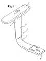
- Fig. 1 the arm support with the stand for a chair in an oblique view;
- Fig. 2 in a front view;
- Fig. 3 in a lateral view:
- Fig. 4 a view from below of the arm support withoutthe stand;
- Fig. 5 a longitudinal section of the arm supportfollowing line V-V of Fig. 4;
- Fig. 6 a top view of the support plate of the stand,directly connected to the arm support;
- Fig. 7 a vertical section of the stand and
- Fig. 8 a cross section of the stand following lineVIII-VIII of Fig. 7 and
- Fig. 9 a schematic longitudinal section ofindentations placed in a row, whose longitudinal sidesare located one beside the other, said indentations beingshaped like ribs and working as stopping elements.
- The arm support 1 for a chair, the latter not beingshown, leans onto an
upright stand 2. Saidstand 2 has atelescopic conformation and shows a fixed bar-shaped drawpiece 3 with a lower fastening flange 4, by means ofwhich the arm support or itsstand 2 can be fastened toa chair frame. Moreover, said stand 2 shows a cone-shapedtubular element 5, the cone-shaped stroke of saidtubularelement 5 widening upwards. - An
operating button 6 is provided in saidtubular element 5 under thearm support 1, its function being explainedwith more details later on. - Fig. 4 shows a view from below of the
arm support 1without thestand 2. A rectangular notch is obtained inthe lower side of saidarm support 1, said notch showinga substantiallyflat bottom 8 to which afirst guideplate 9 is fastened, in this case by means of bothscrews 10. The length and width of thisfirst guide plate 9 aresubstantially the same as those referring to thenotch 7,so that thisfirst guide plate 9 can be containedcompletely inside saidnotch 7.Longitudinal guide openings 12 are provided near thelongitudinal sides 11of thisfirst guide plate 9, saidguide openings 12covering only approximately half the length of the firstguide plate and being also shifted longitudinally onewith respect to the other, as shown in fig. 4. Stoppingelements are arranged in a row on the longitudinal sideof saidguide openings 12 and are connected to thelatter, said stopping elements consisting of rib-shapedindentations 13 with their longitudinal sides one besidethe other. The height of said rib-shaped indentations 13is smaller than the thickness of the guide plate on whichthey lie, as schematically shown in the longitudinalsection of Fig. 9. In the example of embodiment shownsaid rib-shaped indentations 13 of the first guide plateproject upwards, that is to say, out of the drawing planeof Fig. 4. - On said first guide plate a
second guide plate 14 issupported in a movable position by means ofsliders 15,saidsliders 15 coupling geometrically the rear side oftheguide openings 12. Saidsliders 15 are fastened bymeans ofpins 16, which themselves are fixed to saidsecond guide plate 14. Screws and nuts can be used asguide pins 16 andsliders 15. Acentral hole 17, locatedon saidsecond guide plate 14, houses a kingpin 18, whichis connected to thestand 2. As for theindentations 13of thefirst guide plate 9, arranged in a row, thesecondguide plate 14 is provided with corresponding rowsections ofanalogous indentations 19, which are directedagainst theindentations 13 of the first guide plate. Inaddition to these straight rows ofindentations 19,otherindentations 20, arranged in a row having the shape ofthe arc of a circle, are placed around thecentral hole 17, said rib-shaped indentations 20, here arranged alongthe line of an arc, projecting upwards with respect tothe drawing plane (fig. 4), that is to say, projectingupwards with respect to the surface of thesecond guide plate 14 which is visible here. Springs clamping bothguide plates central hole 17 in thesecond guide plate 14and reaching a slot-shaped recess running parallel to theguide openings 12 of thefirst guide plate 9, saidslot-shaped recess being indicated in fig. 4 by means ofadashed line 21. The axial length of said slot-shapedrecess, indicated by thedashed line 21, corresponds tothe horizontal shift of thearm support 1. Fig. 4 showsthat bothguide plates arrow 22, each position alongthis shift being maintained by means of saidindentations - The upper part of the
tubular element 5 of thestand 2 isclosed by means of asupport plate 23, shown in frontview (following arrow 24 in fig. 7) in fig. 6. Saidsupport plate 23 is provided with rib-shaped indentations 26, arranged on arc lines around thecentral hole 25,saidindentations 26 projecting upwards with respect totheupper side 27 of saidsupport plate 23. Theirposition and arrangement are analogous to those of theindentations 20 on thesecond guide plate 14. - The
draw piece 3, having a single-axis symmetrical crosssection 34 (fig. 8), shows twotoothed rims 28, which arearranged on opposite sides of saiddraw piece 3. Saidtoothed rims constitute the bottom side of groovesrunning vertically, said grooves or the toothed rimscontained herein are symmetrical to thesymmetry axis 29of thecross section 34 of thedraw piece 3. Thetubularelement 5 is provided with a two-arm regulation lever 31,running vertically around anaxis 30, fixed with respectto saidtubular element 5, the lower end of saidregulation lever 31 being coupled geometrically to one ofthetoothed rims 28 and theaforesaid operating button 6being fixed on its upper arm. The upper end of saidregulation lever 31 is supported by means of aspring 32,which maintains saidregulation lever 31 in the positionshown in fig. 7. - The details referring to the connection between the
tubular element 5 and thesupport plate 23 or between thestand 2 and thearm support 1 are not illustrated here. - The present document shows that the
arm support 1 can beshifted with respect to thesecond guide plate 14 inlongitudinal direction (arrow 22), the single positionsof said shift being maintained by means of theindentations - Moreover, the
arm support 1 can be turned around thekingpin 18 on a horizontal plane, here again the singlepositions of said shift being maintained by means of theindentations depth 33 of thenotch 7 can be sized in such a way that at least thesupport plate 23 of thetubular element 5 can be placedwithin saidnotch 7, so that during the rotation saidsupport plate 23 abuts with its rims onto the sides ofsaidnotch 7. However, it is also possible to provide,between thesupport plate 23 and thesecond guide plate 14, bounding elements, for instance a pin arranged in anarc-shaped recess, the length of the arc of saidarc-shaped recess defining the amplitude of the rotationangle. - In order to regulate the height of the
arm support 1 theoperating button 6 should be pressed so as to raise thetubular element 5 as far as the desired height isreached. Theoperating button 6 is then released and thespring 32 turns the regulation lever 31 back to its restposition. Thanks to the shape of the cross section of thedraw piece 3 and to the arrangement of thetoothed rims 28, the arm support described here can be used both forthe right-hand and for the left-hand side of a chair. Thetubular element 5 should only be taken out of thedraw piece 3, then rotated of 180 degrees and eventuallyslipped back onto thedraw piece 3. Not only does thismake storage easier, but it also reduces productioncosts, since the same arm support can be used for theright-hand and left-hand side of an armchair.
Claims (10)
- Arm support for a chair provided with an uprightstand (2), which is fixed to the chair and on whose upperend the arm support (1) is supported in a movableposition on a substantially horizontal plane and it maypossibly turn around a vertical axis, characterized inthat said arm support comprises a first guide plate (9)placed on the lower side of the arm support (1), providedwith guide openings (12) arranged on the rims and runningalong the longitudinal direction of the arm support, inwhich sliders (15) coupling geometrically the guideopenings (12) are present, said sliders (15) beingtightly connected to a second guide plate (14), thelength of the second guide plate (14) along the shiftdirection being smaller than the length of the firstguide plate and the second guide plate (14) beingconnected to the stand (2).
- Arm support as claimed in claim 1, wherein couplingelements are provided between the first and the secondguide plate (9, 14), and said coupling elements consistsof rib-shaped indentations (13), which are arranged inrows and whose longitudinal sides are located one besidethe other
- Arm support as claimed in claim 2, wherein the heightof the rib-shaped indentations is smaller than thethickness of the guide plates where they are located(fig. 9).
- Arm support as claimed in claim 1, wherein the guideopenings (12) provided in the first guide plate (9) coveronly approximately half the length of said guide plate(9) and both guide openings (12) can be shifted one withrespect to the other in the longitudinal direction of theguide plate (9).
- Arm support as claime din claim 4, wherein a straightrow of stopping elements is provided after to the guideopening (12) of the first guide plate.
- Arm support as claimed in claim 1, wherein thesliders (15) of the second guide plate (14) are providedon two corners of said plate, one diagonal to the other,and a straight row of indentations (19) shaped asstopping elements runs parallel to the longitudinal rimsof this second guide plate (14).
- Arm support as claimed in claim 6, wherein the secondguide plate (14) shows a central hole (17) housing akingpin (18), which is connected in its turn with thestand (2), and at least one row of indentations (20)shaped as stopping elements and running around said axisas an arc, is provided around the central hole (17)working as the center.
- Arm support as claimed in claim 7, wherein the stand(2) shows an upper support plate (23) provided with thekingpin (18), and at least one row of indentations (26)shaped as stopping elements and running around said axisas an arc, is provided around the axis of the kingpin(18), working as the center, said indentationscooperating and being geometrically coupled with theindentations (20) of the second guide plate (14), shapedas stopping elements and being arranged as an arc.
- Arm support as claimed in claim 1, whose uprightstand (2) has a telescopic conformation and it isprovided with a fixed bar-shaped draw piece (3), showingat least a longitudinal toothed rim (28), and with atubular element (5) housing said draw piece (3), and thetubular element (5) is provided with at least a two-armspring-loaded regulation lever (31), running inlongitudinal direction and connectable to the toothed rim(28), the upper end of said lever projecting through anopening in the tubular element (5), thus forming anoperating button (6), wherein the draw piece (3) shows asymmetrical cross section (34) with at least one axis,and the toothed rim (28) is provided in pairs on thediametrically opposite longitudinal sides of the draw piece (3), the toothed rim (28) forming the bottomportion of vertical longitudinal grooves.
- Arm support as claimed in claim 1, wherein the firstand the second guide plates (9, 14) are placed in a notch(7) located on the lower side of the arm support (1), thedepth (33) of said notch (7) being greater than the sumof the thickness of both guide plates (9, 14), and theupper support plate (23) closing the upper side of thetubular element (5) is placed within said notch (7).
Priority Applications (1)
| Application Number | Priority Date | Filing Date | Title |
|---|---|---|---|
| AT00106290TATE255346T1 (en) | 1999-04-12 | 2000-03-23 | ARMRESTS FOR A CHAIR |
Applications Claiming Priority (2)
| Application Number | Priority Date | Filing Date | Title |
|---|---|---|---|
| AT0063699AAT407003B (en) | 1999-04-12 | 1999-04-12 | ARM REST FOR A SEAT FURNITURE |
| AT63699 | 1999-04-12 |
Publications (2)
| Publication Number | Publication Date |
|---|---|
| EP1044634A1true EP1044634A1 (en) | 2000-10-18 |
| EP1044634B1 EP1044634B1 (en) | 2003-12-03 |
Family
ID=3495844
Family Applications (1)
| Application Number | Title | Priority Date | Filing Date |
|---|---|---|---|
| EP00106290AExpired - LifetimeEP1044634B1 (en) | 1999-04-12 | 2000-03-23 | Arm support for a chair |
Country Status (6)
| Country | Link |
|---|---|
| US (1) | US6502904B1 (en) |
| EP (1) | EP1044634B1 (en) |
| AT (2) | AT407003B (en) |
| BR (1) | BR0001580A (en) |
| CA (1) | CA2302902A1 (en) |
| DE (1) | DE60006885D1 (en) |
Cited By (8)
| Publication number | Priority date | Publication date | Assignee | Title |
|---|---|---|---|---|
| NL1018820C2 (en)* | 2001-08-24 | 2003-02-25 | Bma Ergonomics B V | Movable armrest and equipped chair. |
| US6637072B2 (en) | 2000-09-29 | 2003-10-28 | Formway Furniture Limited | Castored base for an office chair |
| EP1216632A3 (en)* | 2000-12-18 | 2003-11-05 | Kinnarps Ab | Adjustable armrest |
| US6802566B2 (en) | 2000-09-28 | 2004-10-12 | Formway Furniture Limited | Arm assembly for a chair |
| US6840582B2 (en) | 2002-05-14 | 2005-01-11 | Formway Furniture Limited | Height adjustable arm assembly |
| EP1457140A3 (en)* | 2003-03-13 | 2005-02-09 | Froli Kunststoffwerk Heinrich Fromme OHG | Arm support, particularly for office chairs and swivel chairs |
| EP2502521A1 (en)* | 2011-03-21 | 2012-09-26 | Isotech Products Incorporated | Armrest adjustment member |
| USD1063474S1 (en) | 2022-09-07 | 2025-02-25 | Steelcase Inc. | Chair |
Families Citing this family (71)
| Publication number | Priority date | Publication date | Assignee | Title |
|---|---|---|---|---|
| IT1315480B1 (en)* | 2000-07-24 | 2003-02-18 | Plasticline Srl | ADJUSTABLE ARMREST FOR CHAIRS |
| DE10125996A1 (en)* | 2001-05-18 | 2002-11-21 | Bock 1 Gmbh & Co | Arm rest for office chair comprises telescopic column on which arm rest itself is mounted, mounting having no release mechanism and allowing rest to be adjusted longitudinally and rotated |
| ES2252372T3 (en)* | 2002-10-04 | 2006-05-16 | Sedus Stoll Ag | REPOSABRAZOS. |
| AU2003277261A1 (en)* | 2002-10-18 | 2004-05-13 | Center For Design Research And Development N.V. | Stackable chair |
| CA2411986C (en)* | 2002-11-18 | 2010-03-09 | Conrad M. Marini | Armrest support |
| US6908158B2 (en) | 2003-01-02 | 2005-06-21 | Haworth, Inc. | Lateral motion chair arm mechanism for chair arm |
| CA2425374C (en)* | 2003-04-14 | 2008-09-23 | Allseating Corporation | Adjustable four plate assembly for a chair |
| US6659561B1 (en)* | 2003-04-26 | 2003-12-09 | Hwang Pao Lee | Arm rest adjustable forwardly and rearwardly |
| US6923505B2 (en)* | 2003-07-01 | 2005-08-02 | The Regents Of The University Of California | Ergonomically neutral arm support system |
| USD509969S1 (en) | 2003-09-05 | 2005-09-27 | Steelcase Development Corporation | Seating unit |
| US6883872B1 (en)* | 2003-12-30 | 2005-04-26 | Wen-Fa Su | Adjustable armrest with an auxiliary security unit |
| US6948775B2 (en)* | 2004-02-20 | 2005-09-27 | Po-Chuan Tsai | Office chair armrest |
| US20050189807A1 (en)* | 2004-02-27 | 2005-09-01 | Norman Christopher J. | Chair with functional armrest |
| USD536890S1 (en) | 2004-03-03 | 2007-02-20 | Steelcase Development Corporation | Seating unit |
| USD544722S1 (en) | 2004-06-07 | 2007-06-19 | Steelcase Development Corporation | Chair |
| USD552368S1 (en) | 2004-06-07 | 2007-10-09 | Steelcase Development Corporation | Chair |
| USD554384S1 (en) | 2004-06-07 | 2007-11-06 | Steelcase Development Corporation | Chair |
| WO2006094260A2 (en)* | 2005-03-01 | 2006-09-08 | Haworth, Inc. | Arm assembly for a chair |
| US8235468B2 (en) | 2005-03-01 | 2012-08-07 | Haworth, Inc. | Arm assembly for a chair |
| US7341313B2 (en)* | 2005-04-08 | 2008-03-11 | Steelcase Development Corporation | Adjustable armrest with motion control |
| DE202005005988U1 (en)* | 2005-04-13 | 2005-07-14 | Bock 1 Gmbh & Co. Kg | Armrest, for office chairs, is mounted on support column using multifunctional mounting which incorporates transverse and longitudinal adjusting systems and pivot |
| US7201449B2 (en)* | 2005-05-04 | 2007-04-10 | Fusco Industrial Corporation | Multiple direction adjustment armrest |
| US7188907B1 (en)* | 2005-05-24 | 2007-03-13 | Yu-Shan Lai | Armrest assembly having a position adjusting function |
| TWI280107B (en)* | 2006-01-19 | 2007-05-01 | Yi Chun Entpr Ltd | Mechanism for relatively engaging and locking two member of chair arm |
| TWM298385U (en)* | 2006-04-27 | 2006-10-01 | Huang-Bau Li | Armrest adjusting structure |
| US7559609B2 (en)* | 2006-08-15 | 2009-07-14 | Po-Chuan Tsai | Multifunctional armrest assembly for chair |
| WO2008140938A1 (en)* | 2007-05-10 | 2008-11-20 | Porter Group, Llc | Vehicle seat armrest assembly |
| US7806470B2 (en)* | 2008-11-20 | 2010-10-05 | Deere & Company | Vehicle command armrest assembly |
| US8226171B2 (en)* | 2010-11-17 | 2012-07-24 | Tien Ching Fang | Armrest |
| DE202011001282U1 (en)* | 2011-01-10 | 2012-04-18 | Bock 1 Gmbh & Co. Kg | Armrest, especially for an office chair |
| TWM419485U (en)* | 2011-05-06 | 2012-01-01 | Chuan Hsing Chemical Industry Co Ltd | Armrest of seat |
| USD699061S1 (en) | 2012-09-20 | 2014-02-11 | Steelcase Inc. | Arm assembly |
| USD694539S1 (en) | 2012-09-20 | 2013-12-03 | Steelcase Inc. | Chair |
| USD694540S1 (en) | 2012-09-20 | 2013-12-03 | Steelcase Inc. | Chair |
| USD781605S1 (en) | 2015-04-24 | 2017-03-21 | Steelcase Inc. | Chair |
| USD697727S1 (en) | 2012-09-20 | 2014-01-21 | Steeelcase Inc. | Chair |
| USD683151S1 (en) | 2012-09-20 | 2013-05-28 | Steelcase Inc. | Chair |
| USD683150S1 (en) | 2012-09-20 | 2013-05-28 | Steelcase Inc. | Chair |
| USD942767S1 (en) | 2012-09-20 | 2022-02-08 | Steelcase Inc. | Chair assembly |
| USD694537S1 (en) | 2012-09-20 | 2013-12-03 | Steelcase Inc. | Chair |
| USD698165S1 (en) | 2012-09-20 | 2014-01-28 | Steelcase Inc. | Chair |
| US11304528B2 (en) | 2012-09-20 | 2022-04-19 | Steelcase Inc. | Chair assembly with upholstery covering |
| USD698166S1 (en) | 2012-09-20 | 2014-01-28 | Steelcase Inc. | Chair |
| USD694538S1 (en) | 2012-09-20 | 2013-12-03 | Steelcase Inc. | Chair |
| USD697729S1 (en) | 2012-09-20 | 2014-01-21 | Steelcase Inc. | Chair |
| US8998339B2 (en) | 2012-09-20 | 2015-04-07 | Steelcase Inc. | Chair assembly with upholstery covering |
| USD699958S1 (en) | 2012-09-20 | 2014-02-25 | Steelcase Inc. | Chair |
| USD697726S1 (en) | 2012-09-20 | 2014-01-21 | Steelcase Inc. | Chair |
| US11229294B2 (en) | 2012-09-20 | 2022-01-25 | Steelcase Inc. | Chair assembly with upholstery covering |
| USD699957S1 (en) | 2012-09-20 | 2014-02-25 | Steelcase Inc. | Chair |
| USD699959S1 (en) | 2012-09-20 | 2014-02-25 | Steelcase Inc. | Chair |
| USD694536S1 (en) | 2012-09-20 | 2013-12-03 | Steelcase Inc. | Chair |
| USD697730S1 (en) | 2012-09-20 | 2014-01-21 | Steelcase Inc. | Chair |
| USD688907S1 (en) | 2012-09-20 | 2013-09-03 | Steelcase Inc. | Arm assembly |
| USD701053S1 (en) | 2012-09-20 | 2014-03-18 | Steelcase Inc. | Chair |
| USD707976S1 (en) | 2013-06-07 | 2014-07-01 | Steelcase Inc. | Chair |
| USD721529S1 (en) | 2013-06-07 | 2015-01-27 | Steelcase Inc. | Handle apparatus |
| USD703987S1 (en) | 2013-06-07 | 2014-05-06 | Steelcase Inc. | Chair |
| USD706547S1 (en) | 2013-06-07 | 2014-06-10 | Steelcase Inc. | Chair |
| US9044098B2 (en) | 2012-11-16 | 2015-06-02 | Holland Plastics Corporation | Adjustable armrest assembly |
| US9320360B2 (en) | 2012-12-14 | 2016-04-26 | Holland Plastics Corporation | Armrest assembly |
| USD704487S1 (en) | 2013-06-07 | 2014-05-13 | Steelcase Inc. | Chair |
| USD703988S1 (en) | 2013-06-07 | 2014-05-06 | Steelcase Inc. | Chair |
| US20160101867A1 (en)* | 2014-10-13 | 2016-04-14 | Gulfstream Aerospace Corporation | Aircrew seat |
| USD781604S1 (en) | 2015-04-24 | 2017-03-21 | Steelcase Inc. | Chair |
| USD760526S1 (en) | 2015-04-24 | 2016-07-05 | Steelcase Inc. | Headrest assembly |
| USD758774S1 (en) | 2015-04-24 | 2016-06-14 | Steelcase Inc. | Headrest assembly |
| USD759415S1 (en) | 2015-04-24 | 2016-06-21 | Steelcase Inc. | Headrest |
| USD888479S1 (en)* | 2018-06-04 | 2020-06-30 | Steelcase Inc. | Chair arm |
| USD889152S1 (en)* | 2018-06-05 | 2020-07-07 | Herman Miller, Inc. | Chair |
| USD1055606S1 (en)* | 2022-02-17 | 2024-12-31 | Viccarbe Habitat, S.L. | Armrest |
Citations (12)
| Publication number | Priority date | Publication date | Assignee | Title |
|---|---|---|---|---|
| DE8716965U1 (en) | 1987-12-24 | 1988-02-11 | Ignaz Vogel Gmbh Und Co Kg - Fahrzeugsitze, 7500 Karlsruhe | Armchair |
| DE8814053U1 (en) | 1987-11-23 | 1989-01-12 | Grahl GmbH Sitzmöbelfabrik, 3074 Steyerberg | Chair, especially swivel chair |
| US4961610A (en)* | 1989-08-21 | 1990-10-09 | Midmark Corporation | Clam shell armrest |
| DE4317610A1 (en) | 1993-05-27 | 1994-12-01 | Trendoffice Bueromoebel | Height-adjustable arm for a chair |
| US5382079A (en)* | 1993-10-25 | 1995-01-17 | Chromcraft Revington, Inc. | Adjustable arm attachable to a chair body |
| US5407249A (en) | 1990-10-15 | 1995-04-18 | Bonutti; Peter M. | Armrest assembly |
| DE29511267U1 (en) | 1995-07-12 | 1995-09-21 | Martens, Irene, 47627 Kevelaer | Armrest |
| DE4415264A1 (en) | 1994-04-15 | 1995-10-26 | Taipei Design Center Duesseldo | Swivel office chair |
| DE29502429U1 (en) | 1995-02-15 | 1995-11-02 | Froli Kunststoffe Heinrich Fromme, 33758 Schloß Holte-Stukenbrock | Armrest for a seat element |
| US5586811A (en)* | 1994-08-15 | 1996-12-24 | Tornero; Lino E. | Adjustment device for chair arms |
| DE29519794U1 (en) | 1995-12-13 | 1997-04-10 | Ropp, Horst von der, Dipl.-Ing., 50735 Köln | Armrest |
| US5876097A (en)* | 1998-07-20 | 1999-03-02 | Cao; Zi-Wen | Adjustable armrest device |
Family Cites Families (6)
| Publication number | Priority date | Publication date | Assignee | Title |
|---|---|---|---|---|
| US5369805A (en)* | 1991-09-05 | 1994-12-06 | Bergsten; Jeffrey D. | Ergonomic arm support |
| US5324096A (en)* | 1992-03-02 | 1994-06-28 | Hon Industries Inc. | Adjustable height chair arm |
| US5655814A (en)* | 1996-03-07 | 1997-08-12 | Shin Yeh Enterprise Co., Ltd. | Adjustable chair-armrest assembly |
| US6076892A (en)* | 1997-06-04 | 2000-06-20 | Knoll, Inc. | Multi-adjustable armrest assembly |
| US5927811A (en)* | 1998-02-27 | 1999-07-27 | Shin Yen Enterprise Co., Ltd. | Adjustable chair-armrest assembly |
| US6062647A (en)* | 1999-07-08 | 2000-05-16 | Mei; Teng-Fu | Adjustable armrest assembly |
- 1999
- 1999-04-12ATAT0063699Apatent/AT407003B/ennot_activeIP Right Cessation
- 2000
- 2000-03-23ATAT00106290Tpatent/ATE255346T1/ennot_activeIP Right Cessation
- 2000-03-23DEDE60006885Tpatent/DE60006885D1/ennot_activeExpired - Lifetime
- 2000-03-23EPEP00106290Apatent/EP1044634B1/ennot_activeExpired - Lifetime
- 2000-03-27USUS09/536,496patent/US6502904B1/ennot_activeExpired - Fee Related
- 2000-03-29CACA002302902Apatent/CA2302902A1/ennot_activeAbandoned
- 2000-04-11BRBR0001580-6Apatent/BR0001580A/ennot_activeApplication Discontinuation
Patent Citations (12)
| Publication number | Priority date | Publication date | Assignee | Title |
|---|---|---|---|---|
| DE8814053U1 (en) | 1987-11-23 | 1989-01-12 | Grahl GmbH Sitzmöbelfabrik, 3074 Steyerberg | Chair, especially swivel chair |
| DE8716965U1 (en) | 1987-12-24 | 1988-02-11 | Ignaz Vogel Gmbh Und Co Kg - Fahrzeugsitze, 7500 Karlsruhe | Armchair |
| US4961610A (en)* | 1989-08-21 | 1990-10-09 | Midmark Corporation | Clam shell armrest |
| US5407249A (en) | 1990-10-15 | 1995-04-18 | Bonutti; Peter M. | Armrest assembly |
| DE4317610A1 (en) | 1993-05-27 | 1994-12-01 | Trendoffice Bueromoebel | Height-adjustable arm for a chair |
| US5382079A (en)* | 1993-10-25 | 1995-01-17 | Chromcraft Revington, Inc. | Adjustable arm attachable to a chair body |
| DE4415264A1 (en) | 1994-04-15 | 1995-10-26 | Taipei Design Center Duesseldo | Swivel office chair |
| US5586811A (en)* | 1994-08-15 | 1996-12-24 | Tornero; Lino E. | Adjustment device for chair arms |
| DE29502429U1 (en) | 1995-02-15 | 1995-11-02 | Froli Kunststoffe Heinrich Fromme, 33758 Schloß Holte-Stukenbrock | Armrest for a seat element |
| DE29511267U1 (en) | 1995-07-12 | 1995-09-21 | Martens, Irene, 47627 Kevelaer | Armrest |
| DE29519794U1 (en) | 1995-12-13 | 1997-04-10 | Ropp, Horst von der, Dipl.-Ing., 50735 Köln | Armrest |
| US5876097A (en)* | 1998-07-20 | 1999-03-02 | Cao; Zi-Wen | Adjustable armrest device |
Cited By (15)
| Publication number | Priority date | Publication date | Assignee | Title |
|---|---|---|---|---|
| US6874852B2 (en) | 2000-09-28 | 2005-04-05 | Formway Furniture Limited | Lumbar support |
| US7798573B2 (en) | 2000-09-28 | 2010-09-21 | Formway Furniture Limited | Reclinable chair |
| US7441839B2 (en) | 2000-09-28 | 2008-10-28 | Formway Furniture Limited | Reclinable chair |
| US6802566B2 (en) | 2000-09-28 | 2004-10-12 | Formway Furniture Limited | Arm assembly for a chair |
| US6817667B2 (en) | 2000-09-28 | 2004-11-16 | Formway Furniture Limited | Reclinable chair |
| US6910741B2 (en) | 2000-09-28 | 2005-06-28 | Formway Furniture Limited | Lumbar support |
| US6908159B2 (en) | 2000-09-28 | 2005-06-21 | Formway Furniture Limited | Seat for a reclining office chair |
| US6637072B2 (en) | 2000-09-29 | 2003-10-28 | Formway Furniture Limited | Castored base for an office chair |
| EP1216632A3 (en)* | 2000-12-18 | 2003-11-05 | Kinnarps Ab | Adjustable armrest |
| NL1018820C2 (en)* | 2001-08-24 | 2003-02-25 | Bma Ergonomics B V | Movable armrest and equipped chair. |
| EP1287765A1 (en)* | 2001-08-24 | 2003-03-05 | BMA Ergonomics B.V. | Movable armrest and seat equipped therewith |
| US6840582B2 (en) | 2002-05-14 | 2005-01-11 | Formway Furniture Limited | Height adjustable arm assembly |
| EP1457140A3 (en)* | 2003-03-13 | 2005-02-09 | Froli Kunststoffwerk Heinrich Fromme OHG | Arm support, particularly for office chairs and swivel chairs |
| EP2502521A1 (en)* | 2011-03-21 | 2012-09-26 | Isotech Products Incorporated | Armrest adjustment member |
| USD1063474S1 (en) | 2022-09-07 | 2025-02-25 | Steelcase Inc. | Chair |
Also Published As
| Publication number | Publication date |
|---|---|
| ATE255346T1 (en) | 2003-12-15 |
| AT407003B (en) | 2000-11-27 |
| DE60006885D1 (en) | 2004-01-15 |
| BR0001580A (en) | 2000-10-31 |
| US6502904B1 (en) | 2003-01-07 |
| ATA63699A (en) | 2000-04-15 |
| EP1044634B1 (en) | 2003-12-03 |
| CA2302902A1 (en) | 2000-10-12 |
Similar Documents
| Publication | Publication Date | Title |
|---|---|---|
| EP1044634B1 (en) | Arm support for a chair | |
| US20070226928A1 (en) | Dishwasher | |
| US20070152114A1 (en) | Stand for display device | |
| US4884499A (en) | Portable grill | |
| US20110073738A1 (en) | Display Device | |
| JP2023169428A (en) | slope device | |
| EP0107601B1 (en) | Adjustable support for a television and video recorder with a cassette holder shelf | |
| US4732295A (en) | Receptacle with swinging cover | |
| JP3406630B2 (en) | Table mounting device that can also be used as an armrest | |
| JP4471440B2 (en) | Folding table | |
| JPH048454Y2 (en) | ||
| US5527009A (en) | Wall-mounted bucket pourer | |
| JP3790836B2 (en) | Support device | |
| JP4280861B2 (en) | End plate mounting device | |
| CN221383381U (en) | Bathtub cover support | |
| JPH10215953A (en) | Folding table | |
| JP3675145B2 (en) | Chair armrest device | |
| JP3675144B2 (en) | Chair armrest device | |
| RU174249U1 (en) | CHAIR SUPPORT FOR CHAIR | |
| JPH0711658Y2 (en) | Seat plate rotation device | |
| JPH0418172Y2 (en) | ||
| JPH0899576A (en) | Box type cup holder | |
| JPH07102Y2 (en) | Tilting shelf | |
| CN114992448B (en) | Television base | |
| JPH0622024Y2 (en) | Gutter receiving device |
Legal Events
| Date | Code | Title | Description |
|---|---|---|---|
| PUAI | Public reference made under article 153(3) epc to a published international application that has entered the european phase | Free format text:ORIGINAL CODE: 0009012 | |
| AK | Designated contracting states | Kind code of ref document:A1 Designated state(s):AT BE CH CY DE DK ES FI FR GB GR IE IT LI LU MC NL PT SE | |
| AX | Request for extension of the european patent | Free format text:AL;LT;LV;MK;RO;SI | |
| 17P | Request for examination filed | Effective date:20010129 | |
| AKX | Designation fees paid | Free format text:AT BE CH CY DE DK ES FI FR GB GR IE IT LI LU MC NL PT SE | |
| GRAH | Despatch of communication of intention to grant a patent | Free format text:ORIGINAL CODE: EPIDOS IGRA | |
| GRAS | Grant fee paid | Free format text:ORIGINAL CODE: EPIDOSNIGR3 | |
| GRAA | (expected) grant | Free format text:ORIGINAL CODE: 0009210 | |
| AK | Designated contracting states | Kind code of ref document:B1 Designated state(s):AT BE CH CY DE DK ES FI FR GB GR IE IT LI LU MC NL PT SE | |
| PG25 | Lapsed in a contracting state [announced via postgrant information from national office to epo] | Ref country code:IT Free format text:LAPSE BECAUSE OF FAILURE TO SUBMIT A TRANSLATION OF THE DESCRIPTION OR TO PAY THE FEE WITHIN THE PRESCRIBED TIME-LIMIT;WARNING: LAPSES OF ITALIAN PATENTS WITH EFFECTIVE DATE BEFORE 2007 MAY HAVE OCCURRED AT ANY TIME BEFORE 2007. THE CORRECT EFFECTIVE DATE MAY BE DIFFERENT FROM THE ONE RECORDED. Effective date:20031203 Ref country code:LI Free format text:LAPSE BECAUSE OF FAILURE TO SUBMIT A TRANSLATION OF THE DESCRIPTION OR TO PAY THE FEE WITHIN THE PRESCRIBED TIME-LIMIT Effective date:20031203 Ref country code:BE Free format text:LAPSE BECAUSE OF FAILURE TO SUBMIT A TRANSLATION OF THE DESCRIPTION OR TO PAY THE FEE WITHIN THE PRESCRIBED TIME-LIMIT Effective date:20031203 Ref country code:AT Free format text:LAPSE BECAUSE OF FAILURE TO SUBMIT A TRANSLATION OF THE DESCRIPTION OR TO PAY THE FEE WITHIN THE PRESCRIBED TIME-LIMIT Effective date:20031203 Ref country code:CY Free format text:LAPSE BECAUSE OF FAILURE TO SUBMIT A TRANSLATION OF THE DESCRIPTION OR TO PAY THE FEE WITHIN THE PRESCRIBED TIME-LIMIT Effective date:20031203 Ref country code:CH Free format text:LAPSE BECAUSE OF FAILURE TO SUBMIT A TRANSLATION OF THE DESCRIPTION OR TO PAY THE FEE WITHIN THE PRESCRIBED TIME-LIMIT Effective date:20031203 Ref country code:NL Free format text:LAPSE BECAUSE OF FAILURE TO SUBMIT A TRANSLATION OF THE DESCRIPTION OR TO PAY THE FEE WITHIN THE PRESCRIBED TIME-LIMIT Effective date:20031203 Ref country code:FR Free format text:LAPSE BECAUSE OF FAILURE TO SUBMIT A TRANSLATION OF THE DESCRIPTION OR TO PAY THE FEE WITHIN THE PRESCRIBED TIME-LIMIT Effective date:20031203 Ref country code:FI Free format text:LAPSE BECAUSE OF FAILURE TO SUBMIT A TRANSLATION OF THE DESCRIPTION OR TO PAY THE FEE WITHIN THE PRESCRIBED TIME-LIMIT Effective date:20031203 | |
| REG | Reference to a national code | Ref country code:GB Ref legal event code:FG4D | |
| REG | Reference to a national code | Ref country code:CH Ref legal event code:EP | |
| REG | Reference to a national code | Ref country code:IE Ref legal event code:FG4D | |
| REF | Corresponds to: | Ref document number:60006885 Country of ref document:DE Date of ref document:20040115 Kind code of ref document:P | |
| PG25 | Lapsed in a contracting state [announced via postgrant information from national office to epo] | Ref country code:GR Free format text:LAPSE BECAUSE OF FAILURE TO SUBMIT A TRANSLATION OF THE DESCRIPTION OR TO PAY THE FEE WITHIN THE PRESCRIBED TIME-LIMIT Effective date:20040303 Ref country code:SE Free format text:LAPSE BECAUSE OF FAILURE TO SUBMIT A TRANSLATION OF THE DESCRIPTION OR TO PAY THE FEE WITHIN THE PRESCRIBED TIME-LIMIT Effective date:20040303 Ref country code:DK Free format text:LAPSE BECAUSE OF FAILURE TO SUBMIT A TRANSLATION OF THE DESCRIPTION OR TO PAY THE FEE WITHIN THE PRESCRIBED TIME-LIMIT Effective date:20040303 | |
| PG25 | Lapsed in a contracting state [announced via postgrant information from national office to epo] | Ref country code:DE Free format text:LAPSE BECAUSE OF FAILURE TO SUBMIT A TRANSLATION OF THE DESCRIPTION OR TO PAY THE FEE WITHIN THE PRESCRIBED TIME-LIMIT Effective date:20040304 | |
| PG25 | Lapsed in a contracting state [announced via postgrant information from national office to epo] | Ref country code:ES Free format text:LAPSE BECAUSE OF FAILURE TO SUBMIT A TRANSLATION OF THE DESCRIPTION OR TO PAY THE FEE WITHIN THE PRESCRIBED TIME-LIMIT Effective date:20040314 | |
| PG25 | Lapsed in a contracting state [announced via postgrant information from national office to epo] | Ref country code:LU Free format text:LAPSE BECAUSE OF NON-PAYMENT OF DUE FEES Effective date:20040323 Ref country code:IE Free format text:LAPSE BECAUSE OF NON-PAYMENT OF DUE FEES Effective date:20040323 Ref country code:GB Free format text:LAPSE BECAUSE OF NON-PAYMENT OF DUE FEES Effective date:20040323 | |
| PG25 | Lapsed in a contracting state [announced via postgrant information from national office to epo] | Ref country code:MC Free format text:LAPSE BECAUSE OF NON-PAYMENT OF DUE FEES Effective date:20040331 | |
| NLV1 | Nl: lapsed or annulled due to failure to fulfill the requirements of art. 29p and 29m of the patents act | ||
| REG | Reference to a national code | Ref country code:CH Ref legal event code:PL | |
| PLBE | No opposition filed within time limit | Free format text:ORIGINAL CODE: 0009261 | |
| STAA | Information on the status of an ep patent application or granted ep patent | Free format text:STATUS: NO OPPOSITION FILED WITHIN TIME LIMIT | |
| GBPC | Gb: european patent ceased through non-payment of renewal fee | Effective date:20040323 | |
| 26N | No opposition filed | Effective date:20040906 | |
| EN | Fr: translation not filed | ||
| REG | Reference to a national code | Ref country code:IE Ref legal event code:MM4A | |
| PG25 | Lapsed in a contracting state [announced via postgrant information from national office to epo] | Ref country code:PT Free format text:LAPSE BECAUSE OF NON-PAYMENT OF DUE FEES Effective date:20040503 |