EP1042729B1 - System and methods for analyzing tooth shades - Google Patents
System and methods for analyzing tooth shadesDownload PDFInfo
- Publication number
- EP1042729B1 EP1042729B1EP99950091AEP99950091AEP1042729B1EP 1042729 B1EP1042729 B1EP 1042729B1EP 99950091 AEP99950091 AEP 99950091AEP 99950091 AEP99950091 AEP 99950091AEP 1042729 B1EP1042729 B1EP 1042729B1
- Authority
- EP
- European Patent Office
- Prior art keywords
- tooth
- image
- pixels
- pseudo
- shade
- Prior art date
- Legal status (The legal status is an assumption and is not a legal conclusion. Google has not performed a legal analysis and makes no representation as to the accuracy of the status listed.)
- Expired - Lifetime
Links
Images


Classifications
- G—PHYSICS
- G01—MEASURING; TESTING
- G01J—MEASUREMENT OF INTENSITY, VELOCITY, SPECTRAL CONTENT, POLARISATION, PHASE OR PULSE CHARACTERISTICS OF INFRARED, VISIBLE OR ULTRAVIOLET LIGHT; COLORIMETRY; RADIATION PYROMETRY
- G01J3/00—Spectrometry; Spectrophotometry; Monochromators; Measuring colours
- G01J3/46—Measurement of colour; Colour measuring devices, e.g. colorimeters
- A—HUMAN NECESSITIES
- A61—MEDICAL OR VETERINARY SCIENCE; HYGIENE
- A61C—DENTISTRY; APPARATUS OR METHODS FOR ORAL OR DENTAL HYGIENE
- A61C19/00—Dental auxiliary appliances
- A—HUMAN NECESSITIES
- A61—MEDICAL OR VETERINARY SCIENCE; HYGIENE
- A61C—DENTISTRY; APPARATUS OR METHODS FOR ORAL OR DENTAL HYGIENE
- A61C19/00—Dental auxiliary appliances
- A61C19/10—Supports for artificial teeth for transport or for comparison of the colour
- G—PHYSICS
- G01—MEASURING; TESTING
- G01J—MEASUREMENT OF INTENSITY, VELOCITY, SPECTRAL CONTENT, POLARISATION, PHASE OR PULSE CHARACTERISTICS OF INFRARED, VISIBLE OR ULTRAVIOLET LIGHT; COLORIMETRY; RADIATION PYROMETRY
- G01J3/00—Spectrometry; Spectrophotometry; Monochromators; Measuring colours
- G01J3/46—Measurement of colour; Colour measuring devices, e.g. colorimeters
- G01J3/462—Computing operations in or between colour spaces; Colour management systems
- G—PHYSICS
- G01—MEASURING; TESTING
- G01J—MEASUREMENT OF INTENSITY, VELOCITY, SPECTRAL CONTENT, POLARISATION, PHASE OR PULSE CHARACTERISTICS OF INFRARED, VISIBLE OR ULTRAVIOLET LIGHT; COLORIMETRY; RADIATION PYROMETRY
- G01J3/00—Spectrometry; Spectrophotometry; Monochromators; Measuring colours
- G01J3/46—Measurement of colour; Colour measuring devices, e.g. colorimeters
- G01J3/463—Colour matching
- G—PHYSICS
- G01—MEASURING; TESTING
- G01J—MEASUREMENT OF INTENSITY, VELOCITY, SPECTRAL CONTENT, POLARISATION, PHASE OR PULSE CHARACTERISTICS OF INFRARED, VISIBLE OR ULTRAVIOLET LIGHT; COLORIMETRY; RADIATION PYROMETRY
- G01J3/00—Spectrometry; Spectrophotometry; Monochromators; Measuring colours
- G01J3/46—Measurement of colour; Colour measuring devices, e.g. colorimeters
- G01J3/50—Measurement of colour; Colour measuring devices, e.g. colorimeters using electric radiation detectors
- G01J3/508—Measurement of colour; Colour measuring devices, e.g. colorimeters using electric radiation detectors measuring the colour of teeth
- G—PHYSICS
- G01—MEASURING; TESTING
- G01N—INVESTIGATING OR ANALYSING MATERIALS BY DETERMINING THEIR CHEMICAL OR PHYSICAL PROPERTIES
- G01N21/00—Investigating or analysing materials by the use of optical means, i.e. using sub-millimetre waves, infrared, visible or ultraviolet light
- G01N21/17—Systems in which incident light is modified in accordance with the properties of the material investigated
- G01N21/25—Colour; Spectral properties, i.e. comparison of effect of material on the light at two or more different wavelengths or wavelength bands
- G—PHYSICS
- G06—COMPUTING OR CALCULATING; COUNTING
- G06F—ELECTRIC DIGITAL DATA PROCESSING
- G06F18/00—Pattern recognition
- G06F18/20—Analysing
- G06F18/28—Determining representative reference patterns, e.g. by averaging or distorting; Generating dictionaries
- G—PHYSICS
- G06—COMPUTING OR CALCULATING; COUNTING
- G06T—IMAGE DATA PROCESSING OR GENERATION, IN GENERAL
- G06T7/00—Image analysis
- G06T7/90—Determination of colour characteristics
- G—PHYSICS
- G06—COMPUTING OR CALCULATING; COUNTING
- G06V—IMAGE OR VIDEO RECOGNITION OR UNDERSTANDING
- G06V10/00—Arrangements for image or video recognition or understanding
- G06V10/40—Extraction of image or video features
- G06V10/56—Extraction of image or video features relating to colour
- G—PHYSICS
- G06—COMPUTING OR CALCULATING; COUNTING
- G06V—IMAGE OR VIDEO RECOGNITION OR UNDERSTANDING
- G06V10/00—Arrangements for image or video recognition or understanding
- G06V10/70—Arrangements for image or video recognition or understanding using pattern recognition or machine learning
- G06V10/74—Image or video pattern matching; Proximity measures in feature spaces
- G06V10/75—Organisation of the matching processes, e.g. simultaneous or sequential comparisons of image or video features; Coarse-fine approaches, e.g. multi-scale approaches; using context analysis; Selection of dictionaries
- G06V10/751—Comparing pixel values or logical combinations thereof, or feature values having positional relevance, e.g. template matching
- G—PHYSICS
- G06—COMPUTING OR CALCULATING; COUNTING
- G06V—IMAGE OR VIDEO RECOGNITION OR UNDERSTANDING
- G06V10/00—Arrangements for image or video recognition or understanding
- G06V10/70—Arrangements for image or video recognition or understanding using pattern recognition or machine learning
- G06V10/77—Processing image or video features in feature spaces; using data integration or data reduction, e.g. principal component analysis [PCA] or independent component analysis [ICA] or self-organising maps [SOM]; Blind source separation
- G06V10/772—Determining representative reference patterns, e.g. averaging or distorting patterns; Generating dictionaries
Definitions
- the inventionis directed to methods and devices for tooth shade determination using digital signal processing. More specifically, the invention is directed to computer-based system and methods for analyzing color images of one or more teeth and comparing them to known tooth shades for use in certain clinical or cosmetic procedures.
- a necessary step in the modification of a patient's tooth coloris to determine the "shade" of an existing tooth. Such a determination is useful, for example, to patients seeking a whiter, brighter smile, who frequently want a record of their existing tooth color so they can make a before and after comparison. Shade determination is even more important when reconstructive work is done, since one goal of the process is to achieve a natural appearance. To this end, it is necessary to know the existing tooth shade so that it can be accurately matched with the new restoration.
- shade guidescreated by companies which manufacture reconstructive materials.
- One well-known shade guideis the VITATM shade guide, which includes sixteen different shades.
- Other, shade guides used in practiceinclude the guides provided by BIOFORMTM and SR-VIVADENTTM.
- the existing shade guidesare still utilized in a rudimentary fashion.
- the guideitself is a plastic plate with a plurality of removable color tabs that are shaped like a tooth, e.g., the front tooth.
- a dentistremoves one or more of the colored tabs and holds them up to the patient's tooth to "eyeball" the closest match. Understandably, this approach sometimes fails, in part because of the need for a subjective assessment by the dentist, who may not be sufficiently qualified for the task.
- the process for selecting the porcelain for a particular tooth shadeillustrates the difficulty in assessing and manufacturing the correct color match.
- porcelainis built by hand with a paint brush onto a model of the tooth to be restored.
- the porcelainis built in layers on the model to achieve translucency and natural appearance. Each layer has a particular color and intensity associated with it.
- the technicianfollows a "recipe" that is given by the manufacturer VIDENTTM, requiring a different shade for each layer of porcelain applied. If a doctor asks for a shade that is not a VITATM standard shade, the technician typically seeks to achieve that shade by combining different porcelain shade combinations together, to increase or decrease the chroma, hue and value of the shade.
- PCT Application WO97/01308 and U.S. Patent No. 5,766,006addresses many problems associated with the prior art.
- the '006 patentdiscloses a camera that connects to an electronic shade analyzer system. The camera captures a digital color image of a tooth and compares that image to a stored plurality of tooth shades. Once a match is determined, the matching tooth shade is communicated to a user of the system, so that the desired tooth can be constructed.
- the methodology disclosed in the patentalso includes the specification of fractional tooth shades. It will be appreciated that the approach discussed in the '006 patent is a substantial improvement over the prior art at least in terms of removing several levels of subjectivity.
- the inventionrelates to a computerised method for matching a tooth shade with a tooth according to claim 1.
- the camerais equipped with a sleeve and illumination subsystems that help reduce the variations in the color of digital images due to external factors.
- the inventionis a method for associating a tooth shade relative to a tooth, comprising: providing a digital image of the tooth, the digital image having pixels; processing the digital image to generate a REAL IMAGE formed of pseudo-pixels, at least one of said pseudo-pixels comprising two or more pixels of the digital image; correlating the generated REAL IMAGE with two or more REFERENCE IMAGES representing tooth shades to determine which tooth shade most closely matches visual characteristics of the tooth.
- the method of this inventionfurther comprises the steps of capturing digital images of two or more tooth shades, and processing the captured digital images to form said two or more REFERENCE IMAGES, which can be color images.
- the step of processing the digital image of the toothcomprises dividing the digital image into segments forming said pseudo-pixels, which can be based on the shape of the tooth, and need not be contiguous.
- the step of processing the digital imagecomprises determining pixels, the values for which are outside a pre-determined range compared with values of adjacent pixels, and excluding such pixels from further processing.
- the step of correlatingcomprises computing a closeness measure.
- the inventionis a method for determining color characteristics a patient's tooth, comprising: providing a digital image of the tooth, the digital image having pixels; dividing the digital image into segments, each segment forming a pseudo-pixel comprising one or more pixels of the digital image; computing color characteristics of each pseudo-pixel based on the corresponding one or more pixels of the original image; and storing the computed color characteristics in a computer memory.
- a solid state camera 12e.g., a CCD camera coupled to a PC board, or an intra-oral camera
- Tooth shades used to this endmay correspond, for example, to the VITATM Shade guide, or a shade guide corresponding to a porcelain by another dental products manufacturer.
- a first series of images taken in accordance with the inventioncorresponds to sequential images of the A1 shade by Vita
- a second series of imagescorresponds to sequential images of the A2 shade by Vita
- captured image series of the known tooth shade guidesare properly labeled and then stored onto the hard disk of the computer, or other suitable storage device for further analysis.
- FIG. 2illustrates a representative digital image 30 captured by the camera 12.
- each digital imagehas a plurality of picture elements, i.e., "pixels", corresponding to the elements of the solid state camera and representing the light intensity and color properties of a given spatial location on the tooth.
- the distance between adjacent pixels in the imageis determined by the spatial resolution of the camera.
- an image of a tooth shade(or a human tooth) can be made up of 300 pixels in width across the tooth and 350 pixels in height. In human teeth, any given tooth is approximately the same size, give or take a couple of millimeters, for all people.
- a single digital imagecan be captured for each tooth shade or actual tooth.
- Those skilled in the artwill appreciate, however, that taking a series of images per shade is preferable, since it reduces the risk of image anomalies, as explained in further detail below.
- each image or each image in a seriesis processed into a "pseudo" reference image (hereinafter PSEUDO IMAGE) made up of pseudo-pixels.
- pseudo-pixelscorrespond to groups of pixels covering specific areas (e.g., rectangular or square) of the image plane.
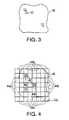
- FIG. 3shows a blow up image of the pixels 42 (only representative pixels 42 are shown) which make up the tooth image 40 of FIG. 2 .
- these pixelsare transformed into pseudo-pixels 44, as shown in FIG. 4 .
- each pseudo-pixel 44is made up of all or some of the real pixels within the area of the associated pseudo-pixel.
- Pseudo-pixels 44b shown in the figureillustrate, for example, how a pseudo-pixel can be generated from nine real pixels 42.
- FIG. 4also illustrates that an image can be made from either a real tooth 40 (resulting in a REAL IMAGE) or a reference shade 40 (resulting in a REFERENCE IMAGE).
- FIG. 9shows how pseudo-pixels can be arranged in a preferred embodiment in different patterns, automatically, depending upon which tooth is imaged.
- an incisor 200can have an arrangement of pseudo-pixels 202, as shown in the left-hand example, while a molar 204 can have an arrangement of pseudo-pixels 206, as shown in the right-hand example.
- such arrangementscan be made automatically in the system of this invention by informing the computer 14, and hence the software 50, to apply pseudo-pixels in the appropriate pattern.
- Such arrangementsassist in overall processing by ensuring appropriate pseudo-pixel placement.
- pseudo-pixelsneed not be contiguous, or aligned, such as shown by the arrangement of pseudo-pixels 206.
- the intensity and color associated with a pseudo-pixelare computed or otherwise formed as an average (or other statistical measure) of the actual pixels forming the pseudo-pixel.
- an actual image taken in the first step of the methodcorresponds to a rectangular tooth that is digitized at 300W by 350H resolution, i.e., having a total of 300x350 elements
- pseudo-pixelsare generated by data derived from all or some of the actual pixels located within the pseudo-pixel. For example, in a specific embodiment one can average the red, green and blue (RGB) components for each of the 2500 pixels within each pseudo-pixel to determine a reference RGB for that pseudo-pixel.
- RGBred, green and blue
- Those skilled in the artwill appreciate that other statistical measures or characteristics can be used, such as the mean "hue” measure of the pixels within a pseudo-pixel, or others.
- the RGB pixel valuesmay be converted into the Hue, Saturation and Intensity (“HSI”) color space by using known algorithms, such as the Gonzalez and Woods methods, as follows:
- the RGB color spacecan be represented as a simple cube, with R, G and B emanating from one corner along three perpendicular edges.
- the origin corner (0,0,0)is black, and the opposite corner (1,1,1) is white. All points along this line from corner to corner are shades of grey.
- the HSI color spaceis this same cube stood on the origin corner, with the Black White line being vertical.
- the black - white lineis the intensity axis, the hue is given by an angle from the intensity axis and the saturation is the distance from the intensity axis to the color point (i.e., the radius).
- the new VITAPAN 3D-Master Shade systemuses an L*a*b* Color Sphere to determine tooth shades based on Value, Chroma and Hue. It is possible to convert the RGB values to this color system, if necessary or desired.
- PSEUDO IMAGESare processed then into a "REFERENCE IMAGE".
- REFERENCE IMAGEis generated as an average (or other statistical measure) of the PSEUDO IMAGE series of images of the VITATM A2 shade guide. The measure in this example is obtained by averaging the R, G, B components for each pseudo-pixel of the A2 PSEUDO IMAGE series to determine an average RGB value for a pseudo-pixel of the REFERENCE IMAGE.
- the corresponding average valuescan also be determined for each pseudo-pixel of the PSEUDO IMAGE series; and, for example, an average hue (or other statistical measure of hue) can also be associated with each pseudo-pixel in the REFERENCE IMAGE.
- an average hueor other statistical measure of hue
- other color characteristicscan be used alternatively or in conjunction with the measure of RGB and/or hue. It will be appreciated that if only one PSEUDO IMAGE is made per shade, than that PSEUDO IMAGE defaults as the REFERENCE IMAGE since no other statistical combination is available.
- pseudo-pixelsare used in a preferred embodiment because they may reduce the processing load of the system, minimize storage requirements and also because they can simplify the task of aligning corresponding pixels from different images. Proper pixel alignment is important in order to ensure the integrity and accuracy of the statistical averages used in the formation of REFERENCE IMAGES. In this regard it will be appreciated that it is generally difficult to precisely align all pixels in several images taken from the shades of the same shade guide, unless there is extremely good control utilized in the image capture sequence. Using pseudo-pixels in accordance with the preferred embodiment reduces the total number of pixels per image and thus simplifies the task of aligning different images accurately.
- Pseudo-pixelsare even more important in later steps of the processing method of this invention. That is, although one has complete freedom to set up the optics and the camera, which together determine the magnification of a captured tooth shade (or tooth) image, when trying to "match" a REFERENCE IMAGE to an actual digital image of a patient's tooth, the actual image (hereinafter referred to as a SNAPSHOT) may be quite different in shape and size (either real size or apparent size due to magnification differences in the optics or camera CCD element size). As such, a "one-to-one" comparison between the SNAPSHOT and the REFERENCE IMAGE is difficult.
- Pseudo-pixelshelp in this respect because the SNAPSHOT can be scaled to approximate the REFERENCE IMAGE size, or vice versa; and the SNAPSHOT can also be processed into pseudo-pixels.
- the scaled and pseudo-pixel version of the SNAPSHOT imageis denoted as the "REAL IMAGE" hereinafter.
- Pseudo-pixels used in a preferred embodimentthus permit a convenient mechanism for comparing a REFERENCE IMAGE to a REAL IMAGE.
- each REFERENCE IMAGEpreferably includes a "bad pixel" routine where each pseudo-pixel in the PSEUDO IMAGE series is analyzed for bad pixels.
- a "bad pixel”means any real pixel corresponding to a defective CCD element or corresponding to an area with an unwanted artifact, e.g., reflection, in the digital image, or an area that contains "background” imagery (e.g., any pixel image not corresponding to the tooth or tooth shade).
- Any pseudo-pixel in the PSEUDO IMAGE which contains a bad pixelis preferably not utilized in the generation of the REFERENCE IMAGE.
- a REFERENCE IMAGEis made up as an average of three PSEUDO IMAGES, and yet one pseudo-pixel in one of the PSEUDO IMAGES contains a bad pixel, then in a specific embodiment the resulting pseudo-pixel of the REFERENCE IMAGE is either discarded, or computed only as an average of the other two associated pseudo-pixels of the PSEUDO IMAGES.
- FIG. 4illustrates bad pseudo-pixels 44a that contain pixels 42a, which are not part of the tooth image 40.
- Bad pixel routinesused in accordance with a preferred embodiment to detect such pixels and disqualify them from further processing. For example, if 5% or more of the pixels within a pseudo-pixel are "bad" (e.g., containing reflections or other unwanted data), then such pseudo-pixels are disqualified. Though not shown, other pseudo-pixels might be disqualified if for example reflections from the light ports cause unwanted reflections in the other pseudo-pixels image 40. In a preferred embodiment, such pseudo-pixels are deleted from inclusion in the REFERENCE IMAGE.
- the bad pixel routineneed only be implemented when capturing and generating REAL IMAGES. In that process, conditions such as lighting and other variables can create unwanted artifacts that should be eliminated from processing. In addition, when cameras are used in the field, one pixel might become defective over time; and REAL IMAGES later generated from the defective camera should be adjusted so that the pseudo-pixel which contains the bad pixel is not counted or utilized.
- areas of the tooth for which the color is to be evaluatedare predefined, allowing the analyzer program operating in accordance with this invention to batch-process the images.
- a sample imagecan be loaded into an Area Selection Editor program module, where adjustments can be made to user-selected (or predefined) areas of the tooth image. These defined areas are then applied to each image in turn, and the pixel colors within each area are analyzed.
- the method of this inventionproceeds to automatically select the area(s) of the sample for analysis, for example, by applying a general rule to locate the edges of the tooth in the image, and applying a predefined segmentation of the remaining area for analysis.
- the useris allowed to manually select an area of interest in the image, for example, using a computer mouse, as known in the art.
- the selected areais divided by using, for example, a grid overlay, as shown in Fig. 9 .
- a grid overlayAs known, each shade has a varying color content from top to bottom. Therefore, in accordance with this embodiment a more accurate analysis of the entire surface of interest can be made if color determination and matching is applied to the individual cells of the grid, as compared with corresponding area cells of the stored color reference model for each shade guide.
- various filtering operationscan be applied to the image, as known in the art. For example, filtering is applied to eliminate abnormalities such as lamp reflections or dark spots.
- maximum, minimum and average values for the R, G and B componentscan be determined over the area of interest and used to, for example, limit the variation from the average value to half way to the maximum and minimum values. This simple filtering operation has shown satisfactory results in actual testing, although alternative or additional filtering operations can be applied, as known in the art in order to obtain a standard image.
- a SNAPSHOT of a patient's toothis taken by the camera.
- the digital image of the SNAPSHOTis scaled, if necessary, to approximate the size of the corresponding REFERENCE IMAGE.
- SNAPSHOT pixelsare next processed into pseudo-pixels resulting in a REAL IMAGE containing pseudo-pixels, which substantially correspond to REFERENCE IMAGE pseudo-pixels.
- a bad pixel routinepreferably processes the REAL IMAGE to delete REAL IMAGE pseudo-pixels containing a bad pixel.
- the bad pixel routineis particularly important at the edges of the tooth image within the SNAPSHOT, where some pixels will certainly contain background (unless the camera and optics are arranged to capture only the tooth; however this is not efficient since effective matching between the REAL IMAGE and the REFERENCE IMAGE occurs when a larger area of the tooth is used in the comparison algorithms, which are defined in further detail below).
- the REAL IMAGEis compared (i.e., correlated) to each REFERENCE IMAGE in the database (e.g., there could be sixteen REFERENCE IMAGES corresponding to the A1-A4, B1-B4, C1-C4 and D2-D4 Vita Shades) via the correlation algorithm (hereinafter "Correlation Algorithm") described below.
- Correlation Algorithmthe correlation algorithm
- each pseudo-pixel of the REAL IMAGEis compared to each pseudo-pixel of the REFERENCE IMAGE; and a composite match number (“CMN") is created indicating how well the REAL IMAGE matches to that REFERENCE IMAGE.
- the composite match numbersare compared to one another and one of the REFERENCE IMAGES is selected as the "best fit" match to the REAL IMAGE.
- imagesare correlated on the basis of mathematical measure, i.e., an average, that is functionally dependent upon how many pseudo-pixels remain in an image (REAL or REFERENCE). That is, for any given correlation between a REAL IMAGE and a REFERENCE IMAGE, the number of pseudo-pixels for that comparison are used as a ratio for comparison to other correlation. This aspect of the invention is described in more detail below.
- the averaging technique discussed aboveis used only when, for example, more than 20-25% of the pseudo-pixels are disqualified for all comparisons. Accordingly, so long as there is a sufficient number of remaining pseudo-pixels for comparison, a direct comparison of these pixels can be made without resorting to averages. In a specific embodiment, a sufficient number is deemed to be about 75-80% of the total number of pseudo-pixels available for comparison. Other ratios can be used in alternate embodiments.
- Bad pixel routinesare generally known in the art and thus need not be described in much detail. It is sufficient to note that in accordance with this invention a pixel is determined to be “bad” if its light intensity or color values deviate by more than a certain predefined percentage from adjacent pixels known to be “good”. For example, if a pixel deviates by more than 30% from the light intensity of the neighboring 8 pixels, there is a good likelihood that this deviation is anomalous, i.e., due to a bad camera element or corresponding to an image border, and has to be discarded.
- a pseudo-pixelis validated only when it contains less than a certain percentage, i.e., about 5%, bad pixels of the total pixels making up the pseudo-pixel.
- bad pixelsare also not used in the statistical characterization (e.g., RGB) of the pseudo-pixel. Accordingly, in this embodiment if more than about 5% bad pixels exist for a pseudo-pixel, the pseudo-pixel is not used in further processing.
- each REFERENCE IMAGEis actually a matrix of vectors, each vector corresponding to a pseudo-pixel.
- the REFERENCE IMAGE corresponding to the A1 Vita Shadecan be assigned as vector Z A1 .
- each of the pseudo-pixels "PP"has three values for each of R, G and B values of the pseudo-pixel (actually, the RGB values are the statistically computed (e.g., averaged) composition of the images in the series for that REFERENCE IMAGE, if available).
- Subscripts 1-ndefine separate pseudo-pixels in the REFERENCE IMAGE. Those skilled in the art will appreciate that additional, other or different data can make up each vector, including hue data for each pseudo-pixel. Additionally, other vectors can be considered and processed in the correlation, such as hue and RGB values.
- each REFERENCE IMAGEmight have 20x20 pseudo-pixels which define the REFERENCE IMAGE. Therefore, "n" in the above matrix is 400.
- each pseudo-pixel "PI" of the REAL IMAGEbeing a vector of RGB form (or, like above, containing other or additional factors such as hue):
- CMNwithout the q-th pseudo-pixel; however, every other concurrent q-th pseudo-pixel valuation of CMN x in identifying the composite match number is also discarded, so that CMNs for all tooth shades can be compared correctly.
- Pcount xcorresponds to the number of common pseudo-pixels found between the REAL IMAGE and the vector Z x .
- Pcount xcan be different for each CMN correlation. For example, if the REAL IMAGE has 400 pseudo-pixels, all good, and REFERENCE IMAGE for A1 has 399 pseudo-pixels (e.g., one bad pseudo-pixel identified in the bad pixel routine), then Pcount A1 is 399. If however the REFERENCE IMAGE for B4 has 256 pseudo-pixels, then Pcount B4 is 256.
- the REAL IMAGEhas 256 valid pseudo-pixels - and in the unlikely event that the disqualified REAL IMAGE pseudo-pixels overlap with the coordinates of disqualified pseudo-pixels in the REFERENCE IMAGE - then Pcount B4 is still 256; however Pcount A1 is also 256 (assuming that the one bad pixel of REFERENCE IMAGE A1 corresponds to one of the disqualified pseudo-pixels in the REAL IMAGE). If the one bad pseudo-pixel in REFERENCE IMAGE A1 does not correspond to coordinates of one of the disqualified pseudo-pixels of the REAL IMAGE, a more likely event, then Pcount A1 is also 255.
- isolating the measure of closeness CMN in one of the above equationscan also be determined without the square root operation - as a minimum composite match number will still be identified for the same functional conditions and/or data.
- the process of determining Pcount xcan be made at any point. In a preferred embodiment, this process is initiated only after a certain percentage of pseudo-pixels are disqualified. For example, if after the completion of the bad pixel routine there remain 300 pseudo-pixels for comparison (in the example that 400 pseudo-pixels exist in each of the REFERENCE and REAL IMAGES), then a straight comparison can be made without the use of the Pcount x adjustment, because a significant percentage of the images can be compared (defining 75% as "significant"; other percentages can be used).
- colorimetric "laser-diode” measurementscan be used to generate a reflection trace for each pseudo-pixel.
- a laser diodeis "scanned” in wavelength so that a laser beam, scanned through a range of wavelengths, reflects off of each pseudo-pixel.
- This spectrophotometric-like trace information(for example containing reflectance per wavelength) can be collated with other such traces for other pseudo-pixels to generate a vector of such information.
- correlation between real and reference vectorsis used to determine a best-fit color match.
- the camera used for capturing imageshas a focal plane array with fewer detector elements as compared to typical high resolution arrays (for example those arrays with 640x480 elements, or megapixel digital cameras).
- an arrayhas a relatively small number of detectors, i.e., 20x20, 60x40 or others.
- Such a cameracan alleviate the need for pseudo-pixels, as defined above, since each real pixel generated from each detector covers a relatively large area of the tooth image. In effect, such a camera generates "pseudo-pixels" in each digital frame image. Since fewer detector elements are used in this embodiment, it will be appreciated that the camera's overall cost can be reduced.
- magnification opticsthat only utilizes a small portion of the camera's array in obtaining the image; however such an approach wastes pixel information which has already been collected.
- the shape of the grid of pseudo-pixels defining each toothis selected in a manner dependent upon how the tooth is positioned in the mouth.
- an incisor toothvery nearly maps to a shade guide; however, with reference to Fig. 14 , a posterior tooth does not, particularly relative to the image capture position of the camera.
- anterior teethare considerably more important than those in the posterior of the mouth.
- grid shapes and correlation algorithmscan depend upon tooth orientation within the mouth and/or upon generalized tooth shape.
- anterior teethwill have a (proportionately) larger number of pseudo-pixels than teeth in the back of the mouth for the same surface area.
- an image of a tooth or tooth shademay be analyzed by a flood fill algorithm to find the edges of the target tooth or tooth shade.
- a flood fill algorithmto find the edges of the target tooth or tooth shade.
- adjacent pixelsare considered only if that pixel is in a valid color range.
- the maximum extentis then recorded for the search in the X and Y directions, forming the outer limits of the grid.
- contrast changes in groups of pixelscan be considered and used to determine the extent; but a black border is easy to find.
- tooth shadesare not used per se in defining a patient's tooth color. Rather, in a specific embodiment, a grid of pseudo-pixels is generated for the patient's tooth; and these (pseudo-)pixels define the porcelain for respective regions of the tooth. Pseudo-pixels are not actually required; and actual pixels can also be used in this manner to define porcelain characteristics for each spatial location in the mouth. Reconstructive tooth material is then specified per pixel or pseudo-pixel. A data file generated from the SNAPSHOT or REAL IMAGE is then processed to specify reconstructive materials with spatial precision; as defined by pixels or pseudo-pixels.
- RGB valuescan be used to tolerance both the measurement and materials specification. For example, by associating error bars with each measure - e.g., R +/- ⁇ R, G +/- ⁇ G, B +/- ⁇ B, where the ⁇ quantities are defined within certain practical tolerance limits - reasonable tolerances can be achieved. Tooth shades operate similarly in that each shade results in a quantized color difference from every other shade; and thus the aforementioned tolerancing technique provides similar accuracy to the above-described correlation algorithm.
- Cameras of the type required for use with this inventionare generally known in the art and include, for example: INSIGHTTM, manufactured in San Carlos, California; CYGNASCOPETM offered by Cygnus Instruments, Inc., Goleta, California; VISTACAMTM and others.
- the system of this inventionuses a Welch-Allyn brand camera.
- camera systemsoffering full-color imagery, which are capable of capturing a range of sizes, i.e., from the size of a typical patient's tooth preferably to images of the patient's whole smile.
- the camerait is advantageous for the camera to supply a minimum 640 x 480 pixel image to the PC software at 24 bits per pixel (i.e., 8 bits for each of the red, green and blue (RGB) components), or preferably 30 bits per pixel.
- the system of this inventionuses ALARIS QUICK VIDEO TRANSPORT frame grabber, providing digitized images with at least 24 bits resolution.
- the softwarecan use a Twain protocol interface, as known in the art, which allows other cameras and frame grabbers to be tested without the need for a change of software.
- images captured by the cameraare displayed on a monitor screen to provide instantaneous feedback to the system operator.
- the resolution of the camerais specified in terms of the Minimum Resolvable Color Difference that the complete system is able to achieve. This can be specified, for example, as the two RGB values of the two closest shades the system is required to differentiate.
- the Chromoscop Shades 430 and 440can be used to this end.
- the systemshould be able to differentiate between about 80 or more different shades.
- Another requirementis that the system should be able to produce repeatable images. That is to say that images of the same tooth taken at the same session should not have a ⁇ i of not more than 0.1, which is the amount needed for the eye to perceive a difference.
- the camera used in the system of this inventionis a CMOS imager.
- a stand-alone camera containing its own light sourcecan be used, as explained below.
- the cameracan be battery powered.
- the camerasits on a holder containing an inductive battery charger when it is not in use.
- the camerawhen mounted on the charger the camera can be coupled via an isolation sleeve (to be explained below) to a calibration target, for example, made of porcelain.
- the output of the camerais supplied to a digitizer (such as a Sony digitizer) enabling convenient digital storage of the image.
- a digitizersuch as a Sony digitizer
- the output of the cameracan also be supplied to a frame grabber in a PC. Both options can be used in a specific embodiment.
- the output of the cameracan be supplied directly to a monitor (preferably positioned close to a surgery chair) and provide a digital output to a PC, which then need not be close to the patient.
- the outputcould be USB-type, or IEEE 1394.
- the digital output of the cameraalso provides the opportunity to control the camera from a PC.
- FIG. 1shows a system 10 constructed according to a preferred embodiment of the invention.
- a solid state (or intra-oral) camera 12connects to a computer 14 via a PC card 16 to capture images through a wand 18.
- the solid state camera 12includes a detector array 12a including an array of detector elements 12b, which generate pixels in the digital images (e.g., SNAPSHOTS) captured by the camera 12.
- internal optics within the wand 18 and/or camera 12permit the capture of an image of a target object 20 (for purposes of illustration, target object 20 is shown grossly over-sized as compared to other elements in FIG. 1 ) by the array 12a.
- relay optics 18a within the wandrelays an image to the array 12a.
- a protection sleeve 22, discussed in further detail below(also grossly oversized for purposes of illustration), preferably extends from the wand 18.
- the opticsprovide an optical conjugate between the array 12a and the target object 20 through well-known imaging techniques. Light captured from the target object 20 enters the wand 18 for transfer to the camera 12 through an entrance aperture window 26.
- the wand 18generates light 19 to illuminate the target object 20 through light ports 28.
- light from the outside 30 of a sleeve 22is not permitted to illuminate the object 20 so that control is maintained; and thus the sleeve 22 shields the target area 20 from illumination by outside sources 30 (e.g., ambient room lighting).
- An aperture 32 within the center of the end piece 34 of the sleeve 22is where the tooth or tooth shade are placed so that a SNAPSHOT (i.e., a digital image of the tooth or tooth shade) can be made.
- SNAPSHOTSare processed to form REAL IMAGES (from real teeth) or REFERENCE IMAGES (from tooth shades or porcelains, etc.).
- a black border 36 around the aperture 23provides a good reference around which the tooth or tooth shade are discernible within the digital image of the target area 20.
- the remaining area 38 about the border 36 and within the end piece 34is preferably a white reference sample, equally reflecting all light 19 from the light ports 28.
- digital images from the camera 12are sent to the computer 14; and processing software 50 within the computer 14 processes these images to generate, e.g., a CMN for each REAL IMAGE relative to the REFERENCE IMAGES.
- the software 50processes the CMNs to locate the lowest value CMN, indicating a match; and communicates the associated shade of that lowest CMN to the user via signal line 52.
- other processing algorithmscan be developed to determine a best-fit match without departing from the scope of the invention.
- FIG. 2A representative digital image 31 captured by the camera 12 is illustrated in FIG. 2 , showing an image 36' of the border 36, an image 38' of the reference sample 38, and a tooth image 40.
- the entire image 31covers the target area 20 of FIG. 1.
- FIG. 2also illustrates obvious regions 31 of the image 31 that would generate bad pixels since such regions do not contain tooth imagery but rather other background imagery (e.g., the patient's gum).
- FIG. 3shows a blow up image of the pixels 42 (only representative pixels 42 are shown), which make up the tooth image 40 of FIG. 2 .
- these pixelsare transformed into pseudo-pixels 44 of FIG. 4 .
- Each pseudo-pixel 44is made up of all or some of the real pixels within the area of the associated pseudo-pixel 44.
- Two pseudo-pixels 44billustrate, for example, how a pseudo-pixel can be generated from nine real pixels 42.
- FIG. 4also illustrates that an image can be made from either a real tooth 40 (resulting in a REAL IMAGE) or a reference shade 40 (resulting in a REFERENCE IMAGE).
- REAL IMAGES and REFERENCE IMAGESare correlated to find the composite match number (CMN) as described above.
- FIG. 5shows another embodiment of an end piece 98 used in accordance with a specific embodiment, that mounts to, or is made integrally with, the end of the sleeve (e.g., the sleeve 22, FIG. 1 ) and which has a series of tooth shades 100 disposed in the end piece 98, so that for each target 102 (e.g., the tooth or tooth shade), all relevant manufacturing shades are provided in the same digital image, thereby preventing color contamination or other anomalies caused by time delay.
- each shade 100is processed as a REFERENCE IMAGE and the tooth 102 is processed as a REAL IMAGE relative to those REFERENCE IMAGES to find a CMN.
- a black border 104surrounds the tooth aperture 116 and tooth 102.
- the remaining area 116 about the border 104 and in the end piece 98is a reference area.
- the reference area 116is a white reflecting region with can be sampled by detectors that image that region 106. Further examples of the use of reference area are discussed below.
- the system of the inventionhas an isolation sleeve serving to reduce variations in the images captured and processed by the system, and in particular to eliminate light contamination from external sources.
- the isolation sleevepreferably keeps the reference shade and the actual tooth at a set distance from the illumination source and the camera optics.
- the sleevealso preferably sets the angle of illumination between the source and the tooth so as to reduce reflections. More particularly, the REFERENCE IMAGES and the REAL IMAGE are preferably taken at the same illumination intensities, at approximately the same distance, and without substantial specular reflections from the source.
- the sleeveshields the camera detector from imaging outside light and instead utilizes internally generated light (i.e., internal to the camera, for example, or associated with an intra-oral wand attached to the camera) that can be controlled.
- the sides (or side) of the sleeveare coated in a specific embodiment with a black material (e.g., a paint or a black mat paper, or black felt), which reduces reflections along the sleeve to the tooth or reference shade.
- a black materiale.g., a paint or a black mat paper, or black felt
- target arearefers to the image gathering location that the system of the invention (i.e., that region captured by the camera's detectors), including the REAL or REFERENCE IMAGE, as defined above.
- FIG. 6shows one end of wand 130 and a sleeve 132 constructed according to a specific embodiment of the invention.
- the wand 130connects to a solid state camera (not shown, for purposes of illustration) to collect digital images of the target region 134 at the end of the sleeve 132.
- the target region 134includes an aperture (not shown) for imaging a tooth therein.
- Light 135 from the camera or wand 130exits the wand 130 at optical aperture 136 to illuminate the target region 134.
- the sleeve 132 used in the camera system of the present inventionincludes an accordion-like exterior, which permits soft placement of the end of the sleeve onto the patient's tooth.
- a sleeveis not entirely rigid so that the sleeve 132 can make contact without concerns about damaging the tooth.
- the outer portion of the sleeve 132 in this embodimentthus acts similar to a spring, and an inner structural member within the sleeve sets the final source-to-tooth distance once the outer sleeve/spring compresses to the desired location.
- the accordion-like sleeve 132compresses between the target region 134 and the wand 130, as shown by compression arrow 138.
- a user of the wand/sleeve 130/132pushes the sleeve 132 to the patient's tooth, and the sleeve 132 compresses to provide comfortable (i.e., non-rigid) contact with the tooth.
- the sleeve 132is spring-like to provide some force opposing compression.
- This forceincreases until there is an interaction between the sleeve 132, and/or the end piece of the sleeve 132 (i.e., the part of the sleeve at the target region 134), and the rigid structural member 140 within the sleeve 132.
- the member 140stops compression at a fixed location so that a set distance is achieved from the aperture 136 and the target region 140; and so that a repeatable image size is attained.
- the camera system of this inventionincludes a light source that illuminates the target area.
- the sleeve 132can be made to rotate so that images are gathered from difficult locations in the mouth.
- the light sourceis tied to fiber optics which rotate with the sleeve so that regardless of sleeve position the source-to-target area remains approximately fixed.
- the cameraincludes optics, such as image collection optics and/or an entrance window. In an embodiment including this feature, the camera optics is tied to fiber optics, so that images are captured effectively regardless of the position of the sleeve.
- the sleeve used with the dental camera system of the present inventionincorporates imaging optics which relay the tooth image through a Lyot stop, to prevent passage of unwanted light energy to the camera detectors.
- the sleeveincorporates baffling - such as "two-bounce" optical stray light baffling - to reduce or substantially eliminate stray light from external sources to the desired tooth image area.
- FIG. 7shows illumination arrangement in a preferred embodiment of the system of the invention.
- the source 150 of the illuminating wand 152(connected to the solid state camera, not shown) is angled from the target area 154.
- the sleeve 156 connected to the wand 152is arranged adjacent to a patient's tooth 158, so that digital images can be taken of the tooth 158 (according to the practices discussed herein) through the wand's optical entrance aperture 160.
- FIG. 7also shows how light 162 emitting from the source 150 travels in a generally specular direction 164, reflecting off the tooth 158 into a direction 166 that is away from the aperture 160.
- opticse.g., fibers and/or relay lenses
- FIG. 7also shows how light 162 emitting from the source 150 travels in a generally specular direction 164, reflecting off the tooth 158 into a direction 166 that is away from the aperture 160.
- opticse.g., fibers and/or relay lenses
- FIG. 8shows another embodiment of a sleeve 168 constructed according to the invention to reduce passage of light 171 into the wand's entrance aperture 169 from sources 170 away from the target object (e.g., the tooth 172).
- the sleeve 168is especially useful in imaging the tooth 172 without adjacent proximity to the sleeve 168, as illustrated in FIG. 8 .
- the sleeve 168includes baffles 168a known in the art, which require at least one "bounce” and preferably two bounces of the light 171 prior to gaining access to the entrance aperture 169, thereby significantly attenuating "out of field" sources 170 (i.e., those unwanted sources which might influence the color measure, e.g., room lighting). For simplicity, in this illustration the wand and solid state camera are not shown. Baffles 168a can be placed within other sleeves shown herein to improve out-of-field stray light rejection.
- the sleeve used in the dental camera system of this inventionincludes a reference sample disposed at the end of the sleeve, near the target area, so that: (a) color comparison information can be obtained; and/or (b) the camera has sufficient reflective surfaces from which to effectively trigger the camera's auto-brightness and/or auto-color features.
- certain cameras available on the marketinclude electronics and software which automatically adjust brightness and/or color in a digital image. Preferably, in this embodiment such features are disabled.
- the reference sampleis sized so that a sufficient reflection area is generated at the end of the sleeve, whereby the camera can operate to capture good color images.
- the sampleshould be sized so that RGB values vary in a controlled or calibrated manner throughout the reasonable tooth shade reflections (e.g., throughout all Vita Shades).
- one preferred embodiment of the inventionutilizes the reference sample to obtain a color reference used to reduce variations in the digital image.
- Coloris based on “reflection” - that is, what the camera sees at the target area is based on reflection of whatever source illuminates the target.
- the sourceis limited to the camera's illuminating source, thereby eliminating other sources and color variations that are not controllable (e.g., the ambient lighting in a building). It is well known that a black body absorbs visible light; and a white object reflects the light.
- the reference sampleis as white as possible so that it exhibits very little color (and particularly, the sample reflects light equally in the visible light range from between about 400nm to 800nm).
- the following processoccurs:
- the reference sample compensation algorithm described aboveis used in a specific embodiment to compensate for certain variations.
- the auto-brightness feature of certain cameraschanges the color of the light emitted from the camera (this is sometimes referred to in the art as the color temperature).
- the emitted RGBis not known except for the reference sample, which reflects the source light back to the camera detectors. A good reference sample will thus reflect nearly all colors equally. Since one is interested in differences between REAL IMAGES and REFERENCE IMAGES, the real concern involves differences and not absolute colors.
- the reference sample compensationthus also compensates for image acquisition changes which occur over time.
- the sourcemay emit more or less light, over time, even over several minutes or hours; and it would be desirable to eliminate such variations to increase the sensitivity to color comparisons.
- the passage of time during an image acquisition sequenceonly adds to the variability in the measurement: the source color temperature may change, the detector sensitivity or gain may change, etc.
- the white referenceis integrated to find REF RGB, per frame.
- REF RGBis then subtracted from each pixel RGB in the image (or the other way, i.e., image RGB subtracted from REF RGB, as long as consistent throughout every measurement).
- REF RGBis subtracted from pseudo-pixels; but preferably REF RGB is subtracted from real pixel RGBs.
- the sleeve used with the dental camera system of the present inventionis formed in the following way.
- a central apertureexists preferably in the middle of the target area (e.g., an object such as a tooth or shade is placed at the aperture).
- Surrounding the central apertureis a black border, to provide high contrast at the edges of the target object.
- a target object such as a toothis thus readily defined and discerned within the black border.
- the aperturealso fixes the size of the image for the tooth or tooth shade.
- the amount of white reference sample in the target areacan be chosen experimentally.
- the average mid point in the auto-brightness (if operating)is obtained so that on average REF RGB changes little.
- the size of the white sample in the target areais adjusted in area until REF RGB is minimized for all shade values, e.g., A1-A4, B1-B4 and so on.
- the auto brightness control on the cameraadjusts to higher gain to 'balance' the intensity of the image, causing the reference and sample parts to saturate in the red and green.
- the walls of the sleeveare selected mat black to eliminate reflections, but the facing plate containing the target area is bright to force the camera gain downwards, out of non-linear color operability.
- the camera's auto featuresare turned off (and at least any white balance is set to manual).
- the reference sampleis made of a light colored felt material.
- the sleeve wallsare made of a felt material.
- the felt materialhas elements which extend away from the material producing more of a lambertian surface. Such surfaces are preferred as they reduce unwanted specular reflections.
- the sample referenceproduces an excellent image when it is not specular.
- a black velour papercan be used in the sleeve, such as by JL Hammett Co.
- FIG. 10illustrates a non-contact re-imaging system 250 used in accordance with another embodiment of the present invention to image a target tooth 252 without contact between the tooth 252 and a sleeve 254.
- Optics 255reimage the tooth 252 internal to the sleeve 254, at internal image 256, and a Lyot stop 258 is used to reduce unwanted stray light entering the aperture 260 to the camera (not shown).
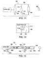
- FIG. 11illustrates a non-contact re-imaging system 300 used to image a target tooth 302 to a digital camera 304, and without contact between the tooth 302 and the system 300 or camera 304.
- this reimaging system 300can be made in several forms, in one embodiment the system 300 includes a sleeve 306 that permits hand-held manipulation into a patient's mouth to capture the digital image of the tooth 302.
- optics 308reimage the tooth 302 internal to the sleeve 306, at internal image 310, and a stop 312 is used for color referencing in analyzing the tooth color. Stop 312 forms an aperture defined by edge 312a.
- Region 322illustrates one digital image 320, as taken by camera 304, of the tooth 302 and the inside view of stop 312.
- the region 322defines that region inside the patient's mouth that is not the patient's tooth 310.
- Region 324consists of a color reference which is used as described herein to relate and compare to color pixels of the digital image of the tooth image 310, so as to better define tooth color. Region 324 is preferably inside of stop 12.
- system 350 of FIG. 13shows one system of the invention to reimage a tooth 352 to an internal image 354 for reimaging into a digital camera 356.
- camera 356takes SNAPSHOTs of the tooth 352, for color analysis.
- Optical element 358images the tooth into optical fiber bundle 360, which relays the image from one side 360a to the other side 360b of the bundle 360, as known in the art.
- Optical elements 362provide for reimaging to form the internal image 354 at the stop 364.
- the stop 364has a reference color disposed thereon, facing camera 356, so that a reference color image is attained such as in FIG. 12 .
- Fiber optic bundle 366relays the image 354 from side 366a to 366b, and exit optics 368 provides for relaying the tooth image to the camera 356.
- One convenient feature of system 350is that fibers 366, 360 can be flexible; and a sleeve 370 can support these elements to provide a hand-held wand that can be inserted into a patient's mouth to acquire the image.
- Camera 356can provide its own light source 356a which generates light 356b back along the optical path taken by tooth image 354.
- source 356acan be carefully selected for its color characteristics to facilitate tooth color detection; and further light 356b can illuminate stop 364 inside the sleeve or wand 370 so that the camera 356 can detect and compare its color to the tooth's color image 354.
- FIG. 14shows certain tooth restorations and decays, which illustrations can help understand more fully aspects of the invention discussed above.
- a healthy tooth, free from any decay with no current restoration(“restoration” is any part of a tooth that is replaced with a material that allows the tooth to remain in the mouth as a functioning and whole structure) is referred to as a "virgin” tooth.
- preventative treatment and servicesfluoridated water, fluoride treatments, sealants - which are unfilled resins that are bonded into deep grooves of posterior or back teeth to prevent decay in those areas
- 50% of American children by age 12have occlusal decay (decay in the top, or biting surface) in permanent molars which erupted or came into their mouths at age 6.
- Typical progression of decay in a toothis as follows: Following C.V. Black's classifications, a tooth can require a restoration in the following positions:
- the decayed portion of the toothneeds to be removed. This is achieved through the use of a handpiece (drill). Once excavation of decay is complete, the remaining tooth structure is evaluated for restoration possibilities. A "filling" is placed if 50% or more of the tooth remains, with the stress-bearing areas of the tooth remaining intact (such as cusps and walls of the tooth which are active in biting and chewing process). If these areas of the tooth are compromised, a laboratory-processed restoration is required.
- the tooth surfaceis etched with a cleanser (typically 37% hydrophosphuric acid), rinsed, and treated with an adhesive, which is bonded to the tooth by use of a curing light - a light with a wand attachment that is about 11 - 13 cm in width and emits a light in the range of 400-500 nanometers.
- the materialis then placed into the cavity by hand instruments or via dispensing through a carpule/cartridge system in a syringe. The material is somewhat condensed into place at 2-3 mm intervals, and light cured in between.
- the restorationis polished and contoured using finishing burs (tips) on the handpiece (drill).
- the toothrequires a lab fabricated restoration, such as an inlay, onlay or crown, further steps need to be taken (Inlay being a Class 2 restoration NOT including cusps, onlay being a Class 2 restoration including cusps, crown being full, or total coverage of the tooth).
- the toothis shaped to make the final shape not have any undercuts, with walls as parallel as possible for retention purposes.
- an impression, or moldis taken of the tooth, which is in a material that remains accurate despite temperature changes, moisture, pouring stone into the mold and removing it several times.
- An impression of the opposite arch of teeth, or opposing archis taken also so that the technician can articulate, or put together the two arches and simulate the patient's mouth or bite.
- a registration of such a bitecan be taken also and sent with the case. So that the things sent to the lab for such a case are: impression of the tooth to be restored and adjacent teeth, model or impression of opposing teeth, and possibly a bite registration.
- FIG. 14Those skilled in the art should appreciate that the invention to determine the appropriate color shades of the tooth as illustrated in FIG. 14 can be accomplished by the methods herein, and/or by systems disclosed in the several figures. Using a wand of the invention, furthermore, various teeth (as in FIG. 14 ) can be acquired for digital evaluation. In accord with the invention, digital files of patients' teeth can be stored in memory of computer 14, FIG. 1 , for a permanent record. A patient can then be evaluated over time for color changes.
- VITATM Shade guideis often discussed herein, it should be apparent that other shade guides and porcelains can be stored as REFERENCE IMAGES and compared to REAL IMAGES in alternative embodiments of this invention.
- Computer memorycan store a large number of images, even from different manufacturers, so as to provide the optimum color fit to a patient's tooth.
- IVOCLARhas one suitable shade guide, as well as various materials of porcelains, ceromers, polymers, and others.
- a databasecan store REFERENCE IMAGES for match correlation to REAL IMAGES.
- the inventionperforms a conversion to other manufacturer shades and or porcelains so that alternative laboratories can be used without undue concern for manufacturer alliance.
- a conversion between known shade guidesis provided for increased lab selectivity. It will be appreciated that the conversion of digital images involves mapping from one set of color coordinates to another, which procedure is well known in the art and need not be considered in further detail.
- one major problem due to auto brightnessis that if there is not enough light material in the image, the auto brightness turns the gain up too high, and the R and G values saturate in the sample.
- the referencecan saturate in places. This can be compensated some by using an end plate at the end of the sleeve that will be all white but with the black border round the sample aperture.
- a reference color areacan be included in one corner so that the camera adjusts brightness for the constant white area leaving the reference and sample somewhere in the middle of the operable RGB ranges.
- an average of the reference sampleis used. Specifically, over the range of images taken, an average REF RGB (denoted "AVE REF RGB”) is determined for the reference sample. For each individual image, the difference is calculated between the REF RGB and the AVE REF RGB. This delta RGB is then added to the image RGB to correct for any compensation in the camera. Thus if the image is brighter than the average image, the difference is subtracted from the sample values and vice versa.
- REF RGBdenoted "AVE REF RGB”
- the reference sleevehas an end plate which contains all tooth shades for a given manufacturer (so that one sleeve is used for a particular manufacturer). Any image therefore acquires the sample tooth as well as all the tooth shades; and image processing commences on the one digital image. This is advantageous in that camera color drift is compensated for since all images are taken at the same time.
- APPENDIX Acontains, for disclosure purposes, non-limiting source code for use with certain aspects of the invention.
Landscapes
- Physics & Mathematics (AREA)
- Engineering & Computer Science (AREA)
- General Physics & Mathematics (AREA)
- Health & Medical Sciences (AREA)
- Spectroscopy & Molecular Physics (AREA)
- Theoretical Computer Science (AREA)
- General Health & Medical Sciences (AREA)
- Computer Vision & Pattern Recognition (AREA)
- Life Sciences & Earth Sciences (AREA)
- Multimedia (AREA)
- Artificial Intelligence (AREA)
- Evolutionary Computation (AREA)
- Veterinary Medicine (AREA)
- Oral & Maxillofacial Surgery (AREA)
- Software Systems (AREA)
- Medical Informatics (AREA)
- Computing Systems (AREA)
- Public Health (AREA)
- Animal Behavior & Ethology (AREA)
- Epidemiology (AREA)
- Dentistry (AREA)
- Databases & Information Systems (AREA)
- Immunology (AREA)
- Pathology (AREA)
- Mathematical Physics (AREA)
- Data Mining & Analysis (AREA)
- Biochemistry (AREA)
- Analytical Chemistry (AREA)
- Chemical & Material Sciences (AREA)
- Bioinformatics & Cheminformatics (AREA)
- Bioinformatics & Computational Biology (AREA)
- Evolutionary Biology (AREA)
- General Engineering & Computer Science (AREA)
- Dental Tools And Instruments Or Auxiliary Dental Instruments (AREA)
- Endoscopes (AREA)
- Image Processing (AREA)
- Image Analysis (AREA)
- Investigating Or Analysing Biological Materials (AREA)
Abstract
Description
- The invention is directed to methods and devices for tooth shade determination using digital signal processing. More specifically, the invention is directed to computer-based system and methods for analyzing color images of one or more teeth and comparing them to known tooth shades for use in certain clinical or cosmetic procedures.
- There has been a shift in recent years in dentistry from a philosophy of drilling and filling to one of prevention and cosmetics. Due to concerns about the visual appearance of their teeth, many people undergo clinical procedures to enhance their smile or to correct certain dental defects. Clinical or cosmetic procedures of this type generally involve the modification of tooth shape, alignment and, more recently, color.
- A necessary step in the modification of a patient's tooth color is to determine the "shade" of an existing tooth. Such a determination is useful, for example, to patients seeking a whiter, brighter smile, who frequently want a record of their existing tooth color so they can make a before and after comparison. Shade determination is even more important when reconstructive work is done, since one goal of the process is to achieve a natural appearance. To this end, it is necessary to know the existing tooth shade so that it can be accurately matched with the new restoration.
- At present, with respect to tooth color modification, most dentists utilize standardized shade guides created by companies which manufacture reconstructive materials. One well-known shade guide is the VITA™ shade guide, which includes sixteen different shades. Other, shade guides used in practice include the guides provided by BIOFORM™ and SR-VIVADENT™.
- For the most part, the existing shade guides are still utilized in a rudimentary fashion. The guide itself is a plastic plate with a plurality of removable color tabs that are shaped like a tooth, e.g., the front tooth. Typically, to assess a patient's tooth shade, a dentist removes one or more of the colored tabs and holds them up to the patient's tooth to "eyeball" the closest match. Understandably, this approach sometimes fails, in part because of the need for a subjective assessment by the dentist, who may not be sufficiently qualified for the task.
- Another problem with the currently prevailing procedure is that once the tooth shade is determined, the information must be communicated correctly to the lab that makes the crown, bridge or denture. As known in the art, in bonding or filling a tooth, for example, the composite materials required for the restoration are specified within the range of the shade guide, e.g., one of sixteen shades for the VITA™ range. Errors in the determination of the tooth shade, or the communication of the determined shade to the lab will result in a poor shade match for the patient. For example, some dentists use uncommon shade guides, thereby leaving it to the lab technician to eyeball and convert the shade information to a VITA™ standard shade (since porcelain is often made from the VITA™ shade guide). This too can result in improper shade matching.
- The process for selecting the porcelain for a particular tooth shade illustrates the difficulty in assessing and manufacturing the correct color match. If, for example, a crown of VITA™ shade A3 is desired, porcelain is built by hand with a paint brush onto a model of the tooth to be restored. The porcelain is built in layers on the model to achieve translucency and natural appearance. Each layer has a particular color and intensity associated with it. To generate shade A3, the technician follows a "recipe" that is given by the manufacturer VIDENT™, requiring a different shade for each layer of porcelain applied. If a doctor asks for a shade that is not a VITA™ standard shade, the technician typically seeks to achieve that shade by combining different porcelain shade combinations together, to increase or decrease the chroma, hue and value of the shade.
- To further complicate the color-matching process, some dentists are simply not skilled in taking and determining shade information: Therefore, these dentists sometimes send their patients directly to the lab where the technician can determine the shade information. Alternatively, these dentists sometimes have a technician come to their office. In either event, there is, at times, one more level of subjective uncertainty injected into the correct match and determination of a patient's tooth shade. It was apparent, therefore that there is a need for improvements in this area.
- In the prior art, several attempts have been made to measure tooth shade. Such prior art includes, without limitation, the following patents and publications, each of which is incorporated by reference as providing useful background information:
JP 4-338465 by Kazeo Eto JP 4301530 by Kisaka U.S. Patent No. 3,986,777 ;U.S. Patent No. 4,247,202 ;U.S. Patent No. 4,414,635 ;U.S. Patent No. 4,518,258 ;U.S. Patent No. 4,547,074 ;U.S. Patent No. 4,623,973 ;U.S. Patent No. 4,654,794 ;U.S. Patent No. 4,692,481 ;U.S. Patent No. 4,836,674 ;U.S. Patent No. 4,881,811 ;U.S. Patent No. 5,012,431 ;U.S. Patent No. 5,124,797 ;U.S. Patent No. 5,231,472 ;U.S. Patent No. 5,240,414 ;U.S. Patent No. 5,313,267 ;U.S. Patent No. 5,343,267 ;U.S. Patent No. 5,373,364 ;U.S. Patent No. 5,383,020 ;U.S. Patent No. 5,690,486 ;U.S. Patent No. 5,759,030 ;WO 86/03292 WO 91/02955 - Generally, the attempts to measure tooth shade, as disclosed in the illustrative prior listed above, fail for various reasons, including primarily color contamination due to reflection and/or tooth translucency. In addition to inconsistent and sometimes inadequate and unreliable tooth shade determination, methods and devices disclosed in the prior art also have other limitations. For example, prior art using colorimeters often samples a single tooth location in attempt to analyze its color. Such an approach, however, fails to adequately characterize the entire spatial extent of the tooth, much less address the issue of matching the shade of one tooth to the shades of adjacent teeth.
PCT Application WO97/01308 U.S. Patent No. 5,766,006 ("the '006 patent") addresses many problems associated with the prior art. In particular, it discloses a camera that connects to an electronic shade analyzer system. The camera captures a digital color image of a tooth and compares that image to a stored plurality of tooth shades. Once a match is determined, the matching tooth shade is communicated to a user of the system, so that the desired tooth can be constructed. The methodology disclosed in the patent also includes the specification of fractional tooth shades. It will be appreciated that the approach discussed in the '006 patent is a substantial improvement over the prior art at least in terms of removing several levels of subjectivity.- Despite the significant advances achieved over the years, it is perceived that there is a need for improvements in several important areas. For example, these areas include the methods for digital signal processing which minimize the probability of matching errors due to various system imperfections. Another area where further improvements are desirable is the data capture process. By means of an example, it will be appreciated that it is very difficult to capture information about a tooth or groups of teeth that is independent of the lighting conditions, or the particular camera used. Accordingly, there is a need for improvements in several areas related to optimal analysis and processing of tooth shades.
- The invention relates to a computerised method for matching a tooth shade with a tooth according to claim 1. specific embodiment the camera is equipped with a sleeve and illumination subsystems that help reduce the variations in the color of digital images due to external factors.
- More specifically, the invention is a method for associating a tooth shade relative to a tooth, comprising: providing a digital image of the tooth, the digital image having pixels; processing the digital image to generate a REAL IMAGE formed of pseudo-pixels, at least one of said pseudo-pixels comprising two or more pixels of the digital image; correlating the generated REAL IMAGE with two or more REFERENCE IMAGES representing tooth shades to determine which tooth shade most closely matches visual characteristics of the tooth. In specific embodiments, the method of this invention further comprises the steps of capturing digital images of two or more tooth shades, and processing the captured digital images to form said two or more REFERENCE IMAGES, which can be color images.
- In another specific embodiment, the step of processing the digital image of the tooth comprises dividing the digital image into segments forming said pseudo-pixels, which can be based on the shape of the tooth, and need not be contiguous. In a preferred embodiment, the step of processing the digital image comprises determining pixels, the values for which are outside a pre-determined range compared with values of adjacent pixels, and excluding such pixels from further processing. In other embodiments the step of correlating comprises computing a closeness measure.
- In another aspect, the invention is a method for determining color characteristics a patient's tooth, comprising: providing a digital image of the tooth, the digital image having pixels; dividing the digital image into segments, each segment forming a pseudo-pixel comprising one or more pixels of the digital image; computing color characteristics of each pseudo-pixel based on the corresponding one or more pixels of the original image; and storing the computed color characteristics in a computer memory.
- These and other aspects of the invention should be more apparent from the following detailed description and drawings in which:
FIG. 1 illustrates a shade analyzer system for capturing images in accord with a specific embodiment of this invention;FIG. 2 shows a representative image captured by the system ofFIG. 1 ;FIG. 3 shows a representative image made up of pixels as captured by detector elements of the system in accord with the invention;FIG. 4 illustrates processing of the image ofFIG. 3 using pseudo-pixels, in accord with one preferred embodiment of the invention;FIG. 5 shows an end piece constructed for use with the system inFIG. 1 , for simultaneous processing of an actual tooth image and various reference tooth shades;FIG. 6 illustrates a compression sleeve constructed according with a specific embodiment of the invention for capturing high-quality tooth images;FIG. 7 illustrates a source-to-tooth illumination, for improved image capturing in accord with one embodiment of the invention;FIG. 8 illustrates baffling and stray-light rejection within a sleeve in a specific embodiment of the invention;FIG. 9 illustrates different pseudo-pixel imaging mechanisms, optionally dependent upon tooth shape characteristics, used in accord with the invention;FIG. 10 illustrates a non-contact tooth imaging system, with stray light rejection, constructed according to a specific embodiment the invention;FIG. 11 illustrates another embodiment of a non-contact tooth imaging system in accordance with the present invention;FIG. 12 illustrates a digital image of a tooth;FIG. 13 illustrates a system for reimaging a tooth; andFIG. 14 illustrates various tooth decay patterns and restorations that can be addressed in accordance with the present invention.- A number of different aspects of the invention are disclosed. For clarity of presentation, these aspects are organized and described below in sections which generally correspond to the methods and the system of the present invention. This organization of the preferred embodiments is not intended to be limiting in any way.
- With reference to
Fig. 1 , a solid state camera 12 (e.g., a CCD camera coupled to a PC board, or an intra-oral camera) is utilized to capture one or more images of each known conventional tooth shade. Tooth shades used to this end may correspond, for example, to the VITA™ Shade guide, or a shade guide corresponding to a porcelain by another dental products manufacturer. By way of example, a first series of images taken in accordance with the invention corresponds to sequential images of the A1 shade by Vita, a second series of images corresponds to sequential images of the A2 shade by Vita, and so on. In accordance with the invention, captured image series of the known tooth shade guides are properly labeled and then stored onto the hard disk of the computer, or other suitable storage device for further analysis.FIG. 2 illustrates a representativedigital image 30 captured by thecamera 12. - As known in the art, each digital image has a plurality of picture elements, i.e., "pixels", corresponding to the elements of the solid state camera and representing the light intensity and color properties of a given spatial location on the tooth. The distance between adjacent pixels in the image is determined by the spatial resolution of the camera. For example, an image of a tooth shade (or a human tooth) can be made up of 300 pixels in width across the tooth and 350 pixels in height. In human teeth, any given tooth is approximately the same size, give or take a couple of millimeters, for all people. For example, most central incisors usually measure between 9-11 mm in width, and somewhat greater in length It is clear therefore that for a given spatial resolution of the camera, in accordance with this invention, an image of a tooth can be taken knowing the approximate number of pixels corresponding to the tooth in the image. Thus, in the example above, 1 mm of the tooth width may be represented by 30 pixels. It will naturally be appreciated that the tooth image is typically not rectangular, and that pixels at the
corners 41 of an image may correspond to the background (i.e., the region outside of the tooth) and not of the tooth ortooth shade 40. SeeFIG. 2 for further illustration. - As indicated above, in a specific embodiment of the method of this invention, a single digital image can be captured for each tooth shade or actual tooth. Those skilled in the art will appreciate, however, that taking a series of images per shade is preferable, since it reduces the risk of image anomalies, as explained in further detail below.
- In a second step of the method of this invention, each image or each image in a series is processed into a "pseudo" reference image (hereinafter PSEUDO IMAGE) made up of pseudo-pixels. As used in this disclosure, pseudo-pixels correspond to groups of pixels covering specific areas (e.g., rectangular or square) of the image plane.
FIG. 3 shows a blow up image of the pixels 42 (onlyrepresentative pixels 42 are shown) which make up thetooth image 40 ofFIG. 2 . In accord with the invention, these pixels are transformed into pseudo-pixels 44, as shown inFIG. 4 . In the embodiment illustrated inFIG. 4 each pseudo-pixel 44 is made up of all or some of the real pixels within the area of the associated pseudo-pixel. Pseudo-pixels 44b shown in the figure illustrate, for example, how a pseudo-pixel can be generated from ninereal pixels 42.FIG. 4 also illustrates that an image can be made from either a real tooth 40 (resulting in a REAL IMAGE) or a reference shade 40 (resulting in a REFERENCE IMAGE). FIG. 9 shows how pseudo-pixels can be arranged in a preferred embodiment in different patterns, automatically, depending upon which tooth is imaged. For example, anincisor 200 can have an arrangement ofpseudo-pixels 202, as shown in the left-hand example, while amolar 204 can have an arrangement ofpseudo-pixels 206, as shown in the right-hand example. With further reference toFIG. 1 , such arrangements can be made automatically in the system of this invention by informing thecomputer 14, and hence thesoftware 50, to apply pseudo-pixels in the appropriate pattern. Such arrangements assist in overall processing by ensuring appropriate pseudo-pixel placement. As illustrated inFIG. 9 , pseudo-pixels need not be contiguous, or aligned, such as shown by the arrangement ofpseudo-pixels 206.- In a preferred embodiment, the intensity and color associated with a pseudo-pixel are computed or otherwise formed as an average (or other statistical measure) of the actual pixels forming the pseudo-pixel. By way of example, if an actual image taken in the first step of the method corresponds to a rectangular tooth that is digitized at 300W by 350H resolution, i.e., having a total of 300x350 elements, in accordance with this embodiment one can create pseudo-pixels such as 6W by 7H, with each pseudo-pixel being formed as a statistical measure of the 50x50 pixels within the pseudo-pixel (resulting in 42 pseudo-pixels representing the entire tooth).
- As noted above, in accordance with a preferred embodiment, pseudo-pixels are generated by data derived from all or some of the actual pixels located within the pseudo-pixel. For example, in a specific embodiment one can average the red, green and blue (RGB) components for each of the 2500 pixels within each pseudo-pixel to determine a reference RGB for that pseudo-pixel. Those skilled in the art will appreciate that other statistical measures or characteristics can be used, such as the mean "hue" measure of the pixels within a pseudo-pixel, or others. For example, the RGB pixel values may be converted into the Hue, Saturation and Intensity ("HSI") color space by using known algorithms, such as the Gonzalez and Woods methods, as follows:
- R = Red value for pixel
- G = Green value for pixel
- B = Blue value for pixel


- If S=0, Hue is meaningless
- If (B/Intensity) > (G/Intensity) then Hue = 360 - Hue
- RGB corresponds generally to three different pixels
- Since Hue is an angle in degrees values were normalized to 0.1 with Hue =Hue/360
- As known in the art, the RGB color space can be represented as a simple cube, with R, G and B emanating from one corner along three perpendicular edges. The origin corner (0,0,0) is black, and the opposite corner (1,1,1) is white. All points along this line from corner to corner are shades of grey. The HSI color space is this same cube stood on the origin corner, with the Black White line being vertical. The black - white line is the intensity axis, the hue is given by an angle from the intensity axis and the saturation is the distance from the intensity axis to the color point (i.e., the radius). The new VITAPAN 3D-Master Shade system uses an L*a*b* Color Sphere to determine tooth shades based on Value, Chroma and Hue. It is possible to convert the RGB values to this color system, if necessary or desired.
- In accordance with a preferred embodiment, PSEUDO IMAGES are processed then into a "REFERENCE IMAGE". By way of example, the REFERENCE IMAGE is generated as an average (or other statistical measure) of the PSEUDO IMAGE series of images of the VITA™ A2 shade guide. The measure in this example is obtained by averaging the R, G, B components for each pseudo-pixel of the A2 PSEUDO IMAGE series to determine an average RGB value for a pseudo-pixel of the REFERENCE IMAGE. In alternative embodiments operating in the HSI color space, the corresponding average values can also be determined for each pseudo-pixel of the PSEUDO IMAGE series; and, for example, an average hue (or other statistical measure of hue) can also be associated with each pseudo-pixel in the REFERENCE IMAGE. Those skilled in the art will appreciate that other color characteristics can be used alternatively or in conjunction with the measure of RGB and/or hue. It will be appreciated that if only one PSEUDO IMAGE is made per shade, than that PSEUDO IMAGE defaults as the REFERENCE IMAGE since no other statistical combination is available.
- It should be noted that forming of pseudo-pixels is not a requirement for practicing this invention. However, pseudo-pixels are used in a preferred embodiment because they may reduce the processing load of the system, minimize storage requirements and also because they can simplify the task of aligning corresponding pixels from different images. Proper pixel alignment is important in order to ensure the integrity and accuracy of the statistical averages used in the formation of REFERENCE IMAGES. In this regard it will be appreciated that it is generally difficult to precisely align all pixels in several images taken from the shades of the same shade guide, unless there is extremely good control utilized in the image capture sequence. Using pseudo-pixels in accordance with the preferred embodiment reduces the total number of pixels per image and thus simplifies the task of aligning different images accurately.
- Pseudo-pixels are even more important in later steps of the processing method of this invention. That is, although one has complete freedom to set up the optics and the camera, which together determine the magnification of a captured tooth shade (or tooth) image, when trying to "match" a REFERENCE IMAGE to an actual digital image of a patient's tooth, the actual image (hereinafter referred to as a SNAPSHOT) may be quite different in shape and size (either real size or apparent size due to magnification differences in the optics or camera CCD element size). As such, a "one-to-one" comparison between the SNAPSHOT and the REFERENCE IMAGE is difficult. Pseudo-pixels help in this respect because the SNAPSHOT can be scaled to approximate the REFERENCE IMAGE size, or vice versa; and the SNAPSHOT can also be processed into pseudo-pixels. The scaled and pseudo-pixel version of the SNAPSHOT image is denoted as the "REAL IMAGE" hereinafter. Pseudo-pixels used in a preferred embodiment thus permit a convenient mechanism for comparing a REFERENCE IMAGE to a REAL IMAGE.
- In accordance with a preferred embodiment, the generation of each REFERENCE IMAGE preferably includes a "bad pixel" routine where each pseudo-pixel in the PSEUDO IMAGE series is analyzed for bad pixels. A "bad pixel" means any real pixel corresponding to a defective CCD element or corresponding to an area with an unwanted artifact, e.g., reflection, in the digital image, or an area that contains "background" imagery (e.g., any pixel image not corresponding to the tooth or tooth shade). Any pseudo-pixel in the PSEUDO IMAGE which contains a bad pixel is preferably not utilized in the generation of the REFERENCE IMAGE. That is, if for example a REFERENCE IMAGE is made up as an average of three PSEUDO IMAGES, and yet one pseudo-pixel in one of the PSEUDO IMAGES contains a bad pixel, then in a specific embodiment the resulting pseudo-pixel of the REFERENCE IMAGE is either discarded, or computed only as an average of the other two associated pseudo-pixels of the PSEUDO IMAGES.
- Note that the bad pixel routines are particularly important at the edges of the image of the tooth or tooth shade. Consider, for example, the shape of the
tooth 40 inFIG. 3 or the irregular shapes illustrated inFIG. 14 . Clearly, such shapes are not rectangular, and thus creating pseudo-pixels in accordance with the preferred embodiment will result in certain pseudo-pixels having bad pixels at the image edge.FIG. 4 illustrates bad pseudo-pixels 44a that containpixels 42a, which are not part of thetooth image 40. Bad pixel routines used in accordance with a preferred embodiment to detect such pixels and disqualify them from further processing. For example, if 5% or more of the pixels within a pseudo-pixel are "bad" (e.g., containing reflections or other unwanted data), then such pseudo-pixels are disqualified. Though not shown, other pseudo-pixels might be disqualified if for example reflections from the light ports cause unwanted reflections in the otherpseudo-pixels image 40. In a preferred embodiment, such pseudo-pixels are deleted from inclusion in the REFERENCE IMAGE. - In a specific embodiment, the bad pixel routine need only be implemented when capturing and generating REAL IMAGES. In that process, conditions such as lighting and other variables can create unwanted artifacts that should be eliminated from processing. In addition, when cameras are used in the field, one pixel might become defective over time; and REAL IMAGES later generated from the defective camera should be adjusted so that the pseudo-pixel which contains the bad pixel is not counted or utilized.
- In another aspect, areas of the tooth for which the color is to be evaluated are predefined, allowing the analyzer program operating in accordance with this invention to batch-process the images. For example, a sample image can be loaded into an Area Selection Editor program module, where adjustments can be made to user-selected (or predefined) areas of the tooth image. These defined areas are then applied to each image in turn, and the pixel colors within each area are analyzed. In operation, following the image capture in one embodiment the method of this invention proceeds to automatically select the area(s) of the sample for analysis, for example, by applying a general rule to locate the edges of the tooth in the image, and applying a predefined segmentation of the remaining area for analysis. Preferably, the user is allowed to manually select an area of interest in the image, for example, using a computer mouse, as known in the art.
- In accordance with one embodiment, following the detection of the correct areas for analysis (i.e., excluding edges, light reflections and other unwanted artifacts), the selected area is divided by using, for example, a grid overlay, as shown in
Fig. 9 . As known, each shade has a varying color content from top to bottom. Therefore, in accordance with this embodiment a more accurate analysis of the entire surface of interest can be made if color determination and matching is applied to the individual cells of the grid, as compared with corresponding area cells of the stored color reference model for each shade guide. - Following this stage, in a preferred embodiment before analyzing the area, various filtering operations can be applied to the image, as known in the art. For example, filtering is applied to eliminate abnormalities such as lamp reflections or dark spots. In addition, maximum, minimum and average values for the R, G and B components can be determined over the area of interest and used to, for example, limit the variation from the average value to half way to the maximum and minimum values. This simple filtering operation has shown satisfactory results in actual testing, although alternative or additional filtering operations can be applied, as known in the art in order to obtain a standard image.
- In the next step of the method in accordance with this invention, a SNAPSHOT of a patient's tooth is taken by the camera. Next, the digital image of the SNAPSHOT is scaled, if necessary, to approximate the size of the corresponding REFERENCE IMAGE. In the preferred embodiment using pseudo-pixels, SNAPSHOT pixels are next processed into pseudo-pixels resulting in a REAL IMAGE containing pseudo-pixels, which substantially correspond to REFERENCE IMAGE pseudo-pixels. A bad pixel routine preferably processes the REAL IMAGE to delete REAL IMAGE pseudo-pixels containing a bad pixel. As above, the bad pixel routine is particularly important at the edges of the tooth image within the SNAPSHOT, where some pixels will certainly contain background (unless the camera and optics are arranged to capture only the tooth; however this is not efficient since effective matching between the REAL IMAGE and the REFERENCE IMAGE occurs when a larger area of the tooth is used in the comparison algorithms, which are defined in further detail below).
- In a subsequent step, the REAL IMAGE is compared (i.e., correlated) to each REFERENCE IMAGE in the database (e.g., there could be sixteen REFERENCE IMAGES corresponding to the A1-A4, B1-B4, C1-C4 and D2-D4 Vita Shades) via the correlation algorithm (hereinafter "Correlation Algorithm") described below. In this step, each pseudo-pixel of the REAL IMAGE is compared to each pseudo-pixel of the REFERENCE IMAGE; and a composite match number ("CMN") is created indicating how well the REAL IMAGE matches to that REFERENCE IMAGE. The composite match numbers are compared to one another and one of the REFERENCE IMAGES is selected as the "best fit" match to the REAL IMAGE.
- There is potentially a problem associated with the bad pixel routine and subsequent correlation between REAL IMAGES and the series of REFERENCE IMAGES. As described above, in a specific embodiment, when there is a bad pixel in any pseudo-pixel, all other pseudo-pixels of the same spatial location are discarded. This can become a problem in a case when every (or even most) pseudo-pixel is disqualified, resulting in a situation where no meaningful comparison can be made. Accordingly, in a preferred embodiment, images are correlated on the basis of mathematical measure, i.e., an average, that is functionally dependent upon how many pseudo-pixels remain in an image (REAL or REFERENCE). That is, for any given correlation between a REAL IMAGE and a REFERENCE IMAGE, the number of pseudo-pixels for that comparison are used as a ratio for comparison to other correlation. This aspect of the invention is described in more detail below.
- In an alternative embodiment, the averaging technique discussed above is used only when, for example, more than 20-25% of the pseudo-pixels are disqualified for all comparisons. Accordingly, so long as there is a sufficient number of remaining pseudo-pixels for comparison, a direct comparison of these pixels can be made without resorting to averages. In a specific embodiment, a sufficient number is deemed to be about 75-80% of the total number of pseudo-pixels available for comparison. Other ratios can be used in alternate embodiments.
- Bad pixel routines are generally known in the art and thus need not be described in much detail. It is sufficient to note that in accordance with this invention a pixel is determined to be "bad" if its light intensity or color values deviate by more than a certain predefined percentage from adjacent pixels known to be "good". For example, if a pixel deviates by more than 30% from the light intensity of the neighboring 8 pixels, there is a good likelihood that this deviation is anomalous, i.e., due to a bad camera element or corresponding to an image border, and has to be discarded.
- In a preferred embodiment, a pseudo-pixel is validated only when it contains less than a certain percentage, i.e., about 5%, bad pixels of the total pixels making up the pseudo-pixel. Preferably, bad pixels are also not used in the statistical characterization (e.g., RGB) of the pseudo-pixel. Accordingly, in this embodiment if more than about 5% bad pixels exist for a pseudo-pixel, the pseudo-pixel is not used in further processing.
- In a preferred embodiment, the Correlation Algorithm of the present invention operates as follows. Each REFERENCE IMAGE is actually a matrix of vectors, each vector corresponding to a pseudo-pixel. By way of example, the REFERENCE IMAGE corresponding to the A1 Vita Shade can be assigned as vector ZA1.For the sixteen Vita Shade guide, the remaining fifteen shades for example each have a REFERENCE IMAGE too, e.g., ZA2, ZA3, etc.
- Each REFERENCE IMAGE vector "Z" - corresponding to shade guide or porcelain "X" - thus has data similar to the following matrix:

where each of the pseudo-pixels "PP" has three values for each of R, G and B values of the pseudo-pixel (actually, the RGB values are the statistically computed (e.g., averaged) composition of the images in the series for that REFERENCE IMAGE, if available). The subscript "x" refers to the appropriate shade, e.g., "A1". Subscripts 1-n define separate pseudo-pixels in the REFERENCE IMAGE. Those skilled in the art will appreciate that additional, other or different data can make up each vector, including hue data for each pseudo-pixel. Additionally, other vectors can be considered and processed in the correlation, such as hue and RGB values. - In a typical example, each REFERENCE IMAGE might have 20x20 pseudo-pixels which define the REFERENCE IMAGE. Therefore, "n" in the above matrix is 400.
- When a REAL IMAGE "I" is generated, in accordance with this invention it too is arranged as a matrix of similar form, with each pseudo-pixel "PI" of the REAL IMAGE being a vector of RGB form (or, like above, containing other or additional factors such as hue):

- In a specific embodiment, the Correlation Algorithm used in accordance with the present invention computes a measure of closeness, i.e., a composite match number ("CMN") through the following relationship:

or
- In accordance with present invention, once the CMN number is computed for each tooth shade, as shown in the example above, a search is then conducted for the lowest CMNx to find the best fit REFERENCE IMAGE for the REAL IMAGE. That is, the tooth shade or porcelain "X" is identified for the lowest associated value of CMN. As noted above, if there is more than a certain percentage of bad pixels in any pseudo-pixel q for either the REFERENCE IMAGE or the REAL IMAGE, in a preferred embodiment that pseudo-pixel is not used in the valuation of CMN. For example, in accordance with the present invention it is acceptable to determine CMN without the q-th pseudo-pixel; however, every other concurrent q-th pseudo-pixel valuation of CMNx in identifying the composite match number is also discarded, so that CMNs for all tooth shades can be compared correctly.
- As noted, the Correlation Algorithm of the embodiment illustrated above preferably uses a bad pixel routine to disqualify bad pseudo-pixels. It was noted already that this can create problems in certain situations. Accordingly, in a preferred embodiment of the present invention the following alternative algorithm can instead be used:

- In this embodiment for the computation of CMN Pcountx corresponds to the number of common pseudo-pixels found between the REAL IMAGE and the vector Zx. Note that Pcountx can be different for each CMN correlation. For example, if the REAL IMAGE has 400 pseudo-pixels, all good, and REFERENCE IMAGE for A1 has 399 pseudo-pixels (e.g., one bad pseudo-pixel identified in the bad pixel routine), then PcountA1 is 399. If however the REFERENCE IMAGE for B4 has 256 pseudo-pixels, then PcountB4 is 256. If in the same example the REAL IMAGE has 256 valid pseudo-pixels - and in the unlikely event that the disqualified REAL IMAGE pseudo-pixels overlap with the coordinates of disqualified pseudo-pixels in the REFERENCE IMAGE - then PcountB4 is still 256; however PcountA1 is also 256 (assuming that the one bad pixel of REFERENCE IMAGE A1 corresponds to one of the disqualified pseudo-pixels in the REAL IMAGE). If the one bad pseudo-pixel in REFERENCE IMAGE A1 does not correspond to coordinates of one of the disqualified pseudo-pixels of the REAL IMAGE, a more likely event, then PcountA1 is also 255.
- Those skilled in the art will appreciate that isolating the measure of closeness CMN in one of the above equations can also be determined without the square root operation - as a minimum composite match number will still be identified for the same functional conditions and/or data.
- In accordance with the specific embodiment described above, the process of determining Pcountx can be made at any point. In a preferred embodiment, this process is initiated only after a certain percentage of pseudo-pixels are disqualified. For example, if after the completion of the bad pixel routine there remain 300 pseudo-pixels for comparison (in the example that 400 pseudo-pixels exist in each of the REFERENCE and REAL IMAGES), then a straight comparison can be made without the use of the Pcountx adjustment, because a significant percentage of the images can be compared (defining 75% as "significant"; other percentages can be used). Note that it is likely that many of the bad pixel areas in images will overlap, such as at the edge of the image, where tooth shape variations occur often, and at locations such as reflection areas (e.g., areas which specularly reflect light energy to the camera), which are likely to be similar given that the illumination source is generally fixed for each image acquisition.
- Those skilled in the art will appreciate that variations to the above-described methodology may occur without departing from the scope of the invention. For example, other color detection techniques can be used to characterize tooth color within a pseudo-pixel. In one example, colorimetric "laser-diode" measurements can be used to generate a reflection trace for each pseudo-pixel. In such measurements, a laser diode is "scanned" in wavelength so that a laser beam, scanned through a range of wavelengths, reflects off of each pseudo-pixel. This spectrophotometric-like trace information (for example containing reflectance per wavelength) can be collated with other such traces for other pseudo-pixels to generate a vector of such information. As above, correlation between real and reference vectors is used to determine a best-fit color match.
- In accordance with another embodiment of the present invention, the camera used for capturing images has a focal plane array with fewer detector elements as compared to typical high resolution arrays (for example those arrays with 640x480 elements, or megapixel digital cameras). For example, in one embodiment of the invention an array has a relatively small number of detectors, i.e., 20x20, 60x40 or others. Such a camera can alleviate the need for pseudo-pixels, as defined above, since each real pixel generated from each detector covers a relatively large area of the tooth image. In effect, such a camera generates "pseudo-pixels" in each digital frame image. Since fewer detector elements are used in this embodiment, it will be appreciated that the camera's overall cost can be reduced. Those skilled in the art will appreciate that a similar effect may be obtained in an alternative embodiment by using magnification optics that only utilizes a small portion of the camera's array in obtaining the image; however such an approach wastes pixel information which has already been collected.
- Those skilled in the art will appreciate that other closeness measures can be used instead of the algorithms described above to achieve a similar result, without departing from the scope of the invention. By way of example, other techniques of measuring similarity between two data sets can be used in determining a measure of how similar or close two data sets are. For example, one can arrange a data set as a vector so that the correlation coefficient is determined as the cosine of the angle between data vectors. Cross-correlation functions or matched filtering can also be used beneficially. The interested reader is directed to any number of books on digital image and signal processing, such as, for example,Netravali and Haskell, "Digital Pictures, Representation and Compression," Plenum Press, 1988. Sections 1.1; 1.2; 1.3; 1.8; 1.9; 2.2; 3.2; and 3.3 of this book are incorporated herewith by reference for background purposes.
- In still another embodiment of the present invention, the shape of the grid of pseudo-pixels defining each tooth is selected in a manner dependent upon how the tooth is positioned in the mouth. For example, an incisor tooth very nearly maps to a shade guide; however, with reference to
Fig. 14 , a posterior tooth does not, particularly relative to the image capture position of the camera. Further, it will be appreciated that for purposes of improving the appearance of a smile, anterior teeth are considerably more important than those in the posterior of the mouth. Thus, in a preferred embodiment it is desirable to provide more close matches, and correspondingly more dense and accurate grid patterns for the anterior teeth. Accordingly, in a specific embodiment, grid shapes and correlation algorithms can depend upon tooth orientation within the mouth and/or upon generalized tooth shape. In particular, anterior teeth will have a (proportionately) larger number of pseudo-pixels than teeth in the back of the mouth for the same surface area. - In another aspect, an image of a tooth or tooth shade may be analyzed by a flood fill algorithm to find the edges of the target tooth or tooth shade. Using this algorithm, from a point in the image (e.g., in the SNAPSHOT) known to be in the tooth or tooth shade, adjacent pixels are considered only if that pixel is in a valid color range. The maximum extent is then recorded for the search in the X and Y directions, forming the outer limits of the grid. In addition, contrast changes in groups of pixels can be considered and used to determine the extent; but a black border is easy to find.
- In accordance with another important embodiment of the present invention, "tooth shades", as used above, are not used per se in defining a patient's tooth color. Rather, in a specific embodiment, a grid of pseudo-pixels is generated for the patient's tooth; and these (pseudo-)pixels define the porcelain for respective regions of the tooth. Pseudo-pixels are not actually required; and actual pixels can also be used in this manner to define porcelain characteristics for each spatial location in the mouth. Reconstructive tooth material is then specified per pixel or pseudo-pixel. A data file generated from the SNAPSHOT or REAL IMAGE is then processed to specify reconstructive materials with spatial precision; as defined by pixels or pseudo-pixels. An acceptable quantification of RGB values, for example, can be used to tolerance both the measurement and materials specification. For example, by associating error bars with each measure - e.g., R +/- ΔR, G +/- ΔG, B +/- ΔB, where the Δ quantities are defined within certain practical tolerance limits - reasonable tolerances can be achieved. Tooth shades operate similarly in that each shade results in a quantized color difference from every other shade; and thus the aforementioned tolerancing technique provides similar accuracy to the above-described correlation algorithm. Unlike the tooth shade approach, however, spatial accuracy for any given reconstructive tooth is generally determined only by the number of pixels or pseudo-pixels used in the reconstructive tooth manufacture; whereas a tooth shade has predefined color gradients defining the tooth shade regardless of the numbers of pixels or pseudo-pixels used. It will be appreciated that this approach avoids the use of tooth shades at all, along with the possible confusion created by the existence of alternate tooth shade guides.
- Cameras of the type required for use with this invention are generally known in the art and include, for example: INSIGHT™, manufactured in San Carlos, California; CYGNASCOPE™ offered by Cygnus Instruments, Inc., Goleta, California; VISTACAM™ and others. In a preferred embodiment, the system of this invention uses a Welch-Allyn brand camera. Generally, it is desired to use camera systems offering full-color imagery, which are capable of capturing a range of sizes, i.e., from the size of a typical patient's tooth preferably to images of the patient's whole smile.
- In the preferred embodiment, it is advantageous for the camera to supply a minimum 640 x 480 pixel image to the PC software at 24 bits per pixel (i.e., 8 bits for each of the red, green and blue (RGB) components), or preferably 30 bits per pixel. In a specific example, the system of this invention uses ALARIS QUICK VIDEO TRANSPORT frame grabber, providing digitized images with at least 24 bits resolution. More specifically, the software can use a Twain protocol interface, as known in the art, which allows other cameras and frame grabbers to be tested without the need for a change of software. Preferably, images captured by the camera are displayed on a monitor screen to provide instantaneous feedback to the system operator.
- In a preferred embodiment, the resolution of the camera is specified in terms of the Minimum Resolvable Color Difference that the complete system is able to achieve. This can be specified, for example, as the two RGB values of the two closest shades the system is required to differentiate. For example, the Chromoscop Shades 430 and 440 can be used to this end. In general, it is envisioned that the system should be able to differentiate between about 80 or more different shades. Another requirement is that the system should be able to produce repeatable images. That is to say that images of the same tooth taken at the same session should not have a Δi of not more than 0.1, which is the amount needed for the eye to perceive a difference. In a specific embodiment, the camera used in the system of this invention is a CMOS imager.
- In terms of its physical setup, in a preferred embodiment, a stand-alone camera containing its own light source can be used, as explained below. A number of alternate embodiments are available in this regard. For example, in one embodiment the camera can be battery powered. In this embodiment, the camera sits on a holder containing an inductive battery charger when it is not in use. In another embodiment, when mounted on the charger the camera can be coupled via an isolation sleeve (to be explained below) to a calibration target, for example, made of porcelain.
- In a specific embodiment the output of the camera is supplied to a digitizer (such as a Sony digitizer) enabling convenient digital storage of the image. As noted above, the output of the camera can also be supplied to a frame grabber in a PC. Both options can be used in a specific embodiment. In another embodiment, the output of the camera can be supplied directly to a monitor (preferably positioned close to a surgery chair) and provide a digital output to a PC, which then need not be close to the patient. As known in the art, the output could be USB-type, or IEEE 1394.
- In accordance with a preferred embodiment the digital output of the camera also provides the opportunity to control the camera from a PC. Finally, in a preferred embodiment it is desirable to control the camera so as to use it in two modes, i.e., normal image - for the mouth and full face shots; and analysis image - in which color balance and automatic functions are disabled for tooth and calibration image, as described below.
- Turning now to the drawings,
FIG. 1 shows asystem 10 constructed according to a preferred embodiment of the invention. A solid state (or intra-oral)camera 12 connects to acomputer 14 via aPC card 16 to capture images through awand 18. Thesolid state camera 12 includes adetector array 12a including an array ofdetector elements 12b, which generate pixels in the digital images (e.g., SNAPSHOTS) captured by thecamera 12. - Through one of several known mechanisms, internal optics within the
wand 18 and/orcamera 12 permit the capture of an image of a target object 20 (for purposes of illustration,target object 20 is shown grossly over-sized as compared to other elements inFIG. 1 ) by thearray 12a. By way of example,relay optics 18a within the wand relays an image to thearray 12a. Aprotection sleeve 22, discussed in further detail below (also grossly oversized for purposes of illustration), preferably extends from thewand 18. As shown, the optics provide an optical conjugate between thearray 12a and thetarget object 20 through well-known imaging techniques. Light captured from thetarget object 20 enters thewand 18 for transfer to thecamera 12 through anentrance aperture window 26. - The
wand 18 generates light 19 to illuminate thetarget object 20 throughlight ports 28. Preferably, light from the outside 30 of asleeve 22 is not permitted to illuminate theobject 20 so that control is maintained; and thus thesleeve 22 shields thetarget area 20 from illumination by outside sources 30 (e.g., ambient room lighting). - An
aperture 32 within the center of theend piece 34 of thesleeve 22 is where the tooth or tooth shade are placed so that a SNAPSHOT (i.e., a digital image of the tooth or tooth shade) can be made. As discussed above, these SNAPSHOTS are processed to form REAL IMAGES (from real teeth) or REFERENCE IMAGES (from tooth shades or porcelains, etc.). - A
black border 36 around the aperture 23 provides a good reference around which the tooth or tooth shade are discernible within the digital image of thetarget area 20. The remainingarea 38 about theborder 36 and within theend piece 34 is preferably a white reference sample, equally reflecting all light 19 from thelight ports 28. - Finally, again with reference to
FIG. 1 , digital images from thecamera 12 are sent to thecomputer 14; andprocessing software 50 within thecomputer 14 processes these images to generate, e.g., a CMN for each REAL IMAGE relative to the REFERENCE IMAGES. As discussed above, thesoftware 50 processes the CMNs to locate the lowest value CMN, indicating a match; and communicates the associated shade of that lowest CMN to the user viasignal line 52. As mentioned, other processing algorithms can be developed to determine a best-fit match without departing from the scope of the invention. - A representative digital image 31 captured by the
camera 12 is illustrated inFIG. 2 , showing an image 36' of theborder 36, an image 38' of thereference sample 38, and atooth image 40. The entire image 31 covers thetarget area 20 ofFIG. 1. FIG. 2 also illustrates obvious regions 31 of the image 31 that would generate bad pixels since such regions do not contain tooth imagery but rather other background imagery (e.g., the patient's gum). FIG. 3 shows a blow up image of the pixels 42 (onlyrepresentative pixels 42 are shown), which make up thetooth image 40 ofFIG. 2 . In accord with the invention, these pixels are transformed intopseudo-pixels 44 ofFIG. 4 . Each pseudo-pixel 44 is made up of all or some of the real pixels within the area of the associatedpseudo-pixel 44. Two pseudo-pixels 44b illustrate, for example, how a pseudo-pixel can be generated from ninereal pixels 42.FIG. 4 also illustrates that an image can be made from either a real tooth 40 (resulting in a REAL IMAGE) or a reference shade 40 (resulting in a REFERENCE IMAGE). REAL IMAGES and REFERENCE IMAGES are correlated to find the composite match number (CMN) as described above.FIG. 5 shows another embodiment of anend piece 98 used in accordance with a specific embodiment, that mounts to, or is made integrally with, the end of the sleeve (e.g., thesleeve 22,FIG. 1 ) and which has a series of tooth shades 100 disposed in theend piece 98, so that for each target 102 (e.g., the tooth or tooth shade), all relevant manufacturing shades are provided in the same digital image, thereby preventing color contamination or other anomalies caused by time delay. As discussed above, when using theend piece 98 of this embodiment eachshade 100 is processed as a REFERENCE IMAGE and thetooth 102 is processed as a REAL IMAGE relative to those REFERENCE IMAGES to find a CMN. Preferably, ablack border 104 surrounds the tooth aperture 116 andtooth 102. Also preferably, the remaining area 116 about theborder 104 and in theend piece 98 is a reference area. By way of example, the reference area 116 is a white reflecting region with can be sampled by detectors that image thatregion 106. Further examples of the use of reference area are discussed below.- In a preferred embodiment, the system of the invention has an isolation sleeve serving to reduce variations in the images captured and processed by the system, and in particular to eliminate light contamination from external sources. In addition, the isolation sleeve preferably keeps the reference shade and the actual tooth at a set distance from the illumination source and the camera optics. The sleeve also preferably sets the angle of illumination between the source and the tooth so as to reduce reflections. More particularly, the REFERENCE IMAGES and the REAL IMAGE are preferably taken at the same illumination intensities, at approximately the same distance, and without substantial specular reflections from the source. To this end, in a preferred embodiment the sleeve shields the camera detector from imaging outside light and instead utilizes internally generated light (i.e., internal to the camera, for example, or associated with an intra-oral wand attached to the camera) that can be controlled. The sides (or side) of the sleeve are coated in a specific embodiment with a black material (e.g., a paint or a black mat paper, or black felt), which reduces reflections along the sleeve to the tooth or reference shade. As used herein, "target area" refers to the image gathering location that the system of the invention (i.e., that region captured by the camera's detectors), including the REAL or REFERENCE IMAGE, as defined above.
FIG. 6 shows one end of wand 130 and asleeve 132 constructed according to a specific embodiment of the invention. As in the example shown inFIG. 1 above, the wand 130 connects to a solid state camera (not shown, for purposes of illustration) to collect digital images of thetarget region 134 at the end of thesleeve 132. By way of example, thetarget region 134 includes an aperture (not shown) for imaging a tooth therein.Light 135 from the camera or wand 130 exits the wand 130 atoptical aperture 136 to illuminate thetarget region 134. '- In a specific embodiment illustrated in
FIG. 6 , thesleeve 132 used in the camera system of the present invention includes an accordion-like exterior, which permits soft placement of the end of the sleeve onto the patient's tooth. Preferably, such a sleeve is not entirely rigid so that thesleeve 132 can make contact without concerns about damaging the tooth. The outer portion of thesleeve 132 in this embodiment thus acts similar to a spring, and an inner structural member within the sleeve sets the final source-to-tooth distance once the outer sleeve/spring compresses to the desired location. - As shown in
FIG. 6 , the accordion-like sleeve 132 compresses between thetarget region 134 and the wand 130, as shown bycompression arrow 138. In operation, a user of the wand/sleeve 130/132 pushes thesleeve 132 to the patient's tooth, and thesleeve 132 compresses to provide comfortable (i.e., non-rigid) contact with the tooth. In a preferred embodiment, thesleeve 132 is spring-like to provide some force opposing compression. This force increases until there is an interaction between thesleeve 132, and/or the end piece of the sleeve 132 (i.e., the part of the sleeve at the target region 134), and the rigidstructural member 140 within thesleeve 132. Themember 140 stops compression at a fixed location so that a set distance is achieved from theaperture 136 and thetarget region 140; and so that a repeatable image size is attained. - As noted, in a preferred embodiment, the camera system of this invention includes a light source that illuminates the target area. In a specific embodiment the
sleeve 132 can be made to rotate so that images are gathered from difficult locations in the mouth. Preferably, the light source is tied to fiber optics which rotate with the sleeve so that regardless of sleeve position the source-to-target area remains approximately fixed. In another aspect, the camera includes optics, such as image collection optics and/or an entrance window. In an embodiment including this feature, the camera optics is tied to fiber optics, so that images are captured effectively regardless of the position of the sleeve. - In another aspect, the sleeve used with the dental camera system of the present invention incorporates imaging optics which relay the tooth image through a Lyot stop, to prevent passage of unwanted light energy to the camera detectors. In a specific embodiment, the sleeve incorporates baffling - such as "two-bounce" optical stray light baffling - to reduce or substantially eliminate stray light from external sources to the desired tooth image area.
FIG. 7 shows illumination arrangement in a preferred embodiment of the system of the invention. InFIG. 7 , thesource 150 of the illuminating wand 152 (connected to the solid state camera, not shown) is angled from thetarget area 154. As shown, thesleeve 156 connected to thewand 152 is arranged adjacent to a patient'stooth 158, so that digital images can be taken of the tooth 158 (according to the practices discussed herein) through the wand'soptical entrance aperture 160.- For purposes of illustration,
FIG. 7 also shows how light 162 emitting from thesource 150 travels in a generallyspecular direction 164, reflecting off thetooth 158 into adirection 166 that is away from theaperture 160. Those skilled in the art will appreciate that scattering does occur off thetooth 158 and into theaperture 160, but that the arrangement eliminates some unwanted reflections into the aperture. Light captured through theaperture 160 is relayed by optics (e.g., fibers and/or relay lenses) to the camera's focal plane (not shown) to generate digital images of thetooth 158. FIG. 8 shows another embodiment of asleeve 168 constructed according to the invention to reduce passage of light 171 into the wand'sentrance aperture 169 fromsources 170 away from the target object (e.g., the tooth 172). Thesleeve 168 is especially useful in imaging thetooth 172 without adjacent proximity to thesleeve 168, as illustrated inFIG. 8 . Thesleeve 168 includesbaffles 168a known in the art, which require at least one "bounce" and preferably two bounces of the light 171 prior to gaining access to theentrance aperture 169, thereby significantly attenuating "out of field" sources 170 (i.e., those unwanted sources which might influence the color measure, e.g., room lighting). For simplicity, in this illustration the wand and solid state camera are not shown. Baffles 168a can be placed within other sleeves shown herein to improve out-of-field stray light rejection.- As noted above, in order to ensure high-quality images which do not depend on the specific lightning conditions at the time the pictures are taken, in accordance with this invention it is important to minimize the influence of such factors. Accordingly, in another specific embodiment, the sleeve used in the dental camera system of this invention includes a reference sample disposed at the end of the sleeve, near the target area, so that: (a) color comparison information can be obtained; and/or (b) the camera has sufficient reflective surfaces from which to effectively trigger the camera's auto-brightness and/or auto-color features. Specifically, as to feature (b), certain cameras available on the market include electronics and software which automatically adjust brightness and/or color in a digital image. Preferably, in this embodiment such features are disabled. However, in the event they are operating, the reference sample is sized so that a sufficient reflection area is generated at the end of the sleeve, whereby the camera can operate to capture good color images. By way of example, as to feature (b) above, the sample should be sized so that RGB values vary in a controlled or calibrated manner throughout the reasonable tooth shade reflections (e.g., throughout all Vita Shades).
- As to feature (a) above, one preferred embodiment of the invention utilizes the reference sample to obtain a color reference used to reduce variations in the digital image. "Color" is based on "reflection" - that is, what the camera sees at the target area is based on reflection of whatever source illuminates the target. With the sleeve used in a preferred embodiment, the source is limited to the camera's illuminating source, thereby eliminating other sources and color variations that are not controllable (e.g., the ambient lighting in a building). It is well known that a black body absorbs visible light; and a white object reflects the light. In one embodiment, therefore, the reference sample is as white as possible so that it exhibits very little color (and particularly, the sample reflects light equally in the visible light range from between about 400nm to 800nm). When using a white reference sample in accordance with this embodiment of the invention, the following process occurs:
- 1) Compute average RGB values (and/or other image variables such as hue) for several or all pixels imaged of the reference sample. This computed average is referred to as REF RGB.
- 2) For each digital image (i.e., for both REFERENCE IMAGES and REAL IMAGES), subtract REF RGB from RGB pixel values for that image. Keep track of the sign (i.e., positive or negative) of the result. The result is referred to as "REF RELATIVE RGB" (i.e., image RGB-REF RGB).
- 3) Utilize a correlation algorithm, such as described above, (i.e., for the CMN) on REF RELATIVE RGBs as opposed to absolute RGB values (for the pseudo-pixels). Note that when the RSS (i.e., subtract and square) of the CMN algorithm is computed, the sign of the REF RELATIVE RGB matters. For example, if the REFERENCE IMAGE RGB is -.1,-.5,-.6, and the REAL IMAGE RGB is .1, .7,.9, then this REAL IMAGE has quite a bit more color difference (compared to the REF IMAGE, which is the important quantity) than, e.g., a REAL IMAGE with -.05, .2, 1. Afterwards, the square of the RSS destroys the sign importance.
- The reference sample compensation algorithm described above is used in a specific embodiment to compensate for certain variations. Thus, the auto-brightness feature of certain cameras changes the color of the light emitted from the camera (this is sometimes referred to in the art as the color temperature). Unfortunately, the emitted RGB is not known except for the reference sample, which reflects the source light back to the camera detectors. A good reference sample will thus reflect nearly all colors equally. Since one is interested in differences between REAL IMAGES and REFERENCE IMAGES, the real concern involves differences and not absolute colors.
- The reference sample compensation thus also compensates for image acquisition changes which occur over time. For example, the source may emit more or less light, over time, even over several minutes or hours; and it would be desirable to eliminate such variations to increase the sensitivity to color comparisons. The passage of time during an image acquisition sequence only adds to the variability in the measurement: the source color temperature may change, the detector sensitivity or gain may change, etc. With the above reference sample adjustment, if for example one has a perfect white tooth, then its REF RELATIVE RGB is 0,0,0. Assuming that a tooth shade exists that was also perfectly white, it would have a REF RELATIVE RGB of 0,0,0 - creating a match.
- In another embodiment, the white reference is integrated to find REF RGB, per frame. REF RGB is then subtracted from each pixel RGB in the image (or the other way, i.e., image RGB subtracted from REF RGB, as long as consistent throughout every measurement). In another embodiment, REF RGB is subtracted from pseudo-pixels; but preferably REF RGB is subtracted from real pixel RGBs.
- In another embodiment, the sleeve used with the dental camera system of the present invention is formed in the following way. At the end of the sleeve, a central aperture exists preferably in the middle of the target area (e.g., an object such as a tooth or shade is placed at the aperture). Surrounding the central aperture is a black border, to provide high contrast at the edges of the target object. A target object such as a tooth is thus readily defined and discerned within the black border. The aperture also fixes the size of the image for the tooth or tooth shade. Some or all of the remaining area at the end of the sleeve (captured by the camera detectors) in the target area is a white reference sample.
- The amount of white reference sample in the target area can be chosen experimentally. By way of example, the average mid point in the auto-brightness (if operating) is obtained so that on average REF RGB changes little. The size of the white sample in the target area is adjusted in area until REF RGB is minimized for all shade values, e.g., A1-A4, B1-B4 and so on. With more black in the image due to less reference sample area, the auto brightness control on the camera (if applicable) adjusts to higher gain to 'balance' the intensity of the image, causing the reference and sample parts to saturate in the red and green.
- As noted above, in a specific embodiment, the walls of the sleeve are selected mat black to eliminate reflections, but the facing plate containing the target area is bright to force the camera gain downwards, out of non-linear color operability. In this embodiment preferably the camera's auto features are turned off (and at least any white balance is set to manual). In one specific embodiment, the reference sample is made of a light colored felt material. In alternative embodiments, the sleeve walls are made of a felt material. In these embodiments, the felt material has elements which extend away from the material producing more of a lambertian surface. Such surfaces are preferred as they reduce unwanted specular reflections. Also, the sample reference produces an excellent image when it is not specular. Alternatively, a black velour paper can be used in the sleeve, such as by JL Hammett Co.
FIG. 10 illustrates anon-contact re-imaging system 250 used in accordance with another embodiment of the present invention to image atarget tooth 252 without contact between thetooth 252 and asleeve 254.Optics 255 reimage thetooth 252 internal to thesleeve 254, atinternal image 256, and aLyot stop 258 is used to reduce unwanted stray light entering theaperture 260 to the camera (not shown).FIG. 11 illustrates anon-contact re-imaging system 300 used to image atarget tooth 302 to adigital camera 304, and without contact between thetooth 302 and thesystem 300 orcamera 304. Although thisreimaging system 300 can be made in several forms, in one embodiment thesystem 300 includes asleeve 306 that permits hand-held manipulation into a patient's mouth to capture the digital image of thetooth 302. By way of example,optics 308 reimage thetooth 302 internal to thesleeve 306, atinternal image 310, and astop 312 is used for color referencing in analyzing the tooth color. Stop 312 forms an aperture defined byedge 312a.FIG. 12 illustrates onedigital image 320, as taken bycamera 304, of thetooth 302 and the inside view ofstop 312. Theregion 322 defines that region inside the patient's mouth that is not the patient'stooth 310.Region 324 consists of a color reference which is used as described herein to relate and compare to color pixels of the digital image of thetooth image 310, so as to better define tooth color.Region 324 is preferably inside ofstop 12.- Those skilled in the art will appreciate that a reimaging system such as in
FIG. 11 can be made in several ways. By way of example,system 350 ofFIG. 13 shows one system of the invention to reimage atooth 352 to aninternal image 354 for reimaging into adigital camera 356. As above,camera 356 takes SNAPSHOTs of thetooth 352, for color analysis.Optical element 358 images the tooth intooptical fiber bundle 360, which relays the image from oneside 360a to theother side 360b of thebundle 360, as known in the art.Optical elements 362 provide for reimaging to form theinternal image 354 at thestop 364. As above, thestop 364 has a reference color disposed thereon, facingcamera 356, so that a reference color image is attained such as inFIG. 12 .Fiber optic bundle 366 relays theimage 354 fromside 366a to 366b, and exitoptics 368 provides for relaying the tooth image to thecamera 356. One convenient feature ofsystem 350 is thatfibers sleeve 370 can support these elements to provide a hand-held wand that can be inserted into a patient's mouth to acquire the image.Camera 356 can provide its ownlight source 356a which generates light 356b back along the optical path taken bytooth image 354. The advantage of this is thatsource 356a can be carefully selected for its color characteristics to facilitate tooth color detection; andfurther light 356b can illuminate stop 364 inside the sleeve orwand 370 so that thecamera 356 can detect and compare its color to the tooth'scolor image 354. FIG. 14 shows certain tooth restorations and decays, which illustrations can help understand more fully aspects of the invention discussed above. A healthy tooth, free from any decay with no current restoration ("restoration" is any part of a tooth that is replaced with a material that allows the tooth to remain in the mouth as a functioning and whole structure) is referred to as a "virgin" tooth. Despite advances in preventative treatment and services (fluoridated water, fluoride treatments, sealants - which are unfilled resins that are bonded into deep grooves of posterior or back teeth to prevent decay in those areas), 50% of American children byage 12 have occlusal decay (decay in the top, or biting surface) in permanent molars which erupted or came into their mouths at age 6.- Typical progression of decay in a tooth is as follows: Following C.V. Black's classifications, a tooth can require a restoration in the following positions:
- CLASS 2-area made up of occlusal and one or more sides of the tooth, either mesial (wall towards front) and/or distal (wall towards back) and or buccal(wall towards cheek) and or lingual(wall towards tongue) so that a class 2 restoration may be termed "MO" (mesial-occlusal), "MOD", "OB", etc.
- CLASS 3 - area of an anterior, or front, tooth involving only an interproximal wall, that is mesial or distal, areas that face neighboring teeth.
- CLASS 4 - area of an anterior tooth involving the incisal (bottom) edge and an interpoximal wall.
- CLASS 5-area of any tooth on only the buccal or lingual wall
- CLASS 6 - area of a tooth involving the cusp tip (cusp being the highest point of the tooth, like the mountain peak; this would apply to canines, premolars, and molars)
- Once decay is detected, through clinical examination, radiographs, etc., the decayed portion of the tooth needs to be removed. This is achieved through the use of a handpiece (drill). Once excavation of decay is complete, the remaining tooth structure is evaluated for restoration possibilities. A "filling" is placed if 50% or more of the tooth remains, with the stress-bearing areas of the tooth remaining intact (such as cusps and walls of the tooth which are active in biting and chewing process). If these areas of the tooth are compromised, a laboratory-processed restoration is required.
- Consider a specific example, in which it is assumed that the tooth needs a restoration, which will be placed right in the office, say a MO on a molar. The choice of materials is made, which could be either amalgam (silver, not done much anymore), or composite or ceromer, which are tooth-colored direct materials (Matrix of ground plastic and /or glass in a bis- GMA resin). A shade needs to be selected for the material, such as described herein in accord with the invention. The tooth is cleaned and isolated from saliva and blood by use of cotton rolls, matrix bands, possibly a rubber dam. The tooth surface is etched with a cleanser (typically 37% hydrophosphuric acid), rinsed, and treated with an adhesive, which is bonded to the tooth by use of a curing light - a light with a wand attachment that is about 11 - 13 cm in width and emits a light in the range of 400-500 nanometers. The material is then placed into the cavity by hand instruments or via dispensing through a carpule/cartridge system in a syringe. The material is somewhat condensed into place at 2-3 mm intervals, and light cured in between. Upon final filling, the restoration is polished and contoured using finishing burs (tips) on the handpiece (drill).
- If the tooth requires a lab fabricated restoration, such as an inlay, onlay or crown, further steps need to be taken (Inlay being a Class 2 restoration NOT including cusps, onlay being a Class 2 restoration including cusps, crown being full, or total coverage of the tooth). The tooth is shaped to make the final shape not have any undercuts, with walls as parallel as possible for retention purposes.
- Then an impression, or mold is taken of the tooth, which is in a material that remains accurate despite temperature changes, moisture, pouring stone into the mold and removing it several times. An impression of the opposite arch of teeth, or opposing arch, is taken also so that the technician can articulate, or put together the two arches and simulate the patient's mouth or bite. A registration of such a bite can be taken also and sent with the case. So that the things sent to the lab for such a case are: impression of the tooth to be restored and adjacent teeth, model or impression of opposing teeth, and possibly a bite registration.
- Those skilled in the art should appreciate that the invention to determine the appropriate color shades of the tooth as illustrated in
FIG. 14 can be accomplished by the methods herein, and/or by systems disclosed in the several figures. Using a wand of the invention, furthermore, various teeth (as inFIG. 14 ) can be acquired for digital evaluation. In accord with the invention, digital files of patients' teeth can be stored in memory ofcomputer 14,FIG. 1 , for a permanent record. A patient can then be evaluated over time for color changes. - Although the VITA™ Shade guide is often discussed herein, it should be apparent that other shade guides and porcelains can be stored as REFERENCE IMAGES and compared to REAL IMAGES in alternative embodiments of this invention. Computer memory can store a large number of images, even from different manufacturers, so as to provide the optimum color fit to a patient's tooth. By way of example, IVOCLAR has one suitable shade guide, as well as various materials of porcelains, ceromers, polymers, and others. In accord with the invention, a database can store REFERENCE IMAGES for match correlation to REAL IMAGES. Alternatively, in one aspect, the invention performs a conversion to other manufacturer shades and or porcelains so that alternative laboratories can be used without undue concern for manufacturer alliance. Specifically, in accord with one aspect of the invention, a conversion between known shade guides is provided for increased lab selectivity. It will be appreciated that the conversion of digital images involves mapping from one set of color coordinates to another, which procedure is well known in the art and need not be considered in further detail.
- As described, one major problem due to auto brightness is that if there is not enough light material in the image, the auto brightness turns the gain up too high, and the R and G values saturate in the sample. By adding sufficient light colored reference area, the balance of light to dark is better, but the reference can saturate in places. This can be compensated some by using an end plate at the end of the sleeve that will be all white but with the black border round the sample aperture. A reference color area can be included in one corner so that the camera adjusts brightness for the constant white area leaving the reference and sample somewhere in the middle of the operable RGB ranges.
- In still another aspect, instead of subtracting the RGB from the reference sample, an average of the reference sample is used. Specifically, over the range of images taken, an average REF RGB (denoted "AVE REF RGB") is determined for the reference sample. For each individual image, the difference is calculated between the REF RGB and the AVE REF RGB. This delta RGB is then added to the image RGB to correct for any compensation in the camera. Thus if the image is brighter than the average image, the difference is subtracted from the sample values and vice versa.
- In still another aspect, the reference sleeve has an end plate which contains all tooth shades for a given manufacturer (so that one sleeve is used for a particular manufacturer). Any image therefore acquires the sample tooth as well as all the tooth shades; and image processing commences on the one digital image. This is advantageous in that camera color drift is compensated for since all images are taken at the same time.
- Finally, the contents of
U.S. Patents 5,766,006 and5,961,324 can be reviewed to the extent needed to understand the related embodiments described herein. Furthermore, while the invention has been described with reference to the preferred embodiments, it will be appreciated by those of ordinary skill in the art that various modifications can be made to the structure, form and operation of the various embodiments of the invention without departing from its spirit and scope, which is defined in the following claims. - APPENDIX A contains, for disclosure purposes, non-limiting source code for use with certain aspects of the invention.
Module Title Number of Pages About 1 page ImageDisplay 3 pages RefDisplay 4 pages SampleLocator 4 pages Sdimain 8 pages ShadeData 8 pages SplashScreen 3 pages ToothObject 6 pages


unit About; interface uses Windows, Classes, Graphics, Forms, Controls, StdCtrls, Buttons, ExtCtrls; type TAboutBox = class(TForm) Panell: TPanel; OKButton: TButton; ProgramIcon: TImage; ProductName: TLabel; Version: TLabel; Copyright: TLabel; Comments: TLabel; private { Private declarations } public { Public declarations } end; var AboutBox: TAboutBox; implementation {SR *.DFM} end. unit ImageDisplay; interface uses Windows, Messages, SysUtils, Classes, Graphics, Controls, Forms, Dialogs, TMultiP, ExtCtrls; type TfrmImageDisplay = class(TForm) pnlImage: TPanel; pmiImage: TPMultiImage; procedure FormCreate(Sender: TObject): procedure pmiImagePaint(Sender: TObject); private { Private declarations} RefA : TRect; RefR : integer; RefC : integer; SampleA : TRect; SampleR : integer; SampleC : integer; DisplayGrid : boolean; procedure DrawGrid(Area : TRect; Rows, Columns : integer); procedure DrawGrids; public { Public declarations} procedure DefineGrids(RefArea: TRect; RefRows : integer; RefCols : integer; SampleArea : TRect; SampleRows : integer; SampleCols : integer); procedure HideGrid; end; var frmImageDisplay: TfrmImageDisplay; implementation {SR *.DFM} procedure TfrmImageDisplay.DrawGrid(Area : TRect; Rows, Columns : integer); var Spacing : real; index : integer; ScaleX : real; ScaleY: real; Left, Right, Top, Bottom : integer; begin ScaleX := pmiImage.Width/640; ScaleY := pmiImage.Height/480; Left := Round(Area.Left * ScaleX); Right := Round(Area.Right * ScaleX); Top := Round(Area.Top * ScaleY); Bottom := Round(Area.Bottom * ScaleY); with pmiImage.Canvas do begin moveto(Left, Top); lineto(Left, Bottom); lineto(Right, Bottom); lineto(Right, Top); lineto(Left, Top); if Rows > 1 then begin Spacing := (Bottom - Top) / Rows; for index := 1 to Rows - 1 do begin moveto(Left+1, Top + trunc(Spacing * index)); lineto(Right-1, Top + trunc(Spacing * index)); end; end; if Columns > 1 then begin Spacing := (Right - left) / Columns; for index := 1 to Columns - 1 do begin moveto(Left + trunc(Spacing * index), Top+1); lineto(Left + trunc(Spacing * index), Bottom-1); end; end; end; end; // DrawGrid procedure TfrmImageDisplay.DrawGrids; begin SetROP2(pmiImage.Canvas.Handle, R2_NOT); if DisplayGrid then begin DrawGrid(RefA, RefR, RefC); DrawGrid(SampleA, SampleR, SampleC); end; end; // DrawGrids procedure TfrmImageDisplay.FormCreate(Sender: TObject); begin DisplayGrid := false; end; procedure TfrmImageDisplay.DefineGrids(RefArea: TRect; RefRows : integer; RefCols : integer; SampleArea : TRect; SampleRows : integer; SampleCols : integer); begin RefA := RefArea; RefR := RefRows; RefC := RefCols; SampleA := SampleArea; SampleR := SampleRows; SampleC := SampleCols; DisplayGrid := true; pmiImage.Repaint; end; procedure TfrmImageDisplay.HideGrid; begin DisplayGrid := false; Repaint; end; procedure TfrmImageDisplay.pmiImagePaint(Sender: TObject); begin DrawGrids; end; end. unit RefDisplay; interface uses Windows, Messages, SysUtils, Classes, Graphics, Controls, Forms, Dialogs, Grids, ShadeData, ComCtrls, StdCtrls, ExtCtrls; type TfrmReferenceDisplay = class(TForm) Panel1: TPanel; sgAnalysis: TStringGrid; Panel2: TPanel; edGridCol: TEdit; udGridCol: TUpDown; edGridRow: TEdit; udGridRow: TUpDown; Label1: TLabel; Label2: TLabel; Label3: TLabel; procedure FormCreate(Sender: TObject); procedure InsertShadeData(Shade : TShadeColours); procedure edGridColChange(Sender: TObject); procedure LoadShades(Shades : TShadeReferences); procedure edGridRowChange(Sender: TObject); private { Private declarations } RowInsertIndex : integer; DisplayRow : integer; DisplayColumn : integer; DisplayShades : TShadeReferences; procedure ShowShades; public { Public declarations} end; var frmReferenceDisplay: TfrmReferenceDisplay; implementation (SR *.DFM} const TitleRow = 0; NameColumn = 0; RedColumn = NameColumn + 1; GreenColumn = RedColumn + 1; BlueColumn = GreenColumn + 1; VariationColumn = BlueColumn + 1; RedMaxColumn = VariationColumn + 1; RedMinColumn = RedMaxColumn + 1; GreenMaxColumn = RedMinColumn + 1; GreenMinColumn = GreenMaxColumn + 1; BlueMaxColumn = GreenMinColumn + 1; BlueMinColumn = BlueMaxColumn + 1; Precision = 6; Digits = 4; procedure TfrmReferenceDisplay.FormCreate(Sender: TObject); begin ( Configure the Grid to Display the Reference Set) DisplayColumn := GridWidth div 2; DisplayRow := GridHeight div 2; udGridCol.Min := 1; udGridCol.Max := GridWidth; udGridRow.Min := 1; udGridRow.Max := GridHeight; udGridRow.Position := DisplayRow; udGridCol.Position := DisplayColumn; edGridCol.Text := IntToStr(DisplayColumn); edGridRow.Text := IntToStr(DisplayRow); sgAnalysis.ColCount := 11; sgAnalysis.RowCount := 17; // may change RowInsertIndex := TitleRow + 1; sgAnalysis.Cells[NameColumn, TitleRow] := 'Shade'; sgAnalysis.Cells(RedColumn, TitleRow] := 'Red'; sgAnalysis.Cells[GreenColumn, TitleRow] := 'Green'; sgAnalysis.Cells[BlueColumn, TitleRow] := 'Blue'; sgAnalysis.Cells[VariationColumn, TitleRow] := 'Variation'; sgAnalysis.Cells(RedMaxColumn, TitleRow] := 'Max Red'; sgAnalysis.Cells[GreenMaxColumn, TitleRow] := 'Max Green'; sgAnalysis.Cells[BlueMaxColumn, TitleRow] := 'Max Blue'; sgAnalysis.Cells[RedMinColumn, TitleRow] := 'Min Red'; sgAnalysis.Cells[GreenMinColumn, TitleRow] := 'Min Green'; sgAnalysis.Cells[BlueMinColumn, TitleRow] := 'Min Blue'; DisplayShades := TShadeReferences.Create; end; procedure TfrmReferenceDisplay.InsertShadeData(Shade : TShadeColours); var Variation : real; begin with Shade.GridColours[DisplayColumn,DisplayRow] do begin sgAnalysis.Cells[NameColumn, RowInsertIndex] := Shade.Name; sgAnalysis.Cells(RedColumn, RowInsertIndex] := FloatToStrF(Red, ffFixed, Precision, Digits); sgAnalysis.Cells[GreenColumn, RowInsertIndex] := FloatToStrF(Green, ffFixed, Precision, Digits); sgAnalysis.Cells[BlueColumn, RowInsertIndex] := FloatToStrF(Blue, ffFixed, Precision, Digits); sgAnalysis.Cells[RedMaxColumn, RowInsertIndex] := FloatToStrF(RedMax, ffFixed, Precision, Digits); sgAnalysis.Cells[GreenMaxColumn, RowInsertIndex] := FloatToStrF(GreenMax, ffFixed, Precision, Digits); sgAnalysis.Cells[BlueMaxColumn, RowInsertIndex] := FloatToStrF(BlueMax, ffFixed, Precision, Digits); sgAnalysis.Cells[RedMinColumn, RowInsertIndex] := FloatToStrF(RedMin, ffFixed, Precision, Digits); sgAnalysis.Cells(GreenMinColumn, RowInsertIndex] := FloatToStrF(GreenMin, ffFixed, Precision, Digits); sgAnalysis.Cells[BlueMinColumn, RowInsertIndex] := FloatToStrF(BlueMin, ffFixed, Precision, Digits); Variation := (RedMax - RedMin) + (GreenMax - GreenMin) + (BlueMax - BlueMin); sgAnalysis.Cells[VariationColumn, RowInsertIndex] := FloatToStrF(Variation, ffFixed, Precision, Digits); end; inc(RowInsertIndex); end; procedure TfrmReferenceDisplay.ShowShades; var ShadeIndex : integer; CurrentShade : TShadeColours; begin RowInsertIndex := TitleRow +1; for ShadeIndex := 0 to DisplayShades.ShadeList.Count - 1 do begin CurrentShade := DisplayShades.ShadeList.Items[ShadeIndex); InsertShadeData(CurrentShade); end; end; procedure TfrmReferenceDisplay.LoadShades(Shades : TShadeReferences); var 1DisplayRow : integer; begin { First Clear Old list } if DisplayShades.ShadeList.Count > 0 then for 1DisplayRow : := 1 to DisplayShades.ShadeList.Count do sgAnalysis.Rows[1DisplayRow].Clear; //DisplayShades.Free; DisplayShades := Shades; sgAnalysis. RowCount := Shades. ShadeList. Count +1; ShowShades; end; procedure TfrmReferenceDisplay.edGridColChange(Sender: TObject); begin if Visible then begin DisplayColumn := StrToInt(edGridCol.Text); ShowShades; end; end; procedure TfrmReferenceDisplay.edGridRowChange(Sender: TObject); begin if Visible then begin DisplayRow := StrToInt(edGridRow.Text); ShowShades; end; end; end. unit SampleLocator; interface uses Windows, Messages, SysUtils, Classes, Graphics, Controls, Forms, Dialogs, TMultiP, ExtCtrls, StdCtrls; type TfrmSampleLocator = class(TForm) Panel1: TPanel; pmiImage: TPMultiImage; OpenDialog: TOpenDialog; btnLoadSample: TButton; edXPos: TEdit; Label1: TLabel; edYPos: TEdit; Label2: TLabel; rgLocation: TRadioGroup; Panel2: TPanel; Label3: TLabel; Label4: TLabel; edRefX: TEdit; Label5: TLabel; edRefY: TEdit; Label6: TLabel; edSampleX: TEdit; Label7: TLabel; edSampleY: TEdit; Label8: TLabel; btnSave: TButton; btnCancel: TButton; procedure pmiImageMouseMove(Sender: TObject; Shift: TShiftState; X, Y: Integer); procedure FormCreate(Sender: TObject); procedure btnSaveClick(Sender: TObject); procedure btnLoadSampleClick(Sender: TObject); procedure pmiImageClick(Sender: TObject); procedure FormShow(Sender: TObject); procedure btnCancelClick(Sender: TObject); private { Private declarations } public { Public declarations } ReferenceLocation : TPoint; SampleLocation : TPoint; end; var frmSampleLocator: TfrmSampleLocator; implementation {SR *.DFM} uses SDIMain, IniFiles; procedure TfrmSampleLocator.pmiImageMouseMove(Sender: TObject; Shift: TShiftState: X, Y: Integer); begin edXPos.Text := IntToStr(X); edYPos.Text := IntToStr(Y); end; procedure TfrmSampleLocator.FormCreate(Sender: TObject); var IniFile : TIniFile; begin { Load The Saved Sample Location From Ini File } { Set Default for now } ReferenceLocation := Point (170, 40); SampleLocation := Point (300, 160); if FileExists(frmShadeAnalyzer.DiskDrive + 'Analyse\' + IniFileName) then begin try IniFile := TIniFile.Create(frmShadeAnalyzer.DiskDrive + 'Analyse\' + IniFileName): with ReferenceLocation do begin X := StrToInt(IniFile.ReadString(IniReferenceSection, IniRefX, 'ERROR')); Y := StrToInt(IniFile.ReadString(IniReferenceSection, IniRefY, 'ERROR')); end; with SampleLocation do begin X := StrToInt(IniFile.ReadString(IniSampleSection, IniSampleX, 'ERROR')); Y := StrToInt(IniFile.ReadString(IniSampleSection,IniSampleY,'ERROR')); end; finally IniFile.Free; end; end; end; procedure TfrmSampleLocator.btnSaveClick(Sender: TObject); var IniFile : TIniFile; begin ReferenceLocation := point(StrToInt(edRefX.Text), StrToInt(edRefY.Text)); SampleLocation := point(StrToInt(edSampleX.Text), StrToInt(edSampleY.Text)); if FileExists(frmShadeAnalyzer.DiskDrive + 'Analyse\' + IniFileName) then begin try IniFile := TIniFile.Create(frmShadeAnalyzer.DiskDrive + 'Analyse\' + IniFileName); with ReferenceLocation do begin IniFile.WriteString(IniReferenceSection,IniRefX,IntToStr(X)); IniFile.WriteString(IniReferenceSection, IniRefY, IntToStr(Y)); end; with SampleLocation do begin IniFile.WriteString(IniSampleSection, IniSampleX, IntToStr(X)); IniFile.WriteString(IniSampleSection, IniSampleY, IntToStr(Y)); end; finally IniFile.Free; end; end; Close; end; procedure TfrmSampleLocator.btnLoadSampleClick(Sender: TObject); begin OpenDialog.Title := 'Sample Imade To Display'; OpenDialog.InitialDir := Copy(ParamStr(0),0,3) + 'Analyse\Pictures\'; OpenDialog.DefaultExt := GraphicExtension(TBitmap); OpenDialog.Filter := GraphicFilter(TBitmap); OpenDialog.Options := [ofPathMustExist, ofFileMustExist]; if OpenDialog.Execute then begin pmiImage.Picture.LoadFromFile(OpenDialog.Filename); end; end; procedure TfrmSampleLocator.pmiImageClick(Sender: TObject); begin { Check Location Option and Update The Location Co Ords } if rgLocation. ItemIndex = 0 then begin edRefX.Text := edXPos.Text; edRefY.Text := edYPos.Text; end else begin edSampleX.Text := edXPos.Text; edSampleY.Text := edYPos.Text; end; end; procedure TfrmSampleLocator. FormShow(Sender: TObject); begin edRefX.Text := IntToStr(ReferenceLocation.x); edRefY.Text := IntToStr(ReferenceLocation.y); edSampleX.Text := IntToStr(SampleLocation.x); edSampleY.Text := IntToStr(SampleLocation.y); end; procedure TfrmSampleLocator.btnCancelClick(Sender: TObject); begin Close; end; end. unit Sdimain; interface uses Windows, Classes, Graphics, Forms, Controls, Menus, Dialogs, StdCtrls, Buttons, ExtCtrls, ComCtrls, ShadeData; const IniFilename = 'ShadeAnalyse.ini'; IniReferenceSection = 'REFERENCE AREA'; IniRefX = 'RefAreaX'; IniRefY = 'RefAreaY'; IniSampleSection = 'SAMPLE AREA'; IniSampleX = 'SampleAreaX'; IniSampleY = 'SampleAreaY'; IniShadeSetSection = 'DEFAULT GUIDE'; IniDefaultGuide = 'GuideFilename'; Startup : Boolean = true; // used for splash screen type TfrmShadeAnalyzer = class(TForm) SDIAppMenu: TMainMenu; FileMenu: TMenuItem; Exitltem: TMenuItem; Nl: TMenultem; OpenDialog: TOpenDialog; Help1: TMenuItem; About1: TMenuItem; StatusBar: TStatusBar; Calibrate: TMenuItem; Options1: TMenuItem; ShowImage1: TMenuItem; ShowReference1: TMenuItem; SetSampleLoc1: TMenuItem; Analyse1: TMenuItem; gbShadeSet: TGroupBox; btnLoad: TButton; btnSave: TButton; edShadeSetName: TEdit; gbSampleAnalysis: TGroupBox; btnMatch: TButton; Label1: TLabe1; edNearest: TEdit; SaveDialog: TSaveDialog; procedure ShowHint(Sender: TObject); procedure About1Click(Sender: TObject); procedure FormCreate(Sender: TObject); procedure CalibrateClick(Sender: TObject); procedure ShowImage1Click(Sender: TObject); procedure ShowReferencelClick(Sender: TObject); procedure SetSampleLoc1Click(Sender: TObject); procedure Analyse1Click(Sender: TObject); procedure btnSaveClick(Sender: TObject); procedure btnLoadClick(Sender: TObject); procedure FormClose(Sender: TObject; var Action: TCloseAction); procedure FormActivate(Sender: TObject); private { Private declarations } Shades : TShadeReferences; function AnalyseImage(FileName : string; ShadeName : string) : TShadeColours; function FindNearestShade(Sample : tShadeColours) string; procedure LoadShadeSet(Filename : string); public { Public declarations } DiskDrive : string; NewCalibration : boolean; end; var frmShadeAnalyzer: TfrmShadeAnalyzer; implementation uses SysUtils, About, IniFiles, ToothObject, ImageDisplay, RefDisplay, SampleLocator, SplashScreen; ($R *.DFM} const RefRedMedian = 0.5432; RefGreenMedian = 0.6308; RefBlueMedian = 0.3355; RefRows = 1; RefColumns = 1; SampleRows = GridHeight; // To change see Shade Data SampleColumns = GridWidth; procedure TfrmShadeAnalyzer.ShowHint(Sender: TObject); begin StatusBar.SimpleText := Application.Hint; end; procedure TfrmShadeAnalyzer.About1Click(Sender: TObject); begin AboutBox.ShowModal; end; procedure TfrmShadeAnalyzer.FormCreate(Sender: TObject); var IniFile : TIniFile; DefaultShadeFilename : string; begin Application.OnHint :≈ ShowHint; DiskDrive := Copy(ParamStr(0),0.3); Shades := TShadeReferences.Create; // we will build a new list NewCalibration := false; try IniFile := TIniFile.Create(DiskDrive + 'Analyse\' + IniFilename); DefaultShadeFilename := IniFile.ReadString(IniShadeSetSection, IniDefaultGuide, 'ERROR'); DefaultShadeFilename := DiskDrive + 'Analyse\' + DefaultShadeFilename; LoadShadeSet(DefaultShadeFilename); finally IniFile.Free; end; end; function TfrmShadeAnalyzer.AnalyseImage(FileName : string; ShadeName : string) : TShadeColours; var ShadeColours : TShadeColours; Tooth : TTooth; DeltaRed : real; DeltaGreen : real; DeltaBlue : real; PixelPercent : real; RefArea : TRect; SampleArea : TRect; begin Tooth := TTooth.Create; { Analyse The Reference Area } frmImageDisplay.HideGrid; Tooth.LoadBitmapFromFile(FileName); frmImageDisplay.pmiImage.Picture.Bitmap.Assign(Tooth.ToothBitmap); Application.ProcessMessages; RefArea := Tooth. FillSearchSampleLimits (frmSampleLocator.ReferenceLocation); frmImageDisplay.DefineGrids(RefArea, RefRows, RefColumns, Rect(0,0,0,0), SampleRows, SampleColumns); Application.ProcessMessages; Tooth.RemoveMask(RefArea); frmImageDisplay.pmiImage.Picture.Bitmap.Assign(Tooth.ToothBitmap); Application.ProcessMessages; Tooth.Analyse (0, 0, RefArea, RefRows, RefColumns, DeltaRed, DeltaGreen, DeltaBlue, PixelPercent); DeltaRed := RefRedMedian - DeltaRed; DeltaGreen := RefGreenMedian - DeltaGreen; DeltaBlue := RefBlueMedian - DeltaBlue; { Now Analyse the Sample Area } frmImageDisplay.HideGrid; Tooth.LoadBitmapFromFile(FileName); frmImageDisplay.pmiImage.Picture.Bitmap.Assign(Tooth.ToothBitmap); Application.ProcessMessages; SampleArea := Tooth.FillSearchSampleLimits(frmSampleLocator.SampleLocation); frmImageDisplay.DefineGrids(Rect(0,0,0,0), RefRows, RefColumns, SampleArea, SampleRows, SampleColumns); Application.ProcessMessages; Tooth.RemoveReflection(SampleArea); frmImageDisplay.pmiImage.Picture.Bitmap.Assign(Tooth.ToothBitmap); Application.ProcessMessages; ShadeColours := Tooth.AnalyseGrid(SampleArea, SampleRows, SampleColumns, DeltaRed, DeltaGreen, DeltaBlue); ShadeColours.Name := ShadeName; Result := ShadeColours; Tooth.Free; end; procedure TfrmShadeAnalyzer.CalibrateClick(Sender: TObject); var FilePath : string; FileIndex : integer; 1Filename : string; ShadeName : string; ProgressBar : TProgressBar; ShadeColours : TShadeColours; begin OpenDialog.Title := 'Files To Analyse'; OpenDialog.InitialDir := DiskDrive + 'Analyse\Pictures\'; OpenDialog.DefaultExt := GraphicExtension(TBitmap); OpenDialog.Filter := GraphicFilter(TBitmap); OpenDialog.Options := [ofAllowMultiSelect, ofPathMustExist, ofFileMustExist]; if OpenDialog.Execute then with OpenDialog.Files do begin edShadeSetName.Text := 'New Calibration'; NewCalibration := true; StatusBar.SimpleText := 'Loading Calibration Bitmaps'; Shades.Free; Shades := TShadeReferences.Create; // we will build a new list FilePath := ExtractFilePath(OpenDialog.FileName); ProgressBar := TProgressBar.Create(self); ProgressBar.Parent := self; ProgressBar.Align := alBottom; ProgressBar.Min := 0; ProgressBar.Max := Count+2; ProgressBar. Step := 1; // the amount to move with the StepIt method for FileIndex := 0 to Count - 1 do begin lFileName := Strings[FileIndex]; { Get the Shade Name from the filename } ShadeName := ExtractFilename(lFilename); StatusBar.SimpleText : := 'Loading Calibration Bitmap :'+ShadeName; ShadeName : := Uppercase (Copy (ShadeName, 1, Pos('.', ShadeName) - 2)); // remove the letter ShadeColours := AnalyseImage(lFileName, ShadeName); Shades.AddSample(ShadeColours); ProgressBar.Stepit; // Move one Step amount end; Application.ProcessMessages; { Get the Shades into alphabetical order } StatusBar.SimpleText := 'Sorting Shade Samples'; Shades.SortList; ProgressBar.Stepit; // Move one Step amount { Process the Shades Data to get average sets } StatusBar.SimpleText := 'Reducing Shades to Reference Set'; Shades.ReduceList; ProgressBar.Stepit; // Move one Step amount Shades.SortList; ProgressBar.Free; StatusBar.SimpleText := 'Done'; end; end; procedure TfrmShadeAnalyzer.ShowImage1Click(Sender: TObject); begin frmImageDisplay.Show; end; function TfrmShadeAnalyzer.FindNearestShade(Sample : tShadeColours) : string; var CurrentShade : TShadeColours; ShadeName : string; ShadeDifference : real; CurrentDifference : real; ShadeIndex : integer; begin ShadeDifference : := 1000000; ShadeName : := 'None'; for ShadeIndex := 0 to Shades.ShadeList.Count - 1 do begin CurrentShade := Shades.ShadeList.Items[ShadeIndex]; CurrentDifference := CurrentShade.ColourDifference(Sample); if CurrentDifference < ShadeDifference then begin ShadeName := CurrentShade.Name; ShadeDifference := CurrentDifference; end; end; result := ShadeName; end; procedure TfrmShadeAnalyzer.ShowReferencelClick(Sender: TObject); begin frmReferenceDisplay.LoadShades(Shades); frmReferenceDisplay.ShowModal; end; procedure TfrmShadeAnalyzer.SetSampleLoclClick(Sender: TObject); begin frmSampleLocator.ShowModal; end; procedure TfrmShadeAnalyzer.AnalyselClick(Sender: Object); var lfilename : string; SampleColours : TShadeColours; ProgressBar : TProgressBar; begin OpenDialog.Title : := 'Files To Analyse'; OpenDialog.InitialDir := DiskDrive + 'Analyse'Pictures"; OpenDialog.DefaultExt := GraphicExtension(TBitmap); OpenDialog.Filter := GraphicFilter(TBitmap); OpenDialog.Options:= [ofPathMustExist, ofFileMustExist]; if OpenDialog.Execute then begin edNearest.Text := "; StatusBar.SimpleText : := 'Analyzing Sample'; ProgressBar := TProgressBar.Create(self); ProgressBar.Parent := self; ProgressBar.Align := alBottom; ProgressBar.Min := 0; ProgressBar.Max := 3; ProgressBar.Step := 1; // the amount to move with the StepIt method lfilename := OpenDialog.Filename; ProgressBar.StepIt; Application.ProcessMessages; SampleColours := AnalyseImage(lFileName, 'Unknown'); ProgressBar.StepIt; Application.ProcessMessages: StatusBar.SimpleText : := 'Searching for Nearest Shade'; edNearest.Text := FindNearestShade (SampleColours); ProgressBar.StepIt; Application.ProcessMessages; StatusBar.SimpleText : := 'Done'; ProgressBar.Free; end; end; procedure TfrmShadeAnalyzer.btnSaveClick(Sender: TObject); var lFilename : string; OutStream : TFileStream; IniFile : TIniFile; begin SaveDialog.Title := 'Shade Guide Filename to Save'; SaveDialog.InitialDir := DiskDrive + 'Analyse\'; SaveDialog.DefaultExt := 'SDS'; SaveDialog.Filter := 'Shade Guides|*.SDS'; SaveDialog.Options := [ofPathMustExist]; if SaveDialog.Execute then with SaveDialog do begin if not FileExists(Filename) or (MessageDlg(Format('Overwrite %s?', [ExtractFilename(Filename)]), mtConfirmation, [mbYes, mbNo], 0) = mrYes) then begin try OutStream := TFileStream.Create(Filename, fmCreate or fmShareCompat); Shades.SaveToStream(OutStream); lFilename := ExtractFilename(SaveDialog.Filename); edShadeSetName.Text : := copy(lFilename,1, Length(lFilename) - 4); NewCalibration : := false; try IniFile := TIniFile.Create(DiskDrive + 'Analyse\' + IniFilename); IniFile.WriteString(IniShadeSetSection, IniDefaultGuide, lfilename); finally IniFile.Free; end; finally OutStream.Free; end; end; end; end; procedure TfrmShadeAnalyzer.LoadShadeSet(Filename : string); var InStream : TFileStream; IniFile : TIniFile; lFilename : string; begin try edShadeSetName.Text := 'Loading...'; InStream := TFileStream.Create(Filename, fmOpenRead or fmShareCompat); Shades.Free; Shades := TShadeReferences.Create; // we will build a new list Shades.LoadFromStream(InStream); lFilename := ExtractFilename(Filename); edShadeSetName.Text := copy(lFilename,1, Length(lFilename) - 4); try IniFile : :≈ TIniFile.Create(DiskDrive + 'Analyse\' + IniFilename); IniFile.WriteString(IniShadeSetSection, IniDefaultGuide, lFilename); finally IniFile.Free; end; finally InStream.Free; end; end; procedure TfrmShadeAnalyzer.btnLoadClick(Sender: TObject); begin OpenDialog.Title := 'Shade Guide Set to Load'; OpenDialog.InitialDir := DiskDrive + 'Analyse\'; OpenDialog.DefaultExt := 'SDS'; OpenDialog.Filter := 'Shade Guides|*.SDS'; OpenDialog.Options := [ofPathMustExist, ofFileMustExist]; if OpenDialog.Execute then LoadShadeSet(OpenDialog.Filename); end; procedure TfrmShadeAnalyzer.FormClose(Sender: TObject; var Action: TCloseAction); begin { Closing Program - Check for unsaved Calibration Set } if (NewCalibration) and (MessageDlg('Calibration Load Not Saved. Save Now?', mtConfirmation, [mbYes, mbNo], 0) = mrYes) then btnSaveClick(self); end; procedure TfrmShadeAnalyzer.FormActivate(Sender: TObject); begin if Startup then begin Startup := false; frmSplashScreen.Show; Application.ProcessMessages; {$IFDEF SLIDELOGO} frmSplashScreen.Timer1.Interval := 1000; {$ELSE} frmSplashScreen.Timer1.Interval := 3000; {$ENDIF} end; end; end. unit ShadeData; { The Shade reference is divided into a grid. Each area of the grid is analysed, and the average Red, Green and Blue values are stored. If there is an edge element in the sample, the valid flag is set to ignore the area in correlation matches. } interface uses Classes; const GridWidth = 10; GridHeight = 10; type PShadeColourElement = ^TShadeColourElement; TShadeColourElement = class(TObject) Red : real48; // Average red content Green : real48; // Average green content Blue : real48; // Average blue content Valid : boolean; // Valid for comparison ValidPixelPercent : rea148; // 0..1 (1 = all pixels used) RedDev : real48; GreenDev : real48; BlueDev : real48; RedMax : real48; RedMin : real48; GreenMax : real48; GreenMin : real48; BlueMax : real48; BlueMin : real48; constructor Create; function ColourDifference (ShadeColour : TShadeColourElement) : real48; procedure StoreColour(R,G,B : real48; Percent : real); procedure AddColour(R,G,B : real48; Percent : real); function ValidCell : boolean; procedure SaveToStream(OutStream : TStream); procedure LoadFromStream(InStream : TStream); private end; PShadeColours = ^TShadeColours; TShadeCoiours = class(TObject) Name : string; // Name of the Shade reference etc. GridColours : array[1..GridWidth, 1..GridHeight] of TShadeColourElement; function ColourDifference(ShadeColours : TShadeColours) : real48; procedure SaveToStream(OutStream : TStream); procedure LoadFromStream(InStream : TStream); private end; TShadeReferences = class(TObject) ShadeList : TList; constructor Create; procedure AddSample(Sample : TShadeColours); procedure Clear; procedure SortList; procedure ReduceList; procedure SaveToStream(OutStream : TStream); procedure LoadFrornStrearn(InStrearn : TStream); private end; implementation uses SysUtils, Dialogs, Controls; const ValidityLimit = 0.95; // 95% of pixels must be used constructor TShadeColourElement.Create; begin Red := 0; Green := 0; Blue := 0; ValidPixelPercent := 0; Valid false; RedDev := 0; GreenDev := 0; BlueDev := 0; RedMax := 0; RedMin := 1000; GreenMax := 0; GreenMin := 1000; BlueMax := 0; BlueMin := 1000; end; procedure TShadeColourElement.StoreColour(R,G,B : real48; Percent : real); begin Red := R; Green := G; Blue := B; ValidPixelPercent := Percent; Valid := (Percent >= ValidityLimit); end; procedure TShadeColourElement.AddColour(R,G,B : real48; Percent : real); begin if R > RedMax then RedMax := R; if G > GreenMax then GreenMax := G; if B > BlueMax then BlueMax := B; if R < RedMin then RedMin := R; if G < GreenMin then GreenMin := G; if B < BlueMin then BlueMin := B; Red := Red + R; Green := Green + G; Blue := Blue + B; end; function TShadeColourElement.ValidCell : boolean; begin Result := Valid; end; function TShadeColourElement.ColourDifference(ShadeColour : TShadeColourElement) : real48; var DistanceRed : real48; DistanceGreen : real48; DistanceBlue : real48; begin if (Valid) and (ShadeColour.Valid) then begin DistanceRed:=(Red - ShadeColour.Red); DistanceGreen:=(Green - ShadeColour.Green); DistanceBlue:=(Blue - ShadeColour.Blue); Result := sqrt(sqr(DistanceRed) + sqr(DistanceGreen) + sqr(DistanceBlue)); end else Result := -1; // cannot compare if any element is invalid end; procedure TShadeColourElement.SaveToStream(OutStream : TStream); begin OutStream.WriteBuffer(Red, SizeOf(Red)); OutStream.WriteBuffer(Green, SizeOf(Green)); OutStream.WriteBuffer(Blue, SizeOf(Blue)); OutStream.WriteBuffer(Valid, SizeOf(Valid)); OutStream.WriteBuffer(ValidPixelPercent, SizeOf(ValidPixelPercent)); OutStream.WriteBuffer(RedDev, SizeOf(RedDev)); OutStream.WriteBuffer(GreenDev, SizeOf(GreenDev)); OutStream.WriteBuffer(BlueDev, SizeOf(BlueDev)); OutStream.WriteBuffer(RedMax, SizeOf(RedMax)); OutStream.WriteBuffer(RedMin, SizeOf(RedMin)); OutStream.WriteBuffer(GreenMax, SizeOf(GreenMax)); OutStream.WriteBuffer(GreenMin, SizeOf(GreenMin)); OutStream.WriteBuffer(BlueMax, SizeOf(BlueMax)); OutStream.WriteBuffer(BlueMin, SizeOf(BlueMin)); end; procedure TShadeColourElement.LoadFromStream(InStrea : TStream); begin InStream.ReadBuffer(Red, SizeOf(Red)); InStream.ReadBuffer(Green, SizeOf(Green)); InStream.ReadBuffer(Blue, SizeOf(Blue)); InStream.ReadBuffer(Valid, SizeOf(Valid)); InStream.ReadBuffer(ValidPixelPercent, SizeOf(ValidPixelPercent)); InStream.ReadBuffer(RedDev, SizeOf(RedDev)); InStream.ReadBuffer(GreenDev, SizeOf(GreenDev)); InStream.ReadBuffer(BlueDev, SizeOf(BlueDev)); InStream.ReadBuffer(RedMax, SizeOf(RedMax)); InStream.ReadBuffer(RedMin, Sizeof(RedMin)); InStream.ReadBuffer(GreenMax, SizeOf(GreenMax)); InStream.ReadBuffer(GreenMin, SizeOf(GreenMin)); InStream.ReadBuffer(BlueMax, SizeOf(BlueMax)); InStream.ReadBuffer(BlueMin, SizeOf(BlueMin)); end; function TShadeColours.ColourDifference(ShadeColours : TShadeColours) : real48; var DifferenceGrid : array[1..GridWidth, 1..GridHeight] of real48; WidthIndex : integer; HeightIndex : integer; MatchedCells : integer; begin Result := 0; MatchedCells := 0; { Compare each grid positions colour } for WidthIndex : := 1 to GridWidth do for HeightIndex : := 1 to GridHeight do begin DifferenceGrid[WidthIndex, HeightIndex] := GridColours[WidthIndex, HeightIndex].ColourDifference(ShadeColours.GridColours[WidthIndex, HeightIndex]); end; { Calculate the Colour Difference for the whole Shade initially just sum the differences Possibly just return the standard deviation or something. } for WidthIndex := 1 to GridWidth do for HeightIndex := 1 to GridHeight do if DifferenceGrid[WidthIndex, HeightIndex] <> -1 then begin Result := Result + Sqr(DifferenceGrid[WidthIndex, HeightIndex]); inc(MatchedCells); end; Result := Sqrt (Result/MatchedCells); end; procedure TShadeColours.SaveToStream(OutStream : TStream); var WidthIndex : integer; HeightIndex : integer; StringLength : integer; begin StringLength := Length(Name); OutStream.WriteBuffer(StringLength, SizeOf(StringLength)); OutStream.WriteBuffer(Name[1],StringLength); for WidthIndex := 1 to GridWidth do for HeightIndex := 1 to GridHeight do GridColours[WidthIndex, Heightlndex].SaveToStream(OutStream); end; procedure TShadeColours.LoadFromStream(InStream : TStream); var WidthIndex : integer; HeightIndex : integer; StringLength : integer; begin InStream.ReadBuffer(StringLength, SizeOf(StringLength)); SetLength(Name, StringLength); InStream.ReadBuffer(Name[1],StringLength); for WidthIndex := 1 to GridWidth do for HeightIndex := 1 to GridHeight do begin GridColours[WidthIndex, Heightlndex] := TShadeColourElement.Create; GridColours[WidthIndex, HeightIndex].LoadFromStream(InStream); end; end; procedure TShadeReferences.AddSample(Sample : TShadeColours); begin ShadeList.Add(Sample); end; procedure TShadeReferences.Clear; begin ShadeList.Clear; end; constructor TShadeReferences.Create; begin ShadeList := TList.Create; end; function SortCompare(Item1, Item2: pointer): Integer; begin if TShadeColours(Item1).Name < TShadeColours(Item2).Name then Result := -1 else if TShadeColours(Item1).Name > TShadeColours(Item2).Name then Result := 1 else Result := 0; end; procedure TShadeReferences.SortList; begin ShadeList.Sort(SortCompare); end; procedure TShadeReferences.ReduceList; var AverageShadeColours : TShadeColours; AveragedShades : TList; CurrentShade : TShadeColours; ShadeIndex : integer; Row, Col : integer; AverageCount : array[1..GridWidth, 1..GridHeight] of integer; begin { For each individually Named shade, average all values into one ShadeColours } // New(AverageShadeColours); AveragedShades := TList.Create; //New(CurrentShade); CurrentShade := TShadeColours.Create; CurrentShade.Name:= "; for ShadeIndex := 1 to ShadeList.Count do begin if CurrentShade.Name <> TShadeColours(ShadeList.Items[ShadeIndex-1]).Name then begin if ShadeIndex <> 1 then begin { Save the last shade and start a new one } for Col := 1 to GridWidth do for Row := 1 to GridHeight do if AverageCount[Col, Row] <> 0 then with AverageShadeColours.GridColours[Col, Row] do begin Red := Red / AverageCount[Col, Row]; Green := Green / AverageCount[Col, Row]; Blue := Blue / AverageCount[Col, Row]; ValidPixelPercent := ValidPixelPercent / AverageCount[col, Row]; end; AveragedShades.Add(AverageShadeColours); end; {This is a new Shade} AverageShadeColours := TShadeColours.Create; for Col := 1 to GridWidth do for Row := 1 to GridHeight do begin AverageShadeColours.GridColours[Col, Row] := TShadeColourElement.Create; AverageCount[Col, Row] := 0; end; AverageShadeColours.Name:= TShadeColours(ShadeList.Items[ShadeIndex- 1]).Name; end; CurrentShade := ShadeList.Items[ShadeIndex-1]; for Col : := 1 to GridWidth do for Row := 1 to GridHeight do begin with AverageShadeColours.GridColours[Col, Row] do begin if CurrentShade.GridColours[Col, Row].Valid then begin Valid := true; AddColour(CurrentShade.GridColours[Col, Row].Red, CurrentShade.GridColours[Col, Row].Green, CurrentShade.GridColours[Col, Row].Blue, CurrentShade.GridColours[Col, Row].ValidPixelPercent); // ValidPixelPercent := ValidPixelPercent + CurrentShade.GridColours[Col, Row].ValidPixelPercent: // Red := Red + CurrentShade.GridColours[Col, Row].Red; // Green := Green + CurrentShade.GridColours[Col, Row].Green; // Blue := Blue + CurrentShade.GridColours[Col, Row].Blue; inc(AverageCount[Col, Row]); end; end; end; end; { Save the last shade } for Col : := 1 to GridWidth do for Row := 1 to GridHeight do if AverageCount[Col, Row] <> 0 then with AverageShadeColours.GridColours[Col, Row] do begin Red := Red / AverageCount[Col, Row]; Green := Green / AverageCount[Col, Row]; Blue := Blue / AverageCount[Col, Row]; ValidPixelPercent := ValidPixelPercent / AverageCount[Col, Row]; end; AveragedShades.Add(AverageShadeColours); ShadeList.Free; ShadeList := AveragedShades; end; procedure TShadeReferences.SaveToStream(OutStream : TStream); var ShadeIndex : integer; CurrentShade : TShadeColours; begin ShadeIndex := ShadeList.Count; // First write the number of Shade in the set OutStream.WriteBuffer(ShadeIndex, SizeOf(ShadeIndex)); for ShadeIndex := 0 to ShadeList.Count - 1 do begin CurrentShade : := ShadeList.Items[ShadeIndex]; CurrentShade.SaveToStream(OutStream); end; end; procedure TShadeReferences.LoadFromStream(InStream : TStream); var NumberOfShades : integer; Shade Index : integer; CurrentShade : TShadeColours; begin InStream.ReadBuffer(NumberOfShades, SizeOf(NumberOfShades)); for ShadeIndex := 0 to NumberOfShades - 1 do begin CurrentShade := TShadeColours.Create; CurrentShade.LoadFromStream(InStream); AddSample(CurrentShade); end; end; end. unit SplashScreen; interface uses Windows, Messages, SysUtils, Classes, Graphics, Controls, Forms, Dialogs, ExtCtrls, TMultiP; type TSplashState = (splCenter, splMoving, splDone); TfrmSplashScreen = class(TForm) Timer1: TTimer; pnlLogo: TPanel; Image1: TImage; procedure Timer1Timer(Sender: TObject); procedure FormCreate(Sender: TObject); procedure FormPaint(Sender: TObject); private { Private declarations } SplashState : TSplashState; StartPosition : TPoint; StartSize : TPoint; VirticalStep : integer; HorizontalStep : integer; WidthStep : integer; HeightStep : integer; CanPaint : boolean; public { Public declarations } end; var frmSplashScreen: TfrmSplashScreen; implementation {SR *.DFM} const FinishPosition : TPoint = (x:580; y:700); FinishSize : TPoint = (x:430; y:50); Duration = 2000; // ms MoveInterval = 50; // ms procedure TfrmSplashScreen.Timer1Timer(Sender: TObject); begin {$IFDEF SLIDELOGO} if abs(FinishPosition.x - Left) < abs(HorizontalStep) then HorizontalStep := HorizontalStep div abs(HorizontalStep); if abs(FinishPosition.Y - Top) < abs(VirticalStep) then VirticalStep := VirticalStep div abs(VirticalStep); if abs(FinishSize.x - Width) < abs(WidthStep) then WidthStep := WidthStep div abs(WidthStep); if abs(FinishSize.Y - Height) < abs(HeightStep) then HeightStep := HeightStep div abs (HeightStep); CanPaint := false; case SplashState of splCenter: begin Timer1.Interval := MoveInterval; SplashState : := splMoving; end; splmoving: begin if (Top = FinishPosition.y) and (Left = FinishPosition.x) and (Height = FinishSize.y) and (Width = FinishSize.x) then SplashState := splDone else begin if Top <> FinishPosition.y then Top := Top + VirticalStep; if Left <> FinishPosition.x then Left := Left.+ HorizontalStep; if Height <> FinishSize.y then Height := Height + HeightStep; if Width <> FinishSize.x then Width := Width + WidthStep; end; end; splDone: begin Timer1.Enabled := false; end; end; CanPaint := true; {SELSE} Height := FinishSize.y; Width FinishSize.x; Top := FinishPosition.y; Left := FinishPosition.x; pnlLogo.BevelWidth := 2; {SENDIF} end; procedure TfrmSplashScreen.FormCreate(Sender: TObject); begin SplashState := splCenter; StartPosition.x := Left; StartPosition.y := Top; StartSize.x := Width; StartSize.y := Height; //VirticalStep := (FinishPosition.y - StartPosition.y) div (Duration div MoveInterval); //HorizontalStep := (FinishPosition.x - StartPosition.x) div (Duration div MoveInterval); //HeightStep := (FinishSize.y - StartSize.y) div (Duration div MoveInterval); //WidthStep := (FinishSize.x - StartSize.x) div (Duration div MoveInterval); VirticalStep := 1; HorizontalStep := 1; HeightStep := -1; WidthStep : -1; CanPaint := true; end; procedure TfrmSplashScreen.FormPaint(Sender: TObject); begin if CanPaint then Imagel.Repaint; end; end. unit ToothObject; interface uses Windows, SysUtils, Classes, Graphics, ShadeData; type TTooth = class(TObject) private ReferenceInitialised : boolean; function CalculateTestArea(Row, Col : integer; Area : TRect; NoRows, NoCols : integer) : TRect; public Red : real; Green : real; Blue : real; Hue : real; Saturation : real; Intensity : real; RefRed : real; RefGreen : real; RefBlue : real; RefHue : real; RefSaturation : real; Reflntensity : real; ToothBitmap : TBitmap; ToothBitmapMask : TBitmap; constructor Create; procedure Free; procedure LoadBitmapFromFile(Filename : String); procedure RemoveReflection(TestArea : TRect); procedure RemoveMask(TestArea : TRect); function FillSearchSampleLimits(StartPoint : TPoint) : TRect; procedure Analyse(Row, Col : integer; Area : TRect; NoRows, NoCols : integer; var R, G, B : real; var PixelPercentage : real); function AnalyseGrid(Area : TRect;NoRows, NoCols : integer; DeltaRed, DeltaGreen, DeltaBlue : real) : TShadeColours; procedure CalculateHSI(R, G, B : real; var Hue, Sat, Int : real); end; implementation uses Dialogs, Math; const RedMask : longint = $000000FF; GreenMask : longint = $0000FF00; FillSearch(StartpointX+x,StartpointY+y); end end; end; begin Result := Rect(640, 480, 0, 0); FillSearch(StartPoint.X, StartPoint.Y); end; function TTooth.CalculateTestArea(Row, Col : integer; Area : TRect; NoRows, NoCols : integer) : TRect; var TestArea : TRect; ColSpacing : real; RowSpacing : real; begin with Area do begin ColSpacing := (Right - Left) / NoCols; RowSpacing := (Bottom - Top) / NoRows; TestArea.Top := Top + Trunc(RowSpacing * Row); TestArea.Bottom := Top + Trunc(RowSpacing * (Row + 1)); TestArea.Left := Left + Trunc(ColSpacing * Col); TestArea.Right := Left + Trunc(ColSpacing * (Col + 1)); end; CalculateTestArea := TestArea; end; // CalculateTestArea procedure TTooth.RemoveReflection(TestArea : TRect); var i : integer; j : integer; Red, Green, Blue : integer; begin with TestArea do for i := Left to Right do for j := Top to Bottom do begin if (ToothBitMapMask.Canvas.Pixels[i,j] <> 0) then ToothBitMap.Canvas.Pixels[i,j] := 0 else begin Red := ToothBitMap.Canvas.Pixels[i,j] and RedMask; Green := (ToothBitMap.Canvas.Pixels[i,j] and GreenMask) shr 8; Blue := (ToothBitMap.Canvas.Pixels[i,j] and BlueMask) shr 16; if ((Red + Green + Blue) / 255 > ReflectionIntensity) then ToothBitMap.Canvas.Pixels[i,j] := 0; end; end; end; // RemoveReflection procedure TTooth.RemoveMask(TestArea : TRect); BlueMask : longint = $00FF0000; BoundryIntensity = 0.58; // sum of RGB ReflectionIntensity = 1.86; type TDirection = (Up, Down, Left, Right); constructor TTooth.Create; begin ToothBitmap := TBitmap.Create; ToothBitmap.Width := 640; ToothBitmap.Height := 480; ToothBitmapMask := TBitmap.Create; ToothBitmapMask.Width := 640; ToothBitmapMask.Height := 480; ReferenceInitialised := false; end; procedure TTooth.Free; begin ToothBitmap.Free; ToothBitmapMask.Free; Inherited Free; end; function TTooth.FillSearchSampleLimits(StartPoint : TPoint) : TRect; procedure FillSearch(StartpointX, StartpointY : integer); var Red, Green, Blue : integer; x, y : integer; begin if StartPointX > Result.Right then Result.Right := StartpointX; if StartpointX < Result.Left then Result.Left := StartpointX; if StartpointY > Result.Bottom then Result.Bottom := StartpointY; if StartpointY < Result.Top then Result.Top:= StartpointY; for x := -1 to 1 do for y := -1 to 1 do if (StartpointX+x < 640) and (StartpointX+x > 0) and (StartpointY+y < 480) and (StartpointY+y > 0) and (ToothBitmapMask.Canvas.Pixels[StartpointX+x, StartpointY+y] <> 0) then begin Red := ToothBitmap.Canvas.Pixels[StartpointX+x, StartpointY+y] and RedMask; Green := (ToothBitmap.Canvas.Pixels[StartpointX+x, StartpointY+y] and GreenMask) shr 8; Blue := (ToothBitmap.Canvas.Pixels[StartpointX+x, StartpointY+y] and BlueMask) shr 16; if ((Red + Green + Blue)/255) > BoundryIntensity then begin ToothBitmapMask.Canvas.Pixels[StartpointX+x, StartpointY+y] := 0; var i : integer; j : integer; begin with TestArea do for i := Left to Right do for j := Top to Bottom do if (ToothBitMapMask.Canvas.Pixels[i,j] <> 0) then ToothBitMap.Canvas.Pixels[i,j] := 0; end; // RemoveReflection procedure TTooth.Analyse(Row, Col : integer; Area : TRect; NoRows, NoCols : integer; var R, G, B : real; var PixelPercentage : real); var TestArea : TRect; PixelCount : longint; i : integer; j : integer; RedTotal : longint; GreenTotal : longint; BlueTotal : longint; Red, Green, Blue : integer; begin TestArea := CalculateTestArea(Row,Col,Area,NoRows,NoCols); with TestArea do PixelCount := (Right - Left + 1) * (Bottom - Top +1); // Now average ignoring reflections and blemishes RedTotal := 0; GreenTotal := 0; BlueTotal := 0; with TestArea do for i := Left to Right do for j := Top to Bottom do begin if ToothBitMap.Canvas.Pixels[i,j] <> 0 then begin Red := ToothBitMap.Canvas.Pixels[i,j] and-RedMask; Green := (ToothBitMap.Canvas.Pixels[i,j] and GreenMask) shr 8; Blue := (ToothBitMap.Canvas.Pixels[i,j] and BlueMask) shr 16; RedTotal := RedTotal + Red; GreenTotal := GreenTotal + Green; BlueTotal := BlueTotal + Blue; end else begin Pixel Count PixelCount - 1; // Ignored this pixel end; end; // Normalised RGB if PixelCount > 0 then begin R := RedTotal / PixelCount / 255; G := GreenTotal / PixelCount / 255; B := BlueTotal / PixelCount / 255; with TestArea do PixelPercentage PixelCount. / ((Bottom-Top+1)*(Right - Left+1)): end else begin R := 0; G := 0; B := 0; PixelPercentage := 0; end; end; // Analyse function TTooth.AnalyseGrid(Area : TRect; NoRows, NoCols : integer; DeltaRed, DeltaGreen, DeltaBlue : real) : TShadeColours; var Row, Col : integer; Red, Green, Blue, Pixel Percent : real; begin Result := TShadeColours.Create; for Row := 0 to NoRows - 1 do for Col := 0 to NoCols - 1 do begin Analyse(Row, Col, Area, NoRows, NoCols, Red, Green, Blue, PixelPercent); Result. GridColours [Col+1, Row+1] := TShadeColourElement.Create; Result.GridColours[Col+1, Row+1].StoreColour (Red + DeltaRed, Green + DeltaGreen, Blue + DeltaBlue, PixelPercent); end; end; procedure TTooth.CalculateHSI(R, G, B : real; var Hue, Sat, Int : real); function Minimum (v1, v2, v3 : real) : real; begin if (v1 <= v2) and (v1 <= v3) then minimum := v1 else if (v2 <= v1 and (v2 <= v3) then Minimum := v2 else Minimum := v3; end; function Maximum (v1, v2, v3 : real) : real; begin if (v1 >= v2) and (v1 >= v3) then Maximum := v1 else if (v2 >= v1) and (v2 >= v3) then Maximum := v2 else Maximum := v3; end; begin // Calculation using Gonzalez and Woods Int := (R + G + B) / 3; if Int > 0 then begin Sat := 1 - (3 / (R + G + B)) * Minimum(R,G,B); Hue := arccos((((R-G)+(R-B))/2)/sqrt(sqr(R-G)+((R-B)*(G-B)))) /(2*pi); if (B / Int) > (G / Int) then Hue := 1 - Hue; end else begin Sat := 0; Hue := 0; end; end; // CalculateHSI procedure TTooth.LoadBitmapFromFile(Filename : String); begin ToothBitmap.LoadFromFile(Filename); ToothBitmap.Dormant; ToothBitmapMask.Assign(ToothBitmap); end; // LoadBitmapFromFile end.Claims (20)
- A computerised method for matching a tooth shade with a tooth, comprising:- providing a digital image of the tooth, the image having pixels;- transforming the digital image into a REAL IMAGE by pseudo-pixeling in an appropriate pattern the digital image, at least one pseudo-pixel comprising two or more pixels of the digital image; and- computing tooth shade of the tooth by correlating the REAL IMAGE with two or more REFERENCE IMAGES representing tooth shades computing a closeness measure by determining a composite match number (CMN) from the RGB values utilizing the following expression:where n is the number of separate pseudo-pixels in the reference image Rx,q, Gx,q and Bx,q denote the R, G and B components for the q-th pseudo-pixel of the x-th tooth shade, and Ri,q, Gi,q and Bi,q are the corresponding components of the REAL image, and Pcountx corresponds to the number of common pseudo-pixels between the REAL IMAGE and the REFERENCE IMAGE for the x-th tooth shade, wherein the Pcountx number is different for at least two separate tooth shades.

- The method of claim 1, further comprising the steps of capturing digital images of two or more tooth shades, and processing the captured digital images to form said two or more REFERENCE IMAGES, wherein the REAL IMAGE and said REFERENCE IMAGES are color images.
- The method of claim 2, further comprising the step of storing RGB values for pseudo-pixels in the REAL and said REFERENCE IMAGES.
- The method of claim 1, wherein the step of processing the digital image of the tooth comprises dividing the digital image into segments forming said pseudo-pixels, wherein the formed pseudo-pixels are not contiguous, the formed pseudo-pixels are based on the shape of the tooth, the pseudo-pixels are formed of equal-size segments or RGB values associated with said pseudo-pixels are determined by averaging similar values for the pixels in the corresponding segment of the digital image.
- The method of claim 1, wherein the step of processing the digital image of the tooth further comprises scaling the image to a pre-defined size.
- The method of claim 1, further comprising displaying REAL and REFERENCE IMAGES in a humanly-readable form on a monitor or display device.
- The method of claim 1, further comprising the step of communicating the determined tooth shade to a user.
- The method of claim 1, wherein the step of processing the digital image comprises determining pixels, the values for which are outside a pre-determined range compared with values of adjacent pixels, and excluding said determined pixels prior to computing the tooth shade.
- The method of claim 2, further comprising the step of capturing two or more images for each tooth shade, and combining said captured images to obtain an image representative of each tooth shade by determining pixels in each captured image, the values for which are outside a predetermined range compared with values of adjacent pixels, and excluding said determined pixels in the step of combining.
- The method of claim 9, wherein the step of combining comprises averaging corresponding pixel values over said two or more images.
- The method of claim 1, wherein the step of correlating comprises computing a closeness measure.
- The method of claim 1, wherein the step of providing a digital image of the tooth comprises capturing the image using a digital camera with a sleeve attached to the camera.
- The method of claim 12, further comprising the steps of illuminating the tooth from the camera with the sleeve shielding the tooth from illumination not generated by the camera und providing stray-light rejection to reduce stray light captured by the camera.
- The method of claim 1, wherein the displayed data includes RGB chromaticities of the color image and the patient's tooth color is determined by averaging the color information at selected locations of the image which correspond to different spatial locations of the patient's tooth.
- The method of claim 1, which further comprises electronically storing the color information of the patient's tooth for use at a later time.
- The method of claim 1 which further comprises electronically displaying both the identified tooth shade(s) and the color information of the image of the patient's tooth to enable a visual comparison to be made therebetween.
- The method of claim 1 which further comprises electronically communicating digital information which includes the identified tooth shade(s) to a laboratory for use in manufacturing a reconstructed tooth for the patient.
- The method of claim 1, wherein the identification of tooth shade facilitates painting one or more porcelain layers onto a model of the patient's tooth, each of the layers of porcelain corresponding to the identified tooth shade(s) or a color fraction thereof.
- The method of claim 1, wherein one of the patient's tooth or a tooth shade is imaged at a controlled, reproducible distance.
- The method of claim 1 which further comprises cosmetically whitening the patient's tooth before conducting the electronic imaging step.

Priority Applications (1)
| Application Number | Priority Date | Filing Date | Title |
|---|---|---|---|
| EP09167591AEP2133820A3 (en) | 1998-11-03 | 1999-10-04 | System and methods for analyzing tooth shades |
Applications Claiming Priority (7)
| Application Number | Priority Date | Filing Date | Title |
|---|---|---|---|
| US10692098P | 1998-11-03 | 1998-11-03 | |
| US106920P | 1998-11-03 | ||
| US10929998P | 1998-11-19 | 1998-11-19 | |
| US109299P | 1998-11-19 | ||
| US12061299P | 1999-02-18 | 1999-02-18 | |
| US120612P | 1999-02-18 | ||
| PCT/US1999/022858WO2000026847A1 (en) | 1998-11-03 | 1999-10-04 | System and methods for analyzing tooth shades |
Related Child Applications (1)
| Application Number | Title | Priority Date | Filing Date |
|---|---|---|---|
| EP09167591ADivisionEP2133820A3 (en) | 1998-11-03 | 1999-10-04 | System and methods for analyzing tooth shades |
Publications (3)
| Publication Number | Publication Date |
|---|---|
| EP1042729A1 EP1042729A1 (en) | 2000-10-11 |
| EP1042729A4 EP1042729A4 (en) | 2002-02-13 |
| EP1042729B1true EP1042729B1 (en) | 2009-08-12 |
Family
ID=27380218
Family Applications (2)
| Application Number | Title | Priority Date | Filing Date |
|---|---|---|---|
| EP99950091AExpired - LifetimeEP1042729B1 (en) | 1998-11-03 | 1999-10-04 | System and methods for analyzing tooth shades |
| EP09167591AWithdrawnEP2133820A3 (en) | 1998-11-03 | 1999-10-04 | System and methods for analyzing tooth shades |
Family Applications After (1)
| Application Number | Title | Priority Date | Filing Date |
|---|---|---|---|
| EP09167591AWithdrawnEP2133820A3 (en) | 1998-11-03 | 1999-10-04 | System and methods for analyzing tooth shades |
Country Status (8)
| Country | Link |
|---|---|
| US (1) | US6210159B1 (en) |
| EP (2) | EP1042729B1 (en) |
| JP (1) | JP2002529122A (en) |
| AT (1) | ATE439646T1 (en) |
| AU (1) | AU6281999A (en) |
| CA (1) | CA2316212C (en) |
| DE (1) | DE69941249D1 (en) |
| WO (1) | WO2000026847A1 (en) |
Families Citing this family (27)
| Publication number | Priority date | Publication date | Assignee | Title |
|---|---|---|---|---|
| US7050168B2 (en) | 1999-12-08 | 2006-05-23 | X-Rite, Incorporated | Optical measurement device and related process |
| US20020045831A1 (en)* | 2000-04-14 | 2002-04-18 | Wake Robert H. | Scanner for a medical optical imaging device employing suppression of optical reflections |
| US6743014B2 (en) | 2000-05-16 | 2004-06-01 | Ivoclar Vivadent Ag | Shade determination apparatus and method for specifying and determining colors for teeth and dental restorations |
| DE10023840B4 (en) | 2000-05-16 | 2004-01-22 | Ivoclar Vivadent Ag | Shade setting device and method for determining and setting shades for teeth and tooth restorations |
| EP1252859A3 (en) | 2001-04-27 | 2003-12-17 | Firma Ivoclar Vivadent AG | Dental camera with mouthpiece |
| EP1262751B1 (en)* | 2001-06-01 | 2011-04-06 | Ivoclar Vivadent AG | Apparatus and method for analysing light |
| WO2002099572A2 (en)* | 2001-06-01 | 2002-12-12 | United States Government, As Represented By The Secretary Of The U.S. Army | Teledentistry consult management system and method |
| US6821116B2 (en) | 2001-09-12 | 2004-11-23 | Ivoclar Vivadent, Inc. | System for scanning oral environment |
| AU2003219762A1 (en)* | 2002-02-15 | 2003-09-09 | Cygnus Technologies, L.L.C. | Dental imaging system and apparatus using ieee 1394 protocol |
| AU2003223391A1 (en)* | 2002-03-28 | 2003-10-13 | Color Savvy Systems Limited | Method for segmenting an image |
| FR2842300A1 (en)* | 2002-07-11 | 2004-01-16 | Sopro | METHOD AND DEVICE FOR SELECTING THE SHADE OF A DENTAL TEEN |
| US6908307B2 (en) | 2003-02-03 | 2005-06-21 | Schick Technologies | Dental camera utilizing multiple lenses |
| FR2853727B1 (en) | 2003-04-09 | 2006-05-05 | Jean Pierre Tretout | DEVICE AND METHOD FOR EVALUATING TINT OF AN OBJECT BY SPECTROMETRY |
| US7118374B2 (en)* | 2003-06-09 | 2006-10-10 | Ivoclar Vivadent Ag | Enhanced tooth shade guide |
| US7064830B2 (en)* | 2003-06-12 | 2006-06-20 | Eastman Kodak Company | Dental color imaging system |
| DE10352394B4 (en)* | 2003-11-10 | 2009-07-30 | Ivoclar Vivadent Ag | Intraoral camera device and method for producing an aligned image of an intraoral object, in particular a patient's tooth |
| JP5073996B2 (en) | 2006-09-20 | 2012-11-14 | オリンパス株式会社 | Image processing device |
| EP2282697B1 (en) | 2008-06-02 | 2016-12-14 | DENTSPLY International Inc. | Methods for designing a customized dental prosthesis using digital images of a patient |
| US9931188B2 (en)* | 2009-05-29 | 2018-04-03 | Ivoclar Vivadent Ag | Dental color key |
| WO2014073642A1 (en)* | 2012-11-09 | 2014-05-15 | 富士フイルム株式会社 | Camera system, color conversion device and method employed thereupon, and color conversion program |
| DE102013106554A1 (en) | 2013-06-24 | 2014-12-24 | Qioptiq Photonics Gmbh & Co. Kg | Non-contact dental device |
| US10613727B2 (en) | 2016-02-19 | 2020-04-07 | Ppg Industries Ohio, Inc. | Color and texture match ratings for optimal match selection |
| RU2744882C2 (en) | 2016-04-13 | 2021-03-16 | Инспектор Рисерч Системз Б.В. | Dual-frequency dental examination |
| US20200060798A1 (en) | 2018-08-23 | 2020-02-27 | Ivoclar Vivadent Ag | Color Selection Aid For Target Objects Such As Dental Objects |
| EP3613382A1 (en)* | 2018-08-23 | 2020-02-26 | Ivoclar Vivadent AG | System consisting of a colour selection body and a method for determining the color of teeth |
| EP3613381B1 (en)* | 2018-08-23 | 2022-10-19 | Ivoclar Vivadent AG | System consisting of camera-app and a colour selection assistance unit and method for determining the color of teeth |
| CN110393602A (en)* | 2019-06-24 | 2019-11-01 | 杭州芸景网络科技有限公司 | A kind of repeatability is strong and artificial tooth colorimetric method with high accuracy |
Family Cites Families (37)
| Publication number | Priority date | Publication date | Assignee | Title |
|---|---|---|---|---|
| US3986777A (en) | 1974-08-22 | 1976-10-19 | Weber Dental Mfg. Co., Div. Of Sterndent Corporation | Tristimulus colorimeter for use in the fabrication of artificial teeth |
| CH646788A5 (en) | 1978-11-28 | 1984-12-14 | Hell Rudolf Dr Ing Gmbh | METHOD AND CIRCUIT FOR DETECTING COLORS. |
| US4247202A (en) | 1979-06-25 | 1981-01-27 | Canadian Instrumentation And Research | Automatic computing color meter |
| FR2465213A1 (en)* | 1979-09-13 | 1981-03-20 | Oreal | APPARATUS FOR DIGITAL COLORING OR COLOR MODIFICATION OF AN OBJECT |
| NL7907746A (en) | 1979-10-19 | 1981-04-22 | Harmen Broersma | COLOR ANALYZER. |
| JPS57184937A (en) | 1981-05-08 | 1982-11-13 | Omron Tateisi Electronics Co | Color discriminating element |
| US5311293A (en) | 1983-07-18 | 1994-05-10 | Chromatics Color Sciences International, Inc. | Method and instrument for selecting personal compatible colors |
| EP0144461B1 (en) | 1983-12-14 | 1987-05-20 | DR.-ING. RUDOLF HELL GmbH | Method of and circuit arrangement for the recognition of chrominances and colours |
| US4654794A (en) | 1984-02-18 | 1987-03-31 | Colorgen, Inc. | Methods for determining the proper coloring for a tooth replica |
| US4692481A (en) | 1984-09-27 | 1987-09-08 | E. I. Du Pont De Nemours And Company | Process for matching color of paint to a colored surface |
| WO1986003292A1 (en) | 1984-11-28 | 1986-06-05 | Massimo Di Mattia | A spectrum-photometer device for exactly determining the colour of a dental plate and of dental pluggings |
| FR2591470B1 (en)* | 1985-12-13 | 1992-05-15 | Bertin & Cie | COLOR DETERMINATION METHOD AND DEVICE, IN PARTICULAR FOR A DENTAL PROSTHESIS |
| US4881811A (en) | 1988-02-16 | 1989-11-21 | Colorgen, Inc. | Remote color measurement device |
| US5012431A (en) | 1988-03-31 | 1991-04-30 | Colwell/General, Inc. | Objective color notation system |
| FR2637368B1 (en) | 1988-09-09 | 1990-12-07 | Bertin & Cie | METHOD FOR DETERMINING THE COLOR OF AN OBJECT, IN PARTICULAR A DENTAL PROSTHESIS |
| GB8918605D0 (en) | 1989-08-15 | 1989-09-27 | Mckeown Samuel T J | Shade distinguishing device |
| US5124797A (en) | 1990-07-20 | 1992-06-23 | New Image Industries, Inc. | Modular view lens attachment for micro video imaging camera |
| JPH04301530A (en) | 1991-03-29 | 1992-10-26 | Minolta Camera Co Ltd | Dental color meter |
| JPH04338465A (en) | 1991-05-15 | 1992-11-25 | Kazuo Eto | Shape/color tone adjusting apparatus for prosthesis tooth |
| JP2937559B2 (en) | 1991-07-31 | 1999-08-23 | キヤノン株式会社 | camera |
| US5231472A (en) | 1991-09-16 | 1993-07-27 | Ppg Industries, Inc. | Color matching and characterization of surface coatings |
| FR2685477B1 (en) | 1991-12-23 | 1994-04-01 | Bertin Et Cie | METHOD AND DEVICE FOR DETERMINING THE COLOR OF A TRANSLUCENT OBJECT, SUCH AS A TOOTH. |
| US5430811A (en)* | 1991-12-25 | 1995-07-04 | Matsushita Electric Industrial Co., Ltd. | Method for interpolating missing pixels and an apparatus employing the method |
| US5273429A (en) | 1992-04-03 | 1993-12-28 | Foster-Miller, Inc. | Method and apparatus for modeling a dental prosthesis |
| US5240214A (en) | 1992-07-06 | 1993-08-31 | Birnbaum Martha R | Deck rail mounting device |
| US5240414A (en) | 1993-01-05 | 1993-08-31 | Thompson Charles C | Method for shade selection in restorative dentistry |
| DE4305968C2 (en) | 1993-02-26 | 1996-04-04 | Techkon Elektronik Gmbh | Handheld measuring device for remission measurements on colored control fields of printed sheets |
| SE502035C2 (en) | 1993-12-06 | 1995-07-24 | Nobelpharma Ab | Method and apparatus for producing information for the production of artificial support organs or replacement parts for the human body |
| US5766006A (en) | 1995-06-26 | 1998-06-16 | Murljacic; Maryann Lehmann | Tooth shade analyzer system and methods |
| US5690486A (en) | 1995-07-28 | 1997-11-25 | Dentalase Corporation | Dental tooth color detector apparatus and method |
| US5793839A (en) | 1995-08-03 | 1998-08-11 | Bell Atlantic Network Services, Inc. | Common channel signaling event detection and control |
| US5880826A (en) | 1997-07-01 | 1999-03-09 | L J Laboratories, L.L.C. | Apparatus and method for measuring optical characteristics of teeth |
| US5745229A (en) | 1996-01-02 | 1998-04-28 | Lj Laboratories, L.L.C. | Apparatus for determining optical characteristics of an object |
| US5759030A (en) | 1996-01-02 | 1998-06-02 | Lj Laboratories, L.L.C. | Method for determing optical characteristics of teeth |
| JP4301530B2 (en) | 1997-03-12 | 2009-07-22 | ソニー株式会社 | Information processing apparatus and method |
| US6030209A (en) | 1997-10-15 | 2000-02-29 | Jeneric/Pentron Incorporated | Method for accurately preparing the color of a dental restoration |
| US6008905A (en) | 1998-12-22 | 1999-12-28 | Deus Ex Machina Inc. | Method and apparatus for determining the appearance of an object |
- 1999
- 1999-10-04DEDE69941249Tpatent/DE69941249D1/ennot_activeExpired - Lifetime
- 1999-10-04EPEP99950091Apatent/EP1042729B1/ennot_activeExpired - Lifetime
- 1999-10-04EPEP09167591Apatent/EP2133820A3/ennot_activeWithdrawn
- 1999-10-04WOPCT/US1999/022858patent/WO2000026847A1/enactiveApplication Filing
- 1999-10-04CACA002316212Apatent/CA2316212C/ennot_activeExpired - Lifetime
- 1999-10-04AUAU62819/99Apatent/AU6281999A/ennot_activeAbandoned
- 1999-10-04JPJP2000580153Apatent/JP2002529122A/enactivePending
- 1999-10-04ATAT99950091Tpatent/ATE439646T1/enactive
- 2000
- 2000-02-03USUS09/497,464patent/US6210159B1/ennot_activeExpired - Lifetime
Also Published As
| Publication number | Publication date |
|---|---|
| EP2133820A3 (en) | 2010-02-10 |
| EP1042729A4 (en) | 2002-02-13 |
| CA2316212C (en) | 2005-05-17 |
| EP1042729A1 (en) | 2000-10-11 |
| EP2133820A2 (en) | 2009-12-16 |
| JP2002529122A (en) | 2002-09-10 |
| DE69941249D1 (en) | 2009-09-24 |
| WO2000026847A9 (en) | 2001-07-12 |
| WO2000026847A1 (en) | 2000-05-11 |
| CA2316212A1 (en) | 2000-05-11 |
| US6210159B1 (en) | 2001-04-03 |
| AU6281999A (en) | 2000-05-22 |
| ATE439646T1 (en) | 2009-08-15 |
Similar Documents
| Publication | Publication Date | Title |
|---|---|---|
| EP1042729B1 (en) | System and methods for analyzing tooth shades | |
| US6206691B1 (en) | System and methods for analyzing tooth shades | |
| US6575751B1 (en) | Interactive dental restorative network | |
| US8790118B2 (en) | Interactive dental restorative network | |
| US6132210A (en) | Tooth shade analyzer system and methods | |
| CN102327156B (en) | Dental shade mapping | |
| JP2005000652A (en) | Color image system for dentistry | |
| Abu‐Hossin et al. | Comparison of digital and visual tooth shade selection | |
| Fayed et al. | A Comparison between visual shade matching and digital shade analysis system using K-NN algorithm | |
| US20040248057A1 (en) | Enhanced tooth shade guide |
Legal Events
| Date | Code | Title | Description |
|---|---|---|---|
| PUAI | Public reference made under article 153(3) epc to a published international application that has entered the european phase | Free format text:ORIGINAL CODE: 0009012 | |
| 17P | Request for examination filed | Effective date:20000616 | |
| AK | Designated contracting states | Kind code of ref document:A1 Designated state(s):AT BE CH CY DE DK ES FI FR GB GR IE IT LI LU MC NL PT SE | |
| A4 | Supplementary search report drawn up and despatched | Effective date:20020102 | |
| AK | Designated contracting states | Kind code of ref document:A4 Designated state(s):AT BE CH CY DE DK ES FI FR GB GR IE IT LI LU MC NL PT SE | |
| RIC1 | Information provided on ipc code assigned before grant | Free format text:7G 06K 9/00 A, 7A 61C 19/10 B, 7G 06T 7/00 B | |
| 17Q | First examination report despatched | Effective date:20070704 | |
| GRAP | Despatch of communication of intention to grant a patent | Free format text:ORIGINAL CODE: EPIDOSNIGR1 | |
| RIC1 | Information provided on ipc code assigned before grant | Ipc:A61C 19/10 20060101ALI20090216BHEP Ipc:G06K 9/62 20060101ALI20090216BHEP Ipc:G06K 9/46 20060101ALI20090216BHEP Ipc:G06K 9/00 20060101AFI20090216BHEP | |
| GRAS | Grant fee paid | Free format text:ORIGINAL CODE: EPIDOSNIGR3 | |
| GRAA | (expected) grant | Free format text:ORIGINAL CODE: 0009210 | |
| AK | Designated contracting states | Kind code of ref document:B1 Designated state(s):AT BE CH CY DE DK ES FI FR GB GR IE IT LI LU MC NL PT SE | |
| REG | Reference to a national code | Ref country code:GB Ref legal event code:FG4D | |
| REG | Reference to a national code | Ref country code:CH Ref legal event code:EP | |
| REG | Reference to a national code | Ref country code:IE Ref legal event code:FG4D | |
| REF | Corresponds to: | Ref document number:69941249 Country of ref document:DE Date of ref document:20090924 Kind code of ref document:P | |
| REG | Reference to a national code | Ref country code:CH Ref legal event code:NV Representative=s name:KELLER & PARTNER PATENTANWAELTE AG | |
| REG | Reference to a national code | Ref country code:SE Ref legal event code:TRGR | |
| PG25 | Lapsed in a contracting state [announced via postgrant information from national office to epo] | Ref country code:FI Free format text:LAPSE BECAUSE OF FAILURE TO SUBMIT A TRANSLATION OF THE DESCRIPTION OR TO PAY THE FEE WITHIN THE PRESCRIBED TIME-LIMIT Effective date:20090812 Ref country code:ES Free format text:LAPSE BECAUSE OF FAILURE TO SUBMIT A TRANSLATION OF THE DESCRIPTION OR TO PAY THE FEE WITHIN THE PRESCRIBED TIME-LIMIT Effective date:20091123 | |
| NLV1 | Nl: lapsed or annulled due to failure to fulfill the requirements of art. 29p and 29m of the patents act | ||
| PG25 | Lapsed in a contracting state [announced via postgrant information from national office to epo] | Ref country code:NL Free format text:LAPSE BECAUSE OF FAILURE TO SUBMIT A TRANSLATION OF THE DESCRIPTION OR TO PAY THE FEE WITHIN THE PRESCRIBED TIME-LIMIT Effective date:20090812 | |
| PG25 | Lapsed in a contracting state [announced via postgrant information from national office to epo] | Ref country code:PT Free format text:LAPSE BECAUSE OF FAILURE TO SUBMIT A TRANSLATION OF THE DESCRIPTION OR TO PAY THE FEE WITHIN THE PRESCRIBED TIME-LIMIT Effective date:20091212 | |
| PG25 | Lapsed in a contracting state [announced via postgrant information from national office to epo] | Ref country code:DK Free format text:LAPSE BECAUSE OF FAILURE TO SUBMIT A TRANSLATION OF THE DESCRIPTION OR TO PAY THE FEE WITHIN THE PRESCRIBED TIME-LIMIT Effective date:20090812 | |
| PG25 | Lapsed in a contracting state [announced via postgrant information from national office to epo] | Ref country code:MC Free format text:LAPSE BECAUSE OF NON-PAYMENT OF DUE FEES Effective date:20091031 | |
| PLBE | No opposition filed within time limit | Free format text:ORIGINAL CODE: 0009261 | |
| STAA | Information on the status of an ep patent application or granted ep patent | Free format text:STATUS: NO OPPOSITION FILED WITHIN TIME LIMIT | |
| PG25 | Lapsed in a contracting state [announced via postgrant information from national office to epo] | Ref country code:BE Free format text:LAPSE BECAUSE OF FAILURE TO SUBMIT A TRANSLATION OF THE DESCRIPTION OR TO PAY THE FEE WITHIN THE PRESCRIBED TIME-LIMIT Effective date:20090812 | |
| 26N | No opposition filed | Effective date:20100517 | |
| PG25 | Lapsed in a contracting state [announced via postgrant information from national office to epo] | Ref country code:IE Free format text:LAPSE BECAUSE OF NON-PAYMENT OF DUE FEES Effective date:20091004 Ref country code:GR Free format text:LAPSE BECAUSE OF FAILURE TO SUBMIT A TRANSLATION OF THE DESCRIPTION OR TO PAY THE FEE WITHIN THE PRESCRIBED TIME-LIMIT Effective date:20091113 | |
| PG25 | Lapsed in a contracting state [announced via postgrant information from national office to epo] | Ref country code:LU Free format text:LAPSE BECAUSE OF NON-PAYMENT OF DUE FEES Effective date:20091004 | |
| PG25 | Lapsed in a contracting state [announced via postgrant information from national office to epo] | Ref country code:CY Free format text:LAPSE BECAUSE OF FAILURE TO SUBMIT A TRANSLATION OF THE DESCRIPTION OR TO PAY THE FEE WITHIN THE PRESCRIBED TIME-LIMIT Effective date:20090812 | |
| REG | Reference to a national code | Ref country code:CH Ref legal event code:PCAR Free format text:NEW ADDRESS: EIGERSTRASSE 2 POSTFACH, 3000 BERN 14 (CH) | |
| REG | Reference to a national code | Ref country code:FR Ref legal event code:PLFP Year of fee payment:17 | |
| REG | Reference to a national code | Ref country code:FR Ref legal event code:PLFP Year of fee payment:18 | |
| REG | Reference to a national code | Ref country code:FR Ref legal event code:PLFP Year of fee payment:19 | |
| REG | Reference to a national code | Ref country code:FR Ref legal event code:PLFP Year of fee payment:20 | |
| PGFP | Annual fee paid to national office [announced via postgrant information from national office to epo] | Ref country code:FR Payment date:20180912 Year of fee payment:20 Ref country code:IT Payment date:20180906 Year of fee payment:20 | |
| PGFP | Annual fee paid to national office [announced via postgrant information from national office to epo] | Ref country code:GB Payment date:20180906 Year of fee payment:20 Ref country code:SE Payment date:20180906 Year of fee payment:20 | |
| PGFP | Annual fee paid to national office [announced via postgrant information from national office to epo] | Ref country code:AT Payment date:20180910 Year of fee payment:20 Ref country code:DE Payment date:20180906 Year of fee payment:20 | |
| PGFP | Annual fee paid to national office [announced via postgrant information from national office to epo] | Ref country code:CH Payment date:20181004 Year of fee payment:20 | |
| REG | Reference to a national code | Ref country code:DE Ref legal event code:R071 Ref document number:69941249 Country of ref document:DE | |
| REG | Reference to a national code | Ref country code:CH Ref legal event code:PL | |
| REG | Reference to a national code | Ref country code:GB Ref legal event code:PE20 Expiry date:20191003 | |
| REG | Reference to a national code | Ref country code:AT Ref legal event code:MK07 Ref document number:439646 Country of ref document:AT Kind code of ref document:T Effective date:20191004 | |
| REG | Reference to a national code | Ref country code:SE Ref legal event code:EUG | |
| PG25 | Lapsed in a contracting state [announced via postgrant information from national office to epo] | Ref country code:GB Free format text:LAPSE BECAUSE OF EXPIRATION OF PROTECTION Effective date:20191003 |