EP1039815B1 - Chair with adjustment mechanism - Google Patents
Chair with adjustment mechanismDownload PDFInfo
- Publication number
- EP1039815B1 EP1039815B1EP98946677AEP98946677AEP1039815B1EP 1039815 B1EP1039815 B1EP 1039815B1EP 98946677 AEP98946677 AEP 98946677AEP 98946677 AEP98946677 AEP 98946677AEP 1039815 B1EP1039815 B1EP 1039815B1
- Authority
- EP
- European Patent Office
- Prior art keywords
- seat
- support
- chair
- adjustment mechanism
- rotational axis
- Prior art date
- Legal status (The legal status is an assumption and is not a legal conclusion. Google has not performed a legal analysis and makes no representation as to the accuracy of the status listed.)
- Expired - Lifetime
Links
- 230000007246mechanismEffects0.000titleclaimsabstractdescription22
- 230000003014reinforcing effectEffects0.000claimsdescription7
- 230000009897systematic effectEffects0.000claimsdescription3
- 230000000717retained effectEffects0.000claims1
- 230000002787reinforcementEffects0.000abstractdescription9
- 230000001360synchronised effectEffects0.000abstractdescription4
- 230000037431insertionEffects0.000description5
- 238000003780insertionMethods0.000description5
- 210000001217buttockAnatomy0.000description3
- 230000001174ascending effectEffects0.000description2
- 230000009471actionEffects0.000description1
- 230000004913activationEffects0.000description1
- 230000009286beneficial effectEffects0.000description1
- 230000037396body weightEffects0.000description1
- 230000008859changeEffects0.000description1
- 230000000295complement effectEffects0.000description1
- 230000006835compressionEffects0.000description1
- 238000007906compressionMethods0.000description1
- 238000010276constructionMethods0.000description1
- 210000001061foreheadAnatomy0.000description1
- 210000004705lumbosacral regionAnatomy0.000description1
- 230000036316preloadEffects0.000description1
- 230000000284resting effectEffects0.000description1
- 210000000689upper legAnatomy0.000description1
Images


Classifications
- A—HUMAN NECESSITIES
- A47—FURNITURE; DOMESTIC ARTICLES OR APPLIANCES; COFFEE MILLS; SPICE MILLS; SUCTION CLEANERS IN GENERAL
- A47C—CHAIRS; SOFAS; BEDS
- A47C1/00—Chairs adapted for special purposes
- A47C1/02—Reclining or easy chairs
- A47C1/031—Reclining or easy chairs having coupled concurrently adjustable supporting parts
- A47C1/032—Reclining or easy chairs having coupled concurrently adjustable supporting parts the parts being movably-coupled seat and back-rest
- A47C1/03294—Reclining or easy chairs having coupled concurrently adjustable supporting parts the parts being movably-coupled seat and back-rest slidingly movable in the base frame, e.g. by rollers
- A—HUMAN NECESSITIES
- A47—FURNITURE; DOMESTIC ARTICLES OR APPLIANCES; COFFEE MILLS; SPICE MILLS; SUCTION CLEANERS IN GENERAL
- A47C—CHAIRS; SOFAS; BEDS
- A47C1/00—Chairs adapted for special purposes
- A47C1/02—Reclining or easy chairs
- A47C1/022—Reclining or easy chairs having independently-adjustable supporting parts
- A47C1/03—Reclining or easy chairs having independently-adjustable supporting parts the parts being arm-rests
- A47C1/0303—Reclining or easy chairs having independently-adjustable supporting parts the parts being arm-rests adjustable rectilinearly in vertical direction
- A47C1/0305—Reclining or easy chairs having independently-adjustable supporting parts the parts being arm-rests adjustable rectilinearly in vertical direction by peg-and-notch or pawl-and-ratchet mechanism
- A—HUMAN NECESSITIES
- A47—FURNITURE; DOMESTIC ARTICLES OR APPLIANCES; COFFEE MILLS; SPICE MILLS; SUCTION CLEANERS IN GENERAL
- A47C—CHAIRS; SOFAS; BEDS
- A47C1/00—Chairs adapted for special purposes
- A47C1/02—Reclining or easy chairs
- A47C1/031—Reclining or easy chairs having coupled concurrently adjustable supporting parts
- A47C1/032—Reclining or easy chairs having coupled concurrently adjustable supporting parts the parts being movably-coupled seat and back-rest
- A47C1/03255—Reclining or easy chairs having coupled concurrently adjustable supporting parts the parts being movably-coupled seat and back-rest with a central column, e.g. rocking office chairs
- A—HUMAN NECESSITIES
- A47—FURNITURE; DOMESTIC ARTICLES OR APPLIANCES; COFFEE MILLS; SPICE MILLS; SUCTION CLEANERS IN GENERAL
- A47C—CHAIRS; SOFAS; BEDS
- A47C1/00—Chairs adapted for special purposes
- A47C1/02—Reclining or easy chairs
- A47C1/031—Reclining or easy chairs having coupled concurrently adjustable supporting parts
- A47C1/032—Reclining or easy chairs having coupled concurrently adjustable supporting parts the parts being movably-coupled seat and back-rest
- A47C1/03261—Reclining or easy chairs having coupled concurrently adjustable supporting parts the parts being movably-coupled seat and back-rest characterised by elastic means
- A47C1/03272—Reclining or easy chairs having coupled concurrently adjustable supporting parts the parts being movably-coupled seat and back-rest characterised by elastic means with coil springs
- A—HUMAN NECESSITIES
- A47—FURNITURE; DOMESTIC ARTICLES OR APPLIANCES; COFFEE MILLS; SPICE MILLS; SUCTION CLEANERS IN GENERAL
- A47C—CHAIRS; SOFAS; BEDS
- A47C1/00—Chairs adapted for special purposes
- A47C1/02—Reclining or easy chairs
- A47C1/031—Reclining or easy chairs having coupled concurrently adjustable supporting parts
- A47C1/032—Reclining or easy chairs having coupled concurrently adjustable supporting parts the parts being movably-coupled seat and back-rest
- A47C1/03261—Reclining or easy chairs having coupled concurrently adjustable supporting parts the parts being movably-coupled seat and back-rest characterised by elastic means
- A47C1/03283—Reclining or easy chairs having coupled concurrently adjustable supporting parts the parts being movably-coupled seat and back-rest characterised by elastic means with fluid springs
Definitions
- the present inventionrelates to a chair, in particular an office swivel chair, with a height-adjustable seat surface and an incline-adjustable back part, the adjustment of the back part being accompanied by a synchronous change in position of the seat surface.
- the chairhas a swivel axis running across the width of the seat surface, which is formed by articulated connections on the seat support.
- the entire chair mechanismis arranged below the seat plate. Height and inclination are adjusted using springs, preferably gas springs. In order to optimize the kinematics of the incline and to set a preload superimposed on the gas spring, it is practical to provide an additional helical compression spring.
- the gas springsare actuated by adjusting levers which are arranged below the seat plate and to which the user has easy access when sitting. If the locking of the tilt adjustment is released, you can move from the vertical position to the tilt position by shifting your body weight, whereby the seat plate follows the adjustment.
- Chairs of this typeoffer the user increased comfort, since the back part and the seat adapt ergonomically to the seated posture.
- From CH-A-568 738is the principle of dividing the seat into one fixed thigh pad and a swiveling buttock pad, which known as the backrest.
- the subdivisionis made with hinge links realized, which are arranged in the side parts of the support frame.
- CH-A-582 498there is also a chair with a swiveling backrest and associated buttock pad proposed, the reference of the The seat extends beyond the swivel axis to the rear of the frame extends.
- a gas springis used for the inclination adjustment. It however, the height adjustability and an integrated adjusting mechanism are missing.
- WO-A-98/16140discloses a chair with a pivoting back part, the axis of rotation of a rear area on the seat with buttocks Are defined.
- a section of the back partextends to the axis of rotation, where the back part is hinged to the seat support.
- On one-piece upholstery coveris attached to the seat support and runs from the seat beyond the axis of rotation to the frame part behind the seat cover.
- the back partconsists of the one hinged in the hinge connection Back support and a bow-shaped back tensioner to be fixed above together, which is inserted into the back of the cushion cover becomes.
- the upholstery coverspans the seat and back.
- the back supporthas a cross bar to which the cushion cover is attached is and from there on to the back part.
- the seatis almost at an inclination of the backrest fixed, only the seat cover as a cushion section follows a changed inclination so that there is no complete synchronization is realized between the back and seat.
- armrestsare missing on this chair.
- the inventionis therefore based on the object for a chair with a the pivoting axis of the seat, the full synchronous sequence between to realize the pivoting movement of the back part and the seat.
- the basic structure of the chair mechanismshould be as uncomplicated as possible, reliable, low-service and easy to use. Furthermore should the mechanics as a compact construction integrate inconspicuously in the chair.
- the back coveris intended to provide good support for the user's lumbar area Offer.
- the chairmust have height-adjustable armrests be equipped that are easy to adjust and still high Have stability in the selected setting.
- the chairshould Have it mass-produced in a rational and cost-effective manner and at the same time enable an original aesthetic.
- the actuating mechanismis designed for a chair that is based on a known one Underframe with a gas spring inserted vertically for height adjustment rests.
- the seat support arranged at the bottom of the seat partis on the telescopically extendable piston rod of the gas spring is attached.
- the seat supportcarries a seat plate, and a swiveling back part with back carrier is on one Main axis of rotation articulated, which above, across the seat plate, parallel to their leading edge.
- An inclination springis on the one hand on the seat support on a fixed axis of rotation and on the other hand on the back support on a articulated moving axis of rotation.
- the seat platehas on its underside Guide slots on, in the support arms of the seat support transverse to the main axis of rotation slidably intervene.
- the seat plateis on the moving axis of rotation, together with the inclination spring, articulated on the back support. It is beneficial two mutually spaced guide links near the front edge of the Seat plate provided, the guide link from a forehead boundary have as a stop. First arranged on the free ends of the support arms Bearing pins engage in the guide links.
- Two arms of the back supportwhich extend above the side of the seat plate, and in principle two vertical branches - these represent angled extensions from the cross beams of the seat support running below the seat plate dar -, are articulated together in the main axis of rotation.
- the Tree brancheseach have an insertion opening for receiving an armrest.
- the Back supporthas a cross bar that extends between the arms, parallel to the Main axis of rotation extends, and has two supports from the meeting of the crossbar with the respective arm upwards.
- On the cross beamis an axle rod is attached, through which the movable axis of rotation with the articulated Seat plate and the articulated tilt spring runs.
- a back coveris stretched between the arms, with the arms an arched back tensioner can be attached so that the arms only are frustoconical.
- the back coverwhich can be pulled onto the back support, there is a height-adjustable and fixable at the chosen height Lumbar reinforcement insert - arranged in the form of a flexible plate.
- An upwardly projecting fixing tongueextends from the plate.
- the reinforcement insertis inserted into a pocket that is open at the top Back cover is incorporated.
- On the back cover by one Slitprotrude the fixing tongue and on the back cover are for detachable attachment Fixing components, e.g. Velcro fasteners provided. In this way can maintain the selected height position of the lumbar reinforcement insert become.
- the back cover on the back of the crossbar fixedAt its lower edge is the back cover on the back of the crossbar fixed. This is advantageously done with fastening elements protruding through the cross member, with which the axle rod is attached to the cross member.
- the armrests attached to the seat supporteach have an approximately vertical support with one arranged above Armrest on, with a notch on the support with a systematic Notch grid is present.
- the notchesare one above the other in a row and are semicircular.
- the notch sectionis in the insertion opening of the inserted upright branch of the seat support. There is a hole in this branch introduced, which partially touches the inserted notch area.
- In the boreis a spring-supported control button that locks engages in the contour of a notch in position with respect to the control button.
- the Cross section of the supportis preferably elliptical, the notches on one The main vertex of the ellipse lies.
- the control buttonis axial with a plate element connected, from which a circle segment engages in the positioned notch.
- the essential advantages of the actuating mechanismlie in the efficient and comfortable realized synchronization between the movements of Back support and seat plate.
- the chairis perfected by height-adjustable Armrests, the adjustment being easy to handle for the user is and set positions stable, even with higher loads become.
- the height-adjustable lumbar reinforcement insertthat can be used in the back cover provides individually positioned support for the user's lumbar area.
- the entire chairis divided into two levels, the per se known undercarriage U unddenierdas base U patch seat S, which includes inventions and is divided inein seat portion and a back portion.
- the base frame Uconsists of a typical five-armed star foot 1 with rollers 11 attached to the ends of the arms 10 , which rest on the floor.
- the center of the star base 1is formed by a sleeve piece 12 in which a vertical gas spring 13 is inserted vertically.
- a telescopically extendable piston rod 14protrudes from the vertical gas spring 13 on the axis A , on which the seat support 2, which is the base part of the entire seat S , is placed.
- the seat Scan be rotated about the axis A and its height can be adjusted with the extension or retraction of the piston rod 14 on the axis A.
- the seat Sincludes a seat plate 3 with a seat cushion 34, a back support 4, a tilt gas spring 5, on the piston rod of which a helical spring 52 is pushed, a back cover 6 and two armrests 7.
- the inclined gas spring 5is articulated in the horizontal axis of rotation D1 .
- the tilt gas spring 5is articulated on the cross bar 40 of the back support 4 in the horizontal axis of rotation D2 .
- the arms 42are hinge-connected to the seat support 2, so that here the main axis of rotation D - outside of the transverse bar 40 extend ascending two vertical supports 41 and two substantially according to the - towards the front edge 30 of the seat plate 3 around which the back support 4 can be pivoted as a whole.
- a bow-shaped back tensioner 43is attached to the two vertical supports 41 and is covered by the back cover 6 .
- the massive four-armed seat support 2has the rear base section 20 with the bore 200 , into which the piston rod 14 of the vertical gas spring 13 is inserted.
- a crossbeam 21extends from the base part 20 to both sides, horizontally and parallel to the main axis of rotation D. At the ends, the crossbeams 21 continue with an upwardly angled branch 22 , into which the lower, free ends of the supports 71 Armrests 7 are inserted and through which the main axis of rotation D extends with the articulated back support 4 .
- the height of the armrests 7can be fixed with an operating button 70 that is accessible laterally on the branch 22 .
- the supports 71extend from the branch 22 upwards to the horizontally arranged armrest 72. Also from the base part 20, between the two cross arms 21, two support arms 23 extend, which strive towards the front edge 30 of the seat plate 3 .
- two mutually spaced guide links 32are arranged, which run towards the front edge 30 of the seat plate. At the front, near the front edge 30, the guide links 32 end with a front boundary 320 . In the guide slots 32, the free ends engage the support arms 23, on which bearing pin 230 are, a. Also on the underside of the seat plate 3 are the operating levers 130, 50 which are easily accessible by the user while sitting with his hands, for the actuation of the vertical gas spring 13 and the tilt gas spring 5 . Finally , two detachable fastening elements 33, for example screws, protrude from the underside of the seat plate 3, near the rear edge 31 thereof.
- the seat plate 3 resting on two hinge plates 8can be fixed at an adjustable distance from the cross member 40 of the back support 4 .
- the journals 230 of the support arms 23move further into the guide link 32 , ie in the direction of their boundary 320.
- the seat depthcan thus be adapted to the individual user needs.
- the line of alignment of both bearing journals 230results in the horizontal sliding axis G.
- the hinge plates 8like the tilt gas spring 5, are articulated on the cross bar 40 .
- the seat plate 3is maximally fixed in the direction of the back support 4 .
- the bearing pins 230 of the seat support 2are located furthest forward, directly in front of the end boundaries 320 of the guide link 32, while the fastening elements 33 are in the elongated holes 80 of the hinge plates 8 at the rear stop.
- the hinge plates 8are pivotally mounted together with the tilt gas spring 5 on the horizontal axis of rotation D2 .
- the axis of rotation D2is formed by an axle rod 81 which is fixedly fixed along the cross bar 40 , the inclination gas spring 5 being arranged between the two hinge plates 8 and the axis of rotation D2 being parallel to the main axis of rotation D.
- the axle rod 81is partially embedded in the cross member 40 .
- a fastening element 33preferably consists of a threaded bolt 330 protruding from the underside of the seat plate 3 and a nut 331 which can be screwed onto the hinge plate 8 from below.
- the threaded bolt 330is firmly seated in the seat plate 3 and projects through a longitudinal slot 80 in the hinge plate 8, so that the latter Can be slidably fixed over the extent of the longitudinal slot 80 and thus the position of the sliding axis G is determined.
- Bowden cables 131.51run from the operating levers 130.50 to actuate the height and inclination gas springs 13.5 .
- the valve rod for triggering the tilt gas spring 5faces the base section 20 of the seat support 2 .
- a ball socket 201is inserted, in which a bearing ball 202 is located as a support for the tilt gas spring 5 on the axis of rotation D1.
- An extension of the valve rod of the inclination gas spring 5extends through the bearing ball 202.
- the switching elementwhich is connected to the associated operating lever 50 via a Bowden cable.
- the switching elementmoves the valve rod of the tilt gas spring 5, which thus comes into the open position. If no body pressure is exerted on the back support 4 , the piston rod extends and the back support 4 straightens up to the vertical position . If body pressure is exerted on the back support 4 - the inclination gas spring 5 is not already in the maximum retracted state - the back support 4 can be pressed into its maximum inclination position .
- branch 22there is an insertion opening 220 accessible from above for receiving the lower notch portion 710 (see FIGS. 5A and 5B) of the support 71 of the insertable, height-adjustable armrest 7.
- the control button 70 for the height locking of the armrest 7is located on the outer wall of the armrest 7 Astes 22 and is aligned tangentially past the insertion opening 220 .
- the articulated connection on the main axis of rotation D between the branch 22 and the tapering arm 42is in each case formed by a cutout 221, 421 of half the material thickness, so that the pegs 222, 422 rounded off at the front engage in the cutout 421, 221 located opposite each other.
- By the abutting pins 222.422A stuck shaft pin 423.
- the back cover 6is pulled over the length of the axial rod 81 to the rear side of the transverse bar 40 and by passing through the shaft pin 423 fasteners 424 - such as screws - where fixed.
- the back cover 6has a recess 60 .
- the bore 200 for receiving the piston rod 14 of the vertical gas spring 13can be seen, in addition to the bore 200 the guides 203 for the Bowden cables 51, 131 and further back the ball socket 201 for receiving the release ball 202 for the tilt gas spring 5 and next to the ball socket 201 Recess 204 for the incoming Bowden cable 51.
- the plug-in opening 220going in , the operating button 70 and the pins 222 located on the main axis of rotation D and the associated cutouts 221.
- the support arms 23show in front the bearing pins 230 protruding to the side ,
- the behavior of the back support 4 and the seat plate 3 when the back support 4 is tilted backis considered .
- the seat plate 3is fixed in a defined position by means of the fastening elements 33 .
- the sliding axis Glies within the guide link 32 in the position P 0 , ie relatively away from the end boundaries 320 and the seat plate 3 has its normal position.
- the distance between the axis of rotation D2 and the original position P 0is shortened. Since the seat plate 3 transversely to the main axis of rotation D with the guide slots 32 on the bearing pin 230 of the support arms 23 depends of the seat support 2, the seat plate 3 toward the leading edge is pushed 30th The sliding axis G shifts to the position P 1 by the distance s . At the same time, the seat plate 3 lowers significantly at the rear edge 31 , while a proportional, relatively slight lifting occurs at the front edge 30 . There is thus a synchronous sequence of movements between the back support 4 and the seat plate 3.
- the armrest 7has the approximately vertical support 71, to which the approximately horizontal armrest 72 is fastened at the top.
- the basically elliptical support 71has a notch section 710 with a systematic notch grid, consisting of uniformly objected semicircular notches 711, which lie one above the other on a main apex according to the geometry theory.
- the curves of the notches 711indicate the central axis M of the support 71 .
- a bore 73is provided which is oriented tangentially past the insertion opening 220 and which internally has a constriction 730 .
- a spring-loaded control button 70 designed as a push buttonis inserted from one side of the hole; from the other side a plate element 74, whose reduced-diameter shaft 740 projects through the constriction 730 and is firmly connected to the control button 70 .
- a helical spring 75strives to push the control button 70 outward and pulls the plate element 74 into the bore 73 .
- a circular segment 741 of the plate element 74engages in the notch 711 set to the level of the operating button 70 .
- the armrest 7is thus fixed in the extended height. To release it, the control button 70 must be pressed in against the action of the coil spring 75 , so that the plate element 74 and the notch 711 coming out of engagement.
- the armrest 7can now be adjusted in height until a notch 711 corresponding to the desired height is occupied by the plate element 74 .
- the back cover 6has an internal, upwardly open pocket 61 in the lumbar region, into which a plate-shaped lumbar reinforcement insert 9 is inserted.
- the reinforcing insert 9has transverse elastic slots 90 and an upwardly projecting fixing tongue 91.
- This fixing tongue 91projects through a slot 62 in the back cover 6 on the rear of the chair, the slot 62 being located above the pocket 61 .
- the back coverOn the front, towards the user, the back cover has padding 63.
- the fixing tongue 91is released from the back cover 6 and the reinforcing insert 9 is pushed further into the pocket 61 or pulled out.
- the lower ends of the back cover 6are fixed on the rear side of the cross bar 40 .
Landscapes
- Health & Medical Sciences (AREA)
- Dentistry (AREA)
- General Health & Medical Sciences (AREA)
- Chairs Characterized By Structure (AREA)
- Chair Legs, Seat Parts, And Backrests (AREA)
Abstract
Description
Translated fromGermanGegenstand vorliegender Erfindung ist ein Stuhl, insbesondere ein Bürodrehstuhl,mit höhenverstellbarer Sitzfläche und in der Neigung verstellbaremRückenteil, wobei mit der Verstellung des Rückenteils eine synchrone Positionsänderungder Sitzfläche einhergeht. Der Stuhl weist eine über die Breiteder Sitzfläche verlaufende Schwenkachse auf, die durch Gelenkverbindungenam Sitzträger gebildet ist. Die gesamte Stuhlmechanik ist unterhalb der Sitzplatteangeordnet. Höhen- und Neigungsverstellung werden mittels Federn, vorzugsweiseGasfedern, realisiert. Um die Kinematik der Neigung zu optimierenund zur Einstellung einer die Gasfeder überlagernder Vorspannung, ist esPraxis, eine zusätzliche Schraubendruckfeder vorzusehen. Die Gasfedern werdendurch Stellhebel betätigt, welche unterhalb der Sitzplatte angeordnet sindund zu denen der Benutzer im Sitzen bequemen Zugriff hat. Ist die Arretierungder Neigungsverstellung gelöst, kann man aus derVertikalposition durch Verlagerungseines Körpergewichts in dieNeigungsposition gelangen, wobei dieSitzplatte der Verstellung folgt. Stühle diesen Typs bieten dem Benutzer einenerhöhten Komfort, da sich das Rückenteil und die Sitzfläche der jeweils eingenommenenSitzhaltung ergonomisch vorteilhaft anpassen.The present invention relates to a chair, in particular an office swivel chair, with a height-adjustable seat surface and an incline-adjustable back part, the adjustment of the back part being accompanied by a synchronous change in position of the seat surface. The chair has a swivel axis running across the width of the seat surface, which is formed by articulated connections on the seat support. The entire chair mechanism is arranged below the seat plate. Height and inclination are adjusted using springs, preferably gas springs. In order to optimize the kinematics of the incline and to set a preload superimposed on the gas spring, it is practical to provide an additional helical compression spring. The gas springs are actuated by adjusting levers which are arranged below the seat plate and to which the user has easy access when sitting. If the locking of the tilt adjustment is released, you can move from thevertical position to thetilt position by shifting your body weight, whereby the seat plate follows the adjustment. Chairs of this type offer the user increased comfort, since the back part and the seat adapt ergonomically to the seated posture.
Aus der CH-A-568 738 ist das Prinzip der Unterteilung der Sitzfläche in einefeststehende Oberschenketauflage und eine schwenkbare Gesässauflage, welchein die Rückenlehne übergeht, bekannt. Die Unterteilung wird mit Scharniergliedernrealisiert, die in den Seitenteilen des Tragrahmens angeordnet sind.From CH-A-568 738 is the principle of dividing the seat into onefixed thigh pad and a swiveling buttock pad, whichknown as the backrest. The subdivision is made with hinge linksrealized, which are arranged in the side parts of the support frame.
In der CH-A-582 498 wird ebenfalls ein Stuhl mit schwenkbarer Rückenlehneund damit verbundener Gesässauflage vorgeschlagen, wobei der Bezug der Sitzfläche über die Schwenkachse hinaus sich bis an das Hinterteil des Rahmenserstreckt. Für die Neigungsverstellung wird eine Gasfeder eingesetzt. Esfehlen aber die Höheneinstellbarkeit sowie eine integrierte Stellmechanik.In CH-A-582 498 there is also a chair with a swiveling backrestand associated buttock pad proposed, the reference of theThe seat extends beyond the swivel axis to the rear of the frameextends. A gas spring is used for the inclination adjustment. Ithowever, the height adjustability and an integrated adjusting mechanism are missing.
Die WO-A-98/16140 offenbart einen Stuhl mit einem schwenkbaren Rückenteil,dessen Drehachse einen hinteren Bereich auf der Sitzfläche mit Gesässauflagedefiniert. Ein Abschnitt des Rückenteils erstreckt sich bis zur Drehachse, wodas Rückenteil in einer Scharnierverbindung am Sitzträger angelenkt ist. Eineinteiliger Polsterbezug wird am Sitzträger befestigt und verläuft von der Sitzflächeüber die Drehachse hinaus bis zum Rahmenteil hinter der Gesässauflage.Das Rückenteil setzt sich aus dem in der Scharnierverbindung angelenktenRückenträger und einem darüber zu fixierenden, bügelförmigen Rückenspannerzusammen, der in das Rückenteil des Polsterbezugs eingeschobenwird. Als ein Stück überspannt der Polsterbezug die Sitzfläche und das Rückenteil.Der Rückenträger besitzt einen Querholm, an dem der Polsterbezug befestigtist und ab dort auf das Rückenteil übergeht. Die Sitzfläche ist quasi beieiner Neigung der Rückenlehne feststehend, nur die Gesässauflage als Polsterabschnittfolgt einer veränderten Neigung, so dass kein vollständiger Synchronablaufzwischen Rückenteil und Sitzfläche realisiert ist. Ausserdem fehlen Armlehnenan diesem Stuhl.WO-A-98/16140 discloses a chair with a pivoting back part,the axis of rotation of a rear area on the seat with buttocksAre defined. A section of the back part extends to the axis of rotation, wherethe back part is hinged to the seat support. Onone-piece upholstery cover is attached to the seat support and runs from the seatbeyond the axis of rotation to the frame part behind the seat cover.The back part consists of the one hinged in the hinge connectionBack support and a bow-shaped back tensioner to be fixed abovetogether, which is inserted into the back of the cushion coverbecomes. As one piece, the upholstery cover spans the seat and back.The back support has a cross bar to which the cushion cover is attachedis and from there on to the back part. The seat is almost atan inclination of the backrest fixed, only the seat cover as a cushion sectionfollows a changed inclination so that there is no complete synchronizationis realized between the back and seat. In addition, armrests are missingon this chair.
Der Erfindung liegt daher die Aufgabe zugrunde, für einen Stuhl mit einer überdie Sitzfläche verlaufenden Schwenkachse, den vollen Synchronablauf zwischender Schwenkbewegung des Rückenteils und der Sitzfläche zu realisieren.Die Stuhlmechanik soll in ihrem Grundaufbau möglichst unaufwendig,funktionssicher, servicearm und bequem in der Bedienung sein. Ferner sollsich die Mechanik als kompakte Konstruktion unscheinbar im Stuhl integrieren.Der Rückenbezug soll eine gute Unterstützung des Lumbalbereichs des Benutzersbieten. Ausserdem muss der Stuhl mit höhenverstellbaren Armlehnenausgestattet werden, die sich bequem verstellen lassen und dennoch hoheStabilität in der gewählten Einstellung besitzen. Schliesslich sich soll der Stuhlauf rationelle und kosteneffiziente Weise in Serie herstellen lassen und dabeieine originelle Ästhetik ermöglichen.The invention is therefore based on the object for a chair with athe pivoting axis of the seat, the full synchronous sequence betweento realize the pivoting movement of the back part and the seat.The basic structure of the chair mechanism should be as uncomplicated as possible,reliable, low-service and easy to use. Furthermore shouldthe mechanics as a compact construction integrate inconspicuously in the chair.The back cover is intended to provide good support for the user's lumbar areaOffer. In addition, the chair must have height-adjustable armrestsbe equipped that are easy to adjust and still highHave stability in the selected setting. Finally, the chair shouldHave it mass-produced in a rational and cost-effective manner and at the same timeenable an original aesthetic.
Die Stellmechanik ist für einen Stuhl konzipiert, der auf einem an sich bekanntenUntergestell mit einer zur Höhenverstellung vertikal eingesetzten Gasfederruht. Hierbei ist der zuunterst des Sitzteils angeordnete Sitzträger aufdie teleskopisch ausfahrbare Kolbenstange der Gasfeder aufgesetzt. Der Sitzträgerträgt eine Sitzplatte, und ein schwenkbares Rückenteil mit Rückenträger ist auf einerHauptdrehachse angelenkt, welche oberhalb, quer über die Sitzplatte, parallelzu ihrer Vorderkante, verläuft. Eine Neigungsfeder ist einerseits am Sitzträgerauf einer feststehenden Drehachse und andererseits am Rückenträger auf einerbewegten Drehachse angelenkt. An ihrer Unterseite weist die SitzplatteFührungskulissen auf, in die Tragarme des Sitzträgers quer zur Hauptdrehachseverschiebbar eingreifen. Die Sitzplatte ist auf der bewegten Drehachse, zusammenmit der Neigungsfeder, am Rückenträger angelenkt. Es sind vorteilhaftzwei zueinander beabstandete Führungskulissen nahe der Vorderkante derSitzplatte vorgesehen, wobei die Führungskulissen vom eine Stirnbegrenzungals Anschlag aufweisen. Zuvorderst an den freien Enden der Tragarme angeordneteLagerzapfen greifen in die Führungskulissen ein.The actuating mechanism is designed for a chair that is based on a known oneUnderframe with a gas spring inserted vertically for height adjustmentrests. Here, the seat support arranged at the bottom of the seat part is onthe telescopically extendable piston rod of the gas spring is attached. The seat supportcarries a seat plate, and a swiveling back part with back carrier is on oneMain axis of rotation articulated, which above, across the seat plate, parallelto their leading edge. An inclination spring is on the one hand on the seat supporton a fixed axis of rotation and on the other hand on the back support on aarticulated moving axis of rotation. The seat plate has on its undersideGuide slots on, in the support arms of the seat support transverse to the main axis of rotationslidably intervene. The seat plate is on the moving axis of rotation, togetherwith the inclination spring, articulated on the back support. It is beneficialtwo mutually spaced guide links near the front edge of theSeat plate provided, the guide link from a forehead boundaryhave as a stop. First arranged on the free ends of the support armsBearing pins engage in the guide links.
Zwei Arme des Rückenträgers, die sich oberhalb seitlich der Sitzplatte erstrecken,und im Prinzip zwei vertikale Äste - diese stellen abgewinkelte Verlängerungenvon unterhalb der Sitzplatte verlaufenden Querauslegern des Sitzträgersdar -, sind in der Hauptdrehachse miteinander gelenkig verbunden. DieÄste besitzen je eine Einstecköffnung zur Aufnahme einer Armlehne. DerRückenträger hat einen Querholm, der sich zwischen den Armen, parallel zurHauptdrehachse erstreckt, und weist zwei Stützen auf, die vom Zusammentreffendes Querholms mit dem jeweiligen Arm aufwärts verlaufen. Am Querholmist ein Achsstab befestigt ist, durch den die bewegliche Drehachse mit der angelenktenSitzplatte und der angelenkten Neigungsfeder verläuft. Als Neigungsfederkommt vorrangig eine Gasfeder mit aufgesteckter Schraubenfeder in Betracht.Zwischen den Armen ist ein Rückenbezug aufspannt, wobei an die Armeein bogenförmiger Rückenspanner angesetzt sein kann, so dass die Arme nurstumpfförmig gestaltet sind.Two arms of the back support, which extend above the side of the seat plate,and in principle two vertical branches - these represent angled extensionsfrom the cross beams of the seat support running below the seat platedar -, are articulated together in the main axis of rotation. TheTree branches each have an insertion opening for receiving an armrest. TheBack support has a cross bar that extends between the arms, parallel to theMain axis of rotation extends, and has two supports from the meetingof the crossbar with the respective arm upwards. On the cross beamis an axle rod is attached, through which the movable axis of rotation with the articulatedSeat plate and the articulated tilt spring runs. As a tilt springprimarily a gas spring with attached coil spring comes into consideration.A back cover is stretched between the arms, with the armsan arched back tensioner can be attached so that the arms onlyare frustoconical.
Am Achsstab ist beidseits der angelenkten Neigungsfeder je eine Scharnierplatteangelenkt, und auf den Schamierplatten ist die Sitzplatte in variablem Abstandzur Drehachse befestigt. Im Sitzträger befindet sich eine Kugelpfanne zurAufnahme einer Auslösekugel, welche über einen Seilzug und einen Bedienhebelgegen die Ventilstange der Neigungsgasfeder bewegt werden kann, wodurchdie Arretierung der Neigungsgasfeder - als Freischaltung - aufgehobenwird.There is a hinge plate on each side of the axis rod on the tilt springarticulated, and on the hinge plates the seat plate is at a variable distanceattached to the axis of rotation. There is a ball socket in the seat supportPick-up of a release ball, which via a cable and an operating levercan be moved against the valve rod of the tilt gas spring, wherebythe locking of the tilt gas spring - as an activation - canceledbecomes.
Im Rückenbezug, der sich auf den Rückenträger aufziehen lässt, ist eine höhenverschiebbare und in der gewählten Höhe fixierbareLumbal-Verstärkungseinlage - in Form einer flexiblen Platte -angeordnet.Von der Platte erstreckt sich eine nach oben ragende Fixierzunge. Die Verstärkungseinlagewird in eine nach oben offene Tasche eingeschoben, die imRückenbezug eingearbeitet ist. Auf der aus dem Rückenbezug durch einenSchlitz herausragen den Fixierzunge und am Rückenbezug sind zur lösbaren BefestigungFixierkomponenten, z.B. Klettverschlüsse, vorgesehen. Auf diese Weisekann die gewählte Höhenposition der Lumbal-Verstärkungseinlage beibehaltenwerden. An seiner Unterkante ist der Rückenbezug rückseitig des Querholmsfixiert. Dies geschieht vorteilhaft mit durch den Querholm ragenden Befestigungselementen,mit welchen zugleich der Achsstab am Querholm befestigt ist.In the back cover, which can be pulled onto the back support, there is a height-adjustable and fixable at the chosen heightLumbar reinforcement insert - arranged in the form of a flexible plate.An upwardly projecting fixing tongue extends from the plate. The reinforcement insertis inserted into a pocket that is open at the topBack cover is incorporated. On the back cover by oneSlit protrude the fixing tongue and on the back cover are for detachable attachmentFixing components, e.g. Velcro fasteners provided. In this waycan maintain the selected height position of the lumbar reinforcement insertbecome. At its lower edge is the back cover on the back of the crossbarfixed. This is advantageously done with fastening elements protruding through the cross member,with which the axle rod is attached to the cross member.
Die am Sitzträger angebrachten Armlehnen weisen jeweils eine etwa senkrechte Stütze mit einer oben angeordnetenArmauflage auf, wobei an der Stütze eine Kerbenpartie mit einem systematischenKerbenraster vorhanden ist. Die Kerben liegen in einer Zeile übereinanderund sind halbkreisförmig. Die Kerbenpartie wird in die Einstecköffnung desaufgerichteten Astes des Sitzträgers eingesteckt. In diesen Ast ist eine Bohrungeingebracht, welche die eingeschobene Kerbenpartie partiell tangiert. Inder Bohrung sitzt ein von einer Feder gestützter Bedienknopf, der arretierendin die Kontur einer in Position zum Bedienknopf stehenden Kerbe eingreift. DerQuerschnitt der Stütze ist vorzugsweise elliptisch, wobei die Kerben auf einemHauptscheitel der Ellipse liegen. Der Bedienknopf ist axial mit einem Tellerelementverbunden, von dem ein Kreissegment in die positionierte Kerbe eingreift.The armrests attached to the seat support each have an approximately vertical support with one arranged aboveArmrest on, with a notch on the support with a systematicNotch grid is present. The notches are one above the other in a rowand are semicircular. The notch section is in the insertion opening of theinserted upright branch of the seat support. There is a hole in this branchintroduced, which partially touches the inserted notch area. Inthe bore is a spring-supported control button that locksengages in the contour of a notch in position with respect to the control button. TheCross section of the support is preferably elliptical, the notches on oneThe main vertex of the ellipse lies. The control button is axial with a plate elementconnected, from which a circle segment engages in the positioned notch.
Die essentiellen Vorzüge der Stellmechanik liegen in der effizient und komfortabelrealisierten Synchronisierung zwischen den Bewegungsabläufen vonRückenträger und Sitzplatte. Vervollkommnet wird der Stuhl durch höhenverstellbareArmlehnen, wobei die Verstellung für den Benutzer einfach zu handhabenist und eingestellte Positionen stabil, auch bei höherer Belastung, beibehaltenwerden. Die höhenvariabel in den Rückenbezug einsetzbare Lumbal-Verstärkungseinlageerbringt eine individuell rasch positionierbare Unterstützungfür den Lumbalbereich des Benutzers.The essential advantages of the actuating mechanism lie in the efficient and comfortablerealized synchronization between the movements ofBack support and seat plate. The chair is perfected by height-adjustableArmrests, the adjustment being easy to handle for the useris and set positions stable, even with higher loadsbecome. The height-adjustable lumbar reinforcement insert that can be used in the back coverprovides individually positioned supportfor the user's lumbar area.
Anhand der beiliegenden Zeichnungen erfolgt nachstehend die detaillierte Beschreibungvon Ausführungsbeispielen zur erfindungsgemässen Stellmechanik,dem Rückenbezug und der Armlehne. Es zeigen:
- Figur 1A:
- einen gesamten Stuhl in Seitenansicht;
- Figur 1B:
- den Stuhl gemäss Figur 1A von unten in Perspektivansicht;
- Figur 2A:
- einen Sitzträger mit angelenktem Rückenträger und die Neigungsgasfederin Seitenansicht als Teilschnitt;
- Figur 2B:
- den angelenkten Rückenträger mit der Sitzplattenhalterung in Perspektivansicht;
- Figur 3A:
- den Sitzträger von hinten;
- Figur 3B:
- den Sitzträger gemäss Figur 3A in Seitenansicht als Teilschnitt;
- Figur 3C:
- den Sitzträger gemäss Figur 3A in der Draufsicht;
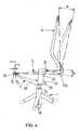
- Figur 4:
- den Bewegungsablauf des Stuhls zwischenVertikalposition undNeigungspositionals Prinzipdarstellung;
- Figur 5A:
- eine einzelne Armlehne;
- Figur 5B:
- einen Abschnitt der Stütze der Armlehne gemäss Figur 5A mit denRastkerben in Vergrösserung;
- Figur 5C:
- die Arretiermechanik an der Armlehne gemäss Figur 5A im Horizontalschnitt;
- Figur 6A:
- den aufgeschnittenen Rückenbezug mit einer eingesetzten Lumbal-Verstärkungseinlagein Perspektivansicht auf die Stuhlrückseite;
- Figur 6B:
- die Lumbal-Verstärkungseinlage aus Figur 6A; und
- Figur 6C:
- den Rückenbezug mit eingesetzter Lumbal-Verstärkungseinlage gemässFigur 6A in Seitenansicht als Teilschnitt.
- Figure 1A:
- an entire chair in side view;
- Figure 1B:
- the chair according to Figure 1A from below in perspective view;
- Figure 2A:
- a seat support with articulated back support and the tilt gas spring in side view as a partial section;
- Figure 2B:
- the articulated back support with the seat plate holder in perspective view;
- Figure 3A:
- the seat support from behind;
- Figure 3B:
- the seat support according to Figure 3A in side view as a partial section;
- Figure 3C:
- the seat support according to Figure 3A in plan view;
- Figure 4:
- the sequence of movements of the chair betweenvertical position andinclination position as a basic illustration;
- Figure 5A:
- a single armrest;
- Figure 5B:
- a portion of the support of the armrest according to Figure 5A with the notches in enlargement;
- Figure 5C:
- the locking mechanism on the armrest according to Figure 5A in horizontal section;
- Figure 6A:
- the cut back cover with an inserted lumbar reinforcement insert in perspective view of the back of the chair;
- Figure 6B:
- the lumbar reinforcement insert from FIG. 6A; and
- Figure 6C:
- the back cover with inserted lumbar reinforcement insert according to Figure 6A in side view as a partial section.
Der gesamte Stuhl gliedert sich in zwei Ebenen, das an sich bekannte UntergestellU unddenaufdas UntergestellU aufgesetzten SitzS, welcher die Erfindungenbeinhaltet und sich inein Sitzteil sowie ein Rückenteil gliedert. Das UntergestellU besteht aus einem typischen fünfarmigenStemfuss1 mit an den Enden der Arme10 angesetzten Rollen11, dieauf den Boden aufsetzen. Das Zentrum des Sternfusses1 wird von einem Hülsenstück12 gebildet, in welchem senkrecht eine Höhengasfeder13 eingesetztist. Aus der Höhengasfeder13 ragt auf der AchseA eine teleskopisch ausfahrbareKolbenstange14 heraus, auf die der Sitzträger2, welche das Basisteildes gesamten SitzesS darstellt, aufgesetzt ist. Der SitzS ist sowohl umdie AchseA drehbar als auch mit dem Aus- bzw. Einfahren der Kolbenstange14 auf der AchseA in der Höhe verstellbar. Zum SitzS gehören neben demSitzträger2, eine Sitzplatte3 mit aufgesetztem Sitzpolster34, ein Rückenträger4, eine Neigungsgasfeder5, auf deren Kolbenstange eine Schraubenfeder52 aufgeschoben ist, ein Rückenbezug6 und zwei Armlehnen7.The entire chair is divided into two levels, the per se known undercarriageU unddenaufdas baseU patch seatS, which includes inventions and is divided inein seat portion and a back portion. The base frameU consists of a typical five-armed star foot1 with
An der hinteren Basispartie20 des Sitzträgers2 ist die schräg aufsteigend angeordneteNeigungsgasfeder5 in der horizontalen DrehachseD1 angelenkt.Andererseits ist die Neigungsgasfeder5 am Querholm40 des Rückenträgers4in der horizontalen DrehachseD2 angelenkt. Aussen vom Querholm40 erstreckensich aufsteigend zwei Vertikalstützen41 und zwei praktisch nach vom- hin zur Vorderkante30 der Sitzplatte3 - rechtwinklig abgehende, horizontaleArme42. Zuvorderst sind die Arme42 schamierförmig mit dem Sitzträger2 verbunden,so dass hier die HauptdrehachseD gebildet wird, um die der Rückenträger4 als Ganzes schwenkbar ist. An die beiden Vertikalstützen41 setzt nachoben ein bügelförmiger Rückenspanner43 an, der vom Rückenbezug6 überzogenist.On the
Der im Prinzip vierarmige, massive Sitzträger2 weist die hintere Basispartie20mit der Bohrung200 auf, in welche die Kolbenstange14 der Höhengasfeder13eingesteckt ist. Von der Basispartie20 erstreckt sich nach beiden Seiten, horizontalund parallel zur HauptdrehachseD, je ein Querausleger21. An den Endensetzen sich die Querausleger21 mit einem nach oben abgewinkelten Ast22 fort, in den die unteren, freien Enden der Stützen71 der Armlehnen7 eingestecktsind und durch den sich die HauptdrehachseD mit dem angelenktenRückenträger4 erstreckt. Die Höhenlage der Armlehnen7 lässt sich mit einemseitlich am Ast22 zugänglichen Bedienknopf70 fixieren. Die Stützen71 erstreckensich vom Ast22 aufwärts zur horizontal angeordneten Armauflage72.Ebenfalls von der Basispartie20, zwischen beiden Querauslegern21, gehenzwei Tragarme23 ab, welche der Vorderkante30 der Sitzplatte3 zustreben.The massive four-
An der Unterseite der Sitzplatte3 sind zwei zueinander beabstandete Führungskulissen32 angeordnet, die auf die Vorderkante30 der Sitzplatte zulaufen.Vorn, nahe der Vorderkante30, schliessen die Führungskulissen32 miteiner Stirnbegrenzung320 ab. In die Führungskulissen32 greifen die freienEnden der Tragarme23, an denen sich Lagerzapfen230 befinden, ein. Auchan der Unterseite der Sitzplatte3 sind die vom Benutzer im Sitzen mit seinenHänden gut erreichbare Bedienhebel130,50 für die Betätigung der Höhengasfeder13 und der Neigungsgasfeder5 angebracht. Schliesslich ragen aus derUnterseite der Sitzplatte3, nahe deren Hinterkante31, zwei zueinander beabstandete,lösbare Befestigungselemente33 - z.B. Schrauben - heraus. Mittelsdieser Befestigungselemente33 lässt sich die auf zwei Scharnierplatten8 aufliegendeSitzplatte3 in einstellbarem Abstand zum Querholm40 des Rückenträgers4 fixieren. Bei geringerem Abstand fahren die Lagerzapfen230 derTragarme23 weiter in die Führungskulissen32 hinein, d.h. in Richtung derenBegrenzung320. Damit kann die Sitztiefe an die individuellen Benutzerbedürfnisseanpassen. Die Fluchtlinie beider Lagerzapfen230 ergibt die horizontaleGleitachseG. Die Scharnierplatten8 sind, wie die Neigungsgasfeder5, amQuerholm40 angelenkt.On the underside of the
In der gezeigten Darstellung ist die Sitzplatte3 maximal in Richtung desRückenträgers4 fixiert. Die Lagerzapfen230 des Sitzträgers2 befinden sicham weitesten vorn, unmittelbar vor den Stirnbegrenzungen320 der Führungskulissen32, während die Befestigungselemente33 in den Langlöchern80 derScharnierplatten8 am hinteren Anschlag stehen. Die Scharnierplatten8 sindzusammen mit der Neigungsgasfeder5 auf der horizontalen DrehachseD2schwenkbar befestigt. Die DrehachseD2 wird durch einen längs des Querholms40 feststehend befestigten Achsstab81 gebildet, wobei zwischen denbeiden Scharnierplatten8 die Neigungsgasfeder5 angeordnet ist und dieDrehachseD2 parallel zu HauptdrehachseD liegt. Der Achsstab81 ist partiellin den Querholm40 eingebettet. Ein Befestigungselement33 besteht vorzugsweiseaus einem aus der Unterseite der Sitzplatte3 herausragenden Gewindebolzen330 und einer von unten gegen die Schamierplatte8 aufschraubbarenMutter331. Der Gewindebolzen330 steckt fest in der Sitzplatte3 unddurchragt einen Längsschlitz80 in der Schamierplatte8, so dass diese überdie Ausdehnung des Längsschlitzes80 verschiebbar fixiert werden kann unddamit die Position der GleitachseG festgelegt wird. Zur Betätigung der HöhenundNeigungsgasfeder13,5 verlaufen von den Bedienhebeln130,50 Bowdenzüge131,51. Die Ventilstange zur Auslösung der Neigungsgasfeder5 ist derBasispartie20 des Sitzträgers2 zugewandt. In die Basispartie20 ist eine Kugelpfanne201 eingesetzt, in der eine Lagerkugel202 als Abstützung für dieNeigungsgasfeder5 auf der Drehachse D1, liegt. Durch die Lagerkugel202erstreckt sich ein Fortsatz der Ventilstange der Neigungsgasfeder5. An diesemFortsatz steht ein Schaltelement, welches über einen Bowdenzug mit demzugehörigen Bedienhebel50 verbunden ist. Bei Betätigung des Bedienhebels50 bewegt das Schaltelement die Ventilstange der Neigungsgasfeder5, diesomit in Offenstellung kommt. Wird kein Körperdruck auf den Rückenträger4ausgeübt, fährt die Kolbenstange aus und der Rückenträger4 richtet sich biszurVertikalposition auf. Wird Körperdruck auf den Rückenträger4 ausgeübt -die Neigungsgasfeder5 befindet sich nicht bereits in maximal eingefahrenemZustand -, so lässt sich der Rückenträger4 in seine maximaleNeigungspositiondrücken.In the illustration shown, the
Im Ast22 befindet sich eine von oben zugängliche Einstecköffnung220 für dieAufnahme der unteren Kerbenpartie710 (s. Figuren 5A und 5B) der Stütze71der einsteckbaren, höhenverstellbaren Armlehne7. Der Bedienknopf70 für dieHöhenarretierung der Armlehne7 liegt an der Aussenwandung des Astes22und ist tangential an der Einstecköffnung220 vorbei ausgerichtet. Die Gelenkverbindungauf der HauptdrehachseD zwischen dem Ast22 und dem zulaufendenArm42 wird durch jeweils eine Aussparung221,421 halber Materialstärkegebildet, so dass die entstandenen, vorn abgerundeten Zapfen222,422in die jeweils gegenüber liegende Aussparung421,221 eingreifen. Durch dieaneinander liegenden Zapfen222,422 erstreckt sich auf der HauptdrehachseD ein fest sitzender Achsstift423. Der Rückenbezug6 ist über die Länge desAchsstabes81 bis an die Hinterseite des Querholms40 gezogen und mittelsdurch den Achsstift423 gehende Befestigungselemente424 - z.B. Schrauben- dort fixiert. Im Eckbereich, wo der Querholm40, die Vertikalstütze41 und derArm42 zusammen kommen, weist der Rückenbezug6 eine Aussparung60auf.In
Erkennbar sind in der Basispartie20 die Bohrung200 zur Aufnahme der Kolbenstange14 der Höhengasfeder13, neben der Bohrung200 die Führungen203 für die Bowdenzüge51,131 und weiter hinten die Kugelpfanne201 zurAufnahme der Auslösekugel202 für die Neigungsgasfeder5 und neben derKugelpfanne201 eine Aussparung204 für den ankommenden Bowdenzug51.Am Ast22 sieht man die hinein gehende Einstecköffnung220, den Bedienknopf70 und die auf der Hauptdrehachse D gelegenen Zapfen222 und diejeweils zugehörigen Aussparungen221. Die Tragarme23 zeigen vorn die nachder Seite herausstehenden Lagerzapfen230.In the
Betrachtet wird das Verhalten von Rückenträger4 und Sitzplatte3 beim rückwärtigenNeigen des Rückenträgers4. Die Sitzplatte3 ist mittels der Befestigungselemente33 in einer definierten Position fixiert. InVertikalposition des Rückenträgers4 liegt die GleitachseG innerhalb der Führungskulissen32 aufder PositionP0, d.h. von den Stirnbegrenzungen320 relativ entfernt und dieSitzplatte3 hat ihre Normallage.The behavior of the
Wird der Rückenträger4 nun um den maximal möglichen Steltwinkel α um dieHauptdrehachseD nach hinten in dieNeigungsposition bewegt, so verkürztsich die Distanz zwischen der DrehachseD2 und der ursprünglichen PositionP0. Da die Sitzplatte3 quer verschiebbar zur HauptdrehachseD mit den Führungskulissen32 auf den Lagerzapfen230 der Tragarme23 des Sitzträgers2hängt, wird die Sitzplatte3 in Richtung der Vorderkante30 geschoben. DieGleitachseG verlagert sich um die Wegstreckes auf die PositionP1. Zugleichsenkt sich die Sitzplatte3 an der Hinterkante31 deutlich ab, während an derVorderkante30 ein proportionales, relativ geringes Anheben geschieht. Somitbesteht ein synchroner Bewegungsablauf zwischen Rückenträger4 und Sitzplatte3.If the
Die Armlehne7 besitzt die etwa senkrechte Stütze71, an der oben die etwahorizontale Armauflage72 befestigt ist. Unten hat die im Prinzip elliptische Stütze71 eine Kerbenpartie710, mit einem systematischen Kerbenraster, bestehendaus gleichmässig beanstandeten halbrunden Kerben711, die übereinandernach der Geometrielehre auf einem Hauptscheitel liegen. Die Rundungender Kerben711 weisen auf die MittelachseM der Stütze71 hin. im aufsteigendenAst22 des Sitzträgers2 ist eine tangential an der Einstecköffnung220vorbei ausgerichtete Bohrung73 vorgesehen, die intern eine Verengung730aufweist. Von der einen Bohrungsseite ist ein als Druckknopf ausgebildeter, federbelasteterBedienknopf70 eingesetzt; von der anderen Seite ein Tellerelement74, dessen durchmesserverminderter Schaft740 durch die Verengung730 ragt und fest mit dem Bedienknopf70 verbunden ist. Eine Schraubenfeder75 ist bestrebt, den Bedienknopf70 nach aussen zu drücken und zieht dabeidas Tellerelement74 in die Bohrung73 hinein. Hierbei greift ein Kreissegment741 des Tellerelements74 in die auf das Niveau des Bedienknopfs70 gestellte Kerbe711 ein. Die Armlehne7 ist damit in der ausgezogenen Höhe fixiert. ZumLösen muss man den Bedienknopf70 gegen die Wirkung der Schraubenfeder75 eindrücken, so dass Tellerelement74 und die anstehende Kerbe711 ausserEingriff kommen. Nun lässt sich die Armlehne7 in ihrer Höhe verstellen bis einemit der gewünschten Höhe korrespondierende Kerbe711 vom Tellerelement74belegt wird.The
Der Rückenbezug6 weist im Lumbalbereich eine interne, nach oben offeneTasche61 auf, in die eine plattenförmige Lumbal-Verstärkungseinlage9 eingestecktist. Die Verstärkungseinlage9 besitzt querverlaufende Elastizitätsschlitze90 sowie eine nach oben ragende Fixierzunge91. Diese Fixierzunge91ragt durch einen Schlitz62 im Rückenbezug6 auf der Hinterseite des Stuhls,wobei der Schlitz62 oberhalb der Tasche61 liegt. Auf der Vorderseite, hin zumBenutzer hat der Rückenbezug eine Polsterung63.The
Will man die Höhenlage der Verstärkungseinlage9 verstellen, wird die Fixierzunge91 vom Rückenbezug6 gelöst und die Verstärkungseinlage9 weiter indie Tasche61 eingeschoben oder herausgezogen. Zum Festlegen der Fixierzunge91 in der gewählten Höhe bietet sich an, deren Rückseite mit einer erstenSchicht910 eines Klettverschlusses zu versehen und die komplementärezweite Schicht911 des Klettverschlusses am Rückenbezug6, gegenüber derersten Schicht910 aufzubringen. Die unteren Enden des Rückenbezugs6 sindauf der Hinterseite des Querholms40 festgelegt.If you want to adjust the height of the reinforcing
Claims (12)
- Chair with an adjustment mechanism having:a) an underframe (U) with a foot (1) which is placed onto the ground and witha pneumatic spring (13) which is inserted in the underframe (U) on a verticalaxis (A) and has a telescopically extendable piston rod (14) for settingthe height of the chair;b) a seat (S) with:ba) a seat part comprising a seat support (2) which is arranged right at thebottom and is placed onto the piston rod (14), and a seat plate (3) which issupported by the seat support (2); andbb) a pivotable back part comprising a back support (4) which is hinged on amain rotational axis (D) which runs transversely above the seat plate (3),parallel to its front edge (30); andc) an inclination spring (5) which is hinged at one end to the seat support (2)on a rotational axis (D1) and at the other end to the back support (4) on arotational axis (D2),characterised in thatd) on its lower side the seat plate (3) has guide cranks (32) in which supportingarms (23) of the seat support (2) engage in a manner such that theycan be displaced transverse to the main rotational axis (D); ande) the seat plate (3) is hinged to the back support (4) on the rotational axis(D2).
- Chair with an adjustment mechanism as claimed in claim 1,characterised in that in the main rotational axis (D) there are connected to oneanother in an articulated manner:a) two arms (42) of the back support (4), which arms (42) extend laterallyabove the seat plate (3); andb) in principle, two vertical branches (22) as angled extensions of transverseextension arms (21), running below the seat plate (3), of the seat support(2),c) the branches (22) each having a plug-in opening (220) for receiving anarmrest.
- Chair with an adjustment mechanism as claimed in claim 1 or 2,characterised in thata) the back support (4) has a transverse strut (40) which extends between thearms (42), parallel to the main rotational axis (D);b) the back support (4) has two stays (41) which extend upward from theintersection of the transverse strut (40) with the respective arm (42);c) fastened to the transverse strut (40) is an axial bar (81) through which runsthe rotational axis (D2) with the hinged seat plate (3) and the hinged inclinationspring (5), preferably a pneumatic spring with an attached helicalspring (52); andd) a back cover (6) is stretched between the arms (42).
- Chair with an adjustment mechanism as claimed in claim 3,characterised in thata) a respective hinge plate (8) is hinged to the axial bar (81) on both sides ofthe hinged inclination spring (5); andb) the seat plate (3) is fastened on the hinge plates (8) at a selectable distancefrom the rotational axis (D2).
- Chair with an adjustment mechanism as claimed in claim 3,characterised in thata) a ball socket (201) for holding a bearing ball (202) is provided in the seatsupport (2);b) the bearing ball (202) serves as a support for the pneumatic inclinationspring (5) on the rotational axis (D1);c) a continuation of the valve rod of the pneumatic inclination spring (5) extendsthrough the bearing ball (202); andd) on the continuation is a control element which is connected to an associatedoperating lever (50), so that the locking of the pneumatic inclinationspring (5) can be cancelled.
- Chair with an adjustment mechanism as claimed in claim 1,characterised in thata) two spaced apart guide cranks (32) are provided in the vicinity of the frontedge (30) of the seat plate (3);b) the guide cranks (32) have an end limitation (320) at the front; andc) bearing pegs (230) which are arranged right at the front of the free ends ofthe supporting arms (23) engage in the guide cranks (32).
- Chair with an adjustment mechanism as claimed in claim 1, 2 or 3,characterised in that a back cover (6) for pulling onto the back support (4) isprovided and a lumbar reinforcing insert (9) which is height-displaceable andcan be fixed at the height selected is arranged in the back cover (6).
- Chair with an adjustment mechanism as claimed in claim 7,characterised in thata) the lumbar reinforcing insert (9) consists of a flexible plate and an upwardlyprotruding fixing tongue (91);b) an upwardly open pocket (61) into which the lumbar reinforcing insert (9) isinserted is provided in the back cover (6);c) the fixing tongue (91) protrudes out of the back cover (6) through a slot (62)and can be fastened releasably to the back cover (6), as a result of whichthe selected height position of the lumbar reinforcing insert (9) is retained.
- Chair with an adjustment mechanism as claimed in claim 7 or 8,characterised in that at its lower edge the back cover (6) is fixed on the rearside of the transverse strut (40) by means of fastening elements (424) whichreach through the transverse strut (40) and at the same time hold the axial bar(81) on the transverse strut (40).
- Chair with an adjustment mechanism as claimed in claim 1 or 5,characterised in that armrests (7) for attaching to the seat support (2) are provided;a) each armrest (7) has an approximately vertical stay (71) with an arm support (72) arranged at the top;b) a notched section (710) having a systematic grid of notches, consisting ofsemicircular notches (711) lying one above another, is provided on the stay(71);c) the notched section (710) is plugged into the plug-in opening (220) in theraised branch (22) of the seat support (2);d) in the branch (22) within a hole (73) which the inserted notched section(710) partially touches, there is seated an operating button (70) which isstressed by a spring (75) and engages in a locking manner in the contourof a notch (711) standing in a position with respect to the operating button(70).
- Chair with an adjustment mechanism as claimed in claim 10,characterised in thata) the cross section of the stay (71) has an elliptical shape;b) the notches (711) lie on a main apex of the ellipse; andc) the operating button (70) is connected axially to a disk element (74) ofwhich a circular segment (741) engages in the positioned notch (711).
- Chair with an adjustment mechanism as claimed in claim 11,characterised in that the operating button (70) and the disk element (74) areconnected to each other by a passage, of reduced diameter, of the hole (73),as a result of which the operating button (70) is situated at one end of the hole(73) and the spring (75) is supported, while at the other end of the hole (73) thedisk element (74) is supported.
Applications Claiming Priority (1)
| Application Number | Priority Date | Filing Date | Title |
|---|---|---|---|
| PCT/IB1998/001671WO2000022960A1 (en) | 1998-10-21 | 1998-10-21 | Adjustment mechanism, back cover and arm rest for a chair |
Publications (2)
| Publication Number | Publication Date |
|---|---|
| EP1039815A1 EP1039815A1 (en) | 2000-10-04 |
| EP1039815B1true EP1039815B1 (en) | 2003-09-17 |
Family
ID=11004764
Family Applications (1)
| Application Number | Title | Priority Date | Filing Date |
|---|---|---|---|
| EP98946677AExpired - LifetimeEP1039815B1 (en) | 1998-10-21 | 1998-10-21 | Chair with adjustment mechanism |
Country Status (6)
| Country | Link |
|---|---|
| US (1) | US6557939B1 (en) |
| EP (1) | EP1039815B1 (en) |
| JP (1) | JP2002527175A (en) |
| AT (1) | ATE249772T1 (en) |
| DE (1) | DE59809667D1 (en) |
| WO (1) | WO2000022960A1 (en) |
Cited By (3)
| Publication number | Priority date | Publication date | Assignee | Title |
|---|---|---|---|---|
| WO2005120291A1 (en) | 2004-06-14 | 2005-12-22 | Vitra Patente Ag | Seat comprising a synchronous mechanism |
| DE202010008894U1 (en) | 2010-10-26 | 2010-12-30 | Vitra Patente Ag | Height-adjustable lumbar support for a chair |
| WO2016044957A1 (en) | 2014-09-26 | 2016-03-31 | Vitra Patente Ag | Chair having a deflection that is mutually synchronous between backrest and a seat |
Families Citing this family (25)
| Publication number | Priority date | Publication date | Assignee | Title |
|---|---|---|---|---|
| AU783829B2 (en) | 2000-09-28 | 2005-12-08 | Formway Furniture Limited | A reclinable chair |
| NZ518944A (en) | 2002-05-14 | 2004-09-24 | Formway Furniture Ltd | Height adjustable arm for chair with outer stem releasably lockable to inner stem by engagement of recesses |
| US6869142B2 (en) | 2002-09-12 | 2005-03-22 | Steelcase Development Corporation | Seating unit having motion control |
| USD499564S1 (en) | 2002-10-22 | 2004-12-14 | Vitra Patente Ag | Chair |
| USD509969S1 (en) | 2003-09-05 | 2005-09-27 | Steelcase Development Corporation | Seating unit |
| US7188900B1 (en)* | 2003-11-17 | 2007-03-13 | Hni Technologies Inc. | Flexible support for a chair backrest |
| US20050189807A1 (en)* | 2004-02-27 | 2005-09-01 | Norman Christopher J. | Chair with functional armrest |
| USD536890S1 (en) | 2004-03-03 | 2007-02-20 | Steelcase Development Corporation | Seating unit |
| ES1057119Y (en)* | 2004-03-24 | 2004-10-01 | Metalseat Srl | ADJUSTABLE OFFICE ARMCHAIR STRUCTURE WITH ARTICULATION FOR THE SYNCHRONIC MOVEMENT OF THE SEAT AND BACK. |
| USD544722S1 (en) | 2004-06-07 | 2007-06-19 | Steelcase Development Corporation | Chair |
| HK1064859A2 (en)* | 2004-06-21 | 2005-01-14 | 田雨阳 | Synchronous coordinate system of back of chair |
| JP4652761B2 (en)* | 2004-09-22 | 2011-03-16 | 株式会社岡村製作所 | Reclining chair |
| USD550975S1 (en) | 2005-10-05 | 2007-09-18 | Vitra Patente Ag | Chair |
| US20080252124A1 (en)* | 2007-04-13 | 2008-10-16 | Chen Yung-Hua | Apparatus for adjusting the angle of a seat back of an office chair |
| JP2010227314A (en)* | 2009-03-27 | 2010-10-14 | Oki Electric Ind Co Ltd | Chair |
| US8596719B2 (en) | 2010-10-01 | 2013-12-03 | Permobil Ab | Wheelchair backrest assembly |
| EP2630894A4 (en)* | 2010-10-19 | 2014-11-12 | Okamura Corp | Chair with armrest |
| USD721529S1 (en) | 2013-06-07 | 2015-01-27 | Steelcase Inc. | Handle apparatus |
| US20150173515A1 (en)* | 2013-12-23 | 2015-06-25 | Freedman Seats Ltd | Seat |
| GB2538056B (en)* | 2015-04-28 | 2017-11-29 | Gordon Vickers Adam | Adjustable chair |
| IT201800006788A1 (en)* | 2018-06-28 | 2019-12-28 | CHAIR STRUCTURE | |
| CN113507865A (en) | 2019-02-21 | 2021-10-15 | 斯特尔凯斯公司 | Body support assembly and methods for use and assembly thereof |
| US11357329B2 (en) | 2019-12-13 | 2022-06-14 | Steelcase Inc. | Body support assembly and methods for the use and assembly thereof |
| TWI723913B (en) | 2020-07-08 | 2021-04-01 | 廣力達企業有限公司 | Height adjustment structure |
| USD1063474S1 (en) | 2022-09-07 | 2025-02-25 | Steelcase Inc. | Chair |
Family Cites Families (13)
| Publication number | Priority date | Publication date | Assignee | Title |
|---|---|---|---|---|
| CH568738A5 (en) | 1973-08-20 | 1975-11-14 | Fehlbaum Fa | |
| CH582498A5 (en) | 1974-09-06 | 1976-12-15 | Fehlbaum Fa | |
| NL8103037A (en)* | 1981-06-23 | 1983-01-17 | Gispen & Staalmeubel Bv | CHAIR. |
| DE8326792U1 (en)* | 1983-09-17 | 1984-01-05 | Fromme, Heinrich, 4815 Schloß Holte-Stukenbrock | CHAIR, ESPECIALLY SWIVEL CHAIR |
| DE8511034U1 (en)* | 1985-04-16 | 1985-06-05 | Steifensand Sitzmöbel- und Tischfabrik Inh.: F. Martin Steifensand, 8501 Wendelstein | Seating furniture in the form of a chair or armchair, in particular for office purposes |
| DE3617539C1 (en)* | 1986-05-24 | 1987-07-23 | Grammer Sitzsysteme Gmbh | Seat with adjustable seat plate and reclining backrest |
| DE8616836U1 (en) | 1986-06-24 | 1987-10-22 | Hartmann, Günter, 5800 Hagen | Seating furniture, especially chairs |
| AU2066795A (en) | 1994-03-17 | 1995-10-03 | Froscher Gmbh & Co. Kg | Chair or seat |
| AT402602B (en) | 1995-02-28 | 1997-07-25 | Eckhard Hansen Dipl Ing | CHAIR CHAIR |
| US5725276A (en)* | 1995-06-07 | 1998-03-10 | Ginat; Jonathan | Tilt back chair and control |
| US5899530A (en)* | 1995-08-23 | 1999-05-04 | Global Upholstery Company | Control mechanism for a chair |
| EP0815778B1 (en) | 1996-06-28 | 1998-02-04 | Steelcase Strafor (S.A.) | Improvements for systems with differential shaping of back supports of office chairs |
| US6149236A (en) | 1996-10-14 | 2000-11-21 | Vitra Patents Ag | Chair frame, control mechanism and upholstery |
- 1998
- 1998-10-21EPEP98946677Apatent/EP1039815B1/ennot_activeExpired - Lifetime
- 1998-10-21JPJP2000576743Apatent/JP2002527175A/enactivePending
- 1998-10-21WOPCT/IB1998/001671patent/WO2000022960A1/enactiveIP Right Grant
- 1998-10-21DEDE59809667Tpatent/DE59809667D1/ennot_activeExpired - Lifetime
- 1998-10-21ATAT98946677Tpatent/ATE249772T1/ennot_activeIP Right Cessation
- 1998-10-21USUS09/581,889patent/US6557939B1/ennot_activeExpired - Lifetime
Cited By (3)
| Publication number | Priority date | Publication date | Assignee | Title |
|---|---|---|---|---|
| WO2005120291A1 (en) | 2004-06-14 | 2005-12-22 | Vitra Patente Ag | Seat comprising a synchronous mechanism |
| DE202010008894U1 (en) | 2010-10-26 | 2010-12-30 | Vitra Patente Ag | Height-adjustable lumbar support for a chair |
| WO2016044957A1 (en) | 2014-09-26 | 2016-03-31 | Vitra Patente Ag | Chair having a deflection that is mutually synchronous between backrest and a seat |
Also Published As
| Publication number | Publication date |
|---|---|
| JP2002527175A (en) | 2002-08-27 |
| ATE249772T1 (en) | 2003-10-15 |
| US6557939B1 (en) | 2003-05-06 |
| DE59809667D1 (en) | 2003-10-23 |
| EP1039815A1 (en) | 2000-10-04 |
| WO2000022960A1 (en) | 2000-04-27 |
Similar Documents
| Publication | Publication Date | Title |
|---|---|---|
| EP1039815B1 (en) | Chair with adjustment mechanism | |
| EP1039816B1 (en) | Chair mechanism | |
| EP0949875B1 (en) | Chair frame, control mechanism and upholstery | |
| DE3930983C2 (en) | Seating with an adjustable seat | |
| DE60215709T2 (en) | office chair | |
| DE2600274B2 (en) | Chair with adjustable backrest | |
| EP0970637A1 (en) | Working chair with adjustable seat-depth | |
| DE4327373A1 (en) | Office chair | |
| DE3521488A1 (en) | WORK CHAIR | |
| DE2820063A1 (en) | CHAIR | |
| DE1294618B (en) | Adjustable rocking chair | |
| EP3528664B1 (en) | Synchronous chair mechanism and chair with such | |
| EP0263323B1 (en) | Sitting furniture | |
| DE202011000125U1 (en) | birthing stool | |
| DE10026531C2 (en) | chair | |
| DE8660017U1 (en) | Tilt device for seating furniture | |
| EP4464197A1 (en) | Chair and furniture composition | |
| DE3800751A1 (en) | Armchair | |
| DE68918921T2 (en) | Improvements in chairs. | |
| DE29901666U1 (en) | Armrest, especially for office and swivel chairs | |
| EP3248508B1 (en) | Seating device | |
| EP1118294A2 (en) | seating furniture | |
| DE10126204A1 (en) | Adjustable support system in seat with swiveling back rest comprises cushion for lumbar region mounted in back rest which is attached at top to pivot | |
| AT411006B (en) | SEAT DEVICE FOR LAYING ON SEAT FURNITURE | |
| DE102005018194B4 (en) | Seating and / or reclining furniture, in particular upholstered seating |
Legal Events
| Date | Code | Title | Description |
|---|---|---|---|
| PUAI | Public reference made under article 153(3) epc to a published international application that has entered the european phase | Free format text:ORIGINAL CODE: 0009012 | |
| 17P | Request for examination filed | Effective date:20000617 | |
| AK | Designated contracting states | Kind code of ref document:A1 Designated state(s):AT BE CH DE DK ES FR GB GR IT LI NL | |
| 17Q | First examination report despatched | Effective date:20020802 | |
| GRAH | Despatch of communication of intention to grant a patent | Free format text:ORIGINAL CODE: EPIDOS IGRA | |
| RTI1 | Title (correction) | Free format text:CHAIR WITH ADJUSTMENT MECHANISM | |
| GRAH | Despatch of communication of intention to grant a patent | Free format text:ORIGINAL CODE: EPIDOS IGRA | |
| GRAA | (expected) grant | Free format text:ORIGINAL CODE: 0009210 | |
| AK | Designated contracting states | Kind code of ref document:B1 Designated state(s):AT BE CH DE DK ES FR GB GR IT LI NL | |
| PG25 | Lapsed in a contracting state [announced via postgrant information from national office to epo] | Ref country code:NL Free format text:LAPSE BECAUSE OF FAILURE TO SUBMIT A TRANSLATION OF THE DESCRIPTION OR TO PAY THE FEE WITHIN THE PRESCRIBED TIME-LIMIT Effective date:20030917 Ref country code:IT Free format text:LAPSE BECAUSE OF FAILURE TO SUBMIT A TRANSLATION OF THE DESCRIPTION OR TO PAY THE FEE WITHIN THE PRE;WARNING: LAPSES OF ITALIAN PATENTS WITH EFFECTIVE DATE BEFORE 2007 MAY HAVE OCCURRED AT ANY TIME BEFORE 2007. THE CORRECT EFFECTIVE DATE MAY BE DIFFERENT FROM THE ONE RECORDED.SCRIBED TIME-LIMIT Effective date:20030917 Ref country code:GB Free format text:LAPSE BECAUSE OF FAILURE TO SUBMIT A TRANSLATION OF THE DESCRIPTION OR TO PAY THE FEE WITHIN THE PRESCRIBED TIME-LIMIT Effective date:20030917 Ref country code:FR Free format text:LAPSE BECAUSE OF FAILURE TO SUBMIT A TRANSLATION OF THE DESCRIPTION OR TO PAY THE FEE WITHIN THE PRESCRIBED TIME-LIMIT Effective date:20030917 | |
| REG | Reference to a national code | Ref country code:GB Ref legal event code:FG4D Free format text:NOT ENGLISH | |
| REG | Reference to a national code | Ref country code:CH Ref legal event code:EP | |
| REG | Reference to a national code | Ref country code:CH Ref legal event code:NV Representative=s name:DR. GERHARD ULLRICH C/O AXON PATENT GMBH | |
| PG25 | Lapsed in a contracting state [announced via postgrant information from national office to epo] | Ref country code:AT Free format text:LAPSE BECAUSE OF NON-PAYMENT OF DUE FEES Effective date:20031021 | |
| REF | Corresponds to: | Ref document number:59809667 Country of ref document:DE Date of ref document:20031023 Kind code of ref document:P | |
| PG25 | Lapsed in a contracting state [announced via postgrant information from national office to epo] | Ref country code:BE Free format text:LAPSE BECAUSE OF NON-PAYMENT OF DUE FEES Effective date:20031031 | |
| PG25 | Lapsed in a contracting state [announced via postgrant information from national office to epo] | Ref country code:GR Free format text:LAPSE BECAUSE OF FAILURE TO SUBMIT A TRANSLATION OF THE DESCRIPTION OR TO PAY THE FEE WITHIN THE PRESCRIBED TIME-LIMIT Effective date:20031217 Ref country code:DK Free format text:LAPSE BECAUSE OF FAILURE TO SUBMIT A TRANSLATION OF THE DESCRIPTION OR TO PAY THE FEE WITHIN THE PRESCRIBED TIME-LIMIT Effective date:20031217 | |
| PG25 | Lapsed in a contracting state [announced via postgrant information from national office to epo] | Ref country code:ES Free format text:LAPSE BECAUSE OF FAILURE TO SUBMIT A TRANSLATION OF THE DESCRIPTION OR TO PAY THE FEE WITHIN THE PRESCRIBED TIME-LIMIT Effective date:20031228 | |
| NLV1 | Nl: lapsed or annulled due to failure to fulfill the requirements of art. 29p and 29m of the patents act | ||
| GBV | Gb: ep patent (uk) treated as always having been void in accordance with gb section 77(7)/1977 [no translation filed] | Effective date:20030917 | |
| BERE | Be: lapsed | Owner name:*VITRA PATENTE A.G. Effective date:20031031 | |
| PLBE | No opposition filed within time limit | Free format text:ORIGINAL CODE: 0009261 | |
| STAA | Information on the status of an ep patent application or granted ep patent | Free format text:STATUS: NO OPPOSITION FILED WITHIN TIME LIMIT | |
| 26N | No opposition filed | Effective date:20040618 | |
| EN | Fr: translation not filed | ||
| PGFP | Annual fee paid to national office [announced via postgrant information from national office to epo] | Ref country code:CH Payment date:20041025 Year of fee payment:7 | |
| PG25 | Lapsed in a contracting state [announced via postgrant information from national office to epo] | Ref country code:LI Free format text:LAPSE BECAUSE OF NON-PAYMENT OF DUE FEES Effective date:20051031 Ref country code:CH Free format text:LAPSE BECAUSE OF NON-PAYMENT OF DUE FEES Effective date:20051031 | |
| REG | Reference to a national code | Ref country code:CH Ref legal event code:PL | |
| PGFP | Annual fee paid to national office [announced via postgrant information from national office to epo] | Ref country code:DE Payment date:20101223 Year of fee payment:13 | |
| PG25 | Lapsed in a contracting state [announced via postgrant information from national office to epo] | Ref country code:DE Free format text:LAPSE BECAUSE OF NON-PAYMENT OF DUE FEES Effective date:20120501 | |
| REG | Reference to a national code | Ref country code:DE Ref legal event code:R119 Ref document number:59809667 Country of ref document:DE Effective date:20120501 |