EP1039620A2 - Energy conversion apparatus - Google Patents
Energy conversion apparatusDownload PDFInfo
- Publication number
- EP1039620A2 EP1039620A2EP00105615AEP00105615AEP1039620A2EP 1039620 A2EP1039620 A2EP 1039620A2EP 00105615 AEP00105615 AEP 00105615AEP 00105615 AEP00105615 AEP 00105615AEP 1039620 A2EP1039620 A2EP 1039620A2
- Authority
- EP
- European Patent Office
- Prior art keywords
- power
- converters
- conversion apparatus
- energy conversion
- energy
- Prior art date
- Legal status (The legal status is an assumption and is not a legal conclusion. Google has not performed a legal analysis and makes no representation as to the accuracy of the status listed.)
- Withdrawn
Links
Images


Classifications
- H—ELECTRICITY
- H02—GENERATION; CONVERSION OR DISTRIBUTION OF ELECTRIC POWER
- H02J—CIRCUIT ARRANGEMENTS OR SYSTEMS FOR SUPPLYING OR DISTRIBUTING ELECTRIC POWER; SYSTEMS FOR STORING ELECTRIC ENERGY
- H02J1/00—Circuit arrangements for DC mains or DC distribution networks
- H02J1/10—Parallel operation of DC sources
- H02J1/102—Parallel operation of DC sources being switching converters
- H—ELECTRICITY
- H02—GENERATION; CONVERSION OR DISTRIBUTION OF ELECTRIC POWER
- H02J—CIRCUIT ARRANGEMENTS OR SYSTEMS FOR SUPPLYING OR DISTRIBUTING ELECTRIC POWER; SYSTEMS FOR STORING ELECTRIC ENERGY
- H02J3/00—Circuit arrangements for AC mains or AC distribution networks
- H02J3/38—Arrangements for parallely feeding a single network by two or more generators, converters or transformers
- H02J3/381—Dispersed generators
- H—ELECTRICITY
- H02—GENERATION; CONVERSION OR DISTRIBUTION OF ELECTRIC POWER
- H02J—CIRCUIT ARRANGEMENTS OR SYSTEMS FOR SUPPLYING OR DISTRIBUTING ELECTRIC POWER; SYSTEMS FOR STORING ELECTRIC ENERGY
- H02J3/00—Circuit arrangements for AC mains or AC distribution networks
- H02J3/38—Arrangements for parallely feeding a single network by two or more generators, converters or transformers
- H02J3/46—Controlling of the sharing of output between the generators, converters, or transformers
- H—ELECTRICITY
- H02—GENERATION; CONVERSION OR DISTRIBUTION OF ELECTRIC POWER
- H02J—CIRCUIT ARRANGEMENTS OR SYSTEMS FOR SUPPLYING OR DISTRIBUTING ELECTRIC POWER; SYSTEMS FOR STORING ELECTRIC ENERGY
- H02J2300/00—Systems for supplying or distributing electric power characterised by decentralized, dispersed, or local generation
- H02J2300/20—The dispersed energy generation being of renewable origin
- H02J2300/22—The renewable source being solar energy
- H02J2300/24—The renewable source being solar energy of photovoltaic origin
- H02J2300/26—The renewable source being solar energy of photovoltaic origin involving maximum power point tracking control for photovoltaic sources
- H—ELECTRICITY
- H02—GENERATION; CONVERSION OR DISTRIBUTION OF ELECTRIC POWER
- H02J—CIRCUIT ARRANGEMENTS OR SYSTEMS FOR SUPPLYING OR DISTRIBUTING ELECTRIC POWER; SYSTEMS FOR STORING ELECTRIC ENERGY
- H02J2300/00—Systems for supplying or distributing electric power characterised by decentralized, dispersed, or local generation
- H02J2300/20—The dispersed energy generation being of renewable origin
- H02J2300/28—The renewable source being wind energy
- Y—GENERAL TAGGING OF NEW TECHNOLOGICAL DEVELOPMENTS; GENERAL TAGGING OF CROSS-SECTIONAL TECHNOLOGIES SPANNING OVER SEVERAL SECTIONS OF THE IPC; TECHNICAL SUBJECTS COVERED BY FORMER USPC CROSS-REFERENCE ART COLLECTIONS [XRACs] AND DIGESTS
- Y02—TECHNOLOGIES OR APPLICATIONS FOR MITIGATION OR ADAPTATION AGAINST CLIMATE CHANGE
- Y02E—REDUCTION OF GREENHOUSE GAS [GHG] EMISSIONS, RELATED TO ENERGY GENERATION, TRANSMISSION OR DISTRIBUTION
- Y02E10/00—Energy generation through renewable energy sources
- Y02E10/50—Photovoltaic [PV] energy
- Y02E10/56—Power conversion systems, e.g. maximum power point trackers
Definitions
- the present inventionrelates to an energy conversion apparatus wherein a DC power obtained by DC power supply apparatus such as a wind power generator or various battery apparatus or a photovoltaic array is input to an inverter via a DC-DC converter and converted to an AC power, and the AC power is supplied to a power system.
- the photovoltaic arrayis constructed according to the Japanese Industrial Standards (JIS).
- JISJapanese Industrial Standards
- the photovoltaic arrayhas a frame and/or a base, as well as other constituent elements.
- photovoltaic modules or photovoltaic panelsare mechanically integrated and interconnected as one unit.
- the photovoltaic arrayconstitutes one of DC power generators.
- the photovoltaic moduleis a minimum power generation unit wherein photovoltaic cells or photovoltaic sub-modules are connected in series and/or in parallel and encapsulated in a casing for protection against the environment, and the photovoltaic module has external terminals to provide a prescribed output.
- the photovoltaic panelis an assembly of photovoltaic modules which are mechanically coupled and interconnected, thereby to permit installation on the site.
- a DC power obtained from a plurality of soler battery arraysis converted to an AC current by means of a single power conditioner and reversely supplied to a power system.
- the power conditioner used in this caseserves to enhance the characteristics of all photovoltaic arrays.
- the power conditionerhas a function (maximum power point tracking (MPPT) control function) for analyzing an operation point (average value) at which the total power generated by all photovoltaic arrays takes a maximum value and thus tracking a maximum power point.
- MPPTmaximum power point tracking
- FIG. 1shows an example of a hip roof.
- Photovoltaic arrays (PVE) 11, (PVW) 12, (PVS) 13 and (PVN) 14, which provide array outputs of 500 W, 500 W, 1 kW and 1 kW, respectively,are disposed on the east, west, south and north sides.
- the modules constituting the photovoltaic arrays 11 to 14have different temperatures due to a difference in intensity of solar radiation.
- a DC-DC convertertracks and controls a maximum point of generated power.
- DC currents from the photovoltaic arrays 11 to 14, as shown in FIG. 3are input to a DC-DC converter 2 having a maximum power tracking function. A point at which the generated power takes a maximum value is found, and the photovoltaic arrays 11 to 14 are operated at this point.
- An output from the DC-DC converter 2is delivered to an inverter 5.
- the inverter 5performs DC/AC conversion and produces an AC power.
- a single DC-DC convertertracks and controls the maximum point of the generated power of all photovoltaic arrays 11 to 14. As a result, the power generation efficiency of the entire system deteriorates.
- the object of the present inventionis to provide an energy conversion apparatus capable of efficiently taking out a DC power, or an energy conversion apparatus capable of enhancing a power generation efficiency of the entire system.
- the first energy conversion device of the present inventionis characterized by comprising: at least two DC power supplies; at least two DC-DC converters connected independently to at least two DC power supplies respectively, each of at least two DC-DC converters having a function of efficiently taking out power supplied from an associated one of at least two DC power supplies, respectively; an energy synthesis circuit for gathering DC power obtained from at least two DC-DC converters; and an inverter for converting the gathered DC power from the energy synthesis circuit to an AC power and supplying the AC power to a power system.
- at least two DC power suppliesinclude at least one of a photovoltaic array, a fuel cell, and an aerogenerator as the DC power sully.
- any power supplymay be applied as DC power supply.
- DC-DC converterswhich can be independently controlled corresponding to each of DC power supplies, which are not limited to one kind, are connected, and energy gathering means gathers and supplies to the inverter after the maximum power is obtained from each DC power supply respectively, the DC power can be efficiently taken out.
- DC-DC convertersare connected corresponding to each DC power supply (that is, which can be considered as DC power supplies such as a photovoltaic array, a fuel battery or a aerogenerator), respectively, and the output of each DC-DC converter is gathered by the energy gathering means and supplied to the inverter, the power generation efficiency of the entire system improves.
- the present inventioncan provide an energy conversion apparatus capable of efficiently taking out a DC power, or an energy conversion apparatus capable of enhancing a power generation efficiency of the entire system.
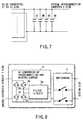
- FIG. 4is a block diagram schematically showing an energy conversion apparatus according to an embodiment of the present invention.
- a plurality of photovoltaic arrays 11 to 14are disposed on the east, west, south and north sides of a hip roof, as shown in, e.g. FIG. 1.
- the photovoltaic arrays 11 to 14convert solar energy to DC power and produce DC currents.
- DC-DC converters 21 to 24are provided in association with the respective photovoltaic arrays 11 to 14 and have functions (maximum power point tracking (MPPT) control functions) for tracking maximum points of power generated by the photovoltaic arrays 11 to 14.
- MPPTmaximum power point tracking
- the photovoltaic arrays 11 to 14are connected to the DC-DC converters 21 to 24 via terminal boards and DC switches, and not via such connection boxes as are used in the prior art.
- the conventional DC-DC converter 2is constructed such that a plurality of surge absorbers, block diodes and terminal boards are stored in a connection box having a DC switch connected to an input terminal of one power conditioner.
- DC power obtained from the DC-DC converters 21 to 24is gathered by an energy synthesis circuit 3.
- a system interconnection inverter 5for converting a DC power obtained from the energy synthesis circuit 3 to an AC power
- a switchgear 6for reversely supplying the AC power from the inverter 5 to a power system.
- each of the DC-DC converters 21 to 24comprises a filter 2a for removing noise from a DC voltage waveform obtained from each of the photovoltaic arrays 11 to 14; a chopper 2b for converting an output from the filter 2a to an AC; an insulating transformer 2c for boosting an output voltage from the chopper 2b and constituting a resonance-type power supply; a rectifier 2d for rectifying a secondary voltage of the transformer 2c; and a maximum power point tracking circuit 2e having a maximum power point tracking control function.
- This DC-DC converters 21 to 24are constructed to operate by the power from the photovoltaic arrays 11 to 14.
- the maximum power point tracking circuit 2eanalyzes an operation point of each of the photovoltaic arrays 11 to 14, according to a characteristic diagram of FIG. 6 showing the relationship between the voltage and the power/current of the photovoltaic array, finds a point (maximum power point) at which the generated power takes a maximum value, and operates each of the photovoltaic arrays 11 to 14, at this point.
- the energy synthesis circuit 3has a plurality of parallel-connected capacitors (the number of capacitors corresponding to the number of DC-DC converters 21 to 24; for example, four), for example, capacitors 3E, 3W, 3S and 3N each having a withstand voltage of 450V and a capacitance of 470 ⁇ F.
- the inverter 5has an inverter circuit wherein four semiconductor elements such as IGBTs (insulated gate bipolar transistors) 5a, 5b, 5c and 5d are bridge-connected and, for example, PWM-controlled by control circuits (not shown), thereby to convert a DC to an AC; and a filter circuit 5e for removing noise from an output current from the inverter circuit.
- IGBTsinsulated gate bipolar transistors
- This inverter 5may be operated by the power from energy synthesis circuit 3 described in detail hereinafter.
- an energy amount of the energy synthesis circuit 3is analyzed and an optimal power amount corresponding to the energy amount can be reversely supplied to the power system.
- control signalsare delivered from control circuits (not shown) to the IGBTs 5a, 5b, 5c and 5d, and the energy from the energy synthesis circuit 3 is temporally divided and transferred.
- the optimal power amount corresponding to the obtained energy amountis reversely supplied to the power system.
- a radio-frequency component of, e.g. 17 kHzis removed from the divided power by means of the filter circuit 5e, and the divided power is converted to the reversely supplied AC power.
- the operational advantage of the above-described embodimentwill now be described.
- the maximum points of power generated by the photovoltaic arrays 11 to 14are tracked by the DC-DC converters 21 to 24 connected to the photovoltaic arrays 11 to 14 respectively.
- the maximum power of each of the photovoltaic arrays 11 to 14can be derived.
- the power from the DC-DC converters 21 to 24is input to the energy synthesis circuit 3 and temporarily accumulated as static energy.
- the energy accumulated in the energy synthesis circuit 3is reversely supplied to the power system via the inverter circuit 5.
- each of the DC-DC converters 21 to 24constantly monitors the power of each of the photovoltaic arrays 11 to 14, and has the maximum power point tracking function, the operation voltage at which the input voltage of each photovoltaic array takes a maximum value can be quickly reached.
- each of DC-DC converters 21 to 24includes the insulating transformer 2c provided between the chopper 2b and rectifier 2d, the safety is enhanced. Besides, since each of DC-DC converters 21 to 24, constitutes a resonance-type power supply, the efficiency is enhanced and noise reduced. In addition, conventionally, the DC voltage of about 160V is 330V is input to this DC-DC converter 21 to 24 but, in the present invention, it is possible to use a lower voltage range of even within the range of low voltage, for example, such as the range of 25V to 50V and the range of 50V to 80V or 80V to 160V.
- the present inventionis not limited to the above-described embodiment, and various modifications may be made.
- a plurality of photovoltaic arraysare employed, but other DC power supply devices such as aerogenerators, fuel cell or various battery devices may be combined.
- DC powercan be derived efficiently.
- different kinds of DC power suppliesmay be combined. That is, in this case, it becomes possible to provide an energy conversion device, which can be used by connecting a plurality of DC power supply of different input voltages (and/or capacities) at the same time (in a hybrid form).
- the number of DC power supply apparatusphotovoltaic arrays
- the number of DC power supply apparatusis four, but it may be varied depending on the site for installation and other conditions.
- a charger, a battery, a DC-DC converter and a DC switchmay be connected on the input side of the energy synthesis circuit 3 or the input side of the energy synthesis circuit 3 in the above-described modifications. Thereby, an emergency backup power supply is provided in case of the absence of solar radiation or wind.
- the operation power supply of the DC-DC convertermay be derived from this DC power supply device.
Landscapes
- Engineering & Computer Science (AREA)
- Power Engineering (AREA)
- Control Of Electrical Variables (AREA)
- Photovoltaic Devices (AREA)
- Inverter Devices (AREA)
- Dc-Dc Converters (AREA)
Abstract
Description
The present invention relates to an energyconversion apparatus wherein a DC power obtained by DCpower supply apparatus such as a wind power generator orvarious battery apparatus or a photovoltaic array isinput to an inverter via a DC-DC converter and convertedto an AC power, and the AC power is supplied to a powersystem. The photovoltaic array is constructed accordingto the Japanese Industrial Standards (JIS). Thephotovoltaic array has a frame and/or a base, as well asother constituent elements. In the photovoltaic array,photovoltaic modules or photovoltaic panels aremechanically integrated and interconnected as one unit.The photovoltaic array constitutes one of DC powergenerators. The photovoltaic module is a minimum powergeneration unit wherein photovoltaic cells orphotovoltaic sub-modules are connected in series and/orin parallel and encapsulated in a casing for protectionagainst the environment, and the photovoltaic module hasexternal terminals to provide a prescribed output. Thephotovoltaic panel is an assembly of photovoltaicmodules which are mechanically coupled andinterconnected, thereby to permit installation on thesite.
In an example of this type of conventional energyconversion apparatus, a DC power obtained from aplurality of soler battery arrays is converted to an AC current by means of a single power conditioner andreversely supplied to a power system.
The power conditioner used in this case serves toenhance the characteristics of all photovoltaic arrays.The power conditioner has a function (maximum powerpoint tracking (MPPT) control function) for analyzing anoperation point (average value) at which the total powergenerated by all photovoltaic arrays takes a maximumvalue and thus tracking a maximum power point.
In a case of a plurality of photovoltaic arrays aredisposed on, for example, the roof, these arrays may beplaced separately on the east, west, south and northsides, as shown in FIG. 1. FIG. 1 shows an example of ahip roof. Photovoltaic arrays (PVE) 11, (PVW) 12, (PVS)13 and (PVN) 14, which provide array outputs of 500 W,500 W, 1 kW and 1 kW, respectively, are disposed on theeast, west, south and north sides.
In this example, even if no shadow is cast on anyof thephotovoltaic arrays 11 to 14, the modulesconstituting thephotovoltaic arrays 11 to 14 havedifferent temperatures due to a difference in intensityof solar radiation.
Where there is an obstacle in front of thephotovoltaic arrays 11 to 14, the time when a shadow iscast on thephotovoltaic arrays 11 to 14 will differdepending on thearrays 11 to 14 and thus the differencein module temperatures increases among thephotovoltaicarrays 11 to 14. In this case, as shown in FIG. 3, aDC-DC converter tracks and controls a maximum point ofgenerated power. DC currents from thephotovoltaicarrays 11 to 14, as shown in FIG. 3, are input to aDC-DC converter 2 having a maximum power trackingfunction. A point at which the generated power takes amaximum value is found, and thephotovoltaic arrays 11to 14 are operated at this point. An output from theDC-DC converter 2 is delivered to aninverter 5. Theinverter 5 performs DC/AC conversion and produces an AC power.
If the intensity in solar radiation and the moduletemperature varies, however, the operation voltage atwhich the optimal voltage or maximum output is obtainedvaries similarly. Consequently, the power generationefficiency of the entire system deteriorates.
As has been described above, in the conventionalenergy conversion apparatus, a single DC-DC convertertracks and controls the maximum point of the generatedpower of allphotovoltaic arrays 11 to 14. As a result,the power generation efficiency of the entire systemdeteriorates.
The object of the present invention is to providean energy conversion apparatus capable of efficientlytaking out a DC power, or an energy conversion apparatuscapable of enhancing a power generation efficiency ofthe entire system.
The first energy conversion device of the presentinvention is characterized by comprising: at least twoDC power supplies; at least two DC-DC convertersconnected independently to at least two DC powersupplies respectively, each of at least two DC-DCconverters having a function of efficiently taking outpower supplied from an associated one of at least two DCpower supplies, respectively; an energy synthesiscircuit for gathering DC power obtained from at leasttwo DC-DC converters; and an inverter for converting thegathered DC power from the energy synthesis circuit toan AC power and supplying the AC power to a power system.Here, at least two DC power supplies include at leastone of a photovoltaic array, a fuel cell, and anaerogenerator as the DC power sully. Thus, any powersupply may be applied as DC power supply.
Since DC-DC converters which can be independentlycontrolled corresponding to each of DC power supplies,which are not limited to one kind, are connected, andenergy gathering means gathers and supplies to the inverter after the maximum power is obtained from eachDC power supply respectively, the DC power can beefficiently taken out.
Preferred manners of the first and second energyconversion apparatus are as follows
Since DC-DC converters are connected correspondingto each DC power supply (that is, which can beconsidered as DC power supplies such as a photovoltaicarray, a fuel battery or a aerogenerator), respectively,and the output of each DC-DC converter is gathered bythe energy gathering means and supplied to the inverter,the power generation efficiency of the entire systemimproves.
As has been described above, the present inventioncan provide an energy conversion apparatus capable ofefficiently taking out a DC power, or an energyconversion apparatus capable of enhancing a powergeneration efficiency of the entire system.
This summary of the invention does not necessarilydescribe all necessary features so that the inventionmay also be a sub-combination of these describedfeatures.
The invention can be more fully understood from thefollowing detailed description when taken in conjunctionwith the accompanying drawings, in which:
An embodiment of the present invention will now bedescribed with reference to the accompanying drawings.
FIG. 4 is a block diagram schematically showing anenergy conversion apparatus according to an embodimentof the present invention. A plurality ofphotovoltaicarrays 11 to 14 are disposed on the east, west, southand north sides of a hip roof, as shown in, e.g. FIG. 1.Thephotovoltaic arrays 11 to 14 convert solar energy toDC power and produce DC currents.
DC-DC converters 21 to 24 (to be described later indetail) are provided in association with the respectivephotovoltaic arrays 11 to 14 and have functions (maximumpower point tracking (MPPT) control functions) fortracking maximum points of power generated by thephotovoltaic arrays 11 to 14.
Thephotovoltaic arrays 11 to 14 are connected tothe DC-DC converters 21 to 24 via terminal boards and DCswitches, and not via such connection boxes as are usedin the prior art. Specifically, the conventional DC-DCconverter 2 is constructed such that a plurality ofsurge absorbers, block diodes and terminal boards arestored in a connection box having a DC switch connectedto an input terminal of one power conditioner.
DC power obtained from the DC-DC converters 21 to24 is gathered by anenergy synthesis circuit 3.
There are also provided asystem interconnectioninverter 5 for converting a DC power obtained from theenergy synthesis circuit 3 to an AC power, and aswitchgear 6 for reversely supplying the AC power fromtheinverter 5 to a power system.
Since the DC-DC converters 21 to 24 have the samestructure, only one is shown here. As is shown inFIG. 5, each of the DC-DC converters 21 to 24, comprisesafilter 2a for removing noise from a DC voltagewaveform obtained from each of thephotovoltaic arrays 11 to 14; achopper 2b for converting an output from thefilter 2a to an AC; aninsulating transformer 2c forboosting an output voltage from thechopper 2b andconstituting a resonance-type power supply; arectifier 2d for rectifying a secondary voltage of thetransformer 2c; and a maximum powerpoint tracking circuit 2e havinga maximum power point tracking control function. ThisDC-DC converters 21 to 24 are constructed to operate bythe power from thephotovoltaic arrays 11 to 14.
The function of the maximum powerpoint trackingcircuit 2e will now be described. The maximum powerpoint tracking circuit 2e analyzes an operation point ofeach of thephotovoltaic arrays 11 to 14, according to acharacteristic diagram of FIG. 6 showing therelationship between the voltage and the power/currentof the photovoltaic array, finds a point (maximum powerpoint) at which the generated power takes a maximumvalue, and operates each of thephotovoltaic arrays 11to 14, at this point.
The reason why the maximum power points of therespective DC-DC converters 21 to 24 are found as in theabove embodiment will be described. Wherephotovoltaicarrays 11 to 14 are disposed on a hip roof, for example,the angles of incidence of solar radiation on thephotovoltaic arrays 11 to 14 provided on the east, west,south and north sides may vary from one another. Inother words, where the photovoltaic arrays are providedon the entire roof, the operation points at which themaximum powers are obtained from thephotovoltaic arrays 11 to 14 may differ from one another.
As is shown in FIG. 7, theenergy synthesis circuit 3 has a plurality of parallel-connected capacitors (thenumber of capacitors corresponding to the number ofDC-DC converters 21 to 24; for example, four), forexample,capacitors
As is shown in FIG. 8, theinverter 5 has aninverter circuit wherein four semiconductor elements such as IGBTs (insulated gate bipolar transistors) 5a,5b, 5c and 5d are bridge-connected and, for example,PWM-controlled by control circuits (not shown), therebyto convert a DC to an AC; and afilter circuit 5e forremoving noise from an output current from the invertercircuit. Thisinverter 5 may be operated by the powerfromenergy synthesis circuit 3 described in detailhereinafter.
With this structure, an energy amount of theenergysynthesis circuit 3 is analyzed and an optimal poweramount corresponding to the energy amount can bereversely supplied to the power system.
Specifically, control signals are delivered fromcontrol circuits (not shown) to theIGBTs energy synthesis circuit 3is temporally divided and transferred. Thus, theoptimal power amount corresponding to the obtainedenergy amount is reversely supplied to the power system.A radio-frequency component of, e.g. 17 kHz is removedfrom the divided power by means of thefilter circuit 5e,and the divided power is converted to the reverselysupplied AC power.
The operational advantage of the above-describedembodiment will now be described. The maximum points ofpower generated by thephotovoltaic arrays 11 to 14 aretracked by the DC-DC converters 21 to 24 connected tothephotovoltaic arrays 11 to 14 respectively. Thus,the maximum power of each of thephotovoltaic arrays 11to 14 can be derived.
The power from the DC-DC converters 21 to 24 isinput to theenergy synthesis circuit 3 and temporarilyaccumulated as static energy.
The energy accumulated in theenergy synthesiscircuit 3 is reversely supplied to the power system viatheinverter circuit 5.
Since the DC-DC converters 21 to 24 for trackingmaximum power points are connected to thephotovoltaic arrays 11 to 14 respectively, the power generationefficiency of the entire system increases.
Since each of the DC-DC converters 21 to 24,constantly monitors the power of each of thephotovoltaic arrays 11 to 14, and has the maximum powerpoint tracking function, the operation voltage at whichthe input voltage of each photovoltaic array takes amaximum value can be quickly reached.
Since each of DC-DC converters 21 to 24, includesthe insulatingtransformer 2c provided between thechopper 2b andrectifier 2d, the safety is enhanced.Besides, since each of DC-DC converters 21 to 24,constitutes a resonance-type power supply, theefficiency is enhanced and noise reduced. In addition,conventionally, the DC voltage of about 160V is 330V isinput to this DC-DC converter 21 to 24 but, in thepresent invention, it is possible to use a lower voltagerange of even within the range of low voltage, forexample, such as the range of 25V to 50V and the rangeof 50V to 80V or 80V to 160V.
The present invention is not limited to the above-describedembodiment, and various modifications may bemade. In the above embodiment, a plurality ofphotovoltaic arrays are employed, but other DC powersupply devices such as aerogenerators, fuel cell orvarious battery devices may be combined. With thisstructure, DC power can be derived efficiently.Furthermore, different kinds of DC power supplies may becombined. That is, in this case, it becomes possible toprovide an energy conversion device, which can be usedby connecting a plurality of DC power supply ofdifferent input voltages (and/or capacities) at the sametime (in a hybrid form). In the above embodiment, thenumber of DC power supply apparatus (photovoltaicarrays) is four, but it may be varied depending on thesite for installation and other conditions.
In the energy conversion apparatus shown in FIG. 4,a charger, a battery, a DC-DC converter and a DC switchmay be connected on the input side of theenergysynthesis circuit 3 or the input side of theenergysynthesis circuit 3 in the above-described modifications.Thereby, an emergency backup power supply is provided incase of the absence of solar radiation or wind.
In a case that any of the above-described variousDC power supply devices is connected to the DC-DCconverter via the terminal board and DC switch, theoperation power supply of the DC-DC converter may bederived from this DC power supply device.
Claims (8)
- An energy conversion apparatus characterized bycomprising:at least two DC power supplies (11-14);at least two DC-DC converters (21-24) connectedindependently to said at least two DC power suppliesrespectively, each of said at least two DC-DC convertershaving a function of efficiently taking out powersupplied from an associated one of said at least two DCpower supplies, respectively;an energy synthesis circuit (3) for gathering DCpower obtained from said at least two DC-DC converters;andan inverter (5) for converting the gathered DCpower from said energy synthesis circuit to an AC powerand supplying the AC power to a power system.
- The energy conversion apparatus according toclaim 1, characterized in that said at least two DCpower supplies include at least one of a photovoltaicarray, a fuel cell, and an aerogenerator as said DCpower sully.
- The energy conversion apparatus according toclaim 1 or claim 2, characterized in that each of saidDC-DC converters (21-24) has an insulating transformer(2c) constituting a resonance-type power supply, and amaximum power point tracking circuit (2e) for constantlymonitoring power of an associated one of saidphotovoltaic arrays and controlling an operation voltageof said associated one of said photovoltaic arrays suchthat an input power of said associated one of saidphotovoltaic arrays takes a maximum value.
- The energy conversion apparatus according toclaim 1 or claim 2, characterized in that said DC powersupplied supply a power supply to said DC-DC convertersand said DC-DC converters is operated by the powersupply.
- The energy conversion apparatus according toclaim 1 or claim 2, characterized in that said energysynthesis circuit (3) has capacitors (3E-3N) the numberof which corresponds to the number of said DC-DCconverters.
- The energy conversion apparatus according toclaim 1 or claim 2, characterized in that said DC powersupplied supply a power supply to said DC-DC convertersand said DC-DC converters is operated by the powersupply.
- The energy conversion apparatus according toclaim 1 or claim 2, characterized in that said DC-DCconverters are used by combining an arbitrary number ofDC-DC converters, capacities and input voltages with atleast two thereof.
- The energy conversion apparatus according toclaim 1 or claim 2, characterized in that said at leasttwo DC power supplies (11-14) are connected to said atleast two DC-DC converters via terminal boards and DCswitches.
Applications Claiming Priority (2)
| Application Number | Priority Date | Filing Date | Title |
|---|---|---|---|
| JP7501499 | 1999-03-19 | ||
| JP7501499 | 1999-03-19 |
Publications (2)
| Publication Number | Publication Date |
|---|---|
| EP1039620A2true EP1039620A2 (en) | 2000-09-27 |
| EP1039620A3 EP1039620A3 (en) | 2002-01-30 |
Family
ID=13563916
Family Applications (1)
| Application Number | Title | Priority Date | Filing Date |
|---|---|---|---|
| EP00105615AWithdrawnEP1039620A3 (en) | 1999-03-19 | 2000-03-16 | Energy conversion apparatus |
Country Status (2)
| Country | Link |
|---|---|
| EP (1) | EP1039620A3 (en) |
| AU (1) | AU2233700A (en) |
Cited By (59)
| Publication number | Priority date | Publication date | Assignee | Title |
|---|---|---|---|---|
| WO2005027300A1 (en)* | 2003-09-16 | 2005-03-24 | Solarit Ab | A module, a converter, a node, and a system |
| US9088178B2 (en) | 2006-12-06 | 2015-07-21 | Solaredge Technologies Ltd | Distributed power harvesting systems using DC power sources |
| US9112379B2 (en) | 2006-12-06 | 2015-08-18 | Solaredge Technologies Ltd. | Pairing of components in a direct current distributed power generation system |
| US9130401B2 (en) | 2006-12-06 | 2015-09-08 | Solaredge Technologies Ltd. | Distributed power harvesting systems using DC power sources |
| US9235228B2 (en) | 2012-03-05 | 2016-01-12 | Solaredge Technologies Ltd. | Direct current link circuit |
| US9291696B2 (en) | 2007-12-05 | 2016-03-22 | Solaredge Technologies Ltd. | Photovoltaic system power tracking method |
| US9318974B2 (en) | 2014-03-26 | 2016-04-19 | Solaredge Technologies Ltd. | Multi-level inverter with flying capacitor topology |
| US9362743B2 (en) | 2008-05-05 | 2016-06-07 | Solaredge Technologies Ltd. | Direct current power combiner |
| US9368964B2 (en) | 2006-12-06 | 2016-06-14 | Solaredge Technologies Ltd. | Distributed power system using direct current power sources |
| US9401599B2 (en) | 2010-12-09 | 2016-07-26 | Solaredge Technologies Ltd. | Disconnection of a string carrying direct current power |
| US9407161B2 (en) | 2007-12-05 | 2016-08-02 | Solaredge Technologies Ltd. | Parallel connected inverters |
| US9438035B2 (en) | 2003-05-28 | 2016-09-06 | Solaredge Technologies Ltd. | Power converter for a solar panel |
| US9537445B2 (en) | 2008-12-04 | 2017-01-03 | Solaredge Technologies Ltd. | Testing of a photovoltaic panel |
| US9543889B2 (en) | 2006-12-06 | 2017-01-10 | Solaredge Technologies Ltd. | Distributed power harvesting systems using DC power sources |
| US9548619B2 (en) | 2013-03-14 | 2017-01-17 | Solaredge Technologies Ltd. | Method and apparatus for storing and depleting energy |
| US9590526B2 (en) | 2006-12-06 | 2017-03-07 | Solaredge Technologies Ltd. | Safety mechanisms, wake up and shutdown methods in distributed power installations |
| EP3026521A4 (en)* | 2013-07-26 | 2017-04-05 | Kyocera Corporation | Power conversion device, power management method, and power management system |
| US9647442B2 (en) | 2010-11-09 | 2017-05-09 | Solaredge Technologies Ltd. | Arc detection and prevention in a power generation system |
| US9644993B2 (en) | 2006-12-06 | 2017-05-09 | Solaredge Technologies Ltd. | Monitoring of distributed power harvesting systems using DC power sources |
| US9673711B2 (en) | 2007-08-06 | 2017-06-06 | Solaredge Technologies Ltd. | Digital average input current control in power converter |
| US9680304B2 (en) | 2006-12-06 | 2017-06-13 | Solaredge Technologies Ltd. | Method for distributed power harvesting using DC power sources |
| US9812984B2 (en) | 2012-01-30 | 2017-11-07 | Solaredge Technologies Ltd. | Maximizing power in a photovoltaic distributed power system |
| US9819178B2 (en) | 2013-03-15 | 2017-11-14 | Solaredge Technologies Ltd. | Bypass mechanism |
| EP2454796A4 (en)* | 2009-07-16 | 2017-11-22 | General Cybernation Group, Inc. | Smart and scalable power inverters |
| US9831824B2 (en) | 2007-12-05 | 2017-11-28 | SolareEdge Technologies Ltd. | Current sensing on a MOSFET |
| US9853538B2 (en) | 2007-12-04 | 2017-12-26 | Solaredge Technologies Ltd. | Distributed power harvesting systems using DC power sources |
| US9853565B2 (en) | 2012-01-30 | 2017-12-26 | Solaredge Technologies Ltd. | Maximized power in a photovoltaic distributed power system |
| US9866098B2 (en) | 2011-01-12 | 2018-01-09 | Solaredge Technologies Ltd. | Serially connected inverters |
| US9869701B2 (en) | 2009-05-26 | 2018-01-16 | Solaredge Technologies Ltd. | Theft detection and prevention in a power generation system |
| US9876430B2 (en) | 2008-03-24 | 2018-01-23 | Solaredge Technologies Ltd. | Zero voltage switching |
| US9882508B2 (en) | 2014-01-10 | 2018-01-30 | Sumitomo Electric Industries, Ltd. | High-frequency switching type conversion device |
| US9923516B2 (en) | 2012-01-30 | 2018-03-20 | Solaredge Technologies Ltd. | Photovoltaic panel circuitry |
| US9941813B2 (en) | 2013-03-14 | 2018-04-10 | Solaredge Technologies Ltd. | High frequency multi-level inverter |
| US9960667B2 (en) | 2006-12-06 | 2018-05-01 | Solaredge Technologies Ltd. | System and method for protection during inverter shutdown in distributed power installations |
| US9966766B2 (en) | 2006-12-06 | 2018-05-08 | Solaredge Technologies Ltd. | Battery power delivery module |
| US20180131191A1 (en)* | 2010-06-09 | 2018-05-10 | Tigo Energy, Inc. | Method for Use of Static Inverters in Variable Energy Generation Environments |
| US10115841B2 (en) | 2012-06-04 | 2018-10-30 | Solaredge Technologies Ltd. | Integrated photovoltaic panel circuitry |
| US10230310B2 (en) | 2016-04-05 | 2019-03-12 | Solaredge Technologies Ltd | Safety switch for photovoltaic systems |
| US10277036B2 (en) | 2013-06-11 | 2019-04-30 | Sumitomo Electric Industries, Ltd. | Inverter device |
| US10355620B2 (en) | 2014-10-17 | 2019-07-16 | Sumitomo Electric Industries, Ltd. | Conversion device |
| US10396662B2 (en) | 2011-09-12 | 2019-08-27 | Solaredge Technologies Ltd | Direct current link circuit |
| US10673229B2 (en) | 2010-11-09 | 2020-06-02 | Solaredge Technologies Ltd. | Arc detection and prevention in a power generation system |
| US10673222B2 (en) | 2010-11-09 | 2020-06-02 | Solaredge Technologies Ltd. | Arc detection and prevention in a power generation system |
| US10931119B2 (en) | 2012-01-11 | 2021-02-23 | Solaredge Technologies Ltd. | Photovoltaic module |
| US11018623B2 (en) | 2016-04-05 | 2021-05-25 | Solaredge Technologies Ltd. | Safety switch for photovoltaic systems |
| US11177663B2 (en) | 2016-04-05 | 2021-11-16 | Solaredge Technologies Ltd. | Chain of power devices |
| US11264947B2 (en) | 2007-12-05 | 2022-03-01 | Solaredge Technologies Ltd. | Testing of a photovoltaic panel |
| US11296650B2 (en) | 2006-12-06 | 2022-04-05 | Solaredge Technologies Ltd. | System and method for protection during inverter shutdown in distributed power installations |
| US11309832B2 (en) | 2006-12-06 | 2022-04-19 | Solaredge Technologies Ltd. | Distributed power harvesting systems using DC power sources |
| CN115622190A (en)* | 2022-11-02 | 2023-01-17 | 杭州蔚斯博系统科技有限公司 | Mobile energy storage power supply equipment, controller and control method of internal power converter of mobile energy storage power supply equipment |
| US11569659B2 (en) | 2006-12-06 | 2023-01-31 | Solaredge Technologies Ltd. | Distributed power harvesting systems using DC power sources |
| US11687112B2 (en) | 2006-12-06 | 2023-06-27 | Solaredge Technologies Ltd. | Distributed power harvesting systems using DC power sources |
| US11728768B2 (en) | 2006-12-06 | 2023-08-15 | Solaredge Technologies Ltd. | Pairing of components in a direct current distributed power generation system |
| US11735910B2 (en) | 2006-12-06 | 2023-08-22 | Solaredge Technologies Ltd. | Distributed power system using direct current power sources |
| US11855231B2 (en) | 2006-12-06 | 2023-12-26 | Solaredge Technologies Ltd. | Distributed power harvesting systems using DC power sources |
| US11881814B2 (en) | 2005-12-05 | 2024-01-23 | Solaredge Technologies Ltd. | Testing of a photovoltaic panel |
| US11888387B2 (en) | 2006-12-06 | 2024-01-30 | Solaredge Technologies Ltd. | Safety mechanisms, wake up and shutdown methods in distributed power installations |
| US12057807B2 (en) | 2016-04-05 | 2024-08-06 | Solaredge Technologies Ltd. | Chain of power devices |
| US12418177B2 (en) | 2009-10-24 | 2025-09-16 | Solaredge Technologies Ltd. | Distributed power system using direct current power sources |
Family Cites Families (2)
| Publication number | Priority date | Publication date | Assignee | Title |
|---|---|---|---|---|
| US4924170A (en)* | 1989-01-03 | 1990-05-08 | Unisys Corporation | Current sharing modular power supply |
| DE19739917A1 (en)* | 1997-09-11 | 1999-03-18 | Siemens Ag | System for supplying electromotive consumers with electrical energy |
- 2000
- 2000-03-16EPEP00105615Apatent/EP1039620A3/ennot_activeWithdrawn
- 2000-03-17AUAU22337/00Apatent/AU2233700A/ennot_activeAbandoned
Cited By (168)
| Publication number | Priority date | Publication date | Assignee | Title |
|---|---|---|---|---|
| US9438035B2 (en) | 2003-05-28 | 2016-09-06 | Solaredge Technologies Ltd. | Power converter for a solar panel |
| US10910834B2 (en) | 2003-05-28 | 2021-02-02 | Solaredge Technologies Ltd. | Power converter for a solar panel |
| US11075518B2 (en) | 2003-05-28 | 2021-07-27 | Solaredge Technologies Ltd. | Power converter for a solar panel |
| US11476663B2 (en) | 2003-05-28 | 2022-10-18 | Solaredge Technologies Ltd. | Power converter for a solar panel |
| US10135241B2 (en) | 2003-05-28 | 2018-11-20 | Solaredge Technologies, Ltd. | Power converter for a solar panel |
| US11658508B2 (en) | 2003-05-28 | 2023-05-23 | Solaredge Technologies Ltd. | Power converter for a solar panel |
| US11817699B2 (en) | 2003-05-28 | 2023-11-14 | Solaredge Technologies Ltd. | Power converter for a solar panel |
| US11824398B2 (en) | 2003-05-28 | 2023-11-21 | Solaredge Technologies Ltd. | Power converter for a solar panel |
| WO2005027300A1 (en)* | 2003-09-16 | 2005-03-24 | Solarit Ab | A module, a converter, a node, and a system |
| US11881814B2 (en) | 2005-12-05 | 2024-01-23 | Solaredge Technologies Ltd. | Testing of a photovoltaic panel |
| US11682918B2 (en) | 2006-12-06 | 2023-06-20 | Solaredge Technologies Ltd. | Battery power delivery module |
| US12316274B2 (en) | 2006-12-06 | 2025-05-27 | Solaredge Technologies Ltd. | Pairing of components in a direct current distributed power generation system |
| US12068599B2 (en) | 2006-12-06 | 2024-08-20 | Solaredge Technologies Ltd. | System and method for protection during inverter shutdown in distributed power installations |
| US9543889B2 (en) | 2006-12-06 | 2017-01-10 | Solaredge Technologies Ltd. | Distributed power harvesting systems using DC power sources |
| US12046940B2 (en) | 2006-12-06 | 2024-07-23 | Solaredge Technologies Ltd. | Battery power control |
| US9590526B2 (en) | 2006-12-06 | 2017-03-07 | Solaredge Technologies Ltd. | Safety mechanisms, wake up and shutdown methods in distributed power installations |
| US12032080B2 (en) | 2006-12-06 | 2024-07-09 | Solaredge Technologies Ltd. | Safety mechanisms, wake up and shutdown methods in distributed power installations |
| US12027849B2 (en) | 2006-12-06 | 2024-07-02 | Solaredge Technologies Ltd. | Distributed power system using direct current power sources |
| US12027970B2 (en) | 2006-12-06 | 2024-07-02 | Solaredge Technologies Ltd. | Safety mechanisms, wake up and shutdown methods in distributed power installations |
| US9644993B2 (en) | 2006-12-06 | 2017-05-09 | Solaredge Technologies Ltd. | Monitoring of distributed power harvesting systems using DC power sources |
| US9088178B2 (en) | 2006-12-06 | 2015-07-21 | Solaredge Technologies Ltd | Distributed power harvesting systems using DC power sources |
| US9680304B2 (en) | 2006-12-06 | 2017-06-13 | Solaredge Technologies Ltd. | Method for distributed power harvesting using DC power sources |
| US11962243B2 (en) | 2006-12-06 | 2024-04-16 | Solaredge Technologies Ltd. | Method for distributed power harvesting using DC power sources |
| US11961922B2 (en) | 2006-12-06 | 2024-04-16 | Solaredge Technologies Ltd. | Distributed power harvesting systems using DC power sources |
| US11888387B2 (en) | 2006-12-06 | 2024-01-30 | Solaredge Technologies Ltd. | Safety mechanisms, wake up and shutdown methods in distributed power installations |
| US12224706B2 (en) | 2006-12-06 | 2025-02-11 | Solaredge Technologies Ltd. | Pairing of components in a direct current distributed power generation system |
| US11031861B2 (en) | 2006-12-06 | 2021-06-08 | Solaredge Technologies Ltd. | System and method for protection during inverter shutdown in distributed power installations |
| US9853490B2 (en) | 2006-12-06 | 2017-12-26 | Solaredge Technologies Ltd. | Distributed power system using direct current power sources |
| US11855231B2 (en) | 2006-12-06 | 2023-12-26 | Solaredge Technologies Ltd. | Distributed power harvesting systems using DC power sources |
| US9368964B2 (en) | 2006-12-06 | 2016-06-14 | Solaredge Technologies Ltd. | Distributed power system using direct current power sources |
| US12276997B2 (en) | 2006-12-06 | 2025-04-15 | Solaredge Technologies Ltd. | Distributed power harvesting systems using DC power sources |
| US11735910B2 (en) | 2006-12-06 | 2023-08-22 | Solaredge Technologies Ltd. | Distributed power system using direct current power sources |
| US11728768B2 (en) | 2006-12-06 | 2023-08-15 | Solaredge Technologies Ltd. | Pairing of components in a direct current distributed power generation system |
| US11687112B2 (en) | 2006-12-06 | 2023-06-27 | Solaredge Technologies Ltd. | Distributed power harvesting systems using DC power sources |
| US11002774B2 (en) | 2006-12-06 | 2021-05-11 | Solaredge Technologies Ltd. | Monitoring of distributed power harvesting systems using DC power sources |
| US11658482B2 (en) | 2006-12-06 | 2023-05-23 | Solaredge Technologies Ltd. | Distributed power harvesting systems using DC power sources |
| US9948233B2 (en) | 2006-12-06 | 2018-04-17 | Solaredge Technologies Ltd. | Distributed power harvesting systems using DC power sources |
| US9960667B2 (en) | 2006-12-06 | 2018-05-01 | Solaredge Technologies Ltd. | System and method for protection during inverter shutdown in distributed power installations |
| US9960731B2 (en) | 2006-12-06 | 2018-05-01 | Solaredge Technologies Ltd. | Pairing of components in a direct current distributed power generation system |
| US9966766B2 (en) | 2006-12-06 | 2018-05-08 | Solaredge Technologies Ltd. | Battery power delivery module |
| US12281919B2 (en) | 2006-12-06 | 2025-04-22 | Solaredge Technologies Ltd. | Monitoring of distributed power harvesting systems using DC power sources |
| US12107417B2 (en) | 2006-12-06 | 2024-10-01 | Solaredge Technologies Ltd. | Distributed power harvesting systems using DC power sources |
| US11598652B2 (en) | 2006-12-06 | 2023-03-07 | Solaredge Technologies Ltd. | Monitoring of distributed power harvesting systems using DC power sources |
| US10097007B2 (en) | 2006-12-06 | 2018-10-09 | Solaredge Technologies Ltd. | Method for distributed power harvesting using DC power sources |
| US11594881B2 (en) | 2006-12-06 | 2023-02-28 | Solaredge Technologies Ltd. | Distributed power harvesting systems using DC power sources |
| US11043820B2 (en) | 2006-12-06 | 2021-06-22 | Solaredge Technologies Ltd. | Battery power delivery module |
| US12388492B2 (en) | 2006-12-06 | 2025-08-12 | Solaredge Technologies Ltd. | Safety mechanisms, wake up and shutdown methods in distributed power installations |
| US10230245B2 (en) | 2006-12-06 | 2019-03-12 | Solaredge Technologies Ltd | Battery power delivery module |
| US11594882B2 (en) | 2006-12-06 | 2023-02-28 | Solaredge Technologies Ltd. | Distributed power harvesting systems using DC power sources |
| US11594880B2 (en) | 2006-12-06 | 2023-02-28 | Solaredge Technologies Ltd. | Distributed power harvesting systems using DC power sources |
| US11063440B2 (en) | 2006-12-06 | 2021-07-13 | Solaredge Technologies Ltd. | Method for distributed power harvesting using DC power sources |
| US11579235B2 (en) | 2006-12-06 | 2023-02-14 | Solaredge Technologies Ltd. | Safety mechanisms, wake up and shutdown methods in distributed power installations |
| US11575260B2 (en) | 2006-12-06 | 2023-02-07 | Solaredge Technologies Ltd. | Distributed power harvesting systems using DC power sources |
| US10447150B2 (en) | 2006-12-06 | 2019-10-15 | Solaredge Technologies Ltd. | Distributed power harvesting systems using DC power sources |
| US11575261B2 (en) | 2006-12-06 | 2023-02-07 | Solaredge Technologies Ltd. | Distributed power harvesting systems using DC power sources |
| US11569660B2 (en) | 2006-12-06 | 2023-01-31 | Solaredge Technologies Ltd. | Distributed power harvesting systems using DC power sources |
| US11569659B2 (en) | 2006-12-06 | 2023-01-31 | Solaredge Technologies Ltd. | Distributed power harvesting systems using DC power sources |
| US9112379B2 (en) | 2006-12-06 | 2015-08-18 | Solaredge Technologies Ltd. | Pairing of components in a direct current distributed power generation system |
| US11476799B2 (en) | 2006-12-06 | 2022-10-18 | Solaredge Technologies Ltd. | Distributed power harvesting systems using DC power sources |
| US10637393B2 (en) | 2006-12-06 | 2020-04-28 | Solaredge Technologies Ltd. | Distributed power harvesting systems using DC power sources |
| US9130401B2 (en) | 2006-12-06 | 2015-09-08 | Solaredge Technologies Ltd. | Distributed power harvesting systems using DC power sources |
| US11309832B2 (en) | 2006-12-06 | 2022-04-19 | Solaredge Technologies Ltd. | Distributed power harvesting systems using DC power sources |
| US11296650B2 (en) | 2006-12-06 | 2022-04-05 | Solaredge Technologies Ltd. | System and method for protection during inverter shutdown in distributed power installations |
| US11183922B2 (en) | 2006-12-06 | 2021-11-23 | Solaredge Technologies Ltd. | Distributed power harvesting systems using DC power sources |
| US10673253B2 (en) | 2006-12-06 | 2020-06-02 | Solaredge Technologies Ltd. | Battery power delivery module |
| US11073543B2 (en) | 2006-12-06 | 2021-07-27 | Solaredge Technologies Ltd. | Monitoring of distributed power harvesting systems using DC power sources |
| US10516336B2 (en) | 2007-08-06 | 2019-12-24 | Solaredge Technologies Ltd. | Digital average input current control in power converter |
| US11594968B2 (en) | 2007-08-06 | 2023-02-28 | Solaredge Technologies Ltd. | Digital average input current control in power converter |
| US10116217B2 (en) | 2007-08-06 | 2018-10-30 | Solaredge Technologies Ltd. | Digital average input current control in power converter |
| US9673711B2 (en) | 2007-08-06 | 2017-06-06 | Solaredge Technologies Ltd. | Digital average input current control in power converter |
| US9853538B2 (en) | 2007-12-04 | 2017-12-26 | Solaredge Technologies Ltd. | Distributed power harvesting systems using DC power sources |
| US9979280B2 (en) | 2007-12-05 | 2018-05-22 | Solaredge Technologies Ltd. | Parallel connected inverters |
| US9291696B2 (en) | 2007-12-05 | 2016-03-22 | Solaredge Technologies Ltd. | Photovoltaic system power tracking method |
| US12055647B2 (en) | 2007-12-05 | 2024-08-06 | Solaredge Technologies Ltd. | Parallel connected inverters |
| US11183969B2 (en) | 2007-12-05 | 2021-11-23 | Solaredge Technologies Ltd. | Testing of a photovoltaic panel |
| US11894806B2 (en) | 2007-12-05 | 2024-02-06 | Solaredge Technologies Ltd. | Testing of a photovoltaic panel |
| US9831824B2 (en) | 2007-12-05 | 2017-11-28 | SolareEdge Technologies Ltd. | Current sensing on a MOSFET |
| US9407161B2 (en) | 2007-12-05 | 2016-08-02 | Solaredge Technologies Ltd. | Parallel connected inverters |
| US11183923B2 (en) | 2007-12-05 | 2021-11-23 | Solaredge Technologies Ltd. | Parallel connected inverters |
| US11693080B2 (en) | 2007-12-05 | 2023-07-04 | Solaredge Technologies Ltd. | Parallel connected inverters |
| US10644589B2 (en) | 2007-12-05 | 2020-05-05 | Solaredge Technologies Ltd. | Parallel connected inverters |
| US10693415B2 (en) | 2007-12-05 | 2020-06-23 | Solaredge Technologies Ltd. | Testing of a photovoltaic panel |
| US11264947B2 (en) | 2007-12-05 | 2022-03-01 | Solaredge Technologies Ltd. | Testing of a photovoltaic panel |
| US9876430B2 (en) | 2008-03-24 | 2018-01-23 | Solaredge Technologies Ltd. | Zero voltage switching |
| US10468878B2 (en) | 2008-05-05 | 2019-11-05 | Solaredge Technologies Ltd. | Direct current power combiner |
| US12218498B2 (en) | 2008-05-05 | 2025-02-04 | Solaredge Technologies Ltd. | Direct current power combiner |
| US11424616B2 (en) | 2008-05-05 | 2022-08-23 | Solaredge Technologies Ltd. | Direct current power combiner |
| US9362743B2 (en) | 2008-05-05 | 2016-06-07 | Solaredge Technologies Ltd. | Direct current power combiner |
| US10461687B2 (en) | 2008-12-04 | 2019-10-29 | Solaredge Technologies Ltd. | Testing of a photovoltaic panel |
| US9537445B2 (en) | 2008-12-04 | 2017-01-03 | Solaredge Technologies Ltd. | Testing of a photovoltaic panel |
| US9869701B2 (en) | 2009-05-26 | 2018-01-16 | Solaredge Technologies Ltd. | Theft detection and prevention in a power generation system |
| US10969412B2 (en) | 2009-05-26 | 2021-04-06 | Solaredge Technologies Ltd. | Theft detection and prevention in a power generation system |
| US11867729B2 (en) | 2009-05-26 | 2024-01-09 | Solaredge Technologies Ltd. | Theft detection and prevention in a power generation system |
| US12306215B2 (en) | 2009-05-26 | 2025-05-20 | Solaredge Technologies Ltd. | Theft detection and prevention in a power generation system |
| EP2454796A4 (en)* | 2009-07-16 | 2017-11-22 | General Cybernation Group, Inc. | Smart and scalable power inverters |
| US12418177B2 (en) | 2009-10-24 | 2025-09-16 | Solaredge Technologies Ltd. | Distributed power system using direct current power sources |
| US20180131191A1 (en)* | 2010-06-09 | 2018-05-10 | Tigo Energy, Inc. | Method for Use of Static Inverters in Variable Energy Generation Environments |
| US10454275B2 (en)* | 2010-06-09 | 2019-10-22 | Tigo Energy, Inc. | Method for use of static inverters in variable energy generation environments |
| US10673229B2 (en) | 2010-11-09 | 2020-06-02 | Solaredge Technologies Ltd. | Arc detection and prevention in a power generation system |
| US10931228B2 (en) | 2010-11-09 | 2021-02-23 | Solaredge Technologies Ftd. | Arc detection and prevention in a power generation system |
| US9647442B2 (en) | 2010-11-09 | 2017-05-09 | Solaredge Technologies Ltd. | Arc detection and prevention in a power generation system |
| US11489330B2 (en) | 2010-11-09 | 2022-11-01 | Solaredge Technologies Ltd. | Arc detection and prevention in a power generation system |
| US12003215B2 (en) | 2010-11-09 | 2024-06-04 | Solaredge Technologies Ltd. | Arc detection and prevention in a power generation system |
| US12407158B2 (en) | 2010-11-09 | 2025-09-02 | Solaredge Technologies Ltd. | Arc detection and prevention in a power generation system |
| US11070051B2 (en) | 2010-11-09 | 2021-07-20 | Solaredge Technologies Ltd. | Arc detection and prevention in a power generation system |
| US10673222B2 (en) | 2010-11-09 | 2020-06-02 | Solaredge Technologies Ltd. | Arc detection and prevention in a power generation system |
| US11349432B2 (en) | 2010-11-09 | 2022-05-31 | Solaredge Technologies Ltd. | Arc detection and prevention in a power generation system |
| US9401599B2 (en) | 2010-12-09 | 2016-07-26 | Solaredge Technologies Ltd. | Disconnection of a string carrying direct current power |
| US9935458B2 (en) | 2010-12-09 | 2018-04-03 | Solaredge Technologies Ltd. | Disconnection of a string carrying direct current power |
| US12295184B2 (en) | 2010-12-09 | 2025-05-06 | Solaredge Technologies Ltd. | Disconnection of a string carrying direct current power |
| US11996488B2 (en) | 2010-12-09 | 2024-05-28 | Solaredge Technologies Ltd. | Disconnection of a string carrying direct current power |
| US11271394B2 (en) | 2010-12-09 | 2022-03-08 | Solaredge Technologies Ltd. | Disconnection of a string carrying direct current power |
| US10666125B2 (en) | 2011-01-12 | 2020-05-26 | Solaredge Technologies Ltd. | Serially connected inverters |
| US12218505B2 (en) | 2011-01-12 | 2025-02-04 | Solaredge Technologies Ltd. | Serially connected inverters |
| US9866098B2 (en) | 2011-01-12 | 2018-01-09 | Solaredge Technologies Ltd. | Serially connected inverters |
| US11205946B2 (en) | 2011-01-12 | 2021-12-21 | Solaredge Technologies Ltd. | Serially connected inverters |
| US10396662B2 (en) | 2011-09-12 | 2019-08-27 | Solaredge Technologies Ltd | Direct current link circuit |
| US10931119B2 (en) | 2012-01-11 | 2021-02-23 | Solaredge Technologies Ltd. | Photovoltaic module |
| US11979037B2 (en) | 2012-01-11 | 2024-05-07 | Solaredge Technologies Ltd. | Photovoltaic module |
| US12191668B2 (en) | 2012-01-30 | 2025-01-07 | Solaredge Technologies Ltd. | Maximizing power in a photovoltaic distributed power system |
| US9853565B2 (en) | 2012-01-30 | 2017-12-26 | Solaredge Technologies Ltd. | Maximized power in a photovoltaic distributed power system |
| US11183968B2 (en) | 2012-01-30 | 2021-11-23 | Solaredge Technologies Ltd. | Photovoltaic panel circuitry |
| US10992238B2 (en) | 2012-01-30 | 2021-04-27 | Solaredge Technologies Ltd. | Maximizing power in a photovoltaic distributed power system |
| US11929620B2 (en) | 2012-01-30 | 2024-03-12 | Solaredge Technologies Ltd. | Maximizing power in a photovoltaic distributed power system |
| US10608553B2 (en) | 2012-01-30 | 2020-03-31 | Solaredge Technologies Ltd. | Maximizing power in a photovoltaic distributed power system |
| US10381977B2 (en) | 2012-01-30 | 2019-08-13 | Solaredge Technologies Ltd | Photovoltaic panel circuitry |
| US9923516B2 (en) | 2012-01-30 | 2018-03-20 | Solaredge Technologies Ltd. | Photovoltaic panel circuitry |
| US11620885B2 (en) | 2012-01-30 | 2023-04-04 | Solaredge Technologies Ltd. | Photovoltaic panel circuitry |
| US9812984B2 (en) | 2012-01-30 | 2017-11-07 | Solaredge Technologies Ltd. | Maximizing power in a photovoltaic distributed power system |
| US12094306B2 (en) | 2012-01-30 | 2024-09-17 | Solaredge Technologies Ltd. | Photovoltaic panel circuitry |
| US10007288B2 (en) | 2012-03-05 | 2018-06-26 | Solaredge Technologies Ltd. | Direct current link circuit |
| US9235228B2 (en) | 2012-03-05 | 2016-01-12 | Solaredge Technologies Ltd. | Direct current link circuit |
| US9639106B2 (en) | 2012-03-05 | 2017-05-02 | Solaredge Technologies Ltd. | Direct current link circuit |
| US10115841B2 (en) | 2012-06-04 | 2018-10-30 | Solaredge Technologies Ltd. | Integrated photovoltaic panel circuitry |
| US12218628B2 (en) | 2012-06-04 | 2025-02-04 | Solaredge Technologies Ltd. | Integrated photovoltaic panel circuitry |
| US11177768B2 (en) | 2012-06-04 | 2021-11-16 | Solaredge Technologies Ltd. | Integrated photovoltaic panel circuitry |
| US9941813B2 (en) | 2013-03-14 | 2018-04-10 | Solaredge Technologies Ltd. | High frequency multi-level inverter |
| US9548619B2 (en) | 2013-03-14 | 2017-01-17 | Solaredge Technologies Ltd. | Method and apparatus for storing and depleting energy |
| US12255457B2 (en) | 2013-03-14 | 2025-03-18 | Solaredge Technologies Ltd. | Method and apparatus for storing and depleting energy |
| US11545912B2 (en) | 2013-03-14 | 2023-01-03 | Solaredge Technologies Ltd. | High frequency multi-level inverter |
| US12003107B2 (en) | 2013-03-14 | 2024-06-04 | Solaredge Technologies Ltd. | Method and apparatus for storing and depleting energy |
| US11742777B2 (en) | 2013-03-14 | 2023-08-29 | Solaredge Technologies Ltd. | High frequency multi-level inverter |
| US12119758B2 (en) | 2013-03-14 | 2024-10-15 | Solaredge Technologies Ltd. | High frequency multi-level inverter |
| US10778025B2 (en) | 2013-03-14 | 2020-09-15 | Solaredge Technologies Ltd. | Method and apparatus for storing and depleting energy |
| US10651647B2 (en) | 2013-03-15 | 2020-05-12 | Solaredge Technologies Ltd. | Bypass mechanism |
| US12132125B2 (en) | 2013-03-15 | 2024-10-29 | Solaredge Technologies Ltd. | Bypass mechanism |
| US9819178B2 (en) | 2013-03-15 | 2017-11-14 | Solaredge Technologies Ltd. | Bypass mechanism |
| US11424617B2 (en) | 2013-03-15 | 2022-08-23 | Solaredge Technologies Ltd. | Bypass mechanism |
| US10277036B2 (en) | 2013-06-11 | 2019-04-30 | Sumitomo Electric Industries, Ltd. | Inverter device |
| EP3026521A4 (en)* | 2013-07-26 | 2017-04-05 | Kyocera Corporation | Power conversion device, power management method, and power management system |
| US9882508B2 (en) | 2014-01-10 | 2018-01-30 | Sumitomo Electric Industries, Ltd. | High-frequency switching type conversion device |
| US9318974B2 (en) | 2014-03-26 | 2016-04-19 | Solaredge Technologies Ltd. | Multi-level inverter with flying capacitor topology |
| US12136890B2 (en) | 2014-03-26 | 2024-11-05 | Solaredge Technologies Ltd. | Multi-level inverter |
| US10886831B2 (en) | 2014-03-26 | 2021-01-05 | Solaredge Technologies Ltd. | Multi-level inverter |
| US11632058B2 (en) | 2014-03-26 | 2023-04-18 | Solaredge Technologies Ltd. | Multi-level inverter |
| US10886832B2 (en) | 2014-03-26 | 2021-01-05 | Solaredge Technologies Ltd. | Multi-level inverter |
| US11855552B2 (en) | 2014-03-26 | 2023-12-26 | Solaredge Technologies Ltd. | Multi-level inverter |
| US11296590B2 (en) | 2014-03-26 | 2022-04-05 | Solaredge Technologies Ltd. | Multi-level inverter |
| US10355620B2 (en) | 2014-10-17 | 2019-07-16 | Sumitomo Electric Industries, Ltd. | Conversion device |
| US12057807B2 (en) | 2016-04-05 | 2024-08-06 | Solaredge Technologies Ltd. | Chain of power devices |
| US11870250B2 (en) | 2016-04-05 | 2024-01-09 | Solaredge Technologies Ltd. | Chain of power devices |
| US11201476B2 (en) | 2016-04-05 | 2021-12-14 | Solaredge Technologies Ltd. | Photovoltaic power device and wiring |
| US11177663B2 (en) | 2016-04-05 | 2021-11-16 | Solaredge Technologies Ltd. | Chain of power devices |
| US12348182B2 (en) | 2016-04-05 | 2025-07-01 | Solaredge Technologies Ltd. | Safety switch for photovoltaic systems |
| US10230310B2 (en) | 2016-04-05 | 2019-03-12 | Solaredge Technologies Ltd | Safety switch for photovoltaic systems |
| US11018623B2 (en) | 2016-04-05 | 2021-05-25 | Solaredge Technologies Ltd. | Safety switch for photovoltaic systems |
| CN115622190A (en)* | 2022-11-02 | 2023-01-17 | 杭州蔚斯博系统科技有限公司 | Mobile energy storage power supply equipment, controller and control method of internal power converter of mobile energy storage power supply equipment |
| CN115622190B (en)* | 2022-11-02 | 2023-06-09 | 杭州蔚斯博系统科技有限公司 | Mobile energy storage power supply equipment, controller and internal power converter control method thereof |
Also Published As
| Publication number | Publication date |
|---|---|
| EP1039620A3 (en) | 2002-01-30 |
| AU2233700A (en) | 2000-09-21 |
Similar Documents
| Publication | Publication Date | Title |
|---|---|---|
| EP1039620A2 (en) | Energy conversion apparatus | |
| US8378656B2 (en) | Quasi-AC, photovoltaic module for unfolder photovoltaic inverter | |
| US6058032A (en) | Multiplex pulse-width modulation power converter | |
| US6448489B2 (en) | Solar generation system | |
| US7830036B2 (en) | Power electronic module pre-charge system and method | |
| EP3788697B1 (en) | Systems and methods of dc power conversion and transmission for solar fields | |
| US8929112B2 (en) | Circuit arrangement having a boost converter, and inverter circuit having such a circuit arrangement | |
| US9425703B2 (en) | AC/DC converter circuit for common three-phase AC input voltages and method of operating such converter circuit | |
| US20110103118A1 (en) | Non-isolated dc-dc converter assembly | |
| US20070273338A1 (en) | Transformerless Utility-Grid-Interactive Inverter | |
| US20080037305A1 (en) | Monopolar dc to bipolar dc to ac converter | |
| US9431898B2 (en) | Bidirectional DC-to-DC converter | |
| EP3920359B1 (en) | Inverter device and power supply system | |
| EP3297117A1 (en) | Distributed power system, dc-dc converter, and power conditioner | |
| EP4170879B1 (en) | Buck-assisted split-source inverter | |
| US20220103058A1 (en) | Method and Apparatus for Power Conversion | |
| JP2000341862A (en) | Energy conversion device | |
| KR20120064528A (en) | Apparatus for supplying dc power and method in grid-connected system | |
| US9042145B2 (en) | Circuit configuration with a step-up converter, and inverter circuit having such a circuit configuration | |
| TWI653812B (en) | DC/DC converter, power conditioner and power system | |
| Ramesh et al. | A cutting-edge single-stage buck-boost transformer-less inverter for 1-φ grid-tied solar PV schemes | |
| CN109672213B (en) | Power optimization system containing secondary optimization and optimization method thereof | |
| JP2002084763A (en) | Inverter device | |
| Ismeil et al. | Single-phase cascaded semi-Z-source inverter for photovoltaic applications | |
| Haripriya et al. | BLDC motor based solar water pumping system with grid interface |
Legal Events
| Date | Code | Title | Description |
|---|---|---|---|
| PUAI | Public reference made under article 153(3) epc to a published international application that has entered the european phase | Free format text:ORIGINAL CODE: 0009012 | |
| AK | Designated contracting states | Kind code of ref document:A2 Designated state(s):AT BE CH CY DE DK ES FI FR GB GR IE IT LI LU MC NL PT SE | |
| AX | Request for extension of the european patent | Free format text:AL;LT;LV;MK;RO;SI | |
| PUAL | Search report despatched | Free format text:ORIGINAL CODE: 0009013 | |
| RIC1 | Information provided on ipc code assigned before grant | Free format text:7H 02M 7/48 A, 7H 02J 1/10 B, 7H 02J 1/12 B | |
| AK | Designated contracting states | Kind code of ref document:A3 Designated state(s):AT BE CH CY DE DK ES FI FR GB GR IE IT LI LU MC NL PT SE | |
| AX | Request for extension of the european patent | Free format text:AL;LT;LV;MK;RO;SI | |
| 17P | Request for examination filed | Effective date:20020730 | |
| AKX | Designation fees paid | Free format text:AT BE CH CY DE DK ES FI FR GB GR IE IT LI LU MC NL PT SE | |
| STAA | Information on the status of an ep patent application or granted ep patent | Free format text:STATUS: THE APPLICATION HAS BEEN WITHDRAWN | |
| 18W | Application withdrawn | Withdrawal date:20021014 |