EP1034440B1 - A system for determining the spatial position and orientation of a body - Google Patents
A system for determining the spatial position and orientation of a bodyDownload PDFInfo
- Publication number
- EP1034440B1 EP1034440B1EP98958130AEP98958130AEP1034440B1EP 1034440 B1EP1034440 B1EP 1034440B1EP 98958130 AEP98958130 AEP 98958130AEP 98958130 AEP98958130 AEP 98958130AEP 1034440 B1EP1034440 B1EP 1034440B1
- Authority
- EP
- European Patent Office
- Prior art keywords
- marker
- markers
- energy
- segment
- pair
- Prior art date
- Legal status (The legal status is an assumption and is not a legal conclusion. Google has not performed a legal analysis and makes no representation as to the accuracy of the status listed.)
- Expired - Lifetime
Links
- 239000003550markerSubstances0.000claimsabstractdescription210
- 238000000034methodMethods0.000claimsabstractdescription33
- 230000004913activationEffects0.000claimsabstractdescription5
- 230000004044responseEffects0.000claimsabstractdescription4
- 238000012545processingMethods0.000claimsdescription27
- 238000004364calculation methodMethods0.000claimsdescription3
- 238000001514detection methodMethods0.000claimsdescription3
- 238000003491arrayMethods0.000claims5
- 230000008901benefitEffects0.000abstractdescription5
- 230000000712assemblyEffects0.000description13
- 238000000429assemblyMethods0.000description13
- 238000010586diagramMethods0.000description11
- 239000013598vectorSubstances0.000description9
- 238000012360testing methodMethods0.000description8
- 238000000605extractionMethods0.000description5
- 230000006870functionEffects0.000description3
- 238000013507mappingMethods0.000description3
- 238000005259measurementMethods0.000description3
- 230000008569processEffects0.000description3
- 238000000926separation methodMethods0.000description2
- 230000009466transformationEffects0.000description2
- 238000004458analytical methodMethods0.000description1
- 238000002591computed tomographyMethods0.000description1
- 238000004519manufacturing processMethods0.000description1
- 239000000463materialSubstances0.000description1
- 239000011159matrix materialSubstances0.000description1
- 238000012544monitoring processMethods0.000description1
- 238000003909pattern recognitionMethods0.000description1
- 238000005070samplingMethods0.000description1
- 238000001356surgical procedureMethods0.000description1
- 238000012795verificationMethods0.000description1
Images


Classifications
- G—PHYSICS
- G01—MEASURING; TESTING
- G01S—RADIO DIRECTION-FINDING; RADIO NAVIGATION; DETERMINING DISTANCE OR VELOCITY BY USE OF RADIO WAVES; LOCATING OR PRESENCE-DETECTING BY USE OF THE REFLECTION OR RERADIATION OF RADIO WAVES; ANALOGOUS ARRANGEMENTS USING OTHER WAVES
- G01S17/00—Systems using the reflection or reradiation of electromagnetic waves other than radio waves, e.g. lidar systems
- G01S17/87—Combinations of systems using electromagnetic waves other than radio waves
- G01S17/875—Combinations of systems using electromagnetic waves other than radio waves for determining attitude
- G—PHYSICS
- G01—MEASURING; TESTING
- G01S—RADIO DIRECTION-FINDING; RADIO NAVIGATION; DETERMINING DISTANCE OR VELOCITY BY USE OF RADIO WAVES; LOCATING OR PRESENCE-DETECTING BY USE OF THE REFLECTION OR RERADIATION OF RADIO WAVES; ANALOGOUS ARRANGEMENTS USING OTHER WAVES
- G01S5/00—Position-fixing by co-ordinating two or more direction or position line determinations; Position-fixing by co-ordinating two or more distance determinations
- G01S5/16—Position-fixing by co-ordinating two or more direction or position line determinations; Position-fixing by co-ordinating two or more distance determinations using electromagnetic waves other than radio waves
- G01S5/163—Determination of attitude
- G—PHYSICS
- G01—MEASURING; TESTING
- G01S—RADIO DIRECTION-FINDING; RADIO NAVIGATION; DETERMINING DISTANCE OR VELOCITY BY USE OF RADIO WAVES; LOCATING OR PRESENCE-DETECTING BY USE OF THE REFLECTION OR RERADIATION OF RADIO WAVES; ANALOGOUS ARRANGEMENTS USING OTHER WAVES
- G01S17/00—Systems using the reflection or reradiation of electromagnetic waves other than radio waves, e.g. lidar systems
- G01S17/74—Systems using reradiation of electromagnetic waves other than radio waves, e.g. IFF, i.e. identification of friend or foe
Definitions
- This inventionrelates to apparatus and methods for determining the spatial location and orientation of each of a plurality of bodies.
- Known systemsare available for determining the spatial position and angular orientation of a body (or object).
- One such systemincludes passive retroreflectors as point markers, or targets, affixed to the body, and a second system includes active radiating emitters as the affixed point markers. Both techniques operate by projecting the image of a highly contrasting marker onto spaced sensors and using mathematical processing to determine the three dimensional coordinates of each one of the point markers.
- 3Dthree dimensional coordinates
- x, y and z positions and pitch, yaw and roll angular orientationsare then used as discrete points, or may be considered as a set if their geometric arrangement is known, resulting in the determination of the position and angular orientation of the body (i.e., six degrees of freedom: x, y and z positions and pitch, yaw and roll angular orientations) in space relative to a three dimensional coordinate system centred at a preselected point in space, typically at a point fixed relative to the sensors.
- a pointing devicecan be made out of the body whereby the end tip of the pointing device is in a known position relative to the markers.
- Such a pointing devicecan be used as a digitizing pointer held by hand as in reverse engineering applications. An operator moves this pointing body to various known places on a manufactured component and the accuracy of the manufacturing processes is determined from analysis of the determined end tip position of the pointing device. This application requires a highly accurate system.
- the instrument poseis being tracked with respect to the patient.
- Certain surgical instrumentshave affixed to them markers. This information can be used to allow the surgeon to see where the instrument is pointing on a MR or CT scan, and what is beyond the end tip of the surgical instrument.
- This applicationalso requires a highly accurate system.
- multiple charge coupled device (CCD) sensorsare used to detect the energy emitted by the marker.
- a single point markeris energized per sensor cycle to emit infrared energy.
- the emitted energy focussed onto the sensoris collected (i.e. integrated) and shifted to the sensor processing circuitry.
- the markerIn order to determine the 3D position of the marker, the marker must be detected on at least three sensor axes (i.e. to cover a minimum of 3 orthogonal planes).
- an energy sourceis energized to emit infrared energy in the general direction of the retro-reflective marker.
- Multiple CCD sensorsare then used to detect the energy reflected by the marker.
- the reflected energy focussed onto the sensoris collected (i.e., integrated) and shifted to the sensor processing circuitry.
- the markerIn order,to determine the 3D position of the marker, the marker must be detected on at least three sensor axes (i.e. to cover a minimum of 3 orthogonal planes).
- US Patent 4 652 917describes a system for monitoring the position and attitude of a wing tip bearing a missile.
- One or two electronic camerasare mounted on the fuselage of the aircraft, and three rectangular target spots are marked on the wing near the missile. Images of the target spots are formed on array sensors in the cameras.
- An infra-red lampmay be provided to illuminate the target spots at night.
- the camerasare coupled to a computer that defines a target tracking gate of six by eight pixels for the image of each target spot.
- the target spotseach cover an area of four pixels on a camera sensor array.
- the location of the median of each target spot imageis determined by positioning the respective target tracking gate over the image so that the median of the image is at the median of the gate.
- Movement of the wing tipis monitored by tracking deviation of the median of each target spot image from the median of its tracking gate and repositioning the tracking gate.
- Separate processing channelsprocess the data relating to the three different target spots.
- the position and attitude, in terms of pitch, yaw, and roll of the wing tip,are calculated from the deviation data provided by tracking the three target spots.
- US Patent 4 652 917also proposes that individual target spots may be in the form of a pattern or set of high contrast markings or lines capable of recognition by appropriate pattern recognition components.
- a cost effective area array sensorwhich is capable of tracking multiple markers during a single sensor cycle.
- DeMenthonPatent No. 5,227,985
- Triangulation methodsalso called stereometric techniques, were rejected due to the costly hardware required to perform real-time calculations.
- Multiple marker triangulation methods with area array sensorshave the additional problem of poor marker identification, which is typically solved with human intervention.
- Prior systemscan operate poorly in the presence of real-life situations of stray IR sources and reflections that will appear to be unwanted and unexpected markers.
- Prior systemscan also operate poorly in the presence of multiple bodies in close proximity to each other.
- a preferred embodiment of the present inventionprovides a system for determining the spatial position and orientation of each of a plurality of bodies.
- Each one of the bodieshas at least three markers in a predetermined, relative geometric relationship.
- Each markeris either an active marker adapted to emit energy in response to an activation signal or a passive marker adapted to reflect energy impinging upon such passive marker from an activatable energy source.
- a common energy detectoris provided for detecting the energy emitted by an active marker or the energy reflected by a passive marker.
- a common processoris provided.
- the memoryhas stored therein the predetermined, relative geometric relation of the markers for each one of the bodies.
- the processorcompares the stored predetermined geometric relation of the markers for each of the bodies with the pattern of energy detected by the energy detector to identify the bodies emitting/or reflecting the detected energy.
- each bodycan be tracked using a very simple sequence of operation in real-time with robust positive marker identification by taking advantage of a simple marker placement methodology. Multiple bodies can thereby be tracked simultaneously.
- Each bodyhas its markers in a known and fixed relative geometry in which all the segment lengths amongst all pairs of all the markers are unique, where the term unique entails a threshold value of difference based on the accuracy of the system (i.e., the difference in the geometric relations of the markers for the bodies is detectable).
- Multiple objectscan be tracked simultaneously since pairs of like segments amongst all bodies being tracked have unique relative angles, again where the term unique entails a threshold value of difference based on the accuracy of the system.
- the marker geometrycan be collinear or coplanar as required by the applications.
- a systemadapted to track the pose of a body with 3 or greater markers in a known relative geometry, subject to simple placement rules, which are not limited to being non-coplanar or non-collinear.
- the systemis able to use a cost effective, low speed, area array sensors that can track multiple markers in a single sensor cycle, thus increasing the apparent sampling rate of each of the markers.
- the preferred systemuses a stereometric arrangement of sensors, thus providing adequate accuracy for high performance applications such as surgical application.
- the systemis able to use cost effective digital signal processors and simple processing calculations steps which will automatically and positively identify the discrete markers of the body in three-dimensions (3D) and operate in the presence of many false markers and multiple bodies in close proximity.
- the systemis adapted to determine the pose of one or more bodies in real-time in a closed form solution using a single sensor cycle image rather than using predictive methods to continue tracking the pose of a body given several sensor cycle images.
- systemis adapted to automatically recognize and track various bodies that are known in advance of tracking.
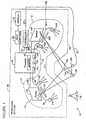
- a system 10for determining the spatial position and orientation of one or more, here a pair of, rigid bodies 11a, 11b, is provided.
- the rigid bodies 11a, 11bshown and described in more detail in FIG. 2, are different surgical instruments.
- rigid body 11ahas a plurality of, here two passive, retro-reflecting point markers 12a, 12c, and one active, emitting marker 12b affixed thereto.
- each of the energy retro-reflecting markers 12a, 12cincludes a sphere, affixable to body 11a, covered with a retro-reflective material as is generally available and well known in the art.
- the markers 12a, 12b, 12care affixed to body 11a in a predetermined, fixed relative geometric relationship.
- the predetermined, fixed relative geometric relationis defined by simple placement rules described below.
- the system 10includes a common energy detection system 14 for detecting both the energy emitted by the active marker 12b affixed to body 11a and the energy reflected by the passive markers 12a, 12c affixed to the body 11a.
- the common detector system 14includes a pair of spaced, left mounted and right mounted sensor assemblies 14L and 14R, respectively.
- Each one of the sensor assemblies 14L, 14Rincludes: a two-dimensional, charge couple device (CCD) sensor 18L, 18R (FIG. 1), respectively; a focusing lens 22L, 22R, respectively, as shown; and, a plurality of light energy emitting sources 24L, 24R (here infrared energy emitting diodes), respectively, as shown.
- CCDcharge couple device
- Each of the sensor assemblies 14R and 14Lhas its own u, v, z s co-ordinate system aligned with its associated directional infrared energy sources 24L, 24R, respectively.
- the light emitting sources 24L, 24Rare evenly distributed circumferentially about the z s axis of each of the sensor assemblies 14R and 14L, respectively.
- the plurality of light emitting sources 24L, 24Ris energized with electrical energy by a processor section 26.
- the processor section 26includes a processor 28, host computer 30, display 32 and controller 34.
- the processor 28energizes the light emitting sources 24L, 24R via a signal on line 36.
- the plurality of light emitting sources 24L, 24Roperate to produce an incident directional energy beam of infrared energy with a direction of propagation aimed along a directional axis which generally corresponds to the z s axis of each of the sensor assemblies 14L, 14R associated with that directional energy source 24L, 24R.
- the incident directional energy beam created by the directional infrared energy sourceis of a size, shape and intensity that corresponds to the volumetric field of view of its associated sensor assembly 14L, 14R and sufficient to provide an incident directional energy beam throughout the measurement volume.
- the sensor assemblies 14L, 14Rare each able to produce output signals on lines 39L, 39R, respectively, which represent the intensity of energy focused thereon. During each sensor cycle, the energy focused thereon is collected (i.e. integrated) and then shifted to the processor 28.
- the sensor assemblies 14L and 14Rare mounted to a fixed reference and are separated from each other by a predetermined distance, here 500 mm.
- the sensor assemblies 14L, 14Reach have a field of view sufficient to observe a common measurement volume of approximately 1m 3 centered along the z s axis at approximately 1.9m from the origin point which is midway between the lenses 22L and 22R.
- each of the sensor assemblies 14L and 14Rhas its own associated lens 22L, 22R, respectively, for focusing both the reflected energy from the energy retro-reflecting markers 12a, 12c and the emitted energy from the energy emitting marker 12b, in order to create a focused energy image of the emitted or reflected energy from the markers 12a, 12b, 12c respectively on the lenses 22L, 22R associated sensor assemblies 14R, 14L, respectively.
- the processor 28is coupled to the sensor assemblies 14L and 14R and determines the two-dimensional u, v positions of the focused energy image on each of the sensor assemblies 14L and 14R. Then, using the u, v position of the focused energy image of the same marker 12a, 12b, 12c on each of the sensor assemblies 14L and 14R to generate left and Right Sensor Energy Source Location Tables 50L, 50R (FIGS. 3 and 9A, 9B) and set the Left-Sources and Right Sources counters 51L, 51R, to be described.
- the processor 28is coupled to the host computer 30 in order that the spatial position of the bodies 11a, 11b can be displayed on display 32 or further processed by the host computer 30. As noted above, the processor 28 is coupled to the directional energy sources 24L, 24R in order that the processing section 26 can activate the directional energy sources 24R and 24L at appropriate times. The processor 28 is also coupled to the controller 34 in order that the processor 28 can signal the controller 34 to activate the energy emitting markers 12b at the required time via line 27.
- the active marker 12bis fed via a cable 27 (FIG. 1) to controller 34, as shown.
- the energy emitting marker 12binclude an infrared energy emitting diode of marker 12b which, upon being energized with electrical energy fed thereto by controller 34 via the cable 27, emits infrared light energy.
- infrared energy emitting diodesare generally available and well known in the art.
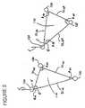
- the rigid bodies 11a and 11bare have affixed thereto markers 12a-12c and 12d-12f, respectively. It should first be understood that it is not relevant that marker 12a, and 12c are retro-reflective and marker 12b is active. This configuration is for example only and the methods described below are independent of the marker type.
- Each body 11a, 11bhas the markers 12a, 12b, 12c and 12d, 12e, 12f, respectively, affixed to it in a predetermined (i.e., known) and fixed relative geometry. Further, the relative geometry for the markers 12a, 12b and 12c must be detectably different from the relative geometry of markers 12c, 12d and 12f of body 11b. Thus, as shown in FIG.
- the markers 12a, 12b and 12c of body 11aare separated by line segments SLab, SLbc and SLac, respectively, as shown. Further, the line segments SLab, SLbc, and SLac intersect, as shown to form angles ⁇ ab, ⁇ bc, and ⁇ ac, as shown. Likewise, the markers 12d, 12e and 12f of body 11b are separated by line segments SLde, SLef and SLdf, respectively, as shown.
- segment length SLabmust vary in length from segment SLac and SLbc, as must segment length SLbc vary in length from segment SLac.
- the variance, ⁇in the preferred embodiment is 5.0 mm.
- Body 11ahas a pair of segments SLab, SLbc which are equal-in length to the pair of segments SLde, SLef on body 11b; these can still be tracked if the relative angle ⁇ ab between segment SLab, SLbc on body 11a is different than the relative angle ⁇ de between segment SLde, SLef on body 11b.
- the marker geometrycan be collinear, non-collinear, co-planar or non-coplanar, as required by the application.
- the pair of bodies 11a, 11bare tracked simultaneously if pairs of like segments amongst all bodies 11a, 11b being tracked have unique relative angles; again where the term unique is a threshold value difference based on the accuracy of the system 10. That is, the markers 12a-12c, 12d-12f are placed on bodies 11a, 11b, respectively to provide each one of the bodies 11a, 11b with a unique signature, or finger-print, that can be recognized and tracked by the processor 28.
- the processor 28has a memory 40 (FIG. 3) which stores three sets of Tables, 42-48; 50L, 50R, and 52; and 56-62.
- a first set of the Tablesi.e., A Rigid Body Definition Set of Tables, 42-48 defines the predetermined geometric relationship of the markers 12a-12d, 12e-12f for each one of the bodies 11a, 11b;
- a second set of the Tablesi.e., Sensor Generated Data Tables, 50L, 50R and 52
- a third set of Tablesi.e., Processing Tables, 56-62) which are generated by the processor while the rigid bodies 11a, 11b are being identified and tracked.
- These Tables(and Counters 51L, 51R and 53, to be described), reside in the processor 28 and are used by the processor 28 during the operating sequence
- the Rigid Body Definition Tablesinclude: a Marker Position Table, 42; a Marker Segment Table, 44; a Marker Segment Dot (•) Product Table, 46 and a Marker Segment Set Table, 48.
- These Rigid Body Definition Tables, 42-48are for all bodies 11a, 11b and contain a priori known information about geometric relationship of the markers 12a-12c and 12d-12f, that are affixed to rigid bodies 11a. 11b, respectively, to thereby provide each one of the bodies 11a, 11b with a unique signature, or finger-print, that can be recognized and tracked by the processor 28.
- These Rigid Body Definition Tables, 42-48are initialized once prior to the identification and subsequent tracking operations of the processor 28.
- Each rigid body 11a, 11bhas associated with it a Marker Position Table 42, as shown for body 11a in FIG. 11.
- the Marker Position Table 42includes the 3D position (X', Y', Z') of each marker 12a, 12b and 12c associated with the rigid body 11a, for example. Referring to FIG. 11, the Marker Position Table 42, is shown for body 11a, it being understood that Table 42 has a similar table for body 11b. The 3D position of marker 12a, 12b, and 12c is shown.
- Each rigid body 11a, 11bhas a Marker Segment Length Table 44, (FIG. 12) associated with it that contains the set of segment lengths of a body 11a, 11b.
- a segmentis considered the line joining a pair of markers 12a, 12b, 12c for body 11a and markers 12d, 12e and 12f for body 11b.
- body 11ahas segments SLab, SLbc, and SLac and body 11b has segments SLde, SLef and SLdf.
- the complete set of segments for a bodyis every combination of marker pairs.
- Nis the number of markers affixed to the body.
- Marker Segment Length Table 44is shown for body 11a.
- the segment lengths SLab, SLbc, and SLacare shown.
- Each rigid body 11a, 11bhas a Marker Segment Set Table 48 (FIG. 13) associated with it that contains the marker segment sets. There is one entry in the Table 48 for each marker. Each marker entry will contain 2 or more segments that are connected to this marker. There will be N-1 segments attached to each marker for an N marker body.
- FIG. 13shows the set of segments for a rigid body 11a.
- Each marker 12a, 12b, 12chas associated with it two segments (i.e., segment 1 and segment 2, in FIG. 13).
- marker 12ais attached to segments SLab and SLac
- marker 12bis attached to segments SLab and SLbc.
- Marker 12cis attached to segments SLac and SLbc. It is understood that a similar table would be for marker 11b.
- Each rigid bodyhas a Segment Dot (•) Product Table 46 (FIG. 14) associated with it that contains the list of dot (•) products between each combination of segments.
- the dot (•) productis used as a determination of the angle, ⁇ , between the segment lengths, SL, when the segments are treated as vectors transposed to the origin of X, Y, Z system 10 co-ordinate system.
- ⁇the angle between the segment lengths
- SLsegment lengths
- Nthe number of segments in the rigid body.
- the example FIG. 14shows the set of dot (•) products for body 11a.
- the dot (•) product for angle ⁇ a,b between segment lengths SLab and SLbcis shown to be 3600.
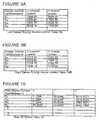
- the Sensor Generated Data Tables 50L, 50R and 52include: Left and Right Sensor Energy Source Location Tables 50L, 50R; and a Raw 3D Marker Table 52.
- the Left-Sources and Right-Sources Counters 51L, 51Rcontain the number of the energy spots detected on the left and right sensor 18L, 18R respectively.
- Each entrywill have a U and V value corresponding to the center of mass of the energy spot along the U axis and the V axis of the associated sensor 18L, 18R.
- there will be left and right sensor energy source Tables, 50L, 50R(FIG. 3).
- Raw 3D Marker Table 52There is single Raw 3D Marker Table 52, (FIGS. 3, 10) in memory 40 that contains a single entry for each determined but unqualified marker location (raw markers). Each entry has an X, Y and Z (i.e., the X, Y, Z system 10 co-ordinate system) value corresponding to the coordinate system of the position sensor with the origin midpoint between the image sensors 18L, 18R.
- the Raw Marker Counter 53contains the number of raw markers detected. Referring to FIG. 10, an example is given of 4 raw markers. In this example the markers 12a, 12b, and 12c of body 11a are detected and one stray unknown marker. The allocation of these markers R1-R4 is not known at this time with respect to markers 12a-12c and 12d-12f on body 11a and 11b, respectively. The sequence of operations will be used to determine the correspondence of these markers to body 11a or body 11b.
- the Processing Tablesare: a Segment Raw Marker Cross Reference Table 56; a Qualified Segment Table 58; a Measured Marker Position Table 60; and, a Calculated Rigid Body Position and Orientation (Pose) Table 62. These Processing Tables 56-62 are produced by the processor 28 for each of the rigid bodies 11a, 11b and are generated by the processor 28 while the rigid bodies are being recognized (i.e., identified) and tracked.
- Each rigid bodyhas a Segment Raw Marker Cross Reference Table 56 (FIGS. 3, 15) associated with it that contains all the raw marker 12a, 12b and 12c pairs that have a separation distance close to the defined segment length of the rigid body.
- the term closeis defined by a length difference between the defined segment and the segment under test, which is less than some predefined value (i.e., a distance detectable by the system 10). In the preferred embodiment this value is 1.5 mm.
- the following exampleillustrates pairs of markers that match the predefined segment lengths SLab, SLbc, SLac of the body 11a.
- the raw marker pair datais determined by the processor 28 in accordance with a method to be described in connection with FIG. 6.
- the two sets of four raw energy data S1-S8 detected by the right and left sensors 14L, 14R, FIGS. 9A, 9B)are converted by the processor 28 into four raw markers R1-R4 (in the system 10 X, Y, Z co-ordinate system) and are stored in the 3D Raw Marker Table, 52 (FIG. 10).
- R1-R4there are six segment lengths (i.e., SL12, SL13, SL14, SL23, SL24 and SL34).
- raw markers R1 and R2are separated by a segment length SL12 which is close to the length of segment SLab.
- Raw markers (R1, R4), (R3, R4), and (R2, R3)are all separated by a length close to length of segment SLbc. Also raw markers (R2, R4), and (R1, R3) are all separated by a length close to length of segment SLac. This data is stored in the Segment Raw Marker Cross Reference Table, 56 as indicated in FIG. 15.
- Each rigid body 11a, 11bhas a Measured Marker Position Table 60 (FIGS. 3, 17) associated with it that contains the 3D positions of the raw markers R1-R4 that have been identified, validated, and mapped to the body actual markers 12a-12c, 12d-12f.
- the example given in FIG. 17shows the measured position of markers 12a, 12b, and 12c of body 11a where actual marker 12a corresponds to raw marker R2, actual marker 12b corresponds to raw marker R4, and actual marker 12c corresponds to raw marker R1.
- Each rigid bodyhas a Calculated Rigid Body Position and Orientation Table 62 (FIGS. 3, 18) associated with it that contains the transformation of the rigid body.
- Thisis the pose that is determined from the Measured Marker Position Table 60 (FIG. 17) based on the Marker Position Table 42 (FIG. 11).
- the poseis the transformation that moves the Marker Position Table 42 into the same space X, Y, Z co-ordinate system of system 10, as shown in Measured Marker Position Table 60.
- the example shown in FIG. 18illustrates the pose of body 11a.
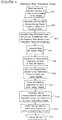
- Step 401the energy sources 24L and 24R (FIG. 1) and active marker 12b are activated. Referring to FIG. 1 these energy sources are focussed through the lens system 22L, 22R and project an image on the CCD sensors 18L, 18R. This image is scanned from the sensors 18L, 18R and any intensity above a certain threshold value will be analyzed by the processor 28.
- Step 402the position of the sensor energy sources are stored in Left and Right Sensor Energy Source Location Tables 50L, 50R (FIGS. 3, 9A, 9B). The position is in units of pixels.
- the horizontal axis of the sensoris called U and the vertical axis is called V.
- a left and right sensor 18L, 18Ris used.
- the Left Sources and Right Sources Counters 51L, 51R, respectively,are set to the number of detected energy sources on the left and right sensors 18L, 18R respectively.
- Step 403appropriate Tables (i.e., Tables 52, 56) and Counters 51L, 51R and 53) are initialized for the subsequent sequence of operations.
- Step 404the energy sources stored in the Left and Right Sensor Energy Source Location Tables 50L, 50R are analyzed by processor 26 and Raw 3D Marker Table 52 (FIG. 10) is generated.
- the Raw Marker Counter 53is set to the number of raw markers detected. At this time it is unknown what these markers are. Some may be markers from the body or bodies being tracked, other may be reflections, and still others may be artifacts caused by the marker detection method. Triangulation methods to generate the 3D position from stereoscopic views is well known in the art and one method will be described later in the section Generate Raw 3D Marker Table 52.
- Steps 405 and 406the distance, i.e. segment lengths, SL12, SL13, SL14, SL23, SL24 and SL34, between all combinations of Raw 3D Markers pairs is calculated. These calculated lengths are compared to the Segment Length Table 44 (FIG. 12) for each body 11a, 11b being tracked. Matches are placed in the Segment Raw Marker Cross Reference Table 56 (FIG. 15) for each body 11a, 11b. These steps are described in detail in FIG. 6 in connection with the Generate Segment Raw Marker Cross Reference Table 56 (FIG. 15).
- Step 407all possible segment guesses in the Segment Raw Marker Cross Reference Table 56 (FIG. 15) for each body 11a, 11b are verified by comparing the relative angles, ?, between the segment lengths, SL, of the body 11a, 11b. These steps are described in detail later in the connection with FIG. 7, Segment Verify.
- Step 408the correspondence between the raw 3D markers R1-R4, in the example given above, and the bodies 11a, 11b actual markers 12a-12c, 12d-12f, respectively, is determined by set intersection methods using the body's Marker Segment Set Table 48 (FIG. 13) in conjunction with the body's Segment Raw Marker Cross Reference Table 56 (FIG. 15). The raw 3D markers are mapped into the body's Measured Marker Position Table 60 (FIG. 17). These Steps are described in detail later in connection with FIG. 8, Marker Correspondence Extraction.
- Step 409the body's orientation (pose) is determined by the markers contained in the body's Measured Marker Position Table 60 (FIG. 17). Methods for determining the 6 degrees of freedom for a rigid body from discrete markers is well known in the art and will not be described here.
- Step 410the pose of all the bodies are stored in Table 62 (FIG. 18) and can be displayed. The pose can also be stored, transmitted to another computer, or further processed, as desired. The above sequence will become more readily apparent with the use of an example and the detailed descriptions below.
- the energy sources S 1 -S 4 , S 5 -S 8(FIGS. 9A and 9B) stored in the Left and Right Sensor Energy Source Location Tables 50L, 50R are analyzed and Raw 3D Markers R1-R4 (FIG. 10) are determined.
- the Raw Marker Counter 53is set to the number of raw markers detected. Referring now to FIG. 5, the following method for generating 3D positions from two stereoscopic images will be described. The following method is well known in the art and other methods are available.
- Step 501the Raw Marker Counter 53 is initially set to 0.
- Parametric lines equationsare generated for each Left Sensor Energy Source 14L and each Right Sensor Energy Source 14R in Steps 502, 503, 504 and 505.
- Steps 506, 507, and 512 to 515a double loop is processed that will pair every left line with every right line.
- the number of total iterations of this loopwill be equal to Left Sources 52L * Right Sources 52R.
- Steps 508 and 509the minimum distance between a left and a right line is determined. If this distance is less than a predefined minimum then the lines are considered intersecting and a possible 3D marker R 1 -R 4 has been discovered. This marker is considered Raw since it is unknown at this time if it is a valid marker. There are 4 such matches in example shown in FIG. 10. The minimum separation is a function of the system accuracy and is kept as small as practical to reduce the number of false markers.
- Step 510 and 511the 3D mid-point between the left and right lines is placed in the Raw 3D Marker Table 52 (FIG. 10). The Raw Marker Counter 53 is incremented.
- the Raw Marker Counter 53contains the number of Raw Markers detected and the Raw 3D Marker Table 52 (FIG. 10) is complete. From this point forward all subsequent decisions are made on 3D markers and the 2D Sensor Energy Locations are no longer required. For the example there are 4 Raw 3D Markers R1-R4 detected. It is unknown at this time what each of the markers is.
- Steps 601, 602, and 613 to 616Generate Segment Raw Marker Cross Reference Table, 56 for all Rigid Bodies.
- Steps 601, 602, and 613 to 616a two deep processing loop is controlled.
- the two outer most loopsare indexed by counters N and L, not shown but included in processor 26, used to pair up all combinations of Raw 3D Markers R1-R4.
- N'*(N'-1)/2 segments (maker pairs)where N' is equal to Raw Markers R1-R4, for example.
- N'4.
- the segment length between Raw 3D Markers N and Lis calculated once per iteration of the outer two loops (Steps 603). This length is called the test segment and is used in the following section.
- Steps 604, 611 and 612a processing loop is controlled by counter J, not shown but included in processor 28, that sequences through all the rigid bodies being tracked.
- Steps 605, 609, and 610a processing loop is controlled by counter K, not shown but included in processor 28, that sequences through all the segments within one of the bodies 11a, 11b, here indicated in general by body J.
- the segment matchingis performed in Steps 606, 607 and 608.
- the segment K of body Jis compared to the test segment. A segment is considered to be a match if the difference is less than a predefined value.
- the Raw 3D Marker pair index counters N and L valuesare placed in the next available pair in the Segment Raw Marker Cross Reference Table 56 (FIG.
- the counter "Total Raw Pairs", not shown but included in processor 28, for segment Kis incremented.
- the predefined valueis a function of the system accuracy and is kept as small as practical to reduce the number of segment matches, but large enough to avoid unnecessarily rejecting valid segments.
- segment length SLabhas a single match being Raw 3D Marker pairs R1 and R2.
- Segment length SLbchas 3 matches being Raw 3D Marker pairs: R1 and R4; R3 and R4; and, R2 and R3.
- Segment length SLachas two matches being Raw 3D Marker pairs: R2 and R4; and, R1 and R3. It is clear that 3 of the 6 segments are not part of the rigid body 11a and must be eliminated by Segment Verify (FIG. 7).
- Steps 701, 726 and 727a processing loop is controlled by counter L that sequences through all the rigid bodies being tracked.
- Step 701the Qualified Segment Table, 58 (FIG. 16) is cleared for the rigid body L being verified.
- a processing loopis controlled by counter J in Steps 702, 724, and 725, which sequences through all the segment lengths SL of body L. The control loop is entered if the segment J is not already qualified, as indicated in the Qualified Segment Table, 58 (FIG. 16).
- a processing loopis controlled by counter N in Steps 704, 720, and 721, which sequence through all the Raw 3D Marker pairs in the Segment Raw Marker Cross Reference Table, 56 (FIG. 15) of body L for segment J if the segment J in the Qualified Segment Table, 58 (FIG. 16) has not been qualified (i.e., set to FALSE (Step 703).
- Step 705the vector X, transposed to the system 10 co-ordinate axis origin, is calculated for the Raw 3D Marker pair N of segment J for body L.
- a processing loopis controlled by counter K in Steps 706, 718, and 719, which sequences through all the segment lengths subsequent to segment J within body L.
- a processing loopis controlled by counter M in Steps 707, 716, and 717, which sequences through all the Raw 3D Marker pairs in the Segment Raw Marker Cross Reference Table, 56 (FIG. 15) of body L for segment K.
- the vector Ytransposed to the origin, is calculated for the Raw 3D Marker pair M of segment K for body L.
- the dot (•) product between vector X and vector Yis determined.
- This dot (•) productis compared to the actual dot (•) product for segment pair J and K as stored in Segment Dot Product Table, 46 (FIG. 14) for body L. If the difference is less than a predefined value, a match is found.
- the predefined valueis a function of the system 10 accuracy and is kept as small as practical to reduce the number of false segment matches, but large enough to avoid unnecessarily rejecting valid segments.
- the preferred embodimentuses a value of 200.
- Steps 712 to 715the valid Raw 3D Marker pair N and M is be moved to the first position in row J and K.
- a Total Raw Pairs Counternot shown, is set to 1 and all other Raw 3D Marker pairs are eliminated.
- the segments J and Kare set to true in the Qualified Segment Table, 58 (FIG. 16).
- Step 722If segment J is not qualified after comparison to all subsequent segments, it is considered a bad segment.
- Step 723all Raw 3D Marker pairs are eliminated for segment J and the counter Total Raw Pairs will be set to 0. The process repeats for all bodies 11a, 11b (Steps 725-728).
- Segment Raw Marker Cross Reference Table, 56(FIG. 15), Segment Dot Product Table, 46 (FIG. 14), Raw 3D Marker Table, 52 (FIG. 10), and the flow diagram FIG. 7, Segment Verify.
- Lbody 11a.
- Jsegment length SLab Segment length SLab is not qualified.
- Npair 1 (R1, R2) of SLab Generate vector for pair N (R1, R2)
- Ksegment length
- SLbc Mpair 1 (R1, R4) of segment length SLbc Generate vector for pair M (R1, R4) Generate dot product, (•).
- the correspondence between the Raw 3D Markers indexed in the Segment Raw Marker Cross Reference Table, 56 (FIG. 15) and the bodies actual markersis determined by set intersection methods using the body's Marker Segment Set Table, 48 (FIG. 13).
- the raw 3D markers R1-R4are mapped into the body's Measured Marker Position Table, 60 (FIG. 17).
- the marker correspondence extraction operationhas a three deep control loop.
- a processing loopis controlled by counter K that will sequence through all the rigid bodies being tracked.
- a processing loopis controlled by counter N in Steps 802, 823, and 824, which will sequence through all the markers of body K.
- Set intersectionis determined using registers M1 and M2. These are initially set to empty in Step 803.
- a processing loopis controlled by counter J in Steps 804, 812, and 813, which sequence through all the segment lengths attached to marker N of body K. For any given marker there will be B-1 connecting segments, where B is the total number of markers for the body.
- Step 805L is set to the segment number indexed by J for marker N of body K in the Marker Segment Set Table, 48 (FIG. 13).
- Steps 807 through 811if there is a qualified segment length SL in the Segment Raw Marker Cross Reference Table, 56 (FIG. 15) the set intersection of markers is tested. If M1 is empty, then M1 is set to the first marker of the pair and M2 is set to the second marker of the pair. If M1 is not empty then a test is made to determine if M1 is equal to either the first or second marker of the pair. If M1 is not equal to either marker then it does not intersect with the set and will be set to rejected. Identically M2 is tested to either the first or second marker of the pair. If M2 is not equal to either marker then it does not intersect with the set and it will be set to rejected. This is repeated for all connecting segments to marker N.
- M1 and M2can have various states which are tested in Steps 814, 815-817, 818-820, and 821-822. If M1 is a valid marker and M2 is rejected then the raw marker referenced by M1 corresponds to marker N. If M2 is a valid marker and M1 is rejected then the raw marker referenced by M2 corresponds to marker N.
- the Raw 3D Marker position referenced by M1 or M2can be copied to the Measured Marker Position Table, 60 (FIG. 17). If both M1 and M2 are rejected or empty then there is no corresponding raw marker for marker N and the Measured Marker Position Table, 60 (FIG. 17) will be set to missing for this marker.
- the raw marker pairis R2, R4.
- M1is not empty.
- M1does not equal R2 or R4, therefore set M1 to rejected.
- M2does equal R2.
- M1is rejected and M2 is equal to R2 therefore Raw 3D Marker R2 corresponds to actual marker N (12a). Copy 3D into Measured Marker Position Table, 60 (FIG. 17).
- Advance N to marker 12bAdvance J to second segment in Marker Segment Set Table, 48 (FIG. 13) for marker 12
- the above sequenceis repeated for markers 12b and 12c.
- the processrepeats with raw marker R2 mapping into actual marker 12a, raw marker R4 mapping into actual marker 12b, and raw marker R1 mapping into actual marker 12c.
- the poseis stored in the Calculated Rigid Body Position and Orientation Table, 62 (FIG. 18).
Landscapes
- Physics & Mathematics (AREA)
- Electromagnetism (AREA)
- Engineering & Computer Science (AREA)
- General Physics & Mathematics (AREA)
- Radar, Positioning & Navigation (AREA)
- Remote Sensing (AREA)
- Computer Networks & Wireless Communication (AREA)
- Length Measuring Devices By Optical Means (AREA)
- Image Analysis (AREA)
- Length Measuring Devices With Unspecified Measuring Means (AREA)
- Optical Radar Systems And Details Thereof (AREA)
Abstract
Description
L =
J = segment length SLab
Segment length SLab is not qualified.
N = pair 1 (R1, R2) of SLab
Generate vector for pair N (R1, R2)
K = segment length SLbc
M = pair 1 (R1, R4) of segment length SLbc
Generate vector for pair M (R1, R4)
Generate dot product, (•). (R1, R2)•(R1, R4) =3599.995117
Compare to dot product Table, 46 (FIG. 14) for SLab,
SLbc = 3600
Match is found.
Delete Pair 2 (R3, R4) and pair 3 (R2, R3) of segmentlength SLbc.
Set segment length SLbc to qualified.
Set segment length SLab to qualified.
Advance M to next pair.
This was the last pair of segment length SLbc.
Advance K to segment length SLac.
M =
Generate vector for pair M (2,4)
Generate dot product (•), (R1, R2) • (R2, R4) =0.001304
Compare to dot product Table, 46 (FIG. 14) forsegment lengths SLab, SLac = 0
Match is found.
Delete Pair 2 (R1, R3) of segment length SLac.
Set segment length SLac to qualified.
Set segment length SLab to qualified.
Advance M to next pair.
This was the last pair of segment length SLab.
Advance K to next segment.
This was the last segment.
Advance N to next pair.
This was the last pair.
Advance J to next segment length SLbc.
This segment is qualified.
Advance J to next segment length SLac.
This segment is qualified.
Advance J to next segment.
This was the last segment.
Advance L to next body.
This was the last body.
Complete, See Table (Step 158).
K =
N =
Set M1 and M2 to empty.
Set J to first segment in Marker Segment Set Table,48 (FIG. 13) for
Set L to segment length SLab as referenced by J.
There is a qualified SLab segment in the Segment RawMarker Cross Reference Table, 56 (FIG. 16). The raw markerpair is R1, R2.
M1 is empty therefore set M1 = R1 and M2 = R2.
Advance J to second segment in Marker Segment SetTable, 48 (FIG. 13) for
Set L to segment length SLac as referenced by J.
There is a qualified SLac segment in the Segment Raw MarkerCross Reference Table, 56 (FIG. 15). The raw markerpair is R2, R4.
M1 is not empty.
M1 does not equal R2 or R4, therefore set M1 torejected.
M2 does equal R2.
Advance J to third segment in Marker Segment SetTable, 48 (FIG. 13) for
This was the last segment for marker N
Test M1 and M2.
M1 is rejected and M2 is equal to R2 therefore Raw 3DMarker R2 corresponds to actual marker N (12a).
Advance N to
Claims (12)
- Apparatus for determining the spatial location andorientation of each of a plurality of bodies, theapparatus comprising:position sensing means (14) for establishing a threedimensional coordinate space and having energy detectingmeans (18L,18R) arranged to detect energy emanating from asource at a position in the coordinate space and toprovide in response thereto signals representative of theposition of a detected source;processing means (28) coupled to the position sensingmeans (14) to receive the said signals and adapted todetermine therefrom in the coordinates (X,Y,Z) of the saidspace the position (R1...) of a detected source, theprocessing means (28) further comprising:a memory (40) having stored therein a plurality offixed relative geometric relationships, each suchrelationship defining a corresponding different pattern ofat least three marker positions (12a,12b,12c) by thelengths of all segments (SLab,SLac,SLbc) terminated by apair of the marker positions (12a,12b; 12a,12c; 12b,12c),the lengths all differing from one another, and apredetermined angular property of each segment pair;means (405,406) for determining distances defined bypairs of positions (R1,R2...) of detected sources andselecting those of such defined distances which matchsegment lengths stored in the memory (40);means (407) for determining the said predeterminedangular property of each pair of the said selected defineddistances which corresponds to a segment pair having astored predetermined angular property, comparing thepredetermined angular property of the pair of selecteddefined distances with the stored angular property of the corresponding segment pair and, if the compared angularproperties match, selecting each pair of positions ofdetected sources defining the pair of selected defineddistances;means (408) for identifying such selected positionsof detected sources with individual ones of the storedmarker positions and for forming sets of the identifiedselected positions corresponding to the different patternsof marker positions (12a,12b,12c; 12d,12e,12f);and means (801-827) for storing in the memory (40)each such set (60) of positions to define a location andan orientation in said space for the correspondingpattern;and the apparatus further comprising a plurality ofsets of markers (12a,12b,12c; 12d,12e,12f), each set ofmarkers being disposed to conform to a respective one ofthe said patterns on a respective object (11a; 11b), andeach marker being adapted to emit or reflect energydetectable by the energy detecting means (18L,18R).
- Apparatus according to claim 1,characterised in thatthe processing means (28) includes means (409) forcomparing each stored set (60) of positions with acorresponding one (42) of the stored patterns of markerpositions.
- Apparatus according to claim 1 or 2,characterised inthat the energy detecting means comprises a stereometricarrangement of a pair of two dimensional arrays of sensors(18L,18R), the position sensing means includes means(22L,22R) for forming on the sensor arrays (18L,18R)focussed energy images of energy sources in the coordinatespace, and the processing means (28) including means(Figure 5) for determining in the coordinates of the saidspace the position of a source by calculation ofprojections through the image forming (22L,22R) fromimages formed on the sensor arrays (18L,18R).
- Apparatus according to claim 1 or 2 or 3,characterised in that the position sensing means (14)includes means (24L,24R) for directing energy into thecoordinate space, and at least some of the markers(12a,12c) are passive, energy-reflecting markers.
- Apparatus according to claim 4,characterised in thatthe processing means (28) is adapted to control activationof the energy directing means (24L,24R).
- Apparatus according to any preceding claim,characterised in that at least some of the markers (12b)are energy emitting markers.
- Apparatus according to claim 6,characterised in thatthe processing means (28) is adapted to control activationof the energy emitting markers (12b).
- A method of determining the spatial location andorientation of each of a plurality of bodies, the methodcomprising the steps of:providing each body (11a,11b) with a set of at leastthree markers (12a,12b,12c; 12d,12e,12f) with each markerbeing adapted to emit or reflect energy and each set beingdisposed in a different pattern on the respective object,the pattern being defined by a corresponding fixedrelative geometric relationship between the positions ofthe markers and being such that the lengths of allsegments (SLab,SLac,SLbc) terminated by a pair of themarker positions differ from one another;storing in a memory (40) a definition of each of thesaid fixed relative geometric relationships, eachdefinition comprising the segment lengths associated withthe pairs of markers in the corresponding set and apredetermined angular property of each segment pair;establishing a three dimensional coordinate system ina space containing the plurality of bodies (11a,11b) and detecting energy emanating from sources at positionswithin the said space;providing in response to detection of each sourcewithin the said space signals representative of theposition of the detected source;determining each said position in the threedimensional coordinate system;determining distances defined by pairs of theposition (R1,R2...) of the detected sources;comparing (606,607) the said distances with storedsegment lengths and selecting (608) those of the saiddistances which match stored segment lengths;determining (709) the said predetermined angularproperty of each pair of the said selected distances whichcorresponds to a segment pair having a storedpredetermined angular property;comparing (710) the predetermined angular property ofeach such pair of the selected distances with the storedpredetermined property of the corresponding segment pairand, if the compared angular properties match, selecting(712,714) each pair of the positions (R1,R2...) of thedetected sources which defines the pair of selecteddistances and thereby identifying the said selectedpositions of detected sources with individual ones of thestored markers associated with the stored angularproperties; andassociating (801-827) in the memory (40) the set ofmarkers (12a,12b,12c) of each said stored definition witha respective set of the said selected positionsidentified.
- A method according to claim 8,characterised in thatthe said selected positions (60) identified and associatedwith the set of markers (12a,12b,12c) of a said storeddefinition are compared with reference positions (42)identified and associated with the set of markers(12a,12b,12c) of the same stored definition so as to determine roll, pitch and yaw (62) of the correspondingbody (11a).
- A method according to claim 8 or 9,characterised inthat the said selected positions (60) identified andassociated with the set of markers (12a,12b,12c) of a saidstored definition are compared with reference positions(42) identified and associated with the set of markers(12a,12b,12c) of the same stored definitions so as todetermine translation (62) of the corresponding body(11a).
- A method according to claim 8 or 9 or 10,characterised in that the step of providing signalsrepresentative of the position of a detected sourcecomprises forming on a pair of two dimensional arrays ofsensors (18L,18R) in a stereometric arrangement focussedenergy images of a source of energy in the said space, andthe step of determining the position in the threedimensional coordinate system includes calculating anintersection of projections from the pair of arrays.
- A method according to any one of claims 8 to 11,characterised in that a plurality of segments are equal inlength and are respectively members of different ones ofthe said geometric relationships, andin that where aplurality of the geometric relationships include one ormore pairs of such equal segments the said predeterminedangular properties of such pairs differ from one another.
Applications Claiming Priority (3)
| Application Number | Priority Date | Filing Date | Title |
|---|---|---|---|
| US08/985,462US6061644A (en) | 1997-12-05 | 1997-12-05 | System for determining the spatial position and orientation of a body |
| US985462 | 1997-12-05 | ||
| PCT/CA1998/001118WO1999030182A1 (en) | 1997-12-05 | 1998-12-02 | A system for determining the spatial position and orientation of a body |
Publications (2)
| Publication Number | Publication Date |
|---|---|
| EP1034440A1 EP1034440A1 (en) | 2000-09-13 |
| EP1034440B1true EP1034440B1 (en) | 2003-10-29 |
Family
ID=25531511
Family Applications (1)
| Application Number | Title | Priority Date | Filing Date |
|---|---|---|---|
| EP98958130AExpired - LifetimeEP1034440B1 (en) | 1997-12-05 | 1998-12-02 | A system for determining the spatial position and orientation of a body |
Country Status (8)
| Country | Link |
|---|---|
| US (1) | US6061644A (en) |
| EP (1) | EP1034440B1 (en) |
| JP (1) | JP2002505412A (en) |
| CN (1) | CN1199054C (en) |
| AT (1) | ATE253229T1 (en) |
| CA (1) | CA2312352C (en) |
| DE (2) | DE1034440T1 (en) |
| WO (1) | WO1999030182A1 (en) |
Cited By (2)
| Publication number | Priority date | Publication date | Assignee | Title |
|---|---|---|---|---|
| US8641210B2 (en) | 2011-11-30 | 2014-02-04 | Izi Medical Products | Retro-reflective marker including colored mounting portion |
| US8661573B2 (en) | 2012-02-29 | 2014-03-04 | Izi Medical Products | Protective cover for medical device having adhesive mechanism |
Families Citing this family (245)
| Publication number | Priority date | Publication date | Assignee | Title |
|---|---|---|---|---|
| EP2289423A1 (en)* | 1998-05-14 | 2011-03-02 | David N. Krag | System for bracketing tissue |
| US6363940B1 (en) | 1998-05-14 | 2002-04-02 | Calypso Medical Technologies, Inc. | System and method for bracketing and removing tissue |
| US6301549B1 (en)* | 1998-06-26 | 2001-10-09 | Lucent Technologies, Inc. | Three dimensional object boundary and motion determination device and method of operation thereof |
| US6973202B2 (en)* | 1998-10-23 | 2005-12-06 | Varian Medical Systems Technologies, Inc. | Single-camera tracking of an object |
| US6937696B1 (en) | 1998-10-23 | 2005-08-30 | Varian Medical Systems Technologies, Inc. | Method and system for predictive physiological gating |
| US6279579B1 (en)* | 1998-10-23 | 2001-08-28 | Varian Medical Systems, Inc. | Method and system for positioning patients for medical treatment procedures |
| US6980679B2 (en)* | 1998-10-23 | 2005-12-27 | Varian Medical System Technologies, Inc. | Method and system for monitoring breathing activity of a subject |
| US6621889B1 (en)* | 1998-10-23 | 2003-09-16 | Varian Medical Systems, Inc. | Method and system for predictive physiological gating of radiation therapy |
| US8788020B2 (en) | 1998-10-23 | 2014-07-22 | Varian Medical Systems, Inc. | Method and system for radiation application |
| US6707487B1 (en)* | 1998-11-20 | 2004-03-16 | In The Play, Inc. | Method for representing real-time motion |
| US7483049B2 (en)* | 1998-11-20 | 2009-01-27 | Aman James A | Optimizations for live event, real-time, 3D object tracking |
| US6567116B1 (en)* | 1998-11-20 | 2003-05-20 | James A. Aman | Multiple object tracking system |
| US7085400B1 (en) | 2000-06-14 | 2006-08-01 | Surgical Navigation Technologies, Inc. | System and method for image based sensor calibration |
| DE10051415C2 (en)* | 2000-10-17 | 2003-10-09 | Advanced Realtime Tracking Gmb | Optical tracking system and method |
| EP2130511A1 (en)* | 2000-11-17 | 2009-12-09 | Calypso Medical, Inc | System for locating and defining a target location within a human body |
| JP3759429B2 (en)* | 2001-05-23 | 2006-03-22 | 株式会社東芝 | Obstacle detection apparatus and method |
| US20020193685A1 (en) | 2001-06-08 | 2002-12-19 | Calypso Medical, Inc. | Guided Radiation Therapy System |
| DE10130423B4 (en)* | 2001-06-23 | 2004-02-05 | Forschungszentrum Karlsruhe Gmbh | Optical 3D position measuring system for the simultaneous detection of six degrees of freedom |
| US7769430B2 (en)* | 2001-06-26 | 2010-08-03 | Varian Medical Systems, Inc. | Patient visual instruction techniques for synchronizing breathing with a medical procedure |
| US7135978B2 (en)* | 2001-09-14 | 2006-11-14 | Calypso Medical Technologies, Inc. | Miniature resonating marker assembly |
| US6822570B2 (en)* | 2001-12-20 | 2004-11-23 | Calypso Medical Technologies, Inc. | System for spatially adjustable excitation of leadless miniature marker |
| US6812842B2 (en) | 2001-12-20 | 2004-11-02 | Calypso Medical Technologies, Inc. | System for excitation of a leadless miniature marker |
| US6838990B2 (en) | 2001-12-20 | 2005-01-04 | Calypso Medical Technologies, Inc. | System for excitation leadless miniature marker |
| US7634306B2 (en)* | 2002-02-13 | 2009-12-15 | Kinamed, Inc. | Non-image, computer assisted navigation system for joint replacement surgery with modular implant system |
| US6711431B2 (en) | 2002-02-13 | 2004-03-23 | Kinamed, Inc. | Non-imaging, computer assisted navigation system for hip replacement surgery |
| KR100480780B1 (en)* | 2002-03-07 | 2005-04-06 | 삼성전자주식회사 | Method and apparatus for tracking an object from video data |
| DE10212841B4 (en) | 2002-03-22 | 2011-02-24 | Karl Storz Gmbh & Co. Kg | Medical instrument for the treatment of tissue by means of high frequency current and medical system with such a medical instrument |
| US6757582B2 (en) | 2002-05-03 | 2004-06-29 | Carnegie Mellon University | Methods and systems to control a shaping tool |
| US20060079764A1 (en)* | 2004-07-23 | 2006-04-13 | Wright J N | Systems and methods for real time tracking of targets in radiation therapy and other medical applications |
| DE10226398B4 (en)* | 2002-06-13 | 2012-12-06 | Carl Zeiss Ag | Method and device for detecting the position of an object in space |
| US6878896B2 (en) | 2002-07-24 | 2005-04-12 | United Parcel Service Of America, Inc. | Synchronous semi-automatic parallel sorting |
| WO2004014219A2 (en)* | 2002-08-09 | 2004-02-19 | Kinamed, Inc. | Non-imaging tracking tools and method for hip replacement surgery |
| AU2003257321A1 (en)* | 2002-08-16 | 2004-03-03 | Orthosoft Inc. | Interface apparatus for passive tracking systems and method of use thereof |
| US7912529B2 (en) | 2002-12-30 | 2011-03-22 | Calypso Medical Technologies, Inc. | Panel-type sensor/source array assembly |
| US6889833B2 (en)* | 2002-12-30 | 2005-05-10 | Calypso Medical Technologies, Inc. | Packaged systems for implanting markers in a patient and methods for manufacturing and using such systems |
| US9248003B2 (en)* | 2002-12-30 | 2016-02-02 | Varian Medical Systems, Inc. | Receiver used in marker localization sensing system and tunable to marker frequency |
| US7926491B2 (en)* | 2002-12-31 | 2011-04-19 | Calypso Medical Technologies, Inc. | Method and apparatus for sensing field strength signals to estimate location of a wireless implantable marker |
| US7289839B2 (en)* | 2002-12-30 | 2007-10-30 | Calypso Medical Technologies, Inc. | Implantable marker with a leadless signal transmitter compatible for use in magnetic resonance devices |
| US7247160B2 (en)* | 2002-12-30 | 2007-07-24 | Calypso Medical Technologies, Inc. | Apparatuses and methods for percutaneously implanting objects in patients |
| US7063256B2 (en)* | 2003-03-04 | 2006-06-20 | United Parcel Service Of America | Item tracking and processing systems and methods |
| US7090134B2 (en)* | 2003-03-04 | 2006-08-15 | United Parcel Service Of America, Inc. | System for projecting a handling instruction onto a moving item or parcel |
| JP4253567B2 (en)* | 2003-03-28 | 2009-04-15 | オリンパス株式会社 | Data authoring processor |
| US7310441B2 (en)* | 2003-04-11 | 2007-12-18 | Intel Corporation | Method and apparatus for three-dimensional tracking of infra-red beacons |
| JP4346950B2 (en)* | 2003-05-02 | 2009-10-21 | キヤノン株式会社 | Information processing method and apparatus |
| US7639134B2 (en)* | 2003-05-07 | 2009-12-29 | Savi Technology, Inc. | Item-level visibility of nested and adjacent containers |
| US20050162269A1 (en)* | 2003-05-07 | 2005-07-28 | Lambright Stephen J. | Dual mode reader device |
| US20050049485A1 (en)* | 2003-08-27 | 2005-03-03 | Harmon Kim R. | Multiple configuration array for a surgical navigation system |
| US8571639B2 (en)* | 2003-09-05 | 2013-10-29 | Varian Medical Systems, Inc. | Systems and methods for gating medical procedures |
| JP4502361B2 (en)* | 2003-09-30 | 2010-07-14 | キヤノン株式会社 | Index attitude detection method and apparatus |
| WO2005032390A1 (en) | 2003-10-09 | 2005-04-14 | Ap Technologies Sa | Robot-assisted medical treatment device |
| DE10350861A1 (en)* | 2003-10-31 | 2005-06-02 | Steinbichler Optotechnik Gmbh | Method for calibrating a 3D measuring device |
| US7104947B2 (en)* | 2003-11-17 | 2006-09-12 | Neuronetics, Inc. | Determining stimulation levels for transcranial magnetic stimulation |
| US8196589B2 (en) | 2003-12-24 | 2012-06-12 | Calypso Medical Technologies, Inc. | Implantable marker with wireless signal transmitter |
| US7684849B2 (en)* | 2003-12-31 | 2010-03-23 | Calypso Medical Technologies, Inc. | Marker localization sensing system synchronized with radiation source |
| US20050154284A1 (en)* | 2003-12-31 | 2005-07-14 | Wright J. N. | Method and system for calibration of a marker localization sensing array |
| US20050154280A1 (en)* | 2003-12-31 | 2005-07-14 | Wright J. N. | Receiver used in marker localization sensing system |
| US7651459B2 (en)* | 2004-01-06 | 2010-01-26 | Neuronetics, Inc. | Method and apparatus for coil positioning for TMS studies |
| WO2005067563A2 (en)* | 2004-01-12 | 2005-07-28 | Calypso Medical Technologies, Inc. | Instruments with location markers and methods for tracking instruments through anatomical passageways |
| US20060052691A1 (en)* | 2004-03-05 | 2006-03-09 | Hall Maleata Y | Adjustable navigated tracking element mount |
| US20050215888A1 (en)* | 2004-03-05 | 2005-09-29 | Grimm James E | Universal support arm and tracking array |
| US7702178B2 (en)* | 2004-03-15 | 2010-04-20 | Sarnoff Corporation | Method and apparatus for providing noise reduction |
| US8177702B2 (en) | 2004-04-15 | 2012-05-15 | Neuronetics, Inc. | Method and apparatus for determining the proximity of a TMS coil to a subject's head |
| US20050245820A1 (en)* | 2004-04-28 | 2005-11-03 | Sarin Vineet K | Method and apparatus for verifying and correcting tracking of an anatomical structure during surgery |
| US7755486B2 (en)* | 2004-05-06 | 2010-07-13 | Savi Technology, Inc. | Expanded compatibility RFID tags |
| EP1768747B1 (en) | 2004-06-24 | 2013-08-07 | Calypso Medical Technologies, INC. | Systems for treating a lung of a patient using guided radiation therapy or surgery |
| US7561717B2 (en)* | 2004-07-09 | 2009-07-14 | United Parcel Service Of America, Inc. | System and method for displaying item information |
| WO2006012631A2 (en)* | 2004-07-23 | 2006-02-02 | Calypso Medical Technologies, Inc. | Integrated radiation therapy systems and methods for treating a target in a patient |
| US8437449B2 (en) | 2004-07-23 | 2013-05-07 | Varian Medical Systems, Inc. | Dynamic/adaptive treatment planning for radiation therapy |
| US7899513B2 (en)* | 2004-07-23 | 2011-03-01 | Calypso Medical Technologies, Inc. | Modular software system for guided radiation therapy |
| US8095203B2 (en)* | 2004-07-23 | 2012-01-10 | Varian Medical Systems, Inc. | Data processing for real-time tracking of a target in radiation therapy |
| WO2006012630A2 (en)* | 2004-07-23 | 2006-02-02 | Calypso Medical Technologies, Inc. | Apparatuses and methods for percutaneously implanting objects in patients |
| US9586059B2 (en)* | 2004-07-23 | 2017-03-07 | Varian Medical Systems, Inc. | User interface for guided radiation therapy |
| US7852317B2 (en) | 2005-01-12 | 2010-12-14 | Thinkoptics, Inc. | Handheld device for handheld vision based absolute pointing system |
| US20060161059A1 (en)* | 2005-01-20 | 2006-07-20 | Zimmer Technology, Inc. | Variable geometry reference array |
| US8088058B2 (en)* | 2005-01-20 | 2012-01-03 | Neuronetics, Inc. | Articulating arm |
| US20060199159A1 (en)* | 2005-03-01 | 2006-09-07 | Neuronetics, Inc. | Head phantom for simulating the patient response to magnetic stimulation |
| US7473884B2 (en)* | 2005-04-21 | 2009-01-06 | Avago Technologies Ecbu Ip (Singapore) Pte. Ltd. | Orientation determination utilizing a cordless device |
| WO2007010330A1 (en) | 2005-07-15 | 2007-01-25 | Gulhivair Holding Sa | Device and method for a computer-assisted internal bone digitising for orthopaedic surgery and traumatology |
| US7824324B2 (en) | 2005-07-27 | 2010-11-02 | Neuronetics, Inc. | Magnetic core for medical procedures |
| US8014565B2 (en)* | 2005-08-26 | 2011-09-06 | Sony Corporation | Labeling used in motion capture |
| US8054312B2 (en)* | 2005-08-26 | 2011-11-08 | Sony Corporation | Material for motion capture costumes and props |
| US7720259B2 (en)* | 2005-08-26 | 2010-05-18 | Sony Corporation | Motion capture using primary and secondary markers |
| US7294815B2 (en)* | 2005-09-06 | 2007-11-13 | Avago Technologies General Ip (Singapore) Pte. Ltd. | System and method for generating positional and orientation information of an object |
| WO2007035798A2 (en) | 2005-09-19 | 2007-03-29 | Calypso Medical Technologies, Inc. | Apparatus and methods for implanting objects, such as bronchoscopically implanting markers in the lung of patients |
| WO2007061890A2 (en) | 2005-11-17 | 2007-05-31 | Calypso Medical Technologies, Inc. | Apparatus and methods for using an electromagnetic transponder in orthopedic procedures |
| CN101379412B (en)* | 2006-02-09 | 2011-08-10 | 北方数字股份有限公司 | Retroreflective marker-tracking systems |
| IL177080A0 (en)* | 2006-03-15 | 2007-08-19 | Israel Aerospace Ind Ltd | Combat training system and method |
| US7796119B2 (en)* | 2006-04-03 | 2010-09-14 | Avago Technologies General Ip (Singapore) Pte. Ltd. | Position determination with reference |
| PL2023812T3 (en) | 2006-05-19 | 2017-07-31 | The Queen's Medical Center | Motion tracking system for real time adaptive imaging and spectroscopy |
| CN101513065B (en)* | 2006-07-11 | 2012-05-09 | 索尼株式会社 | Using Quantum Nanodots in Movies or Video Games |
| US8913003B2 (en)* | 2006-07-17 | 2014-12-16 | Thinkoptics, Inc. | Free-space multi-dimensional absolute pointer using a projection marker system |
| US7767967B2 (en)* | 2006-11-01 | 2010-08-03 | Sony Corporation | Capturing motion using quantum nanodot sensors |
| US20080107305A1 (en)* | 2006-11-02 | 2008-05-08 | Northern Digital Inc. | Integrated mapping system |
| DE502006007337D1 (en) | 2006-12-11 | 2010-08-12 | Brainlab Ag | Multi-band tracking and calibration system |
| US9176598B2 (en)* | 2007-05-08 | 2015-11-03 | Thinkoptics, Inc. | Free-space multi-dimensional absolute pointer with improved performance |
| US9884200B2 (en)* | 2008-03-10 | 2018-02-06 | Neuronetics, Inc. | Apparatus for coil positioning for TMS studies |
| DE102008023760A1 (en) | 2008-05-15 | 2009-12-03 | Medizin & Service Gmbh | Position and condition determining arrangement for cross hole at intramedullary nail, has two cameras optically connected to markers by geometrical arrangement of markers to derive three 2-dimensional image coordinates |
| US9237860B2 (en) | 2008-06-05 | 2016-01-19 | Varian Medical Systems, Inc. | Motion compensation for medical imaging and associated systems and methods |
| US8086026B2 (en)* | 2008-06-27 | 2011-12-27 | Waldean Schulz | Method and system for the determination of object positions in a volume |
| US10667727B2 (en)* | 2008-09-05 | 2020-06-02 | Varian Medical Systems, Inc. | Systems and methods for determining a state of a patient |
| US20100061596A1 (en)* | 2008-09-05 | 2010-03-11 | Varian Medical Systems Technologies, Inc. | Video-Based Breathing Monitoring Without Fiducial Tracking |
| JP4669581B2 (en)* | 2008-11-05 | 2011-04-13 | パナソニック株式会社 | Object position estimation system, object position estimation apparatus, object position estimation method, and object position estimation program |
| US8588892B2 (en) | 2008-12-02 | 2013-11-19 | Avenir Medical Inc. | Method and system for aligning a prosthesis during surgery using active sensors |
| WO2010080905A2 (en)* | 2009-01-08 | 2010-07-15 | The Board Of Regents Of The University Of Texas System | Real-time in vivo radiation dosimetry using scintillation detectors |
| US9943704B1 (en) | 2009-01-21 | 2018-04-17 | Varian Medical Systems, Inc. | Method and system for fiducials contained in removable device for radiation therapy |
| JP4709943B2 (en)* | 2009-02-19 | 2011-06-29 | パナソニック株式会社 | Object position estimation system, object position estimation apparatus, object position estimation method, and object position estimation program |
| RU2442997C2 (en)* | 2009-07-06 | 2012-02-20 | Федеральное Государственное Образовательное Учреждение Высшего Профессионального Образования Военная Академия Войсковой Противовоздушной Обороны Вооруженных Сил Российской Федерации | Method for target ranging and optoelectronic system of search and track (its variants) |
| TWI403690B (en)* | 2009-10-26 | 2013-08-01 | Ind Tech Res Inst | Self-positioning device and method thereof |
| AU2011239570A1 (en) | 2010-04-14 | 2012-11-01 | Smith & Nephew, Inc. | Systems and methods for patient- based computer assisted surgical procedures |
| CA2797302C (en) | 2010-04-28 | 2019-01-15 | Ryerson University | System and methods for intraoperative guidance feedback |
| JP2012057996A (en) | 2010-09-07 | 2012-03-22 | Mitsutoyo Corp | Image measuring device and image measuring method |
| EP2621578B1 (en) | 2010-10-01 | 2023-11-29 | Varian Medical Systems, Inc. | Delivery catheter for delivering an implant, for example, bronchoscopically implanting a marker in a lung |
| CN102012512B (en)* | 2010-11-29 | 2012-07-04 | 四川川大智胜软件股份有限公司 | Method for identifying A/C mode response signals of airborne transponder |
| KR20130129246A (en) | 2010-12-17 | 2013-11-27 | 아브니르 메디컬 아이엔씨. | Method and system for aligning a prosthesis during surgery |
| US8385596B2 (en)* | 2010-12-21 | 2013-02-26 | Microsoft Corporation | First person shooter control with virtual skeleton |
| US9201185B2 (en) | 2011-02-04 | 2015-12-01 | Microsoft Technology Licensing, Llc | Directional backlighting for display panels |
| US8920172B1 (en)* | 2011-03-15 | 2014-12-30 | Motion Reality, Inc. | Method and system for tracking hardware in a motion capture environment |
| US8687172B2 (en) | 2011-04-13 | 2014-04-01 | Ivan Faul | Optical digitizer with improved distance measurement capability |
| US9833637B2 (en) | 2011-05-02 | 2017-12-05 | Radiadyne Llc | Skin patch dosimeter |
| WO2013032933A2 (en) | 2011-08-26 | 2013-03-07 | Kinecticor, Inc. | Methods, systems, and devices for intra-scan motion correction |
| US9052414B2 (en) | 2012-02-07 | 2015-06-09 | Microsoft Technology Licensing, Llc | Virtual image device |
| US9354748B2 (en) | 2012-02-13 | 2016-05-31 | Microsoft Technology Licensing, Llc | Optical stylus interaction |
| US8749529B2 (en) | 2012-03-01 | 2014-06-10 | Microsoft Corporation | Sensor-in-pixel display system with near infrared filter |
| US9360893B2 (en) | 2012-03-02 | 2016-06-07 | Microsoft Technology Licensing, Llc | Input device writing surface |
| US9064654B2 (en) | 2012-03-02 | 2015-06-23 | Microsoft Technology Licensing, Llc | Method of manufacturing an input device |
| US9075566B2 (en) | 2012-03-02 | 2015-07-07 | Microsoft Technoogy Licensing, LLC | Flexible hinge spine |
| USRE48963E1 (en) | 2012-03-02 | 2022-03-08 | Microsoft Technology Licensing, Llc | Connection device for computing devices |
| US9298236B2 (en) | 2012-03-02 | 2016-03-29 | Microsoft Technology Licensing, Llc | Multi-stage power adapter configured to provide a first power level upon initial connection of the power adapter to the host device and a second power level thereafter upon notification from the host device to the power adapter |
| US8873227B2 (en) | 2012-03-02 | 2014-10-28 | Microsoft Corporation | Flexible hinge support layer |
| US9460029B2 (en)* | 2012-03-02 | 2016-10-04 | Microsoft Technology Licensing, Llc | Pressure sensitive keys |
| US9870066B2 (en) | 2012-03-02 | 2018-01-16 | Microsoft Technology Licensing, Llc | Method of manufacturing an input device |
| US9426905B2 (en) | 2012-03-02 | 2016-08-23 | Microsoft Technology Licensing, Llc | Connection device for computing devices |
| US9314188B2 (en) | 2012-04-12 | 2016-04-19 | Intellijoint Surgical Inc. | Computer-assisted joint replacement surgery and navigation systems |
| US9561387B2 (en) | 2012-04-12 | 2017-02-07 | Unitversity of Florida Research Foundation, Inc. | Ambiguity-free optical tracking system |
| DE102012207170A1 (en)* | 2012-04-30 | 2013-10-31 | Zumtobel Lighting Gmbh | Multifunctional sensor unit and method for adjusting the unit |
| US20130300590A1 (en) | 2012-05-14 | 2013-11-14 | Paul Henry Dietz | Audio Feedback |
| US10031556B2 (en) | 2012-06-08 | 2018-07-24 | Microsoft Technology Licensing, Llc | User experience adaptation |
| US8947353B2 (en) | 2012-06-12 | 2015-02-03 | Microsoft Corporation | Photosensor array gesture detection |
| US9019615B2 (en) | 2012-06-12 | 2015-04-28 | Microsoft Technology Licensing, Llc | Wide field-of-view virtual image projector |
| US9459160B2 (en) | 2012-06-13 | 2016-10-04 | Microsoft Technology Licensing, Llc | Input device sensor configuration |
| US9684382B2 (en) | 2012-06-13 | 2017-06-20 | Microsoft Technology Licensing, Llc | Input device configuration having capacitive and pressure sensors |
| US9073123B2 (en) | 2012-06-13 | 2015-07-07 | Microsoft Technology Licensing, Llc | Housing vents |
| US9256089B2 (en) | 2012-06-15 | 2016-02-09 | Microsoft Technology Licensing, Llc | Object-detecting backlight unit |
| US9355345B2 (en) | 2012-07-23 | 2016-05-31 | Microsoft Technology Licensing, Llc | Transparent tags with encoded data |
| US8964379B2 (en) | 2012-08-20 | 2015-02-24 | Microsoft Corporation | Switchable magnetic lock |
| US9008757B2 (en) | 2012-09-26 | 2015-04-14 | Stryker Corporation | Navigation system including optical and non-optical sensors |
| US9152173B2 (en) | 2012-10-09 | 2015-10-06 | Microsoft Technology Licensing, Llc | Transparent display device |
| US8654030B1 (en) | 2012-10-16 | 2014-02-18 | Microsoft Corporation | Antenna placement |
| WO2014059625A1 (en) | 2012-10-17 | 2014-04-24 | Microsoft Corporation | Metal alloy injection molding overflows |
| WO2014059618A1 (en) | 2012-10-17 | 2014-04-24 | Microsoft Corporation | Graphic formation via material ablation |
| EP2908970B1 (en) | 2012-10-17 | 2018-01-03 | Microsoft Technology Licensing, LLC | Metal alloy injection molding protrusions |
| US9792836B2 (en) | 2012-10-30 | 2017-10-17 | Truinject Corp. | Injection training apparatus using 3D position sensor |
| EP2915157B1 (en) | 2012-10-30 | 2019-05-08 | Truinject Corp. | System for injection training |
| US8952892B2 (en) | 2012-11-01 | 2015-02-10 | Microsoft Corporation | Input location correction tables for input panels |
| US8786767B2 (en) | 2012-11-02 | 2014-07-22 | Microsoft Corporation | Rapid synchronized lighting and shuttering |
| US9513748B2 (en) | 2012-12-13 | 2016-12-06 | Microsoft Technology Licensing, Llc | Combined display panel circuit |
| KR101371387B1 (en)* | 2013-01-18 | 2014-03-10 | 경북대학교 산학협력단 | Tracking system and method for tracking using the same |
| US10327708B2 (en) | 2013-01-24 | 2019-06-25 | Kineticor, Inc. | Systems, devices, and methods for tracking and compensating for patient motion during a medical imaging scan |
| US9717461B2 (en) | 2013-01-24 | 2017-08-01 | Kineticor, Inc. | Systems, devices, and methods for tracking and compensating for patient motion during a medical imaging scan |
| US9305365B2 (en) | 2013-01-24 | 2016-04-05 | Kineticor, Inc. | Systems, devices, and methods for tracking moving targets |
| CN109008972A (en) | 2013-02-01 | 2018-12-18 | 凯内蒂科尔股份有限公司 | The motion tracking system of real-time adaptive motion compensation in biomedical imaging |
| US9176538B2 (en) | 2013-02-05 | 2015-11-03 | Microsoft Technology Licensing, Llc | Input device configurations |
| US10578499B2 (en) | 2013-02-17 | 2020-03-03 | Microsoft Technology Licensing, Llc | Piezo-actuated virtual buttons for touch surfaces |
| KR101446173B1 (en)* | 2013-02-21 | 2014-10-01 | 주식회사 고영테크놀러지 | Tracking system and method for tracking using the same |
| US9638835B2 (en) | 2013-03-05 | 2017-05-02 | Microsoft Technology Licensing, Llc | Asymmetric aberration correcting lens |
| US9247998B2 (en) | 2013-03-15 | 2016-02-02 | Intellijoint Surgical Inc. | System and method for intra-operative leg position measurement |
| US9304549B2 (en) | 2013-03-28 | 2016-04-05 | Microsoft Technology Licensing, Llc | Hinge mechanism for rotatable component attachment |
| EP2787320B1 (en)* | 2013-04-05 | 2017-09-20 | Leica Geosystems AG | Total station with scan functionality and selectable scan modi |
| US9480415B2 (en)* | 2013-04-26 | 2016-11-01 | Medtronic Navigation, Inc. | Electromagnetic coil apparatuses for surgical navigation and corresponding methods |
| US9552777B2 (en) | 2013-05-10 | 2017-01-24 | Microsoft Technology Licensing, Llc | Phase control backlight |
| JP2015011480A (en)* | 2013-06-27 | 2015-01-19 | カシオ計算機株式会社 | Image generation device, image generation method and program |
| EP3017317B2 (en)* | 2013-07-04 | 2022-06-15 | Signify Holding B.V. | Determining orientation |
| US9448631B2 (en) | 2013-12-31 | 2016-09-20 | Microsoft Technology Licensing, Llc | Input device haptics and pressure sensing |
| WO2015109251A1 (en) | 2014-01-17 | 2015-07-23 | Truinject Medical Corp. | Injection site training system |
| US9317072B2 (en) | 2014-01-28 | 2016-04-19 | Microsoft Technology Licensing, Llc | Hinge mechanism with preset positions |
| US9759854B2 (en) | 2014-02-17 | 2017-09-12 | Microsoft Technology Licensing, Llc | Input device outer layer and backlighting |
| US10290231B2 (en) | 2014-03-13 | 2019-05-14 | Truinject Corp. | Automated detection of performance characteristics in an injection training system |
| US10120420B2 (en) | 2014-03-21 | 2018-11-06 | Microsoft Technology Licensing, Llc | Lockable display and techniques enabling use of lockable displays |
| WO2015148391A1 (en) | 2014-03-24 | 2015-10-01 | Thomas Michael Ernst | Systems, methods, and devices for removing prospective motion correction from medical imaging scans |
| US9919165B2 (en) | 2014-05-07 | 2018-03-20 | Varian Medical Systems, Inc. | Systems and methods for fiducial to plan association |
| US10043284B2 (en) | 2014-05-07 | 2018-08-07 | Varian Medical Systems, Inc. | Systems and methods for real-time tumor tracking |
| EP3811891B8 (en) | 2014-05-14 | 2025-01-08 | Stryker European Operations Holdings LLC | Navigation system and processor arrangement for tracking the position of a work target |
| EP3188660A4 (en) | 2014-07-23 | 2018-05-16 | Kineticor, Inc. | Systems, devices, and methods for tracking and compensating for patient motion during a medical imaging scan |
| US10324733B2 (en) | 2014-07-30 | 2019-06-18 | Microsoft Technology Licensing, Llc | Shutdown notifications |
| US9424048B2 (en) | 2014-09-15 | 2016-08-23 | Microsoft Technology Licensing, Llc | Inductive peripheral retention device |
| US9447620B2 (en) | 2014-09-30 | 2016-09-20 | Microsoft Technology Licensing, Llc | Hinge mechanism with multiple preset positions |
| KR102477470B1 (en) | 2014-11-21 | 2022-12-13 | 씽크 써지컬, 인크. | Visible light communication system for transmitting data between visual tracking systems and tracking markers |
| KR20170102233A (en) | 2014-12-01 | 2017-09-08 | 트루인젝트 코프 | Injection training tool emitting omnidirectional light |
| EP3047809B1 (en) | 2015-01-23 | 2022-04-13 | Storz Medical Ag | Extracorporeal shock wave lithotripsy system having off-line ultrasound localization |
| US11096605B2 (en) | 2015-03-31 | 2021-08-24 | Medtronic Navigation, Inc. | Modular coil assembly |
| US9924103B2 (en)* | 2015-04-09 | 2018-03-20 | The Boeing Company | Automated local positioning system calibration using optically readable markers |
| US10416799B2 (en) | 2015-06-03 | 2019-09-17 | Microsoft Technology Licensing, Llc | Force sensing and inadvertent input control of an input device |
| US10222889B2 (en) | 2015-06-03 | 2019-03-05 | Microsoft Technology Licensing, Llc | Force inputs and cursor control |
| US9752361B2 (en) | 2015-06-18 | 2017-09-05 | Microsoft Technology Licensing, Llc | Multistage hinge |
| US9864415B2 (en) | 2015-06-30 | 2018-01-09 | Microsoft Technology Licensing, Llc | Multistage friction hinge |
| US10261985B2 (en) | 2015-07-02 | 2019-04-16 | Microsoft Technology Licensing, Llc | Output rendering in dynamic redefining application |
| US9785484B2 (en) | 2015-07-02 | 2017-10-10 | Microsoft Technology Licensing, Llc | Distributed application interfacing across different hardware |
| US9733993B2 (en) | 2015-07-02 | 2017-08-15 | Microsoft Technology Licensing, Llc | Application sharing using endpoint interface entities |
| US10198252B2 (en) | 2015-07-02 | 2019-02-05 | Microsoft Technology Licensing, Llc | Transformation chain application splitting |
| US9860145B2 (en) | 2015-07-02 | 2018-01-02 | Microsoft Technology Licensing, Llc | Recording of inter-application data flow |
| US9733915B2 (en) | 2015-07-02 | 2017-08-15 | Microsoft Technology Licensing, Llc | Building of compound application chain applications |
| US9712472B2 (en) | 2015-07-02 | 2017-07-18 | Microsoft Technology Licensing, Llc | Application spawning responsive to communication |
| US9658836B2 (en) | 2015-07-02 | 2017-05-23 | Microsoft Technology Licensing, Llc | Automated generation of transformation chain compatible class |
| US10031724B2 (en) | 2015-07-08 | 2018-07-24 | Microsoft Technology Licensing, Llc | Application operation responsive to object spatial status |
| US10198405B2 (en) | 2015-07-08 | 2019-02-05 | Microsoft Technology Licensing, Llc | Rule-based layout of changing information |
| US9943247B2 (en) | 2015-07-28 | 2018-04-17 | The University Of Hawai'i | Systems, devices, and methods for detecting false movements for motion correction during a medical imaging scan |
| US10277582B2 (en) | 2015-08-27 | 2019-04-30 | Microsoft Technology Licensing, Llc | Application service architecture |
| WO2017070391A2 (en) | 2015-10-20 | 2017-04-27 | Truinject Medical Corp. | Injection system |
| AU2016357286B2 (en)* | 2015-11-16 | 2021-10-14 | Think Surgical, Inc. | Method for confirming registration of tracked bones |
| US20230355317A1 (en)* | 2015-11-16 | 2023-11-09 | Think Surgical, Inc. | Method for confirming registration of tracked bones |
| US10716515B2 (en) | 2015-11-23 | 2020-07-21 | Kineticor, Inc. | Systems, devices, and methods for tracking and compensating for patient motion during a medical imaging scan |
| JP6934861B2 (en) | 2015-11-24 | 2021-09-15 | シンク サージカル, インコーポレイテッド | Active robot pin placement in total knee osteoarthritis |
| US12220137B2 (en) | 2015-11-24 | 2025-02-11 | Think Surgical, Inc. | Cut guide for arthroplasty procedures |
| US12082893B2 (en) | 2015-11-24 | 2024-09-10 | Think Surgical, Inc. | Robotic pin placement |
| US12178532B2 (en) | 2015-11-24 | 2024-12-31 | Think Surgical, Inc. | Robotic alignment of a tool or pin with a virtual plane |
| US10061385B2 (en) | 2016-01-22 | 2018-08-28 | Microsoft Technology Licensing, Llc | Haptic feedback for a touch input device |
| US10352689B2 (en)* | 2016-01-28 | 2019-07-16 | Symbol Technologies, Llc | Methods and systems for high precision locationing with depth values |
| AU2017224228B2 (en) | 2016-02-26 | 2022-03-24 | Think Surgical, Inc. | Method and system for guiding user positioning of a robot |
| WO2017151441A2 (en) | 2016-02-29 | 2017-09-08 | Truinject Medical Corp. | Cosmetic and therapeutic injection safety systems, methods, and devices |
| WO2017151963A1 (en) | 2016-03-02 | 2017-09-08 | Truinject Madical Corp. | Sensory enhanced environments for injection aid and social training |
| US11185373B2 (en) | 2016-03-02 | 2021-11-30 | Think Surgical, Inc. | Method for recovering a registration of a bone |
| US10344797B2 (en) | 2016-04-05 | 2019-07-09 | Microsoft Technology Licensing, Llc | Hinge with multiple preset positions |
| TWI643092B (en)* | 2016-08-10 | 2018-12-01 | Giant Manufacturing Co., Ltd. | Dynamic motion detection system |
| US10037057B2 (en) | 2016-09-22 | 2018-07-31 | Microsoft Technology Licensing, Llc | Friction hinge |
| KR102491431B1 (en) | 2016-09-26 | 2023-01-20 | 씽크 써지컬, 인크. | Pin installation holder for surgical pin driver |
| US10772685B2 (en) | 2017-01-16 | 2020-09-15 | Think Surgical, Inc. | System and method for bone re-registration and marker installation |
| US10269266B2 (en) | 2017-01-23 | 2019-04-23 | Truinject Corp. | Syringe dose and position measuring apparatus |
| JP2018151832A (en)* | 2017-03-13 | 2018-09-27 | キヤノン株式会社 | Information processing apparatus, information processing method, and program |
| US10471478B2 (en) | 2017-04-28 | 2019-11-12 | United Parcel Service Of America, Inc. | Conveyor belt assembly for identifying an asset sort location and methods of utilizing the same |
| CN109282750B (en)* | 2017-07-21 | 2020-10-16 | 镱钛科技股份有限公司 | Optical measurement system, optical measurement device and measurement method thereof |
| US20190096066A1 (en)* | 2017-09-28 | 2019-03-28 | 4Sense, Inc. | System and Method for Segmenting Out Multiple Body Parts |
| DE102017220397A1 (en)* | 2017-11-15 | 2019-05-16 | Osram Gmbh | DISTANCE MEASURING DEVICE |
| US11154369B2 (en) | 2018-01-24 | 2021-10-26 | Think Surgical, Inc. | Environmental mapping for robotic assisted surgery |
| US11191594B2 (en) | 2018-05-25 | 2021-12-07 | Mako Surgical Corp. | Versatile tracking arrays for a navigation system and methods of recovering registration using the same |
| US20220071713A1 (en) | 2019-02-05 | 2022-03-10 | Think Surgical, Inc. | Method of verifying tracking array positional accuracy |
| US12357401B2 (en) | 2019-02-22 | 2025-07-15 | Curexo, Inc. | System and method for operating a surgical robot |
| US11439411B2 (en) | 2019-05-24 | 2022-09-13 | Think Surgical, Inc. | System and method to improve surgical cutting in the presence of surgical debris |
| EP3815643A1 (en) | 2019-10-29 | 2021-05-05 | Think Surgical, Inc. | Two degree of freedom system |
| WO2021113227A1 (en) | 2019-12-02 | 2021-06-10 | Think Surgical, Inc. | System and method for aligning a tool with an axis to perform a medical procedure |
| CN112263786B (en)* | 2020-10-26 | 2022-11-25 | 中国人民解放军空军军医大学 | A positioning device for esophageal cancer treatment |
| JP2023554170A (en) | 2020-12-04 | 2023-12-26 | レオ・キャンサー・ケア・インコーポレイテッド | Multi-axis medical imaging |
| WO2025006323A1 (en) | 2023-06-26 | 2025-01-02 | Think Surgical, Inc. | Locating features at pre-defined locations relative to a bone cut surface |
| WO2025049679A1 (en) | 2023-08-29 | 2025-03-06 | Think Surgical, Inc. | System and method for assessing accuracy of a cut plane formed, or to be formed, on a bone |
| WO2025090557A1 (en) | 2023-10-24 | 2025-05-01 | Think Surgical, Inc. | System for aligning a tool guide with a target axis |
| WO2025190560A1 (en)* | 2024-03-15 | 2025-09-18 | Smith & Nephew, Inc. | Multi-face marker with high optical tracking angle capability |
Family Cites Families (9)
| Publication number | Priority date | Publication date | Assignee | Title |
|---|---|---|---|---|
| US4652917A (en)* | 1981-10-28 | 1987-03-24 | Honeywell Inc. | Remote attitude sensor using single camera and spiral patterns |
| US4649504A (en)* | 1984-05-22 | 1987-03-10 | Cae Electronics, Ltd. | Optical position and orientation measurement techniques |
| FR2590681B1 (en)* | 1985-11-27 | 1988-06-24 | Alcatel Espace | SYSTEM FOR LOCATING AN OBJECT PROVIDED WITH AT LEAST ONE PASSIVE SIGHT. |
| JPS62293115A (en)* | 1986-06-12 | 1987-12-19 | Takenaka Komuten Co Ltd | Automatic measuring instrument for position and attitude of moving body |
| JP2896539B2 (en)* | 1991-06-19 | 1999-05-31 | 株式会社竹中工務店 | How to detect unique information such as object position and angle |
| US5227985A (en)* | 1991-08-19 | 1993-07-13 | University Of Maryland | Computer vision system for position monitoring in three dimensions using non-coplanar light sources attached to a monitored object |
| US5521843A (en)* | 1992-01-30 | 1996-05-28 | Fujitsu Limited | System for and method of recognizing and tracking target mark |
| JPH0696397A (en)* | 1992-09-16 | 1994-04-08 | Mitsubishi Electric Corp | Device and method for image tracking |
| US5828770A (en)* | 1996-02-20 | 1998-10-27 | Northern Digital Inc. | System for determining the spatial position and angular orientation of an object |
- 1997
- 1997-12-05USUS08/985,462patent/US6061644A/ennot_activeExpired - Lifetime
- 1998
- 1998-12-02EPEP98958130Apatent/EP1034440B1/ennot_activeExpired - Lifetime
- 1998-12-02CACA002312352Apatent/CA2312352C/ennot_activeExpired - Lifetime
- 1998-12-02DEDE1034440Tpatent/DE1034440T1/enactivePending
- 1998-12-02DEDE69819363Tpatent/DE69819363T2/ennot_activeExpired - Lifetime
- 1998-12-02CNCNB988118238Apatent/CN1199054C/ennot_activeExpired - Lifetime
- 1998-12-02JPJP2000524686Apatent/JP2002505412A/enactivePending
- 1998-12-02ATAT98958130Tpatent/ATE253229T1/ennot_activeIP Right Cessation
- 1998-12-02WOPCT/CA1998/001118patent/WO1999030182A1/enactiveIP Right Grant
Cited By (12)
| Publication number | Priority date | Publication date | Assignee | Title |
|---|---|---|---|---|
| US8641210B2 (en) | 2011-11-30 | 2014-02-04 | Izi Medical Products | Retro-reflective marker including colored mounting portion |
| US8646921B2 (en) | 2011-11-30 | 2014-02-11 | Izi Medical Products | Reflective marker being radio-opaque for MRI |
| US8651274B2 (en) | 2011-11-30 | 2014-02-18 | Izi Medical Products | Packaging for retro-reflective markers |
| US8662684B2 (en) | 2011-11-30 | 2014-03-04 | Izi Medical Products | Radiopaque core |
| US8668343B2 (en) | 2011-11-30 | 2014-03-11 | Izi Medical Products | Reflective marker with alignment feature |
| US8668342B2 (en) | 2011-11-30 | 2014-03-11 | Izi Medical Products | Material thickness control over retro-reflective marker |
| US8668345B2 (en) | 2011-11-30 | 2014-03-11 | Izi Medical Products | Retro-reflective marker with snap on threaded post |
| US8668344B2 (en) | 2011-11-30 | 2014-03-11 | Izi Medical Products | Marker sphere including edged opening to aid in molding |
| US8672490B2 (en) | 2011-11-30 | 2014-03-18 | Izi Medical Products | High reflectivity retro-reflective marker |
| US9085401B2 (en) | 2011-11-30 | 2015-07-21 | Izi Medical Products | Packaging for retro-reflective markers |
| US9964649B2 (en) | 2011-11-30 | 2018-05-08 | Izi Medical Products | Packaging for retro-reflective markers |
| US8661573B2 (en) | 2012-02-29 | 2014-03-04 | Izi Medical Products | Protective cover for medical device having adhesive mechanism |
Also Published As
| Publication number | Publication date |
|---|---|
| ATE253229T1 (en) | 2003-11-15 |
| CN1199054C (en) | 2005-04-27 |
| CA2312352C (en) | 2005-09-06 |
| CA2312352A1 (en) | 1999-06-17 |
| CN1283272A (en) | 2001-02-07 |
| US6061644A (en) | 2000-05-09 |
| JP2002505412A (en) | 2002-02-19 |
| EP1034440A1 (en) | 2000-09-13 |
| WO1999030182A1 (en) | 1999-06-17 |
| DE69819363T2 (en) | 2004-08-05 |
| DE69819363D1 (en) | 2003-12-04 |
| DE1034440T1 (en) | 2001-05-03 |
Similar Documents
| Publication | Publication Date | Title |
|---|---|---|
| EP1034440B1 (en) | A system for determining the spatial position and orientation of a body | |
| CA2272357C (en) | A system for determining the spatial position of a target | |
| CN114585875B (en) | Metering system | |
| US9612331B2 (en) | Laser tracker with functionality for graphical target preparation | |
| US11335182B2 (en) | Methods and systems for detecting intrusions in a monitored volume | |
| US9188430B2 (en) | Compensation of a structured light scanner that is tracked in six degrees-of-freedom | |
| US7589825B2 (en) | Ranging apparatus | |
| US7180607B2 (en) | Method and device for calibrating a measuring system | |
| EP0607303B1 (en) | Method and system for point by point measurement of spatial coordinates | |
| US20050058336A1 (en) | Measuring the location of objects arranged on a surface, using multi-camera photogrammetry | |
| US20130222791A1 (en) | Automatic measurement of dimensional data with a laser tracker | |
| JPH03282203A (en) | Target and 3D position and orientation measurement system using it | |
| US5363185A (en) | Method and apparatus for identifying three-dimensional coordinates and orientation to a robot | |
| US10697754B2 (en) | Three-dimensional coordinates of two-dimensional edge lines obtained with a tracker camera | |
| US20240077310A1 (en) | Laser scanner with stereo camera vision for improved selective feature scanning | |
| US10591603B2 (en) | Retroreflector acquisition in a coordinate measuring device | |
| US10191163B2 (en) | Method for the absolute calibration of the location and orientation of large-format detectors using laser radar | |
| WO2025088046A1 (en) | System and method for single pulse detection | |
| Monchaud | 3-D vision and range finding techniques | |
| Redfield | Automation of the targeting and reflective alignment concept |
Legal Events
| Date | Code | Title | Description |
|---|---|---|---|
| PUAI | Public reference made under article 153(3) epc to a published international application that has entered the european phase | Free format text:ORIGINAL CODE: 0009012 | |
| 17P | Request for examination filed | Effective date:20000627 | |
| AK | Designated contracting states | Kind code of ref document:A1 Designated state(s):AT BE CH DE DK FR GB LI NL SE | |
| EL | Fr: translation of claims filed | ||
| DET | De: translation of patent claims | ||
| 17Q | First examination report despatched | Effective date:20020130 | |
| GRAH | Despatch of communication of intention to grant a patent | Free format text:ORIGINAL CODE: EPIDOS IGRA | |
| GRAS | Grant fee paid | Free format text:ORIGINAL CODE: EPIDOSNIGR3 | |
| GRAA | (expected) grant | Free format text:ORIGINAL CODE: 0009210 | |
| AK | Designated contracting states | Kind code of ref document:B1 Designated state(s):AT BE CH DE DK FR GB LI NL SE | |
| PG25 | Lapsed in a contracting state [announced via postgrant information from national office to epo] | Ref country code:BE Free format text:LAPSE BECAUSE OF FAILURE TO SUBMIT A TRANSLATION OF THE DESCRIPTION OR TO PAY THE FEE WITHIN THE PRESCRIBED TIME-LIMIT Effective date:20031029 Ref country code:AT Free format text:LAPSE BECAUSE OF FAILURE TO SUBMIT A TRANSLATION OF THE DESCRIPTION OR TO PAY THE FEE WITHIN THE PRESCRIBED TIME-LIMIT Effective date:20031029 | |
| REG | Reference to a national code | Ref country code:GB Ref legal event code:FG4D | |
| REG | Reference to a national code | Ref country code:CH Ref legal event code:EP | |
| REF | Corresponds to: | Ref document number:69819363 Country of ref document:DE Date of ref document:20031204 Kind code of ref document:P | |
| PG25 | Lapsed in a contracting state [announced via postgrant information from national office to epo] | Ref country code:SE Free format text:LAPSE BECAUSE OF FAILURE TO SUBMIT A TRANSLATION OF THE DESCRIPTION OR TO PAY THE FEE WITHIN THE PRESCRIBED TIME-LIMIT Effective date:20040129 Ref country code:DK Free format text:LAPSE BECAUSE OF FAILURE TO SUBMIT A TRANSLATION OF THE DESCRIPTION OR TO PAY THE FEE WITHIN THE PRESCRIBED TIME-LIMIT Effective date:20040129 | |
| REG | Reference to a national code | Ref country code:CH Ref legal event code:NV Representative=s name:E. BLUM & CO. PATENTANWAELTE | |
| ET | Fr: translation filed | ||
| PLBE | No opposition filed within time limit | Free format text:ORIGINAL CODE: 0009261 | |
| STAA | Information on the status of an ep patent application or granted ep patent | Free format text:STATUS: NO OPPOSITION FILED WITHIN TIME LIMIT | |
| 26N | No opposition filed | Effective date:20040730 | |
| REG | Reference to a national code | Ref country code:CH Ref legal event code:PFA Owner name:NORTHERN DIGITAL INC. Free format text:NORTHERN DIGITAL INC.#403 ALBERT STREET#WATERLOO, ONTARIO N2L 3V2 (CA) -TRANSFER TO- NORTHERN DIGITAL INC.#403 ALBERT STREET#WATERLOO, ONTARIO N2L 3V2 (CA) | |
| PGFP | Annual fee paid to national office [announced via postgrant information from national office to epo] | Ref country code:NL Payment date:20071223 Year of fee payment:10 | |
| PGFP | Annual fee paid to national office [announced via postgrant information from national office to epo] | Ref country code:CH Payment date:20071228 Year of fee payment:10 | |
| PGFP | Annual fee paid to national office [announced via postgrant information from national office to epo] | Ref country code:GB Payment date:20071227 Year of fee payment:10 | |
| PGFP | Annual fee paid to national office [announced via postgrant information from national office to epo] | Ref country code:FR Payment date:20071217 Year of fee payment:10 | |
| REG | Reference to a national code | Ref country code:CH Ref legal event code:PL | |
| GBPC | Gb: european patent ceased through non-payment of renewal fee | Effective date:20081202 | |
| NLV4 | Nl: lapsed or anulled due to non-payment of the annual fee | Effective date:20090701 | |
| REG | Reference to a national code | Ref country code:FR Ref legal event code:ST Effective date:20090831 | |
| PG25 | Lapsed in a contracting state [announced via postgrant information from national office to epo] | Ref country code:LI Free format text:LAPSE BECAUSE OF NON-PAYMENT OF DUE FEES Effective date:20081231 Ref country code:CH Free format text:LAPSE BECAUSE OF NON-PAYMENT OF DUE FEES Effective date:20081231 | |
| PG25 | Lapsed in a contracting state [announced via postgrant information from national office to epo] | Ref country code:NL Free format text:LAPSE BECAUSE OF NON-PAYMENT OF DUE FEES Effective date:20090701 Ref country code:GB Free format text:LAPSE BECAUSE OF NON-PAYMENT OF DUE FEES Effective date:20081202 | |
| PG25 | Lapsed in a contracting state [announced via postgrant information from national office to epo] | Ref country code:FR Free format text:LAPSE BECAUSE OF NON-PAYMENT OF DUE FEES Effective date:20081231 | |
| PGFP | Annual fee paid to national office [announced via postgrant information from national office to epo] | Ref country code:DE Payment date:20171129 Year of fee payment:20 | |
| REG | Reference to a national code | Ref country code:DE Ref legal event code:R071 Ref document number:69819363 Country of ref document:DE |