EP1033937B1 - Methods and apparatus for non-uniform rotation distorsion detection in an intravascular ultrasound imaging system - Google Patents
Methods and apparatus for non-uniform rotation distorsion detection in an intravascular ultrasound imaging systemDownload PDFInfo
- Publication number
- EP1033937B1 EP1033937B1EP98960057AEP98960057AEP1033937B1EP 1033937 B1EP1033937 B1EP 1033937B1EP 98960057 AEP98960057 AEP 98960057AEP 98960057 AEP98960057 AEP 98960057AEP 1033937 B1EP1033937 B1EP 1033937B1
- Authority
- EP
- European Patent Office
- Prior art keywords
- transducer
- vectors
- image
- computer
- successive
- Prior art date
- Legal status (The legal status is an assumption and is not a legal conclusion. Google has not performed a legal analysis and makes no representation as to the accuracy of the status listed.)
- Expired - Lifetime
Links
- 238000002608intravascular ultrasoundMethods0.000titleclaimsdescription24
- 238000003384imaging methodMethods0.000titledescription38
- 238000001514detection methodMethods0.000titledescription5
- 238000000034methodMethods0.000titledescription5
- 239000013598vectorSubstances0.000claimsdescription138
- 238000000926separation methodMethods0.000claimsdescription26
- 210000004204blood vesselAnatomy0.000claimsdescription25
- 238000002592echocardiographyMethods0.000claimsdescription23
- 239000008280bloodSubstances0.000claimsdescription19
- 210000004369bloodAnatomy0.000claimsdescription19
- 239000007788liquidSubstances0.000claimsdescription13
- 230000003247decreasing effectEffects0.000claimsdescription12
- 230000001965increasing effectEffects0.000claimsdescription12
- 238000002604ultrasonographyMethods0.000description17
- 238000010586diagramMethods0.000description12
- 239000000523sampleSubstances0.000description12
- 241000826760BarneaSpecies0.000description3
- 230000002596correlated effectEffects0.000description3
- 238000010304firingMethods0.000description3
- 238000005070samplingMethods0.000description3
- 230000008859changeEffects0.000description2
- 238000007796conventional methodMethods0.000description2
- 230000000875corresponding effectEffects0.000description2
- 230000005284excitationEffects0.000description2
- 238000005259measurementMethods0.000description2
- 230000002411adverseEffects0.000description1
- 210000003484anatomyAnatomy0.000description1
- 230000005540biological transmissionEffects0.000description1
- 239000002872contrast mediaSubstances0.000description1
- 230000008878couplingEffects0.000description1
- 238000010168coupling processMethods0.000description1
- 238000005859coupling reactionMethods0.000description1
- 230000002708enhancing effectEffects0.000description1
- 238000001914filtrationMethods0.000description1
- 238000011010flushing procedureMethods0.000description1
- 230000006870functionEffects0.000description1
- 238000004519manufacturing processMethods0.000description1
- 230000000877morphologic effectEffects0.000description1
- 230000006641stabilisationEffects0.000description1
- 238000011105stabilizationMethods0.000description1
- 230000002123temporal effectEffects0.000description1
- XLYOFNOQVPJJNP-UHFFFAOYSA-NwaterSubstancesOXLYOFNOQVPJJNP-UHFFFAOYSA-N0.000description1
Images


Classifications
- A—HUMAN NECESSITIES
- A61—MEDICAL OR VETERINARY SCIENCE; HYGIENE
- A61B—DIAGNOSIS; SURGERY; IDENTIFICATION
- A61B8/00—Diagnosis using ultrasonic, sonic or infrasonic waves
- A61B8/48—Diagnostic techniques
- A61B8/481—Diagnostic techniques involving the use of contrast agents, e.g. microbubbles introduced into the bloodstream
- A—HUMAN NECESSITIES
- A61—MEDICAL OR VETERINARY SCIENCE; HYGIENE
- A61B—DIAGNOSIS; SURGERY; IDENTIFICATION
- A61B8/00—Diagnosis using ultrasonic, sonic or infrasonic waves
- A61B8/12—Diagnosis using ultrasonic, sonic or infrasonic waves in body cavities or body tracts, e.g. by using catheters
- A—HUMAN NECESSITIES
- A61—MEDICAL OR VETERINARY SCIENCE; HYGIENE
- A61B—DIAGNOSIS; SURGERY; IDENTIFICATION
- A61B8/00—Diagnosis using ultrasonic, sonic or infrasonic waves
- A61B8/44—Constructional features of the ultrasonic, sonic or infrasonic diagnostic device
- A61B8/4444—Constructional features of the ultrasonic, sonic or infrasonic diagnostic device related to the probe
- A61B8/4461—Features of the scanning mechanism, e.g. for moving the transducer within the housing of the probe
- G—PHYSICS
- G01—MEASURING; TESTING
- G01S—RADIO DIRECTION-FINDING; RADIO NAVIGATION; DETERMINING DISTANCE OR VELOCITY BY USE OF RADIO WAVES; LOCATING OR PRESENCE-DETECTING BY USE OF THE REFLECTION OR RERADIATION OF RADIO WAVES; ANALOGOUS ARRANGEMENTS USING OTHER WAVES
- G01S15/00—Systems using the reflection or reradiation of acoustic waves, e.g. sonar systems
- G01S15/88—Sonar systems specially adapted for specific applications
- G01S15/89—Sonar systems specially adapted for specific applications for mapping or imaging
- G01S15/8906—Short-range imaging systems; Acoustic microscope systems using pulse-echo techniques
- G01S15/8934—Short-range imaging systems; Acoustic microscope systems using pulse-echo techniques using a dynamic transducer configuration
- G01S15/8938—Short-range imaging systems; Acoustic microscope systems using pulse-echo techniques using a dynamic transducer configuration using transducers mounted for mechanical movement in two dimensions
- G01S15/894—Short-range imaging systems; Acoustic microscope systems using pulse-echo techniques using a dynamic transducer configuration using transducers mounted for mechanical movement in two dimensions by rotation about a single axis
- G—PHYSICS
- G01—MEASURING; TESTING
- G01S—RADIO DIRECTION-FINDING; RADIO NAVIGATION; DETERMINING DISTANCE OR VELOCITY BY USE OF RADIO WAVES; LOCATING OR PRESENCE-DETECTING BY USE OF THE REFLECTION OR RERADIATION OF RADIO WAVES; ANALOGOUS ARRANGEMENTS USING OTHER WAVES
- G01S7/00—Details of systems according to groups G01S13/00, G01S15/00, G01S17/00
- G01S7/52—Details of systems according to groups G01S13/00, G01S15/00, G01S17/00 of systems according to group G01S15/00
- G01S7/52017—Details of systems according to groups G01S13/00, G01S15/00, G01S17/00 of systems according to group G01S15/00 particularly adapted to short-range imaging
- G01S7/5205—Means for monitoring or calibrating
Definitions
- the present inventionrelates to high resolution intravascular imaging and more particularly to intravascular ultrasound imaging and techniques for enhancing image quality .
- IVUS imaging systemsmay utilize electronic scanners or mechanical scanners.
- IVUS systems utilizing electronic scanningtypically include in the distal end of a catheter an array of ultrasound transducers which are sequentially excited so as to electronically scan an ultrasonic beam.
- IVUS systems utilizing mechanical scanningmay use a single rotating transducer 1 in the distal end of a catheter 3 that enters the blood vessel 20, with a drive shaft 5 coupling the transducer 1 to a motor (not shown) coupled to the catheter 3 at its proximal end.
- IVUS systems using mechanical scanninghave wider applications, mainly due to the smaller size of the mechanical scanner in comparison with electronic scanner, that advantageously allow the system to be used for smaller blood vessels as well as larger blood vessels.
- the present inventionrelates to IVUS imaging systems with mechanical scanning.
- an ultrasonic unidirectional exciter/detectore.g., transducer
- a catheter probepositioned within a blood vessel
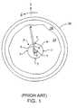
- vectorsare created by directing focused ultrasonic pressure waves 2 radially from a transducer in a catheter and collecting echoes 4 at the same transducer from the target area, as seen in Fig. 1.
- the transduceris mechanically rotated at a uniform speed with multiple firings of ultrasonic excitation in order to obtain a plurality of equally spaced radial vectors from the collected echoes.
- the plurality of radial vectors from the rotated transducercomprises an image frame.
- a signal processorthen performs image processing (e.g., stabilization of a moving image, temporal filtering for blood speckle, and other image enhancement techniques) on the acquired data in order to provide a display of the corrected and filtered intravascular image on a raster-scan display monitor.
- image processinge.g., stabilization of a moving image, temporal filtering for blood speckle, and other image enhancement techniques
- Some conventional techniques used to detect non-uniform rotation of the transducer in intravascular ultrasound imaginginvolve calibrating the catheter 3 with landmarks or beacons 7, whether active or passive, generally located at various points (circumferentially or helically) along the perimeter of sheath 9 of the catheter 3, as seen in Fig. 1.
- Each beacon's position relative to the catheteris known.
- Passive beaconsact as reflectors of ultrasound transmitted by the catheter and may undesirably cause reflective bright spots on the image which shadow points in the intravascular field behind the spots.
- Active beaconstransmit ultrasonic energy (characterized by phase, amplitude, frequency and/or pulse repetition rate so as to identify the particular beacon) in the direction of the rotating transducer so that the imaging system may identify the particular beacon in order to determine the angular position of the transducer.
- ultrasonic energycharacterized by phase, amplitude, frequency and/or pulse repetition rate so as to identify the particular beacon
- the imaging systemmay identify the particular beacon in order to determine the angular position of the transducer.
- passive or active beaconsare not always effective because the beacons may cause shadowing of tissue behind the beacons or may introduce artifacts adversely affecting the imaging of the anatomical structures.
- US-A- 5,485,845describes an ultrasound system with includes an array of beacons that direct ultrasonic energy towards an imaging transducer.
- the individual beaconsare identifiable to determine the angular position of the imaging transducer.
- the present inventionprovides apparatus which detect non-uniform rotation in an improved manner without using beacons which may create shadowing of tissue behind the beacons or other undesired artifacts in the image.
- the present inventionmay provide a particularly simple and useful solution for addressing the problem of non-uniform rotation distortion in intravascular ultrasound imaging in systems which use mechanical scanning.
- the present inventionprovides apparatus for detecting non-uniform rotation distortion in an intravascular ultrasound blood vessel image as defined in claim 1.
- the apparatuscomprises a catheter probe within a blood vessel, where the catheter probe includes a sheath and a transducer mechanically rotated within the catheter.
- the catheter probealso includes a bubbly liquid between the sheath and the transducer.
- Said transduceremits an ultrasonic beam to produce echoes reflected from the bubbly liquid and the sheath to obtain a given image vector.
- the echoesmay be sampled in multiple time windows for the given image vector.
- the sampled echoesmay be correlated in the multiple time windows to determine existence of non-uniform rotational speed of the transducer.
- the present inventionprovides apparatus for detecting non-uniform rotation distortion in an intravascular ultrasound blood vessel image as defined in claim 5.
- the catheter probe within a blood vesselwhere the catheter probe has a transducer apparatus comprises located therein and the transducer is mechanically controlled.
- Multiple ultrasonic beamsare emitted to produce echoes reflected from a blood region within the blood vessel to obtain multiple successive image vectors, and the echoes are sampled at a predetermined range (r P ) for each of the successive image vectors.
- the r P for each of the successive image vectorsis located within the blood region. Correlation coefficients are obtained for the sampled echoes at r P between each of the successive image vectors to determine changes in a rotational speed of the transducer.
- the present inventionprovides for detection of non-uniform rotation distortion for enhanced image processing in intravascular ultrasound imaging systems.
- the present inventionprovides image processing apparatus which may be used to detect non-uniform rotation distortion in the displayed image with the intravascular ultrasonic imaging system (shown in Fig. 2) which uses mechanical scanning without active or passive beacons.
- FIG. 2there is shown a block diagram of a type of intravascular ultrasonic imaging system 10 that may be used for intravascular image display in accordance with a specific embodiment of the present invention.
- Fig. 3illustrates a cross-sectional view of a blood vessel and a catheter probe therein of an IVUS system utilizing mechanical scanning in accordance with the present invention.
- a specialized signal processing device 10is used with an ultrasonic imaging system 12 including a catheter probe 13 wherein ultrasonic beams 14 are emitted by an ultrasonic transmitter or exciter 16 of transducer 22, which is at the distal end of catheter 13 and is coupled via drive shaft 5 to a motor (not shown) at the proximal end of catheter 13.
- the ultrasonic signals 14of, for example, 5 Megahertz (MHz) to 50 MHz, are directed to an intravascular target to cause reflections in the form of ultrasonic echo signals 18 from the intravascular structures, including blood.
- Radial spokes or vectors 18 of informationare collected from a target 20 (the interior walls of a blood vessel) based on ultrasonic reflections received at a transducer 22.
- informationis gathered by projecting narrow ultrasonic sampling beams 14 (of a predetermined beamwidth) from exciter 16 as it is rotated (by an angle ⁇ ) within catheter 13 in blood vessel 20.
- the reflectionsscale in amplitude over a range and are recorded by transducer 22 as a function of unit distance (r) along the radius of each vector.
- the imageis representative of a cross-sectional "slice" of the structure of blood vessel 20 and includes wall structures (blood-wall interface) 26 and lumens of blood (blood region) 24, as seen in Figs. 2 and 3.
- This image datamay be acquired as either analog or digital information, depending on the specific system utilized.
- the data acquiredis converted into pixels representing points in a scanned (swept or rotated) two-dimensional image. These pixels are assigned a value on, for example, a gray scale between black and white. Of course, the assigned value may be on a color scale in other embodiments.
- signal processor 10After the intravascular ultrasonic imaging system acquires the image data, signal processor 10 performs signal processing of the acquired image data and scan-converting the image data into x-y rasterized image data for storing into display memory 32 and then providing the raster image for viewing on a display device 30 coupled to signal processor 10.
- Signal processor 10also includes a program memory 38 which may be used to store the computer-readable program(s) for implementing specific embodiment(s) of the present invention, as discussed further below.
- the computer-readable program(s) for implementing specific embodiments of the present inventionmay be stored on a memory coupled to signal processor 10.
- the memorymay be a read-only memory, fixed disk drive, or removable disk drive.
- transducer 22is mechanically rotated within sheath 9 of catheter 13 at a uniform speed of, for example, about 1800 revolutions per minute with about 300 firings of ultrasonic excitation in order to obtain a plurality of equally spaced radial vectors from the collected echoes for an image frame.
- Intravascular image framesare obtained by sampling reflections received at transducer 22 for r > r s , where r s is the distance between transducer 22 and sheath 9 of catheter 13.
- catheter 13is flushed with bubbly liquid containing, for example, micro-bubbles, as seen in Fig. 4.
- Fig. 4is a cross-sectional detailed view of a catheter probe with a bubbly liquid contained therein, according to this specific embodiment of the present invention.
- sheath 9is as non-reflective (i.e., as transmissive) of ultrasounds as possible so that ultrasounds may be emitted through sheath 9 and echoes may be received through sheath 9 for imaging purposes.
- at least some portion of sheath 9is reflective of ultrasound to provide the ultrasound reverberation utilized in the present embodiment.
- a first portion along the length of sheath 9 that is ultrasound transmissivemay be used for imaging purposes while a second portion along the length of sheath 9 that is ultrasound reflective may be used for non-uniform rotation purposes.
- liquid 40 which contains micro-bubbles 42By flushing catheter 13 with liquid 40 which contains micro-bubbles 42, a reverberation of ultrasound is created between transducer 22 and sheath 9.
- AlbunexTM available from Molecular Bioscience Inc. or TaligentTM available from Alliance Pharmaceuticalare exemplary bubbly liquids which may be used in the present invention as a contrast agent.
- Micro-bubbles 42 useful with the present embodimenthave a mean diameter on the order of about 4 ⁇ m or less with a distribution ranging between about 1-10 ⁇ m. Transducer 22 thus receives multiple echoes from sheath 9 and micro-bubbles 42 arising from different round trips of the ultrasonic beam echoed within sheath 9.
- Figs. 5(a) and 5(b)are exemplary diagrams of the amplitude of these multiple echoes received at transducer 22 in relation to time corresponding to distance r ⁇ r S when transducer 22 has uniform rotation and non-uniform rotation, respectively.
- equally spaced segments (amplitude in the time/depth dimension) along an imaging vector within r Swould be correlated with one another. Since the deeper segments of the imaging vector came from multiple round trips of ultrasound between transducer 22 and sheath 9, the correlation or the lack thereof in the different segments of the received signal is a measure of the rotational speed.
- the correlation between two segments of the imaging vector arising from different round trips between transducer and the sheathwould be high.
- equally spaced segments in the image vectorare shown as windows (w 1 , w 2 , w 3 , and w 4 ) in time.
- Each time windowshould be as short as possible but have a sufficient width (i.e.g, time duration) to capture enough information from an echo in order to perform an adequate correlation.
- Fig. 5(a)correlating each of the segments of the image vector with the preceding segment results in correlation coefficients of about 0.72, 0.71 and 0.73 for w 2 , w 3 , and w 4 , respectively.
- the highly correlated segmentsindicate that transducer 22 is rotating in a substantially uniform manner. Any rotational non-uniformity of transducer 22 would manifest itself as a notable change in the correlation coefficient in segments of the imaging vector. In particular, an increase in the correlation coefficient from window to successive window would indicate that the transducer's rotational motion has slowed down, and a decrease in the correlation coefficient from window to successive window would indicate that the transducer's rotational motion has sped up. In the example of Fig.
- the present embodimentis suitable for use with catheters where the distance r s between sheath 9 and transducer 22 is large enough to provide for close ultrasound reverberations with each window being sufficiently wide so as to capture only one reverberation.
- a catheter having a transducer small in size compared to the sheathwhich would have dimensions as required for the particular intravascular application, may be useful for the present embodiment.
- correlation over larger time separationcan also be performed across different segments in different imaging vectors. If transducer 22 is rotating with uniform speed, the correlation coefficient will remain the same for a given separation in time and beamwidth. Multiple correlation coefficients for a given time separation can be made and the average can be used to improve the accuracy of the measurement, in other embodiments.
- the present inventionuses correlation of blood speckle to track the rotation of the transducer.
- This embodimentcould utilize the general correlation expression given in equation 6 or 11 of the Barnea reference, in the 1-dimensional time/depth domain for a given depth ( ⁇ P ) in successive image vectors.
- a region 50 in the imaging scene where the image texture is full of speckleis selected.
- the correlation coefficientshould be low for respective points ⁇ P (in successive image vectors) that are separated from each other by greater than the ultrasound beamwidth (measured in angle); whereas, within blood speckle region 50, the correlation coefficient should be high for respective points ⁇ P (in successive image vectors) that are separated from each other by less than the ultrasound beamwidth.
- FIG. 6(a)is an exemplary diagram illustrating successive vectors for a transducer 22 rotating uniformly, according to this specific embodiment.
- the transducer 22is located substantially in the center of blood vessel 20, but it should be recognized that the discussion also applies when transducer 22 is off-center as long as region 50 of blood speckle exists for use with the present embodiment.
- transducer 22is rotating with a uniform rotational speed ⁇ with successive image vectors (specifically, image vector 52 taken for ⁇ i , image vector 54 taken for ⁇ i+1 , and image vector 56 taken for ⁇ i+2 ) being uniformly separated by a uniform angular separation ⁇ .
- the correlation between each successive image vector (between 52 and 54, and between 54 and 56) at the same predetermined range r Pshould be relatively high and substantially similar between successive image vectors which maintain about the same angular separation.
- the lack of fluctuation of the correlation coefficient in successive imaging vectorsindicates a lack of fluctuation (i.e., uniform rotation) in the rotational speed of transducer 21.
- Figs. 6(b)-6(c)are exemplary diagrams illustrating successive vectors for a non-uniformly rotating transducer which is increasing and decreasing, respectively, in rotational speed in comparison to the uniform rotational speed shown in Fig. 6(a).
- transducer 22rotates with a uniform rotational speed ⁇ from image vector 52 taken for ⁇ i to image vector 54 taken for ⁇ i+1 , which are uniformly separated by a uniform angular separation ⁇ .
- transducer 22starts to rotate with an increasing rotational speed ⁇ + ⁇ 1 from image vector 54 taken for ⁇ i+1 to image vector 62 taken for ⁇ i+2 .
- the correlation between successive image vectors 52 and 54 at the same predetermined range r Pshould be relatively high and is defined by C ⁇ .
- the correlation between successive image vectors 54 and 62 at the same predetermined range r Pshould be lower than the correlation C ⁇ between vectors 52 and 54, since successive image vectors 54 and 62 have a wider angular separation compared to the beamwidth.
- the decrease of the correlation coefficient from C ⁇ in successive imaging vectorsindicates an increase in the rotational speed of transducer 21.
- transducer 22rotates with a uniform rotational speed ⁇ from image vector 52 taken for ⁇ i to image vector 54 taken for ⁇ i+1 , which are uniformly separated by a uniform angular separation ⁇ .
- transducer 22starts to rotate with a decreasing rotational speed ⁇ - ⁇ 2 from image vector 54 taken for ⁇ i+1 to image vector 64 taken for ⁇ i+2 .
- the correlation between successive image vectors 52 and 54 at the same predetermined range r Pshould be relatively high and is defined by C ⁇ .
- the correlation between successive image vectors 54 and 64 at the same predetermined range r Pshould be higher than the correlation C ⁇ between vectors 52 and 54, since successive image vectors 54 and 64 have an even smaller angular separation compared to the beamwidth than image vectors 52 and 54.
- the increase of the correlation coefficient from C ⁇ in successive imaging vectorsindicates a decrease in the rotational speed of transducer 21.
- correlation of blood speckleis used to track the rotation of the transducer.
- These embodimentsalso could utilize the general correlation expression given in equation 6 or 11 of the Barnea reference, in the 1-dimensional time/depth domain for multiple given ranges or depths (r P1 , r P2 , r P3 , etc.) in successive image vectors, in order to provide various measurements of the non-uniform rotation for greater accuracy of detection.
- the present embodimentsdescribed in relation to Figs.
- Fig. 7(a)is an exemplary diagram illustrating successive vectors for a transducer 22 rotating uniformly, according to the present specific embodiment.
- Figs. 7(b)-7(c)are exemplary diagrams illustrating successive vectors for a non-uniformly rotating transducer which is increasing and decreasing, respectively, in rotational speed in comparison to the uniform rotational speed shown in Fig. 7(a).
- the transducer 22is located substantially in the center of blood vessel 20, but it should be recognized that the discussion also applies when transducer 22 is off-center as long as region 50 of blood speckle exists for use with the present embodiment. As seen in Fig.
- transducer 22is rotating with a uniform rotational speed ⁇ with successive image vectors (specifically, image vector 72 taken for ⁇ i , image vector 74 taken for ⁇ i+1 , and image vector 56 taken for ⁇ i+2 ) being uniformly separated by a uniform angular separation ⁇ .
- the correlations between each successive image vector (between 52 and 54, and between 54 and 56) at the same predetermined ranges r P1 and r P2should be relatively high and substantially similar between successive image vectors which maintain about the same angular separation.
- the lack of fluctuation of the correlation coefficient in successive imaging vectorsindicates a lack of fluctuation (i.e., uniform rotation) in the rotational speed of transducer 22.
- the correlation coefficient at a particular range between successive image vectorsshould be low for values of the range that have a separation greater than the ultrasound beamwidth.
- the correlation coefficient at a particular range between successive image vectorsshould be high for values of the range that have a separation less than the ultrasound beamwidth. Determining the correlation coefficients at more than one range value between successive image vectors enables greater accuracy of the detection of non-uniform rotation.
- the correlation coefficients at both r P1 and r P2 between successive vectorsshould be substantially the same when the successive vectors maintain about the same angular separation (i.e., uniform rotation of transducer 21).
- transducer 22rotates with a uniform rotational speed ⁇ from image vector 72 taken for ⁇ i to image vector 74 taken for ⁇ i+1 , which are uniformly separated by a uniform angular separation ⁇ . However, transducer 22 starts to rotate with an increasing rotational speed ⁇ + ⁇ 1 from image vector 74 taken for ⁇ i+1 to image vector 82 taken for ⁇ i+2 .
- the correlations between successive image vectors 74 and 82 at the predetermined ranges ⁇ P1 and ⁇ P2should both be lower than the correlations C ⁇ 1 and C ⁇ 2 between vectors 72 and 74, since successive image vectors 74 and 82 have a wider angular separation compared to the beamwidth.
- the decrease of the correlation coefficients from C ⁇ 1 and C ⁇ 2 in successive imaging vectors 74 and 82indicates an increase in the rotational speed of transducer 22.
- transducer 22rotates with a uniform rotational speed ⁇ from image vector 72 taken for ⁇ i to image vector 74 taken for ⁇ i+1 , which are uniformly separated by a uniform angular separation ⁇ .
- transducer 22starts to rotate with a decreasing rotational speed ⁇ - ⁇ 2 from image vector 74 taken for ⁇ i+1 to image vector 84 taken for ⁇ i+2 .
- the correlation between successive image vectors 72 and 74 at the same predetermined ranges ⁇ P1 and ⁇ P2should be relatively high and are defined as C ⁇ 1 and C ⁇ 2 , respectively.
- the correlations between successive image vectors 74 and 84 at the same predetermined ranges ⁇ P1 and ⁇ P2should be higher than the correlations C ⁇ 1 and C ⁇ 2 between vectors 72 and 74, since successive image vectors 74 and 84 have an even smaller angular separation compared to the beamwidth than image vectors 72 and 74.
- the increase of the correlation coefficients from C ⁇ 1 and C ⁇ 2 in successive imaging vectors 74 and 84indicates a decrease in the rotational speed of transducer 21.
- the value of the correlation at ⁇ P1 and the value of the correlation at ⁇ P2may be averaged if the values differ (the difference in values being attributed to noise).
- the correlation coefficient between successive vectors at ⁇ P1will typically have the same percentage change as the correlation coefficient between successive vectors at ⁇ P2 , because the distance between points at ⁇ P2 in successive vectors is less than the beamwidth at ⁇ P2 by a greater amount than the distance between points at ⁇ P1 in successive vectors is less than the beamwidth at ⁇ P1 .
- transducer 22rotates with a uniform rotational speed ⁇ from image vector 72 taken for ⁇ i to image vector 74 taken for ⁇ i+1 , which are uniformly separated by a uniform angular separation ⁇ .
- transducer 22starts to rotate with an increasing rotational speed ⁇ + ⁇ 1 from image vector 74 taken for ⁇ i+1 to image vector 82 taken for ⁇ i+2 .
- the correlations between successive image vectors 74 and 82 at the predetermined ranges r P1 and r P2should both be lower by a similar percentage than the correlations C ⁇ 1 and C ⁇ 2 between vectors 72 and 74, since successive image vectors 74 and 82 at r P2 have a narrower angular separation compared to the increased beamwidth at r P2 and successive image vectors 74 and 82 at r P1 have a wider angular separation compared to the decreased beamwidth at r P1 .
- transducer 22rotates with a uniform rotational speed ⁇ from image vector 72 taken for ⁇ i to image vector 74 taken for ⁇ i+1 , which are uniformly separated by a uniform angular separation ⁇ .
- transducer 22starts to rotate with a decreasing rotational speed ⁇ - ⁇ 2 from image vector 74 taken for ⁇ i+1 to image vector 84 taken for ⁇ i+2 .
- the correlation between successive image vectors 72 and 74 at the same predetermined ranges r P1 and r P2should be relatively high and are defined as C ⁇ 1 and C ⁇ 2 , respectively.
- the correlations between successive image vectors 74 and 84 at the same predetermined ranges r P1 and r P2e.g., the correlation at r P1 between vectors 74 and 82 is about 0.88, and the correlation at r P2 between vectors 74 and 82 is about 0.99
- the increase of the correlation coefficients from C ⁇ 1 and C ⁇ 2 in successive imaging vectors 74 and 84indicates a decrease in the rotational speed of transducer 21.
- r Pis preferably selected such that it lies beyond the far-field of the transducer.
Landscapes
- Health & Medical Sciences (AREA)
- Life Sciences & Earth Sciences (AREA)
- Engineering & Computer Science (AREA)
- Physics & Mathematics (AREA)
- Remote Sensing (AREA)
- Radar, Positioning & Navigation (AREA)
- Molecular Biology (AREA)
- General Health & Medical Sciences (AREA)
- Pathology (AREA)
- Biomedical Technology (AREA)
- Heart & Thoracic Surgery (AREA)
- Medical Informatics (AREA)
- Nuclear Medicine, Radiotherapy & Molecular Imaging (AREA)
- Surgery (AREA)
- Animal Behavior & Ethology (AREA)
- Radiology & Medical Imaging (AREA)
- Public Health (AREA)
- Veterinary Medicine (AREA)
- Biophysics (AREA)
- Acoustics & Sound (AREA)
- Computer Networks & Wireless Communication (AREA)
- General Physics & Mathematics (AREA)
- Hematology (AREA)
- Ultra Sonic Daignosis Equipment (AREA)
Description
- The present invention relates to high resolution intravascular imaging andmore particularly to intravascular ultrasound imaging and techniques for enhancing imagequality .
- In intraluminal or intravascular ultrasound (also referred to as "IVUS")imaging, the production of high resolution images of vessel wall structures requiresimaging at high ultrasound frequencies. IVUS imaging systems may utilize electronicscanners or mechanical scanners. IVUS systems utilizing electronic scanning typicallyinclude in the distal end of a catheter an array of ultrasound transducers which aresequentially excited so as to electronically scan an ultrasonic beam. IVUS systemsutilizing mechanical scanning (one example of such a system being shown in Fig. 1) mayuse a single
rotating transducer 1 in the distal end of acatheter 3 that enters thebloodvessel 20, with adrive shaft 5 coupling thetransducer 1 to a motor (not shown) coupledto thecatheter 3 at its proximal end. IVUS systems using mechanical scanning havewider applications, mainly due to the smaller size of the mechanical scanner incomparison with electronic scanner, that advantageously allow the system to be used forsmaller blood vessels as well as larger blood vessels. - The present invention relates to IVUS imaging systems with mechanicalscanning. In these types of IVUS systems, an ultrasonic unidirectional exciter/detector(e.g., transducer) within a catheter probe positioned within a blood vessel is used toacquire signal data from echoes of the emitted ultrasonic energy off the interior of theblood vessel. Specifically, vectors are created by directing focused
ultrasonic pressurewaves 2 radially from a transducer in a catheter and collectingechoes 4 at the sametransducer from the target area, as seen in Fig. 1. In an exemplary IVUS system withmechanical scanning, the transducer is mechanically rotated at a uniform speed with multiple firings of ultrasonic excitation in order to obtain a plurality of equally spacedradial vectors from the collected echoes. The plurality of radial vectors from the rotatedtransducer comprises an image frame. A signal processor then performs imageprocessing (e.g., stabilization of a moving image, temporal filtering for blood speckle,and other image enhancement techniques) on the acquired data in order to provide adisplay of the corrected and filtered intravascular image on a raster-scan display monitor.Signal processing in an intravascular ultrasound imaging system utilizing a mechanicallyrotated transducer operates under the assumption that the transducer is rotated at auniform speed. However, this assumption is often violated as the catheter traverses theblood vessel. Specifically, the friction between the catheter and the vessel walls and/orthe flexing of the vessel walls causes binding and/or whipping of the catheter, whichtranslates into non-uniform rotation of the transducer. The system thus inaccurately readsthe reflected echoes from blood/vessel structure/blood vessel as being received from anincorrect location, as the assumption of uniform rotational speed is violated. Therefore,it is desirable to detect and quantize the non-uniform rotation in order to correct for theimage distortion caused by non-uniform rotation, and thereby provide an intravascularimage display with enhanced accuracy. - Some conventional techniques used to detect non-uniform rotation of thetransducer in intravascular ultrasound imaging involve calibrating the
catheter 3 withlandmarks orbeacons 7, whether active or passive, generally located at various points(circumferentially or helically) along the perimeter ofsheath 9 of thecatheter 3, as seenin Fig. 1. Each beacon's position relative to the catheter is known. Passive beacons actas reflectors of ultrasound transmitted by the catheter and may undesirably causereflective bright spots on the image which shadow points in the intravascular field behindthe spots. Active beacons transmit ultrasonic energy (characterized by phase, amplitude,frequency and/or pulse repetition rate so as to identify the particular beacon) in thedirection of the rotating transducer so that the imaging system may identify the particularbeacon in order to determine the angular position of the transducer. However, suchconventional techniques using passive or active beacons are not always effective becausethe beacons may cause shadowing of tissue behind the beacons or may introduce artifactsadversely affecting the imaging of the anatomical structures. - US-A- 5,485,845 describes an ultrasound systemwith includes an array of beacons that direct ultrasonicenergy towards an imaging transducer. Theindividual beacons are identifiable to determine the angularposition of the imaging transducer.
- From the above, it can be seen that alternative methods and apparatus areneeded for detecting non-uniform rotation distortion to allow enhanced display ofintravascular ultrasound images.
- The present invention provides apparatus which detect non-uniformrotation in an improved manner without using beacons which may createshadowing of tissue behind the beacons or other undesired artifacts in the image. Inspecific embodiments, the present invention may provide a particularly simple and usefulsolution for addressing the problem of non-uniform rotation distortion in intravascularultrasound imaging in systems which use mechanical scanning.
- According to a specific embodiment, the present invention provides apparatusfor detecting non-uniform rotation distortion in an intravascular ultrasound bloodvessel image as defined in
claim 1. The apparatus comprises a catheter probe within a bloodvessel, where the catheter probe includes a sheath and a transducer mechanicallyrotated within the catheter. The catheterprobe also includes a bubbly liquid between the sheath and the transducer.Said transducer emits an ultrasonic beam to produce echoes reflected fromthe bubbly liquid and the sheath to obtain a given image vector. The echoes may besampled in multiple time windows for the given image vector.The sampled echoes may be correlated in the multiple time windows to determineexistence of non-uniform rotational speed of the transducer. - According to another specific embodiment, the present invention provides apparatusfor detecting non-uniform rotation distortion in an intravascular ultrasound bloodvessel image as defined in
claim 5. The catheter probe within a blood vessel, where thecatheter probe has a transducer apparatus comprises located therein and the transduceris mechanically controlled. Multipleultrasonic beams are emitted to produce echoes reflected from a blood region within the blood vesselto obtain multiple successive image vectors, and the echoes are sampled at a predeterminedrange (rP) for each of the successive image vectors. The rP for each of the successiveimage vectors is located within the blood region.Correlation coefficients are obtained for the sampled echoes at rP between each of the successiveimage vectors to determine changes in a rotational speed of the transducer. - Theseembodiments, as well as their advantages and features, aredescribed in more detail in conjunction with the text below and attached figures.
- Fig. 1 is a cross-sectional view of a blood vessel and a catheter probetherein of an exemplary IVUS system utilizing mechanical scanning, in accordance withthe prior art;
- Fig. 2 is a block diagram of an intravascular ultrasonic imaging system inaccordance with a specific embodiment of the present invention;
- Fig. 3 is a cross-sectional view of a blood vessel and a catheter probetherein of an IVUS system utilizing mechanical scanning, in accordance with the presentinvention;
- Fig. 4 is a cross-sectional detailed view of a catheter probe with a bubblyliquid contained therein, according to a specific embodiment of the present invention;
- Figs. 5(a) and 5(b) are exemplary diagrams of the amplitude of multipleechoes received at
transducer 22 in relation with time corresponding to distance r < rSwhentransducer 22 has uniform rotation and non-uniform rotation, respectively, inaccordance with the specific embodiment of Fig. 4; - Fig. 6(a) is an exemplary diagram illustrating successive vectors for atransducer rotating uniformly, according to another specific embodiment of the presentinvention;
- Figs. 6(b)-6(c) are exemplary diagrams illustrating successive vectors for anon-uniformly rotating transducer which is increasing and decreasing, respectively, inrotational speed in comparison to the uniform rotational speed shown in Fig. 6(a).
- Fig. 7(a) is an exemplary diagram illustrating successive vectors for atransducer rotating uniformly, according to yet another specific embodiment of thepresent invention; and
- Figs. 7(b)-7(c) are exemplary diagrams illustrating successive vectors for anon-uniformly rotating transducer which is increasing and decreasing, respectively, inrotational speed in comparison to the uniform rotational speed shown in Fig. 7(a).
- The present invention provides for detection of non-uniform rotationdistortion for enhanced image processing in intravascular ultrasound imaging systems.The present invention provides image processing apparatus which may be used to detectnon-uniform rotation distortion in the displayed image with the intravascular ultrasonicimaging system (shown in Fig. 2) which uses mechanical scanning without active orpassive beacons.
- Referring to Fig. 2, there is shown a block diagram of a type ofintravascular
ultrasonic imaging system 10 that may be used for intravascular imagedisplay in accordance with a specific embodiment of the present invention. Fig. 3illustrates a cross-sectional view of a blood vessel and a catheter probe therein of anIVUS system utilizing mechanical scanning in accordance with the present invention. Asseen in Fig. 2, a specializedsignal processing device 10 is used with anultrasonicimaging system 12 including acatheter probe 13 whereinultrasonic beams 14 are emittedby an ultrasonic transmitter or exciter 16 oftransducer 22, which is at the distal end ofcatheter 13 and is coupled viadrive shaft 5 to a motor (not shown) at the proximal end ofcatheter 13. Theultrasonic signals 14 of, for example, 5 Megahertz (MHz) to 50 MHz,are directed to an intravascular target to cause reflections in the form ofultrasonic echosignals 18 from the intravascular structures, including blood. Radial spokes orvectors 18of information are collected from a target 20 (the interior walls of a blood vessel) basedon ultrasonic reflections received at atransducer 22. Specifically, information isgathered by projecting narrow ultrasonic sampling beams 14 (of a predeterminedbeamwidth) from exciter 16 as it is rotated (by an angle ) withincatheter 13 inbloodvessel 20. The reflections scale in amplitude over a range and are recorded bytransducer 22 as a function of unit distance (r) along the radius of each vector. Theimage is representative of a cross-sectional "slice" of the structure ofblood vessel 20 andincludes wall structures (blood-wall interface) 26 and lumens of blood (blood region) 24,as seen in Figs. 2 and 3. This image data may be acquired as either analog or digitalinformation, depending on the specific system utilized. The data acquired is convertedinto pixels representing points in a scanned (swept or rotated) two-dimensional image.These pixels are assigned a value on, for example, a gray scale between black and white.Of course, the assigned value may be on a color scale in other embodiments. After theintravascular ultrasonic imaging system acquires the image data,signal processor 10 performs signal processing of the acquired image data and scan-converting the image datainto x-y rasterized image data for storing intodisplay memory 32 and then providing theraster image for viewing on adisplay device 30 coupled to signalprocessor 10.Signalprocessor 10 also includes a program memory 38 which may be used to store thecomputer-readable program(s) for implementing specific embodiment(s) of the presentinvention, as discussed further below. Alternatively, the computer-readable program(s)for implementing specific embodiments of the present invention may be stored on amemory coupled to signalprocessor 10. For example, the memory may be a read-onlymemory, fixed disk drive, or removable disk drive. - In the IVUS system shown in Figs. 2 and 3,
transducer 22 is mechanicallyrotated withinsheath 9 ofcatheter 13 at a uniform speed of, for example, about 1800revolutions per minute with about 300 firings of ultrasonic excitation in order to obtain aplurality of equally spaced radial vectors from the collected echoes for an image frame.For each ultrasonic beam fired, the amplitude for a particular distance r in the radialvector is obtained by sampling the reflections received attransducer 22, where r = (tc)/2(where t is the time between the firing of the ultrasonic beam and the receipt of theparticular amplitude being sampled, and c is the speed of sound in the blood/tissue/watermedium, which may be about 1500 meters/second ± 20% variation depending, amongother factors, on the temperature and type of the medium). Intravascular image framesare obtained by sampling reflections received attransducer 22 for r > rs, where rs is thedistance betweentransducer 22 andsheath 9 ofcatheter 13. - According to a specific embodiment of the present invention,
catheter 13 isflushed with bubbly liquid containing, for example, micro-bubbles, as seen in Fig. 4.Fig. 4 is a cross-sectional detailed view of a catheter probe with a bubbly liquidcontained therein, according to this specific embodiment of the present invention. In thepresent embodiment,sheath 9 is as non-reflective (i.e., as transmissive) of ultrasounds aspossible so that ultrasounds may be emitted throughsheath 9 and echoes may be receivedthroughsheath 9 for imaging purposes. However, for purposes of non-uniform rotationdetection, at least some portion ofsheath 9 is reflective of ultrasound to provide theultrasound reverberation utilized in the present embodiment. For example, a first portionalong the length ofsheath 9 that is ultrasound transmissive may be used for imagingpurposes while a second portion along the length ofsheath 9 that is ultrasound reflectivemay be used for non-uniform rotation purposes. By flushingcatheter 13 with liquid 40 which contains micro-bubbles 42, a reverberation of ultrasound is created betweentransducer 22 andsheath 9. Albunex™ available from Molecular Bioscience Inc. orTaligent™ available from Alliance Pharmaceutical are exemplary bubbly liquids whichmay be used in the present invention as a contrast agent. Micro-bubbles 42 useful withthe present embodiment have a mean diameter on the order of about 4 µm or less with adistribution ranging between about 1-10 µm.Transducer 22 thus receives multipleechoes fromsheath 9 andmicro-bubbles 42 arising from different round trips of theultrasonic beam echoed withinsheath 9. - In accordance with the present embodiment of Fig. 4, Figs. 5(a) and 5(b)are exemplary diagrams of the amplitude of these multiple echoes received at
transducer 22 in relation to time corresponding to distance r < rS whentransducer 22 has uniformrotation and non-uniform rotation, respectively. According to the present embodiment,equally spaced segments (amplitude in the time/depth dimension) along an imaging vectorwithin rS would be correlated with one another. Since the deeper segments of theimaging vector came from multiple round trips of ultrasound betweentransducer 22 andsheath 9, the correlation or the lack thereof in the different segments of the receivedsignal is a measure of the rotational speed. For a non-rotating environment, thecorrelation between two segments of the imaging vector arising from different round tripsbetween transducer and the sheath would be high. For example, as seen in Fig. 5(a),equally spaced segments in the image vector are shown as windows (w1, w2, w3, and w4)in time. The time to between the beginning of a window and the beginning of the nextsuccessive window is preferably greater than the time tS = (2 rS)/c between an ultrasonicbeam being emitted by the transducer and a first echo received by the transducer. Eachtime window should be as short as possible but have a sufficient width (i.e.g, timeduration) to capture enough information from an echo in order to perform an adequatecorrelation. In the example of Fig. 5(a), correlating each of the segments of the imagevector with the preceding segment results in correlation coefficients of about 0.72, 0.71and 0.73 for w2, w3, and w4, respectively. Thus, the highly correlated segments indicatethattransducer 22 is rotating in a substantially uniform manner. Any rotational non-uniformityoftransducer 22 would manifest itself as a notable change in the correlationcoefficient in segments of the imaging vector. In particular, an increase in thecorrelation coefficient from window to successive window would indicate that thetransducer's rotational motion has slowed down, and a decrease in the correlation coefficient from window to successive window would indicate that the transducer'srotational motion has sped up. In the example of Fig. 5(b), correlating each of thesesegments of the image vector with the successive segment results in correlationcoefficients of about 0.73, 0.53 and 0.91 for w2, w3, and w4, respectively. As seen inFig. 5(a)-5(b), non-uniform rotation, more specifically, an increase in the transducer'srotational speed, has occurred from window w3 to w2; while non-uniform rotation, morespecifically, a decrease in the transducer's rotational speed, has occurred from windoww4 to w3. The present embodiment is suitable for use with catheters where the distance rsbetweensheath 9 andtransducer 22 is large enough to provide for close ultrasoundreverberations with each window being sufficiently wide so as to capture only onereverberation. For example, a catheter having a transducer small in size compared to thesheath, which would have dimensions as required for the particular intravascularapplication, may be useful for the present embodiment. - In accordance with other specific embodiments using a liquid-flushed
catheter 13 with the liquid being filled with micro-bubbles, correlation over larger timeseparation can also be performed across different segments in different imaging vectors.Iftransducer 22 is rotating with uniform speed, the correlation coefficient will remain thesame for a given separation in time and beamwidth. Multiple correlation coefficients fora given time separation can be made and the average can be used to improve theaccuracy of the measurement, in other embodiments. - Examples of correlation techniques which may be used in accordance withthe present invention are discussed in detail by Daniel I. Barnea and Harvey F. Silvermanin an article entitled "A Class of Algorithms for Fast Digital Image Registration," onpages 179-186 of theIEEE Transactions on Computers, Vol. C-21, No. 2, February1972, and by Petros Maragos in an article entitled "Morphological Correlation and MeanAbsolute Error Criteria," on pages 1568-1571 of theIEEE Proceedings 1989 of theInternational Conference on Acoustic Speech and Signal Processing.For example, the specificembodiments discussed above (for example, the embodiments relating to Fig. 4) couldutilize the general correlation expression given in equation 6 or 11 of the Barneareference, but in the 1-dimensional time/depth domain.
- According to another specific embodiment, the present invention usescorrelation of blood speckle to track the rotation of the transducer. This embodiment could utilize the general correlation expression given in equation 6 or 11 of the Barneareference, in the 1-dimensional time/depth domain for a given depth (ΓP) in successiveimage vectors. According to this embodiment, a
region 50 in the imaging scene wherethe image texture is full of speckle is selected. Withinblood speckle region 50, thecorrelation coefficient should be low for respective points ΓP (in successive image vectors)that are separated from each other by greater than the ultrasound beamwidth (measured inangle); whereas, withinblood speckle region 50, the correlation coefficient should behigh for respective points ΓP (in successive image vectors) that are separated from eachother by less than the ultrasound beamwidth. Fig. 6(a) is an exemplary diagramillustrating successive vectors for atransducer 22 rotating uniformly, according to thisspecific embodiment. For simplicity, thetransducer 22 is located substantially in thecenter ofblood vessel 20, but it should be recognized that the discussion also applieswhentransducer 22 is off-center as long asregion 50 of blood speckle exists for use withthe present embodiment. As seen in Fig. 6(a),transducer 22 is rotating with a uniformrotational speed ω with successive image vectors (specifically,image vector 52 taken fori,image vector 54 taken for i+1, andimage vector 56 taken for i+2) being uniformlyseparated by a uniform angular separation Δ. The correlation between each successiveimage vector (between 52 and 54, and between 54 and 56) at the same predeterminedrange rP (we define this correlation for uniformly rotating speed ω to be Cω) should berelatively high and substantially similar between successive image vectors whichmaintain about the same angular separation. The lack of fluctuation of the correlationcoefficient in successive imaging vectors indicates a lack of fluctuation (i.e., uniformrotation) in the rotational speed of transducer 21. - Figs. 6(b)-6(c) are exemplary diagrams illustrating successive vectors for anon-uniformly rotating transducer which is increasing and decreasing, respectively, inrotational speed in comparison to the uniform rotational speed shown in Fig. 6(a). Asseen in Fig. 6(b),
transducer 22 rotates with a uniform rotational speed ω fromimagevector 52 taken for i to imagevector 54 taken for i+1, which are uniformly separatedby a uniform angular separation Δ. However,transducer 22 starts to rotate with anincreasing rotational speed ω + Δω1 fromimage vector 54 taken for i+1 to imagevector 62 taken for i+2. The correlation betweensuccessive image vectors successive image vectors vectors successive image vectors - In Fig. 6(c),
transducer 22 rotates with a uniform rotational speed ω fromimage vector 52 taken for i to imagevector 54 taken for i+1, which are uniformlyseparated by a uniform angular separation Δ. However,transducer 22 starts to rotatewith a decreasing rotational speed ω - Δω2 fromimage vector 54 taken for i+1 to imagevector 64 taken for i+2. Again, the correlation betweensuccessive image vectors successive image vectors vectors successive image vectors image vectors - According to further specific embodiments which are similar to theembodiment discussed above for Figs. 6(a)-6(c), correlation of blood speckle is used totrack the rotation of the transducer. These embodiments also could utilize the generalcorrelation expression given in equation 6 or 11 of the Barnea reference, in the 1-dimensionaltime/depth domain for multiple given ranges or depths (rP1, rP2, rP3, etc.) insuccessive image vectors, in order to provide various measurements of the non-uniformrotation for greater accuracy of detection. The present embodiments, described inrelation to Figs. 7(a)-7(c), are herein discussed for two given depths (rP1 and rP2, whererP1 is closer to the transducer than rP2) merely for purposes of simplicity in explanation.In a similar manner as for the embodiment of Figs. 6(a)-6(c),
region 50 in the imagingscene where the image texture is full of speckle is selected for the embodiment of Figs.7(a)-7(c). - Fig. 7(a) is an exemplary diagram illustrating successive vectors for a
transducer 22 rotating uniformly, according to the present specific embodiment. Figs.7(b)-7(c) are exemplary diagrams illustrating successive vectors for a non-uniformlyrotating transducer which is increasing and decreasing, respectively, in rotational speed incomparison to the uniform rotational speed shown in Fig. 7(a). For simplicity, thetransducer 22 is located substantially in the center ofblood vessel 20, but it should berecognized that the discussion also applies whentransducer 22 is off-center as long asregion 50 of blood speckle exists for use with the present embodiment. As seen in Fig.7(a),transducer 22 is rotating with a uniform rotational speed ω with successive imagevectors (specifically,image vector 72 taken for i,image vector 74 taken for i+1, andimage vector 56 taken for i+2) being uniformly separated by a uniform angularseparation Δ. The correlations between each successive image vector (between 52 and54, and between 54 and 56) at the same predetermined ranges rP1 and rP2 (we define thecorrelation at rP1 between successive image vectors for uniformly rotating speed ω to beCω1, and the correlation at rP2 between successive image vectors for uniformly rotatingspeed ω to be Cω2) should be relatively high and substantially similar between successiveimage vectors which maintain about the same angular separation. The lack of fluctuationof the correlation coefficient in successive imaging vectors indicates a lack of fluctuation(i.e., uniform rotation) in the rotational speed oftransducer 22. - Within
region 50, the correlation coefficient at a particular range betweensuccessive image vectors should be low for values of the range that have a separationgreater than the ultrasound beamwidth. In contrast, inblood speckle region 50, thecorrelation coefficient at a particular range between successive image vectors should behigh for values of the range that have a separation less than the ultrasound beamwidth.Determining the correlation coefficients at more than one range value between successiveimage vectors enables greater accuracy of the detection of non-uniform rotation. - If the beamwidth measured in angle remains constant at each of theselected ranges rP1 and rP2 in the beam falling within
region 50, then the correlationcoefficients at both rP1 and rP2 between successive vectors should be substantially thesame when the successive vectors maintain about the same angular separation (i.e.,uniform rotation of transducer 21). For example, the correlation coefficients betweensuccessive vectors successive vectors transducer 22rotates with a uniform rotational speed ω fromimage vector 72 taken for i to imagevector 74 taken for i+1, which are uniformly separated by a uniform angular separationΔ. However,transducer 22 starts to rotate with an increasing rotational speed ω + Δω1fromimage vector 74 taken for i+1 to imagevector 82 taken for i+2. However, the correlations betweensuccessive image vectors vectors vectors successive image vectors successive imaging vectors transducer 22. In Fig. 7(c),transducer 22 rotates with a uniform rotational speed ωfromimage vector 72 taken for i to imagevector 74 taken for i+1, which are uniformlyseparated by a uniform angular separation Δ. However,transducer 22 starts to rotatewith a decreasing rotational speed ω - Δω2 fromimage vector 74 taken for i+1 to imagevector 84 taken for i+2. Again, the correlation betweensuccessive image vectors successive imagevectors vectors vectors successive image vectors imagevectors successive imaging vectors vectors vectors - If the beamwidth measured in angle increases from the selected range ΓP1 toΓP2 in the beam falling within
region 50, then the correlation coefficient betweensuccessive vectors at ΓP1 will typically have the same percentage change as the correlationcoefficient between successive vectors at ΓP2, because the distance between points at ΓP2 insuccessive vectors is less than the beamwidth at ΓP2 by a greater amount than the distancebetween points at ΓP1 in successive vectors is less than the beamwidth at ΓP1. Forexample, the correlation coefficients betweensuccessive vectors successive vectors transducer 22 rotates with a uniform rotational speed ωfromimage vector 72 taken for i to imagevector 74 taken for i+1, which are uniformlyseparated by a uniform angular separation Δ. However,transducer 22 starts to rotatewith an increasing rotational speed ω + Δω1 fromimage vector 74 taken for i+1 toimagevector 82 taken for i+2. However, the correlations betweensuccessive imagevectors vectors vectors vectors successive image vectors successive image vectors successive imaging vectors transducer 22. In Fig. 7(c),transducer 22 rotates with a uniform rotational speed ωfromimage vector 72 taken for i to imagevector 74 taken for i+1, which are uniformlyseparated by a uniform angular separation Δ. However,transducer 22 starts to rotatewith a decreasing rotational speed ω - Δω2 fromimage vector 74 taken for i+1 to imagevector 84 taken for i+2. Again, the correlation betweensuccessive image vectors successive imagevectors vectors vectors vectors successive image vectors image vectors successive imaging vectors - In the embodiments discussed above for Figs. 6(a)-6(c) and for Figs. 7(a)-7(c),it should be recognized that the correlation between vectors would be governed bythe given beamwidth of the transducer. Since the beamwidth (measured in angle) of thetransducer may vary with r, rP is preferably selected such that it lies beyond the far-fieldof the transducer. The far-field of the transducer is determined by the expression
- Once non-uniform rotation is detected either by correlating echoes in aliquid-flushed catheter or by correlating blood speckle, conventionally known correctiveactions can include re-distribution of the imaging vectors, either in transmission ordisplay, in order to compensate for the non-uniform rotational speed and reduce orremove the distortion from the image.
Claims (13)
- Apparatus for detecting non-uniform rotation distortion in an intravascularultrasound blood vessel image, said apparatus comprising:a catheter (13) for use within a blood vessel, said catheter (13) including:wherein the bubbly liquid (40) is between said transducer (22) and said sheath(9) and said transducer (22) emits an ultrasonic beam (14) and receives echoes (18) ofsaid ultrasonic beam from micro-bubbles (42) in said bubbly liquid (40) and saidsheath (9); anda sheath (9),a bubbly liquid (40) within said catheter (13), anda transducer (22) mechanically rotated within said catheter (13),an image processor (12) capable of being coupled to said transducer (22), saidimage processor (12) including computer-readable program code fixed on tangiblecomputer-readable medium for storing said computer-readable program, saidcomputer-readable medium coupled to be read by said image processor, wherein saidcomputer-readable program code performs correlation on a plurality of segments (52,54, 56) in an image vector from said echoes (18) of said ultrasonic beam to detectnon-uniformity of rotation of said transducer (22).
- The apparatus of claim 1 wherein said bubbly liquid (40) includesmicrobubbles (42) having a diameter from about 1-10 µm.
- The apparatus of 1 wherein the plurality of segments (52, 54, 56) in an imagevector are shown as a plurality of windows (W1, W2, W3, W4) and the time tobetween the beginning of a window and the beginning of the next window is greaterthan the time ts = (2 rs)/c between said ultrasonic beam being emitted by saidtransducer and a first echo received by said transducer, where rs is the distancebetween the transducer and the sheath and c is the speed of sound in the bubbly liquid.
- The apparatus of claim 3 which is adapted to calculate a first correlationcoefficient between a first window and a second window and a second correlation coefficient between said second window and a third window, and which is adapted todetermine from a decrease in correlation coefficients that said rotational speed of saidtransducer (22) has increased and/or determine from an increase in correlationcoefficients that said rotational speed of said transducer (22) has decreased.
- Apparatus for detecting non-uniform rotation distortion in an intravascularultrasound blood vessel image, said apparatus comprising:a catheter (13) for use within a blood vessel, said catheter (13) including:wherein said transducer (22) emits a plurality of ultrasonic beams (14) toproduce echoes reflected from a blood region (50) within said blood vessel(20) to obtain a plurality of successive image vectors (72,74,76); anda sheath (9), anda transducer (22) mechanically rotated within said catheter (13),an image processor (12) capable of being coupled to said transducer (22), saidimage processor (12) including computer-readable program code fixed on tangiblecomputer-readable medium for storing said computer-readable program, saidcomputer-readable medium coupled to be read by said image processor, wherein saidcomputer-readable program code samples said echoes (18) at a predetermined range(rp) for each of said successive image vectors (72,74,76), wherein rp for each of saidsuccessive image vectors is located within said blood region (50), and wherein saidcomputer-readable program code also obtains correlation coefficients for said sampledechoes at rp between each of said successive image vectors to determine changes in arotational speed of said transducer (22).
- The apparatus of claim 5 wherein said computer-readable program codedetermines from a decrease in correlation coefficients that said rotational speed of saidtransducer (22) has increased and/or determines from an increase in correlationcoefficients that said rotational speed of said transducer has decreased.
- The apparatus of claim 5 or claim 6 wherein said predetermined range rP isselected to lie beyond the far-field of said transducer.
- The apparatus of any one of claims 5 to 7 wherein said computer-readableprogram code samples said echoes (18) at a plurality of predetermined ranges for eachof said successive image vectors (72,74,76), wherein said predetermined range ΓP isone of the plurality of predetermined ranges and a second predetermined range Γp2 isanother one of the plurality of predetermined ranges, wherein ΓP2 is selected to bewithin said blood region (50) at a greater distance from said transducer than said rP,and wherein said computer-readable program code also obtains correlation coefficientsfor said sampled echoes at Γp2.
- The apparatus of claim 8 wherein said predetermined range rp and said secondpredetermined range ΓP2 are each selected to lie beyond the far-field of said transducer.
- The apparatus of claim 8 or claim 9 wherein a beamwidth measured in angle ofsaid ultrasonic beams remains constant at each of the predetermined ranges ΓP and ΓP2.
- The apparatus of any one of claims 8 to 10 said computer-readable programcode determines that the correlation coefficients at both Γp and Γp2 are substantially thesame and thus that said successive vectors have maintained about the same angularseparation and hence the rotational speed of the transducer is unchanged.
- The apparatus of any one of claims 8 to 10 wherein said computer-readableprogram code determines from a decrease in correlation coefficients at both rP and rP2that said successive vectors have increased their angular separation and hence saidrotational speed of said transducer (22) has increased and/or determines from anincrease in correlation coefficients at both ΓP and ΓP2 that said successive vectors havedecreased their angular separation and hence said rotational speed of said transducerhas decreased.
- The apparatus of any one of claims 8 to 12 wherein a beamwidth measured inangle of said ultrasonic beams increases from said predetermined range rP to saidsecond predetermined range rP2.
Applications Claiming Priority (3)
| Application Number | Priority Date | Filing Date | Title |
|---|---|---|---|
| US977543 | 1997-11-25 | ||
| US08/977,543US5921934A (en) | 1997-11-25 | 1997-11-25 | Methods and apparatus for non-uniform rotation distortion detection in an intravascular ultrasound imaging system |
| PCT/IB1998/002126WO1999026541A1 (en) | 1997-11-25 | 1998-11-24 | Methods and apparatus for non-uniform rotation distorsion detection in an intravascular ultrasound imaging system |
Publications (3)
| Publication Number | Publication Date |
|---|---|
| EP1033937A1 EP1033937A1 (en) | 2000-09-13 |
| EP1033937A4 EP1033937A4 (en) | 2004-07-07 |
| EP1033937B1true EP1033937B1 (en) | 2005-08-31 |
Family
ID=25525252
Family Applications (1)
| Application Number | Title | Priority Date | Filing Date |
|---|---|---|---|
| EP98960057AExpired - LifetimeEP1033937B1 (en) | 1997-11-25 | 1998-11-24 | Methods and apparatus for non-uniform rotation distorsion detection in an intravascular ultrasound imaging system |
Country Status (8)
| Country | Link |
|---|---|
| US (3) | US5921934A (en) |
| EP (1) | EP1033937B1 (en) |
| JP (2) | JP4307711B2 (en) |
| AU (1) | AU1573699A (en) |
| CA (1) | CA2308505C (en) |
| DE (1) | DE69831418T2 (en) |
| ES (1) | ES2246544T3 (en) |
| WO (1) | WO1999026541A1 (en) |
Cited By (1)
| Publication number | Priority date | Publication date | Assignee | Title |
|---|---|---|---|---|
| US8206308B2 (en) | 2008-05-05 | 2012-06-26 | Boston Scientific Scimed, Inc. | Shielding for intravascular ultrasound imaging systems and methods of making and using |
Families Citing this family (126)
| Publication number | Priority date | Publication date | Assignee | Title |
|---|---|---|---|---|
| US6095976A (en)* | 1997-06-19 | 2000-08-01 | Medinol Ltd. | Method for enhancing an image derived from reflected ultrasound signals produced by an ultrasound transmitter and detector inserted in a bodily lumen |
| US6585763B1 (en) | 1997-10-14 | 2003-07-01 | Vascusense, Inc. | Implantable therapeutic device and method |
| US5921934A (en) | 1997-11-25 | 1999-07-13 | Scimed Life Systems, Inc. | Methods and apparatus for non-uniform rotation distortion detection in an intravascular ultrasound imaging system |
| JP3871456B2 (en)* | 1998-12-10 | 2007-01-24 | シスメックス株式会社 | Particle image analyzer |
| US9572519B2 (en) | 1999-05-18 | 2017-02-21 | Mediguide Ltd. | Method and apparatus for invasive device tracking using organ timing signal generated from MPS sensors |
| US6233476B1 (en)* | 1999-05-18 | 2001-05-15 | Mediguide Ltd. | Medical positioning system |
| US8366769B2 (en) | 2000-06-01 | 2013-02-05 | Edwards Lifesciences Corporation | Low-profile, pivotable heart valve sewing ring |
| US6409758B2 (en) | 2000-07-27 | 2002-06-25 | Edwards Lifesciences Corporation | Heart valve holder for constricting the valve commissures and methods of use |
| US6450964B1 (en)* | 2000-09-05 | 2002-09-17 | Advanced Cardiovascular Systems, Inc. | Imaging apparatus and method |
| US6416492B1 (en) | 2000-09-28 | 2002-07-09 | Scimed Life Systems, Inc. | Radiation delivery system utilizing intravascular ultrasound |
| ITMI20011012A1 (en) | 2001-05-17 | 2002-11-17 | Ottavio Alfieri | ANNULAR PROSTHESIS FOR MITRAL VALVE |
| US7935145B2 (en) | 2001-05-17 | 2011-05-03 | Edwards Lifesciences Corporation | Annuloplasty ring for ischemic mitral valve insuffuciency |
| US6908482B2 (en) | 2001-08-28 | 2005-06-21 | Edwards Lifesciences Corporation | Three-dimensional annuloplasty ring and template |
| US7201771B2 (en) | 2001-12-27 | 2007-04-10 | Arbor Surgical Technologies, Inc. | Bioprosthetic heart valve |
| US7024025B2 (en)* | 2002-02-05 | 2006-04-04 | Scimed Life Systems, Inc. | Nonuniform Rotational Distortion (NURD) reduction |
| JP4018450B2 (en)* | 2002-05-27 | 2007-12-05 | キヤノン株式会社 | Document management system, document management apparatus, authentication method, computer readable program, and storage medium |
| US7959674B2 (en) | 2002-07-16 | 2011-06-14 | Medtronic, Inc. | Suture locking assembly and method of use |
| ATE499880T1 (en)* | 2002-09-27 | 2011-03-15 | Olympus Corp | ULTRASONIC DIAGNOSTIC DEVICE |
| US8551162B2 (en) | 2002-12-20 | 2013-10-08 | Medtronic, Inc. | Biologically implantable prosthesis |
| US7909766B2 (en)* | 2003-05-21 | 2011-03-22 | Scimed Life Systems, Inc. | Systems and methods for improving the imaging resolution of an imaging transducer |
| US8021421B2 (en) | 2003-08-22 | 2011-09-20 | Medtronic, Inc. | Prosthesis heart valve fixturing device |
| US7556647B2 (en) | 2003-10-08 | 2009-07-07 | Arbor Surgical Technologies, Inc. | Attachment device and methods of using the same |
| US7871435B2 (en) | 2004-01-23 | 2011-01-18 | Edwards Lifesciences Corporation | Anatomically approximate prosthetic mitral heart valve |
| US8574257B2 (en) | 2005-02-10 | 2013-11-05 | Edwards Lifesciences Corporation | System, device, and method for providing access in a cardiovascular environment |
| US9022939B2 (en)* | 2005-03-11 | 2015-05-05 | Koninklijke Philips N.V. | Microbubble generating technique for phase aberration correction |
| US7513909B2 (en) | 2005-04-08 | 2009-04-07 | Arbor Surgical Technologies, Inc. | Two-piece prosthetic valves with snap-in connection and methods for use |
| JP4912395B2 (en) | 2005-05-24 | 2012-04-11 | エドワーズ ライフサイエンシーズ コーポレイション | Rapid placement prosthetic heart valve |
| US8211169B2 (en) | 2005-05-27 | 2012-07-03 | Medtronic, Inc. | Gasket with collar for prosthetic heart valves and methods for using them |
| US8685083B2 (en)* | 2005-06-27 | 2014-04-01 | Edwards Lifesciences Corporation | Apparatus, system, and method for treatment of posterior leaflet prolapse |
| US7776084B2 (en) | 2005-07-13 | 2010-08-17 | Edwards Lifesciences Corporation | Prosthetic mitral heart valve having a contoured sewing ring |
| US8047996B2 (en)* | 2005-10-31 | 2011-11-01 | Volcano Corporation | System and method for reducing angular geometric distortion in an imaging device |
| JP5361392B2 (en)* | 2005-12-15 | 2013-12-04 | ジョージア テック リサーチ コーポレイション | System and method enabling heart valve replacement |
| JP5371440B2 (en)* | 2005-12-15 | 2013-12-18 | ジョージア テック リサーチ コーポレイション | Papillary muscle position control device, system and method |
| JP2009519784A (en) | 2005-12-15 | 2009-05-21 | ジョージア テック リサーチ コーポレイション | System and method for controlling heart valve dimensions |
| US7967857B2 (en) | 2006-01-27 | 2011-06-28 | Medtronic, Inc. | Gasket with spring collar for prosthetic heart valves and methods for making and using them |
| US7785286B2 (en)* | 2006-03-30 | 2010-08-31 | Volcano Corporation | Method and system for imaging, diagnosing, and/or treating an area of interest in a patient's body |
| JP2009535128A (en) | 2006-04-29 | 2009-10-01 | アーバー・サージカル・テクノロジーズ・インコーポレイテッド | Multi-part prosthetic heart valve assembly and apparatus and method for delivering the same |
| US8021161B2 (en) | 2006-05-01 | 2011-09-20 | Edwards Lifesciences Corporation | Simulated heart valve root for training and testing |
| EP2029053B1 (en) | 2006-05-15 | 2011-02-23 | Edwards Lifesciences AG | A system for altering the geometry of the heart |
| US7612773B2 (en)* | 2006-05-22 | 2009-11-03 | Magnin Paul A | Apparatus and method for rendering for display forward-looking image data |
| EP2056713A4 (en)* | 2006-08-14 | 2009-12-02 | Novelis Inc | IMAGING DEVICE, IMAGING SYSTEM, AND IMAGING METHODS |
| US20080123911A1 (en)* | 2006-09-26 | 2008-05-29 | Duc Lam | Systems and Methods for Restoring a Medical Image Affected by Nonuniform Rotational Distortion |
| CA2667013C (en)* | 2006-10-20 | 2014-03-25 | Cardiomems, Inc. | Method and apparatus for measuring pressure inside a fluid system |
| CA2677361C (en)* | 2007-02-09 | 2016-04-05 | Edwards Lifesciences Corporation | Progressively sized annuloplasty rings |
| WO2008107905A2 (en) | 2007-03-08 | 2008-09-12 | Sync-Rx, Ltd. | Imaging and tools for use with moving organs |
| US10716528B2 (en) | 2007-03-08 | 2020-07-21 | Sync-Rx, Ltd. | Automatic display of previously-acquired endoluminal images |
| US9305334B2 (en) | 2007-03-08 | 2016-04-05 | Sync-Rx, Ltd. | Luminal background cleaning |
| US9968256B2 (en) | 2007-03-08 | 2018-05-15 | Sync-Rx Ltd. | Automatic identification of a tool |
| US9629571B2 (en) | 2007-03-08 | 2017-04-25 | Sync-Rx, Ltd. | Co-use of endoluminal data and extraluminal imaging |
| US9375164B2 (en) | 2007-03-08 | 2016-06-28 | Sync-Rx, Ltd. | Co-use of endoluminal data and extraluminal imaging |
| US11197651B2 (en) | 2007-03-08 | 2021-12-14 | Sync-Rx, Ltd. | Identification and presentation of device-to-vessel relative motion |
| US8781193B2 (en) | 2007-03-08 | 2014-07-15 | Sync-Rx, Ltd. | Automatic quantitative vessel analysis |
| US11064964B2 (en) | 2007-03-08 | 2021-07-20 | Sync-Rx, Ltd | Determining a characteristic of a lumen by measuring velocity of a contrast agent |
| CA2698388C (en) | 2007-09-07 | 2015-11-24 | Edwards Lifesciences Corporation | Active holder for annuloplasty ring delivery |
| US8197413B2 (en)* | 2008-06-06 | 2012-06-12 | Boston Scientific Scimed, Inc. | Transducers, devices and systems containing the transducers, and methods of manufacture |
| EP2303385B1 (en) | 2008-06-19 | 2013-12-11 | Sync-RX, Ltd. | Stepwise advancement of a medical tool |
| US9095313B2 (en) | 2008-11-18 | 2015-08-04 | Sync-Rx, Ltd. | Accounting for non-uniform longitudinal motion during movement of an endoluminal imaging probe |
| US10362962B2 (en) | 2008-11-18 | 2019-07-30 | Synx-Rx, Ltd. | Accounting for skipped imaging locations during movement of an endoluminal imaging probe |
| US8855744B2 (en) | 2008-11-18 | 2014-10-07 | Sync-Rx, Ltd. | Displaying a device within an endoluminal image stack |
| US11064903B2 (en) | 2008-11-18 | 2021-07-20 | Sync-Rx, Ltd | Apparatus and methods for mapping a sequence of images to a roadmap image |
| US9101286B2 (en) | 2008-11-18 | 2015-08-11 | Sync-Rx, Ltd. | Apparatus and methods for determining a dimension of a portion of a stack of endoluminal data points |
| US9144394B2 (en) | 2008-11-18 | 2015-09-29 | Sync-Rx, Ltd. | Apparatus and methods for determining a plurality of local calibration factors for an image |
| US9974509B2 (en) | 2008-11-18 | 2018-05-22 | Sync-Rx Ltd. | Image super enhancement |
| EP2370138B1 (en) | 2008-11-25 | 2020-12-30 | Edwards Lifesciences Corporation | Apparatus for in situ expansion of prosthetic device |
| US8308798B2 (en) | 2008-12-19 | 2012-11-13 | Edwards Lifesciences Corporation | Quick-connect prosthetic heart valve and methods |
| US9980818B2 (en) | 2009-03-31 | 2018-05-29 | Edwards Lifesciences Corporation | Prosthetic heart valve system with positioning markers |
| JP5390942B2 (en)* | 2009-06-03 | 2014-01-15 | 富士フイルム株式会社 | Ultrasonic diagnostic apparatus and signal processing program |
| US8348998B2 (en) | 2009-06-26 | 2013-01-08 | Edwards Lifesciences Corporation | Unitary quick connect prosthetic heart valve and deployment system and methods |
| US20110118590A1 (en)* | 2009-11-18 | 2011-05-19 | Siemens Medical Solutions Usa, Inc. | System For Continuous Cardiac Imaging And Mapping |
| JP5757687B2 (en)* | 2010-02-09 | 2015-07-29 | シャープ株式会社 | Light emitting device, surface light source device, liquid crystal display device, and method for manufacturing light emitting device |
| JP2011224346A (en)* | 2010-03-31 | 2011-11-10 | Toshiba Corp | Ultrasound diagnosis apparatus, image processing apparatus, and image processing method |
| US8986374B2 (en) | 2010-05-10 | 2015-03-24 | Edwards Lifesciences Corporation | Prosthetic heart valve |
| US9554901B2 (en) | 2010-05-12 | 2017-01-31 | Edwards Lifesciences Corporation | Low gradient prosthetic heart valve |
| JP2012030053A (en) | 2010-06-30 | 2012-02-16 | Toshiba Corp | Ultrasound diagnosis apparatus, image processing apparatus and image processing method |
| EP2608743B1 (en) | 2010-08-24 | 2018-04-04 | Edwards Lifesciences Corporation | Flexible annuloplasty ring with select control points |
| US9370418B2 (en) | 2010-09-10 | 2016-06-21 | Edwards Lifesciences Corporation | Rapidly deployable surgical heart valves |
| US9125741B2 (en) | 2010-09-10 | 2015-09-08 | Edwards Lifesciences Corporation | Systems and methods for ensuring safe and rapid deployment of prosthetic heart valves |
| US8641757B2 (en) | 2010-09-10 | 2014-02-04 | Edwards Lifesciences Corporation | Systems for rapidly deploying surgical heart valves |
| US8845720B2 (en) | 2010-09-27 | 2014-09-30 | Edwards Lifesciences Corporation | Prosthetic heart valve frame with flexible commissures |
| JP5944913B2 (en)* | 2010-10-28 | 2016-07-05 | ボストン サイエンティフィック サイムド,インコーポレイテッドBoston Scientific Scimed,Inc. | Computer readable medium for reducing non-uniform rotational distortion in ultrasound images and system including the same |
| JP5944917B2 (en)* | 2010-11-24 | 2016-07-05 | ボストン サイエンティフィック サイムド,インコーポレイテッドBoston Scientific Scimed,Inc. | Computer readable medium for detecting and displaying body lumen bifurcation and system including the same |
| US8932350B2 (en) | 2010-11-30 | 2015-01-13 | Edwards Lifesciences Corporation | Reduced dehiscence annuloplasty ring |
| JP6440359B2 (en) | 2011-01-31 | 2018-12-19 | サニーブルック ヘルス サイエンシーズ センター | Ultrasonic probe with an ultrasonic transducer that can be processed on a common electrical channel |
| US8801617B2 (en)* | 2011-03-22 | 2014-08-12 | Boston Scientific Scimed Inc. | Far-field and near-field ultrasound imaging device |
| US11213393B2 (en) | 2011-04-01 | 2022-01-04 | Edwards Lifesciences Corporation | Compressible heart valve annulus sizing templates |
| US8945209B2 (en) | 2011-05-20 | 2015-02-03 | Edwards Lifesciences Corporation | Encapsulated heart valve |
| US9277996B2 (en) | 2011-12-09 | 2016-03-08 | Edwards Lifesciences Corporation | Force-based heart valve sizer |
| US9345574B2 (en) | 2011-12-09 | 2016-05-24 | Edwards Lifesciences Corporation | Force-based heart valve sizer |
| US9078747B2 (en) | 2011-12-21 | 2015-07-14 | Edwards Lifesciences Corporation | Anchoring device for replacing or repairing a heart valve |
| EP2863802B1 (en) | 2012-06-26 | 2020-11-04 | Sync-RX, Ltd. | Flow-related image processing in luminal organs |
| US9693862B2 (en) | 2012-07-31 | 2017-07-04 | Edwards Lifesciences Corporation | Holders for prosthetic heart valves |
| US9687346B2 (en) | 2013-03-14 | 2017-06-27 | Edwards Lifesciences Corporation | Multi-stranded heat set annuloplasty rings |
| WO2014145811A1 (en) | 2013-03-15 | 2014-09-18 | Edwards Lifesciences Corporation | Valved aortic conduits |
| US11007058B2 (en) | 2013-03-15 | 2021-05-18 | Edwards Lifesciences Corporation | Valved aortic conduits |
| US9468527B2 (en) | 2013-06-12 | 2016-10-18 | Edwards Lifesciences Corporation | Cardiac implant with integrated suture fasteners |
| US9919137B2 (en) | 2013-08-28 | 2018-03-20 | Edwards Lifesciences Corporation | Integrated balloon catheter inflation system |
| EP3046512B1 (en) | 2013-09-20 | 2024-03-06 | Edwards Lifesciences Corporation | Heart valves with increased effective orifice area |
| US20150122687A1 (en) | 2013-11-06 | 2015-05-07 | Edwards Lifesciences Corporation | Bioprosthetic heart valves having adaptive seals to minimize paravalvular leakage |
| CA2948279A1 (en) | 2014-02-05 | 2015-08-13 | Verathon Inc. | Ultrasonic data collection |
| US9549816B2 (en) | 2014-04-03 | 2017-01-24 | Edwards Lifesciences Corporation | Method for manufacturing high durability heart valve |
| US9585752B2 (en) | 2014-04-30 | 2017-03-07 | Edwards Lifesciences Corporation | Holder and deployment system for surgical heart valves |
| CA2914094C (en) | 2014-06-20 | 2021-01-05 | Edwards Lifesciences Corporation | Surgical heart valves identifiable post-implant |
| USD867594S1 (en) | 2015-06-19 | 2019-11-19 | Edwards Lifesciences Corporation | Prosthetic heart valve |
| WO2016022797A1 (en) | 2014-08-06 | 2016-02-11 | Edwards Lifesciences Corporation | Multi-lumen cannulae |
| US10314707B2 (en) | 2015-06-09 | 2019-06-11 | Edwards Lifesciences, Llc | Asymmetric mitral annuloplasty band |
| CA2989437C (en) | 2015-07-02 | 2023-08-08 | Edwards Lifesciences Corporation | Hybrid heart valves adapted for post-implant expansion |
| CN107920894B (en) | 2015-07-02 | 2020-04-28 | 爱德华兹生命科学公司 | Integrated hybrid heart valve |
| CN108135592B (en) | 2015-09-02 | 2021-05-14 | 爱德华兹生命科学公司 | Spacer for securing a transcatheter valve to a bioprosthetic cardiac structure |
| US10080653B2 (en) | 2015-09-10 | 2018-09-25 | Edwards Lifesciences Corporation | Limited expansion heart valve |
| CA2994309A1 (en)* | 2015-10-30 | 2017-05-04 | Georgia Tech Research Corporation | Foldable 2-d cmut-on-cmos arrays |
| WO2017149352A1 (en)* | 2016-03-01 | 2017-09-08 | B-K Medical Aps | 3-d ultrasound imaging with multiple single-element transducers and ultrasound signal propagation correction |
| US10667904B2 (en) | 2016-03-08 | 2020-06-02 | Edwards Lifesciences Corporation | Valve implant with integrated sensor and transmitter |
| US10456245B2 (en) | 2016-05-16 | 2019-10-29 | Edwards Lifesciences Corporation | System and method for applying material to a stent |
| USD846122S1 (en) | 2016-12-16 | 2019-04-16 | Edwards Lifesciences Corporation | Heart valve sizer |
| US10463485B2 (en) | 2017-04-06 | 2019-11-05 | Edwards Lifesciences Corporation | Prosthetic valve holders with automatic deploying mechanisms |
| EP3614969B1 (en) | 2017-04-28 | 2023-05-03 | Edwards Lifesciences Corporation | Prosthetic heart valve with collapsible holder |
| WO2018237020A1 (en) | 2017-06-21 | 2018-12-27 | Edwards Lifesciences Corporation | CARDIAC EXPANDED CARDIAC VALVES IN THE FORM OF DOUBLE THREAD |
| EP3694562A2 (en) | 2017-10-13 | 2020-08-19 | Edwards Lifesciences Corporation | Method for sterilizing heart valves |
| EP3743016B1 (en) | 2018-01-23 | 2024-10-02 | Edwards Lifesciences Corporation | Prosthetic valve holders, systems, and methods |
| USD908874S1 (en) | 2018-07-11 | 2021-01-26 | Edwards Lifesciences Corporation | Collapsible heart valve sizer |
| CA3104687A1 (en) | 2018-07-30 | 2020-02-06 | Edwards Lifesciences Corporation | Minimally-invasive low strain annuloplasty ring |
| WO2020163145A1 (en) | 2019-02-05 | 2020-08-13 | Edwards Lifesciences Corporation | Prosthetic heart valve with suture loop preventing member |
| WO2021025979A1 (en) | 2019-08-02 | 2021-02-11 | Edwards Lifesciences Corporation | Rotary application of fibrous material to medical devices |
| CR20210655A (en) | 2019-12-16 | 2022-06-02 | Edwards Lifesciences Corp | Valve holder assembly with suture looping protection |
| CN111671468B (en)* | 2020-05-28 | 2023-04-28 | 苏州博动戎影医疗科技有限公司 | Asynchronous focusing dynamic compensation method for intravascular ultrasound single-array element transducer |
| CN119745430B (en)* | 2024-12-27 | 2025-09-30 | 深圳皓影医疗科技有限公司 | Image acquisition system |
Family Cites Families (11)
| Publication number | Priority date | Publication date | Assignee | Title |
|---|---|---|---|---|
| US5115814A (en)* | 1989-08-18 | 1992-05-26 | Intertherapy, Inc. | Intravascular ultrasonic imaging probe and methods of using same |
| US5438997A (en)* | 1991-03-13 | 1995-08-08 | Sieben; Wayne | Intravascular imaging apparatus and methods for use and manufacture |
| US5377682A (en)* | 1991-09-05 | 1995-01-03 | Matsushita Electric Industrial Co., Ltd. | Ultrasonic probe for transmission and reception of ultrasonic wave and ultrasonic diagnostic apparatus including ultrasonic probe |
| US5713363A (en)* | 1991-11-08 | 1998-02-03 | Mayo Foundation For Medical Education And Research | Ultrasound catheter and method for imaging and hemodynamic monitoring |
| US5302372A (en)* | 1992-07-27 | 1994-04-12 | National Science Council | Method to opacify left ventricle in echocardiography |
| JPH0780645A (en)* | 1993-09-08 | 1995-03-28 | Fanuc Ltd | Cooling method of welding sensor |
| US5363850A (en)* | 1994-01-26 | 1994-11-15 | Cardiovascular Imaging Systems, Inc. | Method for recognition and reduction of blood speckle in blood vessel imaging system |
| NO943269D0 (en)* | 1994-09-02 | 1994-09-02 | Vingmed Sound As | Method for analyzing and measuring ultrasound signals |
| US5443457A (en)* | 1994-02-24 | 1995-08-22 | Cardiovascular Imaging Systems, Incorporated | Tracking tip for a short lumen rapid exchange catheter |
| US5485845A (en)* | 1995-05-04 | 1996-01-23 | Hewlett Packard Company | Rotary encoder for intravascular ultrasound catheter |
| US5921934A (en) | 1997-11-25 | 1999-07-13 | Scimed Life Systems, Inc. | Methods and apparatus for non-uniform rotation distortion detection in an intravascular ultrasound imaging system |
- 1997
- 1997-11-25USUS08/977,543patent/US5921934A/ennot_activeExpired - Lifetime
- 1998
- 1998-11-24EPEP98960057Apatent/EP1033937B1/ennot_activeExpired - Lifetime
- 1998-11-24WOPCT/IB1998/002126patent/WO1999026541A1/enactiveIP Right Grant
- 1998-11-24JPJP2000521751Apatent/JP4307711B2/ennot_activeExpired - Lifetime
- 1998-11-24ESES98960057Tpatent/ES2246544T3/ennot_activeExpired - Lifetime
- 1998-11-24AUAU15736/99Apatent/AU1573699A/ennot_activeAbandoned
- 1998-11-24CACA2308505Apatent/CA2308505C/ennot_activeExpired - Fee Related
- 1998-11-24DEDE69831418Tpatent/DE69831418T2/ennot_activeExpired - Fee Related
- 1999
- 1999-02-16USUS09/250,462patent/US6120455A/ennot_activeExpired - Lifetime
- 2000
- 2000-03-01USUS09/516,069patent/US6267727B1/ennot_activeExpired - Lifetime
- 2008
- 2008-11-21JPJP2008297859Apatent/JP4393570B2/ennot_activeExpired - Lifetime
Cited By (1)
| Publication number | Priority date | Publication date | Assignee | Title |
|---|---|---|---|---|
| US8206308B2 (en) | 2008-05-05 | 2012-06-26 | Boston Scientific Scimed, Inc. | Shielding for intravascular ultrasound imaging systems and methods of making and using |
Also Published As
| Publication number | Publication date |
|---|---|
| EP1033937A1 (en) | 2000-09-13 |
| ES2246544T3 (en) | 2006-02-16 |
| DE69831418T2 (en) | 2006-06-22 |
| JP2001523510A (en) | 2001-11-27 |
| JP4307711B2 (en) | 2009-08-05 |
| US6120455A (en) | 2000-09-19 |
| JP4393570B2 (en) | 2010-01-06 |
| CA2308505A1 (en) | 1999-06-03 |
| WO1999026541A1 (en) | 1999-06-03 |
| AU1573699A (en) | 1999-06-15 |
| US6267727B1 (en) | 2001-07-31 |
| CA2308505C (en) | 2011-08-02 |
| DE69831418D1 (en) | 2005-10-06 |
| JP2009066430A (en) | 2009-04-02 |
| EP1033937A4 (en) | 2004-07-07 |
| US5921934A (en) | 1999-07-13 |
Similar Documents
| Publication | Publication Date | Title |
|---|---|---|
| EP1033937B1 (en) | Methods and apparatus for non-uniform rotation distorsion detection in an intravascular ultrasound imaging system | |
| JP3330092B2 (en) | Ultrasound diagnostic equipment | |
| Chen et al. | Determination of scan‐plane motion using speckle decorrelation: Theoretical considerations and initial test | |
| US5632277A (en) | Ultrasound imaging system employing phase inversion subtraction to enhance the image | |
| US5876343A (en) | Methods and apparatus for blood speckle detection in an intravascular ultrasound imaging system | |
| US5429137A (en) | Acoustic scan conversion method and apparatus for velocity flow | |
| US5443071A (en) | Quantitative color flow | |
| US5309914A (en) | Ultrasonic imaging apparatus | |
| EP1040323B1 (en) | Cross-sectional color doppler volume flow measurement | |
| EP0952463B1 (en) | Apparatus for three-dimensional ultrasound imaging using contrast agents and harmonic echoes | |
| JP2849827B2 (en) | Method and apparatus for Fourier processing of pulse Doppler signal | |
| JP4582827B2 (en) | Ultrasonic diagnostic equipment | |
| US6193665B1 (en) | Doppler angle unfolding in ultrasound color flow and Doppler | |
| US20010029336A1 (en) | Methods and apparatus for blood speckle detection in an intravascular ultrasound imaging system | |
| EP0545714A1 (en) | Aberration correction using beam data from a phased array ultrasonic scanner | |
| JP3015527B2 (en) | Ultrasound diagnostic equipment | |
| US4313444A (en) | Method and apparatus for ultrasonic Doppler detection | |
| US5144954A (en) | Ultrasonic diagnosing apparatus | |
| US8118745B2 (en) | Ultrasound imaging apparatus | |
| Wilkening et al. | A method for detecting echoes from microbubble contrast agents based on time-variance | |
| JPH04117954A (en) | Ultrasonic diagnostic device | |
| JP2675020B2 (en) | Ultrasound imaging device | |
| JPH0368694B2 (en) | ||
| JPH05317312A (en) | Ultrasonic diagnosing apparatus | |
| Forsberg | Physical principles of Doppler |
Legal Events
| Date | Code | Title | Description |
|---|---|---|---|
| PUAI | Public reference made under article 153(3) epc to a published international application that has entered the european phase | Free format text:ORIGINAL CODE: 0009012 | |
| 17P | Request for examination filed | Effective date:20000601 | |
| AK | Designated contracting states | Kind code of ref document:A1 Designated state(s):DE ES FR GB IT | |
| A4 | Supplementary search report drawn up and despatched | Effective date:20040524 | |
| RIC1 | Information provided on ipc code assigned before grant | Ipc:7G 01S 15/89 B Ipc:7A 61B 8/12 B Ipc:7A 61B 8/00 A | |
| 17Q | First examination report despatched | Effective date:20040907 | |
| GRAP | Despatch of communication of intention to grant a patent | Free format text:ORIGINAL CODE: EPIDOSNIGR1 | |
| GRAS | Grant fee paid | Free format text:ORIGINAL CODE: EPIDOSNIGR3 | |
| GRAA | (expected) grant | Free format text:ORIGINAL CODE: 0009210 | |
| AK | Designated contracting states | Kind code of ref document:B1 Designated state(s):DE ES FR GB IT | |
| REG | Reference to a national code | Ref country code:GB Ref legal event code:FG4D | |
| REF | Corresponds to: | Ref document number:69831418 Country of ref document:DE Date of ref document:20051006 Kind code of ref document:P | |
| PG25 | Lapsed in a contracting state [announced via postgrant information from national office to epo] | Ref country code:IT Free format text:LAPSE BECAUSE OF NON-PAYMENT OF DUE FEES Effective date:20051124 | |
| REG | Reference to a national code | Ref country code:ES Ref legal event code:FG2A Ref document number:2246544 Country of ref document:ES Kind code of ref document:T3 | |
| ET | Fr: translation filed | ||
| PLBE | No opposition filed within time limit | Free format text:ORIGINAL CODE: 0009261 | |
| STAA | Information on the status of an ep patent application or granted ep patent | Free format text:STATUS: NO OPPOSITION FILED WITHIN TIME LIMIT | |
| 26N | No opposition filed | Effective date:20060601 | |
| PGFP | Annual fee paid to national office [announced via postgrant information from national office to epo] | Ref country code:ES Payment date:20081117 Year of fee payment:11 | |
| PGFP | Annual fee paid to national office [announced via postgrant information from national office to epo] | Ref country code:FR Payment date:20081106 Year of fee payment:11 | |
| PGFP | Annual fee paid to national office [announced via postgrant information from national office to epo] | Ref country code:DE Payment date:20081128 Year of fee payment:11 | |
| PGFP | Annual fee paid to national office [announced via postgrant information from national office to epo] | Ref country code:GB Payment date:20081008 Year of fee payment:11 | |
| PGFP | Annual fee paid to national office [announced via postgrant information from national office to epo] | Ref country code:IT Payment date:20081125 Year of fee payment:11 | |
| PGRI | Patent reinstated in contracting state [announced from national office to epo] | Ref country code:IT Effective date:20090601 | |
| GBPC | Gb: european patent ceased through non-payment of renewal fee | Effective date:20091124 | |
| REG | Reference to a national code | Ref country code:FR Ref legal event code:ST Effective date:20100730 | |
| PG25 | Lapsed in a contracting state [announced via postgrant information from national office to epo] | Ref country code:FR Free format text:LAPSE BECAUSE OF NON-PAYMENT OF DUE FEES Effective date:20091130 | |
| PG25 | Lapsed in a contracting state [announced via postgrant information from national office to epo] | Ref country code:DE Free format text:LAPSE BECAUSE OF NON-PAYMENT OF DUE FEES Effective date:20100601 | |
| PG25 | Lapsed in a contracting state [announced via postgrant information from national office to epo] | Ref country code:GB Free format text:LAPSE BECAUSE OF NON-PAYMENT OF DUE FEES Effective date:20091124 | |
| REG | Reference to a national code | Ref country code:ES Ref legal event code:FD2A Effective date:20110307 | |
| PG25 | Lapsed in a contracting state [announced via postgrant information from national office to epo] | Ref country code:IT Free format text:LAPSE BECAUSE OF NON-PAYMENT OF DUE FEES Effective date:20091124 | |
| PG25 | Lapsed in a contracting state [announced via postgrant information from national office to epo] | Ref country code:ES Free format text:LAPSE BECAUSE OF NON-PAYMENT OF DUE FEES Effective date:20110304 | |
| PG25 | Lapsed in a contracting state [announced via postgrant information from national office to epo] | Ref country code:ES Free format text:LAPSE BECAUSE OF NON-PAYMENT OF DUE FEES Effective date:20091125 |